JP2009059111A - Image creating device, method, program, and recording medium - Google Patents
Image creating device, method, program, and recording medium Download PDFInfo
- Publication number
- JP2009059111A JP2009059111A JP2007224908A JP2007224908A JP2009059111A JP 2009059111 A JP2009059111 A JP 2009059111A JP 2007224908 A JP2007224908 A JP 2007224908A JP 2007224908 A JP2007224908 A JP 2007224908A JP 2009059111 A JP2009059111 A JP 2009059111A
- Authority
- JP
- Japan
- Prior art keywords
- camera
- viewpoint
- subject
- virtual camera
- virtual
- Prior art date
- Legal status (The legal status is an assumption and is not a legal conclusion. Google has not performed a legal analysis and makes no representation as to the accuracy of the status listed.)
- Granted
Links
- 238000000034 method Methods 0.000 title claims description 53
- 230000002093 peripheral effect Effects 0.000 claims abstract description 166
- 230000000007 visual effect Effects 0.000 claims description 45
- 230000008569 process Effects 0.000 claims description 32
- 238000006243 chemical reaction Methods 0.000 claims description 5
- 238000012545 processing Methods 0.000 description 39
- 230000009466 transformation Effects 0.000 description 20
- 230000008859 change Effects 0.000 description 14
- 238000013459 approach Methods 0.000 description 7
- 238000004891 communication Methods 0.000 description 5
- 230000007423 decrease Effects 0.000 description 5
- 238000010586 diagram Methods 0.000 description 4
- 230000005484 gravity Effects 0.000 description 3
- 230000009471 action Effects 0.000 description 2
- 230000000052 comparative effect Effects 0.000 description 2
- 230000006870 function Effects 0.000 description 2
- 238000012986 modification Methods 0.000 description 2
- 230000004048 modification Effects 0.000 description 2
- 206010025482 malaise Diseases 0.000 description 1
- 230000002250 progressing effect Effects 0.000 description 1
- 230000004044 response Effects 0.000 description 1
- 239000004065 semiconductor Substances 0.000 description 1
- 230000005236 sound signal Effects 0.000 description 1
- 230000001131 transforming effect Effects 0.000 description 1
Images


Classifications
-
- A63F13/10—
-
- H—ELECTRICITY
- H04—ELECTRIC COMMUNICATION TECHNIQUE
- H04N—PICTORIAL COMMUNICATION, e.g. TELEVISION
- H04N5/00—Details of television systems
- H04N5/74—Projection arrangements for image reproduction, e.g. using eidophor
-
- A—HUMAN NECESSITIES
- A63—SPORTS; GAMES; AMUSEMENTS
- A63F—CARD, BOARD, OR ROULETTE GAMES; INDOOR GAMES USING SMALL MOVING PLAYING BODIES; VIDEO GAMES; GAMES NOT OTHERWISE PROVIDED FOR
- A63F13/00—Video games, i.e. games using an electronically generated display having two or more dimensions
- A63F13/50—Controlling the output signals based on the game progress
- A63F13/52—Controlling the output signals based on the game progress involving aspects of the displayed game scene
- A63F13/525—Changing parameters of virtual cameras
- A63F13/5258—Changing parameters of virtual cameras by dynamically adapting the position of the virtual camera to keep a game object or game character in its viewing frustum, e.g. for tracking a character or a ball
-
- A—HUMAN NECESSITIES
- A63—SPORTS; GAMES; AMUSEMENTS
- A63F—CARD, BOARD, OR ROULETTE GAMES; INDOOR GAMES USING SMALL MOVING PLAYING BODIES; VIDEO GAMES; GAMES NOT OTHERWISE PROVIDED FOR
- A63F13/00—Video games, i.e. games using an electronically generated display having two or more dimensions
- A63F13/45—Controlling the progress of the video game
-
- H—ELECTRICITY
- H04—ELECTRIC COMMUNICATION TECHNIQUE
- H04N—PICTORIAL COMMUNICATION, e.g. TELEVISION
- H04N13/00—Stereoscopic video systems; Multi-view video systems; Details thereof
-
- A—HUMAN NECESSITIES
- A63—SPORTS; GAMES; AMUSEMENTS
- A63F—CARD, BOARD, OR ROULETTE GAMES; INDOOR GAMES USING SMALL MOVING PLAYING BODIES; VIDEO GAMES; GAMES NOT OTHERWISE PROVIDED FOR
- A63F2300/00—Features of games using an electronically generated display having two or more dimensions, e.g. on a television screen, showing representations related to the game
- A63F2300/60—Methods for processing data by generating or executing the game program
- A63F2300/66—Methods for processing data by generating or executing the game program for rendering three dimensional images
- A63F2300/6653—Methods for processing data by generating or executing the game program for rendering three dimensional images for altering the visibility of an object, e.g. preventing the occlusion of an object, partially hiding an object
-
- A—HUMAN NECESSITIES
- A63—SPORTS; GAMES; AMUSEMENTS
- A63F—CARD, BOARD, OR ROULETTE GAMES; INDOOR GAMES USING SMALL MOVING PLAYING BODIES; VIDEO GAMES; GAMES NOT OTHERWISE PROVIDED FOR
- A63F2300/00—Features of games using an electronically generated display having two or more dimensions, e.g. on a television screen, showing representations related to the game
- A63F2300/60—Methods for processing data by generating or executing the game program
- A63F2300/66—Methods for processing data by generating or executing the game program for rendering three dimensional images
- A63F2300/6661—Methods for processing data by generating or executing the game program for rendering three dimensional images for changing the position of the virtual camera
Abstract
Description
本発明は、透視変換により画像を生成する画像生成装置等に関し、障害物を回避するための仮想カメラの視点の移動に関する。 The present invention relates to an image generation apparatus that generates an image by perspective transformation, and relates to movement of a viewpoint of a virtual camera for avoiding an obstacle.
3次元ビデオゲームにおいて、プレイヤの操作により仮想3次元空間を移動するプレイヤキャラクタを被写体として透視変換を行った画像をゲーム画面として表示しているものがある。ここで、仮想カメラの視点の位置と被写体となるプレイヤキャラクタの位置との間に、地形や建物などの障害物となるオブジェクト(以下、単に障害物)が入り込んでしまうと、プレイヤがゲーム画面においてプレイヤキャラクタを視認できなくなってしまい、ゲームの進行に支障が生じてしまう場合がある。 In some 3D video games, an image obtained by performing perspective transformation with a player character moving in a virtual 3D space by a player's operation as a subject is displayed as a game screen. Here, if an object that becomes an obstacle such as terrain or a building (hereinafter simply referred to as an obstacle) enters between the position of the viewpoint of the virtual camera and the position of the player character that is the subject, In some cases, the player character can no longer be seen, which may hinder the progress of the game.
このように仮想カメラの視点の位置と被写体となるプレイヤキャラクタの位置との間に障害物が入り込んでしまってもゲームの進行に支障を生じさせないため、障害物を表示しないといった手法や障害物をワイヤーフレームで表示するといった手法が考えられてきた。さらに、ゲームの雰囲気を損ねずに被写体となるプレイヤキャラクタをゲーム画面に表示させるため、障害物に対して透過処理を施すという手法も考えられている(例えば、特許文献1参照)。 In this way, even if an obstacle enters between the position of the viewpoint of the virtual camera and the position of the player character that is the subject, it does not hinder the progress of the game. A method of displaying with a wire frame has been considered. Furthermore, in order to display a player character as a subject on the game screen without impairing the atmosphere of the game, a technique of performing a transparent process on the obstacle is also considered (for example, see Patent Document 1).
しかしながら、特許文献1の手法では、仮想カメラの視点の位置と被写体との間に障害物が存在するときに、該障害物の後面にある本来は見えない筈であるオブジェクトが透過表示されてしまう。すると、プレイヤが常に被写体を視認することができるのでゲームの進行のためには便利ではあっても、プレイヤが本来は見えないはずの被写体が見えてしまうことでゲームの画面に違和感を感じてしまう場合がある。
However, in the method of
これに対して、従来の多くの3次元ビデオゲームにおいて、仮想カメラの視点の位置と被写体の位置との間に障害物が入り込んでしまった場合、被写体の位置との間に障害物が入り込まなくなる位置まで仮想カメラの視点の位置を移動させる手法も採用されていた。障害物を回避するための仮想カメラの視点の位置の移動先としては、極座標上の上方向の位置や、障害物よりも被写体に近い位置とするのが一般的であった。 On the other hand, in many conventional three-dimensional video games, when an obstacle enters between the position of the viewpoint of the virtual camera and the position of the subject, the obstacle does not enter between the position of the subject. A method of moving the position of the viewpoint of the virtual camera to the position has also been adopted. As a movement destination of the viewpoint position of the virtual camera for avoiding the obstacle, it is general to set the position in the upward direction on the polar coordinates or closer to the subject than the obstacle.
しかしながら、ゲームで適用される仮想3次元空間にはプレイヤキャラクタよりも高さのある壁などのオブジェクトも多く、極座標上の上方向の位置に仮想カメラの視点の位置を移動する手法では、被写体を見る角度がかなり変わってしまうという問題がある。また、障害物よりも被写体に近い位置に仮想カメラの視点の位置を移動する手法では、特に障害物が被写体の近くにある場合には、仮想カメラの視点の位置の移動量が大きくなりすぎてしまうという問題がある。 However, in the virtual three-dimensional space applied in the game, there are many objects such as walls that are higher than the player character. In the method of moving the viewpoint of the virtual camera to the upper position on the polar coordinates, the subject is moved. There is a problem that the viewing angle changes considerably. Also, with the method of moving the virtual camera viewpoint position closer to the subject than the obstacle, the amount of movement of the virtual camera viewpoint position becomes too large, especially when the obstacle is near the subject. There is a problem of end.
また、障害物を回避するために仮想カメラの視点の位置を移動させる手法として上記の何れの手法を採用するのにしても、仮想カメラの視点の位置と被写体の位置との間に障害物が存在しない状態から突如として両者間に障害物が存在する状態が生じるので、仮想カメラの視点の位置が瞬間的に全く別の位置に移動してしまうことになっていた。現実の世界で一人のカメラマンが撮影を行っている場合には、このようなカメラの瞬間移動は起こりえないので、ゲーム画面においてプレイヤに違和感を感じさせてしまう虞がある。 Moreover, even if any of the above methods is adopted as a method for moving the viewpoint position of the virtual camera to avoid the obstacle, there is an obstacle between the viewpoint position of the virtual camera and the position of the subject. Since a state in which an obstacle exists suddenly occurs from the state that does not exist, the position of the viewpoint of the virtual camera is instantaneously moved to a completely different position. When a single cameraman is taking a picture in the real world, such a momentary movement of the camera cannot occur, which may cause the player to feel uncomfortable on the game screen.
また、一定の時間を置いて仮想カメラの視点の位置を障害物を回避できる位置に移動させるものとした場合でも、仮想カメラの視点の位置が急速移動させられることが多いので、プレイヤにいわゆるカメラ酔いを生じさせてしまう虞がある。さらに、そもそも現実の世界であれば、とりわけ障害物がカメラマンに近い場合には実際にカメラと被写体との間に障害物が入り込んでしまうまでカメラマンが障害物の存在に気づかない等と言うことはほとんど起こりえず、被写体との間に障害物が入り込んでしまう虞があるならば、前もってそれを回避するようにカメラマンが動くことが普通である。 Even when the viewpoint position of the virtual camera is moved to a position where an obstacle can be avoided after a certain period of time, the position of the viewpoint of the virtual camera is often moved rapidly, so that the player can use a so-called camera. There is a risk of getting sick. Furthermore, in the first place in the real world, especially when the obstacle is close to the cameraman, it means that the cameraman will not notice the obstacle until the obstacle actually enters between the camera and the subject. If there is a risk that an obstacle may enter the subject, it is common for the photographer to move in advance to avoid it.
本発明は、仮想カメラの視点の位置と被写体の位置との間に障害物が存在してしまうことを避けつつ、仮想カメラの視点の位置を滑らかに移動させることのできる画像生成装置等を提供することを目的とする。 The present invention provides an image generation device that can smoothly move the viewpoint position of a virtual camera while avoiding the presence of an obstacle between the position of the viewpoint of the virtual camera and the position of the subject. The purpose is to do.
上記目的を達成するため、本発明の第1の観点にかかる画像生成装置は、仮想3次元空間に存在する所定の被写体に仮想カメラの視軸を向けて透視変換した画像を生成する画像生成装置であって、前記仮想3次元空間において前記所定の被写体の位置を移動させる被写体制御手段と、前記仮想カメラの視軸を前記所定の被写体に向けつつ、前記仮想3次元空間において該仮想カメラの視点の位置を、前記所定の被写体の位置の移動に追随して移動させる仮想カメラ制御手段と、前記仮想カメラ制御手段により制御される仮想カメラに従って前記所定の被写体を含む前記仮想3次元空間を仮想スクリーン上に透視変換して、表示装置に表示される2次元画像を生成する透視変換手段と、少なくとも前記仮想カメラの視点の位置を基準として該視点の位置の周囲に定められるカメラ周辺領域と、該カメラ周辺領域から連続して少なくとも前記所定の被写体の近傍の位置まで続く領域とを、障害物回避域に設定する障害物回避域設定手段と、前記障害物回避域設定手段により設定された障害物回避域に、障害物が存在するかどうかを判定する障害物判定手段とを備え、前記仮想カメラ制御手段は、前記障害物判定手段により前記障害物回避域に前記障害物が存在すると判定された場合に、該障害物回避域に該障害物が入らない位置まで前記仮想カメラの視点の位置を移動させる障害物回避制御手段を含み、前記障害物回避域設定手段は、前記仮想3次元空間における前記仮想カメラの視点の位置と前記所定の被写体との位置の間の距離に応じて、前記障害物回避域の大きさを変化させる障害物回避域変化手段を含むことを特徴とする。 In order to achieve the above object, an image generating apparatus according to a first aspect of the present invention generates an image obtained by perspective-transforming a predetermined subject existing in a virtual three-dimensional space with the visual axis of a virtual camera directed. A subject control means for moving the position of the predetermined subject in the virtual three-dimensional space; and a viewpoint of the virtual camera in the virtual three-dimensional space while directing the visual axis of the virtual camera toward the predetermined subject. Virtual camera control means for moving the position of the predetermined subject following the movement of the position of the predetermined subject, and the virtual three-dimensional space including the predetermined subject according to the virtual camera controlled by the virtual camera control means. Perspective conversion means for generating a two-dimensional image to be displayed on the display device by perspective conversion, and at least the position of the viewpoint of the virtual camera An obstacle avoidance area setting means for setting, as an obstacle avoidance area, a camera peripheral area defined around the position of the camera and an area continuously extending from the camera peripheral area to a position near at least the predetermined subject; Obstacle determination means for determining whether an obstacle exists in the obstacle avoidance area set by the obstacle avoidance area setting means, and the virtual camera control means is configured to detect the obstacle by the obstacle determination means. An obstacle avoidance control unit that moves the position of the viewpoint of the virtual camera to a position where the obstacle does not enter the obstacle avoidance area when it is determined that the obstacle exists in the obstacle avoidance area; The object avoidance area setting means changes the size of the obstacle avoidance area according to the distance between the position of the viewpoint of the virtual camera and the position of the predetermined subject in the virtual three-dimensional space. Characterized in that it comprises an object avoiding area changing means.
上記画像生成装置では、仮想3次元空間において所定の被写体の位置が移動するが、この所定の被写体を含む仮想3次元空間を仮想カメラにより仮想スクリーン上に透視変換することで、表示装置に表示される2次元画像が生成される。ここで、仮想カメラの視点の位置は、基本的には所定の被写体の位置の移動に追随して移動されるが、被写体の位置に追随した位置では仮想カメラの視点の位置を基準として該視点の位置の周囲に定められるカメラ周辺領域と該カメラ周辺領域から連続して被写体の近傍まで続く領域とを含む障害物回避域に障害物が存在してしまうこととなる場合には、該障害物回避域に障害物が入らない位置まで仮想カメラの視点の位置が移動される。 In the image generation device, the position of a predetermined subject moves in the virtual three-dimensional space. The virtual three-dimensional space including the predetermined subject is perspective-transformed on a virtual screen by a virtual camera, and displayed on the display device. A two-dimensional image is generated. Here, the position of the viewpoint of the virtual camera is basically moved following the movement of the position of the predetermined subject, but at the position following the position of the subject, the viewpoint is based on the position of the viewpoint of the virtual camera. If an obstacle exists in an obstacle avoidance area including a camera peripheral area defined around the position of the camera and an area continuously extending from the camera peripheral area to the vicinity of the subject, the obstacle The position of the viewpoint of the virtual camera is moved to a position where no obstacle enters the avoidance area.
ここで、障害物回避域の大きさは、仮想カメラの視点の位置と所定の被写体の位置との間の距離に応じて変化されるものとなっており、例えば、仮想カメラの視点の位置と被写体との間の距離が短くなると小さくなるものになっている。このため、仮想カメラの視点の位置から比較的離れた位置で障害物回避域に障害物が存在している場合には、仮想カメラの視点の位置を所定の被写体の位置に近づければ障害物回避域の大きさが小さくなり、障害物回避域に障害物が入らなくなる位置として仮想カメラの視点の位置を定めることができる。 Here, the size of the obstacle avoidance area is changed according to the distance between the position of the viewpoint of the virtual camera and the position of the predetermined subject, for example, the position of the viewpoint of the virtual camera The distance decreases as the distance to the subject decreases. For this reason, if there is an obstacle in the obstacle avoidance area at a position relatively distant from the viewpoint of the virtual camera, the obstacle can be determined by bringing the viewpoint of the virtual camera closer to the position of the predetermined subject. The size of the avoidance area is reduced, and the position of the viewpoint of the virtual camera can be determined as the position where the obstacle does not enter the obstacle avoidance area.
このため、例えば、仮想カメラの視点の位置と被写体の位置とを結ぶ直線と障害物の間の距離が徐々に短くなっていくような場合に、仮想カメラの視点の位置を被写体の位置に向けて徐々に近づけていくことが可能になる。そして、この直線上に障害物が入り込むときには、その直前までに仮想カメラの視点の位置はかなり被写体の位置の方に移動しているので、障害物の位置よりも被写体の位置からの距離が短い位置まで仮想カメラの視点を移動させるにしても、仮想カメラの視点の位置が急激に移動されてしまうことがない。 For this reason, for example, when the distance between the straight line connecting the position of the viewpoint of the virtual camera and the position of the subject and the obstacle gradually decreases, the position of the viewpoint of the virtual camera is directed to the position of the subject. It is possible to gradually approach. When an obstacle enters this straight line, the position of the viewpoint of the virtual camera has moved considerably toward the subject position until just before that, so the distance from the subject position is shorter than the obstacle position. Even if the viewpoint of the virtual camera is moved to the position, the position of the viewpoint of the virtual camera is not suddenly moved.
このように、仮想カメラの視点の位置と所定の被写体の位置との間に障害物が入り込んでしまうのを回避するように仮想カメラの視点の位置を制御するものとしても、該仮想カメラの視点の位置の移動が滑らかに行われるため、表示装置に表示された画像を見ている者に違和感を感じさせてしまったり、カメラ酔いを生じさせてしまったりすることを防ぐことができる。また、障害物に対して透過処理を行う訳でもなく、表示装置に表示された画像において本来見えないものが見えてしまったりするということもないので、表示された画像を見ている者に違和感を感じさせてしまうことがない。 As described above, the viewpoint of the virtual camera may be controlled so as to prevent the obstacle from entering between the position of the viewpoint of the virtual camera and the position of the predetermined subject. Since the position is smoothly moved, it is possible to prevent the person viewing the image displayed on the display device from feeling uncomfortable or causing camera sickness. In addition, the transparent processing is not performed on the obstacle, and the image displayed on the display device does not appear to be invisible, so it is uncomfortable for those who are viewing the displayed image. There is no feeling.
なお、前記障害物回避制御手段は、前記障害物回避域に前記障害物が存在するのを回避するために、前記仮想カメラの視点の位置と前記所定の被写体とを結ぶ直線上で該仮想カメラの視点の位置を移動させるものとすることが好ましいが、状況によっては、この直線上以外でも前記仮想カメラの視点の位置を移動させるものとしてもよい。また、前記仮想カメラの視点の位置と前記所定の被写体とを結ぶ直線上で該仮想カメラの視点の位置を移動させる場合に、前記仮想カメラの視点の位置と前記所定の被写体の位置との間の距離に応じて、前記仮想カメラの視界の広さも変化させるものとしてもよい。 The obstacle avoidance control means is configured to prevent the obstacle from being present in the obstacle avoidance area on a line connecting the viewpoint position of the virtual camera and the predetermined subject. However, depending on the situation, the viewpoint position of the virtual camera may be moved other than on the straight line. Further, when the viewpoint position of the virtual camera is moved on a straight line connecting the position of the viewpoint of the virtual camera and the predetermined subject, the position between the viewpoint position of the virtual camera and the position of the predetermined subject is determined. Depending on the distance, the field of view of the virtual camera may be changed.
上記画像生成装置は、前記仮想3次元空間において前記障害物の位置を移動させる障害物移動手段をさらに備えるものとしてもよい。この場合において、前記障害物判定手段は、前記所定の被写体の位置及び前記仮想カメラの視点の位置の移動だけではなく、前記障害物の位置の移動によっても、前記障害物回避域設定手段により設定された障害物回避域に、前記障害物が存在するかどうかを判定するものとすることができる。 The image generation apparatus may further include an obstacle moving unit that moves the position of the obstacle in the virtual three-dimensional space. In this case, the obstacle determination means is set by the obstacle avoidance area setting means not only by the movement of the position of the predetermined subject and the viewpoint of the virtual camera but also by the movement of the position of the obstacle. It can be determined whether or not the obstacle exists in the obstacle avoidance area.
なお、上記画像生成装置において、前記仮想カメラ制御手段は、前記所定の被写体の位置の移動に追随して前記仮想カメラの視点の位置を移動させる他に、例えば、ユーザの入力装置からの所定の入力に応じて前記仮想カメラの視点の位置を移動させるものとしてもよい。 In the image generation apparatus, the virtual camera control unit may move the position of the viewpoint of the virtual camera following the movement of the position of the predetermined subject. The viewpoint position of the virtual camera may be moved according to the input.
上記画像生成装置において、前記障害物回避域設定手段は、前記カメラ周辺領域と、前記所定の被写体の位置を基準として該被写体の位置の周囲に定められる被写体周辺領域と、該カメラ周辺領域と該被写体周辺領域の間の領域であるカメラ被写体間領域とを、前記障害物回避域に設定するものとすることができる。 In the image generating apparatus, the obstacle avoidance area setting means includes the camera peripheral area, a subject peripheral area defined around the subject position with reference to the predetermined subject position, the camera peripheral area, and the camera peripheral area. An area between the camera subjects, which is an area between the subject peripheral areas, can be set as the obstacle avoidance area.
また、前記障害物回避域設定手段は、前記カメラ周辺領域と、該カメラ周辺領域と前記所定の被写体の間の領域であるカメラ被写体間領域とを、前記障害物回避域に設定するものとすることもできる。 The obstacle avoidance area setting means sets the camera peripheral area and a camera subject area, which is an area between the camera peripheral area and the predetermined subject, as the obstacle avoidance area. You can also
前者の場合には、被写体の位置に非常に近い位置で障害物が徐々に近づいて来るような場合にも、仮想カメラの視点の位置を滑らかに移動させながら仮想カメラの視点の位置と被写体の位置との間に障害物が入り込んでしまうのを回避することができるようになる。一方、後者の場合には、カメラ被写体間領域を錘形状とすることができるので、前者の場合よりも少ない処理負荷で障害物回避域に障害物が存在するかどうかを判定するものとすることができる。 In the former case, even when an obstacle is gradually approaching at a position very close to the position of the subject, the position of the viewpoint of the virtual camera and the position of the subject are moved while smoothly moving the position of the viewpoint of the virtual camera. It is possible to avoid an obstacle from entering between the positions. On the other hand, in the latter case, since the area between the camera subjects can be formed into a weight shape, it is determined whether there is an obstacle in the obstacle avoidance area with a smaller processing load than in the former case. Can do.
上記画像生成装置において、前記障害物回避域設定手段は、少なくとも前記仮想カメラの視点の位置を中心とした球に含まれる領域を前記カメラ周辺領域として前記障害物回避域に設定し、前記障害物回避域設定手段は、前記仮想3次元空間における前記仮想カメラの視点の位置と前記所定の被写体との位置の間の距離に応じて、前記カメラ周辺領域として設定される球の半径を変化させるものとしてもよい。 In the image generation device, the obstacle avoidance area setting means sets at least an area included in a sphere centered on the position of the viewpoint of the virtual camera as the camera peripheral area in the obstacle avoidance area, and the obstacle The avoidance area setting means changes a radius of a sphere set as the camera peripheral area according to a distance between the position of the viewpoint of the virtual camera and the position of the predetermined subject in the virtual three-dimensional space. It is good.
ここで、前記カメラ周辺領域の他に、前記被写体周辺領域と前記カメラ被写体間領域とが前記障害物回避域に設定される場合には、前記障害物回避域設定手段は、前記所定の被写体の位置を中心とした球に含まれる領域を前記被写体周辺領域として前記障害物回避域に設定し、前記障害物回避域設定手段は、前記仮想3次元空間における前記仮想カメラの視点の位置と前記所定の被写体との位置の間の距離に応じて、前記被写体周辺領域として設定される球の半径も変化させるものとしてもよい。 Here, in addition to the camera peripheral area, when the subject peripheral area and the camera subject area are set as the obstacle avoidance area, the obstacle avoidance area setting means An area included in a sphere centered at a position is set as the object surrounding area in the obstacle avoidance area, and the obstacle avoidance area setting means is configured to determine the position of the viewpoint of the virtual camera in the virtual three-dimensional space and the predetermined position. The radius of the sphere set as the subject peripheral region may be changed according to the distance between the subject and the position.
このように、カメラ周辺領域や被写体周辺領域を、仮想カメラの視点の位置や所定の被写体の位置を中心とした球に含まれる領域に設定することで、カメラ周辺領域や被写体周辺領域に障害物が存在するかどうかを、仮想カメラの視点の位置や所定の被写体の位置と障害物の位置との間の距離計算で容易に判断することができる。また、仮想カメラの視点の位置と所定の被写体の位置との間の距離に応じてカメラ周辺領域や被写体周辺領域の大きさを変化させるものとしても、計算が複雑になることはない。 In this way, by setting the camera peripheral area and the subject peripheral area as an area included in a sphere centered on the position of the viewpoint of the virtual camera or the position of the predetermined subject, an obstacle is added to the camera peripheral area or the subject peripheral area. Can be easily determined by calculating the distance between the position of the viewpoint of the virtual camera and the position of the predetermined subject and the position of the obstacle. Further, even if the size of the camera peripheral area and the subject peripheral area is changed in accordance with the distance between the position of the viewpoint of the virtual camera and the position of the predetermined subject, the calculation is not complicated.
なお、前記カメラ周辺領域と前記被写体周辺領域とが何れも球形の領域に設定される場合には、該カメラ周辺領域と該被写体周辺領域の間に含まれる円錐台形状の領域が前記カメラ被写体間領域として前記障害物回避域に設定されるものとしてもよい。もっとも、前記カメラ周辺領域と前記被写体周辺領域とが何れも球形の領域に設定される場合であっても、該カメラ周辺領域と該被写体周辺領域の間に含まれる角錐台形状(円錐台形状を近似したもの)の領域が前記カメラ被写体間領域として前記障害物回避域に設定されるものとしてもよい。 When both the camera peripheral area and the subject peripheral area are set as spherical areas, a frustoconical area included between the camera peripheral area and the subject peripheral area is between the camera subjects. The area may be set in the obstacle avoidance area. However, even when both the camera peripheral area and the subject peripheral area are set as spherical areas, a truncated pyramid shape (conical truncated cone shape) included between the camera peripheral area and the subject peripheral area is used. The approximate area may be set as the obstacle avoidance area as the camera subject area.
一方、前記カメラ周辺領域の他に、前記被写体周辺領域が前記障害物回避域に設定されることなく、前記カメラ被写体間領域が前記障害物回避域に設定され、前記カメラ周辺領域が球形の領域に設定される場合には、該カメラ周辺領域と該被写体周辺領域の間に含まれる円錐形状の領域が前記カメラ被写体間領域として前記障害物回避域に設定されるものとしてもよい。もっとも、前記カメラ周辺領域が球形の領域に設定される場合であっても、該カメラ周辺領域と該被写体周辺領域の間に含まれる角錐形状(円錐形状を近似したもの)の領域が前記カメラ被写体間領域として前記障害物回避域に設定されるものとしてもよい。 On the other hand, in addition to the camera peripheral region, the subject peripheral region is not set as the obstacle avoidance region, the camera subject region is set as the obstacle avoidance region, and the camera peripheral region is a spherical region. In this case, a conical area included between the camera peripheral area and the subject peripheral area may be set as the obstacle avoidance area as the camera subject area. However, even when the camera peripheral area is set as a spherical area, a pyramid-shaped area (approximate a conical shape) included between the camera peripheral area and the object peripheral area is the camera object. It is good also as what is set to the said obstacle avoidance area as a space | interval area | region.
カメラ周辺領域や被写体周辺領域が球形状の領域となる場合には、カメラ被写体間領域の形状は、本来的には円錐台形状や円錐形状となる。もっとも、このような円錐台形状の領域や円錐形状の領域に障害物が存在するかどうかを判断するのは、球形状の領域に障害物が存在するかどうかを判断する場合ほどの簡単な計算では求められない。カメラ被写体間領域を角錐台形状または角錐形状の領域とすることで、カメラ被写体間領域に障害物が存在するかどうかを判断する際の処理負荷を小さくすることができる。 When the camera peripheral region and the subject peripheral region are spherical regions, the shape of the camera subject region is essentially a truncated cone shape or a conical shape. However, determining whether an obstacle exists in such a truncated cone-shaped region or a cone-shaped region is as simple as determining whether an obstacle exists in a spherical region. Then it is not required. By setting the inter-camera subject area to a pyramid-shaped or pyramid-shaped area, it is possible to reduce the processing load when determining whether an obstacle exists in the inter-camera subject area.
また、前記カメラ周辺領域は、前記仮想カメラの視点の位置を(ほぼ)重心位置とする多面体の領域に設定されるものとすることができ、前記被写体周辺領域も前記障害物回避域に設定される場合には、該被写体周辺領域も、前記所定の被写体の位置を(ほぼ)重心位置とする多面体の領域に設定されるものとすることができる。これらの多面体の面数、或いはカメラ被写体間領域を形成する角錐台または角錐の底面の角数は、前記仮想カメラの位置を滑らかに移動させるという観点では多い方が好ましいが、処理量の観点からは少ない方が好ましいので、本発明の画像生成装置が適用されるコンピュータ装置の処理能力等に応じて適当に選ぶものとすればよい。 The camera peripheral area may be set as a polyhedral area whose (nearly) center of gravity is the position of the viewpoint of the virtual camera, and the subject peripheral area is also set as the obstacle avoidance area. In this case, the subject peripheral region can also be set as a polyhedral region having the position of the predetermined subject as a (substantially) center of gravity. The number of faces of these polyhedrons, or the number of corners of the truncated pyramid or the base of the pyramid forming the area between the camera subjects is preferably larger in terms of smoothly moving the position of the virtual camera, but from the viewpoint of processing amount Therefore, it is sufficient to select an appropriate number according to the processing capability of the computer apparatus to which the image generating apparatus of the present invention is applied.
上記画像生成装置において、前記仮想カメラの視点の位置と前記被写体の位置との間の距離には、所定の限界距離が定められていてもよい。ここで、前記カメラ周辺領域を球状の領域とする場合、前記仮想カメラの視点の位置と前記被写体の位置との間の距離が前記限界距離にあるときには、前記仮想カメラ周辺領域を構成する球の半径を0とすることができる。 In the image generation apparatus, a predetermined limit distance may be set for the distance between the viewpoint position of the virtual camera and the position of the subject. Here, when the camera peripheral area is a spherical area, when the distance between the position of the viewpoint of the virtual camera and the position of the subject is at the limit distance, the spheres constituting the virtual camera peripheral area The radius can be zero.
上記画像生成装置において、前記仮想カメラ制御手段は、前記仮想3次元空間における高さ方向の位置を維持しつつ前記仮想カメラの視点の位置を移動させるものであってもよい。この場合において、前記障害物回避域設定手段は、前記仮想カメラの視点と前記所定の被写体とを結ぶ直線と、該直線と直交する前記仮想3次元空間における高さ方向に平行な直線とがなす平面内において前記障害物回避域を設定するものとすることができる。 In the image generation apparatus, the virtual camera control unit may move the position of the viewpoint of the virtual camera while maintaining the position in the height direction in the virtual three-dimensional space. In this case, the obstacle avoidance area setting means forms a straight line connecting the viewpoint of the virtual camera and the predetermined subject, and a straight line parallel to the height direction in the virtual three-dimensional space orthogonal to the straight line. The obstacle avoidance area may be set in a plane.
このように仮想カメラの視点の位置の移動に仮想3次元空間における高さ方向の位置を維持するという制約がある場合に限るものではあるが、この制約下においては障害物回避域を平面内に設定することができる。平面内の領域において障害物が存在するかどうかは、2次元計算で行うことができるので、障害物回避域に障害物が存在するかどうかの判断をより簡単な計算で行うことができるものとなる。 As described above, the movement of the viewpoint position of the virtual camera is limited to the case where there is a restriction that the position in the height direction in the virtual three-dimensional space is maintained. Under this restriction, the obstacle avoidance area is within the plane. Can be set. Since whether or not an obstacle exists in the area in the plane can be determined by two-dimensional calculation, it can be determined by simpler calculation whether or not an obstacle exists in the obstacle avoidance area. Become.
上記画像生成装置において、前記仮想3次元空間は、ビデオゲームのゲーム空間であってもよい。すなわち、上記画像生成装置は、ビデオゲームの画像を生成するものとすることができる。この場合において、前記障害物回避域変化手段は、さらに前記ビデオゲームの進行状況に応じて、前記障害物回避域の大きさを変化させるものとすることができる。 In the image generation device, the virtual three-dimensional space may be a game space for a video game. That is, the image generation device can generate an image of a video game. In this case, the obstacle avoidance area changing means may further change the size of the obstacle avoidance area according to the progress of the video game.
例えば、前記障害物回避域変化手段は、前記障害物となり得るオブジェクトが多数存在する場面ほど、前記障害物回避域の大きさを小さくするように該障害物回避域の大きさを変化させるものとすることができる。 For example, the obstacle avoidance area changing means changes the size of the obstacle avoidance area so as to reduce the size of the obstacle avoidance area in a scene where there are many objects that can become obstacles. can do.
このようにゲームの進行状況に応じても障害物回避域の大きさを変化させるものとすることで、例えば、ゲームの場面によって仮想カメラの視点の位置を滑らかに移動させたり、比較的大きく移動させたりすることを使い分けることができ、ビデオゲームの画像としてゲームの進行状況に応じた臨場感のある画像を生成することができるものとなる。また、障害物となり得るオブジェクトが多数存在する場面で障害物回避域の大きさを小さくすることで、このような場面でも障害物回避域に障害物が入るのを防ぐために仮想カメラの視点の位置を移動する制御を必要以上に行わなくて済むようになる。 Thus, by changing the size of the obstacle avoidance area according to the progress of the game, for example, the position of the viewpoint of the virtual camera can be moved smoothly or moved relatively greatly depending on the game scene. It is possible to generate a realistic image according to the progress of the game as a video game image. In addition, by reducing the size of the obstacle avoidance area when there are many objects that can be obstacles, the position of the viewpoint of the virtual camera can be prevented to prevent obstacles from entering the obstacle avoidance area even in such situations. Therefore, it is not necessary to perform control for moving the camera more than necessary.
なお、前記仮想カメラの位置と前記被写体の位置との間の距離には基準値が設けられており、前記仮想カメラの位置と前記被写体の位置との間の距離が該基準値の状態にあるときの前記障害物回避域の大きさを標準値として予め設定しておいてもよい。この場合において、前記障害物回避域変換手段は、前記ビデオゲームの進行状況に応じて、前記障害物回避域の標準値を変化させるものとすることができる。 A reference value is provided for the distance between the position of the virtual camera and the position of the subject, and the distance between the position of the virtual camera and the position of the subject is in the state of the reference value. The size of the obstacle avoidance area at the time may be set in advance as a standard value. In this case, the obstacle avoidance area conversion means may change the standard value of the obstacle avoidance area according to the progress of the video game.
上記目的を達成するため、本発明の第2の観点にかかる画像生成方法は、仮想3次元空間に存在する所定の被写体に仮想カメラの視軸を向けて透視変換した画像を生成する画像生成方法であって、前記仮想3次元空間において前記所定の被写体の位置を移動させ、該被写体の位置を記憶装置に記憶させるステップと、前記仮想カメラの視軸を前記所定の被写体に向けつつ、前記仮想3次元空間において該仮想カメラの視点の位置を前記所定の被写体の位置の移動に追随して移動させ、該仮想カメラの視軸及び視点の位置に関する情報を前記記憶装置に記憶させるステップと、少なくとも前記仮想カメラの視点の位置を基準として該視点の位置の周囲に定められるカメラ周辺領域と、該カメラ周辺領域から連続して少なくとも前記所定の被写体の近傍の位置まで続く領域とを、前記仮想カメラの視点の位置と前記所定の被写体との位置の間の距離に応じて大きさの変化する障害物回避域に設定し、該障害物回避域に関する情報を前記記憶装置に記憶させるステップと、前記記憶装置に情報の記憶された障害物回避域に、障害物が存在するかどうかを、該障害物の位置について前記記憶装置に記憶された情報に従って判定するステップと、前記障害物回避域に前記障害物が存在すると判定された場合に、該障害物回避域に該障害物が入らない位置まで前記仮想カメラの視点の位置を再度移動させ、該再度の移動の後の該仮想カメラの視軸及び視点の位置に関する情報を前記記憶装置に記憶させるステップと、前記記憶装置に情報の記憶された仮想カメラの視軸及び視点の位置に関する情報に従って前記所定の被写体を含む前記仮想3次元空間を仮想スクリーン上に透視変換して、表示装置に表示される2次元画像を生成し、前記記憶装置に書き込むステップとを含むことを特徴とする。 In order to achieve the above object, an image generation method according to a second aspect of the present invention is an image generation method for generating a perspective-transformed image with a visual axis of a virtual camera facing a predetermined subject existing in a virtual three-dimensional space. The step of moving the position of the predetermined subject in the virtual three-dimensional space and storing the position of the subject in a storage device; and the virtual camera while directing the visual axis of the virtual camera toward the predetermined subject. Moving the position of the viewpoint of the virtual camera in the three-dimensional space following the movement of the position of the predetermined subject, and storing information on the visual axis and the position of the viewpoint of the virtual camera in the storage device; A camera peripheral area defined around the viewpoint position on the basis of the position of the viewpoint of the virtual camera, and at least the predetermined subject continuously from the camera peripheral area An area that continues to a nearby position is set as an obstacle avoidance area whose size changes according to the distance between the position of the viewpoint of the virtual camera and the position of the predetermined subject, and the obstacle avoidance area Storing information in the storage device, and determining whether an obstacle exists in the obstacle avoidance area where the information is stored in the storage device, according to the information stored in the storage device with respect to the position of the obstacle A step of determining, and when it is determined that the obstacle exists in the obstacle avoidance area, the position of the viewpoint of the virtual camera is moved again to a position where the obstacle does not enter the obstacle avoidance area, Storing information on the visual axis and viewpoint position of the virtual camera after the second movement in the storage device; and information on the visual axis and viewpoint position of the virtual camera in which information is stored in the storage device. The virtual three-dimensional space including the specific subject to perspective transformation on a virtual screen according to generate a two-dimensional image displayed on the display device, characterized by comprising a step of writing to the storage device.
上記目的を達成するため、本発明の第3の観点にかかるプログラムは、仮想3次元空間に存在する所定の被写体に仮想カメラの視軸を向けて透視変換した画像を生成するための処理をコンピュータ装置に実行させるプログラムであって、前記仮想3次元空間において前記所定の被写体の位置を移動させ、該被写体の位置を前記コンピュータ装置が備える記憶装置に記憶させるステップと、前記仮想カメラの視軸を前記所定の被写体に向けつつ、前記仮想3次元空間において該仮想カメラの視点の位置を前記所定の被写体の位置の移動に追随して移動させ、該仮想カメラの視軸及び視点の位置に関する情報を前記記憶装置に記憶させるステップと、少なくとも前記仮想カメラの視点の位置を基準として該視点の位置の周囲に定められるカメラ周辺領域と、該カメラ周辺領域から連続して少なくとも前記所定の被写体の近傍の位置まで続く領域とを、前記仮想カメラの視点の位置と前記所定の被写体との位置の間の距離に応じて大きさの変化する障害物回避域に設定し、該障害物回避域に関する情報を前記記憶装置に記憶させるステップと、前記記憶装置に情報の記憶された障害物回避域に、障害物が存在するかどうかを、該障害物の位置について前記記憶装置に記憶された情報に従って判定するステップと、前記障害物回避域に前記障害物が存在すると判定された場合に、該障害物回避域に該障害物が入らない位置まで前記仮想カメラの視点の位置を再度移動させ、該再度の移動の後の該仮想カメラの視軸及び視点の位置に関する情報を前記記憶装置に記憶させるステップと、前記記憶装置に情報の記憶された仮想カメラの視軸及び視点の位置に関する情報に従って前記所定の被写体を含む前記仮想3次元空間を仮想スクリーン上に透視変換して、表示装置に表示される2次元画像を生成し、前記記憶装置に書き込むステップとを前記コンピュータ装置に実行させることを特徴とする。 In order to achieve the above object, a program according to a third aspect of the present invention is a computer that performs processing for generating a perspective-transformed image with a visual axis of a virtual camera facing a predetermined subject existing in a virtual three-dimensional space. A program to be executed by an apparatus, the step of moving the position of the predetermined subject in the virtual three-dimensional space, and storing the position of the subject in a storage device included in the computer device; and a visual axis of the virtual camera While moving toward the predetermined subject, the viewpoint position of the virtual camera is moved following the movement of the position of the predetermined subject in the virtual three-dimensional space, and information regarding the visual axis and viewpoint position of the virtual camera is obtained. Storing in the storage device, and at least a camera circumference determined around the viewpoint position on the basis of the viewpoint position of the virtual camera An area and an area continuously extending from the camera peripheral area to at least a position in the vicinity of the predetermined subject are sized according to a distance between the viewpoint position of the virtual camera and the position of the predetermined subject. The obstacle avoiding area where the obstacle is changed, and storing the information on the obstacle avoiding area in the storage device, and whether there is an obstacle in the obstacle avoiding area where the information is stored in the storage device In accordance with the information stored in the storage device with respect to the position of the obstacle, and when it is determined that the obstacle exists in the obstacle avoidance area, the obstacle is in the obstacle avoidance area. Moving the viewpoint position of the virtual camera again to a position where it does not enter, and storing information on the visual axis and viewpoint position of the virtual camera after the second movement in the storage device; and A virtual three-dimensional space including the predetermined subject is perspective-transformed on a virtual screen according to information on the visual axis and viewpoint position of the virtual camera whose information is stored in the device, and a two-dimensional image displayed on the display device is converted. Generating and writing to the storage device is executed by the computer device.
上記第3の観点にかかるプログラムは、コンピュータ読み取り可能な記録媒体に記録して提供することができる。このコンピュータ読み取り可能な記録媒体は、上記コンピュータ装置に着脱可能に構成され、上記コンピュータ装置とは別個に提供される記録媒体としてもよい。このコンピュータ読み取り可能な記録媒体は、上記コンピュータ装置内に設けられ、上記コンピュータ装置と共に提供される固定ディスク装置などの記録媒体としてもよい。上記第3の観点にかかるプログラムは、ネットワーク上に存在するサーバ装置から、そのデータ信号を搬送波に重畳して、ネットワークを通じて上記コンピュータ装置に配信することもできる。 The program according to the third aspect can be provided by being recorded on a computer-readable recording medium. The computer-readable recording medium may be a recording medium configured to be detachable from the computer device and provided separately from the computer device. The computer-readable recording medium may be a recording medium such as a fixed disk device provided in the computer device and provided together with the computer device. The program according to the third aspect can be distributed from the server device existing on the network to the computer device through the network by superimposing the data signal on a carrier wave.
以下、添付図面を参照して、本発明の実施の形態について説明する。ここでは、本発明をビデオゲームにおける画像の生成に適用した場合を例として説明する。 Embodiments of the present invention will be described below with reference to the accompanying drawings. Here, a case where the present invention is applied to image generation in a video game will be described as an example.
図1は、この実施の形態に適用されるビデオゲーム装置の構成を示すブロック図である。図示するように、ビデオゲーム装置100は、装置本体101を中心として構築される。この装置本体101は、その内部バス119に接続された制御部103、RAM(Random Access Memory)105、ハードディスク・ドライブ(HDD)107、サウンド処理部109、グラフィック処理部111、DVD/CD−ROMドライブ113、通信インターフェイス115、及びインターフェイス部117を含む。
FIG. 1 is a block diagram showing a configuration of a video game apparatus applied to this embodiment. As shown in the figure, the video game apparatus 100 is built around the apparatus
この装置本体101のサウンド処理部109は、スピーカーであるサウンド出力装置125に、グラフィック処理部111は、表示画面122を有する表示装置121に接続されている。DVD/CD−ROMドライブ113には、記録媒体(本実施の形態では、DVD−ROMまたはCD−ROM)131を装着し得る。通信インターフェイス115は、ネットワーク151に接続される。インターフェイス部117には、入力部(コントローラ)161とメモリーカード162とが接続されている。
The sound processing unit 109 of the apparatus
制御部103は、CPU(Central Processing Unit)やROM(Read Only Memory)などを含み、HDD107や記録媒体131上に格納されたプログラムを実行し、装置本体101の制御を行う。制御部103は、内部タイマを備えている。RAM105は、制御部103のワークエリアであり、後述するプレイヤキャラクタの位置、仮想カメラの視点の位置や視軸の方向、カメラコリジョンの大きさ、透視変換された各ポリゴンの頂点の座標などに関する情報は、RAM105に一時記憶される。HDD107は、プログラムやデータを保存するための記憶領域である。サウンド処理部109は、制御部103により実行されているプログラムがサウンド出力を行うよう指示している場合に、その指示を解釈して、サウンド出力装置125にサウンド信号を出力する。
The control unit 103 includes a central processing unit (CPU), a read only memory (ROM), and the like, executes programs stored on the HDD 107 and the recording medium 131, and controls the apparatus
グラフィック処理部111は、制御部103から出力される描画命令に従って、フレームメモリ112(図では、グラフィック処理部111の外側に描かれているが、グラフィック処理部111を構成するチップに含まれるRAM内に設けられる)に画像データを展開し、表示装置121の表示画面122上に画像を表示するビデオ信号を出力する。グラフィック処理部111から出力されるビデオ信号に含まれる画像の1フレーム時間は、例えば60分の1秒である。フレームメモリ112は、2セット設けられており、データの書き込み用と読み出し用とがフレーム期間毎に切り替えられる。 The graphic processing unit 111 is drawn in the frame memory 112 (in the figure, outside the graphic processing unit 111, but in a RAM included in a chip constituting the graphic processing unit 111 in accordance with a drawing command output from the control unit 103. The image data is developed and a video signal for displaying the image on the display screen 122 of the display device 121 is output. One frame time of an image included in the video signal output from the graphic processing unit 111 is, for example, 1/60 second. Two sets of the frame memory 112 are provided, and data writing and reading are switched for each frame period.
グラフィック処理部111は、仮想3次元空間に存在するオブジェクト(プレイヤキャラクタ、ノンプレイヤキャラクタ、及びキャラクタ以外のオブジェクト)を仮想カメラにより透視変換した2次元画像の画像データを生成して、フレームメモリ112に書き込む。仮想カメラの視軸の方向は、常にプレイヤキャラクタ(より具体的には、プレイヤキャラクタのほぼ重心位置に設定された基準点)を向くようになっている。すなわち、プレイヤキャラクタは、常に透視変換の際の被写体となる。 The graphic processing unit 111 generates image data of a two-dimensional image obtained by perspective-transforming objects (player characters, non-player characters, and objects other than characters) existing in the virtual three-dimensional space with a virtual camera, and stores them in the frame memory 112. Write. The direction of the visual axis of the virtual camera is always directed to the player character (more specifically, the reference point set at the substantially center of gravity of the player character). That is, the player character is always a subject for perspective transformation.
DVD/CD−ROMドライブ113は、記録媒体131に対しプログラム及びデータの読み出しを行う。通信インターフェイス115は、ネットワーク151に接続され、他のコンピュータとの通信を行う。入力部161は、方向キー及び複数の操作ボタンを備えている。仮想3次元空間におけるプレイヤキャラクタの位置は、入力部161の方向キーから入力される指示によって移動させられる。 The DVD / CD-ROM drive 113 reads programs and data from the recording medium 131. The communication interface 115 is connected to the network 151 and communicates with other computers. The input unit 161 includes a direction key and a plurality of operation buttons. The position of the player character in the virtual three-dimensional space is moved by an instruction input from the direction key of the input unit 161.
また、入力部161の操作ボタンには、プレイヤキャラクタの動作等を指定するためのボタンの他に、L1、R1、L2、R2の4つのボタン(以下、これらをまとめてLRボタンと呼ぶ場合がある)が設けられている。仮想カメラの視点の位置は、方向キーから入力される指示に応じてプレイヤキャラクタに追随して移動する他、L1ボタンまたはR1ボタンから入力される指示に応じてプレイヤキャラクタの位置を中心に左回りまたは右回りで周回移動させられ、L2ボタンまたはR2ボタンから入力される指示に応じてプレイヤキャラクタの位置を原点とする極座標上で上方向または下方向に移動させられる。 The operation buttons of the input unit 161 include four buttons L1, R1, L2, and R2 in addition to buttons for designating the action of the player character (hereinafter, these may be collectively referred to as LR buttons). There is). The position of the viewpoint of the virtual camera moves following the player character in accordance with an instruction input from the direction key, and counterclockwise around the position of the player character in accordance with an instruction input from the L1 button or R1 button. Alternatively, it is moved clockwise, and is moved upward or downward on polar coordinates with the position of the player character as the origin in accordance with an instruction input from the L2 button or R2 button.
もっとも、仮想カメラの視点の位置の移動は、後述するカメラコリジョンに障害物(この実施の形態では、プレイヤキャラクタ及びノンプレイヤキャラクタ以外のオブジェクトが障害物となり得る)が存在する場合には、カメラコリジョン内に障害物が入らないように制御されるものとなる。カメラコリジョン及び障害物の回避の詳細については、後述する。 However, the movement of the position of the viewpoint of the virtual camera is performed when the camera collision described later includes an obstacle (in this embodiment, an object other than the player character and the non-player character can be an obstacle). It will be controlled so that no obstacles enter. Details of camera collision and obstacle avoidance will be described later.
インターフェイス部117は、入力部161からの入力データをRAM105に出力し、制御部103がそれを解釈して演算処理を実施する。インターフェイス部117は、また、制御部103からの指示に基づいて、RAM105に記憶されているゲームの進行状況を示すデータをメモリーカード162に保存させ、メモリーカード162に保存されている中断時のゲームのデータを読み出して、RAM105に転送する。
The interface unit 117 outputs the input data from the input unit 161 to the
ビデオゲーム装置100でゲームを行うためのプログラム及びデータは、最初例えば記録媒体131に記憶されている。記録媒体131に記憶されているデータとしては、ゲーム空間(仮想3次元空間)に存在するオブジェクトを構成するためのグラフィックデータを含んでいる。記録媒体131に記憶されたプログラム及びデータは、実行時にDVD/CD−ROMドライブ113により読み出されて、RAM105にロードされる。制御部103は、RAM105にロードされたプログラム及びデータを処理し、描画命令をグラフィック処理部111に出力し、サウンド出力の指示をサウンド処理部109に出力する。制御部103が処理を行っている間の中間的なデータは、RAM105に記憶される。
A program and data for playing a game on the video game apparatus 100 are initially stored in the recording medium 131, for example. The data stored in the recording medium 131 includes graphic data for configuring an object that exists in the game space (virtual three-dimensional space). The program and data stored in the recording medium 131 are read out by the DVD / CD-ROM drive 113 at the time of execution and loaded into the
この実施の形態にかかるビデオゲームでは、ゲーム空間となる仮想3次元空間に複数の3次元オブジェクトが存在し、これらのオブジェクトを仮想カメラにより透視変換した画像がゲームの画像として表示装置121の表示画面122に表示される。仮想3次元空間に存在するオブジェクトとしては、プレイヤの入力部161からの入力により移動させられるプレイヤキャラクタ、プレイヤキャラクタ以外のキャラクタであるノンプレイヤキャラクタ(制御部103により動作させられる)、キャラクタ以外の地形、建物などの仮想3次元空間内における位置の移動しないオブジェクトが含まれている。 In the video game according to this embodiment, a plurality of three-dimensional objects exist in a virtual three-dimensional space serving as a game space, and an image obtained by perspective-transforming these objects with a virtual camera is displayed on the display screen of the display device 121 as a game image. 122. Objects existing in the virtual three-dimensional space include a player character that is moved by an input from the player input unit 161, a non-player character that is a character other than the player character (actuated by the control unit 103), and a terrain other than the character. An object whose position does not move in a virtual three-dimensional space such as a building is included.
プレイヤキャラクタは、透視変換される際に、仮想カメラの視軸の位置が常に向けられる被写体となっている。ノンプレイヤキャラクタは、透視変換の際に障害物とされないオブジェクトであり、後述するカメラコリジョンの範囲内にノンプレイヤキャラクタが存在していても、これによって仮想カメラの視点の位置が変更されることはない。キャラクタ以外のオブジェクトは、全て障害物となるオブジェクトであり、後述するカメラコリジョンの範囲内にキャラクタ以外のオブジェクト(障害物)が存在すれば、カメラコリジョンに障害物が存在しなくなる位置まで仮想カメラの視点の位置が移動させられる。 The player character is a subject to which the position of the visual axis of the virtual camera is always directed when the perspective transformation is performed. A non-player character is an object that is not regarded as an obstacle during perspective transformation, and even if a non-player character exists within the range of camera collision, which will be described later, the position of the viewpoint of the virtual camera is not changed by this. Absent. All objects other than characters are objects that become obstacles. If an object (obstacle) other than a character exists within the range of camera collision described later, the virtual camera is moved to a position where no obstacle exists in the camera collision. The position of the viewpoint is moved.
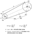
次に、この実施の形態にかかるビデオゲームにおいて、障害物を回避するように仮想カメラの視点の位置を制御するために設定されるカメラコリジョンについて説明する。図2は、この実施の形態にかかるビデオゲームで設定されるカメラコリジョンの例を示す図である。図示するように、カメラコリジョン300は、仮想カメラの視点201を中心とした半径Rの球に設定されるカメラ周辺領域301と、被写体(プレイヤキャラクタ)202を中心とした半径rの球に設定される被写体周辺領域302と、カメラ周辺領域301と被写体周辺領域302の間の円錐台形状の領域に設定されるカメラ被写体間領域303とからなる。
Next, camera collision set in order to control the position of the viewpoint of the virtual camera so as to avoid an obstacle in the video game according to this embodiment will be described. FIG. 2 is a diagram showing an example of camera collision set in the video game according to this embodiment. As shown in the drawing, the
カメラ周辺領域301の半径Rと、被写体周辺領域302の半径rとは、仮想カメラの視点201の位置と被写体202の位置との間の距離Dに応じて変化させられる。すなわち、仮想カメラの視点201と被写体202の位置との間の距離Dが所定の基準値である距離(基準距離)Dsとなっているときにおける半径R、rの標準値をそれぞれRs、rsとした場合、カメラ周辺領域301の半径R、被写体周辺領域302の半径rは、それぞれ数式1に示すように求められる。
The radius R of the camera
(数1)
R=Rs×(D/Ds)α
r=rs×(D/Ds)β
ここで、α、βは、所定の定数であって、α=βとしてもよい。
(Equation 1)
R = R s × (D / D s ) α
r = r s × (D / D s ) β
Here, α and β are predetermined constants, and α may be set to β.
この数式1から分かるように、カメラコリジョン300の大きさを定めるカメラ周辺領域301の半径R、被写体周辺領域302の半径rは、仮想カメラの視点201の位置と被写体202の位置との間の距離Dが基準距離Dsよりも小さくなると標準値Rs、rsよりも小さくなる。仮想カメラの視点201の位置は、通常は被写体202の位置との間の距離Dが基準距離Dsとなる位置に設定されるが、カメラコリジョン300に障害物が存在すると、より被写体202の位置に近い位置に設定される。
As can be seen from
仮想カメラの視点201の位置は、カメラコリジョン300に障害物が存在していなければ、被写体202となるプレイヤキャラクタの移動またはLRボタンの入力に応じて、被写体202との間の距離を基準距離Dsに保ちながら移動させられる。すなわち、カメラコリジョン300に障害物が存在していなければ、プレイヤキャラクタ(被写体202)が移動すると、プレイヤキャラクタと平行に同距離だけ、視軸203の方向を変化させずに仮想カメラの視点201の位置が移動する。また、LRボタンからの指示が入力されると、被写体202となるプレイヤキャラクタとの距離を距離Dsに保ちながら、被写体202を中心に所定角度だけ回転移動し、これに伴って、仮想カメラの視軸203の方向が変化させられる。
If there is no obstacle in the
仮想カメラの視点201の位置と被写体202の位置との間の距離Dが基準距離Dsとなっている状態から被写体202の移動またはLRボタンからの入力に応じて次に仮想カメラの視点201が移動される位置(次候補位置)において、カメラコリジョン300の範囲内に障害物が存在することとなる場合には、仮想カメラの視点201の位置は、次候補位置よりもさらに被写体202に向けて所定距離だけ移動させられる(視軸203の方向に変化なし)。
Then the virtual
仮想カメラの視点201の位置が被写体202に向けて移動される、すなわち距離Dが小さくなると、カメラ周辺領域301の半径Rと被写体周辺領域302の半径rが小さくなり、カメラコリジョン300の大きさが縮小されるが、縮小されたカメラコリジョン300に障害物が存在しなければ、仮想カメラの視点201の位置が決められる。縮小されたカメラコリジョン300でも障害物が存在するようであれば、カメラコリジョン300内に障害物が存在しなくなる位置まで、仮想カメラの視点201の位置は被写体202の方向に近づけられる(視軸203の方向に変化なし)。
When the position of the
また、仮想カメラの視点201の位置と被写体202の位置との間の距離Dが基準距離Dsよりも短くなっている状態から被写体202の移動またはLRボタンからの入力に応じて次に仮想カメラの視点201が移動される位置(次候補位置)において、カメラコリジョン300の範囲内に障害物が存在しないこととなる場合には、仮想カメラの視点201の位置は、仮想カメラの視点201の位置と被写体202の位置との間の距離Dが基準距離Dsより小さいことを条件として、次候補位置よりも被写体202から所定距離だけ遠くに移動される(視軸203の方向に変化なし)。
Also, then the virtual camera according the state where the distance D between the position of the subject 202 of the
仮想カメラの視点201の位置が被写体202から遠くに移動される、すなわち距離Dが大きくなると、カメラ周辺領域301の半径Rと被写体周辺領域302の半径rが大きくなり、カメラコリジョン300の大きさが拡大されるが、拡大されたカメラコリジョン300に障害物が存在すれば、仮想カメラの視点201の位置が再び被写体202に向けて所定距離だけ移動させられ、元の次候補位置まで戻される(視軸203の方向に変化なし)。
When the position of the
また、仮想カメラの視点201の位置が被写体202から遠くに移動され、これによって大きさが拡大されたカメラコリジョン300においても障害物が存在しなければ、距離Dが基準距離Dsとなるまでか、カメラコリジョン300に障害物の存在する状態での最大距離となるまで、想カメラ201の位置がさらに被写体202から遠くに所定距離だけ移動させられる(視軸203の方向に変化なし)。
The position of the
このように仮想カメラの視点201の位置と被写体202の間の距離Dに応じて大きさの変化するカメラコリジョン300に障害物が存在しなくなるように仮想カメラの視点201の移動を制御することによって、仮想カメラの視点201の位置が障害物の存在によって急激に変化させられることがなく、滑らかに移動されることとなる。なお、カメラコリジョン300の設定と仮想カメラの視点201の位置の移動の関係については、詳しく後述する。
In this way, by controlling the movement of the
なお、カメラコリジョン300に障害物が存在するかどうかは、カメラ周辺領域301、被写体周辺領域302、及びカメラ被写体間領域303のそれぞれについて判断され、カメラ周辺領域301、被写体周辺領域302、及びカメラ被写体間領域303の何れかに障害物が存在すると判断されれば、カメラコリジョン300に障害物が存在すると判断されることとなる。
Whether there is an obstacle in the
ここで、カメラ周辺領域301に障害物が存在するかどうかは、仮想カメラの視点201の位置と障害物となり得る各オブジェクトの間の距離が半径R以下であるかどうかによって判断すればよい。同様に、被写体周辺領域302に障害物が存在するかどうかは、被写体202の位置と障害物となり得る各オブジェクトの間の距離が半径r以下であるかどうかによって判断すればよい。
Here, whether or not there is an obstacle in the camera
カメラ被写体間領域303については、例えば、仮想カメラの視点201の位置、被写体202の位置、並びにカメラ周辺領域301及び被写体周辺領域302の半径R、rによって定義される円錐(カメラ被写体間領域303を構成する円錐台の一部となる)に障害物が存在するかどうかを該円錐の頂点からの角度の計算によって判断し、さらに当該障害物の存在するのが該円錐の頂点からの距離の計算によってカメラ被写体領域303を構成する円錐台に含まれない部分であるかを判断すればよい。
As for the inter-camera
上記のようにして仮想カメラの視点201の位置及び視軸203の方向が定められると、透視変換の処理によって、視点201及び視軸203を基準として所定の角度の範囲に設定される視界並びに前方クリップ面及び後方クリップ面により形成されるクリッピング範囲に含まれる各オブジェクトを仮想スクリーン上に投影した画像が生成される。
When the position of the
より具体的に説明すると、制御部103は、仮想カメラの視点201の位置及び視軸203の方向に応じたクリッピング範囲に含まれる各オブジェクトを構成する各ポリゴンの各頂点のワールド座標系(仮想3次元空間の座標系)を、透視変換の処理によって視点座標系の座標に変換し、さらにスクリーン座標系(仮想スクリーン上における座標系)の座標に変換する。そして、スクリーン座標系に変換した各ポリゴンの情報とともにグラフィック処理部111に描画命令を出力する。
More specifically, the control unit 103 determines the world coordinate system (virtual 3) of each vertex of each polygon constituting each object included in the clipping range according to the position of the
描画命令を受け取ったグラフィック処理部111は、制御部103から渡された各ポリゴンの情報に従って、隠面消去の処理を行いながらクリッピング範囲に含まれる各オブジェクトを仮想スクリーンに投影した画像の画像データをフレームメモリ112(当該フレーム期間において書き込み用)に書き込んでいく。グラフィック処理部111は、また、前のフレーム期間でフレームメモリ112に書き込まれた画像データを読み出し、ビデオ信号として表示装置121に出力するものとなる。 The graphic processing unit 111 that has received the drawing command performs image data of an image obtained by projecting each object included in the clipping range on the virtual screen while performing hidden surface removal processing according to the information of each polygon passed from the control unit 103. Data is written into the frame memory 112 (for writing during the frame period). The graphic processing unit 111 also reads out the image data written in the frame memory 112 in the previous frame period, and outputs the image data to the display device 121 as a video signal.
以下、この実施の形態にかかるビデオゲームにおける処理について説明する。この実施の形態にかかるビデオゲームは、プレイヤが入力部161の操作によりプレイヤキャラクタをゲーム空間となる仮想3次元空間内で移動させることでゲームが進行される。仮想カメラの視点201の位置は、被写体202となるプレイヤキャラクタの移動に追随して移動する。また、プレイヤは、ゲームを進行させているときにおいて、入力部161のLRボタンの操作により仮想カメラの視点201の位置を移動させることができる。なお、ゲーム空間には様々なイベントが設定されており、プレイヤキャラクタの移動した位置に応じてイベントが発生するが、イベントの発生については本発明とは関係がないため、詳細な説明を省略する。
Hereinafter, processing in the video game according to this embodiment will be described. In the video game according to this embodiment, the game is progressed by the player moving the player character in a virtual three-dimensional space as a game space by operating the input unit 161. The position of the
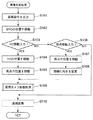
この実施の形態にかかるビデオゲームにおいてゲームが進行していく様子は、1フレーム期間毎にゲームの進行状況に応じて生成されるゲーム画面としてプレイヤに示される。図3は、この実施の形態にかかるビデオゲームにおいて、ゲーム画面として表示装置121の表示画面122に表示される画像の画像データを生成するために、制御部103が1フレーム期間毎に行う画像生成処理を示すフローチャートである。 In the video game according to this embodiment, how the game progresses is shown to the player as a game screen generated according to the progress of the game every frame period. FIG. 3 shows image generation performed by the control unit 103 for each frame period in order to generate image data of an image displayed on the display screen 122 of the display device 121 as a game screen in the video game according to this embodiment. It is a flowchart which shows a process.
1フレームの期間が開始されると、制御部103は、前のフレーム期間における透視変換の処理(ステップS110:後述)でスクリーン座標系の座標に変換されたクリッピング範囲内に含まれる各オブジェクトを構成する各ポリゴンの頂点に関する座標をグラフィック処理部111に渡すとともに、グラフィック処理部111に描画命令を出力する(ステップS101)。 When the period of one frame is started, the control unit 103 configures each object included in the clipping range converted into the coordinates of the screen coordinate system in the perspective conversion process (step S110: described later) in the previous frame period. The coordinates relating to the vertices of each polygon to be performed are transferred to the graphic processing unit 111 and a drawing command is output to the graphic processing unit 111 (step S101).
グラフィック処理部111は、描画命令が出力されると、制御部103から受け取った各ポリゴンの情報に従ってフレームメモリ112(今回のフレーム期間において書き込み用)に画像データを書き込む。また、グラフィック処理部111は、前のフレーム期間でフレームメモリ112(今回のフレーム期間において読み出し用)からの画像データの読み出しを開始し、1フレーム分のビデオ信号の出力を開始させる。 When the drawing command is output, the graphic processing unit 111 writes the image data in the frame memory 112 (for writing in the current frame period) according to the information on each polygon received from the control unit 103. In addition, the graphic processing unit 111 starts reading image data from the frame memory 112 (for reading in the current frame period) in the previous frame period, and starts outputting video signals for one frame.
次に、制御部103は、ゲームの進行状況に応じて仮想3次元空間に存在する各ノンプレイヤキャラクタの位置を移動させる(ステップS102)。ここでは、全てのノンプレイヤキャラクタの位置を移動させなければならない訳ではなく、ゲームの進行状況によっては、位置の移動されるノンプレイヤキャラクタが1つもなくてもよい。なお、ノンプレイヤキャラクタの位置の移動については、従来よりこの種のビデオゲームにおいて行われていたのと同じ処理を適用すればよい。 Next, the control unit 103 moves the position of each non-player character existing in the virtual three-dimensional space according to the progress of the game (step S102). Here, the positions of all the non-player characters do not have to be moved, and depending on the progress of the game, there may be no non-player character whose position is moved. For the movement of the position of the non-player character, the same processing as that conventionally performed in this type of video game may be applied.
次に、制御部103は、入力部161の方向キーからの指示が入力されているかどうかにより、被写体202となるプレイヤキャラクタを仮想3次元空間で移動させるための指示が入力されているかどうかを判定する(ステップS103)。プレイヤキャラクタを移動させるための指示が入力されている場合には、制御部103は、仮想カメラの視軸203の向き及び該入力された指示に応じてプレイヤキャラクタの仮想3次元空間における位置を移動させ(ステップS104)、また、プレイヤキャラクタの移動に追随して仮想カメラの視点201の位置を移動させる(ステップS105)。そして、ステップS109の処理に進む。
Next, the control unit 103 determines whether or not an instruction for moving the player character serving as the subject 202 in the virtual three-dimensional space is input depending on whether or not an instruction from the direction key of the input unit 161 is input. (Step S103). When an instruction for moving the player character is input, the control unit 103 moves the position of the player character in the virtual three-dimensional space according to the direction of the
プレイヤキャラクタを移動させるための指示が入力されていない場合には、制御部103は、入力部161のLRキーからの指示が入力されているかどうかにより、仮想カメラの視点201の位置を移動させるための指示が入力されているかどうかを判定する(ステップS106)。仮想カメラの視点201の位置を移動させるための指示が入力されていなければ、仮想カメラの視点201の位置及び被写体202の位置は前回のフレーム期間と同じままであり、この位置でカメラコリジョン300内に障害物が存在することはないので、そのままステップS110の処理に進む。
When an instruction for moving the player character is not input, the control unit 103 moves the position of the
仮想カメラの視点201の位置を移動させるための指示が入力されていれば、制御部103は、該入力された指示に応じて仮想カメラの視点201の位置を移動させ(ステップS107)、また、移動した視点201の位置においてプレイヤキャラクタ(被写体202)を向くように仮想カメラの視軸203の向きを変更する(ステップS108)。そして、ステップS109の処理に進む。
If an instruction for moving the position of the
ステップS109では、制御部103は、詳細を後述する仮想カメラ制御処理を行って、仮想カメラの視点201の位置をカメラコリジョン300内に障害物となるオブジェクトが存在しない位置に制御する。仮想カメラ制御処理によって仮想カメラの視点201の位置が最終的に設定されると、ステップS110の処理に進む。
In step S <b> 109, the control unit 103 performs virtual camera control processing, which will be described in detail later, to control the position of the
ステップS110では、制御部103は、ステップS109までに定められた今回のフレーム期間における仮想カメラの視点201の位置及び視軸203の方向に応じて定められるクリッピング範囲に存在する各オブジェクトを構成する各ポリゴンの頂点の座標を、ワールド座標系の座標からスクリーン座標系の座標に変換する透視変換の処理を行う。そして、透視変換の処理が終了すると、今回のフレーム期間における画像生成処理が終了する。また、次のフレーム期間が開始すると、新たに画像生成処理が開始されるものとなる。
In step S110, the control unit 103 configures each object included in the clipping range determined according to the position of the
図4は、ステップS109の仮想カメラ制御処理を詳細に示すフローチャートである。仮想カメラ制御処理においては、制御部103は、現時点における仮想カメラの視点201の位置及び被写体202(プレイヤキャラクタ)の位置との間の距離Dを算出する(ステップS201)。制御部103は、算出した距離Dに従って前述した数式1の演算を行い、カメラ周辺領域301の半径Rと被写体周辺領域302の半径rとを算出する(ステップS202)。
FIG. 4 is a flowchart showing in detail the virtual camera control process in step S109. In the virtual camera control process, the control unit 103 calculates a distance D between the current position of the
次に、制御部103は、現時点における仮想カメラの視点201及び被写体202の位置、並びに算出した半径R、rに応じて定められるカメラコリジョン300の範囲内に、プレイヤキャラクタ及びノンプレイヤキャラクタ以外の障害物となるオブジェクトが存在するかどうかを判定する(ステップS203)。ステップS203においてカメラコリジョン300の範囲内に障害物となるオブジェクトが存在する場合には、制御部103は、仮想カメラの視点201の位置を被写体202の位置に向けて所定距離だけ近づける(ステップS204)。そして、ステップS201の処理に戻る。
Next, the control unit 103 determines the obstacles other than the player character and the non-player character within the range of the
ステップS203においてカメラコリジョンの範囲内に障害物となるオブジェクトが存在しない場合には、制御部103は、ステップS201で直近に算出した距離Dが基準距離Dsとなっているかどうかを判定する(ステップS205)。距離Dが基準距離Dsとなっている場合には、現時点で求められている視点201の位置が今回のフレーム期間における仮想カメラの視点201の位置となるので、そのまま仮想カメラ制御処理を終了して、図3のフローチャートに復帰する。
When the object that becomes an obstacle within the range of the camera collision does not exist in step S203, the control unit 103 determines whether the distance D calculated most recently in step S201 is the reference distance D s (Step S205). When the distance D is the reference distance D s , the position of the
算出した距離Dが基準距離Dsとなっていない場合には、制御部103は、仮想カメラの視点201の位置を被写体202の位置から所定距離だけ遠ざける(ステップS206)。制御部103は、ここでまた現時点における仮想カメラの視点201の位置及び被写体202(プレイヤキャラクタ)の位置との間の距離Dを算出する(ステップS207)。制御部103は、算出した距離Dに従って前述した数式1の演算を行い、カメラ周辺領域301の半径Rと被写体周辺領域302の半径rとを算出する(ステップS208)。
If the calculated distance D is not the reference distance D s, the control unit 103, away by a predetermined distance position of the
次に、制御部103は、現時点における仮想カメラの視点201及び被写体202の位置、並びに算出した半径R、rに応じて定められるカメラコリジョン300の範囲内に、プレイヤキャラクタ及びノンプレイヤキャラクタ以外の障害物となるオブジェクトが存在するかどうかを判定する(ステップS209)。
Next, the control unit 103 determines the obstacles other than the player character and the non-player character within the range of the
ステップS209においてカメラコリジョン300の範囲内に障害物となるオブジェクトが存在する場合には、制御部103は、仮想カメラの視点201の位置を被写体202の位置に向けて所定距離だけ近づける(ステップS210)。これにより、現時点で求められている視点201の位置がカメラコリジョン300の範囲内に障害物の存在しない条件で距離Dが基準距離Dsに最も近くなる位置となるので、これで仮想カメラ制御処理を終了して、図3のフローチャートに復帰する。
If there is an object that becomes an obstacle in the range of the
ステップS209においてカメラコリジョン300の範囲内に障害物となるオブジェクトが存在しない場合には、制御部103は、ステップS201で直近に算出した距離Dが基準距離Dsとなっているかどうかを判定する(ステップS211)。距離Dが基準距離Dsとなっている場合には、現時点で求められている視点201の位置が今回のフレーム期間における仮想カメラの視点201の位置となるので、そのまま仮想カメラ制御処理を終了して、図3のフローチャートに復帰する。
When the object that becomes an obstacle within the range of the
ステップS211で距離Dが基準距離Dsとなっていない場合には、少なくとも現時点における仮想カメラの視点201の位置ではカメラコリジョン300の範囲内に障害物となるオブジェクトは存在しないが、距離Dがより基準距離Dsに近くなる位置まで仮想カメラの視点201の位置を移動してもカメラコリジョン300の範囲内に障害物となるオブジェクトが存在していない可能性もある。従って、この場合、制御部103は、ステップS206の処理に戻って、さらに処理を続けるものとなる。
If the distance D is not the reference distance D s in step S211, there is no obstacle object within the range of the
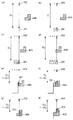
以下、この実施の形態にかかるビデオゲームにおいて、障害物の存在する領域における被写体202の移動に応じた仮想カメラの視点201の移動について具体的に説明する。図5(a)〜(h)、図6(a)〜(g)は、この実施の形態にかかるビデオゲームにおけるカメラコリジョン300の設定と、透視変換の際に障害物を避けるようにするための仮想カメラの視点201の位置の移動の具体例を模式的に示す図である。
Hereinafter, in the video game according to this embodiment, the movement of the
まず、図5(a)に示すように、仮想カメラの視点201の位置と被写体(プレイヤキャラクタ)202の位置との間の距離がD1(=Ds)にあり、ここで設定されるカメラ周辺領域301、被写体周辺領域302及びカメラ被写体間領域303で構成されるカメラコリジョン300の範囲内には、障害物400が存在していないものとする。次に、図5(b)に示すように、被写体202の位置が移動し、これに追随して仮想カメラの視点201の位置を移動すると、障害物400がカメラコリジョン300の範囲内に入ってしまうことになるものとする。
First, as shown in FIG. 5A, the distance between the position of the
この場合には、図5(c)に示すように、仮想カメラの視点201の位置が被写体202の位置に近づけられる。こうして仮想カメラの視点201の位置及び被写体(プレイヤキャラクタ)202の位置との間の距離がD2(<D1)となると、カメラコリジョン300の大きさが小さくなり、この大きさでのカメラコリジョン300の範囲内には障害物400が入らなくなるものとなる。もっとも、図5(d)に示すように、被写体202の位置がさらに移動し、これに追随して仮想カメラの視点201の位置を移動すると、障害物400がカメラコリジョン300の範囲内に入ってしまうことになるものとする。
In this case, as shown in FIG. 5C, the position of the
この場合には、図5(e)に示すように、仮想カメラの視点201の位置が被写体202の位置にさらに近づけられる。こうして仮想カメラの視点201の位置及び被写体202の位置との間の距離がD3(<D2)となると、カメラコリジョン300の大きさがさらに小さくなり、この大きさでのカメラコリジョン300の範囲内には障害物400が入らなくなるものとなる。もっとも、図5(f)に示すように、被写体202の位置がさらに移動し、これに追随して仮想カメラの視点201の位置を移動すると、障害物400がカメラコリジョン300の範囲内に入ってしまうことになるものとする。
In this case, as shown in FIG. 5E, the position of the
この場合には、図5(g)に示すように、仮想カメラの視点201の位置が被写体202の位置にさらに近づけられる。こうして仮想カメラの視点201の位置及び被写体202の位置との間の距離がD4(<D3)となると、カメラコリジョン300の大きさがさらに小さくなり、この大きさでのカメラコリジョン300の範囲内には障害物400が入らなくなるものとなる。もっとも、図5(h)に示すように、被写体202の位置がさらに移動し、これに追随して仮想カメラの視点201の位置を移動すると、障害物400がカメラコリジョン300の範囲内に入ってしまうことになるものとする。
In this case, as shown in FIG. 5G, the position of the
この場合には、図6(a)に示すように、仮想カメラの視点201の位置が被写体202の位置にさらに近づけられる。こうして仮想カメラの視点201の位置及び被写体202の位置との間の距離がD5(<D4)となると、カメラコリジョン300の大きさがさらに小さくなり、この大きさでのカメラコリジョン300の範囲内には障害物400が入らなくなるものとなる。もっとも、図6(b)に示すように、被写体202の位置がさらに移動し、これに追随して仮想カメラの視点201の位置を移動すると、障害物400がカメラコリジョン300の範囲内に入ってしまうことになるものとする。
In this case, as shown in FIG. 6A, the position of the
この場合には、図6(c)に示すように、仮想カメラの視点201の位置が被写体202の位置にさらに近づけられる。こうして仮想カメラの視点201の位置及び被写体202の位置との間の距離がD6(<D5)となると、カメラコリジョン300の大きさがさらに小さくなり、この大きさでのカメラコリジョン300の範囲内には障害物400が入らなくなるものとなる。もっとも、図6(d)に示すように、被写体202の位置がさらに移動し、これに追随して仮想カメラの視点201の位置を移動すると、障害物400がカメラコリジョン300の範囲内に入ってしまうことになるものとする。
In this case, as shown in FIG. 6C, the position of the
この場合には、図6(e)に示すように、仮想カメラの視点201の位置が被写体202の位置にさらに近づけられる。こうして仮想カメラの視点201の位置及び被写体202の位置との間の距離がD7(<D6)となると、カメラコリジョン300の大きさがさらに小さくなり、この大きさでのカメラコリジョン300の範囲内には障害物400が入らなくなるものとなる。もっとも、図6(f)に示すように、被写体202の位置がさらに移動し、これに追随して仮想カメラの視点201の位置を移動すると、障害物400がカメラコリジョン300の範囲内に入ってしまうことになるものとする。
In this case, as shown in FIG. 6E, the position of the
この場合には、図6(g)に示すように、仮想カメラの視点201の位置が被写体202の位置にさらに近づけられる。こうして仮想カメラの視点201の位置及び被写体202の位置との間の距離がD8(<D7)となると、カメラコリジョン300の大きさがさらに小さくなり、この大きさでのカメラコリジョン300の範囲内には障害物400が入らなくなるものとなる。
In this case, as shown in FIG. 6G, the position of the
このように、この実施の形態にかかるビデオゲームでは、図5(a)、図5(c)、図5(e)、図5(g)、図6(a)、図6(c)、図6(e)、図6(g)に示す位置で仮想カメラの視点201の位置が移動していく場合、これらの図に矢印で示すように、仮想カメラの視点201の移動は、滑らかに行われていることが分かる。特に、図6(a)、図6(c)、図6(e)、図6(g)に示すように、仮想カメラの視点201の位置よりも後側(被写体202よりも遠い側)に障害物がある場合も、カメラ周辺領域301が仮想カメラの視点201の位置より後側の領域までを含んでいるために、仮想カメラの視点201の移動が、滑らかに行われていることが分かる。
Thus, in the video game according to this embodiment, FIG. 5A, FIG. 5C, FIG. 5E, FIG. 5G, FIG. 6A, FIG. When the position of the
なお、図5、図6においては、被写体202となるプレイヤキャラクタの移動に追随して仮想カメラの視点201の位置が移動し、これにより仮想カメラの視点201の位置と被写体202の位置とを結ぶ直線に障害物400が徐々に近づいてくる場合を説明したが、入力部161のLRボタンから入力された指示により仮想カメラの視点201の位置が移動し、これにより仮想カメラの視点201の位置と被写体202の位置とを結ぶ直線に障害物400が徐々に近づいてくる場合にも、仮想カメラの視点201の位置が滑らかに移動されるものとなる。
5 and 6, the position of the
また、被写体202となるプレイヤキャラクタの移動または入力部161のLRボタンからの指示の入力に従って仮想カメラの視点201の位置と被写体202の位置とを結ぶ直線から障害物400が徐々に遠ざかっていく場合には、図5(a)、図5(c)、図5(e)、図5(g)、図6(a)、図6(c)、図6(e)、図6(g)の順番とは逆の関係で仮想カメラの視点201の位置が移動していくことになるので、仮想カメラの視点201の位置が滑らかに移動されるものとなる。
Further, when the
比較例として、従来例にかかるビデオゲームにおいて、障害物の存在する領域における被写体202の移動に応じた仮想カメラの視点の移動について具体的に説明する。図7(a)〜(d)は、従来例にかかるビデオゲームにおいて、透視変換の際に障害物を避けるようにするための仮想カメラの視点201の位置の移動の具体例を模式的に示す図である。
As a comparative example, in the video game according to the conventional example, the movement of the viewpoint of the virtual camera according to the movement of the subject 202 in the area where the obstacle exists will be specifically described. FIGS. 7A to 7D schematically show specific examples of movement of the position of the
まず、図7(a)に示すように、仮想カメラの視点201の位置及び被写体(プレイヤキャラクタ)202の位置との間の距離がD1(=Ds)にあるものとする。ここでの仮想カメラの視点201の位置及び被写体202の位置関係は、図5(a)に示したものと同じであるとする。ここでは、仮想カメラの視点201の位置と被写体202の位置との間に障害物400は存在しない。
First, as shown in FIG. 7A, it is assumed that the distance between the position of the
次に、図7(b)に示すように、図5(a)の状態から図5(b)に示す状態に移動する場合と同じだけ被写体202の位置が移動し、これに追随して仮想カメラの視点201の位置が移動したものとする。図5(b)ではカメラコリジョン300の範囲内に障害物400が存在することとなったが、図7(b)では仮想カメラの視点201の位置と被写体202との間に障害物400が存在しないので、仮想カメラの視点201の位置が被写体202の位置に近づけられることはなく、仮想カメラの視点201の位置をこの位置において透視変換の処理が行われる。
Next, as shown in FIG. 7 (b), the position of the subject 202 moves as much as when moving from the state of FIG. 5 (a) to the state shown in FIG. 5 (b). Assume that the position of the
さらに、図7(c)に示すように、図5(c)の状態から図5(d)に示す状態に移動する場合と同じだけ被写体202の位置が移動し、これに追随して仮想カメラの視点201の位置が移動したものとする。図5(d)でもカメラコリジョン300の範囲内に障害物400が存在することとなったが、図7(c)でも仮想カメラの視点201の位置と被写体202との間に障害物400が存在しないので、仮想カメラの視点201の位置が被写体202の位置に近づけられることはなく、仮想カメラの視点201の位置をこの位置において透視変換の処理が行われる。
Further, as shown in FIG. 7 (c), the position of the subject 202 moves as much as the case of moving from the state of FIG. 5 (c) to the state shown in FIG. 5 (d). Assume that the position of the
その後、図7(d)に示すように、図5(e)の状態から図5(f)に示す状態に移動する場合と同じだけ被写体202の位置が移動し、これに追随して仮想カメラの視点201の位置が移動したものとする。図7(d)の状態では、仮想カメラの視点201の位置と被写体202との間に障害物400が存在してしまうこととなる。
Thereafter, as shown in FIG. 7D, the position of the subject 202 moves as much as when moving from the state of FIG. 5E to the state shown in FIG. Assume that the position of the
そこで、図7(e)に示すように、仮想カメラの視点201の位置と被写体202との間に障害物400が存在しなくなる位置、すなわち仮想カメラの視点201の位置と被写体202との間の距離DがD0(≪D1)となる位置まで、仮想カメラの視点201の位置が移動されることとなる。その後は、図7(f)に示すように、被写体202の位置の移動に追随して、被写体202の位置との間の距離を一定に保ちつつ仮想カメラの視点201の位置が移動される。
Therefore, as illustrated in FIG. 7E, a position where the
その後も、図7(g)に示すように、被写体202の位置が移動し、これに追随して、仮想カメラの視点201の位置と被写体202との間に障害物400が存在してしまうこととなるまで、仮想カメラの視点201の位置が移動したものとする。そこで、図7(h)に示すように、仮想カメラの視点201の位置と被写体202との間に障害物400が存在しなくなる位置、すなわち仮想カメラの視点201の位置と被写体202との間の距離DがD00(≪D0)となる位置まで、仮想カメラの視点201の位置が移動されることとなる。
After that, as shown in FIG. 7G, the position of the subject 202 moves, and the
このように、比較例にかかる従来のビデオゲームでは、図7(a)、(b)、(c)、(e)、(f)、(h)に示す位置で仮想カメラの視点201の位置が移動していく場合、図7(e)、(f)、(h)に矢印で示すように、仮想カメラの視点201の移動が急激に行われてしまうことが分かる。
As described above, in the conventional video game according to the comparative example, the position of the
以上説明したように、この実施の形態にかかるビデオゲームでは、プレイヤキャラクタを被写体202として透視変換の処理が行われ、表示装置121の表示画面122として表示されるゲームの画像が1フレーム期間毎に生成される。ここで、プレイヤが入力部161の方向キーから指示を入力すると、入力された指示に応じた方向に被写体202となるプレイヤキャラクタが移動し、これに追随して仮想カメラの視点201の位置も移動する。また、プレイヤが入力部161のLRボタンから指示を入力すると、仮想カメラの視軸203の方向を被写体202となるプレイヤキャラクタを向くように変化させつつ、仮想カメラの視点201の位置が周回移動、または極座標上で移動させられる。
As described above, in the video game according to this embodiment, the perspective transformation process is performed with the player character as the subject 202, and the game image displayed on the display screen 122 of the display device 121 is displayed every frame period. Generated. Here, when the player inputs an instruction from the direction key of the input unit 161, the player character that becomes the subject 202 moves in the direction corresponding to the input instruction, and the position of the
このように仮想カメラの視点201の位置は、被写体202となるプレイヤキャラクタの移動に追随して移動されるか、入力部161のLRボタンからの入力によって移動されるものであるが、カメラコリジョン300の範囲内に障害物が存在することになると、該カメラコリジョン300の範囲内に障害物が入らない位置となるまで、仮想カメラの視点201の位置が被写体202の位置の方向に向けて移動される。
As described above, the position of the
ここで、カメラコリジョン300は、仮想カメラの視点201の位置を中心とする半径Rの球に設定されるカメラ周辺領域301と、被写体202の位置を中心とする半径rの球に設定される被写体周辺領域302と、その間の円錐台形状のカメラ被写体間領域303とから構成されている。カメラ周辺領域301の半径Rと被写体周辺領域302の半径rは、仮想カメラの視点201の位置と被写体202の位置との間の距離Dが基準距離Dsよりも小さくなると、基準距離Dsのときの標準値である半径Rs、rsよりも小さくなり、カメラコリジョン300の大きさが縮小されるものとなっている。
Here, the
このため、仮想カメラの視点201の位置から比較的離れた位置でカメラコリジョン300の範囲内に障害物が存在している場合には、仮想カメラの視点201の位置を被写体202の位置に近づければカメラコリジョン300の大きさが縮小されるので、被写体202の位置に近づけた位置をカメラコリジョン300の範囲内に障害物の存在しない位置として仮想カメラの視点201の位置を定めることができる。
For this reason, when an obstacle exists within the range of the
このため、例えば、仮想カメラ201の視点の位置と被写体202の位置とを結ぶ直線と障害物の間の距離が徐々に短くなっていくような場合に、仮想カメラの視点201の位置を被写体202の位置に向けて徐々に近づけていくことが可能になる。そして、この直線上に障害物が入り込むときには、その直前までに仮想カメラの視点201の位置はかなり被写体202の位置の方に移動しているので、障害物の位置よりも被写体202の位置からの距離が短い位置まで仮想カメラの視点201の位置を移動させるにしても、仮想カメラの視点201の位置が急激に移動されてしまうことがない。
Therefore, for example, when the distance between the straight line connecting the position of the viewpoint of the
また、仮想カメラの視点201の位置と被写体202の位置とを結ぶ直線と障害物との間の距離が徐々に長くなっていくような場合には、仮想カメラの視点201の位置を被写体202から一気に遠ざけすぎるとカメラコリジョン300が大きくなってカメラコリジョン300に障害物が入り込んでしまうこととなるので、仮想カメラの視点201の位置は、被写体202の位置から徐々に遠ざかっていくものとなる。
Further, when the distance between the straight line connecting the position of the
このように、この実施の形態にかかるビデオゲームでは、仮想カメラ201の視点の位置と被写体202の位置との間に障害物が入り込んでしまうのを回避するように仮想カメラの視点201の位置を制御するものとしても、仮想カメラの視点201の位置の移動が滑らかに行われるものとなっている。これにより、表示装置121の表示画面122に表示された画像を見ているプレイヤが、表示される画像の変化に違和感を生じさせてしまうことがない。また、仮想カメラの視点201の位置が急激に切り替わることがないため、表示されている画像を見ていることでプレイヤがカメラ酔いをしてしまうこともない。
As described above, in the video game according to this embodiment, the position of the
さらに、カメラコリジョン300の範囲内に存在する障害物に対して透過処理を行う訳でもないので、表示装置121の表示画面122に表示された画像において本来障害物に隠されて見える筈のないオブジェクトがプレイヤに見えてしまったりするということもない。これにより、表示装置121の表示画面122に表示された画像を見ているプレイヤが、表示される画像において視認しているオブジェクトに違和感を生じさせてしまうこともない。
Further, since the transparent processing is not performed on the obstacle existing in the range of the
また、カメラ周辺領域301と被写体周辺領域302は、それぞれ仮想カメラの視点201の位置、被写体202の位置を中心とする球に含まれる領域に設定されている。このため、カメラコリジョン300のうちでカメラ周辺領域301や被写体周辺領域302に障害物が存在するかどうかは、仮想カメラの視点201の位置や被写体202の位置と障害物となり得る各オブジェクトを構成するポリゴンの頂点の位置との間の距離計算で容易に判断することができる。また、仮想カメラの視点201の位置と被写体202の位置との間の距離に応じてカメラ周辺領域301や被写体周辺領域302の大きさを変化させるものとしても、計算が複雑になることはない。
The camera
また、カメラコリジョン300を構成するカメラ周辺領域301は、仮想カメラの視点201の位置を中心とする球からなり、被写体202の位置からの距離が視点201の位置よりも遠い領域まで含んでいるため、仮想カメラの視点201の位置が障害物の位置よりも被写体202の近くに回り込んでいる場合でも、尚も滑らかに視点201の位置を移動させ続けることができる。
Further, the camera
さらに、カメラコリジョン300は、被写体202の位置を中心とする球の領域に設定される被写体周辺領域302までも含んでいるため、被写体の位置に非常に近い位置で仮想カメラ201の視点の位置と被写体202の位置とを結ぶ直線に障害物が徐々に近づいて来るような場合にも、仮想カメラの視点201の位置を滑らかに移動させながら仮想カメラの視点201の位置と被写体202の位置との間に障害物が入り込んでしまうのを回避することができるようになる。
Further, since the
本発明は、上記の実施の形態に限られず、種々の変形、応用が可能である。以下、本発明に適用可能な上記の実施の形態の変形態様について説明する。 The present invention is not limited to the above-described embodiment, and various modifications and applications are possible. Hereinafter, modifications of the above-described embodiment applicable to the present invention will be described.
上記の実施の形態では、仮想カメラの視点201の位置は、被写体202の位置との間の距離Dが最大でも基準距離Dsとなる位置に設定されていたが、距離Dが基準距離Dsよりも大きくなる位置に設定されることがあってもよい。この場合において、カメラ周辺領域301の半径R、被写体周辺領域302の半径rは、仮想カメラの視点201の位置と被写体202の位置との間の距離Dが基準距離Dsよりも大きくなると、距離Dが基準距離Dsである場合の標準値Rs、rsよりも大きくなるものとすることができる。
In the above embodiment, the position of the
上記の実施の形態では、仮想カメラの視軸203の向きは、常にプレイヤキャラクタに向けて制御される、すなわちプレイヤキャラクタを被写体202として制御されるものとなっていた。しかしながら、仮想カメラの視軸203を向ける被写体202となるオブジェクトは、必ずしもプレイヤキャラクタに限るものではない。被写体202となるオブジェクトは、無色透明なオブジェクト或いは領域の幅を持たないオブジェクトのように、表示画面122に表示されることのないオブジェクトであってもよい。
In the above embodiment, the orientation of the
上記の実施の形態では、仮想カメラの視点201の位置は、カメラコリジョン300の範囲内に障害物となるオブジェクトが存在しない場合には、入力部161のLRボタンからの指示の入力に従って移動させられる場合を除いては、被写体202となるプレイヤキャラクタの位置の移動に追随して移動させられるものとしていた。もっとも、入力部161の方向キーからの指示の入力によってプレイヤキャラクタの位置だけではなく向きも変化させられる場合には、この向きの変化に追随して移動させられるものとしてもよい。
In the above embodiment, the position of the
また、仮想カメラの視点201の位置は、カメラコリジョン300の範囲内に障害物となるオブジェクトが存在することによって移動される場合以外は、被写体202となるプレイヤキャラクタの位置の移動(及び向きの変化)に完全に追随して移動させられるものであってもよい。また、仮想カメラの視点201の位置は、例えば、L1ボタン及びR1ボタンからの指示の入力によって被写体202を中心に周回移動させられるが、極座標方向には移動されないものとしてもよい。
In addition, the position of the
また、仮想カメラの視点201の位置は、被写体202と仮想カメラの視点201の間の距離を調整して障害物を回避する場合以外にも、できるだけ被写体202と仮想カメラ201の間の距離を変化させずに被写体202を向くように視軸203の角度を制御することを条件として、従来より知られている任意の手法により制御するものとすることができる。例えば、仮想カメラの視点201の位置と被写体202の位置との間の距離Dが所定の範囲内にあるときには被写体202の位置が移動しても視点201の位置を固定したまま視軸203の角度の調整のみで(被写体202と仮想カメラの視点201の間の距離を変えずに)仮想カメラを被写体202に追随させるが、距離Dが所定の範囲を越える位置まで移動したときには距離Dが所定の範囲内となる位置に仮想カメラの視点201の位置を移動させるものとすることができる。
Further, the position of the
上記の実施の形態では、カメラコリジョン300の範囲内に障害物が存在するときには、仮想カメラの視点201の位置を被写体202の方向に移動させ、こうして障害物がカメラコリジョン300の範囲内に入ってしまうのを回避するものとしていた。しかしながら、障害物を回避するための仮想カメラの視点201の移動方向は、被写体202の方向に限るものではない。状況に応じて仮想カメラの視点201を被写体202の方向に移動させる場合と、それ以外の方向に移動させる場合とを併用することもできる。それ以外の方向に移動させる下記の各種手法も、任意の2つ以上のものを併用することができる。
In the above embodiment, when an obstacle exists within the range of the
例えば、カメラコリジョン300の範囲内に障害物が入らなくなるまで、仮想カメラの視点201の位置を極座標上で上方向に移動させるものとしてもよい。また、カメラコリジョン300の範囲内に障害物が入らなくなるまで、仮想カメラの視点201の位置を仮想3次元空間のZ軸方向に移動させるものとしてもよい。また、仮想カメラの視点201を高さを一定に維持させつつ移動させる場合には、カメラコリジョン300の範囲内に障害物が入ったときには、仮想カメラの視点201の位置を左回りまたは右回りで回転移動させて、カメラコリジョン300の範囲内に障害物が入らなくなるようにしてもよい。
For example, the position of the
障害物を回避するため、仮想カメラの視点201を被写体202の方向に移動させる場合も、極座標上で上下方向に移動させる場合も、左回りまたは右回りで回転移動させる場合も、さらにはこれらを組み合わせる場合も、仮想カメラの視点201の位置は、視軸203を被写体202に向けつつ仮想3次元空間において任意の位置に移動させるものとすることができる。
In order to avoid an obstacle, the
上記の実施の形態では、プレイヤキャラクタ及びノンプレイヤキャラクタ以外の仮想3次元空間における位置が変化しないオブジェクトが透視変換の際の障害物となり得るオブジェクトとされていたが、仮想3次元空間における位置の変化するオブジェクト(被写体202とならないノンプレイヤキャラクタを含んでいてもよい)も、透視変換の際の障害物となり得るオブジェクトとしてもよい。 In the above-described embodiment, an object whose position in the virtual three-dimensional space other than the player character and the non-player character does not change is an object that can become an obstacle in the perspective transformation. However, the position change in the virtual three-dimensional space The object (which may include a non-player character that does not become the subject 202) may also be an object that can be an obstacle during perspective transformation.
仮想3次元空間における位置の変化するオブジェクトも障害物となり得る場合には、仮想カメラの視点201の位置及び被写体202の位置が移動しなくても、障害物となり得るオブジェクトの位置が移動することで、カメラコリジョン300の範囲内に障害物となるオブジェクトが存在してしまうことがある。このような場合にも、ステップS109の仮想カメラ制御処理(図3)を行うものとし、カメラコリジョン300の範囲内に障害物となるオブジェクトが含まれないように仮想カメラの視点201の位置を移動させるものとすればよい。
When an object whose position changes in the virtual three-dimensional space can also be an obstacle, the position of the object that can be an obstacle moves even if the position of the
また、上記の実施の形態ではスタンドアローン型のビデオゲームを前提に説明したので、プレイヤキャラクタ以外のキャラクタは全てノンプレイヤキャラクタであるものとして説明したが、ネットワーク151を介して接続された複数のビデオゲーム装置100から各プレイヤが参加するネットワークゲームでは、各々のプレイヤに対応したプレイヤキャラクタが仮想3次元空間に存在することとなる。この場合は、他のプレイヤに対応したプレイヤキャラクタは、透視変換の際の障害物となり得るオブジェクトとすることも障害物となり得ないオブジェクトとすることもできる。ゲームにおいて一定の関係を有するプレイヤのプレイヤキャラクタだけを障害物となり得ないオブジェクトとすることもできる。 In the above embodiment, the description has been made on the assumption that the video game is a stand-alone type video game, so that all the characters other than the player character are non-player characters. However, a plurality of videos connected via the network 151 are described. In a network game in which each player participates from the game apparatus 100, a player character corresponding to each player exists in the virtual three-dimensional space. In this case, the player character corresponding to the other player can be an object that can be an obstacle during perspective transformation or an object that cannot be an obstacle. Only a player character of a player who has a certain relationship in the game can be an object that cannot be an obstacle.
上記の実施の形態では、カメラコリジョン300の範囲内に障害物となるオブジェクトが存在しないことを条件として、仮想カメラの視点201の位置と被写体202の位置との間の距離Dが基準距離Dsに最も近くなる位置まで仮想カメラの視点201の位置を被写体202の位置から遠ざけるものとしていた。もっとも、特に障害物となるオブジェクトが仮想3次元空間内を移動するものであったり、仮想3次元空間から突然消えることがあるオブジェクトであったりした場合には、距離Dが基準距離Dsとなるまで1フレーム期間で一気に仮想カメラの視点201の位置を移動させてしまうと、視点201の位置が急激になりすぎてしまうことがある。
In the above embodiment, the distance D between the position of the
そこで、カメラコリジョン300の範囲内に障害物となるオブジェクトが存在しない場合であっても、仮想カメラの視点201の位置は、前回のフレーム期間における距離Dと今回のフレーム期間における距離Dとの差が一定の範囲内となることを条件として、距離Dが基準距離Dsに近づくように移動させるものとしてもよい。例えば、図4のステップS209の処理でカメラコリジョン300の範囲内に障害物が存在しないと判定された場合に、そのまま仮想カメラ制御処理を終了させることなどにより、このような手法を実現することができる。
Therefore, even when there is no obstacle object within the range of the
上記の実施の形態では、仮想カメラの視点201の位置と被写体202の位置との間の距離Dに応じてカメラコリジョン300の大きさを変化させるものとしていたが、仮想カメラの視界は常に所定の角度になっていた。このため、仮想カメラの視点201の位置を被写体202に近づけると、透視変換により生成される画像に表示される範囲の大きさが変わってしまう。そこで、仮想カメラの視点201の位置と被写体202の位置との間の距離Dに応じて、仮想カメラの視界の大きさも変化させるものとしてもよい。
In the above-described embodiment, the size of the
これにより、表示画面122として表示される仮想3次元空間の範囲の大きさを、仮想カメラの視点201の位置と被写体202の位置との間の距離Dの変化に関わらずにほぼ同じ大きさに保つことができるので、障害物を回避するために仮想カメラの視点201の位置を被写体202の位置に近づけたり遠ざけたりしても、プレイヤが画面上であまり違和感を生じさせなくて済むようになる。
As a result, the size of the range of the virtual three-dimensional space displayed as the display screen 122 is substantially the same regardless of the change in the distance D between the position of the
上記の実施の形態では、カメラコリジョン300を構成するカメラ周辺領域301の半径Rも、被写体周辺領域302の半径rも、仮想カメラの視点201の位置と被写体202の位置との間の距離Dに応じて変化するものとなっていた。これに対して、カメラ周辺領域301の半径Rは距離Dに応じて可変とするが、被写体周辺領域302の半径rは距離Dに関わらずに一定のものとすることができる。もっとも、被写体周辺領域302の半径rも距離Dに応じて変化させる方が、仮想カメラの視点201の動きをスムーズにすることができる。
In the above embodiment, both the radius R of the camera
上記の実施の形態では、カメラコリジョン300の大きさ(カメラ周辺領域301の半径Rと被写体周辺領域302の半径r)は、仮想カメラの視点201の位置と被写体202の位置との間の距離Dに応じて決められるものとしていた。もっとも、ゲームの進行状況の違いによって、仮想カメラの視点201の位置が滑らかに流れるように動いた方が臨場感の得られる画像を生成できる場合も、仮想カメラの視点201の位置が大きく変化した方が臨場感の得られる画像を生成できる場合もある。また、障害物となり得るオブジェクトが多い場面では、カメラコリジョン300の大きさを大きくしすぎると、障害物を避けるために仮想カメラの視点201の位置の移動される量が大きくなりすぎてしまう場合がある。
In the above embodiment, the size of the camera collision 300 (the radius R of the camera
そこで、仮想カメラの視点201の位置と被写体202の位置との間に距離Dに応じてだけではなく、ゲームの場面の違いによっても、カメラコリジョン300の大きさ(カメラ周辺領域301の半径Rおよび/または被写体周辺領域302の半径r)を変化させるものとしてもよい。ゲームの場面の違いによってカメラコリジョン300の大きさを変化させる方法としては、場面毎にカメラコリジョン300の基本の大きさ(半径R、rの標準値)を予め定めておくものを適用しても、ゲームの場面を判断してカメラコリジョン300の基本の大きさ(半径R、rの標準値)を動的に変化させるものとしてもよい。
Therefore, not only according to the distance D between the position of the
ここで、カメラコリジョン300の大きさを変化させるゲームの場面の違いとしては、例えば、昼間のシーンと夜のシーンの違いを適用することができる。現実の世界では、明るいときにはカメラマンが障害物にギリギリまで近づいてから障害物を避けるように動くことができる一方、暗いときにはカメラマンが障害物に衝突してしまうのを避けるために早め早めに障害物を回避する行動を取ることが一般的だからである。この場合、ゲームの状況に応じた臨場感のある画像を生成することができるようになる。昼間のシーンと夜のシーンの違いでカメラコリジョン300の大きさを変化させるものでは、動的にカメラコリジョン300の大きさを変化させる手法が適するものとなる。
Here, as a difference in the game scene in which the size of the
また、カメラコリジョン300の大きさを変化させるゲームの場面の違いとしては、例えば、障害物となり得るオブジェクトの多いシーン/少ないシーンの違いを適用することができる。この場合、障害物となり得るオブジェクトが多い場面になっても、カメラコリジョン300に障害物が入らないようにするための仮想カメラの視点201の位置の制御が頻繁になりすぎずに済むようになる。このように障害物となり得るオブジェクトの多いシーン/少ないシーンの違いでカメラコリジョン300の大きさを変化させるものでは、障害物となり得るオブジェクトが多いか少ないかは場所毎に予め定まっていることが多いので、場所毎に定められた基本の大きさのカメラコリジョン300を用いる手法が適するものとなる。
In addition, as a difference in the game scene in which the size of the
上記の実施の形態では、カメラコリジョン300は、半径Rの球からなるカメラ周辺領域301と、半径rの球からなる被写体周辺領域302と、円錐台形状の領域からなるカメラ被写体間領域303とから構成され、カメラ周辺領域301の半径R、被写体周辺領域302の半径rともに、仮想カメラの視点201の位置と被写体202の位置との間の距離Dに応じて変化させられるものとしていた。
In the above embodiment, the
これに対して、仮想カメラの視点201の位置から見て被写体202よりも後側に障害物が存在しても問題にはならないので、被写体周辺領域302は、球形の領域とするのではなく、仮想カメラの視点201の近い部分だけの半球状の領域としてもよい。もっとも、カメラ被写体間領域303が円錐台形状の領域に設定されるのであれば、被写体周辺領域302そのものがなくてもよい。
On the other hand, since there is no problem even if an obstacle exists behind the subject 202 when viewed from the position of the
また、被写体周辺領域302がカメラコリジョン300に含まれないものとし、カメラ周辺領域300と、被写体202の位置を頂点としてカメラ周辺領域300との間に形成される円錐形状のカメラ被写体間領域とからカメラコリジョン300が構成されるものとしてもよい。この場合のカメラ被写体間領域に障害物となるオブジェクトが存在するかどうかは、被写体202の位置を中心として仮想カメラの視点201の位置と障害物となり得るオブジェクトの各頂点の位置とがなす角度と、被写体202の位置と障害物となり得るオブジェクトの拡張点の位置とがなす距離とによって求めることができる。
Further, it is assumed that the subject
また、カメラコリジョン300にカメラ周辺領域301と被写体周辺領域302とが含まれる場合には、カメラ周辺領域301の半径Rと被写体周辺領域302の半径rの何れか一方のみが、仮想カメラの視点201の位置と被写体202の位置との間の距離Dに応じて変化させられるものとしてもよい。
Further, when the
また、カメラ被写体間領域303の形状は、カメラ周辺領域301と被写体周辺領域302の形状が球形であれば理想的には円錐台形状(或いはカメラコリジョン300に被写体周辺領域302が含まれない場合には円錐形状)となるが、制御部103の処理負荷を軽減するため、角錐台形状(或いは角錐形状)にしてもよい。この角錐台(或いは角錐)の底面は、角の数が多い多角形となっているほど理想の形状に近づくが、制御部103の処理負荷が大きくなるので、制御部103の処理負荷とのバランスにより適当な画数に定めるものとすることができる。さらに、カメラ周辺領域301および/または被写体周辺領域302の形状も、多面体形状とすることができる。カメラ周辺領域301および/または被写体周辺領域302の形状は、仮想カメラの視点201の位置から被写体202の位置までの方向を長くした楕円球とすることもできる。
Further, the shape of the
また、カメラ周辺領域301は、仮想カメラの視点201の位置を中心とした領域に設定されるのではなく、仮想カメラの視点201の位置よりもやや被写体202に近い位置を中心とした領域に設定されるものとしてもよい。例えば、カメラ周辺領域301の半径Rの球で構成するものとした場合、カメラ周辺領域301の中心位置を仮想カメラの視点201の位置よりもRよりも少ない所定距離だけ被写体202に近づけた位置に設定するものとしてもよい。また、カメラ周辺領域301および/または被写体周辺領域302の形状は、高さ方向の長さを水平方向の長さよりも短くした多面体(正多面体ではない)としてもよい。この場合、カメラ被写体間領域303も、楕円角錐(台)形状となる。
The camera
さらに、仮想カメラの視点201の位置が水平方向の高さを保って移動される場合には、カメラコリジョン300が平面形状になるものとしてもよい(例えば、カメラ周辺領域301及び被写体周辺領域302を円形とし、カメラ被写体間領域303を台形とする)。ここでは、仮想カメラの視点201の位置が水平方向の高さを保って移動されるという制約があることが条件になるものの、このような制約下ではカメラコリジョン300を平面形状に設定することができ、より少ない計算量でカメラコリジョン300に障害物が存在するかどうかを判断することができるようになる。
Further, when the position of the
上記の実施の形態では、カメラコリジョン300は、仮想カメラの視点201の位置を中心として設定されるカメラ周辺領域301と、被写体202の位置を中心として設定される被写体周辺領域302と、その間のカメラ被写体間領域303とを含んでいた。つまり、仮想カメラの視点201の位置だけではなく、被写体202の位置も含むものとしていた。そして、カメラコリジョン300に障害物となるオブジェクトが存在することとなると、仮想カメラの視点201の位置を被写体202の方向に移動させるものとしていた。
In the above embodiment, the
もっとも、カメラコリジョン300の範囲内に障害物となるオブジェクトが存在するからといって、仮想カメラの視点201の位置をあまりに被写体202に近づけすぎると、被写体202がクリッピング範囲に含まれなくなってしまい、何れにしても表示画面122において被写体202が表示されなくなってしまう。また、被写体202がクリッピング範囲に含まれていたとしても、仮想カメラの視点201の位置に近すぎると、被写体202となるプレイヤキャラクタの一部のみが大アップで表示されてしまうこととなる。
However, if there is an object that becomes an obstacle in the range of the
このような不都合を回避するため、例えば、カメラコリジョン300の範囲内に障害物となるオブジェクトが存在する場合には、これを避けるために仮想カメラの視点201の位置を被写体202の位置に近づけることを基本とするが、被写体202の位置から非常に近い位置に障害物となるオブジェクトが存在するときには、これとは異なる方向、例えば、極座標の上方向に仮想カメラの視点201の位置を移動させるものとしてもよい。
In order to avoid such an inconvenience, for example, when an object that becomes an obstacle exists within the range of the
或いは、被写体202の位置から非常に近い位置に障害物となるオブジェクトが存在する場合には、カメラコリジョン300の範囲内に障害物となるオブジェクトが存在しても、仮想カメラの視点201の位置を被写体202の方向に移動させないものとしてもよい。また、カメラコリジョン300は、被写体202の近傍の位置にまで設定するものの被写体202の位置が含まれない領域に設定するものとしてもよい。
Alternatively, when an object that becomes an obstacle exists at a position very close to the position of the subject 202, the position of the
これらの場合、被写体202の位置から非常に近い位置に障害物となるオブジェクトが存在する場合には、仮に仮想カメラの視点201の位置と被写体202の位置との間に障害物となるオブジェクトが存在すると、表示画面122において被写体202が表示されなくなってしまう。もっとも、このような場合でも、プレイヤが入力部161のLRボタンを操作することで仮想カメラの視点201の位置を移動させ、被写体202が表示されるようにすることができるので、特に不都合が生じることはない。
In these cases, if an object that becomes an obstacle exists at a position very close to the position of the subject 202, an object that becomes an obstacle exists between the position of the
上記の実施の形態では、仮想カメラの視点201の位置と被写体202の位置との間の距離Dに関して基準距離Dsを定め、この基準距離Dsのときのカメラ周辺領域301の半径Rと被写体周辺領域302の半径rを標準値Rs、rsとして定めておくことで、仮想カメラの視点201の位置と被写体202の位置との間の距離Dに従ってカメラ周辺領域301の半径Rと被写体周辺領域302の半径rを求めるものとしていた。しかしながら、このように基準距離Ds、標準値Rs、rsを予め定めておくことは必ずしも必要ではなく、例えば、数式2のようにカメラ周辺領域301の半径R、被写体周辺領域302の半径rを求めるものとすることもできる。
In the embodiment described above, defines the reference distance D s with respect to the distance D between the position of the subject 202 of the
(数2)
R=a×Dc
r=b×Dd
ここで、a、b、c、dは、所定の定数であって、c=dとしてもよい。
(Equation 2)
R = a × D c
r = b × D d
Here, a, b, c, and d are predetermined constants and may be c = d.
また、仮想カメラの視点201の位置と被写体202の位置との間の距離Dが小さくなるのに従ってカメラ周辺領域301の半径R(及び被写体周辺領域302の半径r)が小さくなることを条件として、数式1、数式2に当てはまらない演算式も採用することができる。さらに、カメラ周辺領域301(及び被写体周辺領域302)が球状の領域でない場合には、仮想カメラの視点201の位置と被写体202の位置との間の距離Dが小さくなるのに従ってカメラ周辺領域301(及び被写体周辺領域302)の大きさが小さくなることを条件として、任意の演算式に従ってカメラ周辺領域301(及び被写体周辺領域302)の大きさを算出するものとすることができる。
Further, on the condition that the radius R of the camera peripheral area 301 (and the radius r of the subject peripheral area 302) decreases as the distance D between the position of the
上記の実施の形態では、仮想カメラの視点201の位置と被写体202の位置との間の距離Dに近距離限界は定めていなかった。もっとも、仮想カメラの視点201の位置を被写体202の位置にあまりに近づけすぎると、クリッピング範囲に被写体202が含まれていたとしても、表示画面122として表示されるゲームの画像における被写体202の大きさが大きくなりすぎたり、また、ゲームの画像において被写体202以外のオブジェクトが映らなくなったりするという不都合が生じ得る。このような不都合を避けるため、仮想カメラの視点201の位置と被写体202の位置との間の距離Dに一定の近距離限界を定めるものとしてもよい。
In the above embodiment, the short distance limit is not defined for the distance D between the position of the
図8(a)、(b)は、仮想カメラの視点201の位置と被写体202の位置との間の距離Dに近距離限界を設けた場合におけるカメラコリジョンの例を示す図である。ここで、仮想カメラの視点201の位置と被写体202の位置との間の標準距離をD1、近距離限界となる距離をD2とする。また、仮想カメラの視点201Sの位置と被写体202の位置との間の距離Dが標準距離D1であるときのカメラ周辺領域301Sの半径RをR1とする。
FIGS. 8A and 8B are diagrams illustrating an example of camera collision in a case where a short distance limit is provided for the distance D between the position of the
図8(a)の例では、仮想カメラの視点201Nの位置と被写体202の位置との間の距離Dが近距離限界となる距離D2であるときにおけるカメラ周辺領域301Nの半径RをR2(>0)としている。このような場合におけるカメラ周辺領域301の半径は、仮想カメラの視点201の位置と被写体202の位置との間の距離Dに応じて、数式3に従って算出するものとすることができる。
In the example of FIG. 8A, the radius R of the camera
(数3)
R=R2+(R1−R2)×(D−D2)/(D1−D2)
(Equation 3)
R = R 2 + (R 1 -R 2) × (D-D 2) / (D 1 -D 2)
図8(b)の例では、仮想カメラの視点201Nの位置と被写体202の位置との間の距離Dが近距離限界となる距離D2であるときにおけるカメラ周辺領域301Nの半径Rを0としている。このような場合におけるカメラ周辺領域301の半径は、仮想カメラの視点201の位置と被写体202の位置との間の距離Dに応じて、数式4に従って算出するものとすることができる。
In the example in FIG. 8 (b), as 0 a radius R of the camera
(数4)
R=R1×(D−D2)/(D1−D2)
(Equation 4)
R = R 1 × (D−D 2 ) / (D 1 −D 2 )
上記の実施の形態では、本発明にかかる画像生成の手法をビデオゲームでの画像を生成する場合に適用し、各プレイヤがゲームを進めるために用いる端末装置としてゲーム専用機であるビデオゲーム装置100を適用していた。これに対して、本発明は、3次元コンピュータグラフィックによる画像生成であれば、ビデオゲーム以外で画像を生成する場合にも適用することができる。 In the above embodiment, the image generation method according to the present invention is applied to the case of generating an image in a video game, and the video game apparatus 100 is a game dedicated machine as a terminal device used by each player to advance the game. Had been applied. On the other hand, the present invention can be applied to generation of an image other than a video game as long as the image is generated by three-dimensional computer graphics.
また、本発明にかかる手法で画像生成の処理を行う装置は、ビデオゲーム装置100と同様の構成要素を備え、画像を描画する機能を有するものであれば、汎用のパーソナルコンピュータなどを適用してもよい。3次元コンピュータグラフィックスを処理できる能力があれば、表示装置121及びサウンド出力装置125を装置本体101と同一の筐体内に納めた構成を有する携帯ゲーム機(アプリケーションの実行機能を有する携帯電話機を含む)を適用するものとしてもよい。 In addition, a device that performs image generation processing using the technique according to the present invention has a component similar to that of the video game device 100 and has a function of drawing an image. Also good. A portable game machine having a configuration in which the display device 121 and the sound output device 125 are housed in the same casing as the device main body 101 (including a mobile phone having an application execution function) as long as it has the ability to process three-dimensional computer graphics. ) May be applied.
記録媒体131としては、DVD−ROMやCD−ROMの代わりに半導体メモリーカードを適用することができる。このメモリーカードを挿入するためのカードスロットをDVD/CD−ROMドライブ113の代わりに設けることができる。汎用のパーソナルコンピュータの場合には、本発明に係るプログラム及びデータを記録媒体131に格納して提供するのではなく、HDD107に予め格納して提供してもよい。本発明にかかるプログラム及びデータを格納して提供するための記録媒体は、ハードウェアの物理的形態及び流通形態に応じて任意のものを適用することができる。 As the recording medium 131, a semiconductor memory card can be applied instead of a DVD-ROM or a CD-ROM. A card slot for inserting the memory card can be provided in place of the DVD / CD-ROM drive 113. In the case of a general-purpose personal computer, the program and data according to the present invention may be stored in advance in the HDD 107 instead of being stored in the recording medium 131 and provided. Any recording medium for storing and providing the program and data according to the present invention can be applied depending on the physical form and distribution form of hardware.
上記の実施の形態では、ビデオゲーム装置100のプログラム及びデータは、記録媒体131に格納されて配布されるものとしていた。これに対して、これらのプログラム及びデータをネットワーク151上に存在するサーバ装置が有する固定ディスク装置に格納しておき、装置本体101にネットワーク151を介して配信するものとしてもよい。ビデオゲーム装置100において、通信インターフェイス115がサーバ装置から受信したプログラム及びデータは、HDD107に保存し、実行時にRAM105にロードすることができる。
In the above embodiment, the program and data of the video game apparatus 100 are stored in the recording medium 131 and distributed. On the other hand, these programs and data may be stored in a fixed disk device of a server device existing on the network 151 and distributed to the device
100 ビデオゲーム装置
101 ビデオゲーム本体
103 制御部
105 RAM
107 HDD
109 サウンド処理部
111 グラフィック処理部
112 フレームメモリ
113 DVD/CD−ROMドライブ
115 通信インターフェイス
117 インターフェイス部
119 内部バス
121 表示装置
122 表示画面
125 サウンド出力装置
131 記録媒体
151 ネットワーク
161 入力部
162 メモリーカード
DESCRIPTION OF SYMBOLS 100
107 HDD
109 Sound Processing Unit 111 Graphic Processing Unit 112 Frame Memory 113 DVD / CD-ROM Drive 115 Communication Interface 117 Interface Unit 119 Internal Bus 121 Display Device 122 Display Screen 125 Sound Output Device 131 Recording Medium 151 Network 161 Input Unit 162 Memory Card
Claims (10)
前記仮想3次元空間において前記所定の被写体の位置を移動させる被写体制御手段と、
前記仮想カメラの視軸を前記所定の被写体に向けつつ、前記仮想3次元空間において該仮想カメラの視点の位置を、前記所定の被写体の位置の移動に追随して移動させる仮想カメラ制御手段と、
前記仮想カメラ制御手段により制御される仮想カメラに従って前記所定の被写体を含む前記仮想3次元空間を仮想スクリーン上に透視変換して、表示装置に表示される2次元画像を生成する透視変換手段と、
少なくとも前記仮想カメラの視点の位置を基準として該視点の位置の周囲に定められるカメラ周辺領域と、該カメラ周辺領域から連続して少なくとも前記所定の被写体の近傍の位置まで続く領域とを、障害物回避域に設定する障害物回避域設定手段と、
前記障害物回避域設定手段により設定された障害物回避域に、障害物が存在するかどうかを判定する障害物判定手段とを備え、
前記仮想カメラ制御手段は、前記障害物判定手段により前記障害物回避域に前記障害物が存在すると判定された場合に、該障害物回避域に該障害物が入らない位置まで前記仮想カメラの視点の位置を移動させる障害物回避制御手段を含み、
前記障害物回避域設定手段は、前記仮想3次元空間における前記仮想カメラの視点の位置と前記所定の被写体との位置の間の距離に応じて、前記障害物回避域の大きさを変化させる障害物回避域変化手段を含む
ことを特徴とする画像生成装置。 An image generation device that generates an image obtained by perspective-transforming a virtual camera with a visual axis of a virtual camera toward a predetermined subject existing in a virtual three-dimensional space,
Subject control means for moving the position of the predetermined subject in the virtual three-dimensional space;
Virtual camera control means for moving the position of the viewpoint of the virtual camera in the virtual three-dimensional space following the movement of the position of the predetermined subject while directing the visual axis of the virtual camera toward the predetermined subject;
Perspective conversion means for perspectively converting the virtual three-dimensional space including the predetermined subject on a virtual screen according to a virtual camera controlled by the virtual camera control means, and generating a two-dimensional image displayed on a display device;
A camera peripheral area defined around at least the viewpoint position of the virtual camera, and an area continuously extending from the camera peripheral area to at least a position near the predetermined subject. Obstacle avoidance area setting means to be set in the avoidance area;
An obstacle determination means for determining whether an obstacle exists in the obstacle avoidance area set by the obstacle avoidance area setting means,
The virtual camera control means, when the obstacle determination means determines that the obstacle exists in the obstacle avoidance area, the virtual camera viewpoint until the position where the obstacle does not enter the obstacle avoidance area Including obstacle avoidance control means for moving the position of
The obstacle avoidance area setting means changes the size of the obstacle avoidance area according to the distance between the position of the viewpoint of the virtual camera and the position of the predetermined subject in the virtual three-dimensional space. An image generation apparatus comprising: an object avoidance area changing unit.
ことを特徴とする請求項1に記載の画像生成装置。 The obstacle avoidance area setting means includes the camera peripheral area, a subject peripheral area defined around the position of the subject based on the position of the predetermined subject, and between the camera peripheral area and the subject peripheral area. The image generation apparatus according to claim 1, wherein an area between camera subjects that is an area is set as the obstacle avoidance area.
ことを特徴とする請求項1に記載の画像生成装置。 The obstacle avoidance area setting means sets the camera peripheral area and a camera subject area that is an area between the camera peripheral area and the predetermined subject as the obstacle avoidance area. The image generation apparatus according to claim 1.
前記障害物回避域設定手段は、前記仮想3次元空間における前記仮想カメラの視点の位置と前記所定の被写体との位置の間の距離に応じて、前記カメラ周辺領域として設定される球の半径を変化させる
ことを特徴とする請求項1乃至3のいずれか1項に記載の画像生成装置。 The obstacle avoidance area setting means sets at least the area included in the sphere centered on the position of the viewpoint of the virtual camera as the camera peripheral area in the obstacle avoidance area,
The obstacle avoidance area setting means determines a radius of a sphere set as the camera peripheral area according to a distance between the position of the viewpoint of the virtual camera and the position of the predetermined subject in the virtual three-dimensional space. The image generating apparatus according to claim 1, wherein the image generating apparatus is changed.
前記障害物回避域設定手段は、前記仮想カメラの視点と前記所定の被写体とを結ぶ直線と、該直線と直交する前記仮想3次元空間における高さ方向に平行な直線とがなす平面内において前記障害物回避域を設定する
ことを特徴とする請求項1乃至3のいずれか1項に記載の画像生成装置。 The virtual camera control means moves the position of the viewpoint of the virtual camera while maintaining the position in the height direction in the virtual three-dimensional space,
The obstacle avoidance area setting means is configured such that the straight line connecting the viewpoint of the virtual camera and the predetermined subject and the straight line parallel to the height direction in the virtual three-dimensional space orthogonal to the straight line are The image generation apparatus according to any one of claims 1 to 3, wherein an obstacle avoidance area is set.
前記障害物回避域変化手段は、さらに前記ビデオゲームの進行状況に応じて、前記障害物回避域の大きさを変化させる
ことを特徴とする請求項1乃至5のいずれか1項に記載の画像生成装置。 The virtual three-dimensional space is a video game space,
The image according to any one of claims 1 to 5, wherein the obstacle avoidance area changing means further changes the size of the obstacle avoidance area according to the progress of the video game. Generator.
ことを特徴とする請求項6に記載の画像生成装置。 The obstacle avoidance area changing means changes the size of the obstacle avoidance area so as to reduce the size of the obstacle avoidance area in a scene where there are many objects that can become obstacles. The image generation apparatus according to claim 6.
前記仮想3次元空間において前記所定の被写体の位置を移動させ、該被写体の位置を記憶装置に記憶させるステップと、
前記仮想カメラの視軸を前記所定の被写体に向けつつ、前記仮想3次元空間において該仮想カメラの視点の位置を前記所定の被写体の位置の移動に追随して移動させ、該仮想カメラの視軸及び視点の位置に関する情報を前記記憶装置に記憶させるステップと、
少なくとも前記仮想カメラの視点の位置を基準として該視点の位置の周囲に定められるカメラ周辺領域と、該カメラ周辺領域から連続して少なくとも前記所定の被写体の近傍の位置まで続く領域とを、前記仮想カメラの視点の位置と前記所定の被写体との位置の間の距離に応じて大きさの変化する障害物回避域に設定し、該障害物回避域に関する情報を前記記憶装置に記憶させるステップと、
前記記憶装置に情報の記憶された障害物回避域に、障害物が存在するかどうかを、該障害物の位置について前記記憶装置に記憶された情報に従って判定するステップと、
前記障害物回避域に前記障害物が存在すると判定された場合に、該障害物回避域に該障害物が入らない位置まで前記仮想カメラの視点の位置を再度移動させ、該再度の移動の後の該仮想カメラの視軸及び視点の位置に関する情報を前記記憶装置に記憶させるステップと、
前記記憶装置に情報の記憶された仮想カメラの視軸及び視点の位置に関する情報に従って前記所定の被写体を含む前記仮想3次元空間を仮想スクリーン上に透視変換して、表示装置に表示される2次元画像を生成し、前記記憶装置に書き込むステップと
を含むことを特徴とする画像生成方法。 An image generation method for generating a perspective-transformed image with a visual axis of a virtual camera directed to a predetermined subject existing in a virtual three-dimensional space,
Moving the position of the predetermined subject in the virtual three-dimensional space and storing the position of the subject in a storage device;
While moving the visual axis of the virtual camera toward the predetermined subject, the viewpoint position of the virtual camera is moved in the virtual three-dimensional space following the movement of the position of the predetermined subject, and the visual axis of the virtual camera And storing information on the position of the viewpoint in the storage device;
A camera peripheral area defined around the viewpoint position based on at least the viewpoint position of the virtual camera, and an area continuously extending from the camera peripheral area to at least a position near the predetermined subject. Setting an obstacle avoidance area whose size changes according to the distance between the position of the viewpoint of the camera and the position of the predetermined subject, and storing information on the obstacle avoidance area in the storage device;
Determining whether there is an obstacle in the obstacle avoidance area where information is stored in the storage device according to the information stored in the storage device with respect to the position of the obstacle;
When it is determined that the obstacle exists in the obstacle avoidance area, the viewpoint position of the virtual camera is moved again to a position where the obstacle does not enter the obstacle avoidance area. Storing information on the visual axis and the position of the viewpoint of the virtual camera in the storage device;
Two-dimensionally displayed on the display device by perspective-transforming the virtual three-dimensional space including the predetermined subject on a virtual screen according to information on the visual axis and viewpoint position of the virtual camera whose information is stored in the storage device Generating an image and writing it to the storage device.
前記仮想3次元空間において前記所定の被写体の位置を移動させ、該被写体の位置を前記コンピュータ装置が備える記憶装置に記憶させるステップと、
前記仮想カメラの視軸を前記所定の被写体に向けつつ、前記仮想3次元空間において該仮想カメラの視点の位置を前記所定の被写体の位置の移動に追随して移動させ、該仮想カメラの視軸及び視点の位置に関する情報を前記記憶装置に記憶させるステップと、
少なくとも前記仮想カメラの視点の位置を基準として該視点の位置の周囲に定められるカメラ周辺領域と、該カメラ周辺領域から連続して少なくとも前記所定の被写体の近傍の位置まで続く領域とを、前記仮想カメラの視点の位置と前記所定の被写体との位置の間の距離に応じて大きさの変化する障害物回避域に設定し、該障害物回避域に関する情報を前記記憶装置に記憶させるステップと、
前記記憶装置に情報の記憶された障害物回避域に、障害物が存在するかどうかを、該障害物の位置について前記記憶装置に記憶された情報に従って判定するステップと、
前記障害物回避域に前記障害物が存在すると判定された場合に、該障害物回避域に該障害物が入らない位置まで前記仮想カメラの視点の位置を再度移動させ、該再度の移動の後の該仮想カメラの視軸及び視点の位置に関する情報を前記記憶装置に記憶させるステップと、
前記記憶装置に情報の記憶された仮想カメラの視軸及び視点の位置に関する情報に従って前記所定の被写体を含む前記仮想3次元空間を仮想スクリーン上に透視変換して、表示装置に表示される2次元画像を生成し、前記記憶装置に書き込むステップと
を前記コンピュータ装置に実行させることを特徴とするプログラム。 A program for causing a computer device to execute a process for generating a perspective-transformed image with a visual axis of a virtual camera directed to a predetermined subject existing in a virtual three-dimensional space,
Moving the position of the predetermined subject in the virtual three-dimensional space and storing the position of the subject in a storage device included in the computer device;
While moving the visual axis of the virtual camera toward the predetermined subject, the viewpoint position of the virtual camera is moved in the virtual three-dimensional space following the movement of the position of the predetermined subject, and the visual axis of the virtual camera And storing information on the position of the viewpoint in the storage device;
A camera peripheral region defined around at least the viewpoint position of the virtual camera as a reference, and a region continuously extending from the camera peripheral region to at least a position near the predetermined subject. Setting an obstacle avoidance area whose size changes according to the distance between the position of the viewpoint of the camera and the position of the predetermined subject, and storing information on the obstacle avoidance area in the storage device;
Determining whether an obstacle exists in the obstacle avoidance area where information is stored in the storage device according to information stored in the storage device with respect to the position of the obstacle;
When it is determined that the obstacle is present in the obstacle avoidance area, the viewpoint position of the virtual camera is moved again to a position where the obstacle does not enter the obstacle avoidance area. Storing information on the visual axis and the position of the viewpoint of the virtual camera in the storage device;
Two-dimensionally displayed on the display device by perspective-transforming the virtual three-dimensional space including the predetermined subject on a virtual screen according to information on the visual axis and viewpoint position of the virtual camera whose information is stored in the storage device A program causing the computer device to execute an image generation step and a step of writing the image into the storage device.
Priority Applications (4)
| Application Number | Priority Date | Filing Date | Title |
|---|---|---|---|
| JP2007224908A JP4489800B2 (en) | 2007-08-30 | 2007-08-30 | Image generating apparatus and method, program, and recording medium |
| KR1020080068552A KR101399204B1 (en) | 2007-08-30 | 2008-07-15 | Image generating apparatus and method therefor, and recording medium |
| EP08014022A EP2030661B1 (en) | 2007-08-30 | 2008-08-05 | Image generating apparatus, method of generating image, program, and recording medium |
| US12/190,083 US8259112B2 (en) | 2007-08-30 | 2008-08-12 | Image generating apparatus, method of generating image, program, and recording medium |
Applications Claiming Priority (1)
| Application Number | Priority Date | Filing Date | Title |
|---|---|---|---|
| JP2007224908A JP4489800B2 (en) | 2007-08-30 | 2007-08-30 | Image generating apparatus and method, program, and recording medium |
Publications (2)
| Publication Number | Publication Date |
|---|---|
| JP2009059111A true JP2009059111A (en) | 2009-03-19 |
| JP4489800B2 JP4489800B2 (en) | 2010-06-23 |
Family
ID=40043034
Family Applications (1)
| Application Number | Title | Priority Date | Filing Date |
|---|---|---|---|
| JP2007224908A Active JP4489800B2 (en) | 2007-08-30 | 2007-08-30 | Image generating apparatus and method, program, and recording medium |
Country Status (4)
| Country | Link |
|---|---|
| US (1) | US8259112B2 (en) |
| EP (1) | EP2030661B1 (en) |
| JP (1) | JP4489800B2 (en) |
| KR (1) | KR101399204B1 (en) |
Cited By (12)
| Publication number | Priority date | Publication date | Assignee | Title |
|---|---|---|---|---|
| JP2012063958A (en) * | 2010-09-15 | 2012-03-29 | Copcom Co Ltd | Game program and game device |
| JP2012249799A (en) * | 2011-06-02 | 2012-12-20 | Nintendo Co Ltd | Image processing device, image processing method, and control program for image processing device |
| JP2014235596A (en) * | 2013-06-03 | 2014-12-15 | 任天堂株式会社 | Information processing program, information processing system, information processing device, and information processing method |
| JP2017084055A (en) * | 2015-10-27 | 2017-05-18 | 株式会社コーエーテクモゲームス | Information processing apparatus, operation control method, and operation control program |
| JP2018112789A (en) * | 2017-01-06 | 2018-07-19 | 任天堂株式会社 | Information processing system, information processing program, information processing device, information processing method, game system, game program, game device, and game method |
| JP2019000137A (en) * | 2017-06-09 | 2019-01-10 | 株式会社カプコン | Game program, game device, and server device |
| JP2019046430A (en) * | 2017-09-01 | 2019-03-22 | スクウェア エニックス、リミテッドSquare Enix,Ltd., | Method and system for rendering video game images |
| CN109729760A (en) * | 2016-12-04 | 2019-05-07 | 翁巨扬 | Instant 180 degree 3D imaging and back method |
| JP2020042857A (en) * | 2019-12-06 | 2020-03-19 | 株式会社コーエーテクモゲームス | Information processing apparatus, operation control method, and operation control program |
| JP2020514920A (en) * | 2017-03-17 | 2020-05-21 | ユニティ アイピーアール エイピーエスUnity Ipr Aps | Method and system for automated camera collision and composition storage |
| JP2021117915A (en) * | 2020-01-29 | 2021-08-10 | グリー株式会社 | Computer program, server device, terminal device and method |
| US11202118B2 (en) | 2018-05-08 | 2021-12-14 | Gree, Inc. | Video distribution system, video distribution method, and storage medium storing video distribution program for distributing video containing animation of character object generated based on motion of actor |
Families Citing this family (13)
| Publication number | Priority date | Publication date | Assignee | Title |
|---|---|---|---|---|
| US9327191B2 (en) * | 2006-05-08 | 2016-05-03 | Nintendo Co., Ltd. | Method and apparatus for enhanced virtual camera control within 3D video games or other computer graphics presentations providing intelligent automatic 3D-assist for third person viewpoints |
| US9332285B1 (en) | 2014-05-28 | 2016-05-03 | Lucasfilm Entertainment Company Ltd. | Switching modes of a media content item |
| JP6385725B2 (en) * | 2014-06-06 | 2018-09-05 | 任天堂株式会社 | Information processing system and information processing program |
| KR101835434B1 (en) * | 2015-07-08 | 2018-03-09 | 고려대학교 산학협력단 | Method and Apparatus for generating a protection image, Method for mapping between image pixel and depth value |
| KR20180134230A (en) * | 2017-06-08 | 2018-12-18 | 삼성전자주식회사 | Cleaning robot and controlling method of thereof |
| US10899006B2 (en) * | 2018-05-01 | 2021-01-26 | X Development Llc | Robot navigation using 2D and 3D path planning |
| CN109889914B (en) * | 2019-03-08 | 2021-04-02 | 腾讯科技(深圳)有限公司 | Video picture pushing method and device, computer equipment and storage medium |
| CN111246095B (en) * | 2020-01-17 | 2021-04-27 | 腾讯科技(深圳)有限公司 | Method, device and equipment for controlling lens movement and storage medium |
| JP7233399B2 (en) * | 2020-06-23 | 2023-03-06 | 任天堂株式会社 | GAME PROGRAM, GAME DEVICE, GAME SYSTEM, AND GAME PROCESSING METHOD |
| CN112807698B (en) * | 2020-12-31 | 2023-05-30 | 上海米哈游天命科技有限公司 | Shooting position determining method and device, electronic equipment and storage medium |
| BR112023017524A2 (en) * | 2021-03-10 | 2024-01-23 | Qualcomm Inc | CAMERA CONTROL DATA FOR VIRTUAL CAMERA IN VIRTUAL INTERACTIVE SCENE DEFINED BY STREAMING MEDIA DATA |
| EP4305848A1 (en) * | 2021-03-10 | 2024-01-17 | Qualcomm Incorporated | Object collision data for virtual camera in virtual interactive scene defined by streamed media data |
| US11623145B1 (en) * | 2021-12-13 | 2023-04-11 | Electronic Arts Inc. | Anti-peek system for video games |
Citations (9)
| Publication number | Priority date | Publication date | Assignee | Title |
|---|---|---|---|---|
| JPH10255072A (en) * | 1997-03-10 | 1998-09-25 | Atsushi Matsushita | Method and system for automatically creating image by inputting sensitive word |
| JPH11244532A (en) * | 1998-03-06 | 1999-09-14 | Namco Ltd | Image producing device and information storage medium |
| JPH11306383A (en) * | 1998-04-24 | 1999-11-05 | Namco Ltd | Picture generator and information storage medium |
| JP2000348217A (en) * | 1995-08-10 | 2000-12-15 | Sega Enterp Ltd | Device and method for generating virtual image |
| JP2002360920A (en) * | 2001-06-05 | 2002-12-17 | Atlus Co Ltd | Game image control device |
| JP2003135844A (en) * | 2001-11-07 | 2003-05-13 | Square Co Ltd | Video game device, character display method in video game, program, and storage medium |
| JP2004178412A (en) * | 2002-11-28 | 2004-06-24 | Namco Ltd | Control information, information storage medium and image generation device |
| JP2004341572A (en) * | 2003-05-12 | 2004-12-02 | Namco Ltd | Image generation system, program, and information storage medium |
| JP2006334418A (en) * | 1997-03-07 | 2006-12-14 | Sega Corp | Fishing game apparatus |
Family Cites Families (16)
| Publication number | Priority date | Publication date | Assignee | Title |
|---|---|---|---|---|
| JPH0716170B2 (en) | 1989-10-27 | 1995-02-22 | 三菱電機株式会社 | Optical transmitter |
| CN100501768C (en) * | 1995-05-19 | 2009-06-17 | 世嘉股份有限公司 | Image processing device, image processing method, and equipment |
| JP3645196B2 (en) * | 2001-02-09 | 2005-05-11 | 松下電器産業株式会社 | Image synthesizer |
| US6995788B2 (en) * | 2001-10-10 | 2006-02-07 | Sony Computer Entertainment America Inc. | System and method for camera navigation |
| JP3843242B2 (en) * | 2002-02-28 | 2006-11-08 | 株式会社バンダイナムコゲームス | Program, information storage medium, and game device |
| US20040219978A1 (en) * | 2002-10-09 | 2004-11-04 | Namco Ltd. | Image generation method, program, and information storage medium |
| JP3696216B2 (en) * | 2003-03-05 | 2005-09-14 | 株式会社スクウェア・エニックス | Three-dimensional video game apparatus, control method of virtual camera in three-dimensional video game, program and recording medium |
| US20040219980A1 (en) * | 2003-04-30 | 2004-11-04 | Nintendo Co., Ltd. | Method and apparatus for dynamically controlling camera parameters based on game play events |
| JP2006006359A (en) | 2004-06-22 | 2006-01-12 | Fuji Photo Film Co Ltd | Image generator, image generator method, and its program |
| JP3843278B2 (en) | 2004-08-26 | 2006-11-08 | 株式会社スクウェア・エニックス | GAME DEVICE, GAME PROGRESSING METHOD, PROGRAM, AND RECORDING MEDIUM |
| JP4540492B2 (en) | 2005-01-28 | 2010-09-08 | Hoya株式会社 | Color conversion matrix calculation method and image signal processing apparatus |
| JP4180065B2 (en) | 2005-05-13 | 2008-11-12 | 株式会社スクウェア・エニックス | Image generation method, image generation apparatus, and image generation program |
| JP2007224908A (en) | 2006-02-20 | 2007-09-06 | Robert Bosch Gmbh | Method of operating internal combustion engine |
| JP4177381B2 (en) | 2006-03-01 | 2008-11-05 | 株式会社スクウェア・エニックス | Image generation method, image generation apparatus, and image generation program |
| US9327191B2 (en) * | 2006-05-08 | 2016-05-03 | Nintendo Co., Ltd. | Method and apparatus for enhanced virtual camera control within 3D video games or other computer graphics presentations providing intelligent automatic 3D-assist for third person viewpoints |
| US8277316B2 (en) * | 2006-09-14 | 2012-10-02 | Nintendo Co., Ltd. | Method and apparatus for using a common pointing input to control 3D viewpoint and object targeting |
-
2007
- 2007-08-30 JP JP2007224908A patent/JP4489800B2/en active Active
-
2008
- 2008-07-15 KR KR1020080068552A patent/KR101399204B1/en active IP Right Grant
- 2008-08-05 EP EP08014022A patent/EP2030661B1/en active Active
- 2008-08-12 US US12/190,083 patent/US8259112B2/en active Active
Patent Citations (9)
| Publication number | Priority date | Publication date | Assignee | Title |
|---|---|---|---|---|
| JP2000348217A (en) * | 1995-08-10 | 2000-12-15 | Sega Enterp Ltd | Device and method for generating virtual image |
| JP2006334418A (en) * | 1997-03-07 | 2006-12-14 | Sega Corp | Fishing game apparatus |
| JPH10255072A (en) * | 1997-03-10 | 1998-09-25 | Atsushi Matsushita | Method and system for automatically creating image by inputting sensitive word |
| JPH11244532A (en) * | 1998-03-06 | 1999-09-14 | Namco Ltd | Image producing device and information storage medium |
| JPH11306383A (en) * | 1998-04-24 | 1999-11-05 | Namco Ltd | Picture generator and information storage medium |
| JP2002360920A (en) * | 2001-06-05 | 2002-12-17 | Atlus Co Ltd | Game image control device |
| JP2003135844A (en) * | 2001-11-07 | 2003-05-13 | Square Co Ltd | Video game device, character display method in video game, program, and storage medium |
| JP2004178412A (en) * | 2002-11-28 | 2004-06-24 | Namco Ltd | Control information, information storage medium and image generation device |
| JP2004341572A (en) * | 2003-05-12 | 2004-12-02 | Namco Ltd | Image generation system, program, and information storage medium |
Cited By (18)
| Publication number | Priority date | Publication date | Assignee | Title |
|---|---|---|---|---|
| JP2012063958A (en) * | 2010-09-15 | 2012-03-29 | Copcom Co Ltd | Game program and game device |
| JP2012249799A (en) * | 2011-06-02 | 2012-12-20 | Nintendo Co Ltd | Image processing device, image processing method, and control program for image processing device |
| US10653959B2 (en) | 2011-06-02 | 2020-05-19 | Nintendo Co., Ltd. | Image processing apparatus and image processing method for displaying video image capable of achieving improved operability and realism, and non-transitory storage medium encoded with computer readable program for controlling image processing apparatus |
| JP2014235596A (en) * | 2013-06-03 | 2014-12-15 | 任天堂株式会社 | Information processing program, information processing system, information processing device, and information processing method |
| JP2017084055A (en) * | 2015-10-27 | 2017-05-18 | 株式会社コーエーテクモゲームス | Information processing apparatus, operation control method, and operation control program |
| CN109729760A (en) * | 2016-12-04 | 2019-05-07 | 翁巨扬 | Instant 180 degree 3D imaging and back method |
| JP2018112789A (en) * | 2017-01-06 | 2018-07-19 | 任天堂株式会社 | Information processing system, information processing program, information processing device, information processing method, game system, game program, game device, and game method |
| JP2020514920A (en) * | 2017-03-17 | 2020-05-21 | ユニティ アイピーアール エイピーエスUnity Ipr Aps | Method and system for automated camera collision and composition storage |
| US11508116B2 (en) | 2017-03-17 | 2022-11-22 | Unity IPR ApS | Method and system for automated camera collision and composition preservation |
| JP2019000137A (en) * | 2017-06-09 | 2019-01-10 | 株式会社カプコン | Game program, game device, and server device |
| JP2019046430A (en) * | 2017-09-01 | 2019-03-22 | スクウェア エニックス、リミテッドSquare Enix,Ltd., | Method and system for rendering video game images |
| US11202118B2 (en) | 2018-05-08 | 2021-12-14 | Gree, Inc. | Video distribution system, video distribution method, and storage medium storing video distribution program for distributing video containing animation of character object generated based on motion of actor |
| JP2020042857A (en) * | 2019-12-06 | 2020-03-19 | 株式会社コーエーテクモゲームス | Information processing apparatus, operation control method, and operation control program |
| JP2021117990A (en) * | 2020-01-29 | 2021-08-10 | グリー株式会社 | Computer program, server device, terminal device and method |
| JP7001719B2 (en) | 2020-01-29 | 2022-02-04 | グリー株式会社 | Computer programs, server devices, terminal devices, and methods |
| US11475609B2 (en) | 2020-01-29 | 2022-10-18 | Gree, Inc. | Computer program, server device, terminal device, and method for moving gift in virtual space |
| JP2021117915A (en) * | 2020-01-29 | 2021-08-10 | グリー株式会社 | Computer program, server device, terminal device and method |
| JP7296411B2 (en) | 2020-01-29 | 2023-06-22 | グリー株式会社 | Computer program, server device, terminal device, and method |
Also Published As
| Publication number | Publication date |
|---|---|
| KR101399204B1 (en) | 2014-05-26 |
| EP2030661B1 (en) | 2011-11-30 |
| US8259112B2 (en) | 2012-09-04 |
| EP2030661A2 (en) | 2009-03-04 |
| US20090058856A1 (en) | 2009-03-05 |
| JP4489800B2 (en) | 2010-06-23 |
| KR20090023072A (en) | 2009-03-04 |
| EP2030661A3 (en) | 2010-03-24 |
Similar Documents
| Publication | Publication Date | Title |
|---|---|---|
| JP4489800B2 (en) | Image generating apparatus and method, program, and recording medium | |
| JP4177381B2 (en) | Image generation method, image generation apparatus, and image generation program | |
| JP4180065B2 (en) | Image generation method, image generation apparatus, and image generation program | |
| JP5614211B2 (en) | Image processing program and computer-readable recording medium | |
| JP4335160B2 (en) | Collision judgment program and collision judgment device | |
| US6377264B1 (en) | Game screen display control method and character movement control method | |
| JP2007300974A (en) | Program, information storage medium and image generation system | |
| US10688395B2 (en) | Storage medium having stored therein information processing program, information processing apparatus, information processing system, and information processing method | |
| JP2006244047A (en) | Information processing program and information processor | |
| US11117052B2 (en) | Game device, control method of game device, and storage medium that can be read by computer | |
| JP2005310020A (en) | Apparatus and program for generating three-dimensional image | |
| JP7224459B2 (en) | Method, apparatus, equipment and program for constructing a building in a virtual environment | |
| JP2006174929A (en) | Character group movement control program, storage medium and game device | |
| JP2008165584A (en) | Image processor, and control method and program for image processor | |
| JP2009048658A (en) | Information processing program and information processor | |
| JP2000268193A (en) | Image creating device, image creating method, readable recording medium in which image creation program is recorded and video game device | |
| JP4469709B2 (en) | Image processing program and image processing apparatus | |
| JP5224535B2 (en) | Collision determination program, collision determination device, collision determination system, and collision determination method | |
| JP5063022B2 (en) | Program, information storage medium, and image generation system | |
| JP4659071B2 (en) | Image processing program, image processing apparatus, and image control method | |
| JP2010170562A (en) | Program and apparatus for processing information | |
| JP2007229506A (en) | Game screen display control method, character movement control method, game machine, and recording medium recorded with program | |
| JP2007021233A (en) | Character group movement controlling program, storage medium, and game device | |
| JP2021179652A (en) | Image display control apparatus, image display control method, and image display control program | |
| JP2000167241A (en) | Video game machine having feature in function for displaying attention pattern on game video generated by three-dimensional computer graphics, and program storage medium |
Legal Events
| Date | Code | Title | Description |
|---|---|---|---|
| A521 | Request for written amendment filed |
Free format text: JAPANESE INTERMEDIATE CODE: A523 Effective date: 20090115 |
|
| RD03 | Notification of appointment of power of attorney |
Free format text: JAPANESE INTERMEDIATE CODE: A7423 Effective date: 20090303 |
|
| A977 | Report on retrieval |
Free format text: JAPANESE INTERMEDIATE CODE: A971007 Effective date: 20090722 |
|
| A131 | Notification of reasons for refusal |
Free format text: JAPANESE INTERMEDIATE CODE: A131 Effective date: 20090811 |
|
| A521 | Request for written amendment filed |
Free format text: JAPANESE INTERMEDIATE CODE: A523 Effective date: 20091013 |
|
| A02 | Decision of refusal |
Free format text: JAPANESE INTERMEDIATE CODE: A02 Effective date: 20091124 |
|
| A521 | Request for written amendment filed |
Free format text: JAPANESE INTERMEDIATE CODE: A523 Effective date: 20091216 |
|
| A911 | Transfer to examiner for re-examination before appeal (zenchi) |
Free format text: JAPANESE INTERMEDIATE CODE: A911 Effective date: 20100303 |
|
| TRDD | Decision of grant or rejection written | ||
| A01 | Written decision to grant a patent or to grant a registration (utility model) |
Free format text: JAPANESE INTERMEDIATE CODE: A01 Effective date: 20100330 |
|
| A01 | Written decision to grant a patent or to grant a registration (utility model) |
Free format text: JAPANESE INTERMEDIATE CODE: A01 |
|
| A61 | First payment of annual fees (during grant procedure) |
Free format text: JAPANESE INTERMEDIATE CODE: A61 Effective date: 20100331 |
|
| FPAY | Renewal fee payment (event date is renewal date of database) |
Free format text: PAYMENT UNTIL: 20130409 Year of fee payment: 3 |
|
| R150 | Certificate of patent or registration of utility model |
Ref document number: 4489800 Country of ref document: JP Free format text: JAPANESE INTERMEDIATE CODE: R150 Free format text: JAPANESE INTERMEDIATE CODE: R150 |
|
| FPAY | Renewal fee payment (event date is renewal date of database) |
Free format text: PAYMENT UNTIL: 20130409 Year of fee payment: 3 |
|
| S531 | Written request for registration of change of domicile |
Free format text: JAPANESE INTERMEDIATE CODE: R313531 |
|
| FPAY | Renewal fee payment (event date is renewal date of database) |
Free format text: PAYMENT UNTIL: 20130409 Year of fee payment: 3 |
|
| R350 | Written notification of registration of transfer |
Free format text: JAPANESE INTERMEDIATE CODE: R350 |
|
| FPAY | Renewal fee payment (event date is renewal date of database) |
Free format text: PAYMENT UNTIL: 20130409 Year of fee payment: 3 |
|
| FPAY | Renewal fee payment (event date is renewal date of database) |
Free format text: PAYMENT UNTIL: 20140409 Year of fee payment: 4 |
|
| R250 | Receipt of annual fees |
Free format text: JAPANESE INTERMEDIATE CODE: R250 |
|
| R250 | Receipt of annual fees |
Free format text: JAPANESE INTERMEDIATE CODE: R250 |
|
| R250 | Receipt of annual fees |
Free format text: JAPANESE INTERMEDIATE CODE: R250 |
|
| R250 | Receipt of annual fees |
Free format text: JAPANESE INTERMEDIATE CODE: R250 |
|
| R250 | Receipt of annual fees |
Free format text: JAPANESE INTERMEDIATE CODE: R250 |
|
| R250 | Receipt of annual fees |
Free format text: JAPANESE INTERMEDIATE CODE: R250 |
|
| R250 | Receipt of annual fees |
Free format text: JAPANESE INTERMEDIATE CODE: R250 |
|
| R250 | Receipt of annual fees |
Free format text: JAPANESE INTERMEDIATE CODE: R250 |
|
| R250 | Receipt of annual fees |
Free format text: JAPANESE INTERMEDIATE CODE: R250 |
|
| R250 | Receipt of annual fees |
Free format text: JAPANESE INTERMEDIATE CODE: R250 |
|
| R250 | Receipt of annual fees |
Free format text: JAPANESE INTERMEDIATE CODE: R250 |
|
| R250 | Receipt of annual fees |
Free format text: JAPANESE INTERMEDIATE CODE: R250 |