JP2009055366A - Video transmission system - Google Patents
Video transmission system Download PDFInfo
- Publication number
- JP2009055366A JP2009055366A JP2007220290A JP2007220290A JP2009055366A JP 2009055366 A JP2009055366 A JP 2009055366A JP 2007220290 A JP2007220290 A JP 2007220290A JP 2007220290 A JP2007220290 A JP 2007220290A JP 2009055366 A JP2009055366 A JP 2009055366A
- Authority
- JP
- Japan
- Prior art keywords
- video
- video data
- unit
- transmission
- reception
- Prior art date
- Legal status (The legal status is an assumption and is not a legal conclusion. Google has not performed a legal analysis and makes no representation as to the accuracy of the status listed.)
- Pending
Links
Images


Abstract
Description
本発明は、映像送信装置から映像受信装置へ伝送するディジタルの映像データを中継装置で中継する映像伝送システムに関するものである。 The present invention relates to a video transmission system in which digital video data transmitted from a video transmission device to a video reception device is relayed by a relay device.
従来の映像伝送システムとして、ドアホン子器、インターホン親機、インターホン副親機などで構成されたインターホンシステムが提供されている(例えば、特許文献1参照)。このようなインターホンシステムでは、映像送信装置たるインターホン親機が、宅外に設置されているドアホン子器から受け取った映像信号を自身の表示デバイス(液晶ディスプレイなど)に表示すると同時に伝送路を介して接続され、且つ宅内に設置されている映像受信装置たるインターホン副親機等に映像信号を送信する機能を有している。
ところで、上述のような映像伝送システムに複数種類の映像受信装置が存在する場合、各種類毎に映像データを受信する受信速度(受信能力)や受信した映像データを処理する処理速度(処理能力)などが異なっていることがある。従って、全ての種類の映像受信装置において確実に映像を受信して表示するため、従来では、受信能力や処理能力が最も低い映像受信装置に合わせた低フレームレートの映像しか伝送することができず、前記能力が相対的に高い映像受信装置においても低画質の映像しか再生できないことになって伝送効率が著しく低下するという問題があった。 By the way, when there are a plurality of types of video reception devices in the video transmission system as described above, the reception speed (reception capability) for receiving video data and the processing speed (processing capability) for processing the received video data for each type. Etc. may be different. Therefore, in order to reliably receive and display the video in all types of video receiving devices, conventionally, only a low frame rate video can be transmitted according to the video receiving device having the lowest receiving capability and processing capability. However, even a video receiving apparatus having a relatively high capability can reproduce only low-quality video, resulting in a significant reduction in transmission efficiency.
本発明は上記事情に鑑みて為されたものであり、その目的は、複数種類の映像受信装置に映像データを伝送する場合の伝送効率を向上することができる映像伝送システムを提供することにある。 The present invention has been made in view of the above circumstances, and an object thereof is to provide a video transmission system capable of improving transmission efficiency when transmitting video data to a plurality of types of video receiving apparatuses. .
請求項1の発明は、上記目的を達成するために、動画像の映像データを伝送路を介して送信する1乃至複数の映像送信装置と、前記伝送路を介して伝送される映像データを受信する複数の映像受信装置と、前記伝送路の途中に設けられて映像送信装置から送信された映像データを1乃至複数の映像受信装置に中継する中継装置とを有する映像伝送システムにおいて、中継装置は、映像送信装置から受け取った映像データを圧縮する映像圧縮手段と、映像圧縮手段で圧縮された映像データを映像受信装置へ送信する送信手段と、送信手段から各伝送路への映像データの送信手順を制御する制御手段とを備え、映像受信装置は、前記伝送路を介して映像データを受信する受信手段と、受信した映像データを伸長する映像伸長手段と、伸長された映像データを表示する映像表示手段と、前記受信手段並びに映像伸長手段による映像データの受信能力及び伸張処理能力を示す情報を中継装置に通知する制御手段とを備え、中継装置の制御手段は、映像受信装置から通知された前記情報に応じて当該伝送路を介して送信する映像データのデータ量を増減することを特徴とする。 According to a first aspect of the present invention, in order to achieve the above object, one or a plurality of video transmitting apparatuses that transmit video data of a moving image via a transmission line and the video data transmitted via the transmission line are received. In the video transmission system, the relay device includes a plurality of video receivers and a relay device that is provided in the middle of the transmission path and relays video data transmitted from the video transmitter to one or more video receivers. Video compression means for compressing video data received from the video transmission apparatus, transmission means for transmitting the video data compressed by the video compression means to the video reception apparatus, and a transmission procedure of the video data from the transmission means to each transmission path A video receiving device for receiving video data via the transmission path, video decompressing means for decompressing the received video data, and decompressed video. Video display means for displaying data; and control means for notifying the relay device of information indicating the reception capability and decompression processing capability of the video data by the reception means and the video decompression means. The amount of video data to be transmitted through the transmission path is increased or decreased according to the information notified from the apparatus.
請求項1の発明によれば、映像データの受信能力や処理能力を示す情報を各映像受信装置から中継装置に通知し、中継装置の制御手段が、各映像受信装置から通知された前記情報に応じて映像データのデータ量を増減するので、それぞれの映像受信装置の受信能力や処理能力に応じたデータ量の映像データを映像送信装置から各映像受信装置へ送信することができ、その結果、複数種類の映像受信装置に映像データを伝送する場合の伝送効率を向上することができる。 According to the first aspect of the present invention, information indicating the reception capability and processing capability of video data is notified from each video reception device to the relay device, and the control unit of the relay device includes the information notified from each video reception device. Accordingly, the data amount of the video data is increased / decreased, so that the video data of the data amount according to the reception capability and processing capability of each video reception device can be transmitted from the video transmission device to each video reception device, and as a result, Transmission efficiency when transmitting video data to a plurality of types of video receivers can be improved.
本発明によれば、複数種類の映像受信装置に映像データを伝送する場合の伝送効率を向上することができるという効果がある。 According to the present invention, it is possible to improve the transmission efficiency when transmitting video data to a plurality of types of video receiving apparatuses.
以下、本発明の技術思想を戸建て住戸用のインターホンシステムに適用した実施形態について、図面を参照して詳細に説明する。但し、本発明の技術思想が適用可能な映像伝送システムはインターホンシステムに限定されるものではない。 Hereinafter, an embodiment in which the technical idea of the present invention is applied to an intercom system for a detached house will be described in detail with reference to the drawings. However, the video transmission system to which the technical idea of the present invention can be applied is not limited to the intercom system.
本実施形態のインターホンシステム(映像伝送システム)は、図2に示すように住戸Hの外玄関に設置されたドアホン子器100と、住戸Hの屋内に設置されたインターホン親機(映像送信装置)1と、伝送路(LANケーブル)Lsを介してインターホン親機1と接続されたルータ3と、宅内に設置されるとともに伝送路Lsを介してルータ3と接続されたインターホン副親機(映像受信装置)2Aと、宅内に設置されるとともに伝送路Lsを介してルータ3と接続された中継装置4と、宅内に設置されるとともに伝送路Lsを介して中継装置4に接続されたインターホン副親機(映像受信装置)2B並びに無線アダプタ5と、宅内に設置されて無線アダプタ5と通信する無線インターホン副親機(映像受信装置)2Cと、伝送路Lsを介してルータ3と接続されルータ3を含む宅内ネットワークを広域ネットワーク(インターネット)に接続するためのインターネット接続装置6とで構成される。但し、本発明は映像データの伝送に係るものであるから、本実施形態では音声伝送に関する構成についての図示並びに説明を省略する。
As shown in FIG. 2, the intercom system (video transmission system) of the present embodiment includes a
ルータ3は、イーサネット(登録商標)と呼ばれるLAN規格(IEEE 802.3)に準拠した従来周知のものであって、通信速度が最大10Mbpsの10BASE-Tと通信速度が最大100Mbpsの100BASE-TXの両方式に対応している。ルータ3には複数のポート(図示せず)が設けられており、それぞれのポートにLANケーブル(伝送路Ls)が接続されている。インターネット接続装置6は、DSLモデム若しくはケーブルモデム、ONU(Optical Network Unit)からなり、ルータ3を介して映像送信装置たるインターホン親機1や映像受信装置たるインターホン副親機2A,2B,2Cをインターネットに接続する機能を有している。但し、この種のルータ3やインターネット接続装置6については従来周知であるから詳細な説明を省略する。
The router 3 is a conventionally well-known one that complies with the LAN standard (IEEE 802.3) called Ethernet (registered trademark), and both 10BASE-T with a maximum communication speed of 10 Mbps and 100BASE-TX with a maximum communication speed of 100 Mbps. It corresponds to. The router 3 is provided with a plurality of ports (not shown), and a LAN cable (transmission path Ls) is connected to each port. The
ドアホン子器100は、通話用のマイクロホン及びスピーカ、来訪者を撮像するCCDカメラのような撮像装置、来訪者に操作される呼出釦、呼出釦が操作された時に信号線Ldを介して呼出信号を送出する呼出信号送出回路などを具備した従来周知のものであって、撮像装置で撮像した映像(アナログの映像信号)を信号線Ldを介してインターホン親機1に送信するとともに、インターホン親機1との間で信号線Ldを介してアナログの音声信号を双方向で送受信する。
The
映像送信装置たるインターホン親機1は、図示は省略するが、ドアホン子器100から信号線Ldを介して伝送されるアナログの映像信号を取り込み、取り込んだアナログの映像信号をディジタルの映像信号に変換し且つ圧縮して伝送路Lsに送出するとともに、通話用のマイクロホン及びスピーカ、映像を表示するための表示デバイス(例えば、液晶ディスプレイ)、呼出音に応答する際に操作される応答釦、応答釦が操作された時にドアホン子器100との間に形成される通話路を介して音声信号を授受する通話回路なども備えている。
Although not shown, the
映像受信装置たるインターホン副親機2A,2Bは、図1(b)に示すようにマイクロコンピュータを主構成要素とする制御部20と、制御部20と伝送路Lsとの間をインタフェースしてパケットを送受信するネットワークインタフェース部21と、受信した映像データを伸長する映像伸長処理部22と、伸長された映像データをD/A変換するD/A変換部23と、液晶ディスプレイのような表示デバイスとD/A変換されたアナログの映像信号に応じて表示デバイスを駆動する駆動回路を有し映像送信装置たるインターホン親機1から受け取った映像を表示する映像表示部24とを備えるとともに、図示は省略しているが、通話用のマイクロホン及びスピーカ、呼出音に応答する際に操作される応答釦、伝送路Lsを介して音声データを授受することによりドアホン子器100やインターホン親機1などと通話するための通話回路なども備えている。
As shown in FIG. 1B, the
同じく映像受信装置たる無線インターホン副親機2Cは、ネットワークインタフェース部21が無線アダプタ5との間で電波を媒体とする無線信号を送受信する点を除いて他のインターホン副親機2A,2Bと基本的な構成が共通しているので、図示並びに詳細な説明は省略する。尚、無線アダプタ5は無線LANの規格(IEEE 802.11a/b/g等)に対応した従来周知のものであるから詳細な説明は省略する。
Similarly, the wireless interphone secondary master 2C, which is a video receiver, is basically the same as the other interphone
中継装置4は、図1(a)に示すように複数のポートを有し各ポートを介してパケットを送受信するネットワークインタフェース部40と、マイコンを主構成要素とする制御部41と、パケットにより受信した映像データに対して後述する圧縮処理を行う映像圧縮処理部42とを備えている。図2に示したシステム構成例では、ネットワークインタフェース部40の複数のポートにはLANケーブルからなる伝送路Lsを介して各々ルータ3、映像受信装置たるインターホン副親機2B並びに無線アダプタ5が接続されている。ここで、宅内ネットワーク(インターホンシステム)を構成する全ての機器、すなわち、インターホン親機1、インターホン副親機2A,2B,2C、ルータ3、中継装置4、無線アダプタ5には固有のアドレス(プライベートIPアドレス)が割り当てられ、各機器同士は当該アドレスによって互いを識別してパケットを送受信することができる。
As shown in FIG. 1 (a), the
而して、来訪者がドアホン子器100の呼出釦を操作すると信号線Ldを介してドアホン子器100からインターホン親機1へ呼出信号が送信されるとともに、ドアホン子器100では撮像装置が起動して来訪者を撮像した映像信号が信号線Ldを介してインターホン親機1へ送信される。インターホン親機1では、呼出信号を受信すると制御部13がスピーカから呼出音を鳴動させるとともに映像入力部10で受け取ったアナログの映像信号によって表示デバイスに来訪者の映像を表示させる。そして、住戸Hの住人がインターホン親機1の応答釦を操作すれば、制御部13がドアホン子器100との間に通話路を形成して通話回路を起動することにより、インターホン親機1とドアホン子器100との間で通話が可能となる。また、インターホン親機1の制御部13は、呼出信号を受け取ると呼出音鳴動のコマンドを含むパケットをネットワークインタフェース部14より全ての映像受信装置(インターホン副親機2A,2B,2C)に向けて送信(マルチキャスト)するとともに、後述するように映像圧縮処理部12に映像の圧縮処理を行わせ、圧縮された映像データを含むパケットを各インターホン副親機2A,2B,2Cに個別に送信(ユニキャスト)する。インターホン副親機2A,2B,2Cでは、呼出信号のパケットを受信すると制御部21がスピーカから呼出音を鳴動させ、さらに映像データのパケットを受信すると当該映像データを映像伸長部22で伸長し映像表示部24の表示デバイスに来訪者の映像を表示させる。そして、住戸Hの住人が何れかのインターホン副親機2A,2B,2Cの応答釦を操作すれば、当該インターホン副親機2A,2B,2Cとインターホン親機1との間で音声データを含むパケットが送受信され、インターホン親機1を介して何れかのインターホン副親機2A,2B,2Cとドアホン子器100との間で通話が可能となる。
Thus, when a visitor operates the call button of the door
ところで、映像受信装置たるインターホン副親機2A,2B,2Cのうち、インターホン副親機2Aのみが100BASE-TXに対応し、インターホン副親機2Bは10BASE-Tにしか対応していないため、これら2つのインターホン副親機2A,2Bではパケットを受信する際の受信速度(受信能力)が互いに異なっている。また、無線インターホン副親機2Cについても、無線アダプタ5との間の通信速度がIEEE 802.11b規格における最大速度(約11Mbps)以下に制限されるために他の2つのインターホン副親機2A,2Bと比べてパケットを受信する受信速度(受信能力)が互いに異なっている。さらに、受信した映像データを伸張処理する処理速度(処理能力)についても映像伸長処理部22を実現するハードウェア構成の違いによって互いに異なることがある。
Of the
このように映像受信装置たる各インターホン副親機2A,2B,2Cにおける映像データの受信能力や処理能力が互いに異なっている場合、映像データのデータ量を固定してしまうと受信能力や処理能力が最も低い映像受信装置がボトルネックとなって伝送効率が低下してしまうことになる。具体的には、受信能力や処理能力の高い映像受信装置に合わせて映像データのデータ量を多くすると受信能力や処理能力の低い映像受信装置では映像を再生することができず、反対に、受信能力や処理能力低い映像受信装置に合わせて映像データのデータ量を少なくすると受信能力や処理能力の高い映像受信装置では本来再生可能な画質よりも低い画質で映像を再生しなければならず、その結果、映像データの伝送効率が低下してしまうことになる。
As described above, when the video data reception capability and processing capability of the
そこで本実施形態においては、映像受信装置たるインターホン副親機2A,2B,2Cが自己の受信能力や処理能力を示す情報を中継装置4に通知し、インターホン副親機2A,2B,2Cから通知された前記情報に応じて、中継装置4が映像データのデータ量を増減することによって伝送効率の向上を図っている。
Therefore, in the present embodiment, the
而して、映像受信装置たるインターホン副親機2A,2B,2Cの制御部20は、例えば伝送路Lsと接続された時に、予めメモリに格納されている自己の受信能力や処理能力を示す情報を読み出し、当該情報をパケットに格納して中継装置4へ送信させる。中継装置4の制御部41は、各インターホン副親機2A,2B,2Cから通知された前記情報をインターホン副親機2A,2B,2Cのアドレスと対応付けてメモリに記憶し、各インターホン副親機2A,2B,2Cへ映像データを送信(中継)する際、メモリに記憶した前記情報を参照して映像データのデータ量を増減する。
Thus, the
中継装置4では、映像送信装置たるインターホン親機1から受け取った映像データを制御部41が伸長してフレームを再現し、当該フレームを順次映像圧縮処理部42に引き渡す。映像圧縮処理部42では、MPEG規格(例えば、MPEG−4)に準拠した圧縮方式で映像データを圧縮している。具体的には、同一フレーム内の周辺画素のみを用いて対象画素を予測するフレーム内予測符号化方式で映像データを圧縮する第1の圧縮処理部(図示せず)と、時間的に隣接するフレームのうち過去のフレームの画素を用いて対象画素の差分を予測する片方向フレーム間予測符号化方式で映像データを圧縮する第2の圧縮処理部(図示せず)とを有し、それぞれの圧縮処理部が同時且つ並行して映像データを圧縮している。ここで、第1の圧縮処理部で圧縮されたフレームは単独で伸長可能なフレーム(基準映像フレーム)であって通常I(Intra coded)フレームと呼ばれ、第2の圧縮処理部で圧縮されたフレームはIフレームとペアでのみ伸長可能なフレーム(補償映像フレーム)であって通常P(Predictive coded)フレームと呼ばれる。なお、第1及び第2の圧縮処理部で圧縮して生成されたIフレーム及びPフレームは図示しないメモリに順次格納される。
In the
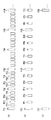
ここで、映像送信装置たるインターホン親機1から受け取った映像データは、図3(a)に示すように一定の時間間隔T0で並ぶ複数のIフレームFI1,FI2,…の間に所定数(図示例では5つ)のPフレームFP11〜FP15,FP21〜FP25,…が挿入されて構成されており、本来であれば、そのままネットワークインタフェース部40から送出して中継するのであるが、図3(b),(c)に示すようにIフレームFI2,FI4,…及びPフレームFPを間引いくことで中継する映像データのデータ量を減らすことができる。つまり、図3(a)に示すパターン(以下、「標準パターン」と呼ぶ。)のデータ量が最も多く且つ高画質となり、図3(b)に示すパターン(以下、「第1の間引きパターン」と呼ぶ。)のデータ量が2番目に多く且つ中程度の画質となり、図3(c)に示すパターン(以下、「第2の間引きパターン」と呼ぶ。)のデータ量が最も少なく且つ低画質となる。なお、第1の間引きパターンは、一つおきにIフレームFI2,FI4,…を間引くとともに間引いたIフレームFI2,FI4,…とその直前のIフレームFI1,FI3,…との間に挿入されていたPフレームFP11〜FP15,FP31〜FP35,…を、残ったIフレームFI1,FI3,FI5,…の間に等間隔で再配置したものである。また、第2の間引きパターンは、4つおきにIフレームFI2〜FI5を間引くとともに全てのPフレームFP11,…を間引いたものである。
Here, the video data received from the
而して、映像送信装置たるインターホン親機1から受け取った映像データを、映像受信装置たるインターホン副親機2B,2Cに中継するに当たり、中継装置4の制御部41は、メモリに記憶している各インターホン副親機2B,2Cの受信能力や処理能力を示す情報を参照し、例えば、受信能力や処理能力が相対的に高い映像受信装置(例えば、インターホン副親機2B)に対しては、図3(a)に示す標準パターン若しくは図3(B)に示す第1の間引きパターンで映像データを送信(中継)し、受信能力や処理能力が相対的に低い映像受信装置(例えば、無線インターホン副親機2C)に対しては、図3(c)に示す第2の間引きパターンで映像データを送信(中継)する。このようにすれば、それぞれの映像受信装置(インターホン副親機2B,2C)の受信能力や処理能力などに応じた適切なデータ量の映像データを送信することができ、映像データのデータ量を固定した場合と比較して伝送効率を向上することができる。なお、データ量を増減するための間引きパターンは上述のものに限定する必要はない。
Thus, when relaying the video data received from the
1 映像送信装置(インターホン親機)
2A,2B,2C 映像受信装置(インターホン副親機)
4 中継装置
20 制御部
21 ネットワークインタフェース部
22 映像伸長処理部
23 D/A変換部
24 映像表示部
40 ネットワークインタフェース部
41 制御部
42 映像圧縮処理部
1 Video transmission device (interphone master unit)
2A, 2B, 2C Video receiver (interphone secondary master unit)
4
Claims (1)
中継装置は、映像送信装置から受け取った映像データを圧縮する映像圧縮手段と、映像圧縮手段で圧縮された映像データを映像受信装置へ送信する送信手段と、送信手段から各伝送路への映像データの送信手順を制御する制御手段とを備え、
映像受信装置は、前記伝送路を介して映像データを受信する受信手段と、受信した映像データを伸長する映像伸長手段と、伸長された映像データを表示する映像表示手段と、前記受信手段並びに映像伸長手段による映像データの受信能力及び伸張処理能力を示す情報を中継装置に通知する制御手段とを備え、
中継装置の制御手段は、映像受信装置から通知された前記情報に応じて当該伝送路を介して送信する映像データのデータ量を増減することを特徴とする映像伝送システム。 One or more video transmission devices that transmit video data of a moving image via a transmission path, a plurality of video reception devices that receive video data transmitted via the transmission path, and provided in the middle of the transmission path A video transmission system including a relay device that relays video data transmitted from the video transmission device to one or more video reception devices;
The relay device includes a video compression unit that compresses video data received from the video transmission device, a transmission unit that transmits the video data compressed by the video compression unit to the video reception device, and video data from the transmission unit to each transmission path. Control means for controlling the transmission procedure of
The video receiver includes a receiving unit that receives video data via the transmission path, a video expansion unit that expands the received video data, a video display unit that displays the expanded video data, the reception unit, and the video Control means for notifying the relay device of information indicating the video data reception ability and decompression processing ability by the decompression means,
The video transmission system characterized in that the control means of the relay device increases or decreases the data amount of the video data to be transmitted through the transmission path according to the information notified from the video reception device.
Priority Applications (1)
| Application Number | Priority Date | Filing Date | Title |
|---|---|---|---|
| JP2007220290A JP2009055366A (en) | 2007-08-27 | 2007-08-27 | Video transmission system |
Applications Claiming Priority (1)
| Application Number | Priority Date | Filing Date | Title |
|---|---|---|---|
| JP2007220290A JP2009055366A (en) | 2007-08-27 | 2007-08-27 | Video transmission system |
Publications (1)
| Publication Number | Publication Date |
|---|---|
| JP2009055366A true JP2009055366A (en) | 2009-03-12 |
Family
ID=40506021
Family Applications (1)
| Application Number | Title | Priority Date | Filing Date |
|---|---|---|---|
| JP2007220290A Pending JP2009055366A (en) | 2007-08-27 | 2007-08-27 | Video transmission system |
Country Status (1)
| Country | Link |
|---|---|
| JP (1) | JP2009055366A (en) |
Citations (2)
| Publication number | Priority date | Publication date | Assignee | Title |
|---|---|---|---|---|
| JPH11161571A (en) * | 1997-11-27 | 1999-06-18 | Fujitsu Ltd | Adaptive transmission control system |
| JP2003348556A (en) * | 2002-05-29 | 2003-12-05 | Hitachi Ltd | Video telephone system and terminal device thereof |
-
2007
- 2007-08-27 JP JP2007220290A patent/JP2009055366A/en active Pending
Patent Citations (2)
| Publication number | Priority date | Publication date | Assignee | Title |
|---|---|---|---|---|
| JPH11161571A (en) * | 1997-11-27 | 1999-06-18 | Fujitsu Ltd | Adaptive transmission control system |
| JP2003348556A (en) * | 2002-05-29 | 2003-12-05 | Hitachi Ltd | Video telephone system and terminal device thereof |
Similar Documents
| Publication | Publication Date | Title |
|---|---|---|
| US7961653B2 (en) | Relay apparatus and communication system | |
| JP4258435B2 (en) | Intercom device and intercom system using the same | |
| JP5285392B2 (en) | Data transmission method and data transmission system | |
| JP2009055362A (en) | Video transmitter | |
| JP5199621B2 (en) | Video transmission device | |
| JP2009055367A (en) | Video transmission system | |
| JP5330661B2 (en) | Intercom base unit | |
| JP2009055368A (en) | Video transmission system | |
| JP2003134268A (en) | Local communication system | |
| JP4426745B2 (en) | On-premises communication system | |
| JP2009055366A (en) | Video transmission system | |
| JP2008252271A (en) | Video door intercom system | |
| JP2009055361A (en) | Video transmitter | |
| JP5266000B2 (en) | Intercom device | |
| JP4981585B2 (en) | Video transmission system relay device | |
| JP4888279B2 (en) | Video transmission device | |
| JP4981584B2 (en) | Video transmission system relay device | |
| JP2009055358A (en) | Repeater of video transmission system | |
| JP2009055360A (en) | Video transmitter | |
| JP2011055103A (en) | Condominium intercom system | |
| JP2010011218A (en) | Intercom system and monitor camera system | |
| JP2003032375A (en) | Interphone system | |
| JP2008131297A (en) | Image transfer device | |
| JP4429837B2 (en) | Switching device for remote monitoring | |
| JP2000253400A (en) | Image data conversion communication system |
Legal Events
| Date | Code | Title | Description |
|---|---|---|---|
| A621 | Written request for application examination |
Free format text: JAPANESE INTERMEDIATE CODE: A621 Effective date: 20100615 |
|
| A131 | Notification of reasons for refusal |
Free format text: JAPANESE INTERMEDIATE CODE: A131 Effective date: 20110830 |
|
| A02 | Decision of refusal |
Effective date: 20120110 Free format text: JAPANESE INTERMEDIATE CODE: A02 |
|
| A711 | Notification of change in applicant |
Free format text: JAPANESE INTERMEDIATE CODE: A712 Effective date: 20120112 |