JP2009052807A - Low-temperature air liquefaction separation device and its operation method - Google Patents
Low-temperature air liquefaction separation device and its operation method Download PDFInfo
- Publication number
- JP2009052807A JP2009052807A JP2007220015A JP2007220015A JP2009052807A JP 2009052807 A JP2009052807 A JP 2009052807A JP 2007220015 A JP2007220015 A JP 2007220015A JP 2007220015 A JP2007220015 A JP 2007220015A JP 2009052807 A JP2009052807 A JP 2009052807A
- Authority
- JP
- Japan
- Prior art keywords
- air
- heat exchanger
- raw material
- production operation
- material air
- Prior art date
- Legal status (The legal status is an assumption and is not a legal conclusion. Google has not performed a legal analysis and makes no representation as to the accuracy of the status listed.)
- Granted
Links
Images


Classifications
-
- F—MECHANICAL ENGINEERING; LIGHTING; HEATING; WEAPONS; BLASTING
- F25—REFRIGERATION OR COOLING; COMBINED HEATING AND REFRIGERATION SYSTEMS; HEAT PUMP SYSTEMS; MANUFACTURE OR STORAGE OF ICE; LIQUEFACTION SOLIDIFICATION OF GASES
- F25J—LIQUEFACTION, SOLIDIFICATION OR SEPARATION OF GASES OR GASEOUS OR LIQUEFIED GASEOUS MIXTURES BY PRESSURE AND COLD TREATMENT OR BY BRINGING THEM INTO THE SUPERCRITICAL STATE
- F25J3/00—Processes or apparatus for separating the constituents of gaseous or liquefied gaseous mixtures involving the use of liquefaction or solidification
- F25J3/02—Processes or apparatus for separating the constituents of gaseous or liquefied gaseous mixtures involving the use of liquefaction or solidification by rectification, i.e. by continuous interchange of heat and material between a vapour stream and a liquid stream
- F25J3/04—Processes or apparatus for separating the constituents of gaseous or liquefied gaseous mixtures involving the use of liquefaction or solidification by rectification, i.e. by continuous interchange of heat and material between a vapour stream and a liquid stream for air
- F25J3/04006—Providing pressurised feed air or process streams within or from the air fractionation unit
- F25J3/04012—Providing pressurised feed air or process streams within or from the air fractionation unit by compression of warm gaseous streams; details of intake or interstage cooling
- F25J3/04024—Providing pressurised feed air or process streams within or from the air fractionation unit by compression of warm gaseous streams; details of intake or interstage cooling of purified feed air, so-called boosted air
-
- F—MECHANICAL ENGINEERING; LIGHTING; HEATING; WEAPONS; BLASTING
- F25—REFRIGERATION OR COOLING; COMBINED HEATING AND REFRIGERATION SYSTEMS; HEAT PUMP SYSTEMS; MANUFACTURE OR STORAGE OF ICE; LIQUEFACTION SOLIDIFICATION OF GASES
- F25J—LIQUEFACTION, SOLIDIFICATION OR SEPARATION OF GASES OR GASEOUS OR LIQUEFIED GASEOUS MIXTURES BY PRESSURE AND COLD TREATMENT OR BY BRINGING THEM INTO THE SUPERCRITICAL STATE
- F25J3/00—Processes or apparatus for separating the constituents of gaseous or liquefied gaseous mixtures involving the use of liquefaction or solidification
- F25J3/02—Processes or apparatus for separating the constituents of gaseous or liquefied gaseous mixtures involving the use of liquefaction or solidification by rectification, i.e. by continuous interchange of heat and material between a vapour stream and a liquid stream
- F25J3/04—Processes or apparatus for separating the constituents of gaseous or liquefied gaseous mixtures involving the use of liquefaction or solidification by rectification, i.e. by continuous interchange of heat and material between a vapour stream and a liquid stream for air
- F25J3/04151—Purification and (pre-)cooling of the feed air; recuperative heat-exchange with product streams
- F25J3/04187—Cooling of the purified feed air by recuperative heat-exchange; Heat-exchange with product streams
- F25J3/04218—Parallel arrangement of the main heat exchange line in cores having different functions, e.g. in low pressure and high pressure cores
- F25J3/04224—Cores associated with a liquefaction or refrigeration cycle
-
- F—MECHANICAL ENGINEERING; LIGHTING; HEATING; WEAPONS; BLASTING
- F25—REFRIGERATION OR COOLING; COMBINED HEATING AND REFRIGERATION SYSTEMS; HEAT PUMP SYSTEMS; MANUFACTURE OR STORAGE OF ICE; LIQUEFACTION SOLIDIFICATION OF GASES
- F25J—LIQUEFACTION, SOLIDIFICATION OR SEPARATION OF GASES OR GASEOUS OR LIQUEFIED GASEOUS MIXTURES BY PRESSURE AND COLD TREATMENT OR BY BRINGING THEM INTO THE SUPERCRITICAL STATE
- F25J3/00—Processes or apparatus for separating the constituents of gaseous or liquefied gaseous mixtures involving the use of liquefaction or solidification
- F25J3/02—Processes or apparatus for separating the constituents of gaseous or liquefied gaseous mixtures involving the use of liquefaction or solidification by rectification, i.e. by continuous interchange of heat and material between a vapour stream and a liquid stream
- F25J3/04—Processes or apparatus for separating the constituents of gaseous or liquefied gaseous mixtures involving the use of liquefaction or solidification by rectification, i.e. by continuous interchange of heat and material between a vapour stream and a liquid stream for air
- F25J3/04248—Generation of cold for compensating heat leaks or liquid production, e.g. by Joule-Thompson expansion
- F25J3/04284—Generation of cold for compensating heat leaks or liquid production, e.g. by Joule-Thompson expansion using internal refrigeration by open-loop gas work expansion, e.g. of intermediate or oxygen enriched (waste-)streams
- F25J3/0429—Generation of cold for compensating heat leaks or liquid production, e.g. by Joule-Thompson expansion using internal refrigeration by open-loop gas work expansion, e.g. of intermediate or oxygen enriched (waste-)streams of feed air, e.g. used as waste or product air or expanded into an auxiliary column
- F25J3/04296—Claude expansion, i.e. expanded into the main or high pressure column
-
- F—MECHANICAL ENGINEERING; LIGHTING; HEATING; WEAPONS; BLASTING
- F25—REFRIGERATION OR COOLING; COMBINED HEATING AND REFRIGERATION SYSTEMS; HEAT PUMP SYSTEMS; MANUFACTURE OR STORAGE OF ICE; LIQUEFACTION SOLIDIFICATION OF GASES
- F25J—LIQUEFACTION, SOLIDIFICATION OR SEPARATION OF GASES OR GASEOUS OR LIQUEFIED GASEOUS MIXTURES BY PRESSURE AND COLD TREATMENT OR BY BRINGING THEM INTO THE SUPERCRITICAL STATE
- F25J3/00—Processes or apparatus for separating the constituents of gaseous or liquefied gaseous mixtures involving the use of liquefaction or solidification
- F25J3/02—Processes or apparatus for separating the constituents of gaseous or liquefied gaseous mixtures involving the use of liquefaction or solidification by rectification, i.e. by continuous interchange of heat and material between a vapour stream and a liquid stream
- F25J3/04—Processes or apparatus for separating the constituents of gaseous or liquefied gaseous mixtures involving the use of liquefaction or solidification by rectification, i.e. by continuous interchange of heat and material between a vapour stream and a liquid stream for air
- F25J3/04248—Generation of cold for compensating heat leaks or liquid production, e.g. by Joule-Thompson expansion
- F25J3/04284—Generation of cold for compensating heat leaks or liquid production, e.g. by Joule-Thompson expansion using internal refrigeration by open-loop gas work expansion, e.g. of intermediate or oxygen enriched (waste-)streams
- F25J3/0429—Generation of cold for compensating heat leaks or liquid production, e.g. by Joule-Thompson expansion using internal refrigeration by open-loop gas work expansion, e.g. of intermediate or oxygen enriched (waste-)streams of feed air, e.g. used as waste or product air or expanded into an auxiliary column
- F25J3/04303—Lachmann expansion, i.e. expanded into oxygen producing or low pressure column
-
- F—MECHANICAL ENGINEERING; LIGHTING; HEATING; WEAPONS; BLASTING
- F25—REFRIGERATION OR COOLING; COMBINED HEATING AND REFRIGERATION SYSTEMS; HEAT PUMP SYSTEMS; MANUFACTURE OR STORAGE OF ICE; LIQUEFACTION SOLIDIFICATION OF GASES
- F25J—LIQUEFACTION, SOLIDIFICATION OR SEPARATION OF GASES OR GASEOUS OR LIQUEFIED GASEOUS MIXTURES BY PRESSURE AND COLD TREATMENT OR BY BRINGING THEM INTO THE SUPERCRITICAL STATE
- F25J3/00—Processes or apparatus for separating the constituents of gaseous or liquefied gaseous mixtures involving the use of liquefaction or solidification
- F25J3/02—Processes or apparatus for separating the constituents of gaseous or liquefied gaseous mixtures involving the use of liquefaction or solidification by rectification, i.e. by continuous interchange of heat and material between a vapour stream and a liquid stream
- F25J3/04—Processes or apparatus for separating the constituents of gaseous or liquefied gaseous mixtures involving the use of liquefaction or solidification by rectification, i.e. by continuous interchange of heat and material between a vapour stream and a liquid stream for air
- F25J3/04248—Generation of cold for compensating heat leaks or liquid production, e.g. by Joule-Thompson expansion
- F25J3/04375—Details relating to the work expansion, e.g. process parameter etc.
- F25J3/04393—Details relating to the work expansion, e.g. process parameter etc. using multiple or multistage gas work expansion
-
- F—MECHANICAL ENGINEERING; LIGHTING; HEATING; WEAPONS; BLASTING
- F25—REFRIGERATION OR COOLING; COMBINED HEATING AND REFRIGERATION SYSTEMS; HEAT PUMP SYSTEMS; MANUFACTURE OR STORAGE OF ICE; LIQUEFACTION SOLIDIFICATION OF GASES
- F25J—LIQUEFACTION, SOLIDIFICATION OR SEPARATION OF GASES OR GASEOUS OR LIQUEFIED GASEOUS MIXTURES BY PRESSURE AND COLD TREATMENT OR BY BRINGING THEM INTO THE SUPERCRITICAL STATE
- F25J3/00—Processes or apparatus for separating the constituents of gaseous or liquefied gaseous mixtures involving the use of liquefaction or solidification
- F25J3/02—Processes or apparatus for separating the constituents of gaseous or liquefied gaseous mixtures involving the use of liquefaction or solidification by rectification, i.e. by continuous interchange of heat and material between a vapour stream and a liquid stream
- F25J3/04—Processes or apparatus for separating the constituents of gaseous or liquefied gaseous mixtures involving the use of liquefaction or solidification by rectification, i.e. by continuous interchange of heat and material between a vapour stream and a liquid stream for air
- F25J3/04406—Processes or apparatus for separating the constituents of gaseous or liquefied gaseous mixtures involving the use of liquefaction or solidification by rectification, i.e. by continuous interchange of heat and material between a vapour stream and a liquid stream for air using a dual pressure main column system
- F25J3/04412—Processes or apparatus for separating the constituents of gaseous or liquefied gaseous mixtures involving the use of liquefaction or solidification by rectification, i.e. by continuous interchange of heat and material between a vapour stream and a liquid stream for air using a dual pressure main column system in a classical double column flowsheet, i.e. with thermal coupling by a main reboiler-condenser in the bottom of low pressure respectively top of high pressure column
-
- F—MECHANICAL ENGINEERING; LIGHTING; HEATING; WEAPONS; BLASTING
- F25—REFRIGERATION OR COOLING; COMBINED HEATING AND REFRIGERATION SYSTEMS; HEAT PUMP SYSTEMS; MANUFACTURE OR STORAGE OF ICE; LIQUEFACTION SOLIDIFICATION OF GASES
- F25J—LIQUEFACTION, SOLIDIFICATION OR SEPARATION OF GASES OR GASEOUS OR LIQUEFIED GASEOUS MIXTURES BY PRESSURE AND COLD TREATMENT OR BY BRINGING THEM INTO THE SUPERCRITICAL STATE
- F25J3/00—Processes or apparatus for separating the constituents of gaseous or liquefied gaseous mixtures involving the use of liquefaction or solidification
- F25J3/02—Processes or apparatus for separating the constituents of gaseous or liquefied gaseous mixtures involving the use of liquefaction or solidification by rectification, i.e. by continuous interchange of heat and material between a vapour stream and a liquid stream
- F25J3/04—Processes or apparatus for separating the constituents of gaseous or liquefied gaseous mixtures involving the use of liquefaction or solidification by rectification, i.e. by continuous interchange of heat and material between a vapour stream and a liquid stream for air
- F25J3/04763—Start-up or control of the process; Details of the apparatus used
- F25J3/04769—Operation, control and regulation of the process; Instrumentation within the process
- F25J3/04812—Different modes, i.e. "runs" of operation
- F25J3/04836—Variable air feed, i.e. "load" or product demand during specified periods, e.g. during periods with high respectively low power costs
-
- F—MECHANICAL ENGINEERING; LIGHTING; HEATING; WEAPONS; BLASTING
- F25—REFRIGERATION OR COOLING; COMBINED HEATING AND REFRIGERATION SYSTEMS; HEAT PUMP SYSTEMS; MANUFACTURE OR STORAGE OF ICE; LIQUEFACTION SOLIDIFICATION OF GASES
- F25J—LIQUEFACTION, SOLIDIFICATION OR SEPARATION OF GASES OR GASEOUS OR LIQUEFIED GASEOUS MIXTURES BY PRESSURE AND COLD TREATMENT OR BY BRINGING THEM INTO THE SUPERCRITICAL STATE
- F25J2240/00—Processes or apparatus involving steps for expanding of process streams
- F25J2240/40—Expansion without extracting work, i.e. isenthalpic throttling, e.g. JT valve, regulating valve or venturi, or isentropic nozzle, e.g. Laval
- F25J2240/42—Expansion without extracting work, i.e. isenthalpic throttling, e.g. JT valve, regulating valve or venturi, or isentropic nozzle, e.g. Laval the fluid being air
-
- F—MECHANICAL ENGINEERING; LIGHTING; HEATING; WEAPONS; BLASTING
- F25—REFRIGERATION OR COOLING; COMBINED HEATING AND REFRIGERATION SYSTEMS; HEAT PUMP SYSTEMS; MANUFACTURE OR STORAGE OF ICE; LIQUEFACTION SOLIDIFICATION OF GASES
- F25J—LIQUEFACTION, SOLIDIFICATION OR SEPARATION OF GASES OR GASEOUS OR LIQUEFIED GASEOUS MIXTURES BY PRESSURE AND COLD TREATMENT OR BY BRINGING THEM INTO THE SUPERCRITICAL STATE
- F25J2245/00—Processes or apparatus involving steps for recycling of process streams
- F25J2245/40—Processes or apparatus involving steps for recycling of process streams the recycled stream being air
Abstract
Description
本発明は、深冷空気液化分離装置およびその運転方法に係り、より詳しくは、窒素、酸素ガス等を製造するガス製造運転から液体窒素、酸素等を製造する液製造運転に切換えるに際して、液化熱交換器の再冷却運転を行う必要がなく、切換え開始後短時間のうちに液製造運転に移行することを可能ならしめる深冷空気液化分離装置およびその運転方法に関するものである。 The present invention relates to a cryogenic air liquefaction separation apparatus and an operation method thereof, and more specifically, when switching from a gas production operation for producing nitrogen, oxygen gas or the like to a liquid production operation for producing liquid nitrogen, oxygen or the like, The present invention relates to a chilled air liquefaction separation apparatus and a method for operating the same, which makes it possible to shift to a liquid production operation in a short time after the start of switching without performing a recooling operation of the exchanger.
鉄鋼業等の酸素や窒素を大量に消費する工業分野においては、酸素や窒素の供給源として深冷空気液化分離装置が使用されている。このような深冷空気液化分離装置の中に、電力コストが高い昼間には窒素、酸素ガス等を製造するガス製造運転を行う一方、電力コストが安い夜間になると切換えて、液体窒素、酸素等を製造する液製造運転に移行できるようにした深冷空気液化分離装置がある。 In the industrial field that consumes a large amount of oxygen and nitrogen such as in the steel industry, a cryogenic air liquefaction separation apparatus is used as a supply source of oxygen and nitrogen. In such a cryogenic air liquefaction separation device, gas production operation to produce nitrogen, oxygen gas, etc. is performed during the daytime when the power cost is high, while switching to liquid nitrogen, oxygen, etc. at night when the power cost is low There is a chilled air liquefaction separation device that can be shifted to a liquid production operation for producing a liquid.
以下、従来例に係る一般的な液化装置付きの深冷空気液化分離装置を、その系統図の図5を参照しながら説明する。即ち、一般的な液化装置付きの深冷空気液化分離装置は、空気ろ過器51から吸込まれ、原料空気圧縮機52で圧縮されると共に、水洗冷却塔53で冷却された原料空気と、精留塔55から出た製品窒素と製品酸素とを熱交換させる熱交換器(以下、主熱交換器という)54と、液化装置63とを備えている。この液化装置63は、前記精留塔55から出て主熱交換器54で常温に戻された製品窒素の一部を昇圧するための循環窒素圧縮機62、昇圧された窒素を液化するための熱交換器67、前記精留塔55から出て主熱交換器54で常温に戻されると共に、酸素圧縮機61で圧縮された製品酸素の一部を液化するための熱交換器77、寒冷を発生するための膨張タービン72,73等から構成されている。
Hereinafter, a general cold air liquefaction separation apparatus with a liquefaction apparatus according to a conventional example will be described with reference to FIG. That is, a general cryogenic air liquefaction separation apparatus with a liquefier is sucked from an
このような液化装置付きの深冷空気液化分離装置は、精留塔55から主熱交換器54を通って排出されるガス酸素、ガス窒素の一部を、液化装置63を起動することによって液化して、液体酸素と、液体窒素を製造している。液化装置63の起動とは、循環窒素圧縮機62、膨張タービン72,73の起動、および熱交換器67,77における熱交換の開始を意味する。この特性を利用して、電力コストが安い夜間は循環窒素圧縮機62を起動してガス酸素、ガス窒素の一部を液化備蓄し、電力コストが高い昼間は循環窒素圧縮機62の運転を停止してガス製品のみを製造する運転を行っている。また、熱交換器67,77は、液化装置63が運転されていない昼間では、次の運転のために低温状態に保持された待機状態になっている。
Such a chilled air liquefaction separation apparatus with a liquefaction device liquefies a part of gaseous oxygen and gaseous nitrogen discharged from the
ところで、液化装置63の膨張タービン72,73にオイルベアリング式の軸受が使用されている場合には、運転中は軸受の温度上昇を防止するために、軸受用のオイルを軸受とオイルクーラーとの間で循環させて軸受の温度上昇を防止している。また、液化装置63の運転停止中においても、オイルが固化したりしないように軸受用のオイルを軸受とオイルクーラーとの間で循環させて軸受の温度低下を防止するようにしている。ところが、膨張タービン72,73の運転停止中においても液化装置63が低温状態に保持されているため、特に冷却水の温度が低い冬季では、軸受の温度が次第に低下し、これに伴ってオイルの温度も相当低下する。この状態で運転すると、軸受にかじりが生じたり、振動が発生したりするため、膨張タービン72や73を起動するに際して、オイルや軸受を所定の温度になるまで加温する必要がある。
By the way, when oil bearing type bearings are used for the
そのため、液化装置63の膨張タービン72,73を起動する際には、予め低負荷状態による暖気運転を行い、オイルや軸受が所定の温度になるまで加温していた。この暖気運転の所要時間は、冷却水の温度、停止時間、あるいはタービンの大きさ等により相違するが、1時間かかることもあるため、ガスの液化ができないのに加えて、循環窒素圧縮機の運転に要する電力が無駄になるという問題があった。そこで、水洗冷却塔から導出される加温された約50℃の温排水をオイルクーラーに導入してオイルを約30℃に加温し、加温したオイルを軸受けに導入して軸受を加温した後に、膨張タービン72,73を起動するようにしている。この場合、温排水を利用するため、初期設備コストを要するものの、ランニングコストがほとんど掛からないという利点がある。また、これにより、膨張タービン72,73の起動に要する所要時間を大幅に短縮できると記載されている(例えば、特許文献1参照)。
上記従来例に係る液化装置付きの深冷空気液化分離装置によれば、タービンの起動時間の短縮により、ガス製造運転から液製造運転への移行時間が短縮されるため、それなりに優れていると考えられる。しかしながら、この従来例に係る液化装置付きの深冷空気液化分離装置には後述するような解決すべき課題がある。 According to the cryogenic air liquefaction separation apparatus with a liquefier according to the above conventional example, the transition time from the gas production operation to the liquid production operation is shortened by shortening the startup time of the turbine. Conceivable. However, the cryogenic air liquefaction separation apparatus with a liquefier according to this conventional example has problems to be solved as described later.
上記従来例に係る液化装置付きの深冷空気液化分離装置では、運転停止中の液化装置は低温状態に保持される。しかしながら、外部からの入熱を完全に遮断することはほぼ不可能であり、10〜14時間に及ぶ昼間の運転停止中に、外部からの入熱により熱交換器の温度が数十℃は上昇する。また、熱交換器内での熱伝導により、通常運転時は常温である温端側が、運転停止中にマイナス数十℃に冷却される。 In the chilled air liquefaction separation apparatus with a liquefier according to the above-described conventional example, the liquefier that is not operating is kept in a low temperature state. However, it is almost impossible to completely shut off the heat input from the outside, and the heat exchanger temperature increases by several tens of degrees Celsius due to heat input from the outside during the daytime shutdown for 10 to 14 hours. To do. Also, due to heat conduction in the heat exchanger, the warm end side, which is normal temperature during normal operation, is cooled to minus several tens of degrees Celsius during operation stop.
このような状態で、液化装置が起動されるため、起動直後は低温流体が低温のまま放出され、常温ラインの配管が破損する可能性があるという問題、運転停止中における入熱により昇温した熱交換器を再冷却しなければならないという問題、および運転停止中における入熱による熱交換器の膨張と収縮の繰り返し、つまり熱ひずみの繰り返しにより熱交換器が疲労破損し、メンテナンスコストが嵩むという問題が残っている。前記熱交換器の再冷却所要時間は、季節、この液化装置の停止時間、熱交換器の大きさ(容量)等によって相違するが、およそ0.5から1.0時間である。従って、およそ0.5から1.0時間の熱交換器の再冷却運転中は液体窒素、酸素等を製造することができないから、好ましくない。 In such a state, since the liquefaction device is started, immediately after startup, the low temperature fluid is discharged at a low temperature, and there is a possibility that the piping of the normal temperature line may be damaged. The problem of having to re-cool the heat exchanger, and repeated heat expansion and contraction of the heat exchanger due to heat input during shutdown, that is, the heat exchanger fatigues due to repeated thermal strain, increasing maintenance costs The problem remains. The time required for recooling the heat exchanger is approximately 0.5 to 1.0 hour, although it varies depending on the season, the stop time of the liquefier, the size (capacity) of the heat exchanger, and the like. Accordingly, liquid nitrogen, oxygen, etc. cannot be produced during the recooling operation of the heat exchanger for about 0.5 to 1.0 hour, which is not preferable.
従って、本発明の目的は、窒素、酸素ガス等を製造するガス製造運転から液体窒素、酸素等を製造する液製造運転に切換えるに際して、熱交換器の再冷却運転を行う必要がなく、切換え時に低温流体が低温のまま常温ラインに放出されることもなく、熱交換器に繰り返し応力を与えることもなく、短時間のうちに液製造運転に移行することを可能ならしめる深冷空気液化分離装置およびその運転方法を提供することである。 Therefore, the object of the present invention is to eliminate the need for recooling operation of the heat exchanger when switching from the gas production operation for producing nitrogen, oxygen gas, etc. to the liquid production operation for producing liquid nitrogen, oxygen, etc. Cryogenic air liquefaction separation device that makes it possible to move to a liquid production operation in a short time without the low temperature fluid being discharged to the room temperature line at a low temperature and without repeatedly applying stress to the heat exchanger. And providing a method of operation thereof.
上記課題を解決するために、本発明の請求項1に係る深冷空気液化分離装置が採用した手段は、原料空気圧縮機と、この原料空気圧縮機で圧縮された原料空気を予冷する予冷ユニットと、この予冷ユニットで予冷された原料空気から水分・炭酸ガスを除去して精製する吸着塔ユニットと、この吸着塔ユニットで精製された原料空気の一部を冷却する主熱交換器と、前記吸着塔ユニットで精製された原料空気の残りを圧縮する昇圧圧縮機と、この昇圧圧縮機で昇圧された原料空気の一部を液化するための液化熱交換器と、前記昇圧圧縮機で圧縮された原料空気の残りの一部を膨張させて寒冷を発生させる高圧膨張タービンと、前記主熱交換器、液化熱交換器を経て導入された原料空気を窒素と酸素等に精留分離する複式精留塔と、これらに付随する付帯設備とを備えると共に、ガス製造運転と液製造運転とに切換え操作される深冷空気液化分離装置において、前記ガス製造運転中は開弁され、前記液製造運転中は閉弁される第1開閉弁が介装され、前記吸着塔ユニットで精製された原料空気の残りを前記液化熱交換器に導入する第1空気導入ラインと、前記ガス製造運転中は開弁され、前記液製造運転中は閉弁される第2開閉弁が介装され、前記液化熱交換器から出た原料空気を複式精留塔に導入する第2空気導入ラインと、前記ガス製造運転中は閉弁され、前記液製造運転中は開弁される第3開閉弁が介装され、前記高圧膨張タービンの圧縮機側から出た原料空気を前記液化熱交換器に導入する第3空気導入ラインと、前記ガス製造運転中は閉弁され、前記液製造運転中は開弁される第4開閉弁が介装され、前記液化熱交換器から出た原料空気を前記高圧膨張タービンの膨張機側に導入する第4空気導入ラインと、液製造運転に際して前記第4空気導入ラインから導入され、前記高圧膨張タービンの膨張機で膨張されて寒冷を発生した原料空気を複式精留塔に導入する第5空気導入ラインを備えたことを特徴とするものである。 In order to solve the above problems, the means adopted by the chilled air liquefaction separation apparatus according to claim 1 of the present invention includes a raw air compressor and a precooling unit for precooling the raw air compressed by the raw air compressor. An adsorption tower unit that removes moisture / carbon dioxide gas from the raw air precooled by the precooling unit, purifies the main heat exchanger that cools a part of the raw material air purified by the adsorption tower unit, A pressurizing compressor for compressing the remainder of the raw material air purified by the adsorption tower unit, a liquefied heat exchanger for liquefying a part of the raw air pressurized by the pressurizing compressor, and the pressurizing compressor A high-pressure expansion turbine that expands the remaining part of the raw material air to generate cold, and a double precision rectifier that separates the raw material air introduced through the main heat exchanger and the liquefied heat exchanger into nitrogen and oxygen. Towers and their accompanying A chilled air liquefaction separation device that is switched between a gas production operation and a liquid production operation, and is opened during the gas production operation and closed during the liquid production operation. A first air introduction line which is provided with one on-off valve and introduces the remainder of the raw material air purified by the adsorption tower unit to the liquefied heat exchanger, and is opened during the gas production operation, and the liquid production operation A second on-off valve that is closed inside is interposed, a second air introduction line that introduces raw air from the liquefied heat exchanger into the double rectification column, and is closed during the gas production operation, A third on-off valve that is opened during the liquid production operation is interposed, and a third air introduction line that introduces raw air that has come out from the compressor side of the high-pressure expansion turbine into the liquefied heat exchanger, and the gas The valve is closed during the manufacturing operation and is opened during the liquid manufacturing operation. A fourth open / close valve is interposed, and a fourth air introduction line for introducing the raw air discharged from the liquefied heat exchanger to the expander side of the high-pressure expansion turbine and a fourth air introduction line for the liquid production operation And a fifth air introduction line for introducing the raw material air, which has been expanded by the expander of the high-pressure expansion turbine and generates cold, into the double rectification column.
本発明の請求項2に係る深冷空気液化分離装置の運転方法が採用した手段は、原料空気を原料空気圧縮機で圧縮し、原料空気圧縮機から出た原料空気を予冷ユニットで予冷し、予冷した原料空気を水分・炭酸ガスを除去する吸着塔ユニットに導入し、この吸着塔ユニットから出た原料空気の一部を主熱交換器に導入し、残りの原料空気を液化熱交換器に導入すると共に、前記主熱交換器、および液化熱交換器から出た原料空気を複式精留塔に導入して窒素ガスと酸素ガス等を製造するガス製造運転と、前記吸着塔ユニットから出た原料空気の一部を主熱交換器に導入し、残りの原料空気を昇圧圧縮機で昇圧させた後に二分し、二分した一方の原料空気を液化熱交換器に導入し、二分した他方の原料空気を高圧膨張タービンの圧縮機で圧縮して液化熱交換器に導入し、この液化熱交換器から出た原料空気を高圧膨張タービンの膨張機で膨張させた後に複式精留塔に導入すると共に、前記主熱交換器から出た原料空気の一部、および前記液化熱交換器から出た二分した一方の原料空気を複式精留塔に導入して液体窒素と液体酸素等を製造する液製造運転とを自動切換することを特徴とするものである。
The means employed by the operation method of the chilled air liquefaction separation apparatus according to
本発明の請求項1に係る深冷空気液化分離装置、請求項2に係る深冷空気液化分離装置の運転方法では、深冷空気液化分離装置のガス製造運転においては、吸着塔ユニットで精製された原料空気の一部が主熱交換器に導入されると共に、主熱交換器から出た圧縮空気が複式精留塔に供給される。また、これと並行して、吸着塔ユニットで精製された原料空気の残りが第1空気導入ラインから液化熱交換器に導入され、この液化熱交換器から出た原料空気が第2空気導入ラインから複式精留塔に導入される。
In the operation method of the cryogenic air liquefaction separation apparatus according to claim 1 of the present invention and the cryogenic air liquefaction separation apparatus according to
一方、深冷空気液化分離装置の液製造運転においては、吸着塔ユニットで精製された原料空気の一部が主熱交換器に導入されると共に、この主熱交換器から出た圧縮空気が複式精留塔に供給される。また、これと並行して、昇圧圧縮機で圧縮された残りの原料空気の一部が液化熱交換器に導入され、この液化熱交換器を出た原料空気が複式精留塔に導入される。そして、昇圧圧縮機で圧縮された残りの原料空気の一部の残りが高圧膨張タービンの圧縮機側に導入され、この圧縮機側から出た原料空気が第3空気導入ラインから液化熱交換器に導入され、この液化熱交換器を出た原料空気が第4空気導入ラインから高圧膨張タービンの膨張機側に導入され、この高圧膨張タービンでの膨張により発生した寒冷が複式精留塔に導入される。 On the other hand, in the liquid manufacturing operation of the cryogenic air liquefaction separation apparatus, a part of the raw material air purified by the adsorption tower unit is introduced into the main heat exchanger, and the compressed air from the main heat exchanger is duplicated. Supplied to the rectification tower. In parallel with this, a part of the remaining raw material air compressed by the booster compressor is introduced into the liquefied heat exchanger, and the raw material air exiting this liquefied heat exchanger is introduced into the double rectification column. . A part of the remaining raw material air compressed by the booster compressor is introduced to the compressor side of the high-pressure expansion turbine, and the raw material air discharged from the compressor side is liquefied heat exchanger from the third air introduction line. The raw material air that has been introduced into the liquefied heat exchanger and introduced from the fourth air introduction line is introduced into the expander side of the high-pressure expansion turbine, and the cold generated by the expansion in the high-pressure expansion turbine is introduced into the double rectification column. Is done.
本発明の請求項1に係る深冷空気液化分離装置、請求項2に係る深冷空気液化分離装置の運転方法では、上記のとおり、ガス製造運転と液製造運転とが交互に繰り返されるのであるが、液化熱交換器は液製造運転中のみならず、ガス製造運転中も作動されるように構成されている。従って、本発明の請求項1に係る深冷空気液化分離装置、請求項2に係る深冷空気液化分離装置の運転方法によれば、下記のとおりの効果を得ることができる。
In the operation method of the cryogenic air liquefaction separation apparatus according to claim 1 of the present invention and the cryogenic air liquefaction separation apparatus according to
(1)ガス製造運転中の液化熱交換器のガス出入り口間の温度分布は、液製造運転中における温度分布とほぼ同等に保持されていて、ガス製造運転から液製造運転に切換えるに際して冷却運転をする必要がないため、極めて短時間のうちにガス製造運転中の深冷空気液化分離装置を液製造運転に移行させることができる。これにより、実質的な液製造運転時間が増加し、液体酸素・窒素等の生産性が向上するため、それら液体酸素・窒素等のコスト低減に大いに寄与することができる。
(2)ガス製造運転中の液化熱交換器のガス出入り口間の温度分布は、液製造運転中における温度分布とほぼ同等に保持されている。従って、温端側がマイナスの温度になっているということがなく、液製造運転への切換え時に低温流体が低温のまま放出されることがないため、常温ラインの配管が損傷するという危険性がない。
(3)液化熱交換器は収縮と膨張とを繰り返すことがないため、液化熱交換器の耐久寿命が向上する。
(1) The temperature distribution between the gas inlet and outlet of the liquefied heat exchanger during the gas production operation is maintained almost equal to the temperature distribution during the liquid production operation, and the cooling operation is performed when switching from the gas production operation to the liquid production operation. Therefore, the chilled air liquefaction separation apparatus during the gas production operation can be shifted to the liquid production operation in a very short time. Thereby, substantial liquid manufacturing operation time increases and productivity of liquid oxygen, nitrogen, etc. improves, Therefore It can contribute greatly to the cost reduction of these liquid oxygen, nitrogen, etc.
(2) The temperature distribution between the gas inlets and outlets of the liquefied heat exchanger during the gas production operation is maintained substantially equal to the temperature distribution during the liquid production operation. Therefore, there is no danger of damaging the piping of the room temperature line because the hot end side is not at a negative temperature and the low temperature fluid is not released at a low temperature when switching to the liquid production operation. .
(3) Since the liquefied heat exchanger does not repeat contraction and expansion, the durability life of the liquefied heat exchanger is improved.
また、本発明の請求項1に係る深冷空気液化分離装置によれば、液製造運転に際して、主熱交換器から出た原料空気の一部が複式精留塔に導入されるが、液製造運転に切換えられると、前記主熱交換器から出た原料空気の一部と共に、短時間のうちに高圧膨張タービンの膨張機で膨張されて寒冷を発生した原料空気が第5空気導入ラインを介して複式精留塔に導入される。従って、液製造運転への切換後、短時間のうちに効率よく液体窒素、液体酸素等を製造することができ、液製造運転のための稼動率が向上するから、低コストでより大量の液体窒素、液体酸素等を生産することができる。 Further, according to the chilled air liquefaction separation apparatus according to claim 1 of the present invention, part of the raw air discharged from the main heat exchanger is introduced into the double fractionator during the liquid production operation. When switched to operation, together with a part of the raw air that has come out of the main heat exchanger, the raw air that has been expanded in the expander of the high-pressure expansion turbine in a short period of time and has generated coldness passes through the fifth air introduction line. To be introduced into the double rectification column. Therefore, after switching to the liquid production operation, liquid nitrogen, liquid oxygen, etc. can be efficiently produced in a short time, and the operating rate for the liquid production operation is improved. Nitrogen, liquid oxygen, etc. can be produced.
以下、本発明の運転方法を実施する、実施の形態1乃至4に係る深冷空気液化分離装置を、その模式的系統図の図1乃至4を順次参照しながら説明する。先ず、本発明の実施の形態1に係る深冷空気液化分離装置を、その系統図の図1を参照しながら説明する。 Hereinafter, the cryogenic air liquefaction separation apparatus according to Embodiments 1 to 4 for carrying out the operation method of the present invention will be described with reference to FIGS. 1 to 4 of the schematic system diagrams. First, a cryogenic air liquefaction separation apparatus according to Embodiment 1 of the present invention will be described with reference to FIG.
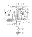
図1に示す符号1は、本発明の形態1に係る深冷空気液化分離装置であって、この本発明の形態1に係る深冷空気液化分離装置1は、主として、原料空気圧縮機2と、予冷ユニット3aと、吸着塔ユニット3bと、主熱交換器4と、昇圧圧縮機9bと、液化熱交換器7と、高圧膨張タービン12と、複式精留塔15と、これらに付随する付帯設備とから構成されている。
Reference numeral 1 shown in FIG. 1 is a chilled air liquefaction separation apparatus according to Embodiment 1 of the present invention. The chilled air liquefaction separation apparatus 1 according to Embodiment 1 of the present invention mainly includes a raw
より詳しくは、深冷空気液化分離装置1は、原料空気圧縮機2で圧縮された原料空気を、主熱交換器4や液化熱交換器7に供給する空気供給元ライン3を備えている。この空気供給元ライン3には、原料空気圧縮機2側から下流側に向って順に、この原料空気圧縮機2で圧縮された原料空気を予冷するための予冷ユニット3aが介装されると共に、この予冷ユニット3aで10〜40℃に予冷された原料空気から水分・炭酸ガスを除去して精製する吸着塔ユニット3bが介装されている。この吸着塔ユニット3bは、交互に使用される第1吸着塔3b1と、第2吸着塔3b2とが並列に配設されてなる構成になっている。
なお、水分・炭酸ガスを除去するために、例えば第1吸着塔3b1に原料空気が導入されている間に、第2吸着塔3b2の吸着剤を再生するために、この第2吸着塔3b2には、図示しないヒータで加熱したパージガスが供給され、水分・炭酸ガスを吸着した吸着剤が再生されるように構成されている。
More specifically, the chilled air liquefaction separation apparatus 1 includes an air
In order to remove moisture / carbon dioxide gas, for example, this second adsorption tower is used to regenerate the adsorbent of the
前記空気供給元ライン3の吸着塔ユニット3bより先端側は、主熱交換器4に連通しており、前記吸着塔ユニット3bにより精製された原料空気の一部が主熱交換器4に導入されるように構成されている。そして、前記主熱交換器4の出口から、上部塔15aと下部塔15bとからなる複式精留塔15の前記下部塔15bに空気供給先ライン5が連通しており、前記空気供給元ライン3から導入されて液化点付近の温度になるまで冷却された原料空気が下部塔15bに導入されるようになっている。
The front end side of the
前記空気供給元ライン3の吸着塔ユニット3bと主熱交換器4との間から、液化熱交換器7に連通する第1空気導入ライン6が分岐している。この第1空気導入ライン6には、ガス製造運転中は開弁され、液製造運転中は閉弁される第1開閉弁V1が介装されており、前記吸着塔ユニット3bで精製された原料空気の残り(前記吸着塔ユニット3bから出た原料空気から前記主熱交換器4に導入された原料空気を差し引いた量)が液化熱交換器7に導入されるようになっている。そして、前記液化熱交換器7の出口から前記空気供給先ライン5の前記主熱交換器5と前記下部塔15bとの間に、第2空気導入ライン8が連通している。この第2空気導入ライン8には、ガス製造運転中は開弁され、液製造運転中は閉弁される第2開閉弁V2が介装されており、前記第1空気導入ライン6から導入された原料空気が液化点近傍の温度になるまで冷却されて下部塔15bに導入されるようになっている。
A first
前記第1空気導入ライン6の空気供給元ライン3との分岐部と、前記第1開閉弁V1との間から、液化熱交換器7に連通する空気導入元ライン9が分岐している。この空気導入元ライン9には、分岐側から液化熱交換器7に向って順に、入側開閉弁9aと、この入側開閉弁9aを通過した原料空気を3.0MPaGまで昇圧させる昇圧圧縮機9bが介装されている。そして、液化熱交換器7から前記下部塔15bの前記空気供給先ライン5の連通位置の上側に、出側開閉弁10aが介装され、前記空気導入元ライン9から導入されると共に、液化熱交換器7により冷却されて液化した原料空気を導入する空気導入先ライン10が連通している。
An air
前記空気導入元ライン9の昇圧圧縮機9bと、前記液化熱交換器7との間から第3空気導入ライン11が分岐しており、この第3空気導入ライン11は高圧膨張タービン12の圧縮機12aを介して、前記第1空気導入ライン6の第1開閉弁V1と液化熱交換器7との間に連通している。この第3空気導入ライン11の圧縮機12a側と、第1空気導入ライン6の連通部との間に、ガス製造運転中は閉弁され、液製造運転中は開弁される第3開閉弁V3が介装されており、圧縮機12aで約5.0MPaGまで昇圧された後、液化熱交換器7に導入されるようになっている。
A third
前記第1空気導入ライン6から導入された原料空気を前記第2空気導入ライン8に導く液化熱交換器7内の熱交換流路7aの途中から、高圧膨張タービン12の膨張機12bに連通する第4空気導入ライン13が分岐している。この第4空気導入ライン13には、ガス製造運転中は閉弁され、液製造運転中は開弁される第4開閉弁V4が介装されている。
そして、前記高圧膨張タービン12の膨張機12bの出口は、第5空気導入ライン14を介して前記空気供給先ライン5の前記第2空気導入ライン8の連通部と下部塔15bとの間に連通している。そのため、液化熱交換器7で約−100℃に冷却された原料空気が前記第4空気導入ライン13から導入されると、前記膨張機12bで約0.45MPaGまで膨張されて寒冷を発生した原料空気が第5空気導入ライン14を介して下部塔15bに導入される。なお、前記第1開閉弁V1、第2開閉弁V2、第3開閉弁V3、第4開閉弁V4、入側開閉弁9a、および出側開閉弁10aは、ガス製造運転と、液製造運転の切換えに際して、遠隔操作により開閉操作される自動開閉弁である。
The raw material air introduced from the first
The outlet of the
前記複式精留塔15の下部塔15bの頂部に液体窒素供給ライン16が設けられると共に、前記複式精留塔15の上部塔15aの底部に液体酸素供給ライン17が設けられている。また、前記複式精留塔15の上部塔15aの頂部に窒素ガス供給ライン18が、下部に酸素ガス供給ライン19が設けられると共に、上下方向の中程より上方位置に廃ガス排出ライン18aが設けられている。なお、複式精留塔15の上部塔15aの直下であって、かつ下部塔15b内の上部に設けられてなるものは、主凝縮器15cである。
A liquid
以下、本発明の実施の形態1に係る深冷空気液化分離装置1のガス製造運転と液製造運転について説明する。先ず、深冷空気液化分離装置1のガス製造運転について説明する。
即ち、原料空気圧縮機2で圧縮されて約90℃に昇温した原料空気が予冷ユニット3aで10〜40℃に予冷されると共に、予冷された原料空気が吸着塔ユニット3bに導入され、水分・炭酸ガスが除去されて精製される。そして、精製された原料空気の一部が主熱交換器4に導入され、液化点付近の温度になるまで冷却されて空気供給先ライン5を介して複式精留塔15に供給される。また、これと並行して、吸着塔ユニット3aで精製された原料空気の残りが第1空気導入ライン6(第1開閉弁V1開弁)から液化熱交換器7に導入され、液化点付近の温度になるまで冷却されて第2空気導入ライン8(第2開閉弁V2開弁)から空気供給先ライン5に合流し、前記主熱交換器4から出た原料空気の一部と共に複式精留塔15の下部塔15bに導入される。
Hereinafter, a gas production operation and a liquid production operation of the cryogenic air liquefaction separation apparatus 1 according to Embodiment 1 of the present invention will be described. First, the gas production operation of the cryogenic air liquefaction separation apparatus 1 will be described.
That is, the raw material air compressed by the raw
複式精留塔15の下部塔15bに導入された原料空気は、精留操作により上部塔15aの頂部に設けられた窒素ガス供給ライン18に取出される窒素ガスと、上部塔15aの下部に設けられた酸素ガス供給ライン19に取出される酸素ガスと、上部塔15aの上下方向の中程より上方位置に設けられた廃ガス排出ライン18aに取出される廃ガスと、必要に応じて生産されるアルゴンに分離される。窒素ガス供給ライン18から取出された窒素ガスは、主熱交換器4で原料空気と熱交換を行って常温になって導出されると共に、図示しない窒素圧縮機で圧縮されて供給先に供給される。また、酸素ガス供給ライン19から取出された酸素ガスは、主熱交換器4で原料空気と熱交換を行って常温になって導出されると共に、図示しない酸素圧縮機で圧縮されて供給先に供給される。そして、廃ガス排出ライン18aから取出された廃ガスは、液化熱交換器7で原料空気と熱交換を行って常温になって系外に放出される。
The raw air introduced into the
次に、本発明の形態1に係る深冷空気液化分離装置1の液製造運転について説明する。
即ち、吸着塔ユニット3bで精製された原料空気は2分され、2分された原料空気の一部が主熱交換器4に導入されて、液化点付近の温度になるまで冷却される。主熱交換器4から出た原料空気の一部は、空気供給先ライン5から複式精留塔15の下部塔15bに導入される。原料空気の残りは、空気導入元ライン9(第1開閉弁V1閉弁、入側開閉弁9a開弁)を介して昇圧圧縮機9bに導入され、約3.0MPaGまで昇圧される。昇圧された原料空気の残りは2分され、2分された原料空気の残りの1部は、液化熱交換器7で液化され、液体製品を製造するための寒冷源として空気導入先ライン10(出側開閉弁10a開弁)から複式精留塔15の下部塔15bに導入される。
Next, the liquid manufacturing operation of the cryogenic air liquefaction separation apparatus 1 according to the first embodiment of the present invention will be described.
That is, the raw material air purified by the
また、2分された原料空気の残りの残りは第3空気導入ライン11から高圧膨張タービン12の圧縮機12aに導入されて約5.0MPaGになるまで圧縮された後、第3開閉弁V3、第1空気導入ライン6を経て液化熱交換器7に導入される。そして、この液化熱交換器7で約−100℃に冷却された後に、第4空気導入ライン13(第4開閉弁V4は開弁、第2開閉弁V2は閉弁)から高圧膨張タービン12の膨張機12bに導入される。
膨張機12bに導入された、2分された原料空気の残りの残りは、約0.45MPaGに膨張されて深冷空気液化分離装置1の液製造運転のための寒冷を発生した後、空気供給先ライン5に合流し、前記主熱交換器4から出た2分された原料空気の一部と共に複式精留塔15の下部塔15bに導入される。
Further, the remainder of the bifurcated raw material air is introduced from the third
The remaining remainder of the bifurcated raw material air introduced into the
複式精留塔15の下部塔15bに導入された原料空気は、精留操作により上部塔15aの頂部に設けられた窒素ガス供給ライン18から取出される窒素ガスと、上部塔15aの下部に設けられた酸素ガス供給ライン19に取出される酸素ガスと、上部塔15aの上下方向の中程より上方位置に設けられた廃ガス排出ライン18aに取出される廃ガスと、下部塔15bの頂部に設けられた液体窒素供給ライン16に取出される液体窒素と、上部塔15aの底部に設けられた液体酸素供給ライン17に取出される液体酸素と、必要に応じて生産されるアルゴンに分離される。
The raw air introduced into the
前記窒素ガス供給ライン18から取出された窒素ガスは、主熱交換器4で原料空気と熱交換を行って常温になって導出され、図示しない窒素圧縮機で圧縮されて供給先に供給される。前記酸素ガス供給ライン19から取出された酸素ガスは、主熱交換器4で原料空気と熱交換を行って常温になって導出され、図示しない酸素圧縮機で圧縮されて供給先に供給される。前記廃ガス排出ライン18aから取出された廃ガスは、液化熱交換器7で原料空気と熱交換を行って常温になって導出される。そして、前記液体窒素供給ライン16から取出された液体窒素は、図示しない液体窒素タンクに送られ、液体酸素供給ライン17から取出される液体酸素は、図示しない液体酸素タンクに送られる。なお、この実施の形態1の場合には、液体窒素と液体酸素の両方を製造するようにしているが、液体窒素と液体酸素のうち何れか一方を製造するようにしても良い。
The nitrogen gas taken out from the nitrogen
本発明の実施の形態1に係る深冷空気液化分離装置1では、上記のとおり、ガス製造運転と液製造運転とが交互に繰り返されるのであるが、液化熱交換器7は液製造運転中のみならず、ガス製造運転中も熱交換器として作動されるように構成されている。従って、本発明の実施の形態1に係る深冷空気液化分離装置1によれば、下記のとおりの効果を得ることができる。
In the chilled air liquefaction separation apparatus 1 according to Embodiment 1 of the present invention, as described above, the gas production operation and the liquid production operation are alternately repeated, but the
(1)ガス製造運転中の液化熱交換器7のガス出入り口間の温度分布は、液製造運転中における温度分布とほぼ同等に保持されていて、ガス製造運転から液製造運転に切換えるに際して冷却運転をする必要がないため、極めて短時間のうちにガス製造運転中の深冷空気液化分離装置1を液製造運転に移行させることができる。これにより、実質的な液製造運転時間が増加し、液体酸素・窒素等の生産性が向上するため、それら液体酸素・窒素等のコスト低減に大いに寄与することができる。
(2)ガス製造運転中の液化熱交換器のガス出入り口間の温度分布は、液製造運転中における温度分布とほぼ同等に保持されている。従って、温端側がマイナスの温度になっているということがなく、液製造運転への切換え時に低温流体が低温のまま放出されることがないため、常温ラインの配管が損傷するという危険性がない。
(3)液化熱交換器7は収縮と膨張とを繰り返すことがないため、液化熱交換器の耐久寿命が向上する。
(1) The temperature distribution between the gas inlet and outlet of the liquefied
(2) The temperature distribution between the gas inlets and outlets of the liquefied heat exchanger during the gas production operation is maintained substantially equal to the temperature distribution during the liquid production operation. Therefore, there is no danger of damaging the piping of the room temperature line because the hot end side is not at a negative temperature and the low temperature fluid is not released at a low temperature when switching to the liquid production operation. .
(3) Since the liquefied
本発明の運転方法を実施する、本発明の実施の形態2に係る深冷空気液化分離装置を、その系統図の図2を参照しながら説明する。本発明の実施の形態2が上記実施の形態1と相違するところは、図1と図2との比較において、良く理解されるように、空気供給元ライン3の第1空気導入ライン6の分岐部と、第1空気導入ライン6の空気導入元ライン9の分岐部との間から、吸着塔ユニット3bで精製された原料空気の一部を分流させる第1空気分流ラインを設けたところにあるから、上記実施の形態と同一のものには同一符号を付し、その相違する点について説明する。
A cryogenic air liquefaction separation apparatus according to a second embodiment of the present invention that implements the operation method of the present invention will be described with reference to FIG. 2 of the system diagram thereof. The difference of the second embodiment of the present invention from the first embodiment is that the first
即ち、本発明の実施の形態2に係る深冷空気液化分離装置1aでは、空気供給元ライン3の第1空気導入ライン6の分岐部と、第1空気導入ライン6の空気導入元ライン9の分岐部との間から、吸着塔ユニット3bで精製された原料空気を分流させる第1空気分流ライン20が分岐している。そして、この第1空気分流ライン20の先端側は、液化熱交換器7を介して、前記主熱交換器4から前記複式精留塔15の下部塔15bに連通する空気供給先ライン5に合流しており、ガス製造運転中、液製造運転中の如何を問わず、常時吸着塔ユニット3bで精製された原料空気の一部が液化点付近の温度になるまで冷却されて複式精留塔15の下部塔15bに導入されるように構成されている。
That is, in the chilled air
本発明の実施の形態2に係る深冷空気液化分離装置1aでは、上記実施の形態1に係る深冷空気液化分離装置1の場合と同様に、ガス製造運転中、液製造運転中の如何を問わず、液化熱交換器7が作動している。これに加えて、液化熱交換器7に対して、常時吸着塔ユニット3bで精製された原料空気の一部が導入されて熱交換する。従って、上記実施の形態2に係る深冷空気液化分離装置1aによれば、上記実施の形態1に係る深冷空気液化分離装置1と同様の効果が得られるのに加えて、主熱交換器4と液化熱交換器7との熱バランス状態をより良好にすることができるという優れた効果が得られる。
In the chilled air
本発明の運転方法を実施する、本発明の実施の形態3に係る深冷空気液化分離装置を、その系統図の図3を参照しながら説明する。本発明の実施の形態3が上記実施の形態1と相違するところは、図1と図3との比較において、良く理解されるように、空気供給元ライン3の第1空気導入ライン6の分岐部と、第1空気導入ライン6の空気導入元ライン9の分岐部との間から、吸着塔ユニット3bで精製された原料空気の一部を分流させる第2空気分流ラインを設け、これに寒冷発生手段を設けたところにあるから、上記実施の形態と同一のものには同一符号を付し、その相違する点について説明する。
A cryogenic air liquefaction separation apparatus according to a third embodiment of the present invention that implements the operation method of the present invention will be described with reference to FIG. 3 of the system diagram thereof. The third embodiment of the present invention differs from the first embodiment in that the first
即ち、本発明の実施の形態3に係る深冷空気液化分離装置1bでは、空気供給元ライン3の第1空気導入ライン6の分岐部と、第1空気導入ライン6の空気導入元ライン9の分岐部との間から、吸着塔ユニット3bで精製された原料空気を分流させる第2空気分流ライン21が分岐している。そして、この空気分流ライン21の先端側は、低圧膨張タービン22の圧縮機22a、主熱交換器4、低圧膨張タービン22の膨張機22bを経て前記複式精留塔15の上部塔15aに連通しており、ガス製造運転中、液製造運転中の如何を問わず、膨張タービン22の膨張機22bで装置の運転維持に必要な寒冷を発生し、常時複式精留塔15の上部塔15aに導入されるように構成されている。
That is, in the chilled air
そのため、本発明の実施の形態3に係る深冷空気液化分離装置1bによれば、上記実施の形態1に係る深冷空気液化分離装置1の場合と同様に、ガス製造運転中、液製造運転中の如何を問わず、液化熱交換器7が作動している。これに加えて、吸着塔ユニット3bで精製された原料空気の一部が低圧膨張タービン22の圧縮機22aで約0.9MPaGまで昇圧されて主熱交換器4で約−100℃まで冷却された後、低圧膨張タービン22の膨張機22bで約0.03MPaGに膨張されて深冷空気液化分離装置1bの運転維持に必要な寒冷を発生し、常時複式精留塔15の上部塔15aに導入される。
Therefore, according to the chilled air
従って、本発明の実施の形態3に係る深冷空気液化分離装置1bによれば、上記実施の形態1に係る深冷空気液化分離装置1と同様の効果が得られるのに加えて、高圧膨張タービン12の運転停止中、つまりガス製造運転中においても、低圧膨張タービン22の膨張機22bから寒冷を発生した原料空気が複式精留塔に常時供給されるため、深冷空気液化分離装置1bの運転維持に必要な寒冷を外部から補給する必要がない。
Therefore, according to the cryogenic air
本発明の運転方法を実施する、本発明の実施の形態4に係る深冷空気液化分離装置を、その系統図の図4を参照しながら説明する。本発明の実施の形態4が上記実施の形態1と相違するところは、図1と図2乃至4との比較において良く理解されるように、本発明の実施の形態1に係る深冷空気液化分離装置1に、本発明の実施の形態2に係る深冷空気液化分離装置1aに設けた第1空気分流ラインと、本発明の実施の形態3に係る深冷空気液化分離装置1bに設けた寒冷発生手段を備えた第2空気分流ライン21とを設けたものであるから、上記実施の形態と同一のものには同一符号を付し、その相違する点について説明する。
A cryogenic air liquefaction separation apparatus according to a fourth embodiment of the present invention that implements the operation method of the present invention will be described with reference to FIG. 4 of the system diagram thereof. The difference of the fourth embodiment of the present invention from the first embodiment is that the chilled air liquefaction according to the first embodiment of the present invention is well understood in the comparison between FIG. 1 and FIGS. The separation device 1 is provided in the first air branch line provided in the chilled air
即ち、本発明の実施の形態4に係る深冷空気液化分離装置1cでは、空気供給元ライン3の第1空気導入ライン6の分岐部と、第1空気導入ライン6の空気導入元ライン9の分岐部との間から、吸着塔ユニット3bで精製された原料空気を分流させる第1空気分流ライン20が分岐している。そして、この第1空気分流ライン20の先端側は、液化熱交換器7を介して、前記主熱交換器4から前記複式精留塔15の下部塔15bに連通する空気供給先ライン5に合流しており、ガス製造運転中、液製造運転中の如何を問わず、常時吸着塔ユニット3bで精製された原料空気の一部が液化点付近の温度になるまで冷却されて複式精留塔15の下部塔15bに導入されるように構成されている。
That is, in the chilled air
また、空気供給元ライン3の第1空気導入ライン6の分岐部と、第1空気導入ライン6の空気導入元ライン9の分岐部との間から、吸着塔ユニット3bによって精製された原料空気を分流させる第2空気分流ライン21が分岐している。そして、この空気分流ライン21の先端側は、低圧膨張タービン22の圧縮機22a、主熱交換器4、低圧膨張タービン22の膨張機22bを経て前記複式精留塔15の上部塔15aに連通しており、ガス製造運転中、液製造運転中の如何を問わず、膨張タービン22の膨張機22bで装置の運転維持に必要な寒冷を発生し、常時複式精留塔15の上部塔15aに導入されるように構成されている。
In addition, the raw material air purified by the
本発明の実施の形態4に係る深冷空気液化分離装置1cでは、上記実施の形態1に係る深冷空気液化分離装置1の場合と同様に、ガス製造運転中、液製造運転中の如何を問わず、液化熱交換器7が作動している。これに加えて、液化熱交換器7に、常時吸着塔ユニット3bで精製された原料空気の一部が導入されると共に、低圧膨張タービン22の膨張機22bによって装置の運転維持に必要な寒冷を発生している。
In the chilled air
従って、本発明の実施の形態4に係る深冷空気液化分離装置1cによれば、上記実施の形態1に係る深冷空気液化分離装置1と同様の効果が得られ、さらに上記実施の形態1a,1bの効果、即ち主熱交換器4と液化熱交換器7との熱バランス状態をより良好にすることができるという優れた効果が得られる。また、ガス製造運転中においても、低圧膨張タービン22の膨張機22bから寒冷を発生した原料空気が複式精留塔に常時供給されるため、深冷空気液化分離装置1bの運転維持に必要な寒冷を外部から補給する必要がないという効果が得られる。
Therefore, according to the chilled air
以上説明した本発明の運転方法を実施する、本発明の上記実施の形態1乃至4に係る深冷空気液化分離装置1乃至1cは本発明の具体例に過ぎず、本発明の技術的思想を逸脱しない範囲内における設計変更等は自由自在である。従って、深冷空気液化分離装置の形態は、上記実施の形態1乃至4に係る深冷空気液化分離装置1乃至1cの構成に限定されるものではない。 The chilled air liquefaction separation apparatuses 1 to 1c according to the first to fourth embodiments of the present invention that implement the operation method of the present invention described above are only specific examples of the present invention, and the technical idea of the present invention is achieved. Design changes and the like within a range that does not deviate are free. Therefore, the form of the chilled air liquefaction separation apparatus is not limited to the configuration of the chilled air liquefaction separation apparatuses 1 to 1c according to the first to fourth embodiments.
1,1a,1b,1c…深冷空気液化分離装置
2…原料空気圧縮機
3…空気供給元ライン,3a…予冷ユニット,3b…吸着塔ユニット,3b1…第1吸着塔,3b2…第2吸着塔
4…主熱交換器
5…空気供給先ライン
6…第1空気導入ライン
7…液化熱交換器,7a…熱交換流
8…第2空気導入ライン
9…空気導入元ライン,9a…入側開閉弁,9b…昇圧圧縮機
10…空気導入先ライン,10a…出側開閉弁
11…第3空気導入ライン
12…高圧膨張タービン,12a…圧縮機,12b…膨張機
13…第4空気導入ライン
14…第5空気導入ライン
15…複式精留塔,15a…上部塔,15b…下部塔,15c…アルゴン精製装置
16…液体窒素供給ライン
17…液体酸素供給ライン
18…窒素ガス供給ライン,18a…廃ガス排出ライ
19…酸素ガス供給ライン
20…第1空気分流ライン
21…第2空気分流ライン
22…低圧膨張タービン,22a…圧縮機,22b…膨張機
DESCRIPTION OF
Claims (2)
Priority Applications (1)
| Application Number | Priority Date | Filing Date | Title |
|---|---|---|---|
| JP2007220015A JP4594360B2 (en) | 2007-08-27 | 2007-08-27 | Cryogenic air liquefaction separation device and operation method thereof |
Applications Claiming Priority (1)
| Application Number | Priority Date | Filing Date | Title |
|---|---|---|---|
| JP2007220015A JP4594360B2 (en) | 2007-08-27 | 2007-08-27 | Cryogenic air liquefaction separation device and operation method thereof |
Publications (2)
| Publication Number | Publication Date |
|---|---|
| JP2009052807A true JP2009052807A (en) | 2009-03-12 |
| JP4594360B2 JP4594360B2 (en) | 2010-12-08 |
Family
ID=40504041
Family Applications (1)
| Application Number | Title | Priority Date | Filing Date |
|---|---|---|---|
| JP2007220015A Active JP4594360B2 (en) | 2007-08-27 | 2007-08-27 | Cryogenic air liquefaction separation device and operation method thereof |
Country Status (1)
| Country | Link |
|---|---|
| JP (1) | JP4594360B2 (en) |
Cited By (4)
| Publication number | Priority date | Publication date | Assignee | Title |
|---|---|---|---|---|
| JP2010276258A (en) * | 2009-05-28 | 2010-12-09 | Jfe Steel Corp | Failure detection method within heat insulating tank |
| KR20160128210A (en) | 2015-04-28 | 2016-11-07 | 니폰 파이오니쿠스 가부시키가이샤 | Pre-processing equipment of cryogenic gas separation, and pre-processing method using the same |
| WO2017127136A1 (en) * | 2016-01-22 | 2017-07-27 | Praxair Technology, Inc. | Method and system for providing auxiliary refrigeration to an air separation plant |
| JP7385800B1 (en) | 2023-03-29 | 2023-11-24 | レール・リキード-ソシエテ・アノニム・プール・レテュード・エ・レクスプロワタシオン・デ・プロセデ・ジョルジュ・クロード | Heat exchanger control system and method for low temperature equipment, and air separation device equipped with the system |
Citations (8)
| Publication number | Priority date | Publication date | Assignee | Title |
|---|---|---|---|---|
| JPS53117690A (en) * | 1977-03-19 | 1978-10-14 | Air Prod & Chem | Method of producing liquid oxygen and*or liquid nitrogen and apparatus therefor |
| JPS5680680A (en) * | 1979-12-04 | 1981-07-02 | Nippon Oxygen Co Ltd | Air separation method for collecting liquefied product |
| JPS58194711A (en) * | 1982-05-03 | 1983-11-12 | リンデ・アクチエンゲゼルシヤフト | Method and device for recovering gaseous oxygen under high pressure state |
| JPH02275282A (en) * | 1989-04-17 | 1990-11-09 | Nippon Sanso Kk | Air liquefaction separation method |
| JPH03152382A (en) * | 1989-11-07 | 1991-06-28 | Ooita Sanso Center:Kk | Air liquefaction/and searation |
| JPH07151462A (en) * | 1993-09-15 | 1995-06-16 | Air Prod And Chem Inc | Method for low temperature separation of compressed materialair for producing high pressured oxygen and nitrogen product |
| JPH07151458A (en) * | 1993-09-01 | 1995-06-16 | L'air Liquide | Method and equipment for preparing gaseous oxygen and/or nitrogen under pressure |
| JP2002277159A (en) * | 2001-03-09 | 2002-09-25 | Linde Ag | Method and device for separating mixed gas through urgent operation |
-
2007
- 2007-08-27 JP JP2007220015A patent/JP4594360B2/en active Active
Patent Citations (8)
| Publication number | Priority date | Publication date | Assignee | Title |
|---|---|---|---|---|
| JPS53117690A (en) * | 1977-03-19 | 1978-10-14 | Air Prod & Chem | Method of producing liquid oxygen and*or liquid nitrogen and apparatus therefor |
| JPS5680680A (en) * | 1979-12-04 | 1981-07-02 | Nippon Oxygen Co Ltd | Air separation method for collecting liquefied product |
| JPS58194711A (en) * | 1982-05-03 | 1983-11-12 | リンデ・アクチエンゲゼルシヤフト | Method and device for recovering gaseous oxygen under high pressure state |
| JPH02275282A (en) * | 1989-04-17 | 1990-11-09 | Nippon Sanso Kk | Air liquefaction separation method |
| JPH03152382A (en) * | 1989-11-07 | 1991-06-28 | Ooita Sanso Center:Kk | Air liquefaction/and searation |
| JPH07151458A (en) * | 1993-09-01 | 1995-06-16 | L'air Liquide | Method and equipment for preparing gaseous oxygen and/or nitrogen under pressure |
| JPH07151462A (en) * | 1993-09-15 | 1995-06-16 | Air Prod And Chem Inc | Method for low temperature separation of compressed materialair for producing high pressured oxygen and nitrogen product |
| JP2002277159A (en) * | 2001-03-09 | 2002-09-25 | Linde Ag | Method and device for separating mixed gas through urgent operation |
Cited By (5)
| Publication number | Priority date | Publication date | Assignee | Title |
|---|---|---|---|---|
| JP2010276258A (en) * | 2009-05-28 | 2010-12-09 | Jfe Steel Corp | Failure detection method within heat insulating tank |
| KR20160128210A (en) | 2015-04-28 | 2016-11-07 | 니폰 파이오니쿠스 가부시키가이샤 | Pre-processing equipment of cryogenic gas separation, and pre-processing method using the same |
| WO2017127136A1 (en) * | 2016-01-22 | 2017-07-27 | Praxair Technology, Inc. | Method and system for providing auxiliary refrigeration to an air separation plant |
| CN108474616A (en) * | 2016-01-22 | 2018-08-31 | 普莱克斯技术有限公司 | Method and system for providing from auxiliary cooling to air separation equipment |
| JP7385800B1 (en) | 2023-03-29 | 2023-11-24 | レール・リキード-ソシエテ・アノニム・プール・レテュード・エ・レクスプロワタシオン・デ・プロセデ・ジョルジュ・クロード | Heat exchanger control system and method for low temperature equipment, and air separation device equipped with the system |
Also Published As
| Publication number | Publication date |
|---|---|
| JP4594360B2 (en) | 2010-12-08 |
Similar Documents
| Publication | Publication Date | Title |
|---|---|---|
| US10634425B2 (en) | Integration of industrial gas site with liquid hydrogen production | |
| US6131407A (en) | Natural gas letdown liquefaction system | |
| JP2012189316A (en) | Natural gas liquefaction method, device therefor, computer simulation processing, and liquefied natural gas product material | |
| US10393431B2 (en) | Method for the integration of liquefied natural gas and syngas production | |
| KR102493917B1 (en) | gas production system | |
| US20170038135A1 (en) | Method for the production of liquefied natural gas and liquid nitrogen | |
| US20160003527A1 (en) | System and method for liquefying natural gas employing turbo expander | |
| US20150192065A1 (en) | Process and apparatus for generating electric energy | |
| US20180038642A1 (en) | Process integration of a gas processing unit with liquefaction unit | |
| US10288346B2 (en) | Method for liquefaction of industrial gas by integration of methanol plant and air separation unit | |
| JP4908634B2 (en) | Method and apparatus for separating air by cryogenic distillation | |
| JP2016513230A (en) | Facility for gas pressure reduction and gas liquefaction | |
| JP4594360B2 (en) | Cryogenic air liquefaction separation device and operation method thereof | |
| JP4276520B2 (en) | Operation method of air separation device | |
| CN108027199A (en) | Method for producing liquefied natural gas | |
| CN105378411B (en) | Produce method, the air separation plant, the method and apparatus produced electricl energy of at least one air products | |
| JP5584711B2 (en) | Air separation device | |
| US20180038639A1 (en) | Robust recovery of natural gas letdown energy for small scale liquefied natural gas production | |
| JP2001141359A (en) | Air separator | |
| CN104620067A (en) | Method and apparatus for separating air by cryogenic distillation | |
| JP5910349B2 (en) | Raw material air cooling method and apparatus for air liquefaction separation equipment | |
| JP2016075409A (en) | Air separation plant | |
| RU2784139C1 (en) | Installation for obtaining liquefied natural gas (options) | |
| US11566841B2 (en) | Cryogenic liquefier by integration with power plant | |
| EP3845847A1 (en) | A method and apparatus for improving efficiency of a front-end purification unit of an air separation plant |
Legal Events
| Date | Code | Title | Description |
|---|---|---|---|
| A621 | Written request for application examination |
Free format text: JAPANESE INTERMEDIATE CODE: A621 Effective date: 20090403 |
|
| A977 | Report on retrieval |
Free format text: JAPANESE INTERMEDIATE CODE: A971007 Effective date: 20100625 |
|
| A131 | Notification of reasons for refusal |
Free format text: JAPANESE INTERMEDIATE CODE: A131 Effective date: 20100713 |
|
| A521 | Request for written amendment filed |
Free format text: JAPANESE INTERMEDIATE CODE: A523 Effective date: 20100825 |
|
| TRDD | Decision of grant or rejection written | ||
| A01 | Written decision to grant a patent or to grant a registration (utility model) |
Free format text: JAPANESE INTERMEDIATE CODE: A01 Effective date: 20100914 |
|
| A01 | Written decision to grant a patent or to grant a registration (utility model) |
Free format text: JAPANESE INTERMEDIATE CODE: A01 |
|
| A61 | First payment of annual fees (during grant procedure) |
Free format text: JAPANESE INTERMEDIATE CODE: A61 Effective date: 20100916 |
|
| FPAY | Renewal fee payment (event date is renewal date of database) |
Free format text: PAYMENT UNTIL: 20130924 Year of fee payment: 3 |
|
| R150 | Certificate of patent or registration of utility model |
Free format text: JAPANESE INTERMEDIATE CODE: R150 Ref document number: 4594360 Country of ref document: JP Free format text: JAPANESE INTERMEDIATE CODE: R150 |
|
| R250 | Receipt of annual fees |
Free format text: JAPANESE INTERMEDIATE CODE: R250 |
|
| R250 | Receipt of annual fees |
Free format text: JAPANESE INTERMEDIATE CODE: R250 |
|
| R250 | Receipt of annual fees |
Free format text: JAPANESE INTERMEDIATE CODE: R250 |
|
| R250 | Receipt of annual fees |
Free format text: JAPANESE INTERMEDIATE CODE: R250 |
|
| R250 | Receipt of annual fees |
Free format text: JAPANESE INTERMEDIATE CODE: R250 |
|
| R250 | Receipt of annual fees |
Free format text: JAPANESE INTERMEDIATE CODE: R250 |
|
| R250 | Receipt of annual fees |
Free format text: JAPANESE INTERMEDIATE CODE: R250 |
|
| S111 | Request for change of ownership or part of ownership |
Free format text: JAPANESE INTERMEDIATE CODE: R313111 |
|
| R350 | Written notification of registration of transfer |
Free format text: JAPANESE INTERMEDIATE CODE: R350 |
|
| R250 | Receipt of annual fees |
Free format text: JAPANESE INTERMEDIATE CODE: R250 |
|
| S533 | Written request for registration of change of name |
Free format text: JAPANESE INTERMEDIATE CODE: R313533 |
|
| R250 | Receipt of annual fees |
Free format text: JAPANESE INTERMEDIATE CODE: R250 |
|
| R350 | Written notification of registration of transfer |
Free format text: JAPANESE INTERMEDIATE CODE: R350 |