JP2009046902A - Reinforcement binding wire unit and its manufacturing method - Google Patents
Reinforcement binding wire unit and its manufacturing method Download PDFInfo
- Publication number
- JP2009046902A JP2009046902A JP2007214701A JP2007214701A JP2009046902A JP 2009046902 A JP2009046902 A JP 2009046902A JP 2007214701 A JP2007214701 A JP 2007214701A JP 2007214701 A JP2007214701 A JP 2007214701A JP 2009046902 A JP2009046902 A JP 2009046902A
- Authority
- JP
- Japan
- Prior art keywords
- wire
- binding
- reinforcing bars
- binding wire
- reinforcing
- Prior art date
- Legal status (The legal status is an assumption and is not a legal conclusion. Google has not performed a legal analysis and makes no representation as to the accuracy of the status listed.)
- Granted
Links
Images


Abstract
Description
本発明は、鉄筋コンクリート構造物で、特に、大径のアロンパイルや基礎用または擁壁用の内部に配筋される太い鉄筋を結束するために使用される番線または結束線であって、例えば、平面状態において所要間隔をもって配設した複数本の主筋に対し、直行する方向に複数本の補助筋(帯筋)を所要間隔をもって配設し、これら鉄筋の交差部分または鉄筋の端部同士の連結を、所要の結束装置を用いて自動的に且つ連続的に結束作業ができるようにするためのホッチキスのステープル様に連接または接合された鉄筋用の結束線ユニットと、その製造方法に関するものである。 The present invention is a reinforced concrete structure, in particular, a wire or tie wire used for binding large diameter aron piles and thick reinforcing bars arranged inside a foundation or retaining wall, In the state, a plurality of auxiliary bars (strips) are arranged at a required interval in a direction perpendicular to a plurality of main bars arranged at a required interval, and the intersections of the reinforcing bars or the ends of the reinforcing bars are connected to each other. The present invention relates to a binding wire unit for reinforcing bars connected or joined like a staple of staples so as to enable automatic and continuous binding work using a required binding device, and a method for manufacturing the same.
この種の鉄筋を結束または連結する場合に、主筋と補助筋の交点部分をスポット溶接手段により溶接させるか、または、熟練の作業者が番線または結束線を鉄筋の交差部に巻き付け、鈎状の結束用ハッカー治具を用いて番線または結束線の端部を引っ掛けてねじることにより結束していた。 When binding or connecting this type of rebar, the intersection of the main and auxiliary bars is welded by spot welding means, or a skilled worker wraps a wire or binding wire around the crossing of the rebar, Bundling was performed by hooking and twisting the ends of the wire numbers or the binding wires using a binding hacker jig.
しかしながら、前者のスポット溶接手段による鉄筋の溶接は、加熱によって溶接部分が弱くなっており、強い外力が加わった時に溶接部分が簡単に剥がれてしまうという問題点を有している。 However, the welding of reinforcing bars by the former spot welding means has a problem that the welded portion is weakened by heating, and the welded portion easily peels off when a strong external force is applied.
また、後者の結束用ハッカー治具を用いた手作業による鉄筋の結束は、作業者の熟練を要するばかりでなく作業性が悪いという問題点を有している。また、一般的に手作業による結束で使用される鉄筋の径は略10〜20mm程度であり、建造物の支柱や床スラブ、壁部などのコンクリート内部に配設されるものであり、これを結束するために使用される番線または結束線の直径は精々0.6mm程度のものであるが、例えば、基礎用や擁壁用または橋脚に使用される大径のアロンパイルのような強度が必要な構造物においては略25〜35mm程度の鉄筋が使用され、これを結束する番線または結束線の径は概ね2.5〜3mm程度になるのであり、このように太くなると結束用ハッカー治具ではねじることができないのが実情である。 In addition, the binding of reinforcing bars by hand using the latter binding hacker jig has a problem that not only the skill of the operator is required but also the workability is poor. In general, the diameter of the reinforcing bars used for bundling by hand is approximately 10 to 20 mm, and is disposed inside the concrete such as a column of a building, a floor slab, or a wall. The diameter of the wire used for bundling or the bundling wire is at most about 0.6 mm. For example, strength such as a large diameter aile pile used for foundations, retaining walls or piers is required. In the structure, a rebar of about 25 to 35 mm is used, and the diameter of the wire or the bundling wire that binds the rebar is about 2.5 to 3 mm, and when it becomes thick like this, the binding hacker jig twists. The fact is that you can't.
ところで、この種の鉄筋用の結束線は、第1の公知例として、例えば、鉄筋組立に際し配筋の交差部分および継手部分を緊結するため2つ折りにして用いる鉄筋工事用結束線において、2つ折り部分と両端部とを着色被覆したことを特徴とする鉄筋工事用結束線が公知である(特許文献1参照)。 By the way, this type of binding wire for reinforcing bars is, as a first known example, for example, a binding wire for reinforcing bars construction that is folded in two in order to bind the crossing portion and the joint portion of the reinforcing bar when assembling the reinforcing bars. A binding wire for reinforcing bar construction is known in which portions and both end portions are color-coated (see Patent Document 1).
この特許文献1の公知技術においては、使用前の結束線を1本だけで保管等するばかりでなく、該結束線を複数本束ね、この複数本束ねた結束線の束から結束線を1本づつ抜き取って使用することが示されている。
In the known technique of
また、第2の公知例に係る結束線は、自動鉄筋結束機に使用されるものとして、両先端をフック状に形成しユニット化した逆U字型結束線が公知になっている。この逆U字型結束線は結束線セットボックスに収納し、ガイドレールとタッカーとからなる打撃装置によって前記逆U字型結束線を打撃することにより、鉄筋の下部を回ってガイドレールの溝から上方に飛び出させるというものである(特許文献2参照)。 Moreover, the binding wire which concerns on a 2nd well-known example is what is used for an automatic reinforcing bar binding machine, and the reverse U-shaped binding wire which formed both ends in the shape of a hook and unitized is publicly known. This reverse U-shaped binding wire is housed in a binding wire set box, and by hitting the reverse U-shaped binding wire with a striking device composed of a guide rail and a tucker, the lower U-shaped binding wire is turned around from the groove of the guide rail. It pops out upward (see Patent Document 2).
そして、ユニット化した逆U字型結束線をセットし、その頭部を、タッカーが瞬間的に打ち込むことにより、ガイドレールに沿って鉄筋の下部を回って溝から上方に飛び出た結束線の両端下部フックを、回転結束ハッカーが連動して引っ掛け、回転して捻ることで鉄筋を拘束するので、作業が迅速で品質が均一され、能率向上に繋がり大きく改善できるというものである。 Then, set the unitized inverted U-shaped binding wire, and the head of the binding wire jumps upward from the groove around the lower part of the reinforcing bar along the guide rail by momentarily driving the head. Since the rebar is constrained by hooking and rotating and twisting the lower hook in conjunction with the lower hook, the work is quick, the quality is uniform, the efficiency is improved, and it can be greatly improved.
しかしながら、前記特許文献1の公知技術においては、使用前の結束線を複数本束ねて
保管等するものであるが、これは単に複数本のバラバラの結束線をロープ等を用いて束ね
ておくだけにすぎず、実際に使用する際は、結束線束から結束線を1本づつ抜き取って使
用することから、保管上の都合等で複数本の結束線を束ねているだけで、実質的に1本づ
つの単体の結束線にすぎないものであり、ハッカー治具を使用することから細い結束線でなければ使用できないのであり、しかも、鉄筋に対する結束力が弱いため、主筋を補助筋との結合強度が実質的に協力しないバラバラの状態になっているのであり、それによってコンクリート構造物の強度が低下する結果になっている。
However, in the publicly known technology of
また、前記特許文献2の公知技術に於いては、ユニット化した逆U字型結束線の両端下部にフックが形成されていること、そして頭部をタッカーで打ち込むことによりその両端下部がガイドレールに沿って鉄筋の下部を回って上方に飛び出すということ、これらを考慮した時に、線材としては細くて剛性の少ないものでないとタッカーで打ち込んでも簡単には曲がらないし、それに加えフックの存在によってスムーズにガイドされず上方に真っ直ぐには突出しないこともあり、その結果フックが回転結束ハッカーに引っ掛からなくなり巻締ができないのである。従って、使用に際して構成的に極めて不確実なものとなっているのである。
Further, in the known technique of
要するに、前記特許文献1の結束線はバラバラの状態であり自動結束装置などに装着して使用できないこと、また、前記特許文献2の逆U字型結束線においては、両端部にフックが形成されていること、タッカーで上から下に打ち込んで無理に下から上に曲げて使用することからして、特殊なレール機構を必要とし、しかも、使用に際して不確実な構成になっているのである。
In short, the binding wire of
従って、使用時に所定の装置等にセットし無理な曲げを生じさせないようにして連続的に供給することができる構造を有する鉄筋用の結束線ユニットを提供することに解決しなければならない課題を有している。 Therefore, there is a problem to be solved by providing a binding wire unit for reinforcing bars having a structure that can be set in a predetermined device or the like during use and continuously supplied without causing excessive bending. is doing.
上記した課題を解決する具体的手段として本発明に係る第1の発明は、コンクリート建造物の内部に配設される鉄筋を組み立てるべく該鉄筋の交差部分または継手部分を結合させるための鉄筋用結束線であって、該鉄筋用結束線には、結束結合される複数の鉄筋が抱え込まれるループ部と、該ループ部に複数の鉄筋を抱え込ませた状態で捩り合わせることにより該鉄筋同士を結合させる脚部を一連に形成し、複数の前記鉄筋用結束線を隣接状態に且つ分離可能に皮膜材で連接保持させた構造であることを特徴とする鉄筋用結束線ユニットを提供するものである。 As a concrete means for solving the above-mentioned problem, a first invention according to the present invention is a binding for reinforcing bars for joining crossing portions or joint portions of reinforcing bars to assemble reinforcing bars arranged in a concrete building. A rebar that binds the reinforcing bars to each other by twisting them together in a state where a plurality of reinforcing bars are held in the loop part. The present invention provides a reinforcing wire binding wire unit characterized in that it has a structure in which legs are formed in series and a plurality of the reinforcing wire binding wires are connected and held by a coating material in an adjacent state and separable.
この第1の発明において、前記鉄筋用結束線の皮膜材による連接保持は、接着剤皮膜によること;および前記鉄筋用結束線は、焼き鈍し線で形成されていること;を付加的な要件として含むものである。 In the first aspect of the present invention, as an additional requirement, the connection holding of the binding wire for reinforcing bars by the coating material is performed by an adhesive film; and the binding wire for reinforcing bars is formed by an annealing wire. It is a waste.
また、第2の発明として、コンクリート建造物の内部に配設される鉄筋を組み立てるべく該鉄筋の交差部分または継手部分を結合させるための鉄筋用結束線ユニットを製造する方法であって、断面茸状を呈する雄型型材と、該雄型型材の外形とほぼ対応する内部空間を有すると共に、中央部で2分割され且つ分割された各半体が軸により開閉可能に支持された雌型型材とを使用するものであり、コイル状に巻かれている焼き鈍し線を順次引き出して直線機で歪みを除去した後に所要長さの直線線材に切断する工程と、該切断した直線線材の複数本を前記雌型型材の開口部を横切るように隣接状態に並べて端部を揃えて配設する工程と、該配設した直線線材の上部中央部から該線材を押し曲げながら前記雄型型材を降下させると共に、雌型型材の底部に当接してさらに下降させることにより雌型型材を閉じて線材を雄型型材の外形に沿わせてループ部と脚部とを一連に成形する工程と、該成形工程後に、雄型型材を上昇させてループ部と脚部とを成形した線材と一緒に雌型型材から離型させると共に、上昇位置において雄型型材から成形した線材を隣接状態のまま離型させる工程と、該離型させた隣接状態の成形した線材を皮膜材により分離可能に接合する工程とからなることを特徴とする鉄筋用結束線ユニットの製造方法を提供するものである。 In addition, as a second invention, there is provided a method for manufacturing a reinforcing wire binding wire unit for joining crossing portions or joint portions of reinforcing bars so as to assemble reinforcing bars arranged in a concrete building. A male mold material having a shape, and an internal space substantially corresponding to the outer shape of the male mold material, and a female mold material that is divided into two at the center and each of the divided halves is supported by a shaft so as to be opened and closed. A step of sequentially drawing the annealed wires wound in a coil shape and removing the distortion with a linear machine, and then cutting the linear wires with the required length, and a plurality of the cut linear wires A step of arranging the end portions aligned in an adjacent state so as to cross the opening of the female mold material, and lowering the male mold material while pushing and bending the wire material from the upper central portion of the arranged linear wire material , Female mold material The step of closing the female mold material by contacting the bottom and further lowering the wire mold so that the wire is aligned with the outer shape of the male mold material and forming the loop portion and the leg portion in series, and after the molding step, the male mold material is Releasing the mold from the female mold together with the wire formed by forming the loop portion and the leg, and releasing the wire formed from the male mold in the adjacent position at the raised position; The present invention provides a method for producing a binding wire unit for reinforcing bars, comprising the step of joining the formed wire rods in the adjacent state in a separable manner with a coating material.
この第2の発明において、前記皮膜材による接合は、成形した線材の隣接方向に帯状の接着剤皮膜を形成することにより複数箇所で行うこと;を付加的な要件として含むものである。 In the second aspect of the present invention, the joining with the coating material includes, as an additional requirement, forming at a plurality of locations by forming a strip-shaped adhesive coating in the adjacent direction of the formed wire.
本発明の第1の発明に係る鉄筋用結束線ユニットは、連接保持させた個々の鉄筋用結束線には、結束結合される複数の鉄筋が抱え込まれるループ部と、該ループ部に複数の鉄筋を抱え込ませた状態で捩り合わせることにより該鉄筋同士を結合させる脚部を一連に形成し、複数の前記鉄筋用結束線を隣接状態に且つ分離可能に皮膜材で連接保持させた構造としたことにより、所要の自動結束装置にセットして、1本づつを押し出したときに、交差部分または継手部分をループ部で抱えるようになり、その状態で脚部を捩り合わせることにより結束できるのであり、1本づつの押し出においてループ部と脚部との境が鉄筋に接触するが、線材の弾性により脚部が拡がって鉄筋を抱え込んだ後に基に戻るので、ループ部で鉄筋を抱え込んだ状態は安定しており、その状態で脚部を捩ることができるので、結束による締め込みが強く行われるのであり、結束作業の際に無理なく安定して連続的に線材を供給できると共に、鉄筋の結束が強固になるという優れた効果を奏する。 The reinforcing wire binding wire unit according to the first aspect of the present invention includes a loop portion in which a plurality of reinforcing bars to be bound and coupled are held in each of the reinforcing wire binding wires, and a plurality of reinforcing bars in the loop portion. The structure is such that a plurality of the reinforcing bar binding wires are connected to each other in a state of being separated and connected to each other by a coating material by twisting together in a state where the reinforcing bars are held together. By setting to the required automatic binding device and pushing one by one, the crossing part or joint part comes to be held by the loop part, and it can be bound by twisting the leg part in that state, In the extrusion one by one, the boundary between the loop part and the leg part contacts the rebar, but the leg part expands due to the elasticity of the wire and returns to the base after holding the rebar, so the state where the rebar is held in the loop part is Cheap Since the legs can be twisted in this state, tightening by binding is strongly performed, and it is possible to supply the wire continuously stably and reasonably during the binding work, and the binding of the reinforcing bars There is an excellent effect of strengthening.
また、第2の発明に係る鉄筋用結束線ユニットの製造方法は、断面茸状を呈する雄型型材と、該雄型型材の外形とほぼ対応する内部空間を有すると共に、中央部で2分割され且つ分割された各半体が軸により開閉可能に支持された雌型型材とを使用し、所要長さに切断した焼き鈍し線を雌型型材の開口部に複数本並べ、雄型型材で押圧することによって雌型型材の内部に強制的に押し込んでループ部と脚部とを一連に成形して結束線を隣接状態で形成し、隣接状態に成形した線材を皮膜材により分離可能に接合して結束線ユニットとしたものであり、焼き鈍し線をそのまま用いてループ部と脚部とを有する結束線が隣接状態で、しかも皮膜材により分離可能に接合してユニットに形成できるので、所要の自動結束装置にセットして順次1本ずつ分離して供給できるばかりでなく、製造が容易であり表面に黒皮が存在して錆びない結束線を安価に提供できるという優れた効果を奏する。 In addition, the method for manufacturing a reinforcing wire binding wire unit according to the second invention has a male mold material having a cross-sectional shape and an internal space substantially corresponding to the outer shape of the male mold material, and is divided into two at the center. In addition, using a female mold material in which each divided half body is supported so as to be opened and closed by a shaft, a plurality of annealed wires cut to a required length are arranged in the opening of the female mold material and pressed by the male mold material. By forcibly pushing into the female mold material, the loop part and the leg part are formed in a series to form a binding wire in an adjacent state, and the wire material formed in the adjacent state is joined in a separable manner by a coating material. It is a binding wire unit, and the annealed wire is used as it is, and the binding wire having the loop portion and the leg portion is adjacent to each other, and can be formed into a unit by being separable by a coating material. Set in the device, one by one Not only can supply separating demonstrates an excellent effect of production can be inexpensively provided tie wire not rust exist mill scale in easy and surface.
次に、本発明を具体的な実施の形態に基づいて詳しく説明する。
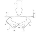
本発明の実施の形態に係る鉄筋用結束線ユニットについて図1乃至図6を用いて説明する。まず、図1は本発明に係る鉄筋用結束線ユニットの1例を示す斜視図であり、図2は同結束線ユニット1における1本の結束線の使用状況の具体例を示す説明図である。
Next, the present invention will be described in detail based on specific embodiments.
A reinforcing wire binding wire unit according to an embodiment of the present invention will be described with reference to FIGS. First, FIG. 1 is a perspective view showing an example of a binding wire unit for reinforcing bars according to the present invention, and FIG. 2 is an explanatory diagram showing a specific example of the usage status of one binding wire in the
鉄筋用結束線ユニット1は、「略茸形状」に形成した多数本(50〜100本)の結束線2を隣接状態に集合させ、該集合状態を使用時まで維持させるべく、隣接の長さ方向に沿って複数箇所に接着剤による帯状の皮膜3を形成し固結させることによって、個々の結束線2に分離可能に連結させたものである。
Reinforcing bar
この場合の結束線2は、直径が2.0〜3.5mmの焼き鈍し線を使用し、該焼き鈍し線は、その表面全体に黒皮(防錆の役割を果たす酸化皮膜)が存在しているものをそのまま使用するのであり、その焼き鈍し線を、例えば、型成形加工等により「略茸形状」に形成するのである。
In this case, the
この結束線2における「略茸形状」の形状については、図2(A)に示したように、結束の対象となる複数の鉄筋、例えば、主筋4と補助筋5との交差部または主筋同士の隣接する接続部が抱え込まれるループ部2aと、該ループ部2aの開口部2bから外側に僅かに開いて延長させ、所要の長さに形成した脚部2cとからなるものである。
As shown in FIG. 2A, the shape of the “substantially saddle shape” in the
そして、前記ループ部2aにおける開口部2bの間隔は、抱え込まれる主筋4の径よりも若干狭い間隔で形成されていることが好ましい。その理由は、例えば、結束すべき主筋4と補助筋5との交差部に対して結束線2を機械的に押し下げて挿着させた場合に、補助筋5に対しては何の抵抗もなく結束線2は通過するが、主筋4に対しては開口部2bが当接するので押し下げ作用に所定の抵抗・負荷が生ずる。この抵抗・負荷によって、結束線2の存在が機械的に検出され、その抵抗・負荷の検出をしながらさらに押し下げ作用をすることによって、結束線2の開口部2bが押し広げられ、主筋4の径を越えた時点で押し下げの抵抗・負荷がなくなると共に、結束線2が適正に挿着されたことを機械的に認識できるのである。もし、機械的な押し下げ作用において、抵抗・負荷が検出されないと、何等かの要因で結束線2が供給されていないことを検出して作業者に報知することができるのである。
And it is preferable that the space | interval of the
また、脚部2cの長さについては、図2(B)に示したように、適正な状態で結束線2が主筋4と補助筋5とをループ部2aで抱え込んだ後に、つまり、図2(A)の状態から拡がっている脚部2cが略平行になるように開脚幅を機械的に狭め、その脚部2cの端部に、例えば、機械的な捩り部材が係合して、少なくとも2回転以上、好ましくは3回転の捩りを加えると、結束線2が仮想線で示した位置から全体が締め付けられるのであり、その捩りが加えられても、さらに端部が捩れない状態で残っている程度の長さに形成されているのである。なお、脚部2cの長さについては、経験上、例えば、結束線2の直径の約15倍の長さがあれば足りる。
As for the length of the
次に、図3乃至図5を用いて鉄筋用結束線ユニットの製造方法について説明する。図3は型材を使用して結束線ユニットを成型加工する状況を示す説明図、図4は成形加工後に雌型型材から離脱させた状態の雄型型材を略示的に示す端面図、図5は雄型型材から成型加工した結束線を離脱させる時に用いる受け部材を略示的に示す端面図、図6は雄型型材から成型加工した結束線を離脱させる工程を略示的に示した説明図である。 Next, the manufacturing method of the binding wire unit for reinforcing bars will be described with reference to FIGS. FIG. 3 is an explanatory view showing a situation in which the binding wire unit is molded using a mold material, FIG. 4 is an end view schematically showing the male mold material in a state of being detached from the female mold material after the molding process, and FIG. FIG. 6 is an end view schematically showing a receiving member used when detaching the binding wire molded from the male mold material, and FIG. 6 schematically shows the process of detaching the binding wire molded from the male mold material. FIG.
まず、図3において、11は断面が茸状を呈する所要長さの雄型型材、12は雌型型材であり、該雌型型材12は雄型型材11の外形とほぼ対応する内部空間を有すると共に、中央部で縦方向に2分割され、且つ分割された各半体12a、12bが軸13a、13bにより開閉可能に支持された構成を有するものである。そして、雄型型材11と雌型型材12の長さは概ね40cm程度であり、雌型型材12の分割した半体12a、12bの下端部12c側は、交互に入り込めるように凹凸状態に形成したものであり、また、分割した半体12a、12bは常に開く方向に付勢されている。
First, in FIG. 3,
このような型材を使用して成形加工される線材14は、一般的に市販されているコイル状に巻かれている焼き鈍し線、例えば、直径が2.0〜3.5mmの焼き鈍し線を使用するものであり、該焼き鈍し線は、その表面全体に黒皮(防錆の役割を果たす酸化皮膜)が存在しているものをそのまま使用するか、必要があれば黒皮部分を除去して使用する。
The
この場合に、図示していないが、コイル状に巻かれている焼き鈍し線を順次引き出し、一般的に使用されている直線機で歪みを除去すると共に、必要があれば表面の黒皮部分を回転式ワイヤブラシで取り除いて直線状態にした後に、所要長さ、例えば23±2cm程度の範囲において、設定した直線長さの線材14に切断し、該切断した複数本の線材14を前記雌型型材12の開口部を横切る(直交)ように隣接状態に並べる。このときに、複数本の線材14が雌型型材12に対して正確に直交状態で且つ隣接状態に並べられているか否かをチェックすると共に、少なくとも位置決めと一方の端部が揃うように当て板などの整揃手段15が設けられている。
In this case, although not shown in the figure, the annealed wire wound in a coil shape is drawn out sequentially, the distortion is removed with a commonly used linear machine, and the black skin part of the surface is rotated if necessary. After removing it with a wire brush and making it straight, it is cut into a
このように複数本の線材、例えば、直径が2.0mmの線材14の場合は80〜100本、直径が3.5mmの線材14の場合は50〜70本を整揃配設した後に、雄型型材11を下降させると該雄型型材11の先端部が線材14の中央部に当接して押し下げ、それによって線材14は雄型型材11の先端部側の形状に沿って湾曲する。そして、さらに雄型型材11がそのまま押し下げられることにより、雌型型材12の下端部12c側に当接して押し下げると、該雌型型材12の半体12a、12bが軸13a、13bにより閉じる方向に回転し、その閉じる方向の回転によって線材14を雄型型材11の外形に沿わせて順次変形させ、雄型型材11が下死点に達した時に雌型型材12が完全に閉まって線材14を外側から締め付け、両型材によって線材14が雄型型材11の外形形状、即ち、前記結束線2の形状に成形される。
As described above, after arranging a plurality of wires, for example, 80 to 100 in the case of the
雄型型材11が下死点に達した後に上昇する。その上昇作用によって押圧力が開放され雌型型材12の分割した半体12a、12bは、それぞれ軸13a、13bを中心に開く方向に付勢されており、雌型型材12が開き、図4に示したように、雄型型材11は結束線2の形状、つまり、ループ部2aと脚部2cとが一連に成形された線材14を外周面に保持したまま雌型型材12から離脱し上昇する。この時に、成形された線材14は、雌型型材12による外側からの締め付けから開放されるので、自己の有する剛性と反発力とによって線材14の両端部側、即ち、脚部2cが少し開くようになり、それによって雄型型材11との間に僅かな空隙が生じるようになる。
The
上昇した雄型型材11は、少し移動させて別の位置に設定され、その位置において、雄型型材11から結束線2の形状に成型された線材14を離型させる。この場合に、図5に示したような、線材14を結束線2の形状に成形したままの状態で受け取れる受け部材16が用いられる。この受け部材16は、雄型型材11の外形とほぼ同形状で僅かに小寸法のものが使用され、先端部16aの円形状をほとんど変えないように2分割し、先端側の軸17を介して2分割の半体16b、16cが開閉できるように構成されている。なお、結束線2の形状に成型された線材14を受け取った後にガタツキがないように、例えば、楔材18等を半体16b、16cの後端側の間に打ち込んで開くようにし、結束線2の保持状態を安定させて次の工程に移送する。
The raised
このような受け部材16を、図6に示したように、前記成形された線材14を外周面に保持した雄型型材11の端部に当接させ、適宜の押し出し手段19等により線材14を受け部材16側に移動させる。この場合に、線材14は結束線2の形状に成形された状態、即ち複数本の線材14が隣接状態を維持したまま受け部材16に受け渡されるのである。なお、押し出し手段19は、例えば、雄型型材11の少なくとも左右4箇所に設けてあって、これらが端部に位置する線材14に当接し、一つの駆動源で同時に均等な押し出し力をもって押し出し動作をするのである。要するに、雄型型材11から線材14を一方の端部から他方の端部に移動させ、その他方の端部でサイズ的に一回り小さい受け部材16にそのまま押し出して移送し受け渡しができれば良いのである。
As shown in FIG. 6, such a receiving
受け部材16で受け取った結束線2の形状に成形された線材14は、受け部材16のサイズが一回り小さいので多少ガタツキのある状態になっているが、線材14における隣接状態の順序は全く変わらないのであり、その受け部材16の半体16b、16cの後端部側の間に楔材18等を打ち込みながら、線材14を両側から押して中央部に寄せることによって雄型型材11で成型した時と同じように結束線2の形状に成形された線材14を隣接状態に整然と整列させることができるのである。
The
このように整然と整列させた結束線2形状の線材14を乗せた受け部材16は、次の工程に搬送して最終製品に仕上げるまでその状態が維持されるのである。即ち、次工程においては、図1に示したように、複数箇所に接着剤による皮膜2の形成工程を行うこと、例えば、粘りの少ない接着剤を帯状に噴霧塗布して乾燥させる工程を行うのである。
The receiving
この場合に、皮膜を必要としない(塗装しない)部分は機械的に目隠しをして噴霧塗布すれば、予定した範囲に予定した強度の皮膜が形成できるのである。しかも、その皮膜は隣接状態にある線材14の山と谷とに沿って略均一に塗布でき、それによって複数本の結束線2形状の線材14がバラバラにならないように隣接状態にまとめられるのである。
In this case, if a portion that does not require a coating (not painted) is mechanically blinded and spray-coated, a coating having a predetermined strength can be formed in a predetermined range. In addition, the coating can be applied substantially uniformly along the peaks and valleys of the
接着剤の塗布工程後に結束線2形状の線材14を乗せた受け部材16は、接着剤が乾燥するまで、そのままの状態で保管し、乾燥した時点で受け部材16の楔材18を除去して結束線2形状の線材14を抜き取り適宜の包装をして製品(鉄筋用結束線ユニット)となるのである。
The receiving
いずれにしても本発明に係る鉄筋用結束線ユニットは、連接保持させた個々の鉄筋用結束線には、結束結合される複数の鉄筋が抱え込まれるループ部と、該ループ部に複数の鉄筋を抱え込ませた状態で捩り合わせることにより該鉄筋同士を結合させる脚部を一連に形成し、複数の前記鉄筋用結束線を隣接状態に且つ分離可能に皮膜材で連接保持させたものであり、断面が円形の線材で、特に、表面が黒皮で覆われ直径が2.0〜3.5mmの焼き鈍し線をそのまま使用したことにより、防錆機能を有すると共に結束強度が高いものを型成形で安価に製造できるので、例えば、主筋の径が35mmで補助筋の径が20mm程度の比較的太い鉄筋を結束するために使用できるのであり、しかも、所要の自動結束装置にセットして、1本づつを押し出したときに、交差部分または継手部分をループ部で抱えるようになり、その状態で脚部を捩り合わせることにより簡単に結束できるのであり、耐震性の鉄筋コンクリート構造物の鉄筋組立に広く利用できるのである。 In any case, the reinforcing wire binding wire unit according to the present invention includes a loop portion in which a plurality of reinforcing bars to be bound and bonded are held in each of the rebar binding wires connected and held, and a plurality of reinforcing bars in the loop portion. A series of leg portions for joining the reinforcing bars by twisting them together while holding them, and connecting and holding a plurality of the binding wires for the reinforcing bars in an adjacent state and separable with a coating material. Is a round wire, especially by using an annealed wire with a surface covered with black skin and a diameter of 2.0 to 3.5 mm as it is. For example, it can be used to bind a relatively thick reinforcing bar having a main bar diameter of 35 mm and an auxiliary bar diameter of about 20 mm, and is set in a required automatic binding device one by one. Press When this happens, the crossing part or joint part will be held by the loop part, and it can be easily bundled by twisting the legs in that state, and it can be widely used for rebar assembly of earthquake resistant reinforced concrete structures .
また、本発明の鉄筋用結束線ユニットの製造方法は、断面茸状を呈する雄型型材と、該雄型型材の外形とほぼ対応する内部空間を有すると共に、中央部で2分割され且つ分割された各半体が軸により開閉可能に支持された雌型型材とを使用し、表面が黒皮で覆われ直径が2.0〜3.5mmの焼き鈍し線をそのまま所要長さに切断して雌型型材の開口部に複数本並べ、雄型型材で押圧することによって雌型型材の内部に強制的に押し込んでループ部と脚部とを一連に成形して結束線を隣接状態で形成し、隣接状態に成形した線材を皮膜材により分離可能に接合して結束線ユニットとしたものであり、型成形によるため製造が容易であり表面に黒皮が存在して錆びない結束線を安価に提供できるのであり、各種鉄筋編組体用の結束線として広く利用できる。 In addition, the manufacturing method of the binding wire unit for reinforcing bars of the present invention has a male mold material having a cross-sectional shape and an internal space substantially corresponding to the outer shape of the male mold material, and is divided into two at the center and divided. In addition, a female mold material in which each half is supported so as to be opened and closed by a shaft is used, and an annealed wire whose surface is covered with black skin and has a diameter of 2.0 to 3.5 mm is cut into a required length as it is. A plurality of lines are arranged in the opening of the mold material, and pressed into the female mold material by pressing with the male mold material, and the loop portion and the leg portion are formed in series to form a binding line in an adjacent state, Bonded wire unit is formed by joining wire rods molded adjacent to each other so as to be separable by a coating material, and it is easy to manufacture because it is molded, and it provides a low-cost binding wire that does not rust due to the presence of black skin on the surface. Can be widely used as a binding wire for various types of reinforcing steel braids You can use.
1 鉄筋用結束線ユニット
2 結束線
2a ループ部
2b 開口部
2c 脚部
3 接着剤の皮膜
4 主筋
5 補助筋
11 雄型型材
12 雌型型材
12a、12b 半体
12c 下端部
13a、13b 軸
14 線材
15 当て板などの整揃手段
16 受け部材
16a 下端部
16b、16c 半体
17 軸
18 楔材
19 押し出し手段
DESCRIPTION OF
Claims (5)
該鉄筋用結束線には、結束結合される複数の鉄筋が抱え込まれるループ部と、該ループ部に複数の鉄筋を抱え込ませた状態で捩り合わせることにより該鉄筋同士を結合させる脚部を一連に形成し、
複数の前記鉄筋用結束線を隣接状態に且つ分離可能に皮膜材で連接保持させた構造であること
を特徴とする鉄筋用結束線ユニット。 Reinforcing bar binding wire for joining crossing or joint parts of reinforcing bars to assemble reinforcing bars arranged inside a concrete building,
The binding wire for reinforcing bars is a series of a loop portion that holds a plurality of reinforcing bars to be bound and joined together, and a leg portion that connects the reinforcing bars by twisting them together while holding the reinforcing bars in the loop portion. Forming,
A reinforcing wire binding wire unit characterized in that it has a structure in which a plurality of the reinforcing wire binding wires are connected and held in an adjacent state and separable by a coating material.
接着剤皮膜によること
を特徴とする請求項1に記載の鉄筋用結束線ユニット。 The connection holding of the reinforcing wire binding wire is
The reinforcing wire binding wire unit according to claim 1, wherein the binding wire unit is made of an adhesive film.
焼き鈍し線で形成されていること
を特徴とする請求項1または2に記載の鉄筋用結束線ユニット。 The binding wire for reinforcing bars is
Be formed of annealed wire
The binding wire unit for reinforcing bars according to claim 1 or 2.
断面茸状を呈する雄型型材と、該雄型型材の外形とほぼ対応する内部空間を有すると共に、中央部で2分割され且つ分割された各半体が軸により開閉可能に支持された雌型型材とを使用するものであり、
コイル状に巻かれている焼き鈍し線を順次引き出して直線機で歪みを除去した後に所要長さの直線線材に切断する工程と、
該切断した直線線材の複数本を前記雌型型材の開口部を横切るように隣接状態に並べて端部を揃えて配設する工程と、
該配設した直線線材の上部中央部から該線材を押し曲げながら前記雄型型材を降下させると共に、雌型型材の底部に当接してさらに下降させることにより雌型型材を閉じて線材を雄型型材の外形に沿わせてループ部と脚部とを一連に成形する工程と、
該成形工程後に、雄型型材を上昇させてループ部と脚部とを成形した線材と一緒に雌型型材から離型させると共に、上昇位置において雄型型材から成形した線材を隣接状態のまま離型させる工程と、
該離型させた隣接状態の成形した線材を皮膜材により分離可能に接合する工程とからなること
を特徴とする鉄筋用結束線ユニットの製造方法。 A method of manufacturing a rebar binding wire unit for joining crossing or joint portions of rebars to assemble rebars arranged inside a concrete building,
A male mold having a bowl-shaped cross-section, and a female mold having an internal space substantially corresponding to the outer shape of the male mold, and being divided into two at the center and each of the divided halves supported to be opened and closed by a shaft Using mold material,
A step of sequentially drawing the annealed wire wound in a coil shape and removing the distortion with a straight line machine, and then cutting the wire into a required length,
Arranging a plurality of the cut straight wire rods in an adjacent state so as to cross the opening of the female mold member, and arranging the ends aligned;
The male mold member is lowered while pushing and bending the wire rod from the upper central portion of the arranged linear wire rod, and the female mold member is closed by further lowering by contacting the bottom portion of the female mold member to make the wire rod male. A step of forming a loop portion and a leg portion in series along the outer shape of the mold material,
After the molding step, the male mold material is raised to release the female mold material together with the wire material having the loop portion and the leg portion formed, and the wire material molded from the male mold material is released in the adjacent state at the raised position. Molding, and
A step of joining the formed wire rods in the adjacent state separated from each other so as to be separable by a coating material.
The manufacturing method of the binding wire unit for reinforcing bars characterized by these.
成形した線材の隣接方向に帯状の接着剤皮膜を形成することにより複数箇所で行うこと
を特徴とする請求項4に記載の鉄筋用結束線ユニットの製造方法。 Joining with the coating material is
The method for producing a binding wire unit for reinforcing bars according to claim 4, wherein the strip-like adhesive film is formed in a plurality of locations by forming a strip-like adhesive film in the adjacent direction of the formed wire.
Priority Applications (1)
| Application Number | Priority Date | Filing Date | Title |
|---|---|---|---|
| JP2007214701A JP5179116B2 (en) | 2007-08-21 | 2007-08-21 | Reinforcing bar binding wire unit and manufacturing method thereof |
Applications Claiming Priority (1)
| Application Number | Priority Date | Filing Date | Title |
|---|---|---|---|
| JP2007214701A JP5179116B2 (en) | 2007-08-21 | 2007-08-21 | Reinforcing bar binding wire unit and manufacturing method thereof |
Publications (2)
| Publication Number | Publication Date |
|---|---|
| JP2009046902A true JP2009046902A (en) | 2009-03-05 |
| JP5179116B2 JP5179116B2 (en) | 2013-04-10 |
Family
ID=40499369
Family Applications (1)
| Application Number | Title | Priority Date | Filing Date |
|---|---|---|---|
| JP2007214701A Expired - Fee Related JP5179116B2 (en) | 2007-08-21 | 2007-08-21 | Reinforcing bar binding wire unit and manufacturing method thereof |
Country Status (1)
| Country | Link |
|---|---|
| JP (1) | JP5179116B2 (en) |
Cited By (1)
| Publication number | Priority date | Publication date | Assignee | Title |
|---|---|---|---|---|
| CN113550495A (en) * | 2020-04-24 | 2021-10-26 | 朴性昱 | Device for preventing stirrup from loosening |
Citations (8)
| Publication number | Priority date | Publication date | Assignee | Title |
|---|---|---|---|---|
| JPS5245132A (en) * | 1975-10-07 | 1977-04-09 | Osaka Transformer Co Ltd | Reinforcement tying apparatus |
| JPH02101261A (en) * | 1988-10-05 | 1990-04-13 | Kazuo Tejima | Reinforcing bar binder |
| JPH0821099A (en) * | 1994-07-08 | 1996-01-23 | Hamada Tekkin Koki Kk | Reinforcement binding method, and binding wire therefor |
| JPH10169097A (en) * | 1996-12-05 | 1998-06-23 | Hitachi Nizukuri Kk | Reinforcement intersection binder |
| JP2000336844A (en) * | 1999-05-28 | 2000-12-05 | Taisei Corp | Binding wire for reinforcement work |
| JP2003090313A (en) * | 2001-09-20 | 2003-03-28 | Sugimura Kagaku Kogyo Kk | Staple joining body |
| JP2005139622A (en) * | 2003-11-04 | 2005-06-02 | Takahashi Seisakusho:Kk | Reinforcement binding fitting |
| JP2008297710A (en) * | 2007-05-29 | 2008-12-11 | Sapuron Kenzai Kogyo Kk | Method and apparatus for automatically binding reinforcements together |
-
2007
- 2007-08-21 JP JP2007214701A patent/JP5179116B2/en not_active Expired - Fee Related
Patent Citations (8)
| Publication number | Priority date | Publication date | Assignee | Title |
|---|---|---|---|---|
| JPS5245132A (en) * | 1975-10-07 | 1977-04-09 | Osaka Transformer Co Ltd | Reinforcement tying apparatus |
| JPH02101261A (en) * | 1988-10-05 | 1990-04-13 | Kazuo Tejima | Reinforcing bar binder |
| JPH0821099A (en) * | 1994-07-08 | 1996-01-23 | Hamada Tekkin Koki Kk | Reinforcement binding method, and binding wire therefor |
| JPH10169097A (en) * | 1996-12-05 | 1998-06-23 | Hitachi Nizukuri Kk | Reinforcement intersection binder |
| JP2000336844A (en) * | 1999-05-28 | 2000-12-05 | Taisei Corp | Binding wire for reinforcement work |
| JP2003090313A (en) * | 2001-09-20 | 2003-03-28 | Sugimura Kagaku Kogyo Kk | Staple joining body |
| JP2005139622A (en) * | 2003-11-04 | 2005-06-02 | Takahashi Seisakusho:Kk | Reinforcement binding fitting |
| JP2008297710A (en) * | 2007-05-29 | 2008-12-11 | Sapuron Kenzai Kogyo Kk | Method and apparatus for automatically binding reinforcements together |
Cited By (1)
| Publication number | Priority date | Publication date | Assignee | Title |
|---|---|---|---|---|
| CN113550495A (en) * | 2020-04-24 | 2021-10-26 | 朴性昱 | Device for preventing stirrup from loosening |
Also Published As
| Publication number | Publication date |
|---|---|
| JP5179116B2 (en) | 2013-04-10 |
Similar Documents
| Publication | Publication Date | Title |
|---|---|---|
| TWI710503B (en) | Bundling machine | |
| JP5674762B2 (en) | Strengthening bar binding machine | |
| JP6202406B2 (en) | Method for producing reinforced steel bars for reinforced concrete | |
| EP1856346A1 (en) | A method, an apparatus and a means for making a reinforcement mesh | |
| JP5715503B2 (en) | Reinforcing bar clip, closed type reinforcing bar using the same, and manufacturing method of the closed type reinforcing bar | |
| KR101614414B1 (en) | Apartment Masonry Wall Reinforcement Device | |
| JP5179116B2 (en) | Reinforcing bar binding wire unit and manufacturing method thereof | |
| JP5973206B2 (en) | Wall construction method | |
| JP5189468B2 (en) | Rebar binding device | |
| JP4785897B2 (en) | Unit rebar manufacturing equipment | |
| JP2009180010A (en) | Method and device for binding reinforcement | |
| JP4961265B2 (en) | Method and apparatus for automatically binding reinforcing bars | |
| JP3206500U (en) | Reinforcing bar standard equipment | |
| JP5144435B2 (en) | Rebar binding device | |
| JP5985799B2 (en) | Reinforcement structure with joint metal parts and openings | |
| JP4623519B2 (en) | Structure of spiral hoop for piles and construction method of RC piles | |
| JP4388950B2 (en) | Manufacturing method of articulated rebar binding wire and rebar binding wire obtained by the method | |
| KR20110011239U (en) | Tie | |
| JP6324105B2 (en) | Concrete splicing method | |
| JP5144377B2 (en) | Reinforcing bar binding device and binding wire | |
| JP2009270413A (en) | Reinforcement binding wire material and electric binding machine thereof | |
| KR20100124432A (en) | Cable tie | |
| KR100541609B1 (en) | Structure for debonding of prestressed concrete beam member with prestressing tendon and manufacturing method of prestressed concrete beam member thereby | |
| JP3904907B2 (en) | Assembled rebar rod and its assembly method | |
| JP2013133701A (en) | Binding wire for reinforcement work |
Legal Events
| Date | Code | Title | Description |
|---|---|---|---|
| A621 | Written request for application examination |
Free format text: JAPANESE INTERMEDIATE CODE: A621 Effective date: 20100817 |
|
| A131 | Notification of reasons for refusal |
Free format text: JAPANESE INTERMEDIATE CODE: A131 Effective date: 20120828 |
|
| A521 | Request for written amendment filed |
Free format text: JAPANESE INTERMEDIATE CODE: A523 Effective date: 20121019 |
|
| TRDD | Decision of grant or rejection written | ||
| A01 | Written decision to grant a patent or to grant a registration (utility model) |
Free format text: JAPANESE INTERMEDIATE CODE: A01 Effective date: 20121211 |
|
| A61 | First payment of annual fees (during grant procedure) |
Free format text: JAPANESE INTERMEDIATE CODE: A61 Effective date: 20130109 |
|
| R150 | Certificate of patent or registration of utility model |
Ref document number: 5179116 Country of ref document: JP Free format text: JAPANESE INTERMEDIATE CODE: R150 |
|
| R250 | Receipt of annual fees |
Free format text: JAPANESE INTERMEDIATE CODE: R250 |
|
| R250 | Receipt of annual fees |
Free format text: JAPANESE INTERMEDIATE CODE: R250 |
|
| R250 | Receipt of annual fees |
Free format text: JAPANESE INTERMEDIATE CODE: R250 |
|
| R250 | Receipt of annual fees |
Free format text: JAPANESE INTERMEDIATE CODE: R250 |
|
| R250 | Receipt of annual fees |
Free format text: JAPANESE INTERMEDIATE CODE: R250 |
|
| R250 | Receipt of annual fees |
Free format text: JAPANESE INTERMEDIATE CODE: R250 |
|
| LAPS | Cancellation because of no payment of annual fees |