JP2009046876A - Drawing device for existing pile - Google Patents
Drawing device for existing pile Download PDFInfo
- Publication number
- JP2009046876A JP2009046876A JP2007213797A JP2007213797A JP2009046876A JP 2009046876 A JP2009046876 A JP 2009046876A JP 2007213797 A JP2007213797 A JP 2007213797A JP 2007213797 A JP2007213797 A JP 2007213797A JP 2009046876 A JP2009046876 A JP 2009046876A
- Authority
- JP
- Japan
- Prior art keywords
- casing
- existing pile
- claw
- gripping
- gripping claw
- Prior art date
- Legal status (The legal status is an assumption and is not a legal conclusion. Google has not performed a legal analysis and makes no representation as to the accuracy of the status listed.)
- Pending
Links
Images


Landscapes
- Placing Or Removing Of Piles Or Sheet Piles, Or Accessories Thereof (AREA)
Abstract
Description
この発明は、建築構造物の建て替えなどのときに、地中に埋設されている既設杭を撤去するために使用される既設杭の引抜装置に関する。 The present invention relates to an existing pile pulling device used for removing an existing pile buried in the ground when rebuilding a building structure or the like.
例えば、ビルやマンション,工場などの建築構造物は、その荷重を支持するために地中の固い地盤まで杭が埋め込まれている。これらの建築構造物の建て替えを行う場合は、古い建物を解体撤去した後、地中に深く埋め込まれた古い既設杭を引き抜く作業を行う必要がある。従来においては、地中に埋設された不要な杭を撤去する方法として、車両のリーダに沿って昇降するオーガマシンにより回転駆動される回転ケーシングによって、地中の既設杭の周囲を掘削しながら既設杭の上端部近くまで掘進した後、この杭の上端部の周面にワイヤーを縛り付けてクレーンで引き上げることにより、既設杭を地中から引き抜いていた。 For example, in a building structure such as a building, a condominium, and a factory, piles are embedded up to a hard ground in the ground to support the load. When rebuilding these building structures, after dismantling and removing the old building, it is necessary to pull out the old existing piles deeply buried in the ground. Conventionally, as a method of removing unnecessary piles buried in the ground, an existing installation is performed while excavating around the existing piles in the ground by a rotating casing that is rotated by an auger machine that moves up and down along the leader of the vehicle. After excavating near the upper end of the pile, the existing pile was pulled out from the ground by binding a wire to the peripheral surface of the upper end of the pile and pulling it up with a crane.
しかし、上記のような方法では、ケーシングによる掘削後に、ケーシングを引き上げ、さらに既設杭の上端部にワイヤーを外れないように縛り付ける必要があるため、作業に多大な手間と時間がかかる。その上、既設杭の上端部にワイヤーを縛って引き上げるため、引き上げの際に杭が途中で切断されてしまうこともあり、その切断されて地中に残った杭の引き抜き作業は容易ではなく、その作業は困難を極める。 However, in the method as described above, it is necessary to pull up the casing after excavation by the casing and bind the wire to the upper end of the existing pile so as not to come off, so that the work takes a lot of labor and time. In addition, since the wire is tied to the upper end of the existing pile and pulled up, the pile may be cut off halfway during the pulling up, and it is not easy to pull out the pile that has been cut and left in the ground, The task is extremely difficult.
そこで、近年、上記の従来の方法と同様に、ケーシングで地中の既設杭の周囲を掘削して既設杭と地盤との縁を切った後に、ケーシングの下部に設けられた複数の把持爪をケーシングの内部に突出させて既設杭の下端部を把持し、ウインチによるオーガマシンの上昇移動によってケーシングとともに既設杭を地中から引き抜くようにした既設杭の引抜装置が提案されている。この種の既設杭の引抜装置では、把持爪をケーシング内部に対して出没動作させるために油圧シリンダが用いられたものが提案されている(例えば、特許文献1参照。)。 Therefore, in recent years, similar to the conventional method described above, after excavating the periphery of an existing pile in the ground with a casing and cutting the edge between the existing pile and the ground, a plurality of gripping claws provided at the lower portion of the casing are removed. An existing pile pulling device has been proposed in which a lower end portion of an existing pile is gripped by projecting into the casing, and the existing pile is pulled out from the ground together with the casing by the upward movement of the auger machine by the winch. In this type of existing pile pulling device, there has been proposed one in which a hydraulic cylinder is used to cause the gripping claws to move in and out of the casing (see, for example, Patent Document 1).
特許文献1に記載の既設杭の引抜装置は、油圧シリンダをケーシングの上端部に取り付け、油圧シリンダのピストンロッドに連結ロッドを介して把持爪が接続されている。把持爪はケーシングの下部に起伏動作可能に設けられており、油圧シリンダのピストンロッドを伸長させて連結ロッドを下方に移動させると、把持爪は倒伏動作してその先端部がケーシングの内部に突出し、既設杭の下端を把持する把持状態へと移行する。一方、油圧シリンダのピストンロッドを収縮させて連結ロッドを上方に移動させると、把持爪は起立動作してその先端部がケーシングの内部より退避し、上記把持状態から既設杭の下端を把持しない非把持状態へと移行する。
In an existing pile pulling device described in
しかしながら、上記した構成の既設杭の引抜装置では、複数の把持爪をケーシングの内部に出没動作させるために、駆動装置として複数の油圧シリンダをケーシングの上部周囲に取り付ける必要があるため、装置全体が高価になるとともに大掛かりになるという問題がある。とりわけ、装置全体が大掛かりになると、装置の重量増加を招き、ケーシングによる掘削速度が落ちるとともに、装置の移動性も悪くなるので、既設杭の引き抜き作業の効率が下がることになる。さらに、ケーシングを地中に押し込む際には、油圧シリンダや連結ロッドもケーシングとともに地中に押し込まれるため、土砂の抵抗を受けることにより、装置を構成する油圧シリンダや連結ロッドが損傷しやすいという問題もある。 However, in the existing pile pulling device having the above-described configuration, in order to move the plurality of gripping claws into and out of the casing, it is necessary to attach a plurality of hydraulic cylinders around the upper portion of the casing as a driving device. There is a problem that it becomes expensive and large. In particular, when the entire apparatus becomes large, the weight of the apparatus is increased, the excavation speed by the casing is lowered, and the mobility of the apparatus is also deteriorated, so that the efficiency of pulling out the existing pile is lowered. Furthermore, when the casing is pushed into the ground, the hydraulic cylinder and the connecting rod are also pushed into the ground together with the casing, so that the hydraulic cylinder and the connecting rod constituting the device are easily damaged due to the resistance of earth and sand. There is also.
この発明は、上記した問題に着目してなされたもので、把持爪をケーシング内部に対して出没動作させるための構成に油圧シリンダなどの駆動装置を必要とせずに、その構成の簡素化およびコンパクト化を実現した既設杭の引抜装置を提供することを目的とする。 The present invention has been made paying attention to the above-described problems, and does not require a driving device such as a hydraulic cylinder in the configuration for moving the gripping claw in and out of the casing. An object of the present invention is to provide an existing pile pulling device that realizes the structure.
この発明による既設杭の引抜装置は、地中に埋設された既設杭の周囲を掘るための掘削刃を下端に有し前記既設杭を囲むように地中に押し込まれる筒状のケーシングと、前記ケーシングをその中心軸の回りに正逆方向へ回転駆動させることが可能な回転駆動装置と、前記ケーシングの下部にケーシング内に突き出て既設杭の下端に係合するようにケーシング内に対して出没可能に設けられる少なくとも1個の把持爪とを備えたものである。前記ケーシングは、前記把持爪が設けられる位置に内外に把持爪を突出させる窓孔部を有している。前記把持爪は、水平面内で回動自由となるよう長さ方向の中間部分がケーシングに軸支されるとともに、その軸支部より先の部分がケーシング内に突出して既設杭の下端に係合することが可能な角度位置と既設杭の下端に係合しない角度位置との間を往復動しかつ前記軸支部より後の部分がケーシングの外周面より突出した状態のままとなるように軸支部より先後の部分の長さと回動角度範囲とが設定されている。 A pulling device for an existing pile according to the present invention has a cylindrical casing that is pushed into the ground so as to surround the existing pile with a drilling blade for digging around the existing pile buried in the ground, A rotary drive device capable of rotating the casing around its central axis in forward and reverse directions, and a projecting part that protrudes into the casing at the lower part of the casing and engages with the lower end of the existing pile. It is provided with at least one gripping claw that can be provided. The casing has a window hole portion for projecting the gripping claws in and out at a position where the gripping claws are provided. The gripping claws are pivotally supported by the casing in the longitudinal direction so that they can freely rotate in a horizontal plane, and a portion ahead of the pivotal support projects into the casing and engages the lower end of the existing pile. Reciprocating between the angular position where it can be engaged and the angular position where it does not engage with the lower end of the existing pile, and the portion behind the shaft support portion remains protruding from the outer peripheral surface of the casing. The lengths of the front and rear portions and the rotation angle range are set.
この発明による既設杭の引抜装置は、回転駆動装置によりケーシングを回転させながら既設杭の周囲を掘削刃により堀削する。ケーシングを地中においてその中心軸の回りに正または逆方向へ回転させると、前記把持爪のケーシングの外周面から突き出た部分が土砂の抵抗を受けることによって把持爪が軸支部を支点として水平面内で正または逆方向に回動する。把持爪の軸支部より先の部分は、ケーシング内に突き出て既設杭の下端に係合することが可能な角度位置(以下、「係合位置」という。)と既設杭の下端に係合しない角度位置(以下、「退避位置」という。)との間に亘って回動する。 The existing pile pulling apparatus according to the present invention excavates the periphery of the existing pile with the excavating blade while rotating the casing by the rotation driving device. When the casing is rotated in the forward or reverse direction around its central axis in the ground, the gripping claws project from the outer peripheral surface of the casing to receive the resistance of earth and sand, so that the gripping claws are supported in the horizontal plane with the pivotal support as a fulcrum. To rotate in the forward or reverse direction. The portion of the gripping claw that is beyond the pivotal support portion protrudes into the casing and engages with the lower end of the existing pile and is not engaged with the lower end of the existing pile. It rotates between an angular position (hereinafter referred to as “retracted position”).
上記した構成の既設杭の引抜装置により地中に埋設されている既設杭を引き抜くためには、前記把持爪の軸支部より先の部分が前記退避位置に定位するように所定の方向へケーシングを回転させながら地中に押し込む。ケーシングの下端が既設杭の下端よりも少し下方まで達したところで、ケーシングを押し込み時とは逆方向に回転させると、把持爪が逆方向に回動してその軸支部より先の部分が前記係合位置へ移行する。この状態で、ケーシングを引き上げると、把持爪の軸支部より先の部分が既設杭の下端に係合し、既設杭は把持爪によって把持される。この既設杭を把持した状態でケーシングを引き続き引き上げることで、既設杭をケーシング内に収容した状態で地中から引き抜くことができる。 In order to pull out the existing pile buried in the ground by the existing pile pulling device having the above-described configuration, the casing is moved in a predetermined direction so that the portion ahead of the shaft support portion of the gripping claw is localized at the retracted position. Push into the ground while rotating. When the lower end of the casing reaches a little lower than the lower end of the existing pile, when the casing is rotated in the direction opposite to that when the casing is pushed in, the gripping claw rotates in the opposite direction and the portion beyond the shaft support part is Move to the matching position. In this state, when the casing is pulled up, the portion of the gripping claw that is ahead of the shaft support portion engages with the lower end of the existing pile, and the existing pile is gripped by the gripping claw. By continuously pulling up the casing while holding the existing pile, the existing pile can be pulled out from the ground while being accommodated in the casing.
上記した構成の既設杭の引抜装置によると、ケーシングを地中で正逆方向に回転させることにより把持爪が正逆方向に回動して、その軸支部より先の部分がケーシング内に対して出没動作を行うので、把持爪をケーシング内に対して出没動作させるための油圧シリンダなどの駆動装置をケーシングに設ける必要がなく、装置全体の構成を簡素化およびコンパクト化することができるとともに、ケーシングの押し込みに際して従来の既設杭の引抜装置のように装置の損傷が発生することもない。 According to the existing pile pulling device having the above-described configuration, the gripping claw rotates in the forward / reverse direction by rotating the casing in the forward / reverse direction in the ground, and the portion beyond the axial support portion is in the casing. Since the projecting operation is performed, it is not necessary to provide the casing with a drive device such as a hydraulic cylinder for causing the gripping claw to move in and out of the casing, and the configuration of the entire apparatus can be simplified and made compact. The apparatus is not damaged like the conventional existing pulling apparatus for pushing in.
この発明の好ましい実施態様においては、前記ケーシングの内面には、前記把持爪の軸支部より先の部分が既設杭の下端に係合しない角度位置にあるときに当該把持爪の軸支部より先の部分が嵌合することが可能な爪収容部が凹設されている。
この実施態様によると、把持爪の軸支部より先の部分は既設杭の下端に係合しない前記退避位置にあるときには、ケーシング内面の爪収容部に収容されるので、ケーシング内に把持爪の軸支部より先の部分が突き出るようなことはなく、ケーシングの地中への押し込み時に把持爪が既設杭に接触するなどの支障を生じるおそれはない。
In a preferred embodiment of the present invention, on the inner surface of the casing, when the portion ahead of the shaft support portion of the grip claw is at an angular position where it does not engage with the lower end of the existing pile, the shaft support portion ahead of the grip claw shaft portion is provided. A claw receiving portion into which the portions can be fitted is recessed.
According to this embodiment, when the portion of the gripping claw beyond the shaft support portion is in the retracted position where it does not engage with the lower end of the existing pile, the portion of the gripping claw is accommodated in the casing. There is no possibility that the part ahead of the branch protrudes, and there is no possibility that the gripping claws may come into contact with the existing pile when the casing is pushed into the ground.
この発明の好ましい実施態様においては、前記把持爪は、窓孔部内で上下方向へ変位することが可能なように軸支されており、把持爪の下面と窓孔部の開口下縁の間には、把持爪の軸支部より先の部分がケーシング内に突き出て既設杭の下端に係合することが可能な角度位置にあるときに互いに噛み合って把持爪の回動を規制することが可能な回り止め機構が設けられている。 In a preferred embodiment of the present invention, the gripping claw is pivotally supported so as to be able to be displaced in the vertical direction within the window hole, and between the lower surface of the gripping claw and the lower opening edge of the window hole. Is capable of restricting the rotation of the gripping claws by engaging with each other when the portion ahead of the shaft support portion of the gripping claws protrudes into the casing and is in an angular position where it can be engaged with the lower end of the existing pile. A detent mechanism is provided.
この実施態様によると、把持爪の軸支部より先の部分が既設杭の下端に係合することが可能な前記係合位置に位置するときには、回り止め機構の作用により把持爪の水平方向への回動が完全に規制されるので、前記把持爪の軸支部より先の部分がその係合位置から係合が外れる方向に変位することはない。 According to this embodiment, when the portion ahead of the shaft support portion of the gripping claw is located at the engagement position at which the lower end of the existing pile can be engaged, the gripping claw is moved horizontally by the action of the detent mechanism. Since the rotation is completely restricted, the portion of the grip claw beyond the shaft support portion is not displaced in the direction in which the engagement is disengaged from the engagement position.
この発明によると、ケーシングを地中で正逆方向に回転させることにより把持爪が回動し、その軸支部より先の部分がケーシング内に対して出没動作可能となるので、従来例の既設杭の引抜装置のように、把持爪をケーシング内に対して出没動作させるために、油圧シリンダなどの駆動装置を設ける必要がなく、装置全体の構成の簡素化およびコンパクト化を実現できる。 According to the present invention, the gripping claws are rotated by rotating the casing in the forward and reverse directions in the ground, and the portion ahead of the shaft support portion can be moved into and out of the casing. In order to cause the gripping claw to move in and out of the casing as in the pulling device, it is not necessary to provide a driving device such as a hydraulic cylinder, and the configuration of the entire device can be simplified and made compact.
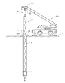
図1および図2は、この発明の一実施例である既設杭の引抜装置1(以下、「杭引抜装置」という。)の全体構成を示している。
この発明の杭引抜装置1は、建築構造物の建て替えなどのときに、地中に埋設されている既設杭を撤去するために使用されるものであり、地中に埋設された既設杭の周囲を掘削して既設杭と地盤との縁を切るためのケーシング2と、ケーシング2を回転駆動するためのケーシング回転駆動装置3と、ケーシング2の下部に設けられケーシング2内に突き出て既設杭の下端を把持するための2個の把持爪4とを備えている。
1 and 2 show the overall configuration of an existing pile drawing device 1 (hereinafter referred to as “pile drawing device”) according to an embodiment of the present invention.
The
ケーシング回転駆動装置3は、その内部にケーシング2を回転させるための回転力を発生させるモータ(図示せず)を有し、下部には、前記モータによって回転する環状の回転駆動軸30が突出している。この回転駆動軸30の下部に連結部31が一体に設けられ、連結部31にケーシング2の上端部が一体回転可能に連結されている。
なお、図1において、10は杭引抜装置1を鉛直方向に吊り下げるクレーン車であり、ケーシング回転駆動装置3の上部に取り付けられたフック32とクレーン車10に取り付けられたフック11とを係合させて杭引抜装置1を垂直姿勢で吊り下げ、鉛直方向に昇降させる。また、12はケーシング2が地面を掘削中に歳差運動するのを防止するための振れ止め板である。
The casing
In FIG. 1,
前記ケーシング2は、既設杭の外径よりも大きい内径をもつ下端が開口した中空の円筒体から成り、例えば鋼管により形成される。ケーシング2の上面には、ケーシング回転駆動装置3の連結部31と連結可能なジョイント部20が設けられ、このジョイント部20を介して回転駆動軸30の回転とクレーン10の起伏による上下動をケーシング2へ伝達可能となっている。
The
ケーシング2の周面には、所定の大きさの開口21がケーシング2の全長にわたって複数個形成されている。この開口21を通してケーシング2の内部に挿入された既設杭の状態を目視することができるようになっている。また、この開口21は、土砂や水などをケーシング2の外部に排出させるためのものでもある。さらに、この開口21を設けることにより、ケーシング2の軽量化を図ることもできる。
A plurality of
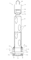
ケーシング2の下端部には、ケーシング2と内径が一致しかつケーシング2より外径および肉厚が大きい円筒体から成るヘッド部5が溶接により一体に設けられている。このヘッド部5の下端部の外周面には、図2および図3に示すように、既設杭Pの周囲の地面を削って掘り下げるための18個の掘削刃6がヘッド部5の下端部から突出するように等角度で取り付けられている。掘削刃6は、超硬合金チップやダイヤモンドなどの刃体を有し、ヘッド部5の下端部に溶接またはボルトの締付けなどによって強固に固着されている。なお、掘削刃6は、使用条件に応じてその数や取付位置を適宜最適なものに変更してもよい。
At the lower end of the
ヘッド部5には、図2および図5に示すように、ヘッド部5の周壁の一部を切り取って形成された爪収容空間7が対角位置に2箇所設けられている。各爪収容空間7は、後述する把持爪4の軸支部4Cより先の部分(以下、「先端部」という。)4Aの厚みおよび長さに適合する深さおよび周長さを有する凹状の爪収容部70と、爪収容部70に連続したヘッド部5の周壁を内外に貫通する窓孔部71とから成る。爪収容空間7の上下方向の高さは、把持爪4が上下方向に昇降できるように把持爪4の上下方向の高さwより十分に大きな値(この実施例では、把持爪4の高さwのほぼ2倍に相当する高さ)に設定してある。各爪収容空間7内にはそれぞれ把持爪4が、その先端部4Aがケーシング2の内部に突き出て既設杭Pの下端の外周面に係合することが可能な角度位置(以下、「係合位置」という。図5参照)と、ケーシング2の内部より爪収容部70内に退避して既設杭Pの下端に係合しない角度位置(以下、「退避位置」という。図4参照)との間の回動角度範囲θに亘って往復動作できるように、回動自由に支持されている。
As shown in FIGS. 2 and 5, the
なお、前記ヘッド部5は、必ずしもケーシング2に一体に形成する必要はなく、ケーシング2の下端部に着脱可能に取り付けられるように構成してもよい。このような構成にすると、地中へのケーシング2の押し込みや既設杭Pの引き抜き作業により、掘削刃6や把持爪4が破損、損傷するなどしてヘッド部5が消耗した場合には、他のヘッド部5に簡単に取り替えることが可能になる。
The
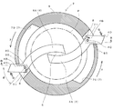
前記の各把持爪4は、例えば鋼材により形成され、図2および図5に示すように、先端部4Aがやや湾曲した形状のものである。把持爪4が回動してその先端部4Aがケーシング2の内部に最も突出するとき、先端部4Aの先端縁はケーシング2(ヘッド部5)の中心を越えた位置に達し、各把持爪4の先端部4Aでケーシング2(ヘッド部5)の中心部を囲む小スペースEを形成して既設杭Pの下端を受け止める。各把持爪4は、長さ方向の中間部分が窓孔部71内で支持軸8によって軸支されている(以下、前記中間部分を「軸支部4C」という。)。支持軸8は窓孔部71内に縦設され、両端部が窓孔部71の開口上縁および下縁に設けられた貫通孔72、嵌合孔73にそれぞれ軸止されている。各把持爪4は、支持軸8(軸支部4C)を支点として水平面内で回動自由であり、その先端部4Aがケーシング2の内部に対して出没動作可能となっている。また、各把持爪4は、支持軸8に摺動自由に支持され、窓孔部71内を支持軸8に沿って上下方向に変位することが可能となっている。
Each of the
各把持爪4は、その軸支部4Cより後の部分(以下、「後端部4B」という。)が窓孔部71を通じてヘッド部5の外周面より突き出るような長さに形成されている。把持爪4の回動角度範囲θにわたって、前記後端部4Bは一部分(以下、「突出部」という。)4Dがヘッド部5外へ突き出た状態に維持されるもので、この構造により、ケーシング2を地中で正逆方向に回転させるだけで把持爪4が回動動作し、その先端部4Aがケーシング2の内部に対して出没可能となっている。
Each
図4および図5によって具体的に説明すると、ケーシング2を図4に示すx方向に回転させながら地中に押し込むと、把持爪4の後端部4Bのケーシング2外に突き出た前記突出部4Dが土砂の抵抗を受けることによって、把持爪4には強い押圧力Nが働く。これにより、把持爪4は支持軸8を中心として図4に示すr方向に回動し、その先端部4Aがケーシング2の内部より退避して前記退避位置まで移行し、爪収納部70に嵌合する。
このようにケーシング2を回転させながら地中に押し込むときには、図6に示すように、把持爪4は前記突出部4Dに下方から土砂の抵抗Tを受けるために支持軸8に沿って窓孔部71内を上方に変位し、窓孔部71内で浮き上がったような状態で保持されることになる。
4 and 5, when the
When the
一方、把持爪4の先端部4Aが上記した退避位置にあるときに、ケーシング2を図5に示すy方向に回転させると、ケーシング2の外部に突き出た突出部4Dが土砂の抵抗を受けることによって、上記とは逆方向の強い押圧力Qが把持爪4に働く。これにより、把持爪4は支持軸8を中心として図5に示すs方向に回動し、その先端部4Aが爪収納部70からケーシング2の部に突き出て既設杭Pの下端の外周面に係合する係合位置まで移行する。この実施例では、把持爪4が回動してその先端部4Aが前記係合位置に移行ときに、把持爪4の後端部4Bが窓孔部71の開口側縁に突き当たることによりその移行を強制的に停止させて位置決めされるようになっている。
On the other hand, when the
なお、この実施例では、各把持爪4の先端部4Aは、平面形状が既設杭Pの下端の外周面の凸面に対応するようにやや湾曲した形状に形成されているが、埋設されている既設杭Pの形状に応じて種々の形状、例えば、矩形状に形成することも可能である。
In addition, in this Example, although the front-end |
また、この実施例では、各把持爪4は、その長さ方向の中間部分が窓孔部71内で支持軸8によって軸支されているが、これに限られるものではない。例えば、支持軸8をケーシング2の外周面に溶接などによって縦設し、各把持爪4が、その長さ方向の中間部分がケーシング2外で支持軸8によって軸支されるように構成してもよい。
Further, in this embodiment, each
この実施例の杭引抜装置1では、上記した構成に加えて、前記把持爪4と窓孔部71の開口下縁との間に、把持爪4の先端部4Aが既設杭Pの下端に係合する係合位置(図5参照)にあるときに、把持爪4の回動を規制することが可能な回り止め機構9が設けられている。
In the
この実施例の回り止め機構9は、図4〜図9に示すように、前記窓孔部71の開口下縁に設けられた複数の突起体90と、前記把持爪4の下面に設けられた複数の係合溝91とから成る。前記の各突起体90は、所定の長さを有するものであり、窓孔部71の開口下縁に等間隔に凸設されている。これらの突起体90は、把持爪4が既設杭Pの下端に係合する係合位置(図5および図7参照)に位置しているときに各係合溝91と対向するように、その設置位置が定められている。
As shown in FIGS. 4 to 9, the anti-rotation mechanism 9 of this embodiment is provided on a plurality of
前記の各係合溝91は、把持爪4の下面に前記突起体90の外形に適合する形状および大きさに形成されており、その配列間隔は、突起体90の配列間隔に合わせてある。なお、各突起体90や各係合溝91は、上記した形状に限らず、例えば各突起体90を半球状に、各係合溝91を円形の窪み状に、それぞれ形成してもよい。
Each of the engaging
上記構成の回り止め機構9によれば、把持爪4が既設杭Pの下端に係合する係合位置に位置しているときに、前記の各係合溝91と各突起体90とが噛み合うと、把持爪4の水平方向への回動が完全に規制される。従って、把持爪4の先端部4Aが一旦、前記係合位置に位置すると、把持爪4の回動によって既設杭Pとの係合が外れることがない。
According to the anti-rotation mechanism 9 having the above-described configuration, when the
なお、図示していないが、この杭引抜装置1には、ケーシング2の内部に水や空気を噴出させるための噴出管が上下方向に複数本配管されており、これらの噴出管の先端はケーシング2の下端部に臨ませてある。
In addition, although not shown in figure, in this pile drawing-out
次に、上記した構成の杭引抜装置1による既設杭Pの引き抜き作業を詳細に説明する。
まず、撤去する既設杭Pの上端部を地表にわずかに露出させ、図1に示す振れ止め板12を、その開口部12aが既設杭Pの周囲に位置するように設置して地表に強固に固定する。次に、クレーン車10で杭引抜装置1を吊り下げて、杭引抜装置1のケーシング2が振れ止め板12の開口部12a内に入り、かつ、ケーシング2内に既設杭Pの上端が入るように杭引抜装置1を位置決めする。
Next, the extraction operation | work of the existing pile P by the
First, the upper end portion of the existing pile P to be removed is slightly exposed on the ground surface, and the
次に、ケーシング回転駆動装置3によってケーシング2を図4に示すx方向に回転させて、ヘッド部5の下端部に固定された掘削刃6により既設杭Pの周辺の土壌を掘削しながらケーシング2を徐々に下降させて地中に押し込む。このとき、各把持爪4の先端部Aは、突出部4Bが土砂の抵抗を受けることによりケーシング2の内部より退避して爪収容部70に嵌合している。また、各把持爪4は突出部4Dを介して下方から土砂の抵抗を受けて支持軸8に沿って上方に変位している。その後、ケーシング2の下端(ヘッド部5)が既設杭Pの下端より少し下方まで達したところで(図6)、ケーシング2の回転を停止させる。
Next, the
なお、ケーシング2の地中への押し込みの際には、前記噴出管によりケーシング2の下端から水を噴出させてケーシング2の下端周辺の土砂を泥土化することにより、掘削作業の効率を向上させることができる。掘削された水を含んだ土砂はケーシング2の開口21から排出されて内部に溜まらないようになっている。
In addition, when pushing the
次に、ケーシング2を押し込み時とは逆方向(図5に示すy方向)に回転させることにより、各把持爪4を回動させてその先端部4Aを爪収容部70から一斉にケーシング2内に突出させる(図7)。この状態で、クレーン車により杭引抜装置1を引き上げると、把持爪4の先端部4Aが既設杭Pの下端部の外周面に食い込んで係合し、既設杭Pの下端部が把持爪4によって把持される(図9)。この杭引抜装置1の引き上げの際には、把持爪4は突出部4Dを介して上方から土砂の抵抗Uを受けるために支持軸8に沿って下方に変位し、把持爪4の下面の各係合溝91に各突起体90が係合するため(図8参照)、把持爪4の水平面内の回動が完全に規制される。なお、把持爪4の先端部4Aにより既設杭Pの下端部を把持した後は、把持爪4は既設杭Pの重量により下方へ押圧されるため(図9参照)、把持爪4の下面の各係合溝91と各突起体90との係合が外れることはない。
Next, by rotating the
次に、ケーシング2の回転を停止させ、既設杭Pを把持爪4によって把持した状態で引き続きクレーン車により杭引抜装置1を引き上げることで、既設杭Pをケーシング2内に収容した状態で地中から引き抜くことができる。
Next, the rotation of the
この杭引抜装置1によると、ケーシング2を地中で正逆方向に回転させることにより各把持爪4が水平面内で回動し、把持爪4の先端部4Aがケーシング2の内部に対して出没動作するので、把持爪4をケーシング2の内部に出没動作させるために油圧シリンダなどの駆動装置をケーシング2に設ける必要がない。このようにして、装置全体の構成の簡素化およびコンパクト化が実現できるため、杭引抜装置1全体の重量を軽量化でき、既設杭Pの引き抜き作業の効率が向上するとともに、低コスト化を図ることができる。
According to this
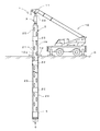
なお、上記した実施例では、前記ケーシング2は所定の長さを有する1本の鋼管により構成されているが、図10に示すように、複数のパイプを連結部22を介して縦一列に連結して1本の鋼管を構成してもよい。
図示例のケーシング2は、ケーシング2の最上部に位置する上部パイプ23とケーシング2の最下部に位置する下部パイプ24と継ぎ足し用の複数のパイプ25とから構成されている。
In the above-described embodiment, the
The illustrated
上部パイプ23の上面には、ケーシング回転駆動装置3の連結部31と連結可能なジョイント部20が設けられ、このジョイント部20を介して回転駆動軸30の回転およびクレーン10の起伏による上下動をケーシング2へ伝達可能となっている。
On the upper surface of the
下部パイプ24の下端部には、前記ヘッド部5が溶接により一体に連設されている。このヘッド部5には、図示は省略するが、前記把持爪4が配備されている。この把持爪4を回動動作させてその先端部4Aをケーシング2(ヘッド部5)の内部に突出させたり、ケーシング2(ヘッド部5)の外部へ退避させたりする構成は上記した実施例と同様である。
The
1 既設杭の引抜装置
2 ケーシング
3 ケーシング回転駆動装置
4 把持爪
4A 先端部
4B 後端部
4C 軸支部
4D 突出部
6 掘削刃
7 爪収容空間
8 支持軸
9 回り止め機構
70 爪収容部
71 窓孔部
90 突起体
91 係合溝
P 既設杭
θ 回動角度範囲
DESCRIPTION OF
Claims (3)
前記ケーシングは、前記把持爪が設けられる位置に内外に把持爪を突出させる窓孔部を有し、
前記把持爪は、水平面内で回動自由となるよう長さ方向の中間部分がケーシングに軸支されるとともに、その軸支部より先の部分がケーシング内に突出して既設杭の下端に係合することが可能な角度位置と既設杭の下端に係合しない角度位置との間を往復動しかつ前記軸支部より後の部分がケーシングの外周面より突出した状態のままとなるように軸支部より先後の部分の長さと回動角度範囲とが設定されて成る既設杭の引抜装置。 A cylindrical casing that has a digging blade at the lower end to dig around the existing pile buried in the ground and is pushed into the ground so as to surround the existing pile, and the casing is forward and reverse around its central axis A rotation driving device capable of being driven to rotate in a direction, and at least one gripping claw provided in the casing so as to protrude into and retract from the casing so as to protrude into the casing and engage with a lower end of the existing pile. In an existing pile drawing device comprising:
The casing has a window hole portion for projecting the gripping claw in and out at a position where the gripping claw is provided,
The gripping claws are pivotally supported by the casing in the longitudinal direction so that they can freely rotate in a horizontal plane, and a portion ahead of the pivotal support projects into the casing and engages the lower end of the existing pile. Reciprocating between the angular position where it can be engaged and the angular position where it does not engage with the lower end of the existing pile, and the portion behind the shaft support portion remains protruding from the outer peripheral surface of the casing. An existing pile pulling device in which the length of the front and rear portions and the rotation angle range are set.
Priority Applications (1)
| Application Number | Priority Date | Filing Date | Title |
|---|---|---|---|
| JP2007213797A JP2009046876A (en) | 2007-08-20 | 2007-08-20 | Drawing device for existing pile |
Applications Claiming Priority (1)
| Application Number | Priority Date | Filing Date | Title |
|---|---|---|---|
| JP2007213797A JP2009046876A (en) | 2007-08-20 | 2007-08-20 | Drawing device for existing pile |
Publications (1)
| Publication Number | Publication Date |
|---|---|
| JP2009046876A true JP2009046876A (en) | 2009-03-05 |
Family
ID=40499344
Family Applications (1)
| Application Number | Title | Priority Date | Filing Date |
|---|---|---|---|
| JP2007213797A Pending JP2009046876A (en) | 2007-08-20 | 2007-08-20 | Drawing device for existing pile |
Country Status (1)
| Country | Link |
|---|---|
| JP (1) | JP2009046876A (en) |
Cited By (9)
| Publication number | Priority date | Publication date | Assignee | Title |
|---|---|---|---|---|
| JP2010255214A (en) * | 2009-04-22 | 2010-11-11 | Nippon Beesu Kk | Casing for pulling out existing pile |
| JP2013060774A (en) * | 2011-09-14 | 2013-04-04 | Ybm Co Ltd | Pull-out method for underground pile and device therefor |
| WO2013058596A1 (en) * | 2011-10-21 | 2013-04-25 | Sohn Il-Jun | Extension-type casing and method for reinforcing soft ground |
| JP5525637B1 (en) * | 2012-05-29 | 2014-06-18 | 由伍 小宮 | Drain material embedding method and drain material embedding device |
| JP2017008493A (en) * | 2015-06-17 | 2017-01-12 | 聖 川口 | Method for introducing/withdrawing cylindrical body in/from foundation, method for extracting existing pile, and work machine for introducing and withdrawing cylindrical body |
| JP2018040175A (en) * | 2016-09-08 | 2018-03-15 | 株式会社徳永組 | Pile pull-out method |
| JP2021055429A (en) * | 2019-09-30 | 2021-04-08 | 株式会社オトワコーエイ | Removal device of existing pile |
| JP2022019187A (en) * | 2020-07-17 | 2022-01-27 | 株式会社ハンシン建設 | Existing pile removal device and existing pile removal method |
| JP2022167707A (en) * | 2021-04-23 | 2022-11-04 | 山下工業株式会社 | Existing pile extraction device |
-
2007
- 2007-08-20 JP JP2007213797A patent/JP2009046876A/en active Pending
Cited By (12)
| Publication number | Priority date | Publication date | Assignee | Title |
|---|---|---|---|---|
| JP2010255214A (en) * | 2009-04-22 | 2010-11-11 | Nippon Beesu Kk | Casing for pulling out existing pile |
| JP2013060774A (en) * | 2011-09-14 | 2013-04-04 | Ybm Co Ltd | Pull-out method for underground pile and device therefor |
| WO2013058596A1 (en) * | 2011-10-21 | 2013-04-25 | Sohn Il-Jun | Extension-type casing and method for reinforcing soft ground |
| JP5525637B1 (en) * | 2012-05-29 | 2014-06-18 | 由伍 小宮 | Drain material embedding method and drain material embedding device |
| JP2017008493A (en) * | 2015-06-17 | 2017-01-12 | 聖 川口 | Method for introducing/withdrawing cylindrical body in/from foundation, method for extracting existing pile, and work machine for introducing and withdrawing cylindrical body |
| JP2018040175A (en) * | 2016-09-08 | 2018-03-15 | 株式会社徳永組 | Pile pull-out method |
| JP2021055429A (en) * | 2019-09-30 | 2021-04-08 | 株式会社オトワコーエイ | Removal device of existing pile |
| JP7224038B2 (en) | 2019-09-30 | 2023-02-17 | 株式会社オトワコーエイ | Equipment for removing existing piles |
| JP2022019187A (en) * | 2020-07-17 | 2022-01-27 | 株式会社ハンシン建設 | Existing pile removal device and existing pile removal method |
| JP7057981B2 (en) | 2020-07-17 | 2022-04-21 | 株式会社ハンシン建設 | Existing pile removal device and existing pile removal method |
| JP2022167707A (en) * | 2021-04-23 | 2022-11-04 | 山下工業株式会社 | Existing pile extraction device |
| JP7235255B2 (en) | 2021-04-23 | 2023-03-08 | 山下工業株式会社 | Equipment for extracting existing piles |
Similar Documents
| Publication | Publication Date | Title |
|---|---|---|
| JP2009046876A (en) | Drawing device for existing pile | |
| JP3766676B2 (en) | Existing pile removal method and apparatus | |
| JP4653110B2 (en) | Underground obstacle removal apparatus, excavation unit, and underground obstacle removal method using the same | |
| JP2006241919A (en) | Pile construction machine and pile construction method | |
| JP6234626B1 (en) | Excavation apparatus and excavation method used for burying underground heat exchange pipe | |
| JP4775737B2 (en) | Drilling drill detachable drilling hole forming method and apparatus therefor | |
| JP2011026887A (en) | Working machine for pulling out pile | |
| JP2009035869A (en) | Drawing device for constructed pile | |
| JP3991311B2 (en) | Method of burying excavation rod and ready-made pile | |
| JP4669538B2 (en) | Obstacle removal method and equipment | |
| JP3052135B2 (en) | Existing pile removal device | |
| JP4516494B2 (en) | Obstacle removal method and excavation device in propulsion method | |
| JP3457575B2 (en) | Underground pile removal equipment | |
| JP2016053279A (en) | Removing device and removing method for removing existing anchor from ground | |
| JP3181064U (en) | Obstacle removal casing | |
| JPH10195873A (en) | Existing structure recovery method and apparatus in all casing construction method | |
| JP2007120123A (en) | Pile extraction device | |
| JP4859555B2 (en) | Drilling rig | |
| JP2007218039A (en) | Existing pile removing method and device | |
| JP4079322B2 (en) | Tunnel excavator for underground joint and tunnel underground joint method | |
| JPH089271Y2 (en) | Chuck structure of casing for excavation | |
| JP5007148B2 (en) | Non-cutting excavation burial equipment | |
| JP4400377B2 (en) | Existing buried pipe renewal device | |
| JP7465831B2 (en) | Excavator | |
| JP4959746B2 (en) | Obstacle removal method casing earth removal device |