JP2009046868A - Movable louver surface grating - Google Patents
Movable louver surface grating Download PDFInfo
- Publication number
- JP2009046868A JP2009046868A JP2007213435A JP2007213435A JP2009046868A JP 2009046868 A JP2009046868 A JP 2009046868A JP 2007213435 A JP2007213435 A JP 2007213435A JP 2007213435 A JP2007213435 A JP 2007213435A JP 2009046868 A JP2009046868 A JP 2009046868A
- Authority
- JP
- Japan
- Prior art keywords
- louver
- reinforcing shaft
- shaft body
- shaft
- reinforcing
- Prior art date
- Legal status (The legal status is an assumption and is not a legal conclusion. Google has not performed a legal analysis and makes no representation as to the accuracy of the status listed.)
- Pending
Links
Images


Landscapes
- Grates (AREA)
- Specific Sealing Or Ventilating Devices For Doors And Windows (AREA)
Abstract
Description
本発明は、ルーバーが開閉自在な可動ルーバー面格子に関する。 The present invention relates to a movable louver surface lattice in which a louver can be freely opened and closed.
従来の可動ルーバー面格子として、例えば特許文献1に記載されたようなものがある。この可動ルーバー面格子は、面格子周枠内に横長の多数のルーバーを連動開閉可能に配設してなるもので、この特許文献1の図8に示されるように、各ルーバーの両端には夫々、基端部側に支軸部を突設し且つその先端部側に支軸部より径小の角軸部を同軸一体に形成した合成樹脂製の端部ブラケットを取り付け、各端部ブラケットの支軸部を、面格子周枠の内周側部材に設けた軸孔に回転自在に支持させ、この支軸分と同軸一体の角軸部にクランクアームを取り付け、各クランクアームを連杆によって枢支連結し、それにより多数のルーバーを連動開閉するようにしている。
上記のような可動ルーバー面格子では、各ルーバーの端部に取り付けた合成樹脂製ブラケットの支軸部を金属製面格子周枠の内周側部材の軸孔に軸支していることから、泥棒が室内に侵入するためにバールなどの工具を使ってルーバーを破壊しようとした場合には、合成樹脂製の支軸部が極めて短時間で簡単に折れて、泥棒の室内侵入を容易にするという危険性があった。 In the movable louver surface lattice as described above, since the support shaft portion of the synthetic resin bracket attached to the end portion of each louver is supported by the shaft hole of the inner peripheral side member of the metal surface lattice peripheral frame, If a thief tries to break the louver using a tool such as a bar to allow the thief to enter the room, the support shaft made of synthetic resin can be easily folded in a very short time, making it easier for the thief to enter the room. There was a danger.
本発明は、上記のような課題に鑑み、泥棒が室内に侵入するためにバールなどの工具を使ってルーバーを破壊しようとする時、そのルーバーが簡単容易に破壊することがなく、防犯性能を高めることができる可動ルーバー面格子を提供することを目的とする。 In view of the above-described problems, the present invention provides a crime prevention performance when a burglar tries to break a louver using a tool such as a bar to penetrate the room, and the louver is not easily broken. It is an object of the present invention to provide a movable louvered face grid that can be enhanced.
上記課題を解決するための手段を、後述する実施形態の参照符号を付して説明すると、請求項1に係る発明は、面格子周枠4内に夫々中空状の横長又は縦長の多数のルーバー5を連動開閉可能に配設してなる可動ルーバー面格子において、
各ルーバー5にルーバー5よりも長さの長い金属製補強軸体9をルーバー5の回転軸線Gに沿って一体回転可能に貫通させ、この補強軸体9の両端部9a,9aを、面格子周枠4の内周側部材1b,1bに設けた軸孔10,10から夫々突出させると共に、軸受部材11,11を介して軸孔10,10に回転可能に軸支し、その軸孔10,10から突出した補強軸体9の突出端部9a,9aにクランクアーム12,12を取り付け、各クランクアーム12を連杆14によって枢支連結してなることを特徴とする。
Means for solving the above-described problems will be described with reference numerals in the embodiments described later. The invention according to
A
請求項2は、請求項1に記載の可動ルーバー面格子において、補強軸体9は中空状体又は中実状体からなることを特徴とする。
According to a second aspect of the present invention, in the movable louvered surface grid according to the first aspect, the reinforcing
請求項3は、請求項1又は2に記載の可動ルーバー面格子において、補強軸体9は横断面が角形状又は円形状を成していることを特徴とする。
According to a third aspect of the present invention, in the movable louvered surface grid according to the first or second aspect, the reinforcing
上記解決手段による発明の効果を、後述する実施形態の参照符号を付して説明すると、請求項1に係る発明の可動ルーバー面格子は、ルーバー5を貫通する金属製補強軸体9の両端部9a,9aが軸受部材11,11を介して面格子周枠4の内周側部材1b,1bに軸支されているから、泥棒が面格子から室内に侵入するためにバールなどの工具を使ってルーバー5を破壊しようとする時に、そのルーバー5の支軸部を例えば3〜5分の短時間で簡単容易に破壊することができず、そうこうしている間に泥棒はあきらめて逃げて行くか、そのうちに警報などによって駆けつけた警察官に捕まえられる、ということになり、従って可動ルーバー面格子の防犯性能を高めることができる。
The effect of the invention by the above solution will be described with reference numerals of the embodiments to be described later. The movable louvered surface lattice of the invention according to
請求項2に係る発明の可動ルーバー面格子のように、補強軸体9は、中空状体からなるものでもよいし中実状体からなるものでもよい。
As in the movable louvered surface grid according to the second aspect of the present invention, the reinforcing
請求項3に係る発明の可動ルーバー面格子のように、補強軸体9は、横断面形状が角形状でもよいし円形状でもよい。
As in the movable louvered surface grid according to the third aspect of the present invention, the reinforcing
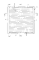
以下に本発明の好適な一実施形態を図面に基づいて説明すると、図1は本発明に係る可動ルーバー面格子の閉じた状態での正面図、図2は図1のX−X線拡大断面図、図3は図1のY−Y線拡大断面図、図4は図1のZ−Z線拡大断面図である。ここに示す可動ルーバー面格子は、建物躯体の窓開口部(図示せず)の室外側に設置されるもので、左右縦枠1,1と上下横枠2,3とからなる面格子周枠4を有し、この面格子周枠4内に、水平に延びる横長のルーバー5が上下多段状に配設されている。
A preferred embodiment of the present invention will be described below with reference to the drawings. FIG. 1 is a front view of the movable louvered surface grid according to the present invention in a closed state, and FIG. 3 is an enlarged sectional view taken along line YY of FIG. 1, and FIG. 4 is an enlarged sectional view taken along line ZZ of FIG. The movable louver plane lattice shown here is installed outside the window opening (not shown) of the building frame, and is a plane lattice peripheral frame composed of left and right
面格子周枠4の左右各縦枠1は、図4に示すように、横断面コ字状の縦枠本体1aと、この縦枠本体1aの開口部を塞ぐ内周側部材1bとからなるもので、内周側部材1bには両側端部に係嵌凹部a,aが設けてあって、両係嵌凹部a,aが、縦枠本体1aの開口部の両側に設けられた係嵌凸部b,bに係嵌されるようになっている。また、この内周側部材1bには長さ方向一定間隔おきに軸孔10が設けられている。
As shown in FIG. 4, the left and right
各ルーバー5は、図2及び図6の(a) に示すように、横断面が略楕円形の中空状に形成されたアルミニウム合金の押出形材からなるもので、その中空部内には、下記角筒状補強軸体9の四隅の夫々外隅部に係合する係合凹部7が形成されている。また各ルーバー5の両側端部には開口部の向きが互いに逆向きの係嵌溝部8,8が形成されていて、図2の実線図示のようにルーバー5が閉じた時に隣り合うルーバー5,5の対向する係嵌溝部8,8どうしが係嵌し合うようになっている。
As shown in FIGS. 2 and 6A, each
各ルーバー5には、図4に示すように、ルーバー5よりも長い金属製の補強軸体9が、ルーバー5の回転軸線Gに沿って一体回転可能に貫通され、この補強軸体9の両端部9a,9aは、面格子周枠4を構成する縦枠1,1の内周側部材1b,1bに設けてある軸孔10,10から夫々突出していると共に、軸受部材11,11を介して軸孔10,10に夫々回転可能に軸支され、その軸孔10,10から突出した補強軸体9の突出端部9a,9aには、クランクアーム12,12が夫々取付部材13,13を介して取り付けられ、各クランクアーム12は連杆14によって枢支連結されている。
As shown in FIG. 4, a metal reinforcing
補強軸体9は、鋼製又はステンレス製で横断面が正方形の角形管からなるもので、図4に示すように、ルーバー5の長さL05よりも長い長さL09を有する。各軸受部材11は、耐摩耗性及び摺動性に優れた合成樹脂によって形成されている。クランクアーム12及び取付部材13は、前記軸受部材11と同じような合成樹脂によって形成され、連杆14は鋼板又はステンレス板によって形成される。
The reinforcing
前記取付部材13は、図5の(a) 及び(c) に示すように、その一端面側に、補強軸体9の端部内に嵌合する嵌合突起部13aと補強軸体9の端部9aを受け入れる環状の受入溝部13bとを有し、他端面側に短四角柱状の嵌合凸部13cを有し、そして中心軸線に沿って両端面を貫くネジ孔13dを有する。
As shown in FIGS. 5 (a) and 5 (c), the
前記クランクアーム12も、図5の(a) 及び(c) に示すように、一端面側には、取付部材13の短四角柱状の嵌合凸部13cが嵌合する嵌合凹部12aを有し、他端面側には、ネジ具16を挿入する挿通部12bが嵌合凹部12aと同軸状に形成されると共に、ネジ具挿通部12bの下方側に連杆取付用突起15が突設され、この突起15には係止ヘッド15a及び割溝15bが形成されている。
As shown in FIGS. 5 (a) and 5 (c), the
面格子周枠4の縦枠1に対するルーバー5の取付け、このルーバー5を貫通する補強軸体9の取付け、及びこの補強軸体9に対するクランクアーム12の取付けについて図5の(a) 〜(c) を参照して説明すると、先ず、左右各縦枠1の内周側部材1bに設けてある各軸孔10に軸受部材11を同図の(a) に示すように嵌合しておき、また各ルーバー5には補強軸体9を貫通させて、その両端部9a,9aをルーバー5の両端から夫々突出させておく。
The attachment of the
ルーバー5の両端から夫々突出させた補強軸体9の端部9aを、左右各縦枠1の内周側部材1bに取り付けた軸受部材11に対しその内側から挿通させて外側へ突出させ、その突出端部9aに取付部材13を取り付ける。即ち、取付部材13の嵌合凸部13cを補強軸体9の端部9a内に嵌合させると共に、補強軸体9の端部9aを取付部材13の環状受入溝部13bに強く押し込むことによって、取付部材13を補強軸体9の端部9aに夫々取り付ける。
The
その後、クランクアーム12の嵌合凹部12aを取付部材13の嵌合凸部13cに対し嵌合し、ネジ具16をクランクアーム12のネジ具挿通部12bから取付部材13のネジ孔13dにねじ込んで締め付けることによって、クランクアーム12を取付部材13に固定する。
Thereafter, the fitting recess 12a of the
上記のように左右各縦枠1の内周側部材1bに取り付けた軸受部材11から突出させた補強軸体9の突出端部9aに取付部材13を介してクランクアーム12を取り付けた後、連杆14に長さ方向一定間隔おきに設けてある取付孔14a(長孔)を各クランクアーム12の連杆取付用突起15に嵌め込む。この場合、突起15には係止ヘッド15aに割溝15bが形成してあるから、この割溝15bを介して係止ヘッド15aを縮径した状態で取付孔14aを突起15に嵌め込めばよい。
After attaching the
上記のようにして面格子周枠4内に多段状に配設した多数のルーバー5を開閉操作するには、図示は省略するが、多数のルーバー5の何れか一つに取り付けてある開閉操作用のハンドルを操作することによって、全てのルーバー5を一斉に開閉させることができる。図2には全てのルーバー5が閉鎖した状態を実線で示し、開放した状態を仮想線で示す。閉鎖状態では、隣り合うルーバー5,5の対向する係嵌溝部8,8どうしが係嵌し合っている。
In order to open and close a large number of
以上説明したように、この可動ルーバー面格子は、各ルーバー5に、ルーバー5よりも長い横断面正方形の角形管からなる金属製の補強軸体9をルーバー5の回転軸線Gに沿って一体回転可能に貫通させ、この補強軸体9の両端部9a,9aを、面格子周枠4の内周側部材4aに設けた軸孔10から夫々突出させると共に、軸受部材11を介して軸孔10に回転可能に軸支し、その軸孔10から突出した補強軸体9の突出端部9aにクランクアーム12を取り付け、各クランクアーム12を連杆14により枢支連結してなるもので、図4からも分かるように、ルーバー5を貫通する金属製補強軸体9の両端部9a,9aが軸受部材11,11を介して面格子周枠4の内周側部材4aに軸支されているから、泥棒が面格子から室内に侵入するためにバールなどの工具を使ってルーバー5を破壊しようとしても、そのルーバー5の支軸部を例えば3〜5分の短時間で簡単容易に破壊することができず、そうこうしている間に、泥棒は、あきらめて逃げて行くか、そのうち警報などによって駆けつけた警察官に捕まえられることになる。
As described above, in this movable louvered surface lattice, each
上記実施形態の説明では、補強軸体9として、図6の(a) に示すような鋼製又はステンレス製で横断面が正方形の角形管からなる補強軸体9aを使用したが、本発明に係る補強軸体9としては、横断面が正方形の角形管以外に、図6の(b) に示すような横断面が正方形で中実状の補強軸体9bでもよいし、あるいは同図の(c) に示すような円管状の補強軸体9cでもよく、また同図の(d) に示すような横断面が円形で中実状の補強軸体9dでもよい。
In the description of the above embodiment, the reinforcing
尚、図6の(a) 及び(b) に示す補強軸体9a,9bのように、補強軸体9の横断面が四角角形である場合は、ルーバー5の中空部内に設けた係合凹部7を角形補強軸体9の四隅の夫々外隅部に係合させて、ルーバー5内に補強軸体9を回転不能に保持することができるが、図6の(c) 及び(d) に示す補強軸体9c,9dのように、補強軸体9の横断面が円形である場合は、そのままでは補強軸体9を回転不能に保持できないため、(c) 及び(d) に示すように、各補強軸体9c,9dの外周面の夫々少なくとも2箇所に係合凹条部17を設けると共に、この凹溝条17に係合する係合凸条部18をルーバー5の中空部内に設け、それによって補強軸体9c,9dをルーバー5内に回転不能に保持するようにしている。
In addition, when the cross section of the reinforcing
また、上記実施形態では、面格子周枠4内に夫々横長の多数のルーバー5を連動開閉可能に配設した可動ルーバー面格子について説明したが、本発明は、面格子周枠4内に夫々縦長の多数のルーバー5を連動開閉可能に配設した可動ルーバー面格子にも適用されるものである。
In the above-described embodiment, the movable louver surface lattice has been described in which a large number of horizontally
1 面格子周枠の左右縦枠
2 面格子周枠の上横枠
3 面格子周枠の下横枠
4 面格子周枠
5 ルーバー
9 補強軸体
10 軸孔
11 軸受部材
12 クランクアーム
14 連杆
DESCRIPTION OF
Claims (3)
各ルーバーにルーバーよりも長さの長い金属製補強軸体をルーバーの回転軸線に沿って一体回転可能に貫通させ、この補強軸体の両端部を、面格子周枠の内周側部材に設けた軸孔から夫々突出させると共に、軸受部材を介して軸孔に回転可能に軸支し、その軸孔から突出した補強軸体の突出端部にクランクアームを取り付け、各クランクアームを連杆によって枢支連結してなることを特徴とする可動ルーバー面格子。 In a movable louvered surface lattice in which a large number of hollow horizontally or vertically long louvers are arranged in a plane lattice peripheral frame so as to be able to interlock open and close,
Each louver is made to penetrate a metal reinforcing shaft that is longer than the louver so as to be integrally rotatable along the rotation axis of the louver, and both ends of the reinforcing shaft are provided on the inner peripheral side member of the surface lattice peripheral frame. And projecting from the shaft hole through a bearing member so as to be rotatably supported by the shaft hole, and attaching a crank arm to the projecting end of the reinforcing shaft projecting from the shaft hole. A movable louvered surface lattice characterized by being pivotally connected.
Priority Applications (1)
| Application Number | Priority Date | Filing Date | Title |
|---|---|---|---|
| JP2007213435A JP2009046868A (en) | 2007-08-20 | 2007-08-20 | Movable louver surface grating |
Applications Claiming Priority (1)
| Application Number | Priority Date | Filing Date | Title |
|---|---|---|---|
| JP2007213435A JP2009046868A (en) | 2007-08-20 | 2007-08-20 | Movable louver surface grating |
Publications (1)
| Publication Number | Publication Date |
|---|---|
| JP2009046868A true JP2009046868A (en) | 2009-03-05 |
Family
ID=40499336
Family Applications (1)
| Application Number | Title | Priority Date | Filing Date |
|---|---|---|---|
| JP2007213435A Pending JP2009046868A (en) | 2007-08-20 | 2007-08-20 | Movable louver surface grating |
Country Status (1)
| Country | Link |
|---|---|
| JP (1) | JP2009046868A (en) |
Cited By (2)
| Publication number | Priority date | Publication date | Assignee | Title |
|---|---|---|---|---|
| JP2015232201A (en) * | 2014-06-09 | 2015-12-24 | タキゲン製造株式会社 | Light quantity adjusting thermal insulation louver |
| KR20210038070A (en) * | 2019-09-30 | 2021-04-07 | 주식회사 다산월드 | Crime-prevention improvemented blade for louver system |
Citations (2)
| Publication number | Priority date | Publication date | Assignee | Title |
|---|---|---|---|---|
| JPH0191837A (en) * | 1987-10-02 | 1989-04-11 | Toshiba Corp | X-ray diagnostic apparatus |
| JPH03130230U (en) * | 1990-04-12 | 1991-12-27 |
-
2007
- 2007-08-20 JP JP2007213435A patent/JP2009046868A/en active Pending
Patent Citations (2)
| Publication number | Priority date | Publication date | Assignee | Title |
|---|---|---|---|---|
| JPH0191837A (en) * | 1987-10-02 | 1989-04-11 | Toshiba Corp | X-ray diagnostic apparatus |
| JPH03130230U (en) * | 1990-04-12 | 1991-12-27 |
Cited By (3)
| Publication number | Priority date | Publication date | Assignee | Title |
|---|---|---|---|---|
| JP2015232201A (en) * | 2014-06-09 | 2015-12-24 | タキゲン製造株式会社 | Light quantity adjusting thermal insulation louver |
| KR20210038070A (en) * | 2019-09-30 | 2021-04-07 | 주식회사 다산월드 | Crime-prevention improvemented blade for louver system |
| KR102271428B1 (en) * | 2019-09-30 | 2021-07-01 | 주식회사 다산월드 | Crime-prevention improvemented blade for louver system |
Similar Documents
| Publication | Publication Date | Title |
|---|---|---|
| JP2009046868A (en) | Movable louver surface grating | |
| US8082695B2 (en) | Mullion assembly for double door | |
| KR101230667B1 (en) | Removable safety rod | |
| JP2006022589A (en) | Resin sash | |
| JP6723096B2 (en) | Joinery | |
| JP2018105103A (en) | Door sheave and fitting | |
| JP3130230U (en) | Building louver | |
| US20030093871A1 (en) | Closure assembly | |
| JP2013040540A (en) | Ceiling inspection port frame | |
| JP3189155U (en) | Door with child door | |
| JP5193543B2 (en) | sash | |
| JP2017133263A (en) | Fitting | |
| JP4749264B2 (en) | Indoor lattice mounting mechanism | |
| JP4443338B2 (en) | Face lattice | |
| JP7225035B2 (en) | door | |
| JP2018003392A (en) | Fixture | |
| JP5016366B2 (en) | Strike hole adjustment mechanism | |
| JP5134332B2 (en) | Exterior structure and telescopic gate | |
| JP2008163549A (en) | Crime-prevention window | |
| JPH0750544Y2 (en) | Area lattice locking device | |
| JP2010261210A (en) | Device for mounting screen body | |
| JP4075703B2 (en) | Face lattice | |
| JP2008174951A (en) | Crime prevention window | |
| JP4726669B2 (en) | door | |
| KR200377441Y1 (en) | Pair glass window |
Legal Events
| Date | Code | Title | Description |
|---|---|---|---|
| A621 | Written request for application examination |
Free format text: JAPANESE INTERMEDIATE CODE: A621 Effective date: 20090423 |
|
| A977 | Report on retrieval |
Free format text: JAPANESE INTERMEDIATE CODE: A971007 Effective date: 20110525 |
|
| A131 | Notification of reasons for refusal |
Free format text: JAPANESE INTERMEDIATE CODE: A131 Effective date: 20110601 |
|
| A02 | Decision of refusal |
Free format text: JAPANESE INTERMEDIATE CODE: A02 Effective date: 20111026 |