JP2009041702A - Different pipe joint - Google Patents
Different pipe joint Download PDFInfo
- Publication number
- JP2009041702A JP2009041702A JP2007209291A JP2007209291A JP2009041702A JP 2009041702 A JP2009041702 A JP 2009041702A JP 2007209291 A JP2007209291 A JP 2007209291A JP 2007209291 A JP2007209291 A JP 2007209291A JP 2009041702 A JP2009041702 A JP 2009041702A
- Authority
- JP
- Japan
- Prior art keywords
- bayonet
- ring
- peripheral surface
- receiving port
- groove
- Prior art date
- Legal status (The legal status is an assumption and is not a legal conclusion. Google has not performed a legal analysis and makes no representation as to the accuracy of the status listed.)
- Pending
Links
Images


Abstract
Description
本発明は、異種管継手に係り、詳しくは、樹脂管からなる配管途中に配設される金属製バルブと樹脂管とを接合するための継手構造に関する。 The present invention relates to a dissimilar pipe joint, and more particularly to a joint structure for joining a metal valve and a resin pipe disposed in the middle of a pipe made of a resin pipe.
主として水道に使用する樹脂製の耐震管では、伸びが大きく地盤変位に追従する性能を有していることから、特にポリエチレン管の需要が伸びている。ポリエチレン管同士の接合は、ポリエチレン製の継手を使用した熱融着方式が主流であるが、金属製配管部材、例えば鋳鉄製バルブとポリエチレン管とを接合する際には、熱融着方式を用いることはできない。 Resin-made seismic pipes mainly used for water supply have a large elongation and the ability to follow the ground displacement, so the demand for polyethylene pipes is growing. The joining of polyethylene pipes is mainly performed by a heat fusion method using a polyethylene joint. However, when joining a metal piping member, for example, a cast iron valve and a polyethylene pipe, a heat fusion method is used. It is not possible.
このため、鋳鉄製バルブの受口の内周面に形成したゴム輪締付部にゴム輪を装着し、受口外周に設けたフランジ部と、受口の内周側に突出する押輪のフランジ部とを複数の締結ボルトで締め付け、前記ゴム輪を圧縮して内周方向に突出変形させることにより、受口に挿入したポリエチレン管の外周面にゴム輪を強く押し付けて受口にポリエチレン管を接続させるようにしたものがある(例えば、特許文献1参照。)。
しかし、上述のようにフランジを締結ボルトで締結するものでは、ボルトを所定の力で均等に締め付けないと、漏水や管の離脱が生じるおそれがあり、継手の性能は、ボルトの締付管理によって決まるといった問題があった。 However, in the case where the flange is fastened with fastening bolts as described above, if the bolts are not evenly tightened with a predetermined force, there is a risk of water leakage or pipe detachment. There was a problem of being decided.
そこで本発明は、鋳鉄製バルブなどの金属製受口とポリエチレン管などの樹脂管とを、締結ボルトを用いることなく簡単な構造で確実に接続することができ、地震等の外力が加わっても離脱や漏水の虞のない異種管継手を提供することを目的としている。 Therefore, the present invention can securely connect a metal receiving port such as a cast iron valve and a resin tube such as a polyethylene tube with a simple structure without using a fastening bolt, even if an external force such as an earthquake is applied. An object of the present invention is to provide a dissimilar pipe joint that is free from detachment and water leakage.
上記目的を達成するため、本発明は、金属製受口の内周面と、該金属製受口に挿入された樹脂管の外周面との間を、前記金属製受口の内周面に装着されたゴム輪にてシールする異種管継手において、前記金属製受口の端部外周面に突設したバヨネット爪と、該バヨネット爪にバヨネット結合されるバヨネット溝を有する環状連結部材と、該環状連結部材の内周に配設されるリング状係合部材と、バヨネット結合後の前記環状連結部材を回り止めする回止用ピースとを備え、該環状連結部材の内周には、前記リング状係合部材を収容する収容溝が形成されるとともに、該収容溝の内周面には、金属製受口側が漸次大径となり、該収容溝に収容した前記リング状係合部材を縮径させるための円錐部が設けられ、前記回止用ピースは、バヨネット結合後のバヨネット溝の開口部から隣接するバヨネット爪の間に挿入されることを特徴とし、前記リング状係合部材は、リングの一部を切り欠いてC字状に形成された本体部と、該本体部の外周に突設した係合突部と、前記本体部内周面の周方向に設けられて縮径時に前記樹脂管の外周面に食い込む係合爪部と、前記本体部外周面に設けられた金属製受口側が漸次大径となる円錐面とを有し、前記環状連結部材の内周には、前記係合突部が係合する係合凹部が金属製受口側に開口して形成されている。 In order to achieve the above object, the present invention provides an inner peripheral surface of the metal receiving port between the inner peripheral surface of the metal receiving port and the outer peripheral surface of the resin tube inserted into the metal receiving port. In the dissimilar pipe joint that is sealed by the attached rubber ring, a bayonet claw projecting from the outer peripheral surface of the end of the metal receiving port, an annular coupling member having a bayonet groove coupled to the bayonet claw, A ring-shaped engaging member disposed on the inner periphery of the annular connecting member; and a rotation-preventing piece for preventing the annular connecting member after the bayonet is joined. The ring is disposed on the inner periphery of the annular connecting member. A receiving groove for receiving the engagement member is formed, and a metal receiving side gradually increases in diameter on the inner peripheral surface of the receiving groove, and the ring-like engagement member received in the receiving groove is reduced in diameter. A conical portion is provided, and the turning piece has a bayonet connection. The ring-shaped engagement member is inserted between the adjacent bayonet claws from the opening of the rear bayonet groove, and the ring-shaped engagement member has a body portion formed in a C shape by cutting out a part of the ring, An engaging protrusion projecting from the outer periphery of the main body, an engaging claw provided in the circumferential direction of the inner peripheral surface of the main body and biting into the outer peripheral surface of the resin tube when the diameter is reduced, and an outer peripheral surface of the main body The provided metal receiving side has a conical surface with a gradually increasing diameter, and an engagement recess that engages with the engaging projection opens on the inner side of the annular coupling member on the metal receiving side. Is formed.
本発明の異種管継手によれば、金属製受口と環状連結部材とをバヨネット結合させることによって両者を接続できるので、作業管理が簡略化できるとともに、接続作業の大幅な簡略化及び時間短縮が図れる。また、バヨネット結合に伴ってリング状係合部材が縮径して樹脂管を締め付けるので、金属製受口から樹脂管が離脱したり、漏水したりすることを確実に防止でき、さらに、回止用ピースを挿入することにより、地震等の外力により環状連結部材が回動して緩むことを防止できる。 According to the dissimilar pipe joint of the present invention, the metal receiving port and the annular connecting member can be connected by bayonet connection, so that the work management can be simplified and the connection work can be greatly simplified and the time can be shortened. I can plan. In addition, the ring-shaped engagement member shrinks with the bayonet connection and tightens the resin tube, so that it is possible to reliably prevent the resin tube from detaching from the metal receiving port or leaking water, and to stop the rotation. By inserting the use piece, the annular connecting member can be prevented from rotating and loosening due to an external force such as an earthquake.
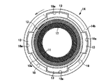
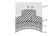
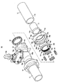
図1は本発明の異種管継手の一形態例を示すもので、図1は異種管継手の接続状態を示す断面図、図2はバヨネット結合前の状態を示す説明図、図3はバヨネット結合後の状態を示す図1のIII-III断面図、図4は図1のIV-IV断面図、図5は環状連結部材、リング状係合部材及び樹脂管の連結状態を示す要部拡大図、図6は鋳鉄製のバルブにポリエチレン管を接続した状態を示す一部断面正面図、図7は異種管継手の分解斜視図である。 FIG. 1 shows an example of a dissimilar pipe joint according to the present invention. FIG. 1 is a cross-sectional view showing a connection state of dissimilar pipe joints, FIG. 2 is an explanatory view showing a state before bayonet joining, and FIG. 3 is a bayonet joint. 1 is a sectional view taken along the line III-III in FIG. 1, FIG. 4 is a sectional view taken along the line IV-IV in FIG. 1, and FIG. 5 is an enlarged view of the main part showing the connected state of the annular connecting member, ring-shaped engaging member and resin pipe. 6 is a partially sectional front view showing a state in which a polyethylene pipe is connected to a cast iron valve, and FIG. 7 is an exploded perspective view of a dissimilar pipe joint.
本形態例は、鋳鉄製のバルブ10に設けられた金属製の受口10aに樹脂管であるポリエチレン管11の一端(挿口11a)を挿入して接続するものであって、受口10aの内周面に装着されるゴム輪12と、受口10aの端部外周面に突設したバヨネット爪13にバヨネット結合される環状連結部材14と、受口10aと環状連結部材14とのバヨネット結合に伴って縮径し、ポリエチレン管11を締め付けて抜け止めするリング状係合部材15と、バヨネット結合後の環状連結部材14を回り止めする回止用ピース16と、ポリエチレン管11に挿入されるインナコア17とを備えている。
In this embodiment, one end (
バルブ10は、両端に受口10aを有する直管状の弁箱10bの中央部に弁部を設けた内ネジ式仕切弁であって、通常の内ネジ式仕切弁と同様に、弁棒の上端に取り付けられたキャップ10cに開栓器を装着し、開栓器を操作して弁棒を回動することにより、弁体を上下動させて流路の開閉を行うように形成されている。
The
前記受口10aは、弁箱10bの内径よりも大径で、接続されるポリエチレン管11の外径に対応した内径を有し、先端側の内周面に周方向に形成されるゴム輪装着溝10dと、先端側外周面に周方向に等間隔で突設される4つのバヨネット爪13とを備え、前記ゴム輪装着溝10dにゴム輪12が装着されている。
The
環状連結部材14は、中央にポリエチレン管11の挿通孔14aを備えた金属製の筒状体であって、受口側端面14bには前記バヨネット爪13を挿入する4つのバヨネット溝18の開口部18aが設けられている。バヨネット溝18は、バヨネット爪13の厚さより僅かに大きく設定され、バヨネット結合時の環状連結部材14の回動操作を容易に行えるようにしている。
The annular connecting
さらに、環状連結部材14の内周には、前記リング状係合部材15を収容する収容溝14cが受口側端面14b側に開口して形成され、該収容溝14cには、リング状係合部材15の係合突部15aが係合する係合凹部14dが形成されるとともに、収容溝14cの内周面には受口側端面14b側が漸次大径となる円錐部14eと、円錐部14eの大径側から受口側端面14bに連続した円筒部14fとが設けられている。また、環状連結部材14の外周には、回動操作用の突出部14gが周方向に複数設けられている。
Further, an
リング状係合部材15は、リングの一部を切り欠いた切欠き部15cを有するC字状に形成された本体部15fと、該本体部15fの前記切欠き部15cと対向する外周部に突設した前記係合突部15aと、本体部15fの内周面の周方向に設けられた係合爪部15dと、本体部15fの外周面に設けられた受口10a側が漸次大径となる円錐面15bと、円錐面15bの大径側から受口10a側に連続した円筒面15gとを有しており、前記係合爪部15dの一部には、爪部を形成しない平面部15eが軸方向に設けられている。
The ring-
リング状係合部材15における円錐面15bの一端最小径部分の外径は、収容溝14cの円筒部14fの内径より小さく形成され、円筒面15gの外径は、円筒部14fの内径より大きく形成されている。したがって、リング状係合部材15を収容溝14cに収容する際には、初期には円錐面15bの一端最小径部分側から円錐面15bの途中までが収容溝14cに収容され、リング状係合部材15の内径をポリエチレン管11が通過可能な大きさに保った状態になり、バヨネット結合後に円錐面15bが収容溝14cの円錐部14eに押圧されて縮径することにより、円筒面15gが円筒部14fの内周に収まり、リング状係合部材15の係合爪部15dをポリエチレン管11の外周面に所定量食い込ませるように形成されている。
The outer diameter of the one end minimum diameter portion of the
ゴム輪12は、ゴム輪装着溝10dの受口開口側に形成された係止溝10eに嵌入係合するヒール部12aと、ゴム輪装着溝10dの底面とポリエチレン管11の挿口11aの外周面との間で圧縮されてシール面圧を生ずるバルブ部12bとを備えている。
The
回止用ピース16は、ゴムなどの弾性材料で形成されており、受口10aと環状連結部材14とをバヨネット結合した後、バヨネット爪13とバヨネット溝18の開口部18aとの間に形成される空間部に弾性変形させながら圧入することにより、両者の間の空間部に隙間なく挿入できるように形成されている。
The
インナコア17は、ポリエチレン管11の内径よりも僅かに小径の金属製の円筒体からなるもので、その先端には、外周側に折り返されて折り返し端が挿口11aの先端面外周に当接するガイド片17aが形成されている。このインナコア17は、これをポリエチレン管11の挿口11aに嵌入することにより、地震などの外力でポリエチレン管11が変形することを防止し、係合爪部15dの離脱を阻止するとともにゴム輪12とのシール性を確保することができる。また、外周に円錐面を有するガイド片17aをインナコア17の先端に設けることにより、挿口11aの先端外周を面取りすることなく、ゴム輪12を挿口11aの外周面に向けて容易に通過させることができる。
The
受口10aにポリエチレン管11を接続する際には、ポリエチレン管11の挿口先端部にインナコア17を挿入し、インナコア17のガイド片17aをポリエチレン管11の先端面外周部に当接させる。また、ポリエチレン管11の挿口11aを環状連結部材14の挿通孔14aに挿通し、さらに、挿通孔14aから突出したポリエチレン管11の先端側をリング状係合部材15に挿通する。この状態で、ゴム輪装着溝10dにゴム輪12を装着した受口10a内に挿口11aを所定量挿入することにより、ゴム輪12のバルブ部12aがゴム輪装着溝10dの底面とポリエチレン管11の挿口11aの外周面との間で圧縮され、受口10aと挿口11aとが液密に接続された状態になる。
When connecting the
そして、リング状係合部材15の係合突部15aを環状連結部材14の係合凹部14dに係合させてリング状係合部材15を環状連結部材14の収容溝14c内に緩く収容した後、環状連結部材14を受口10aの方向に移動させ、バヨネット溝18の開口部18aとバヨネット爪13との位置を合わせ、環状連結部材14を押圧しながら、突出部14gを利用して所定の方向に回すことにより、バヨネット爪13とバヨネット溝18とをバヨネット結合させる。
Then, after engaging the
このようにして環状連結部材14を受口10aにバヨネット結合することにより、リング状係合部材15が収容溝14c内に略完全に収容された状態になるとともに、環状連結部材14の円錐部14eがリング状係合部材15の円錐面15bを押圧し、リング状係合部材15を受口10aの方向に押圧しながらリング状係合部材15をポリエチレン管11の外周面に向けて縮径させ、係合爪部15dをポリエチレン管11の外周面に食い込ませた状態になる。バヨネット結合後は、バヨネット溝18の各開口部18aから各バヨネット爪13間に回止用ピース16をそれぞれ挿入し、環状連結部材14を回り止めする。
In this way, the annular connecting
このように、金属製の受口10aとポリエチレン管11とをボルトやナットを用いることなく簡単に接続することができるため、作業管理が簡略化できるとともに、接続作業を大幅に軽減することができる。また、環状連結部材14の内周とリング状係合部材15の外周とに円筒部14f及び円筒面15gをそれぞれ設けたことにより、バヨネット爪13及びバヨネット溝18の製造精度によって隙間18bが生じた場合でも、リング状係合部材15が一定以上拡径せず、ポリエチレン管11に対する係合爪部15dの食い込み量を最低限確保することができる。さらに、環状連結部材14の内周とリング状係合部材15の外周とに円錐部14e及び円錐面15bをそれぞれ設けたことにより、ポリエチレン管11に地震等で引き抜き力が加わったときに、リング状係合部材15が縮径されることでより強い締付力が働き、高い離脱防止性能を得ることができる。
As described above, since the
また、環状連結部材14と受口10aとをバヨネット結合させた後、バヨネット爪13とバヨネット溝18の開口部18aとの間の空間部に回止用ピース16を挿入することから、地震等の外力が加わることがあっても、環状連結部材14が回動して緩むことがなく離脱や漏水を生じるおそれもない。
In addition, since the annular connecting
さらに、環状連結部材14と受口10aとをバヨネット結合させるのに伴って、リング状係合部材15の係合爪部15dがポリエチレン管11の外周面に食い込むことから、ポリエチレン管11の離脱を確実に防止することができる。また、リング状係合部材15は、環状連結部材14の係合凹部14dに係合突部15aを挿入していることから、環状連結部材14に対して回り止めされるとともに、リング状係合部材15の内周部に形成した平面部15eにはポリエチレン管11が食い込まないことから、係合爪部15dが食い込まない部分とポリエチレン管11に食い込んだ係合爪部15dの側面とでポリエチレン管11とバルブ10との相対的な回り止めを図ることができる。また、インナコア17の先端に、先端が小径となる円錐面を外周に有するガイド片17aを設けているので、挿口11aの先端外周角部を面取りしなくても、ゴム輪12を傷付けることなく挿口11aを受口10a内に容易に挿入することができ、作業性が向上する。
Further, as the annular connecting
なお、本発明の異種管継手は、バルブの金属製受口に樹脂管を接続するものに限らず、他の各種金属製配管部材の受口に樹脂管を接続する際にも適用でき、樹脂管にはポリエチレン管以外の樹脂管にも適用できる。また、リング状係合部材は、適宜な硬質合成樹脂や金属によって形成することができる。 The dissimilar pipe joint of the present invention is not limited to connecting a resin pipe to the metal receiving port of the valve, but can be applied to connecting a resin pipe to the receiving port of other various metal piping members. The pipe can be applied to resin pipes other than polyethylene pipes. Further, the ring-shaped engaging member can be formed of an appropriate hard synthetic resin or metal.
10…バルブ、10a…受口、10b…弁箱、10c…キャップ、10d…ゴム輪装着溝、10e…係止溝、11…ポリエチレン管、11a…挿口、12…ゴム輪、12a…ヒール部、12b…バルブ部、13…バヨネット爪、14…環状連結部材、14a…挿通孔、14b…受口側端面、14c…収容溝、14d…係合凹部、14e…円錐部、14f…円筒部、14g…突出部、15…リング状係合部材、15a…係合突部、15b…円錐面、15c…切欠き部、15d…係合爪部、15e…平面部、15f…本体部、15g…円筒面、16…回止用ピース、17…インナコア、17a…ガイド片、18…バヨネット溝、18a…開口部、18b…隙間
DESCRIPTION OF
Claims (2)
Priority Applications (1)
| Application Number | Priority Date | Filing Date | Title |
|---|---|---|---|
| JP2007209291A JP2009041702A (en) | 2007-08-10 | 2007-08-10 | Different pipe joint |
Applications Claiming Priority (1)
| Application Number | Priority Date | Filing Date | Title |
|---|---|---|---|
| JP2007209291A JP2009041702A (en) | 2007-08-10 | 2007-08-10 | Different pipe joint |
Publications (1)
| Publication Number | Publication Date |
|---|---|
| JP2009041702A true JP2009041702A (en) | 2009-02-26 |
Family
ID=40442641
Family Applications (1)
| Application Number | Title | Priority Date | Filing Date |
|---|---|---|---|
| JP2007209291A Pending JP2009041702A (en) | 2007-08-10 | 2007-08-10 | Different pipe joint |
Country Status (1)
| Country | Link |
|---|---|
| JP (1) | JP2009041702A (en) |
Cited By (4)
| Publication number | Priority date | Publication date | Assignee | Title |
|---|---|---|---|---|
| JP2015183731A (en) * | 2014-03-20 | 2015-10-22 | コスモ工機株式会社 | Pipe connection structure |
| JP2016159940A (en) * | 2015-02-27 | 2016-09-05 | 株式会社吉野工業所 | Slit valve cap |
| CN107575680A (en) * | 2017-09-21 | 2018-01-12 | 安徽荣达阀门有限公司 | A kind of valve with quick coupling device |
| CN111594434A (en) * | 2019-02-20 | 2020-08-28 | 东莞市海亿五金塑胶有限公司 | Novel well pump body subassembly |
-
2007
- 2007-08-10 JP JP2007209291A patent/JP2009041702A/en active Pending
Cited By (4)
| Publication number | Priority date | Publication date | Assignee | Title |
|---|---|---|---|---|
| JP2015183731A (en) * | 2014-03-20 | 2015-10-22 | コスモ工機株式会社 | Pipe connection structure |
| JP2016159940A (en) * | 2015-02-27 | 2016-09-05 | 株式会社吉野工業所 | Slit valve cap |
| CN107575680A (en) * | 2017-09-21 | 2018-01-12 | 安徽荣达阀门有限公司 | A kind of valve with quick coupling device |
| CN111594434A (en) * | 2019-02-20 | 2020-08-28 | 东莞市海亿五金塑胶有限公司 | Novel well pump body subassembly |
Similar Documents
| Publication | Publication Date | Title |
|---|---|---|
| TWI475171B (en) | Fluid coupling and retainer for fluid coupling | |
| JP2007155044A (en) | Pipe joint locking device | |
| JP4939826B2 (en) | How to assemble pipe fittings | |
| KR200463219Y1 (en) | Connection Port of Pipe | |
| JP4519781B2 (en) | Pipe fitting | |
| JP2009041702A (en) | Different pipe joint | |
| JP3188002B2 (en) | Pipe fittings | |
| US8056939B2 (en) | Plug connector for piping | |
| JP2001124258A (en) | Pipe joint | |
| JP5269178B2 (en) | How to assemble pipe fittings | |
| JP2016200159A (en) | Pipe joint | |
| JP6525636B2 (en) | How to connect backup ring, fittings and pipes | |
| JP6343131B2 (en) | Fitting | |
| JP5818855B2 (en) | Pipe fitting | |
| JP2005061549A (en) | Pipe joint structure for valve and resin pipe, and connecting method using the same | |
| JP2002039467A (en) | Sleeve type pipe joint | |
| JP2003227592A (en) | Pipe joint | |
| JP2007192368A (en) | Pipe joint | |
| JP2000266252A (en) | Pipe joint | |
| JP2007255684A (en) | Pipe joint | |
| JP4810267B2 (en) | Pipe fitting | |
| JP6168465B2 (en) | Pipe fitting | |
| KR200319225Y1 (en) | pipe fitting | |
| JPH09257171A (en) | Tube connecting structure | |
| JP2008157437A (en) | Pipe joint |