JP2009041406A - Exhaust emission control device - Google Patents

Exhaust emission control device Download PDF

Info

Publication number
JP2009041406A
JP2009041406A JP2007205772A JP2007205772A JP2009041406A JP 2009041406 A JP2009041406 A JP 2009041406A JP 2007205772 A JP2007205772 A JP 2007205772A JP 2007205772 A JP2007205772 A JP 2007205772A JP 2009041406 A JP2009041406 A JP 2009041406A
Authority
JP
Japan
Prior art keywords
exhaust
exhaust gas
passage
valve
container
Prior art date
Legal status (The legal status is an assumption and is not a legal conclusion. Google has not performed a legal analysis and makes no representation as to the accuracy of the status listed.)
Withdrawn
Application number
JP2007205772A
Other languages
Japanese (ja)
Inventor
Yoshiro Kato
吉郎 加藤
Current Assignee (The listed assignees may be inaccurate. Google has not performed a legal analysis and makes no representation or warranty as to the accuracy of the list.)
Toyota Motor Corp
Original Assignee
Toyota Motor Corp
Priority date (The priority date is an assumption and is not a legal conclusion. Google has not performed a legal analysis and makes no representation as to the accuracy of the date listed.)
Filing date
Publication date
Application filed by Toyota Motor Corp filed Critical Toyota Motor Corp
Priority to JP2007205772A priority Critical patent/JP2009041406A/en
Publication of JP2009041406A publication Critical patent/JP2009041406A/en
Withdrawn legal-status Critical Current

Links

Images

Classifications

    • YGENERAL TAGGING OF NEW TECHNOLOGICAL DEVELOPMENTS; GENERAL TAGGING OF CROSS-SECTIONAL TECHNOLOGIES SPANNING OVER SEVERAL SECTIONS OF THE IPC; TECHNICAL SUBJECTS COVERED BY FORMER USPC CROSS-REFERENCE ART COLLECTIONS [XRACs] AND DIGESTS
    • Y02TECHNOLOGIES OR APPLICATIONS FOR MITIGATION OR ADAPTATION AGAINST CLIMATE CHANGE
    • Y02ATECHNOLOGIES FOR ADAPTATION TO CLIMATE CHANGE
    • Y02A50/00TECHNOLOGIES FOR ADAPTATION TO CLIMATE CHANGE in human health protection, e.g. against extreme weather
    • Y02A50/20Air quality improvement or preservation, e.g. vehicle emission control or emission reduction by using catalytic converters

Abstract

<P>PROBLEM TO BE SOLVED: To eliminate NOx in exhaust gas by using, as reducing components, the hydrocarbon compounds contained in the exhaust gas in an exhaust emission control system for purifying the exhaust gas from the internal combustion engine of a vehicle. <P>SOLUTION: This exhaust emission control system comprises an upstream side control part 44 and a downstream side control part 46 including a catalyst having an NOx eliminating performance which are connected in series in an exhaust passage 35. The exhaust emission control system further comprises a collection passage 47 which communicates with an exhaust passage E1 on the upstream side of the upstream side control part 44 and in which a collection valve 52 is installed, a container 50 communicating with the other end of the collection passage 47, a discharge passage 56 which communicates with the container 50, which communicates with an exhaust passage E2 between the upstream side control part 44 and the downstream side control part 46, and in which a release valve 60 is installed, and a release valve control means for controllably opening the release valve 60 to release the discharge gas including the reducing components in the container 50. The exhaust gas is collected from the exhaust passage E1 into the container 50 during the start of the engine and during the accelerating operation. <P>COPYRIGHT: (C)2009,JPO&INPIT

Description

本発明は、内燃機関から排出される排気ガス中のNOxを浄化するために用いられる排気ガス浄化システムに関する。   The present invention relates to an exhaust gas purification system used for purifying NOx in exhaust gas discharged from an internal combustion engine.

内燃機関の排気ガス中のNOxを浄化させる触媒として、NOx吸蔵還元型触媒や選択還元型NOx触媒が知られている。NOx吸蔵還元型触媒では、既知のように、NOxが硝酸塩として触媒中に吸蔵され、例えば一時的に排気ガスをリッチ雰囲気とすることでその硝酸塩が分解されてNOxが放出され、そのNOx吸蔵能が回復されると共に、NOxは雰囲気中に存在するHC、COなどの還元成分と反応してN2に還元浄化される。他方、選択還元型NOx触媒では、酸素過剰な雰囲気であり且つ還元剤の存在下でNOxが還元または分解される。 As a catalyst for purifying NOx in exhaust gas of an internal combustion engine, a NOx occlusion reduction type catalyst and a selective reduction type NOx catalyst are known. In a NOx occlusion reduction type catalyst, as is known, NOx is occluded in the catalyst as nitrate, for example, the exhaust gas is temporarily made rich to decompose the nitrate to release NOx, and the NOx occlusion capacity Is recovered and NOx reacts with reducing components such as HC and CO present in the atmosphere to be reduced and purified to N 2 . On the other hand, in the selective reduction type NOx catalyst, NOx is reduced or decomposed in an oxygen-excess atmosphere and in the presence of a reducing agent.

例えば、特許文献1に、選択還元型NOx触媒を有する内燃機関の排気浄化装置が開示されている。この装置は、ゲル状の還元剤を貯蔵する還元剤貯蔵室と、この還元剤貯蔵室に貯蔵されたゲル状の還元剤を選択還元型NOx触媒上流側の排気通路に供給する還元剤供給手段とを備えている。そして、このゲル状の還元剤としてゲル状の尿素が用いられ、このゲル状の尿素は、機関運転状態から導出されたNOx排出量、あるいは、NOxセンサで検出した排気ガスのNOx濃度に基づいて演算されたNOx排出量に応じた分、供給されるようにされている。   For example, Patent Document 1 discloses an exhaust purification device for an internal combustion engine having a selective reduction type NOx catalyst. The apparatus includes a reducing agent storage chamber for storing a gel-like reducing agent, and a reducing agent supply means for supplying the gel-like reducing agent stored in the reducing agent storage chamber to an exhaust passage upstream of the selective reduction type NOx catalyst. And. Gelled urea is used as the gelled reducing agent, and this gelled urea is based on the NOx emission amount derived from the engine operating state or the NOx concentration of the exhaust gas detected by the NOx sensor. An amount corresponding to the calculated amount of NOx emission is supplied.

特開2000−310112号公報JP 2000-310112 A

しかしながら、上記特許文献1に記載の装置では、貯蔵されている還元剤の量が低下して所定量を下回るようなときには、そのためだけにそれを外部から補充することが必要とされる。したがって、運転者が、特許文献1に記載の装置を用いるときに、煩わしさを感じる可能性がある。   However, in the apparatus described in Patent Document 1, when the amount of stored reducing agent falls below a predetermined amount, it is necessary to replenish it from the outside only for that purpose. Therefore, there is a possibility that the driver feels troublesome when using the device described in Patent Document 1.

それ故、還元剤として、外部から補充するものではなく、内燃機関で通常生成されるあるいは用いられるものを用いることが望まれる。例えば、内燃機関の燃料を、還元剤として、排気通路に直接的に供給することが考えられる。しかしながら、これでは燃料消費量が増大することになるので、燃費向上の点からは好ましいとはいい難い。   Therefore, it is desirable to use a reducing agent that is normally generated or used in an internal combustion engine, rather than being replenished from the outside. For example, it is conceivable to directly supply the fuel of the internal combustion engine to the exhaust passage as a reducing agent. However, this increases the amount of fuel consumed, which is not preferable from the viewpoint of improving fuel consumption.

ところで、車両に搭載された内燃機関の排気ガスには炭化水素化合物や一酸化炭素などが含まれ得、運転状態等によっては燃焼室から排出されたばかりの排気ガスのそれらの濃度はかなり高くなる。それ故、このような成分を含む排気ガスを上記還元剤として用いることが望まれる。   By the way, the exhaust gas of the internal combustion engine mounted on the vehicle may contain a hydrocarbon compound, carbon monoxide, and the like, and the concentration of the exhaust gas just exhausted from the combustion chamber becomes considerably high depending on the operation state or the like. Therefore, it is desirable to use exhaust gas containing such components as the reducing agent.

そこで、本発明はかかる点に鑑みて創案されたものであり、その目的は、排気ガス中に含まれる炭化水素化合物や一酸化炭素などを還元成分として用いて、排気ガス中のNOxを浄化することにある。   Accordingly, the present invention has been made in view of such a point, and an object of the present invention is to purify NOx in exhaust gas by using a hydrocarbon compound or carbon monoxide contained in the exhaust gas as a reducing component. There is.

上記目的を達成するために、本発明の排気ガス浄化システムは、内燃機関の排気通路に直列的に配置された上流側浄化部および下流側浄化部を備え、該下流側浄化部がNOx浄化能力を有する触媒を含む、排気ガス浄化システムにおいて、前記上流側浄化部上流側の排気通路に一端部が連通されると共に回収弁が設けられた回収通路と、該回収通路の他端部が連通された排気ガス収容容器と、該排気ガス収容容器に一端部が連通されると共に他端部が前記上流側浄化部および前記下流側浄化部の間の排気通路に連通されて放出弁が設けられた放出通路と、前記排気ガス収容容器内の還元成分を含む排気ガスを放出するべく前記放出弁を開弁制御する放出弁制御手段とを備えることを特徴とする。   In order to achieve the above object, an exhaust gas purification system of the present invention includes an upstream purification unit and a downstream purification unit arranged in series in an exhaust passage of an internal combustion engine, and the downstream purification unit has a NOx purification capability. In the exhaust gas purification system including the catalyst, the recovery passage provided with a recovery valve and the other end of the recovery passage are connected to the exhaust passage upstream of the upstream purification section. The exhaust gas storage container is connected to one end of the exhaust gas storage container and the other end is connected to the exhaust passage between the upstream purification unit and the downstream purification unit, and a discharge valve is provided. It is characterized by comprising a discharge passage and a discharge valve control means for controlling the opening of the discharge valve so as to release the exhaust gas containing the reducing component in the exhaust gas storage container.

上記構成によれば、排気ガス収容容器内の還元成分を含む排気ガスを上流側浄化部および前記下流側浄化部の間の排気通路に放出するべく放出弁制御手段により前記放出弁が開弁制御されるので、下流側浄化部に還元成分を含む排気ガスが供給される。したがって、下流側浄化部のNOx浄化能力を有する触媒では、排気ガス中の還元成分を用いて、排気ガス中のNOxを浄化することが可能になる。   According to the above configuration, the release valve is controlled to be opened by the release valve control means so as to release the exhaust gas containing the reducing component in the exhaust gas storage container into the exhaust passage between the upstream side purification unit and the downstream side purification unit. Therefore, the exhaust gas containing the reducing component is supplied to the downstream purification unit. Therefore, the catalyst having the NOx purification capability of the downstream side purification unit can purify NOx in the exhaust gas by using the reducing component in the exhaust gas.

なお、前記上流側浄化部は、酸化能力あるいはPM捕集機能を有するように構成されていると良い。こうすることで、排気ガス収容容器内に回収されなかった排気ガス中の炭化水素化合物、一酸化炭素あるいはPM(粒子状物質)を上流側浄化部で浄化することが可能になる。   The upstream purification unit may be configured to have an oxidation capability or a PM trapping function. By doing so, it becomes possible to purify the hydrocarbon compound, carbon monoxide or PM (particulate matter) in the exhaust gas that has not been collected in the exhaust gas storage container in the upstream purification unit.

上記排気ガス浄化システムは、前記回収通路に設けられた前記回収弁の開度を制御する回収弁制御手段をさらに備え、該回収弁制御手段は、機関始動時あるいは加速運転時に、前記回収弁を開弁制御すると良い。機関始動時あるいは加速運転時には炭化水素化合物や一酸化炭素などの還元成分の濃度が高い排気ガスが概して燃焼室から排気通路へ排出されるので、こうすることで、より多くの還元成分を含む排気ガスを回収することが可能になる。   The exhaust gas purification system further includes recovery valve control means for controlling the opening degree of the recovery valve provided in the recovery passage, and the recovery valve control means controls the recovery valve during engine start-up or acceleration operation. It is good to control valve opening. Exhaust gas with a high concentration of reducing components such as hydrocarbon compounds and carbon monoxide is generally discharged from the combustion chamber to the exhaust passage during engine start-up or acceleration operation. By doing so, exhaust gas containing more reducing components The gas can be recovered.

さらに、上記種々の排気ガス浄化システムは、前記内燃機関の排気通路の内、前記上流側浄化部上流側の排気通路と前記回収通路との連通箇所よりも下流側に設けられた排気絞り弁と、該排気絞り弁の開度を制御する排気絞り弁制御手段とをさらに備え、該排気絞り弁制御手段は、機関始動時に、前記排気絞り弁を閉弁制御すると良い。こうすることで、排気絞り弁上流側の排気通路の排気ガスの圧力を高めることが可能になる。したがって、上記の如く、機関始動時に概して燃焼室から排気通路へ排出された還元成分の濃度の高い排気ガスを、より高い圧力を有する状態で、回収することが可能になる。   Further, the various exhaust gas purification systems include an exhaust throttle valve provided downstream of a communication point between the exhaust passage upstream of the upstream purification unit and the recovery passage in the exhaust passage of the internal combustion engine. And an exhaust throttle valve control means for controlling the opening degree of the exhaust throttle valve, and the exhaust throttle valve control means preferably controls the exhaust throttle valve to be closed when the engine is started. By doing so, it becomes possible to increase the pressure of the exhaust gas in the exhaust passage upstream of the exhaust throttle valve. Therefore, as described above, the exhaust gas having a high concentration of the reducing component discharged from the combustion chamber to the exhaust passage at the time of starting the engine can be recovered with a higher pressure.

加えて、上記種々の排気ガス浄化システムにおいて、前記放出通路の排気通路側の前記他端部に1つあるいは複数の噴出口が設けられていると良い。こうすることで、放出通路から排出された排気ガスと、上流側から排気ガス収容容器を介さずに流れてきた排気ガスとのミキシングを効果的に生じさせることが可能になる。特に、前記噴出口は、前記上流側浄化部および前記下流側浄化部の間の前記排気通路に形成される排気通路縮小部近傍に位置されると良い。こうすることで、それらのミキシングをより効果的に生じさせることができる。   In addition, in the various exhaust gas purification systems described above, one or a plurality of jet outlets may be provided at the other end portion of the discharge passage on the exhaust passage side. By doing so, it becomes possible to effectively mix the exhaust gas discharged from the discharge passage and the exhaust gas flowing from the upstream side without passing through the exhaust gas storage container. In particular, the jet port may be positioned in the vicinity of an exhaust passage reduction portion formed in the exhaust passage between the upstream purification unit and the downstream purification unit. By doing so, they can be mixed more effectively.

本発明の好適な実施形態を添付図面に基づいて詳細に説明する。   Preferred embodiments of the present invention will be described in detail with reference to the accompanying drawings.

まず、第1実施形態を説明する。第1実施形態の排気ガス浄化システムが適用された車両の内燃機関システムの概略構成を図1に示す。内燃機関10は、燃料である軽油を燃料噴射弁12から圧縮状態にある燃焼室14内に直接噴射することにより自然着火させる型式の内燃機関、すなわちディーゼル機関である。なお、図1では、1つの気筒16に関してのみ表されているけれども、内燃機関10は複数の気筒を有し得、例えば4気筒機関である。   First, the first embodiment will be described. FIG. 1 shows a schematic configuration of an internal combustion engine system for a vehicle to which the exhaust gas purification system of the first embodiment is applied. The internal combustion engine 10 is a type of internal combustion engine, that is, a diesel engine, that spontaneously ignites by directly injecting light oil as fuel into a combustion chamber 14 in a compressed state from a fuel injection valve 12. Although only one cylinder 16 is shown in FIG. 1, the internal combustion engine 10 can have a plurality of cylinders, for example, a four-cylinder engine.

気筒16の燃焼室14に臨むと共に吸気通路18の一部を区画形成する吸気ポート20は、シリンダヘッド22に形成されていて、動弁機構23によって駆動される吸気弁24によって開閉される。シリンダヘッド22には、吸気通路18の一部を区画形成する吸気マニフォルド26が接続され、さらにその上流側には同じく吸気通路18の一部を区画形成する吸気管28が接続されている。吸気管28の上流端側には、吸気通路18に導かれる空気中の塵埃などを除去するべくエアクリーナ30が設けられている。また、スロットルアクチュエータ32によって開度が調整されるスロットル弁34が、吸気管28の途中に設けられている。   An intake port 20 facing the combustion chamber 14 of the cylinder 16 and defining a part of the intake passage 18 is formed in the cylinder head 22 and is opened and closed by an intake valve 24 driven by a valve mechanism 23. An intake manifold 26 that defines a part of the intake passage 18 is connected to the cylinder head 22, and an intake pipe 28 that also defines a part of the intake passage 18 is connected to the upstream side thereof. An air cleaner 30 is provided on the upstream end side of the intake pipe 28 to remove dust and the like in the air guided to the intake passage 18. A throttle valve 34 whose opening is adjusted by the throttle actuator 32 is provided in the middle of the intake pipe 28.

他方、気筒16の燃焼室14に臨むと共に排気通路35の一部を区画形成する排気ポート36は、シリンダヘッド22に形成されていて、動弁機構23によって駆動される排気弁38によって開閉される。シリンダヘッド22には、排気通路35の一部を区画形成する排気マニフォルド40が接続され、さらにその下流側には同じく排気通路35の一部を区画形成する排気管42が接続されている。排気管42の途中には、排気ガスを浄化するための浄化装置が設けられている。浄化装置は2つの浄化部を直列的に備え、それら2つの浄化部は上流側から順に上流側浄化部44、下流側浄化部46である。   On the other hand, an exhaust port 36 facing the combustion chamber 14 of the cylinder 16 and defining a part of the exhaust passage 35 is formed in the cylinder head 22 and is opened and closed by an exhaust valve 38 driven by the valve mechanism 23. . An exhaust manifold 40 that defines a part of the exhaust passage 35 is connected to the cylinder head 22, and an exhaust pipe 42 that also defines a part of the exhaust passage 35 is connected to the downstream side of the cylinder head 22. A purification device for purifying the exhaust gas is provided in the middle of the exhaust pipe 42. The purification device includes two purification units in series, and the two purification units are an upstream purification unit 44 and a downstream purification unit 46 in order from the upstream side.

上流側浄化部44は、ここでは、排気ガス中の未燃成分等である炭化水素化合物(HC)および一酸化炭素(CO)を酸化して浄化する酸化触媒である。なお、排気ガス中のPMを捕集して燃焼除去するDPR(Diesel Particulate Reduction)触媒等としてあるいはそれをさらに含んで上流側浄化部44は構成されても良い。すなわち、上流側浄化部44は、酸化能力あるいはPM捕集機能を有するように構成され得る。   Here, the upstream purification unit 44 is an oxidation catalyst that oxidizes and purifies hydrocarbon compounds (HC) and carbon monoxide (CO), which are unburned components in the exhaust gas. The upstream purification unit 44 may be configured as a DPR (Diesel Particulate Reduction) catalyst that collects PM in exhaust gas and burns and removes it, or further includes it. That is, the upstream side purification unit 44 can be configured to have an oxidation capability or a PM trapping function.

下流側触媒46は、排気ガス中の窒素酸化物(NOx)を還元して浄化するNOx吸蔵還元型触媒(NSR:NOx Storage Reduction)である。すなわち、下流側触媒46はNOx浄化能力を有する触媒を含んで構成されている。このNSRは、アルミナなどの多孔質酸化物にPtなどの貴金属と、アルカリ金属とアルカリ土類金属の中から選ばれるNOx吸蔵材とを担持してなるものである。具体的には、リーン雰囲気の排気ガス中のNOは貴金属によって酸化されてNOxとなり、NOx吸蔵材と反応し硝酸塩として触媒中に吸蔵される。そして一時的に排気ガスをリッチ雰囲気すなわち還元成分の量が多い雰囲気とすることで、硝酸塩が分解してNOxが放出され、NOx吸蔵材はNOx吸蔵能を回復するとともに、NOxは雰囲気中に豊富に存在するHC、COなどの還元成分と反応してN2に還元浄化される。 The downstream catalyst 46 is a NOx storage reduction catalyst (NSR: NOx Storage Reduction) that reduces and purifies nitrogen oxides (NOx) in the exhaust gas. That is, the downstream catalyst 46 includes a catalyst having NOx purification ability. This NSR is formed by supporting a noble metal such as Pt and a NOx occlusion material selected from alkali metals and alkaline earth metals on a porous oxide such as alumina. Specifically, NO in the exhaust gas in a lean atmosphere is oxidized by the noble metal to become NOx, reacts with the NOx storage material, and is stored as nitrate in the catalyst. Then, by temporarily setting the exhaust gas to a rich atmosphere, that is, an atmosphere with a large amount of reducing components, nitrate is decomposed and NOx is released, and the NOx occlusion material recovers the NOx occlusion ability, and NOx is abundant in the atmosphere. It is reduced and purified to N 2 by reacting with reducing components such as HC and CO present in the catalyst.

排気通路35の内、上流側浄化部44上流側の排気通路E1に回収通路47が連通されている。回収通路47は回収管48によって区画形成されている。一端部が上流側浄化部44上流側の排気通路E1に連通された回収通路47の他端部は、排気ガス収容容器(容器)50内に連通されている。回収通路47の途中には回収弁52が設けられていて、この回収弁52が開弁されることで排気通路E1と容器50内とは連通し、他方、回収弁52が閉弁されることで排気通路E1と容器50内との連通状態は遮断される。回収弁52は、図1では明らかにしていないがポペット式弁であり、その弁体は駆動用アクチュエータ54により駆動される。   A recovery passage 47 communicates with an exhaust passage E1 upstream of the upstream purification section 44 in the exhaust passage 35. The collection passage 47 is defined by a collection pipe 48. The other end of the recovery passage 47 whose one end communicates with the exhaust passage E1 upstream of the upstream purification section 44 is communicated with the exhaust gas storage container (container) 50. A recovery valve 52 is provided in the middle of the recovery passage 47. When the recovery valve 52 is opened, the exhaust passage E1 communicates with the inside of the container 50, while the recovery valve 52 is closed. Thus, the communication state between the exhaust passage E1 and the container 50 is blocked. The recovery valve 52 is a poppet type valve that is not shown in FIG. 1, and its valve body is driven by a drive actuator 54.

排気通路35の内、上流側浄化部44と下流側浄化部46との間の排気通路E2に放出通路56が連通されている。放出通路56は放出管58によって区画形成されている。一端部が排気通路E2に連通された放出通路56の他端部は、上記容器50内に連通されている。放出通路56の途中には放出弁60が設けられていて、この放出弁60が開弁されることで排気通路E2と容器50内とは連通し、他方、放出弁60が閉弁されることで排気通路E2と容器50内との連通状態は遮断される。放出弁60は、図1では明らかにしていないがポペット式弁であり、その弁体は駆動用アクチュエータ62により駆動される。   In the exhaust passage 35, a discharge passage 56 is communicated with an exhaust passage E <b> 2 between the upstream side purification unit 44 and the downstream side purification unit 46. The discharge passage 56 is defined by a discharge pipe 58. The other end portion of the discharge passage 56 whose one end portion is communicated with the exhaust passage E <b> 2 is communicated with the inside of the container 50. A discharge valve 60 is provided in the middle of the discharge passage 56. When the discharge valve 60 is opened, the exhaust passage E2 communicates with the inside of the container 50, while the discharge valve 60 is closed. Thus, the communication state between the exhaust passage E2 and the inside of the container 50 is blocked. The discharge valve 60 is a poppet type valve not shown in FIG. 1, and its valve body is driven by a drive actuator 62.

容器50内には、後述するように排気ガスが利用(放出)可能に回収されて収容される。そして、容器50内に収容された排気ガスを排気通路E2に、より好ましくは下流側浄化部46に所定の向きおよび所定の勢いで放出することを可能にするように、ノズル64が、放出通路54の排気通路E2側の端部に設けられている。ノズル64には1つの噴出口が設けられている。   As will be described later, the exhaust gas is collected and accommodated in the container 50 so that it can be used (released). Then, the nozzle 64 is provided with a discharge passage so that the exhaust gas stored in the container 50 can be discharged to the exhaust passage E2, more preferably to the downstream purification section 46 with a predetermined direction and a predetermined momentum. 54 is provided at the end of the exhaust passage E2 side. The nozzle 64 is provided with one jet outlet.

なお、上記動弁機構23は、吸気弁24および排気弁38を、コンロッド62を介してピストン64が連結されているクランク軸66の回転に同期して、個別に任意の開度およびタイミングで制御することが可能な機構である。具体的には、動弁機構23は、吸気弁24と排気弁38とにそれぞれ個別に設けられたソレノイドを含んでいる。そして、動弁機構23は、吸気弁24と排気弁38とが同時に開くバルブオーバーラップを実現可能である。なお、動弁機構23として、例えば単一の弁に適用される2種類のカムを油圧によって切り替えることによってバルブタイミングおよびカムプロフィールを任意に変更できる可変バルブタイミング機構(VVT; Variable Valve Timing mechanism)を用いてもよい。   The valve mechanism 23 controls the intake valve 24 and the exhaust valve 38 individually at an arbitrary opening degree and timing in synchronization with the rotation of the crankshaft 66 to which the piston 64 is connected via the connecting rod 62. It is a mechanism that can do this. Specifically, the valve operating mechanism 23 includes solenoids individually provided for the intake valve 24 and the exhaust valve 38, respectively. The valve mechanism 23 can realize valve overlap in which the intake valve 24 and the exhaust valve 38 are simultaneously opened. As the valve mechanism 23, for example, a variable valve timing mechanism (VVT) that can arbitrarily change the valve timing and the cam profile by switching two kinds of cams applied to a single valve by hydraulic pressure. It may be used.

内燃機関10は、電子制御ユニット(ECU)70に、各種値を検出(導出あるいは推定)するための信号を電気的に出力する各種センサ類を備えている。ここで、その内のいくつかを具体的に述べる。吸入空気量を検出するためのエアフローメーター72が吸気管28に備えられている。また、エアフローメーター72近傍に吸入空気の温度を検出するための吸気温度センサ74が備えられている。また、吸気圧センサ76が設けられている。また運転者によって操作されるアクセルペダル78の踏み込み量に対応する位置、すなわちアクセル開度を検出するためのアクセル開度センサ80が備えられている。また、スロットル弁34の開度を検出するためのスロットルポジションセンサ82も備えられている。また、ピストン64が往復動するシリンダブロック84には、クランク軸66のクランク回転信号を検出するためのクランクポジションセンサ86が取り付けられている。ここでは、このクランクポジションセンサ86は機関回転数(機関回転速度)を検出するための機関回転数センサとしても利用される。さらに、容器50内の圧力を検出するための圧力センサ88も備えられている。さらに、内燃機関10の冷却水温を検出するための温度センサ90が備えられている。   The internal combustion engine 10 includes various sensors that electrically output signals for detecting (derivation or estimation) of various values in an electronic control unit (ECU) 70. Here, some of them will be specifically described. An air flow meter 72 for detecting the amount of intake air is provided in the intake pipe 28. An intake air temperature sensor 74 for detecting the temperature of the intake air is provided in the vicinity of the air flow meter 72. An intake pressure sensor 76 is provided. Further, an accelerator opening sensor 80 for detecting the position corresponding to the depression amount of the accelerator pedal 78 operated by the driver, that is, the accelerator opening is provided. A throttle position sensor 82 for detecting the opening of the throttle valve 34 is also provided. A crank position sensor 86 for detecting a crank rotation signal of the crankshaft 66 is attached to the cylinder block 84 in which the piston 64 reciprocates. Here, the crank position sensor 86 is also used as an engine speed sensor for detecting the engine speed (engine speed). Furthermore, a pressure sensor 88 for detecting the pressure in the container 50 is also provided. Further, a temperature sensor 90 for detecting the cooling water temperature of the internal combustion engine 10 is provided.

ECU70は、CPU、ROM、RAM、A/D変換器、入力インタフェース、出力インタフェース等を含むマイクロコンピュータで構成されている。入力インタフェースには、前記各種センサ類が電気的に接続されている。これら各種センサ類からの出力信号(検出信号)に基づき、予め設定されたプログラムにしたがって円滑な内燃機関10の運転がなされるように、ECU70は出力インタフェースから電気的に作動信号(駆動信号)を出力する。こうして、燃料噴射弁12の作動、動弁機構23、スロットル弁34、回収弁52、放出弁60の動作などが制御される。ただし、ECU70は、スロットル弁34、回収弁52、放出弁60の各開度を制御するため、各アクチュエータ32、54、62に作動信号を出力する。ただし、ECU70は後述する制御のため、時間を計測することを可能にする時間計測手段の機能を包含する。なお、ここでは、放出弁60の開度を制御する放出弁制御手段は、アクチュエータ62と、ECU70の一部とを含んで構成される。また、回収弁52の開度を制御する回収弁制御手段は、アクチュエータ54と、ECU70の一部とを含んで構成される。   The ECU 70 is composed of a microcomputer including a CPU, ROM, RAM, A / D converter, input interface, output interface, and the like. The various sensors are electrically connected to the input interface. Based on the output signals (detection signals) from these various sensors, the ECU 70 electrically outputs an operation signal (drive signal) from the output interface so that the internal combustion engine 10 can be smoothly operated according to a preset program. Output. In this way, the operation of the fuel injection valve 12, the operation of the valve mechanism 23, the throttle valve 34, the recovery valve 52, the release valve 60, and the like are controlled. However, the ECU 70 outputs an operation signal to each actuator 32, 54, 62 in order to control the opening degrees of the throttle valve 34, the recovery valve 52, and the release valve 60. However, the ECU 70 includes a function of time measuring means that enables time to be measured for control described later. Here, the release valve control means for controlling the opening degree of the release valve 60 includes the actuator 62 and a part of the ECU 70. The recovery valve control means for controlling the opening degree of the recovery valve 52 includes an actuator 54 and a part of the ECU 70.

内燃機関10では、エアフローメーター72からの出力信号に基づいて導出される吸入空気量、クランクポジションセンサ86からの出力信号に基づいて導出される機関回転数など、すなわち機関負荷および機関回転数で表される運転状態に基づいて燃料噴射量(燃料量あるいは燃料噴射時間)、燃料噴射時期が設定される。そして、それら燃料噴射量、燃料噴射時期に基づいて、燃料噴射弁12からの燃料の噴射が行われる。   In the internal combustion engine 10, the intake air amount derived based on the output signal from the air flow meter 72, the engine speed derived based on the output signal from the crank position sensor 86, that is, the engine load and the engine speed. The fuel injection amount (fuel amount or fuel injection time) and fuel injection timing are set based on the operating state. Based on the fuel injection amount and the fuel injection timing, fuel is injected from the fuel injection valve 12.

ただし、冷間始動時を含む機関始動時には、吸入空気量の変化が大きいなどの理由により、冷却水温などに基づいて燃料噴射量や燃料噴射時期が導出される。このときの燃料噴射量は、基本となる燃料噴射量よりも多くされ、燃焼室14内に形成される混合気の空燃比はリッチになる。具体的には、冷間始動時には、冷却水温が低いほど燃料の気化状態が悪いので、冷却水温が低いほど燃料の割合が高いリッチ空燃比になるように、燃料噴射量は多くされる。なお、機関始動時か否かは、ECU70は機関回転数によって判断することができる。具体的には機関回転数が500rpmなどの所定回転数以下のときECU70は機関始動時と判断する。ただし、一旦、始動時を過ぎて作動状態にある内燃機関では、機関回転数が上記所定回転数以下になっても機関始動時と判断されないように、ヒステリシスが設けられる。   However, at the time of engine startup including cold start, the fuel injection amount and fuel injection timing are derived based on the cooling water temperature or the like due to a large change in the intake air amount. The fuel injection amount at this time is made larger than the basic fuel injection amount, and the air-fuel ratio of the air-fuel mixture formed in the combustion chamber 14 becomes rich. Specifically, at the time of cold start, the lower the coolant temperature, the worse the fuel vaporization state. Therefore, the lower the coolant temperature, the higher the fuel injection amount so that the fuel ratio becomes a rich air-fuel ratio. Whether the engine is starting or not can be determined by the ECU 70 based on the engine speed. Specifically, when the engine speed is equal to or lower than a predetermined speed such as 500 rpm, the ECU 70 determines that the engine is starting. However, in an internal combustion engine that is in an operating state after the start time, hysteresis is provided so that it is not determined that the engine has been started even when the engine speed becomes equal to or lower than the predetermined speed.

また、加速運転時は、アクセルペダル78を運転者が踏み込んだときであり、このときには、スロットル弁34の開度が変化することなどにより吸入空気量の急激な変化がもたらされる。これに対して、燃料の追従遅れが生じるため、特に加速初期時は空燃比が薄くなるので、噴射する燃料量は吸入空気量に対して増やされる。したがって、燃焼室14に形成される混合気の空燃比はリッチになる。なお、加速運転時には、概ね内燃機関10の暖機は終了している。   Further, the acceleration operation is a time when the driver depresses the accelerator pedal 78. At this time, a sudden change in the intake air amount is brought about by a change in the opening of the throttle valve 34 or the like. On the other hand, since the fuel follow-up delay occurs, the air-fuel ratio becomes thin particularly at the initial stage of acceleration, so that the amount of fuel to be injected is increased with respect to the intake air amount. Therefore, the air-fuel ratio of the air-fuel mixture formed in the combustion chamber 14 becomes rich. During the acceleration operation, the warm-up of the internal combustion engine 10 is almost finished.

このように、機関始動時、特に冷間始動時や加速運転時には、燃焼室14に形成される混合気の空燃比はリッチになるので、このときに燃焼室14から排気通路35に排出される排気ガス中のHCやCOなどの濃度は高くなり得る。これら還元成分は基本的には上流側浄化部44の酸化機能によって浄化される。しかしながら、ここでは、この高濃度のHCやCOなどを含む排気ガスを上流側浄化部44に至る前に排気通路E1から回収し、そして、回収した排気ガスを適切な時期に排気通路E2に供給することで、後述するように下流側浄化部46のNOx吸蔵能の回復を図ると共にNOxの浄化を図る。換言すると、排気ガス中に含まれるHCやCOなどを還元成分として用いて、下流側浄化部46でNOxの浄化を図る。以下、NOx浄化のための、そのような排気ガスの回収および放出に関して詳細に説明する。   In this way, the air-fuel ratio of the air-fuel mixture formed in the combustion chamber 14 becomes rich at the time of engine start, particularly during cold start or acceleration operation, so that the exhaust gas is discharged from the combustion chamber 14 to the exhaust passage 35 at this time. The concentration of HC, CO, etc. in the exhaust gas can be high. These reducing components are basically purified by the oxidation function of the upstream side purification unit 44. However, here, the exhaust gas containing high-concentration HC, CO, etc. is recovered from the exhaust passage E1 before reaching the upstream purification section 44, and the recovered exhaust gas is supplied to the exhaust passage E2 at an appropriate time. By doing so, the NOx occlusion ability of the downstream purification unit 46 is restored and NOx purification is achieved as described later. In other words, the downstream purification unit 46 purifies NOx using HC or CO contained in the exhaust gas as a reducing component. Hereinafter, the recovery and release of such exhaust gas for NOx purification will be described in detail.

まず、排気ガスの回収について説明する。ここでは、排気ガスの回収は、容器50内の圧力が(例えばゲージ圧で1.2kPaである)第1所定圧力以下のときに行われる。容器50内に十分な量の排気ガスが収容されているときに、さらに排気ガスを回収するのを防止するためである。ECU70は、クランクポジションセンサ86からの出力信号に基づいて導出された機関回転数や温度センサ90からの出力信号に基づいて導出された冷却水温などに基づいて、機関始動時の内、特に冷間始動時すなわち暖機前の始動時であるか否かを判断する。上記の如く、冷間始動時は、特に燃料噴射量が多くされていて排気ガスに含まれるHCやCOなどの割合は高いと予測されるので、このときに排気ガスの回収を行うように予め所定のプログラムがECU70に組み込まれている。   First, exhaust gas recovery will be described. Here, the exhaust gas is collected when the pressure in the container 50 is equal to or lower than a first predetermined pressure (for example, 1.2 kPa as a gauge pressure). This is to prevent further recovery of exhaust gas when a sufficient amount of exhaust gas is stored in the container 50. Based on the engine speed derived based on the output signal from the crank position sensor 86, the coolant temperature derived based on the output signal from the temperature sensor 90, etc. It is determined whether or not it is a start time, that is, a start time before warm-up. As described above, at the time of cold start, since the fuel injection amount is particularly increased and the ratio of HC, CO, etc. contained in the exhaust gas is predicted to be high, the exhaust gas should be collected at this time in advance. A predetermined program is incorporated in the ECU 70.

これに加えて、ここでは、ECU70は加速中すなわち加速運転時にも、排気ガスの回収を行うように予め所定のプログラムが組み込まれている。加速中は、上記の如く、排気ガスに含まれるHCやCOなどの割合は高いと予測されるからである。加速中か否かを、ECU70は、アクセル開度の変化速度(アクセル開度速度)に基づいて判断する。ECU70はアクセル開度センサ80からの出力信号に基づいて導出されたアクセル開度からアクセル開度速度を求め、導出されたアクセル開度速度が予めROMに記憶されている所定速度以上のとき、加速中と判定する。なお、これに加えてECU70は冷却水温が所定温度以上のとき、加速中と判断するようにしても良い。   In addition to this, a predetermined program is incorporated in advance so that the ECU 70 collects exhaust gas during acceleration, that is, during acceleration operation. This is because during acceleration, the ratio of HC, CO, etc. contained in the exhaust gas is predicted to be high as described above. The ECU 70 determines whether or not the vehicle is accelerating based on the change rate of the accelerator opening (accelerator opening speed). The ECU 70 obtains the accelerator opening speed from the accelerator opening derived based on the output signal from the accelerator opening sensor 80, and accelerates when the derived accelerator opening speed is equal to or higher than a predetermined speed stored in the ROM in advance. Judged as medium. In addition to this, the ECU 70 may determine that the vehicle is accelerating when the coolant temperature is equal to or higher than a predetermined temperature.

ECU70は、容器50内の圧力が第1所定圧力以下であり、且つ、冷間始動時あるいは加速中のとき、回収弁52を開弁制御する。すなわち、他のときには閉状態にある回収弁52が開弁するように、ECU70はアクチュエータ54に作動信号を出力する。このとき、排気通路の圧力すなわち回収通路47と排気通路E1との連通箇所の圧力は例えば1.5kPaであるので、排気通路E1の圧力の方が容器50内の圧力よりも高い。したがって、排気通路E1から排気ガスが容器50内に回収される。この回収は、例えば1秒といった所定時間行われる。なお、この所定時間は、予め実験により求められてROMに記憶されている。回収弁52の開弁制御から所定時間経過したとき、ECU70は回収弁52を閉弁制御する。このようにして、容器50内には、HCやCOといった還元成分を所定割合あるいは所定量以上含み得る排気ガスが回収される。   The ECU 70 controls the recovery valve 52 to open when the pressure in the container 50 is equal to or lower than the first predetermined pressure and when cold starting or during acceleration. In other words, the ECU 70 outputs an operation signal to the actuator 54 so that the recovery valve 52 in the closed state is opened at other times. At this time, the pressure in the exhaust passage, that is, the pressure at the communication point between the recovery passage 47 and the exhaust passage E1 is, for example, 1.5 kPa, so the pressure in the exhaust passage E1 is higher than the pressure in the container 50. Accordingly, the exhaust gas is collected in the container 50 from the exhaust passage E1. This collection is performed for a predetermined time such as 1 second. The predetermined time is obtained in advance by experiments and stored in the ROM. When a predetermined time has elapsed from the opening control of the recovery valve 52, the ECU 70 controls the recovery valve 52 to close. In this way, exhaust gas that can contain a reducing component such as HC or CO in a predetermined ratio or a predetermined amount or more is recovered in the container 50.

次に、排気ガスの放出について説明する。ここでは、排気ガスの放出は、容器50内の圧力が(例えばゲージ圧で1.1kPaである)第2所定圧力以上のときに行われる。容器50内に放出可能な程度の量の排気ガスがあることが必要だからであり、また、排気通路E2から容器50内への排気ガスの逆流が生じるのを防止するためである。ECU70は、内燃機関の運転時間の累積値が所定時間を越えたか否かを判定する。その累積値は、ECU70が内蔵する時間計測手段により累積的に計測された機関始動から機関停止までの全累積時間である。一旦内燃機関10が停止されるとそのときまでの累積値は書き換え可能に記憶され、再度内燃機関10が始動されるとその累積値にさらに累積的に経過時間が加えられて更新される。ただし、運転時間の累積値と比較される所定時間は、下流側浄化部46に吸蔵されたNOx吸蔵量が所定量を超えたと判断され得る時間であり、予め実験により求められてROMに記憶されている。   Next, emission of exhaust gas will be described. Here, the exhaust gas is released when the pressure in the container 50 is equal to or higher than a second predetermined pressure (for example, a gauge pressure of 1.1 kPa). This is because it is necessary that there is an exhaust gas in an amount that can be discharged into the container 50, and to prevent the backflow of the exhaust gas from the exhaust passage E <b> 2 into the container 50. The ECU 70 determines whether or not the cumulative value of the operation time of the internal combustion engine has exceeded a predetermined time. The accumulated value is the total accumulated time from the engine start to the engine stop, which is cumulatively measured by the time measuring means built in the ECU 70. Once the internal combustion engine 10 is stopped, the cumulative value up to that time is stored in a rewritable manner, and when the internal combustion engine 10 is started again, the cumulative value is further updated by adding the elapsed time. However, the predetermined time compared with the cumulative value of the operation time is a time during which it can be determined that the NOx occlusion amount occluded in the downstream purification unit 46 exceeds the predetermined amount, and is obtained in advance by experiments and stored in the ROM. ing.

ECU70は、容器50内の圧力が第2所定圧力以上であり、且つ、内燃機関10の運転時間の累積値が所定時間を越えたとき、放出弁60を開弁制御する。すなわち、他のときには閉状態にある放出弁60が開弁するように、ECU70はアクチュエータ62に作動信号を出力する。このとき、排気通路35の圧力すなわち放出通路56と排気通路E2との連通箇所の圧力は例えば1.05kPaであるので、排気通路E2の圧力の方が容器50内の圧力よりも低い。したがって、容器50内の排気ガスが排気通路E2に放出される。この放出は、例えば1秒といった第2所定時間行われる。なお、この第2所定時間は、下流側浄化部46のNOx吸蔵能回復に足りる程度の還元成分を下流側浄化部46に供給することができる時間であり、予め実験により求められてROMに記憶されている。放出弁60の開弁制御から第2所定時間経過したとき、ECU70は放出弁60を閉弁制御する。このようにして、下流側浄化部46には、HCやCOなどの還元成分を概ね所定割合あるいは所定量含み得る排気ガスが供給される。したがって、下流側浄化部46のNOx吸蔵能が回復され、且つ、NOxが浄化され得る。   The ECU 70 controls the release valve 60 to open when the pressure in the container 50 is equal to or higher than the second predetermined pressure and the accumulated value of the operation time of the internal combustion engine 10 exceeds the predetermined time. That is, at other times, the ECU 70 outputs an operation signal to the actuator 62 so that the release valve 60 in the closed state is opened. At this time, since the pressure of the exhaust passage 35, that is, the pressure at the communication portion between the discharge passage 56 and the exhaust passage E2 is, for example, 1.05 kPa, the pressure of the exhaust passage E2 is lower than the pressure in the container 50. Therefore, the exhaust gas in the container 50 is released to the exhaust passage E2. This release is performed for a second predetermined time, for example, 1 second. The second predetermined time is a time during which a reducing component sufficient to recover the NOx storage capacity of the downstream purification unit 46 can be supplied to the downstream purification unit 46, and is obtained in advance and stored in the ROM. Has been. When the second predetermined time has elapsed from the valve opening control of the release valve 60, the ECU 70 controls the release valve 60 to close. In this way, the downstream purification unit 46 is supplied with exhaust gas that can contain a reducing component such as HC or CO in a predetermined ratio or amount. Therefore, the NOx occlusion ability of the downstream side purification unit 46 is recovered and NOx can be purified.

以上、上記したように本第1実施形態によれば、HCやCOなどの還元成分を所定割合(量)あるいはそれ以上含み得る排気ガスが回収され、それが下流側浄化部46に供給されることで、そのNOx吸蔵能の回復およびNOx浄化を図ることが可能になる。したがって、排気ガス中に含まれるHCやCOなどを還元成分として、排気ガス中のNOxを継続的に浄化することが可能になる。   As described above, according to the first embodiment, exhaust gas that can contain a reducing component such as HC or CO in a predetermined ratio (amount) or more is recovered and supplied to the downstream purification unit 46. Thus, it is possible to recover the NOx storage capacity and purify NOx. Therefore, it becomes possible to continuously purify NOx in the exhaust gas using HC, CO, or the like contained in the exhaust gas as a reducing component.

次に、本発明の第2実施形態について図2および図3に基づいて説明する。ただし、本第2実施形態は、上記第1実施形態と、主に、容器の設置箇所およびそれに伴う加熱機構の搭載が異なるが、それ以外は概ね同じ構成を有する。そこで、ここでは上記第1実施形態で説明したのと同じ(あるいは対応する)構成要素に上記で用いたのと同じ符号を付してそれらの説明を省略し、以下では第1実施形態との相違点について説明する。なお、本第2実施形態でも、上記第1実施形態で説明したのと同様の制御が行われ、且つ、同様の効果が奏されるが、この説明も省略される。   Next, a second embodiment of the present invention will be described with reference to FIGS. However, the present second embodiment differs from the first embodiment mainly in the installation location of the container and the mounting of the heating mechanism associated therewith, but has substantially the same configuration other than that. Therefore, here, the same (or corresponding) components as those described in the first embodiment are denoted by the same reference numerals as those used above, and the description thereof is omitted. Differences will be described. In the second embodiment, the same control as described in the first embodiment is performed and the same effect is produced, but this description is also omitted.

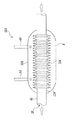
排気通路35は、上述の如く、排気マニフォルド40や排気管42などにより区画形成されている。ここでは、排気通路18を区画形成するそれら部材(排気通路画成部材)の内の排気管42に隣接して、容器150は設けられる。より具体的には、排気管42は容器150を貫通するようにして設けられている。このようなそれらの関係は、排気通路35と容器150内との間の熱交換を可能にする。つまり、排気通路35を流れる排気ガスの熱を用いて、容器150の内部を直接的に加熱することが可能である。排気通路35が貫通するようにして設けられた容器150周辺の一部断面模式図を図3に示す。   As described above, the exhaust passage 35 is defined by the exhaust manifold 40, the exhaust pipe 42, and the like. Here, the container 150 is provided adjacent to the exhaust pipe 42 among those members (exhaust passage defining members) that define the exhaust passage 18. More specifically, the exhaust pipe 42 is provided so as to penetrate the container 150. Such a relationship enables heat exchange between the exhaust passage 35 and the inside of the container 150. That is, the inside of the container 150 can be directly heated using the heat of the exhaust gas flowing through the exhaust passage 35. FIG. 3 shows a partial cross-sectional schematic view of the periphery of the container 150 provided so that the exhaust passage 35 penetrates.

容器150内の空間Sは、外壁102と、排気管42の一部でもある略円筒状の内壁104とにより区画形成されている。内壁104は、容器150内の排気ガスと、排気通路35を流れる排気ガスとの間の熱交換を促すべく、表面積が大きくなるように、波状あるいは蛇腹形状にされた波状部106を備えている。波状部106は熱交換手段を構成する。容器150内に位置付けられた排気管42の一部すなわち内壁104がこのような構造を有するので、排気通路35を流れる排気ガスの熱を容器150内の空間に取り込まれた排気ガスに的確に伝達することができる。すなわち、排気通路35を流れる排気ガスの熱を用いて、容器150の内部を加熱することができる。これにより、容器150内の気体の圧力および温度は上昇し得る。なお、波状部106は、内壁104に生じる内部熱応力を緩和する役目も担う。   A space S in the container 150 is defined by an outer wall 102 and a substantially cylindrical inner wall 104 that is also a part of the exhaust pipe 42. The inner wall 104 includes a corrugated portion 106 that has a corrugated or bellows shape so as to increase the surface area in order to promote heat exchange between the exhaust gas in the container 150 and the exhaust gas flowing through the exhaust passage 35. . The waved portion 106 constitutes a heat exchange means. Since a part of the exhaust pipe 42 positioned inside the container 150, that is, the inner wall 104 has such a structure, the heat of the exhaust gas flowing through the exhaust passage 35 is accurately transmitted to the exhaust gas taken into the space in the container 150. can do. That is, the inside of the container 150 can be heated using the heat of the exhaust gas flowing through the exhaust passage 35. Thereby, the pressure and temperature of the gas in the container 150 can rise. The wavy portion 106 also serves to relieve internal thermal stress generated on the inner wall 104.

なお、本第2実施形態の容器150には設けられていないが、容器150内の圧力が所定の上限圧、例えばゲージ圧で300kPaを超えるようになると、自動で開弁して、その圧力をその所定の上限圧以下に抑制する安全弁が設けられてもよい。安全弁は、容器150内に収容された排気ガスを上流側浄化部44および下流側浄化部46の両方を通過させてから排出させるように、構成されるのが望ましい。そのためには容器150の配置箇所は例えば上流側浄化部44上流側の排気通路画成部材と隣接して設けられるのがよい。   Although not provided in the container 150 of the second embodiment, when the pressure in the container 150 exceeds a predetermined upper limit pressure, for example, 300 kPa as a gauge pressure, the valve is automatically opened to reduce the pressure. A safety valve that suppresses the pressure to be equal to or lower than the predetermined upper limit pressure may be provided. The safety valve is preferably configured to exhaust the exhaust gas stored in the container 150 after passing through both the upstream side purification unit 44 and the downstream side purification unit 46. For this purpose, for example, the location of the container 150 is preferably provided adjacent to the exhaust passage defining member on the upstream side of the upstream purification unit 44.

以上、上記したような構成を容器150などが有するので、容器150内に回収および収容された排気ガスは加熱されて、その圧力は上昇し得る。したがって、容器150内の排気ガスの圧力は、上記第1実施形態の容器50内の排気ガスの圧力に比べて、より容易に且つ確実に排気通路E2の圧力よりも高くされる。そのため、容器150内の排気ガスの利用可能な期間が拡大するので、下流側浄化部46に容器150内の還元成分を含む排気ガスをより所望の時期に確実に供給することが可能になる。   As described above, since the container 150 or the like has the above-described configuration, the exhaust gas collected and stored in the container 150 can be heated to increase its pressure. Therefore, the pressure of the exhaust gas in the container 150 is more easily and surely made higher than the pressure of the exhaust passage E2 as compared with the pressure of the exhaust gas in the container 50 of the first embodiment. For this reason, the usable period of the exhaust gas in the container 150 is expanded, so that the exhaust gas containing the reducing component in the container 150 can be reliably supplied to the downstream side purification unit 46 at a desired time.

次に、本発明の第3実施形態について図4および図5に基づいて説明する。ただし、本第3実施形態は、上記第1実施形態と、主に、排気通路E2に排気絞り弁およびそのためのアクチュエータが設置されたことが異なる以外は概ね同じ構成を有する。そこで、ここでは上記第1実施形態で説明したのと同じ(あるいは対応する)構成要素に上記で用いたのと同じ符号を付してそれらの説明を省略し、以下では第1実施形態との相違点について説明する。なお、本第3実施形態でも、上記第1実施形態で説明したのと概ね同様の制御が行われ、且つ、同様の効果が奏されるが、この説明も大部分省略される。ただし、本第3実施形態は、上記第2実施形態と同様に排気通路を流れる排気ガスの熱で容器内の排気ガスを加熱する機構を備えてもよいが、本第3実施形態はそのような機構を備えない形態である。   Next, a third embodiment of the present invention will be described with reference to FIGS. However, the third embodiment has substantially the same configuration as the first embodiment except that an exhaust throttle valve and an actuator therefor are mainly installed in the exhaust passage E2. Therefore, here, the same (or corresponding) components as those described in the first embodiment are denoted by the same reference numerals as those used above, and the description thereof is omitted. Differences will be described. In the third embodiment, the same control as described in the first embodiment is performed and the same effect is obtained, but this description is largely omitted. However, the third embodiment may be provided with a mechanism for heating the exhaust gas in the container with the heat of the exhaust gas flowing through the exhaust passage, as in the second embodiment, but the third embodiment is not so. It is a form which does not have a simple mechanism.

本第3実施形態では、排気通路E2に排気絞り弁202が設けられている。排気絞り弁202は、上流側浄化部44と下流側浄化部46との間の排気通路E2であって、且つ、放出通路56のノズル64近傍に設けられている。より具体的には、図5の拡大模式図に示すように排気絞り弁202はノズル64の上流側近傍に設けられている。ここでは排気絞り弁202はバタフライ式弁であり、ECU70からの作動信号により作動制御されるアクチュエータ204により駆動される。図5では、排気絞り弁202が全開の開状態の開位置Iにあるところが点線で描かれていて、それが半開きの状態の半開位置IIにあるところが実線で描かれている。図5から明らかなように、半開状態IIにある排気絞り弁202の下流側開口部202dがノズル64の噴出口近傍に位置するように排気絞り弁202の弁体は位置付けられている。したがって、ノズル64の1つの噴出口が排気絞り弁202によって排気通路E2の縮小(縮径)され得る箇所(排気通路縮小部)の下流側近傍に位置される。なお、排気絞り弁202の開度を制御する排気絞り弁制御手段は、アクチュエータ204と、ECU70の一部とを含んで構成される。   In the third embodiment, an exhaust throttle valve 202 is provided in the exhaust passage E2. The exhaust throttle valve 202 is provided in the exhaust passage E <b> 2 between the upstream purification unit 44 and the downstream purification unit 46 and in the vicinity of the nozzle 64 of the discharge passage 56. More specifically, the exhaust throttle valve 202 is provided in the vicinity of the upstream side of the nozzle 64 as shown in the enlarged schematic view of FIG. Here, the exhaust throttle valve 202 is a butterfly valve, and is driven by an actuator 204 that is controlled by an operation signal from the ECU 70. In FIG. 5, the position where the exhaust throttle valve 202 is in the open position I in the fully open state is drawn with a dotted line, and the place where it is in the half open position II in the half opened state is drawn with a solid line. As is clear from FIG. 5, the valve body of the exhaust throttle valve 202 is positioned so that the downstream opening 202 d of the exhaust throttle valve 202 in the half-open state II is positioned in the vicinity of the jet outlet of the nozzle 64. Accordingly, one nozzle outlet of the nozzle 64 is positioned in the vicinity of the downstream side of the portion (exhaust passage reducing portion) where the exhaust passage E2 can be reduced (reduced diameter) by the exhaust throttle valve 202. The exhaust throttle valve control means for controlling the opening degree of the exhaust throttle valve 202 includes the actuator 204 and a part of the ECU 70.

排気絞り弁202は、通常は、開位置Iの開状態に保持されている。そして、排気通路E1から排気ガスを容器50内に回収するときに、半開位置IIに制御される。これにより、排気通路35の内、排気絞り弁202上流側の排気通路の圧力が高められ、より高い圧力の排気ガスが容器50内に回収されるようになる。ただし、加速運転時に容器50内への排気ガスの回収を行うときには車両に制動力が生じるのを防止するべく排気絞り弁202は閉弁されなくても良く、また、機関始動時に容器50内への排気ガスの回収を行うときには排気絞り弁202は全閉の閉状態にされても良い。なお、排気ガスの回収に際して排気絞り弁202を閉弁制御する場合には、その閉弁により排気通路E1の圧力が高められるので、容器50内の圧力が上記第1所定圧力以下のときに関わらず、排気ガスの回収は行われ得る。この場合には、容器50内の圧力を排気通路E1の圧力が上回ったとき回収弁52が開弁され得る。この判定のために、本第3実施形態では、さらに、排気絞り弁202上流側の排気通路、例えば排気通路E1の圧力を検出するための圧力センサ206が設けられている。   The exhaust throttle valve 202 is normally held in the open state at the open position I. And when exhaust gas is collect | recovered in the container 50 from the exhaust passage E1, it is controlled to the half-open position II. As a result, the pressure of the exhaust passage 35 upstream of the exhaust throttle valve 202 in the exhaust passage 35 is increased, and the exhaust gas having a higher pressure is recovered in the container 50. However, when collecting exhaust gas into the container 50 during acceleration operation, the exhaust throttle valve 202 does not have to be closed in order to prevent a braking force from being generated in the vehicle. When collecting the exhaust gas, the exhaust throttle valve 202 may be fully closed. Note that, when the exhaust throttle valve 202 is controlled to be closed when collecting the exhaust gas, the pressure in the exhaust passage E1 is increased by the closing of the exhaust throttle valve 202. Therefore, this is concerned when the pressure in the container 50 is lower than the first predetermined pressure. Instead, exhaust gas recovery may be performed. In this case, the recovery valve 52 may be opened when the pressure in the container 50 exceeds the pressure in the exhaust passage E1. For this determination, the third embodiment further includes a pressure sensor 206 for detecting the pressure in the exhaust passage upstream of the exhaust throttle valve 202, for example, the exhaust passage E1.

さらに、排気絞り弁202は、排気通路E2へ排気ガスを容器50内から放出するときに、半開位置IIに制御される。ただし、排気絞り弁202がここで半開位置にされているときは、放出弁60が開弁されているときに対応する。これにより、図5に模式的に排気通路E2の排気ガスの流れを示すように、排気絞り弁202により排気通路E2の流路は狭められるので、その下流側開口部202d下流側近傍では排気通路E2を流れる排気ガスの流速は高められると共にその圧力は低められる。したがって、ノズル64の1つの噴出口が排気通路E2に形成された排気通路縮小部の下流側近傍に位置されるので、容器50内の排気ガスを排気通路E2側へ吸引する力が放出通路56を流れる排気ガスに作用する。そして、このようにして容器50内から排気通路E2に至った排気ガスは排気絞り弁202を通った排気ガスと適切にミキシングされる。その結果、容器50内から供給された排気ガスすなわちHCやCOなどの還元成分を含む排気ガスは下流側浄化部46に満遍なく行き渡ることが可能になる。したがって、下流側浄化部46の全体でNOx吸蔵能をより確実に回復させることができるようになる。   Further, the exhaust throttle valve 202 is controlled to the half-open position II when exhaust gas is discharged from the container 50 into the exhaust passage E2. However, the case where the exhaust throttle valve 202 is in the half-open position corresponds to the case where the discharge valve 60 is opened. Accordingly, as schematically shown in FIG. 5, the flow of the exhaust gas in the exhaust passage E2 is narrowed by the exhaust throttle valve 202, so that the exhaust passage is near the downstream side of the downstream opening 202d. The flow rate of the exhaust gas flowing through E2 is increased and the pressure is decreased. Accordingly, since one jet port of the nozzle 64 is positioned in the vicinity of the downstream side of the exhaust passage reduction portion formed in the exhaust passage E2, the force for sucking the exhaust gas in the container 50 toward the exhaust passage E2 is increased. It acts on the exhaust gas flowing through. The exhaust gas that has thus reached the exhaust passage E2 from the container 50 is appropriately mixed with the exhaust gas that has passed through the exhaust throttle valve 202. As a result, the exhaust gas supplied from the inside of the container 50, that is, the exhaust gas containing a reducing component such as HC or CO, can be distributed evenly to the downstream purification unit 46. Therefore, the NOx occlusion ability can be recovered more reliably in the entire downstream purification unit 46.

次に、本発明の第4実施形態について図6に基づいて説明する。ただし、本第4実施形態は、上記第1実施形態と、放出通路56の排気通路E2側の端部の部材の構成が異なるが、他の構成は概ね同じである。そこで、ここでは上記第1実施形態で説明したのと同じ(あるいは対応する)構成要素に上記で用いたのと同じ符号を付してそれらの説明を省略し、本第4実施形態の放出通路56下流側の一部の部材の構成およびそれによる効果を図6の模式図に基づいて説明する。なお、本第4実施形態でも、上記第1実施形態で説明したのと同様の制御が行われ、且つ、同様の効果が奏されるが、この説明も省略される。ただし、本第4実施形態は、上記第2実施形態と同様に排気通路35を流れる排気ガスの熱で容器50内の排気ガスを加熱する機構を備えてもよいが、本第4実施形態はそのような機構を備えない形態である。また、本第4実施形態は、上記第3実施形態の如く、排気通路35の内、上流側浄化部44上流側の排気通路E1と回収通路47との連通箇所よりも下流側に設けられ得る排気絞り弁を備えてもよいが、本第4実施形態はそのような機構を備えない形態である。   Next, a fourth embodiment of the present invention will be described with reference to FIG. However, the fourth embodiment is different from the first embodiment in the configuration of the member at the end of the discharge passage 56 on the exhaust passage E2 side, but the other configurations are substantially the same. Therefore, here, the same (or corresponding) components as those described in the first embodiment are denoted by the same reference numerals as those used above, and their description is omitted, and the discharge passage of the fourth embodiment is omitted. The configuration of some of the members on the downstream side 56 and the effects thereof will be described with reference to the schematic diagram of FIG. In the fourth embodiment, the same control as described in the first embodiment is performed and the same effect is produced, but this description is also omitted. However, the fourth embodiment may include a mechanism for heating the exhaust gas in the container 50 with the heat of the exhaust gas flowing through the exhaust passage 35 as in the second embodiment, but the fourth embodiment It is a form without such a mechanism. Further, in the fourth embodiment, as in the third embodiment, the exhaust passage 35 may be provided on the downstream side of the communication portion between the exhaust passage E1 upstream of the upstream purification unit 44 and the recovery passage 47. Although an exhaust throttle valve may be provided, the fourth embodiment is a form in which such a mechanism is not provided.

図6に示すように、本第4実施形態の放出通路56下流側端部には複数の噴出口364hを有するスプレーバー364が設けられている。すなわち放出管58の排気通路E2側端部は排気通路E2へ延出され、その延出部に複数の噴出口364hが設けられているのと同じである。噴出口364hはいずれの方向に向けて設けられても良いが、ここでは図6では明瞭でないが上流側に向けて開口するように位置付けられている。これにより噴出口364hから排気通路E2へ噴射供給された排気ガスは、排気通路E2を流れてきた排気ガスと適切にミキシングされることになる。したがって、上記第3実施形態と同様に、容器50内から供給された排気ガスすなわちHCなどの還元成分を含む排気ガスは下流側浄化部46に満遍なく行き渡ることが可能になる。したがって、下流側浄化部46の全体でNOx吸蔵能をより確実に回復させることができるようになる。   As shown in FIG. 6, a spray bar 364 having a plurality of jet ports 364h is provided at the downstream end portion of the discharge passage 56 of the fourth embodiment. That is, the end of the discharge pipe 58 on the side of the exhaust passage E2 extends to the exhaust passage E2, and is the same as the plurality of jet ports 364h provided in the extended portion. The jet outlet 364h may be provided in any direction, but here, it is positioned so as to open toward the upstream side although it is not clear in FIG. As a result, the exhaust gas injected and supplied from the ejection port 364h to the exhaust passage E2 is appropriately mixed with the exhaust gas flowing through the exhaust passage E2. Therefore, similarly to the third embodiment, the exhaust gas supplied from the inside of the container 50, that is, the exhaust gas containing a reducing component such as HC, can reach the downstream purification unit 46 evenly. Therefore, the NOx occlusion ability can be recovered more reliably in the entire downstream purification unit 46.

以上、本発明を第1から第4実施形態に基づいて説明したが本発明はこれらに限定されない。例えば、下流側浄化部46は、NOx浄化能力を有する触媒であればよく、上記構成に限定されない。具体的には、下流側浄化部46は、選択還元型NOx触媒を含んで構成され得る。また、下流側浄化部のNOx吸蔵能の回復を図るタイミングは、運転状態から累積的に見積もられたNOx吸蔵量が所定量を超えたときとされても良い。   As mentioned above, although this invention was demonstrated based on 1st-4th embodiment, this invention is not limited to these. For example, the downstream purification unit 46 may be a catalyst having NOx purification capability, and is not limited to the above configuration. Specifically, the downstream purification unit 46 may be configured to include a selective reduction type NOx catalyst. Further, the timing for recovering the NOx occlusion capacity of the downstream purification unit may be when the NOx occlusion amount cumulatively estimated from the operating state exceeds a predetermined amount.

上記各種の実施形態では、回収弁52や放出弁60はポペット式弁であったがそれらはそれ以外の形式の弁であってもよく、バタフライ式弁、シャッター式弁であり得る。なお、回収弁52は、逆止弁によって代替され得る。また、排気絞り弁202はバタフライ式弁であったが、それ以外の形式の弁であってもよい。排気絞り弁202は、例えば、ポペット式弁、シャッター式弁であり得る。なお、排気絞り弁202として、排気ブレーキ用に設けられた弁が用いられてもよい。   In the various embodiments described above, the recovery valve 52 and the discharge valve 60 are poppet valves, but they may be other types of valves, and may be butterfly valves or shutter valves. Note that the recovery valve 52 can be replaced by a check valve. Further, although the exhaust throttle valve 202 is a butterfly valve, other types of valves may be used. The exhaust throttle valve 202 can be, for example, a poppet valve or a shutter valve. As the exhaust throttle valve 202, a valve provided for an exhaust brake may be used.

また、上記各種の実施形態では、容器50、150を1つ設けることにしたが、それは複数個設けられてもよい。そして容器50、150を2つ以上複数個設ける場合には、それらは車両に分散して配置され得る。   In the various embodiments described above, one container 50, 150 is provided, but a plurality of containers 50, 150 may be provided. When two or more containers 50 and 150 are provided, they can be distributed in the vehicle.

なお、上記各種の実施形態では、本発明をディーゼル機関に適用して説明したが、これに限定されず、本発明は、ポート噴射型式のガソリン機関、筒内噴射形式のガソリン機関等の各種の内燃機関に適用可能である。また、用いられる燃料は、軽油やガソリンに限らず、アルコール燃料、LPG(液化天然ガス)等でもよい。また、本発明が適用される内燃機関の気筒数などはいくつであってもよい。   In the various embodiments described above, the present invention is applied to a diesel engine. However, the present invention is not limited to this, and the present invention is not limited to a port injection type gasoline engine and a cylinder injection type gasoline engine. Applicable to internal combustion engines. The fuel used is not limited to light oil or gasoline, but may be alcohol fuel, LPG (liquefied natural gas), or the like. Further, the number of cylinders of the internal combustion engine to which the present invention is applied may be any number.

なお、上記第1から第4実施形態およびその変形例では本発明をある程度の具体性をもって説明したが、本発明については、特許請求の範囲に記載された発明の精神や範囲から離れることなしに、さまざまな改変や変更が可能であることは理解されなければならない。すなわち、本発明は特許請求の範囲およびその等価物の範囲および趣旨に含まれる修正および変更を包含するものである。   Although the present invention has been described with a certain degree of specificity in the first to fourth embodiments and the modifications thereof, the present invention is not deviated from the spirit and scope of the invention described in the claims. It should be understood that various modifications and changes are possible. That is, the present invention includes modifications and changes that fall within the scope and spirit of the appended claims and their equivalents.

第1実施形態の排気ガス浄化システムが適用された車両の内燃機関システムの概念図である。1 is a conceptual diagram of an internal combustion engine system for a vehicle to which an exhaust gas purification system of a first embodiment is applied. 第2実施形態の排気ガス浄化システムが適用された車両の内燃機関システムの概念図である。It is a conceptual diagram of the internal combustion engine system of the vehicle to which the exhaust gas purification system of 2nd Embodiment was applied. 図2の容器周辺を拡大して表した一部断面模式図である。It is a partial cross section schematic diagram which expanded and represented the container periphery of FIG. 第3実施形態の排気ガス浄化システムが適用された車両の内燃機関システムの概念図である。It is a conceptual diagram of the internal combustion engine system of the vehicle to which the exhaust gas purification system of 3rd Embodiment was applied. 図4の放出通路下流側端部近傍を拡大して表した断面模式図である。It is a cross-sectional schematic diagram which expanded and represented the discharge channel downstream edge part vicinity of FIG. 第4実施形態の放出通路下流側端部近傍を拡大して表した断面模式図である。It is the cross-sectional schematic diagram which expanded and represented the discharge channel downstream edge part vicinity of 4th Embodiment.

符号の説明Explanation of symbols

10 内燃機関
35 排気通路
44 上流側浄化部
46 下流側浄化部
47 回収通路
50、150 容器
56 放出通路
DESCRIPTION OF SYMBOLS 10 Internal combustion engine 35 Exhaust passage 44 Upstream side purification | cleaning part 46 Downstream side purification | cleaning part 47 Collection | recovery passages 50 and 150 Container 56 Release passage

Claims (6)

内燃機関の排気通路に直列的に配置された上流側浄化部および下流側浄化部を備え、該下流側浄化部がNOx浄化能力を有する触媒を含む、排気ガス浄化システムにおいて、
前記上流側浄化部上流側の排気通路に一端部が連通されると共に回収弁が設けられた回収通路と、
該回収通路の他端部が連通された排気ガス収容容器と、
該排気ガス収容容器に一端部が連通されると共に他端部が前記上流側浄化部および前記下流側浄化部の間の排気通路に連通されて放出弁が設けられた放出通路と、
前記排気ガス収容容器内の還元成分を含む排気ガスを放出するべく前記放出弁を開弁制御する放出弁制御手段と
を備えることを特徴とする排気ガス浄化システム。
In an exhaust gas purification system comprising an upstream purification unit and a downstream purification unit arranged in series in an exhaust passage of an internal combustion engine, the downstream purification unit including a catalyst having NOx purification capability,
A recovery passage having one end communicated with the exhaust passage on the upstream side of the upstream purification section and provided with a recovery valve;
An exhaust gas container in which the other end of the recovery passage is communicated;
A discharge passage in which one end portion is communicated with the exhaust gas storage container and the other end portion is communicated with an exhaust passage between the upstream purification portion and the downstream purification portion, and a discharge valve is provided;
An exhaust gas purification system comprising: a release valve control means for controlling the opening of the release valve to release exhaust gas containing a reducing component in the exhaust gas storage container.
前記上流側浄化部は、酸化能力あるいはPM捕集機能を有するように構成されていることを特徴とする請求項1に記載の排気ガス浄化システム。   The exhaust gas purification system according to claim 1, wherein the upstream purification unit is configured to have an oxidation capability or a PM trapping function. 前記回収通路に設けられた前記回収弁の開度を制御する回収弁制御手段をさらに備え、
該回収弁制御手段は、機関始動時あるいは加速運転時に、前記回収弁を開弁制御することを特徴とする請求項1あるいは2に記載の排気ガス浄化システム。
A recovery valve control means for controlling the opening of the recovery valve provided in the recovery passage;
The exhaust gas purification system according to claim 1 or 2, wherein the recovery valve control means controls the recovery valve to open when the engine is started or accelerated.
前記内燃機関の排気通路の内、前記上流側浄化部上流側の排気通路と前記回収通路との連通箇所よりも下流側に設けられた排気絞り弁と、
該排気絞り弁の開度を制御する排気絞り弁制御手段と
をさらに備え、
該排気絞り弁制御手段は、機関始動時に、前記排気絞り弁を閉弁制御することを特徴とする請求項1から3のいずれかに記載の排気ガス浄化システム。
Among the exhaust passages of the internal combustion engine, an exhaust throttle valve provided on the downstream side of the communication portion between the exhaust passage upstream of the upstream purification unit and the recovery passage;
Exhaust throttle valve control means for controlling the opening of the exhaust throttle valve,
4. The exhaust gas purification system according to claim 1, wherein the exhaust throttle valve control means controls the exhaust throttle valve to be closed when the engine is started.
前記放出通路の排気通路側の前記他端部に1つあるいは複数の噴出口が設けられていることを特徴とする請求項1から4のいずれかに記載の排気ガス浄化システム。   The exhaust gas purification system according to any one of claims 1 to 4, wherein one or a plurality of jet outlets are provided at the other end portion of the discharge passage on the exhaust passage side. 前記噴出口は、前記上流側浄化部および前記下流側浄化部の間の前記排気通路に形成される排気通路縮小部近傍に位置されることを特徴とする請求項5に記載の排気ガス浄化システム。   6. The exhaust gas purification system according to claim 5, wherein the jet port is located in the vicinity of an exhaust passage reduction portion formed in the exhaust passage between the upstream purification unit and the downstream purification unit. .
JP2007205772A 2007-08-07 2007-08-07 Exhaust emission control device Withdrawn JP2009041406A (en)

Priority Applications (1)

Application Number Priority Date Filing Date Title
JP2007205772A JP2009041406A (en) 2007-08-07 2007-08-07 Exhaust emission control device

Applications Claiming Priority (1)

Application Number Priority Date Filing Date Title
JP2007205772A JP2009041406A (en) 2007-08-07 2007-08-07 Exhaust emission control device

Publications (1)

Publication Number Publication Date
JP2009041406A true JP2009041406A (en) 2009-02-26

Family

ID=40442415

Family Applications (1)

Application Number Title Priority Date Filing Date
JP2007205772A Withdrawn JP2009041406A (en) 2007-08-07 2007-08-07 Exhaust emission control device

Country Status (1)

Country Link
JP (1) JP2009041406A (en)

Similar Documents

Publication Publication Date Title
EP2185796B1 (en) Exhaust gas purification apparatus for internal combustion engine and method of controlling the same
EP2172627A1 (en) Exhaust purification apparatus
EP2808508B1 (en) Control device for internal combustion engine
JP2007154772A (en) Control device for internal combustion engine
JP5120503B2 (en) Internal combustion engine
EP3039259B9 (en) Exhaust purification system for an internal combustion engine
EP2985431B1 (en) Exhaust purification device of internal combustion engine
EP2993324B1 (en) Exhaust purification device for internal combustion engine
JP2007071142A (en) Exhaust emission control system for internal combustion engine
EP2460996B1 (en) Exhaust emission purifier of internal combustion engine
CN112211697B (en) Control device for internal combustion engine
JP2010043583A (en) Exhaust emission purifier of internal combustion engine
JP2009041435A (en) Secondary air supply device in internal combustion engine
JP2009041406A (en) Exhaust emission control device
JP5428633B2 (en) Internal combustion engine
JP4084289B2 (en) Exhaust purification device
JP2010150978A (en) Exhaust emission control device
JP2009138605A (en) Deterioration diagnosing device of nox catalyst
JP3557930B2 (en) Exhaust gas purification device for internal combustion engine
JP2007138924A (en) Exhaust emission control device of internal combustion engine
JP2007023807A (en) Exhaust emission control device for engine
EP3036412B1 (en) Exhaust purification system of internal combustion engine
WO2011114381A1 (en) Exhaust gas evacuation device for internal combustion engine
US9926826B2 (en) Internal combustion engine
JP2008255890A (en) Exhaust emission control device of internal combustion engine

Legal Events

Date Code Title Description
A621 Written request for application examination

Free format text: JAPANESE INTERMEDIATE CODE: A621

Effective date: 20100118

A761 Written withdrawal of application

Free format text: JAPANESE INTERMEDIATE CODE: A761

Effective date: 20110322