JP2009031870A - Image processing for estimation of photographic object distance - Google Patents
Image processing for estimation of photographic object distance Download PDFInfo
- Publication number
- JP2009031870A JP2009031870A JP2007192459A JP2007192459A JP2009031870A JP 2009031870 A JP2009031870 A JP 2009031870A JP 2007192459 A JP2007192459 A JP 2007192459A JP 2007192459 A JP2007192459 A JP 2007192459A JP 2009031870 A JP2009031870 A JP 2009031870A
- Authority
- JP
- Japan
- Prior art keywords
- image
- deformation
- subject
- area
- unit
- Prior art date
- Legal status (The legal status is an assumption and is not a legal conclusion. Google has not performed a legal analysis and makes no representation as to the accuracy of the status listed.)
- Pending
Links
- 238000012545 processing Methods 0.000 title claims description 179
- 238000003384 imaging method Methods 0.000 claims abstract description 78
- 238000000034 method Methods 0.000 claims description 174
- 230000008569 process Effects 0.000 claims description 125
- 238000001514 detection method Methods 0.000 claims description 43
- 238000004590 computer program Methods 0.000 claims description 10
- 230000007423 decrease Effects 0.000 claims description 8
- 238000003672 processing method Methods 0.000 claims description 7
- 238000011156 evaluation Methods 0.000 description 152
- 238000012937 correction Methods 0.000 description 65
- 238000007639 printing Methods 0.000 description 37
- 238000010586 diagram Methods 0.000 description 33
- 238000004364 calculation method Methods 0.000 description 18
- 230000009466 transformation Effects 0.000 description 15
- 230000006870 function Effects 0.000 description 14
- 238000004904 shortening Methods 0.000 description 13
- 230000004048 modification Effects 0.000 description 12
- 238000012986 modification Methods 0.000 description 12
- 238000009826 distribution Methods 0.000 description 10
- 238000002360 preparation method Methods 0.000 description 10
- 230000005484 gravity Effects 0.000 description 8
- 210000004709 eyebrow Anatomy 0.000 description 7
- 230000007717 exclusion Effects 0.000 description 6
- 235000002673 Dioscorea communis Nutrition 0.000 description 5
- 241000544230 Dioscorea communis Species 0.000 description 5
- 208000035753 Periorbital contusion Diseases 0.000 description 5
- 239000011159 matrix material Substances 0.000 description 4
- 239000013256 coordination polymer Substances 0.000 description 3
- 210000004209 hair Anatomy 0.000 description 3
- 238000006243 chemical reaction Methods 0.000 description 2
- 239000006185 dispersion Substances 0.000 description 2
- 239000004973 liquid crystal related substance Substances 0.000 description 2
- 230000007246 mechanism Effects 0.000 description 2
- 238000003860 storage Methods 0.000 description 2
- 238000000844 transformation Methods 0.000 description 2
- 208000029152 Small face Diseases 0.000 description 1
- 230000008901 benefit Effects 0.000 description 1
- 230000008859 change Effects 0.000 description 1
- 238000004891 communication Methods 0.000 description 1
- 230000006835 compression Effects 0.000 description 1
- 238000007906 compression Methods 0.000 description 1
- 238000010017 direct printing Methods 0.000 description 1
- 230000002349 favourable effect Effects 0.000 description 1
- 210000001061 forehead Anatomy 0.000 description 1
- 230000012447 hatching Effects 0.000 description 1
- 210000003128 head Anatomy 0.000 description 1
- 238000004519 manufacturing process Methods 0.000 description 1
- 210000000056 organ Anatomy 0.000 description 1
- 230000009467 reduction Effects 0.000 description 1
- 238000010187 selection method Methods 0.000 description 1
- 238000000859 sublimation Methods 0.000 description 1
- 230000008022 sublimation Effects 0.000 description 1
Images


Classifications
-
- G06T5/70—
-
- G—PHYSICS
- G06—COMPUTING; CALCULATING OR COUNTING
- G06T—IMAGE DATA PROCESSING OR GENERATION, IN GENERAL
- G06T7/00—Image analysis
- G06T7/10—Segmentation; Edge detection
- G06T7/194—Segmentation; Edge detection involving foreground-background segmentation
-
- G—PHYSICS
- G06—COMPUTING; CALCULATING OR COUNTING
- G06V—IMAGE OR VIDEO RECOGNITION OR UNDERSTANDING
- G06V40/00—Recognition of biometric, human-related or animal-related patterns in image or video data
- G06V40/10—Human or animal bodies, e.g. vehicle occupants or pedestrians; Body parts, e.g. hands
- G06V40/16—Human faces, e.g. facial parts, sketches or expressions
- G06V40/161—Detection; Localisation; Normalisation
-
- G—PHYSICS
- G06—COMPUTING; CALCULATING OR COUNTING
- G06T—IMAGE DATA PROCESSING OR GENERATION, IN GENERAL
- G06T2200/00—Indexing scheme for image data processing or generation, in general
- G06T2200/24—Indexing scheme for image data processing or generation, in general involving graphical user interfaces [GUIs]
Abstract
Description
本発明は、被写体距離を推定するための画像処理技術に関する。 The present invention relates to an image processing technique for estimating a subject distance.
デジタル画像を対象に、画像を変形するための画像処理技術が知られている(例えば特許文献1)。特許文献1には、顔の画像上の一部の領域(頬の画像を表す領域)を補正領域として設定し、補正領域を所定のパターンに従い複数の小領域に分割し、小領域毎に設定された倍率で画像を拡大または縮小することにより、顔の形状を変形する画像処理が開示されている。
An image processing technique for deforming an image for a digital image is known (for example, Patent Document 1). In
ところで、撮像装置(例えばデジタルスチルカメラ)による撮像によって生成された顔の画像を観察して得られる印象は、撮像時における撮像装置から被写体としての顔までの距離(以下「被写体距離」とも呼ぶ)に応じて変化しうる。そのため、顔の形状を変形する画像処理は、被写体距離に応じた態様で行われることが好ましい。しかし、画像の被写体距離を推定する方法は知られていなかった。 By the way, an impression obtained by observing a face image generated by imaging by an imaging device (for example, a digital still camera) is a distance from the imaging device to a face as a subject at the time of imaging (hereinafter also referred to as “subject distance”). Can vary depending on Therefore, it is preferable that the image processing for deforming the face shape is performed in a manner corresponding to the subject distance. However, a method for estimating the subject distance of the image has not been known.
なお、このような問題は、被写体が顔である場合に限らず、被写体が他の物である場合にも共通する問題であった。 Such a problem is not limited to the case where the subject is a face, but is a common problem when the subject is another object.
本発明は、上述した課題を解決するためになされたものであり、画像の被写体距離を推定する技術を提供することを目的とする。 SUMMARY An advantage of some aspects of the invention is to provide a technique for estimating the subject distance of an image.
上記課題の少なくとも一部を解決するために、本発明は、以下の形態または適用例として実現することが可能である。 In order to solve at least a part of the above problems, the present invention can be realized as the following forms or application examples.
[適用例1]画像処理装置であって、
撮像によって生成された対象画像の大きさに対する前記対象画像中の特定種類の被写体の画像の大きさを示す第1の情報を取得する第1の情報取得部と、
前記特定種類の被写体の大きさを示す第2の情報を取得する第2の情報取得部と、
前記対象画像の画角を特定可能な第3の情報を取得する第3の情報取得部と、
前記第1の情報と前記第2の情報と前記第3の情報とに基づき、前記対象画像生成時の撮像装置から前記特定種類の被写体までの距離である被写体距離を推定する被写体距離推定部と、を備える、画像処理装置。
Application Example 1 An image processing apparatus,
A first information acquisition unit that acquires first information indicating a size of an image of a specific type of subject in the target image with respect to a size of the target image generated by imaging;
A second information acquisition unit that acquires second information indicating the size of the subject of the specific type;
A third information acquisition unit that acquires third information capable of specifying the angle of view of the target image;
A subject distance estimation unit that estimates a subject distance, which is a distance from the imaging device when the target image is generated to the specific type of subject, based on the first information, the second information, and the third information; An image processing apparatus.
この画像処理装置では、第1の情報と第2の情報とに基づき、対象画像全体に対応した被写体の大きさを推定することができる。また、推定された対象画像全体に対応した被写体の大きさと第3の情報とに基づき、対象画像の被写体距離を推定することができる。 In this image processing apparatus, the size of the subject corresponding to the entire target image can be estimated based on the first information and the second information. Further, the subject distance of the target image can be estimated based on the size of the subject corresponding to the entire estimated target image and the third information.
[適用例2]請求項1記載の画像処理装置であって、さらに、
前記推定された被写体距離を用いて特定の処理を実行する特定処理実行部を備える、画像処理装置。
Application Example 2 The image processing apparatus according to
An image processing apparatus comprising: a specific process execution unit that executes a specific process using the estimated subject distance.
この画像処理装置では、推定された被写体距離を用いて特定の処理を実行することができる。 In this image processing apparatus, specific processing can be executed using the estimated subject distance.
[適用例3]請求項2記載の画像処理装置であって、
前記特定処理実行部は、
前記特定の処理として、前記対象画像における前記特定種類の被写体の画像を含む領域内の画像変形を行う変形処理部と、
前記推定された被写体距離に基づき、前記画像変形における変形の度合いを、前記被写体距離が小さいほど変形の度合いが大きくなるように設定する変形量設定部と、を含む、画像処理装置。
Application Example 3 In the image processing apparatus according to
The specific process execution unit
As the specific processing, a deformation processing unit that performs image deformation in an area including the image of the specific type of subject in the target image;
An image processing apparatus comprising: a deformation amount setting unit configured to set a degree of deformation in the image deformation based on the estimated subject distance so that the degree of deformation increases as the subject distance decreases.
この画像処理装置では、推定された被写体距離に合わせて画像を適切に変形させることができ、画像の観察によって得られる被写体の印象を、実物の観察によって得られる印象に近づけることができる。 In this image processing apparatus, the image can be appropriately deformed in accordance with the estimated subject distance, and the impression of the subject obtained by observing the image can be brought close to the impression obtained by observing the real object.
[適用例4]請求項2記載の画像処理装置であって、
前記特定処理実行部は、
前記特定の処理として、前記対象画像における所定の背景領域内の画像のぼかし処理を行うぼかし処理部と、
前記推定された被写体距離に基づき、前記ぼかし処理におけるぼかしの度合いを、前記被写体距離が小さいほどぼかしの度合いが大きくなるように設定するぼかし度合い設定部と、を含む、画像処理装置。
Application Example 4 In the image processing apparatus according to
The specific process execution unit
As the specific processing, a blur processing unit that performs a blur processing of an image in a predetermined background area in the target image;
An image processing apparatus, comprising: a blurring degree setting unit that sets a blurring degree in the blurring process based on the estimated subject distance so that the blurring degree increases as the subject distance decreases.
この画像処理装置では、推定された被写体距離に合わせた画像のぼかし処理を行うことができ、撮像装置の特性に適合した自然で好ましい画像のぼかし処理を実現することができる。 In this image processing apparatus, it is possible to perform an image blurring process in accordance with the estimated subject distance, and it is possible to realize a natural and preferable image blurring process suitable for the characteristics of the imaging apparatus.
[適用例5]請求項2記載の画像処理装置であって、
前記特定処理実行部は、
前記特定の処理として、前記特定種類の被写体を含む画像を表すデータと前記推定された被写体距離を示すデータとを含む画像ファイルの生成を行う画像ファイル生成部を含む、画像処理装置。
Application Example 5 In the image processing apparatus according to
The specific process execution unit
An image processing apparatus, comprising: an image file generation unit configured to generate an image file including data representing an image including the specific type of subject and data indicating the estimated subject distance as the specific processing.
この画像処理装置では、特定種類の被写体を含む画像を表すデータと推定された被写体距離を示すデータとを含む画像ファイルを生成することができる。 In this image processing apparatus, an image file including data representing an image including a specific type of subject and data representing the estimated subject distance can be generated.
[適用例6]請求項2記載の画像処理装置であって、さらに、
撮像により画像を生成する画像生成部を備え、
前記特定処理実行部は、
前記推定された被写体距離に基づき、前記特定の処理として、前記画像生成部による前記特定種類の被写体の撮像時に焦点の位置すべき範囲を、焦点が位置することが可能な最大の範囲よりも狭い範囲として設定する焦点範囲設定部を含む、画像処理装置。
Application Example 6 The image processing apparatus according to
An image generation unit that generates an image by imaging,
The specific process execution unit
Based on the estimated subject distance, as the specific processing, a range where the focus should be positioned when the image generation unit captures the specific type of subject is narrower than a maximum range where the focus can be positioned. An image processing apparatus including a focal range setting unit for setting as a range.
この画像処理装置では、焦点合わせに要する時間の短縮を図ることができる。 With this image processing apparatus, it is possible to reduce the time required for focusing.
[適用例7]請求項2記載の画像処理装置であって、さらに、
撮像により画像を生成する画像生成部を備え、
前記特定処理実行部は、
前記推定された被写体距離に基づき、前記特定の処理として、前記画像生成部による前記特定種類の被写体の撮像タイミングの決定を行うタイミング決定部を含む、画像処理装置。
Application Example 7 The image processing apparatus according to
An image generation unit that generates an image by imaging,
The specific process execution unit
An image processing apparatus comprising: a timing determining unit that determines the imaging timing of the specific type of subject by the image generation unit as the specific processing based on the estimated subject distance.
この画像処理装置では、被写体距離に関する撮像タイミングを定めて画像の生成を行うことができる。 In this image processing apparatus, it is possible to generate an image by determining an imaging timing related to the subject distance.
[適用例8]請求項1ないし請求項7のいずれかに記載の画像処理装置であって、さらに、
前記対象画像中における前記特定種類の被写体の画像を検出する被写体検出部を備える、画像処理装置。
Application Example 8 The image processing apparatus according to any one of
An image processing apparatus comprising: a subject detection unit that detects an image of the specific type of subject in the target image.
この画像処理装置では、対象画像から検出された特定種類の被写体について被写体距離を推定することができる。 In this image processing apparatus, the subject distance can be estimated for a specific type of subject detected from the target image.
[適用例9]請求項1ないし請求項8のいずれかに記載の画像処理装置であって、
前記特定種類の被写体は、人物の顔である、画像処理装置。
Application Example 9 An image processing apparatus according to any one of
The image processing apparatus, wherein the specific type of subject is a human face.
この画像処理装置では、被写体としての人物の顔について被写体距離を推定することができる。 In this image processing apparatus, the subject distance can be estimated for the face of a person as a subject.
[適用例10]請求項1ないし請求項9のいずれかに記載の画像処理装置であって、
前記第3の情報は、撮像時のレンズの焦点距離と結像面の大きさとの関係を特定する情報である、画像処理装置。
Application Example 10 An image processing apparatus according to any one of
The third information is an image processing apparatus that specifies a relationship between a focal length of a lens at the time of imaging and a size of an imaging plane.
なお、本発明は、種々の態様で実現することが可能であり、例えば、画像処理方法および装置、画像変形方法および装置、画像生成方法および装置、印刷方法および装置、これらの方法または装置の機能を実現するためのコンピュータプログラム、そのコンピュータプログラムを記録した記録媒体、そのコンピュータプログラムを含み搬送波内に具現化されたデータ信号、等の形態で実現することができる。 Note that the present invention can be realized in various modes. For example, an image processing method and apparatus, an image deformation method and apparatus, an image generation method and apparatus, a printing method and apparatus, and functions of these methods or apparatuses. Can be realized in the form of a computer program for realizing the above, a recording medium storing the computer program, a data signal including the computer program and embodied in a carrier wave, and the like.
次に、本発明の実施の形態を実施例に基づいて以下の順序で説明する。
A.第1実施例:
A−1.画像処理装置の構成:
A−2.顔形状補正印刷処理:
A−3.変形領域の設定:
A−4.変形処理:
A−5.他の変形処理:
B.第2実施例:
C.第3実施例:
D.変形例:
Next, embodiments of the present invention will be described in the following order based on examples.
A. First embodiment:
A-1. Configuration of image processing device:
A-2. Face shape correction printing process:
A-3. Deformation area settings:
A-4. Transformation process:
A-5. Other transformations:
B. Second embodiment:
C. Third embodiment:
D. Variations:
A.第1実施例:
A−1.画像処理装置の構成:
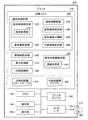
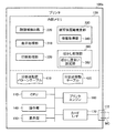
図1は、本発明の第1実施例における画像処理装置としてのプリンタ100の構成を概略的に示す説明図である。第1実施例のプリンタ100は、メモリカードMC等から取得した画像データに基づき画像を印刷する、いわゆるダイレクトプリントに対応したカラーインクジェットプリンタである。プリンタ100は、プリンタ100の各部を制御するCPU110と、例えばROMやRAMによって構成された内部メモリ120と、ボタンやタッチパネルにより構成された操作部140と、液晶ディスプレイにより構成された表示部150と、プリンタエンジン160と、カードインターフェース(カードI/F)170と、を備えている。プリンタ100は、さらに、他の機器(例えばデジタルスチルカメラやパーソナルコンピュータ)とのデータ通信を行うためのインターフェースを備えているとしてもよい。プリンタ100の各構成要素は、バスを介して互いに接続されている。
A. First embodiment:
A-1. Configuration of image processing device:
FIG. 1 is an explanatory diagram schematically showing the configuration of a
プリンタエンジン160は、印刷データに基づき印刷を行う印刷機構である。カードインターフェース170は、カードスロット172に挿入されたメモリカードMCとの間でデータのやり取りを行うためのインターフェースである。なお、本実施例では、メモリカードMCにRGBデータとしての画像データを含む画像ファイルが格納されている。この画像ファイルは、例えばデジタルスチルカメラ等の撮像装置によりExif(Exchangeable Image File Format)規格に則って生成されたファイルであり、撮像により生成された画像データの他に、撮像時の絞り・シャッタースピード・レンズの焦点距離等の付加データを含んでいる。プリンタ100は、カードインターフェース170を介してメモリカードMCに格納された画像ファイルの取得を行う。
The
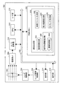
内部メモリ120には、顔形状補正部200と、顔領域検出部220と、被写体距離推定部330と、表示処理部310と、印刷処理部320とが格納されている。顔形状補正部200と顔領域検出部220と被写体距離推定部330とは、所定のオペレーティングシステムの下で、それぞれ後述する顔形状補正処理、顔領域検出処理、被写体距離推定処理を実行するためのコンピュータプログラムである。表示処理部310は、表示部150を制御して、表示部150上に処理メニューやメッセージを表示させるディスプレイドライバである。印刷処理部320は、画像データから印刷データを生成し、プリンタエンジン160を制御して、印刷データに基づく画像の印刷を実行するためのコンピュータプログラムである。CPU110は、内部メモリ120から、これらのプログラムを読み出して実行することにより、これら各部の機能を実現する。
The
顔形状補正部200は、プログラムモジュールとして、変形態様設定部210と、顔領域調整部230と、変形領域設定部240と、変形領域分割部250と、分割領域変形部260と、変形量設定部290と、を含んでいる。変形態様設定部210は、指定取得部212を含んでいる。また、被写体距離推定部330は、プログラムモジュールとして、情報取得部340を含んでいる。これらの各部の機能については、後述の顔形状補正印刷処理の説明において詳述する。なお、後述するように、変形領域分割部250と、分割領域変形部260と、により画像の変形が行われる。そのため、変形領域分割部250と分割領域変形部260とは、併せて「変形処理部」とも呼ぶことができる。また、顔領域検出部220は、被写体としての顔の画像を検出するものであり、「被写体検出部」とも呼ぶことができる。
The face
内部メモリ120には、また、分割点配置パターンテーブル410と分割点移動テーブル420とが格納されている。分割点配置パターンテーブル410および分割点移動テーブル420の内容についても、後述の顔形状補正印刷処理の説明において詳述する。
The
A−2.顔形状補正印刷処理:
プリンタ100は、メモリカードMCに格納された画像ファイルに基づき、画像の印刷を行う。カードスロット172にメモリカードMCが挿入されると、表示処理部310により、メモリカードMCに格納された画像の一覧表示を含むユーザインターフェースが表示部150に表示される。図2は、画像の一覧表示を含むユーザインターフェースの一例を示す説明図である。図2に示すユーザインターフェースには、8つのサムネイル画像TN1〜TN8と、5つのボタンBN1〜BN5が表示されている。なお、本実施例では、画像の一覧表示は、メモリカードMCに格納された画像ファイルに含まれるサムネイル画像を用いて実現される。
A-2. Face shape correction printing process:
The
第1実施例のプリンタ100は、図2に示すユーザインターフェースにおいて、ユーザにより、1つ(または複数)の画像が選択されると共に通常印刷ボタンBN3が選択されると、選択された画像を通常通り印刷する通常印刷処理を実行する。他方、当該ユーザインターフェースにおいて、ユーザにより、1つ(または複数)の画像が選択されると共に顔形状補正印刷ボタンBN4が選択されると、プリンタ100は、選択された画像について、画像中の顔の形状を補正して補正後の画像を印刷する顔形状補正印刷処理を実行する。図2の例では、サムネイル画像TN1と顔形状補正印刷ボタンBN4とが選択されているため、プリンタ100は、サムネイル画像TN1に対応する画像について顔形状補正印刷処理を行う。
In the
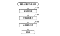
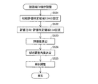
図3は、第1実施例のプリンタ100による顔形状補正印刷処理の流れを示すフローチャートである。ステップS100では、顔形状補正部200(図1)が、顔形状補正処理を実行する。本実施例の顔形状補正処理は、画像中の顔の少なくとも一部の形状(例えば顔の輪郭形状や目の形状)を補正する処理である。なお、目や鼻などの顔の一部分は、一般に器官とも呼ばれる。
FIG. 3 is a flowchart illustrating a flow of face shape correction printing processing by the
図4は、第1実施例における顔形状補正処理(図3のステップS100)の流れを示すフローチャートである。ステップS110では、顔形状補正部200(図1)が、顔形状補正処理の対象となる対象画像TIを設定する。顔形状補正部200は、図2に示したユーザインターフェースにおいてユーザにより選択されたサムネイル画像TN1に対応する画像を対象画像TIとして設定する。設定された対象画像TIの画像ファイルは、メモリカードMCからカードインターフェース170を介してプリンタ100に取得され、内部メモリ120の所定領域に格納される。なお、以下では、このようにメモリカードMCから取得され、プリンタ100の内部メモリ120に格納された画像ファイルに含まれる画像データを「元画像データ」とも呼ぶ。また、元画像データにより表される画像を「元画像」とも呼ぶ。
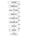
FIG. 4 is a flowchart showing the flow of the face shape correction process (step S100 in FIG. 3) in the first embodiment. In step S110, the face shape correction unit 200 (FIG. 1) sets a target image TI that is a target of face shape correction processing. The face
ステップS120(図4)では、変形態様設定部210(図1)が、顔形状補正のための画像変形のタイプと画像変形の度合いとを設定する。変形態様設定部210は、画像変形のタイプおよび度合いを設定するためのユーザインターフェースを表示部150に表示するように表示処理部310に指示し、当該ユーザインターフェースを通じてユーザにより指定された画像変形のタイプおよび度合いを選択し、処理に使用する画像変形タイプおよび度合いとして設定する。
In step S120 (FIG. 4), the deformation mode setting unit 210 (FIG. 1) sets the type of image deformation and the degree of image deformation for face shape correction. The deformation mode setting unit 210 instructs the
図5は、画像変形のタイプおよび度合いを設定するためのユーザインターフェースの一例を示す説明図である。図5に示すように、このユーザインターフェースには、画像変形タイプを設定するためのインターフェースが含まれている。本実施例では、例えば、顔の形状をシャープにする変形タイプ「タイプA」や、目の形状を大きくする変形タイプ「タイプB」等が選択肢として予め設定されているものとする。ユーザは、このインターフェースを介して画像変形のタイプを指定する。変形態様設定部210は、ユーザにより指定された画像変形タイプを、実際の処理に使用する画像変形タイプとして設定する。 FIG. 5 is an explanatory diagram showing an example of a user interface for setting the type and degree of image deformation. As shown in FIG. 5, this user interface includes an interface for setting an image deformation type. In this embodiment, for example, a deformation type “type A” that sharpens the shape of the face, a deformation type “type B” that increases the shape of the eyes, and the like are set in advance as options. The user specifies the type of image deformation via this interface. The deformation mode setting unit 210 sets the image deformation type designated by the user as the image deformation type used for actual processing.
また、図5に示すユーザインターフェースには、画像変形の度合い(程度)を設定するためのインターフェースが含まれている。図5に示すように、本実施例では、画像変形の度合いとして、強(S)、中(M)、弱(W)の3段階と、自動と、の4つが選択肢として予め設定されているものとする。ユーザは、このインターフェースを介して画像変形の度合いを指定する。強、中、弱の3つの内のいずれかが指定された場合には、変形態様設定部210は、指定された画像変形の度合いを、実際の処理に使用する画像変形の度合いとして設定する。「自動」が指定された場合には、後述するように、画像変形の度合い(変形量)が変形量設定部290(図1)によって自動的に設定される。ユーザインターフェースに設けられたチェックボックスは、ユーザが変形態様の詳細指定を希望する場合にチェックされる。 The user interface shown in FIG. 5 includes an interface for setting the degree (degree) of image deformation. As shown in FIG. 5, in this embodiment, the degree of image deformation is preset as three options of three levels of strong (S), medium (M), and weak (W), and automatic. Shall. The user designates the degree of image deformation via this interface. When one of the three of strong, medium, and weak is designated, the deformation mode setting unit 210 sets the designated degree of image deformation as the degree of image deformation used for actual processing. When “automatic” is designated, the degree of image deformation (deformation amount) is automatically set by the deformation amount setting unit 290 (FIG. 1), as will be described later. A check box provided in the user interface is checked when the user desires detailed designation of a deformation mode.
以降では、画像変形のタイプとして顔の形状をシャープにするための変形タイプ「タイプA」が設定され、画像変形の度合いとして「自動」が選択され、ユーザによる詳細指定の希望はなかったものとして説明を行う。 Hereinafter, it is assumed that the deformation type “type A” for sharpening the shape of the face is set as the image deformation type, “automatic” is selected as the degree of image deformation, and there is no desire for detailed designation by the user. Give an explanation.
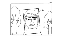
ステップS130(図4)では、顔領域検出部220(図1)が、対象画像TIにおける顔領域FAの検出を行う。ここで、顔領域FAとは、対象画像TI上の画像領域であって、少なくとも顔の一部の画像が含まれる領域を意味している。顔領域検出部220による顔領域FAの検出は、例えばテンプレートを利用したパターンマッチングによる方法(特開2004−318204参照)といった公知の顔検出方法を用いて実行される。
In step S130 (FIG. 4), the face area detection unit 220 (FIG. 1) detects the face area FA in the target image TI. Here, the face area FA is an image area on the target image TI and means an area including at least a partial image of the face. The detection of the face area FA by the face
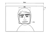
図6は、顔領域FAの検出結果の一例を示す説明図である。図6の例では、対象画像TIに人物の顔の画像が含まれている。そのため、ステップS130において、対象画像TIから顔領域FAが検出される。この顔領域FAは、図6に示すように、両目と鼻と口の画像を含む矩形の領域となっている。なお、顔領域検出部220は、顔領域FAの検出結果として、対象画像TIにおける顔領域FAの位置を特定可能な情報(例えば顔領域FAの4つの頂点の座標)を出力する。また、図6に示すように、本実施例では、対象画像TIの幅をWwi(単位は画素数)と表し、顔領域FAの幅をWfi(単位は画素数)と表すものとする。
FIG. 6 is an explanatory diagram showing an example of the detection result of the face area FA. In the example of FIG. 6, the target image TI includes a human face image. Therefore, in step S130, the face area FA is detected from the target image TI. The face area FA is a rectangular area including images of both eyes, nose and mouth as shown in FIG. Note that the face
なお、ステップS130の顔領域FAの検出において、顔領域FAが検出されなかった場合には、その旨が表示部150を通じてユーザに通知される。この場合には、顔形状補正を伴わない通常印刷が行われるとしてもよいし、他の顔検出方法を用いた顔領域FAの再度の検出処理が行われるとしてもよい。
If the face area FA is not detected in the detection of the face area FA in step S130, the fact is notified to the user through the
ステップS130では、テンプレートを利用したパターンマッチングにより対象画像TIから顔領域FAが検出される。このようなテンプレートを利用したパターンマッチングによる方法等の公知の顔検出方法は、一般に、顔全体や顔の部位(目や口等)について位置や傾き(角度)を詳細に検出するものではなく、対象画像TI中から顔の画像が概ね含まれると考えられる領域を顔領域FAとして設定するものである。 In step S130, the face area FA is detected from the target image TI by pattern matching using a template. A known face detection method such as a pattern matching method using such a template generally does not detect in detail the position and inclination (angle) of the entire face or part of the face (eyes, mouth, etc.) An area that is considered to contain a face image from the target image TI is set as the face area FA.
ステップS500(図4)において、プリンタ100は、検出された顔領域FAに基づいて変形領域TAを設定する。変形領域TAは、対象画像TI上の領域であって顔形状補正のための画像変形処理の対象となる領域である。変形領域TAの設定方法については、後述の「A−3.変形領域の設定」において詳述する。図7は、ステップS500における変形領域TAの設定結果を示す説明図である。図7中の破線は、ステップS130において検出された顔領域FAを示しており、図7中の太実線は、設定された変形領域TAを示している。
In step S500 (FIG. 4), the
ステップS570(図4)では、被写体距離推定部330(図1)が、被写体距離Sdの推定を行う。ここで、被写体距離Sdは、対象画像TIの撮像時における撮像装置(より詳細には撮像装置のレンズの主点)から特定種類の被写体までの距離を意味している。また、本実施例では、特定種類の被写体として人物の顔が設定されている。従って、本実施例における被写体距離Sdは、撮像装置から人物の顔までの距離である。 In step S570 (FIG. 4), the subject distance estimation unit 330 (FIG. 1) estimates the subject distance Sd. Here, the subject distance Sd means the distance from the imaging device (more specifically, the principal point of the lens of the imaging device) to the specific type of subject at the time of capturing the target image TI. In this embodiment, a person's face is set as a specific type of subject. Therefore, the subject distance Sd in the present embodiment is a distance from the imaging device to the human face.
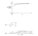
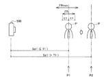
図8は、被写体距離Sdの推定方法を示す説明図である。図8には、対象画像TIの撮像時における撮像装置の結像面ISと被写体としての人物Pの顔との位置関係を示している。図8に示すように、レンズの主点UPと人物Pの顔との間の距離である被写体距離Sdは、人物Pの顔の位置を含み結像面ISに平行な面(以下「被写体面SS」とも呼ぶ)における撮像範囲の幅Wwと画角θとにより定まる。また、画角θは、レンズの焦点距離fと結像面ISの幅Wxとの関係により特定される。すなわち、下記の式(1)が成り立つ。
Sd:Ww=f:Wx ・・・(1)
FIG. 8 is an explanatory diagram showing a method for estimating the subject distance Sd. FIG. 8 shows the positional relationship between the imaging plane IS of the imaging device and the face of the person P as the subject at the time of capturing the target image TI. As shown in FIG. 8, the subject distance Sd, which is the distance between the principal point UP of the lens and the face of the person P, is a plane including the position of the face of the person P and parallel to the imaging plane IS (hereinafter referred to as “subject plane”). It is determined by the width Ww of the imaging range and the angle of view θ. The angle of view θ is specified by the relationship between the focal length f of the lens and the width Wx of the image plane IS. That is, the following formula (1) is established.
Sd: Ww = f: Wx (1)
また、被写体面SSにおける撮像範囲の幅Wwは、人物Pの顔の画像が対象画像TI(図6)において占める大きさに基づき特定される。すなわち、被写体面SSにおける幅Wwと人物Pの顔の幅Wfとの比は、対象画像TIにおける画像全体の幅Wwiと顔領域FAの幅Wfiとの比に等しいと考えられる(式(2)参照)。
Ww:Wf=Wwi:Wfi ・・・(2)
Further, the width Ww of the imaging range on the subject surface SS is specified based on the size occupied by the face image of the person P in the target image TI (FIG. 6). That is, the ratio between the width Ww on the subject surface SS and the width Wf of the face of the person P is considered to be equal to the ratio between the width Wwi of the entire image in the target image TI and the width Wfi of the face area FA (formula (2)). reference).
Ww: Wf = Wwi: Wfi (2)
上記式(1)および(2)から、下記の式(3)が導かれる。
Sd=(Wwi×Wf×f)/(Wfi×Wx) ・・・(3)
From the above formulas (1) and (2), the following formula (3) is derived.
Sd = (Wwi × Wf × f) / (Wfi × Wx) (3)
被写体距離推定部330の情報取得部340(図1)は、式(3)を用いた被写体距離Sdの算出に必要な情報を取得する。具体的には、情報取得部340は、対象画像TIを表す画像ファイルにメタデータとして付加されている対象画像TIの全体の幅Wwiの値(画素数)を取得すると共に、顔領域FA(図6)の幅Wfiの値(画素数)を算出する。顔領域FAの幅Wfiの算出は、例えば顔領域FAの2つの頂点の座標を用いて2つの頂点間の距離を算出することにより行う。なお、本実施例において、対象画像TIの全体の幅Wwiの値と顔領域FAの幅Wfiの値とは、対象画像TIの大きさに対する顔の画像の大きさを示す情報であり、本発明における第1の情報に相当する。
The information acquisition unit 340 (FIG. 1) of the subject
情報取得部340は、また、人物Pの顔の幅Wfの値として、予め設定され内部メモリ120(図1)に格納された典型的な人物の顔の幅(顔の現実の大きさ)の概略値(例えば200mm)を取得する。人物Pの顔の幅Wfの値は、本発明における第2の情報に相当する。 The information acquisition unit 340 also sets a typical person face width (actual face size) stored in the internal memory 120 (FIG. 1) as a value of the face width Wf of the person P. An approximate value (for example, 200 mm) is acquired. The value of the face width Wf of the person P corresponds to the second information in the present invention.
さらに、情報取得部340は、対象画像TIの画像ファイルの付加データに含まれる撮像時のレンズ焦点距離fの値を取得する。ここで、取得されるレンズの焦点距離fの値は、35mmフィルム換算値であり、撮像装置の実際の焦点距離(実焦点距離)とは異なる場合がある。このような場合には、情報取得部340は、結像面ISの幅Wxとして、予め設定された35mmフィルムの幅の値(=36mm)を取得する。なお、画像ファイルの付加データに実焦点距離のデータと撮像装置の撮像素子の幅のデータとが含まれている場合には、情報取得部340が、レンズの焦点距離fとして実焦点距離の値を取得し、結像面ISの幅Wxとして撮像素子の幅の値を取得するとしてもよい。また、画像ファイルの付加データに画角そのものを示すデータが含まれている場合には、情報取得部340が画角を示すデータを取得するとしてもよい。本実施例において、レンズの焦点距離fの値と結像面ISの幅Wxの値とは、対象画像TIの画角θを特定可能な情報であり、本発明における第3の情報に相当する。 Furthermore, the information acquisition unit 340 acquires the value of the lens focal length f at the time of imaging included in the additional data of the image file of the target image TI. Here, the value of the focal length f of the lens acquired is a 35 mm film equivalent value and may be different from the actual focal length (actual focal length) of the imaging apparatus. In such a case, the information acquisition unit 340 acquires a preset value of the width of the 35 mm film (= 36 mm) as the width Wx of the imaging plane IS. When the additional data of the image file includes the actual focal length data and the image sensor width data of the imaging device, the information acquisition unit 340 sets the actual focal length value as the focal length f of the lens. And the value of the width of the image sensor may be acquired as the width Wx of the imaging plane IS. In addition, when the additional data of the image file includes data indicating the angle of view, the information acquisition unit 340 may acquire data indicating the angle of view. In the present embodiment, the value of the focal length f of the lens and the value of the width Wx of the imaging plane IS are information that can specify the angle of view θ of the target image TI, and correspond to the third information in the present invention. .
被写体距離推定部330は、情報取得部340により取得された上記各情報(対象画像TIの全体の幅Wwiの値、顔領域FAの幅Wfiの値、人物Pの顔の幅Wfの値、レンズの焦点距離fの値、結像面ISの幅Wxの値)と、上記式(3)とを用いて、被写体距離Sdを算出(推定)する。
The subject
図4のステップS590では、変形量設定部290(図1)が、変形量(「変形の度合い」または「変形の程度」とも呼ぶ)を設定する。変形量設定部290による変形量の設定方法については、後述の「A−4.変形処理」において詳述する。 In step S590 of FIG. 4, the deformation amount setting unit 290 (FIG. 1) sets a deformation amount (also referred to as “degree of deformation” or “degree of deformation”). The method of setting the deformation amount by the deformation amount setting unit 290 will be described in detail in “A-4. Deformation process” described later.
ステップS600(図4)では、ステップS500で設定された変形領域TAに対し、変形処理が行われる。変形処理の具体的内容については、後述の「A−4.変形処理」において詳述する。 In step S600 (FIG. 4), a deformation process is performed on the deformation area TA set in step S500. The specific contents of the deformation process will be described in detail later in “A-4. Deformation process”.
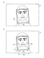
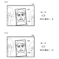
図9は、変形処理が行われた結果を示す説明図である。図9(a)は、図4のステップS600における変形処理が行われる前の対象画像TIを示しており、図9(b)は、変形処理後の対象画像TIを示している。図9(b)に示すように、変形処理後の対象画像TIでは、変形領域TA内の人物の顔の画像が細くなっている。なお、ステップS600における変形処理は対象画像TI中の変形領域TA内の画像にのみ施され、変形領域TAの外の画像は変形されない。その結果、画像の全体を過剰に変形させずに、被写体を変形させることができる。 FIG. 9 is an explanatory diagram showing a result of the deformation process. FIG. 9A shows the target image TI before the deformation process in step S600 of FIG. 4 is performed, and FIG. 9B shows the target image TI after the deformation process. As shown in FIG. 9B, in the target image TI after the deformation process, the face image of the person in the deformation area TA is thin. Note that the deformation process in step S600 is performed only on the image in the deformation area TA in the target image TI, and the image outside the deformation area TA is not deformed. As a result, the subject can be deformed without excessively deforming the entire image.
図9の例では、顔の左右の頬のライン(顔の輪郭)の画像が変形量DQだけ内側に移動している。この変形量DQは、図4のステップS590において設定された量である。このような変形処理によって、変形処理後の顔の画像の幅Wdは、変形前の顔の画像の幅Woと比べて、変形量DQの2倍だけ狭くなる。このように幅が狭くなるように画像を変形する理由は、画像の観察によって得られる被写体の印象を、実物の観察によって得られる印象に近づけるためである。 In the example of FIG. 9, the image of the cheek line (face outline) on the left and right sides of the face has moved inward by the deformation amount DQ. This deformation amount DQ is the amount set in step S590 of FIG. By such a deformation process, the width Wd of the face image after the deformation process becomes narrower by twice the deformation amount DQ than the width Wo of the face image before the deformation process. The reason why the image is deformed so as to be narrow in this way is to bring the impression of the subject obtained by observing the image closer to the impression obtained by observing the real object.
図10は、被写体の印象の違いを示す説明図である。図10中には、被写体Sと、人(観察者)の右目REと左目LEと、撮像装置としてのカメラCMとが示されている。図10では、観察者の上面から見た位置関係を示している。 FIG. 10 is an explanatory diagram showing the difference in the impression of the subject. In FIG. 10, a subject S, a right eye RE and a left eye LE of a person (observer), and a camera CM as an imaging device are shown. In FIG. 10, the positional relationship seen from the upper surface of the observer is shown.
図10の例では、説明を簡単にするために、上面から見た被写体Sの形状が半径rの円であるものと仮定している。なお、このような丸い被写体Sとしては、人の頭に限らず、種々の被写体(例えば、円筒形の建物やボール)が挙げられる。この被写体Sは、2つの目RE、LEの真正面に位置している。また、カメラCMは、2つの目RE、LEの中点MPに配置されている。すなわち、カメラCMは、観察者とほぼ同じ位置から、被写体Sを見る。なお、図中のx軸は、被写体Sの中心Cと、中点MPとを通る座標軸である。y軸は、中心Cを通り、x軸に垂直な座標軸である。2つの目RE、LEは、このy軸に沿って並んでいる。距離Lは、2つの目RE、LEの間の距離を示している。また、距離dは、中心Cと目RE、LEとの間のx軸に沿った距離を示している。 In the example of FIG. 10, to simplify the description, it is assumed that the shape of the subject S viewed from above is a circle with a radius r. Note that such a round subject S is not limited to a human head, and includes various subjects (for example, a cylindrical building or a ball). The subject S is located in front of the two eyes RE and LE. The camera CM is disposed at the midpoint MP of the two eyes RE and LE. That is, the camera CM views the subject S from almost the same position as the observer. Note that the x-axis in the figure is a coordinate axis passing through the center C of the subject S and the midpoint MP. The y-axis is a coordinate axis that passes through the center C and is perpendicular to the x-axis. The two eyes RE and LE are arranged along this y-axis. The distance L indicates the distance between the two eyes RE and LE. A distance d indicates a distance along the x-axis between the center C and the eyes RE and LE.
図10中の第1幅W1は、被写体Sの幅を示している。この第1幅W1は、カメラCMから見える部分の幅を示している。カメラCMから見える部分は、被写体Sの表面の内の、カメラ被写体範囲SRC内の部分である。このカメラ被写体範囲SRCは、カメラCMの視野の全範囲の内の被写体Sが占める範囲を示している。 A first width W1 in FIG. 10 indicates the width of the subject S. The first width W1 indicates the width of the portion visible from the camera CM. The portion visible from the camera CM is a portion of the surface of the subject S within the camera subject range SRC. The camera subject range SRC indicates a range occupied by the subject S in the entire range of the field of view of the camera CM.
図10中の第2幅W2も、被写体Sの幅を示している。ただし、この第2幅W2は、両目RE、LEから見える部分の幅を示している。両目RE、LEから見える部分は、被写体Sの表面の内の、右被写体範囲SRRと左被写体範囲SRLとの重なる範囲の内の部分である。右被写体範囲SRRは、右目REの視野の全範囲の内の被写体Sが占める範囲を示し、左被写体範囲SRLは、左目LEの視野の全範囲の内の被写体Sが占める範囲を示している。 The second width W2 in FIG. 10 also indicates the width of the subject S. However, this 2nd width W2 has shown the width | variety of the part visible from both eyes RE and LE. The portion visible from both eyes RE and LE is the portion of the surface of the subject S within the range where the right subject range SRR and the left subject range SRL overlap. The right subject range SRR indicates a range occupied by the subject S within the entire range of the field of view of the right eye RE, and the left subject range SRL indicates a range occupied by the subject S within the entire range of the field of view of the left eye LE.
図10に示すように、右目REと左目LEとの間では、被写体Sの見える部分が異なっている。すなわち、右目REから見える部分は右目RE側に偏っており、左目LEから見える部分は左目LE側に偏っている。このような場合には、人(観察者)による被写体Sの認識は、両目RE、LEに共通な可視部分から強い影響を受けると推定される。例えば、人は、両目RE、LEに共通な可視部分の幅W2が被写体Sの幅であるという認識を持つと推定される。 As shown in FIG. 10, the visible portion of the subject S is different between the right eye RE and the left eye LE. That is, the part visible from the right eye RE is biased toward the right eye RE, and the part visible from the left eye LE is biased toward the left eye LE. In such a case, it is estimated that the recognition of the subject S by a person (observer) is strongly influenced by the visible portion common to both eyes RE and LE. For example, it is estimated that a person has the recognition that the width W2 of the visible portion common to both eyes RE and LE is the width of the subject S.
また、図10に示すように、第2幅W2は第1幅W1よりも狭い。すなわち、撮像によって生成された画像を観察すると、実際の被写体Sを観察したときと比べて幅が広い印象を受ける。そこで、図9(b)に示すように幅が狭くなるように画像を変形することによって、画像の観察によって得られる被写体の印象を、実物の観察によって得られる印象に近づけることができる。 Further, as shown in FIG. 10, the second width W2 is narrower than the first width W1. That is, when an image generated by imaging is observed, the impression is wider than when an actual subject S is observed. Therefore, by deforming the image so that the width becomes narrow as shown in FIG. 9B, the impression of the subject obtained by observing the image can be made closer to the impression obtained by observing the real object.
図11は、第1幅W1に対する第2幅W2の比率Riと、距離dとの関係を示すグラフである。横軸は距離dを示し、縦軸は比率Riを示している。また、図11には、これらの幅W1、W2を示す関数も示されている。これらの幅W1、W2は、半径rと距離dと距離Lとの関数で表されている。なお、図11のグラフでは、半径rと距離Lとは固定されている。 FIG. 11 is a graph showing the relationship between the ratio Ri of the second width W2 to the first width W1 and the distance d. The horizontal axis indicates the distance d, and the vertical axis indicates the ratio Ri. FIG. 11 also shows functions indicating these widths W1 and W2. These widths W1 and W2 are expressed as a function of the radius r, the distance d, and the distance L. In the graph of FIG. 11, the radius r and the distance L are fixed.
図11に示すように、比率Ri(W2/W1)は、距離dが小さいほど小さい。また、この比率Ri(W2/W1)は、「1.0」よりも小さく、距離dが大きいほど「1.0」に近くなる。 As shown in FIG. 11, the ratio Ri (W2 / W1) is smaller as the distance d is smaller. Further, the ratio Ri (W2 / W1) is smaller than “1.0”, and becomes closer to “1.0” as the distance d is larger.
図12(a)は、変形量DQと被写体距離Sdとの関係を示すグラフである。図12(b)は、変形前の幅Woに対する変形後の幅Wdの比率Rwと、被写体距離Sdとの関係を示すグラフである。これらのグラフでは、横軸がステップS570(図4)で推定された被写体距離Sdを示している。 FIG. 12A is a graph showing the relationship between the deformation amount DQ and the subject distance Sd. FIG. 12B is a graph showing the relationship between the ratio Rw of the width Wd after deformation to the width Wo before deformation and the subject distance Sd. In these graphs, the horizontal axis indicates the subject distance Sd estimated in step S570 (FIG. 4).
図12(a)に示す変形量DQは、図12(b)に示す比率Rwが図11に示す比率Riと同じとなるように、予め設定されている。この結果、被写体距離Sdの値が小さいほど、変形量DQは大きな値に設定される。ここで、距離Lと半径rとは所定値に予め固定されている。目の距離Lとしては、例えば、100mmを採用可能である。また、半径r、すなわち、被写体Sの大きさとしては、被写体を代表する値(例えば、100mm)を採用可能である。なお、本実施例では、変形量DQは、変形領域TA内における幅の変化率(この場合は減少率)を示している。 The deformation amount DQ shown in FIG. 12A is set in advance so that the ratio Rw shown in FIG. 12B is the same as the ratio Ri shown in FIG. As a result, the smaller the subject distance Sd, the larger the deformation amount DQ is set. Here, the distance L and the radius r are fixed to predetermined values in advance. As the distance L between eyes, for example, 100 mm can be adopted. As the radius r, that is, the size of the subject S, a value representative of the subject (for example, 100 mm) can be adopted. In the present embodiment, the deformation amount DQ indicates the rate of change in width within the deformation area TA (in this case, the decrease rate).
上述した図4のステップS590では、変形量設定部290(図1)が、予め設定された図12(a)に示す対応関係を用いて、ステップS570において算出(推定)された被写体距離Sdから変形量DQを決定する。図4のステップS600では、このように決定された変形量DQを利用して画像が変形される(図9(b))。その結果、被写体距離Sdに合わせて画像を適切に変形させることができる。具体的には、画像の観察によって得られる被写体の印象を、実物の観察によって得られる印象に近づけることができる。 In step S590 in FIG. 4 described above, the deformation amount setting unit 290 (FIG. 1) uses the preset correspondence relationship shown in FIG. 12A from the subject distance Sd calculated (estimated) in step S570. A deformation amount DQ is determined. In step S600 of FIG. 4, the image is deformed using the deformation amount DQ determined in this way (FIG. 9B). As a result, the image can be appropriately deformed according to the subject distance Sd. Specifically, the impression of the subject obtained by observing the image can be made closer to the impression obtained by observing the real object.
ステップS200(図3)では、顔形状補正部200(図1)が、顔形状補正後の対象画像TIを表示部150に表示するよう表示処理部310に指示する。図13は、顔形状補正後の対象画像TIが表示された表示部150の状態の一例を示す説明図である。顔形状補正後の対象画像TIが表示された表示部150により、ユーザは、補正結果を確認することができる。ユーザが補正結果に満足せず「戻る」ボタンを選択した場合には、例えば表示部150に図5に示した変形タイプおよび変形度合いを選択する画面が表示され、ユーザによる変形タイプや変形度合いの再度の設定が実行される。ユーザが補正結果に満足し、「印刷」ボタンを選択した場合には、以下の補正画像印刷処理が開始される。
In step S200 (FIG. 3), the face shape correction unit 200 (FIG. 1) instructs the
ステップS300(図3)では、印刷処理部320(図1)が、プリンタエンジン160を制御して、顔形状補正処理後の対象画像TIの印刷を行う。印刷処理部320は、顔形状補正処理後の対象画像TIの画像データに、解像度変換やハーフトーン処理などの処理を施して印刷データを生成する。生成された印刷データは、印刷処理部320からプリンタエンジン160に供給され、プリンタエンジン160は対象画像TIの印刷を実行する。これにより、顔形状補正後の対象画像TIの印刷が完了する。
In step S300 (FIG. 3), the print processing unit 320 (FIG. 1) controls the
以上説明したように、本実施例のプリンタ100では、対象画像TIの全体の幅Wwiの値、顔領域FAの幅Wfiの値、人物Pの顔の幅Wfの値、レンズの焦点距離fの値、結像面ISの幅Wxの値を用いて、上記式(3)により、対象画像TIにおける被写体距離Sdを推定することができる。
As described above, in the
また、本実施例のプリンタ100では、推定された被写体距離Sdに基づき、被写体距離Sdが小さいほど変形の度合いが大きくなる(変形量が大きくなる)ように画像変形における変形の度合い(変形量)が設定され、設定された変形量DQを利用して画像の変形処理が行われる。そのため、画像の観察によって得られる被写体の印象を実物の観察によって得られる印象に近づけるような、画像の変形処理を実現することができる。
Further, in the
なお、本実施例における画像の変形処理は、本発明における特定の処理に相当し、本実施例において画像の変形処理を行う顔形状補正部200は本発明における特定処理実行部に相当する。
The image deformation process in the present embodiment corresponds to a specific process in the present invention, and the face
A−3.変形領域の設定:
上述した顔形状補正処理(図4)における変形領域TAの設定処理(ステップS500)について詳述する。図14は、顔領域FAの検出結果の一例を示す説明図である。図14に示すように、図4のステップS130において、対象画像TIから顔領域FAが検出されている。図14に示した基準線RLは、顔領域FAの高さ方向(上下方向)を定義すると共に、顔領域FAの幅方向(左右方向)の中心を示す線である。すなわち、基準線RLは、矩形の顔領域FAの重心を通り、顔領域FAの高さ方向(上下方向)に沿った境界線に平行な直線である。
A-3. Deformation area settings:
The deformation area TA setting process (step S500) in the face shape correction process (FIG. 4) described above will be described in detail. FIG. 14 is an explanatory diagram showing an example of the detection result of the face area FA. As shown in FIG. 14, in step S130 of FIG. 4, a face area FA is detected from the target image TI. The reference line RL shown in FIG. 14 is a line that defines the height direction (vertical direction) of the face area FA and indicates the center in the width direction (horizontal direction) of the face area FA. That is, the reference line RL is a straight line that passes through the center of gravity of the rectangular face area FA and is parallel to the boundary line along the height direction (vertical direction) of the face area FA.
変形領域TAは、顔領域FAに基づき設定される。ここで、上述したように、顔領域FAの検出に用いられる公知の顔検出方法(テンプレートを利用したパターンマッチングによる方法等)は、顔全体や顔の部位(目や口等)について位置や傾き(角度)を詳細に検出するものではなく、対象画像TI中から顔の画像が概ね含まれると考えられる領域を顔領域FAとして設定するものである。他方、顔の画像は、一般に、観察者の注目度が高いため、顔領域FAに基づき設定された変形領域TAと顔の画像との位置や角度の関係によっては、顔形状補正後の画像が不自然なものとなる可能性がある。そこで、本実施例では、より自然で好ましい顔形状補正が実現されるように、ステップS130で検出された顔領域FAについて、以下に説明する位置調整および傾き調整を行うものとしている。 The deformation area TA is set based on the face area FA. Here, as described above, a known face detection method (such as a pattern matching method using a template) used for detection of the face area FA is based on the position and inclination of the entire face or face part (eyes, mouth, etc.). The (angle) is not detected in detail, and an area that is considered to include a face image from the target image TI is set as the face area FA. On the other hand, since the face image generally has a high degree of attention of the observer, the image after the face shape correction depends on the position and angle relationship between the deformation area TA set based on the face area FA and the face image. It can be unnatural. Therefore, in this embodiment, the position adjustment and the inclination adjustment described below are performed on the face area FA detected in step S130 so that more natural and preferable face shape correction is realized.
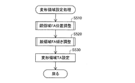
図15は、変形領域設定処理の流れを示すフローチャートである。ステップS510では、顔領域調整部230(図1)が、ステップS130(図4)で検出された顔領域FAの高さ方向の位置調整を行う。ここで、顔領域FAの高さ方向の位置調整とは、顔領域FAの基準線RL(図14参照)に沿った位置を調整して、対象画像TIにおける顔領域FAを再設定することを意味している。 FIG. 15 is a flowchart showing the flow of the deformation area setting process. In step S510, the face area adjustment unit 230 (FIG. 1) adjusts the position of the face area FA detected in step S130 (FIG. 4) in the height direction. Here, the position adjustment of the face area FA in the height direction means that the position along the reference line RL (see FIG. 14) of the face area FA is adjusted to reset the face area FA in the target image TI. I mean.
図16は、顔領域FAの高さ方向の位置調整処理の流れを示すフローチャートである。ステップS511では、顔領域調整部230(図1)が、特定領域SAを設定する。ここで、特定領域SAとは、対象画像TI上の領域であって、顔領域FAの高さ方向の位置調整を実行する際に参照する所定の参照被写体の画像を含む領域である。参照被写体は、例えば「目」に設定することができ、その場合、特定領域SAは「目」の画像を含む領域として設定される。 FIG. 16 is a flowchart showing the flow of position adjustment processing in the height direction of the face area FA. In step S511, the face area adjustment unit 230 (FIG. 1) sets the specific area SA. Here, the specific area SA is an area on the target image TI and includes an image of a predetermined reference subject that is referred to when the position adjustment of the face area FA in the height direction is executed. The reference subject can be set to, for example, “eyes”. In this case, the specific area SA is set as an area including an image of “eyes”.
図17は、特定領域SAの一例を示す説明図である。本実施例では、顔領域調整部230(図1)が、特定領域SAを顔領域FAとの関係に基づいて設定する。具体的には、顔領域FAの大きさを、基準線RLに直行する方向および基準線RLに平行な方向に、所定比率で縮小(または拡大)した大きさの領域であって、顔領域FAの位置と所定の位置関係を有する領域が、特定領域SAとして設定される。すなわち、本実施例では、顔領域検出部220により検出された顔領域FAとの関係に基づき特定領域SAを設定すれば、特定領域SAが両方の目の画像を含む領域となるように、上記所定比率や所定の位置関係が予め設定されている。なお、特定領域SAは、目の画像とまぎらわしい画像(例えば髪の毛の画像)がなるべく含まれないように、両目の画像を含む限りにおいて、なるべく小さい領域として設定されることが好ましい。
FIG. 17 is an explanatory diagram illustrating an example of the specific area SA. In the present embodiment, the face area adjustment unit 230 (FIG. 1) sets the specific area SA based on the relationship with the face area FA. Specifically, the face area FA has a size that is reduced (or enlarged) by a predetermined ratio in a direction perpendicular to the reference line RL and a direction parallel to the reference line RL. An area having a predetermined positional relationship with the position is set as the specific area SA. That is, in the present embodiment, when the specific area SA is set based on the relationship with the face area FA detected by the face
また、図17に示すように、特定領域SAは、基準線RLに対して対称な矩形形状の領域として設定される。特定領域SAは、基準線RLにより、向かって左側の領域(以下「左分割特定領域SA(l)」とも呼ぶ)と、向かって右側の領域(以下「右分割特定領域SA(r)」とも呼ぶ)とに分割される。特定領域SAは、左分割特定領域SA(l)と右分割特定領域SA(r)とのそれぞれに片目の画像が含まれるように設定される。 As shown in FIG. 17, the specific area SA is set as a rectangular area that is symmetrical with respect to the reference line RL. The specific area SA is defined as an area on the left side (hereinafter also referred to as “left divided specific area SA (l)”) and an area on the right side (hereinafter referred to as “right divided specific area SA (r)”) by the reference line RL. Called). The specific area SA is set so that the image of one eye is included in each of the left divided specific area SA (l) and the right divided specific area SA (r).
ステップS512(図16)では、顔領域調整部230(図1)が、特定領域SAにおける目の画像の位置を検出するための評価値を算出する。図18は、評価値の算出方法の一例を示す説明図である。本実施例では、RGB画像データとしての対象画像TIの各画素のR値(R成分値)が評価値の算出に用いられる。これは、肌の部分の画像と目の部分の画像とではR値の差が大きいため、R値を評価値の算出に用いることにより、目の画像の検出精度を向上させることができると考えられるからである。また、本実施例では、対象画像TIのデータがRGBデータとして取得されているため、R値を評価値の算出に用いることにより、評価値の算出の効率化を図ることができるからでもある。なお、図18に示すように、評価値の算出は、2つの分割特定領域(右分割特定領域SA(r)および左分割特定領域SA(l))のそれぞれについて個別に行われる。 In step S512 (FIG. 16), the face area adjustment unit 230 (FIG. 1) calculates an evaluation value for detecting the position of the eye image in the specific area SA. FIG. 18 is an explanatory diagram illustrating an example of an evaluation value calculation method. In this embodiment, the R value (R component value) of each pixel of the target image TI as RGB image data is used for calculation of the evaluation value. This is because the difference in the R value is large between the skin image and the eye image, and thus the detection accuracy of the eye image can be improved by using the R value for calculating the evaluation value. Because it is. In addition, in the present embodiment, since the data of the target image TI is acquired as RGB data, it is possible to increase the efficiency of calculation of the evaluation value by using the R value for calculation of the evaluation value. As shown in FIG. 18, the evaluation value is calculated individually for each of the two divided specific areas (the right divided specific area SA (r) and the left divided specific area SA (l)).
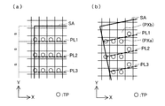
顔領域調整部230は、図18に示すように、分割特定領域(右分割特定領域SA(r)および左分割特定領域SA(l))内に、基準線RLと直行するn本の直線(以下「対象画素特定線PL1〜PLn」と呼ぶ)を設定する。対象画素特定線PL1〜PLnは、分割特定領域の高さ(基準線RLに沿った大きさ)を(n+1)等分する直線である。すなわち、対象画素特定線PL同士の間隔は、すべて等間隔sである。
As shown in FIG. 18, the face
顔領域調整部230は、対象画素特定線PL1〜PLnのそれぞれについて、対象画像TIを構成する画素の中から評価値の算出に用いる画素(以下「評価対象画素TP」と呼ぶ)を選択する。図19は、評価対象画素TPの選択方法の一例を示す説明図である。顔領域調整部230は、対象画像TIを構成する画素の内、対象画素特定線PLと重なる画素を評価対象画素TPとして選択する。図19(a)は、対象画素特定線PLが対象画像TIの画素の行方向(図19のX方向)と平行である場合を示している。この場合には、各対象画素特定線PLと重なる画素行上の画素(図19(a)において○印を付した画素)が、各対象画素特定線PLについての評価対象画素TPとして選択される。
The face
一方、顔領域FAの検出方法や特定領域SAの設定方法によっては、図19(b)に示すように、対象画素特定線PLが対象画像TIの画素の行方向(X方向)と平行とはならない場合も生ずる。このような場合にも、原則として、各対象画素特定線PLと重なる画素が、各対象画素特定線PLについての評価対象画素TPとして選択される。ただし、例えば図19(b)における対象画素特定線PL1と画素PXaおよびPXbとの関係のように、ある対象画素特定線PLが、対象画像TIの画素マトリクスの同一列に位置する(すなわちY座標が同一の)2つの画素と重なる場合には、重なり部分の距離のより短い方の画素(例えば画素PXb)は評価対象画素TPから除外される。すなわち、各対象画素特定線PLについて、画素マトリクスの1つの列からは1つの画素のみが評価対象画素TPとして選択される。 On the other hand, depending on the detection method of the face area FA and the setting method of the specific area SA, as shown in FIG. 19B, the target pixel specific line PL is parallel to the row direction (X direction) of the pixels of the target image TI. There may be cases where this is not possible. Even in such a case, in principle, a pixel that overlaps each target pixel specifying line PL is selected as the evaluation target pixel TP for each target pixel specifying line PL. However, for example, as in the relationship between the target pixel specifying line PL1 and the pixels PXa and PXb in FIG. 19B, a certain target pixel specifying line PL is located in the same column of the pixel matrix of the target image TI (that is, the Y coordinate). In the case where two pixels overlap with each other, the pixel having the shorter overlap distance (for example, the pixel PXb) is excluded from the evaluation target pixel TP. That is, for each target pixel specifying line PL, only one pixel is selected as the evaluation target pixel TP from one column of the pixel matrix.
なお、対象画素特定線PLの傾きが、X方向に対して45度を超える場合には、上記説明において画素マトリクスの列と行との関係が逆転し、画素マトリクスの1つの行から1つの画素のみが評価対象画素TPとして選択されることとなる。また、対象画像TIと特定領域SAとの大きさの関係によっては、1つの画素が複数の対象画素特定線PLについての評価対象画素TPとして選択される場合もある。 When the inclination of the target pixel specifying line PL exceeds 45 degrees with respect to the X direction, the relationship between the column and the row of the pixel matrix is reversed in the above description, and one pixel from one row of the pixel matrix is reversed. Only the pixel to be evaluated TP is selected. Further, depending on the size relationship between the target image TI and the specific area SA, one pixel may be selected as the evaluation target pixel TP for a plurality of target pixel specific lines PL.
顔領域調整部230は、対象画素特定線PLのそれぞれについて、評価対象画素TPのR値の平均値を評価値として算出する。ただし、本実施例では、各対象画素特定線PLについて、選択された複数の評価対象画素TPの内、R値の大きい一部の画素を評価値の算出対象から除外するものとしている。具体的には、例えば、ある対象画素特定線PLについてk個の評価対象画素TPが選択された場合、評価対象画素TPが、R値の比較的大きい0.75k個の画素により構成される第1グループと、比較的R値の小さい0.25k個の画素により構成される第2グループとの2グループに分けられ、第2グループに属する画素のみが評価値としてのR値の平均値の算出対象となる。このように一部の評価対象画素TPを評価値の算出対象から除外する理由については後述する。
The face
以上のように、本実施例では、顔領域調整部230により各対象画素特定線PLについての評価値が算出される。ここで、対象画素特定線PLは基準線RLに直行する直線であるため、評価値は、基準線RLに沿った複数の位置(評価位置)について算出されると表現することができる。また、評価値は、各評価位置について、基準線RLに直行する方向に沿った画素値の分布の特徴を表す値と表現することができる。
As described above, in this embodiment, the face
ステップS513(図16)では、顔領域調整部230(図1)が、特定領域SAにおける目の位置を検出し、検出結果に基づき高さ基準点Rhを決定する。まず、顔領域調整部230は、図18の右側に示すように、各分割特定領域について、基準線RLに沿った評価値(R値の平均値)の分布を表す曲線を作成し、評価値が極小値をとる基準線RL方向に沿った位置を目の位置Ehとして検出する。なお、左分割特定領域SA(l)における目の位置EhをEh(l)と表し、右分割特定領域SA(r)における目の位置EhをEh(r)と表わす。
In step S513 (FIG. 16), the face area adjustment unit 230 (FIG. 1) detects the position of the eye in the specific area SA, and determines the height reference point Rh based on the detection result. First, as shown on the right side of FIG. 18, the face
黄色人種の場合、分割特定領域中の肌の画像を表す部分はR値が大きい一方、目(より詳細には目の中央の黒目部分)の画像を表す部分はR値が小さいと考えられる。そのため、上述のように、評価値(R値の平均値)が極小値をとる基準線RLに沿った位置を目の位置Ehと判断することが可能となる。但し、他の人種(白色人種や黒色人種)を対象とする場合には、他の評価値(例えば、輝度や明度やB値)が用いられる。 In the case of the yellow race, the portion representing the skin image in the divided specific region has a large R value, while the portion representing the image of the eye (more specifically, the black eye portion at the center of the eye) has a small R value. . Therefore, as described above, the position along the reference line RL where the evaluation value (average value of R values) takes the minimum value can be determined as the eye position Eh. However, when other races (white race or black race) are targeted, other evaluation values (for example, luminance, brightness, B value) are used.
なお、図18に示すように、分割特定領域には、目の画像以外にもR値の小さい他の画像(例えば、眉や髪の毛の画像)が含まれている場合もある。そのため、顔領域調整部230は、基準線RLに沿った評価値の分布を表す曲線が複数の極小値をとる場合には、極小値をとる位置の内、最も下側の位置を目の位置Ehと判断する。一般に、目の画像より上側には眉や髪の毛等のR値の小さい画像が位置することが多い一方、目の画像より下側にはR値の小さい画像が位置することが少ないと考えられることから、このような判断が可能となる。
As illustrated in FIG. 18, the divided specific region may include other images having a small R value (for example, images of eyebrows and hairs) in addition to the eye image. Therefore, when the curve representing the distribution of evaluation values along the reference line RL has a plurality of minimum values, the face
また、上記曲線が、目の画像の位置よりも下側(主に肌の画像に対応した位置)であっても、評価値が大きいながらも極小値をとる可能性があるため、極小値の内、所定の閾値より大きいものは無視するものとしてもよい。あるいは、単純に、各対象画素特定線PLについて算出された評価値の内の最小値に対応した対象画素特定線PLの位置を目の位置Ehとしてもよい。 Even if the curve is below the position of the eye image (mainly the position corresponding to the image of the skin), the evaluation value is large, but may have a minimum value. Of these, those larger than a predetermined threshold may be ignored. Alternatively, the position of the target pixel specifying line PL corresponding to the minimum value among the evaluation values calculated for each target pixel specifying line PL may be simply set as the eye position Eh.
なお、本実施例では、顔において周囲との色の差が比較的大きいと考えられる部位である目(目の中央の黒目部分)を顔領域FAの位置調整の参照被写体として用いている。しかし、評価値としてのR値の平均値は、対象画素特定線PL上の複数の評価対象画素TPを対象として算出されるため、例えば、黒目の周縁の白目部分の画像の影響により、黒目部分の検出の精度が低下する怖れがある。本実施例では、上述したように、参照被写体とは色の差が大きいと考えられる一部の評価対象画素TP(例えば上述した第1のグループに属する比較的R値の大きい画素)を評価値の算出対象から除外することにより、参照被写体の検出精度をより向上させている。 In the present embodiment, the eye (the black eye part at the center of the eye), which is considered to be a part where the color difference between the face and the surroundings is relatively large, is used as a reference subject for position adjustment of the face area FA. However, since the average value of the R values as the evaluation values is calculated for a plurality of evaluation target pixels TP on the target pixel specifying line PL, for example, due to the influence of the image of the white part of the periphery of the black eye, the black eye part There is a fear that the accuracy of detection will be reduced. In the present embodiment, as described above, some evaluation target pixels TP (for example, pixels having a relatively large R value belonging to the first group described above) that are considered to have a large color difference from the reference subject are evaluated values. Is excluded from the calculation target, the reference subject detection accuracy is further improved.
次に、顔領域調整部230は、検出された目の位置Ehに基づき高さ基準点Rhを決定する。図20は、高さ基準点Rhの決定方法の一例を示す説明図である。高さ基準点Rhは、顔領域FAの高さ方向の位置調整の際に、基準として用いられる点である。本実施例では、図20に示すように、左右2つの目の位置Eh(l)およびEh(r)の中間に位置する基準線RL上の点が高さ基準点Rhとして設定される。すなわち、左の目の位置Eh(l)を示す直線EhL(l)と基準線RLとの交点と、右の目の位置Eh(r)を示す直線EhL(r)と基準線RLとの交点と、の中点が、高さ基準点Rhとして設定される。
Next, the face
なお、本実施例では、顔領域調整部230が、検出された目の位置Ehに基づき、顔画像の概略の傾き角(以下「概略傾き角RI」と呼ぶ)を算出するものとしている。顔画像の概略傾き角RIは、対象画像TI中の顔の画像が、顔領域FAの基準線RLに対して概ねどれぐらい傾いているかを推定した角度である。図21は、概略傾き角RIの算出方法の一例を示す説明図である。図21に示すように、顔領域調整部230は、まず、左分割特定領域SA(l)の幅Ws(l)を半分に分割する直線と直線EhL(l)との交点IP(l)と、右分割特定領域SA(r)の幅Ws(r)を半分に分割する直線と直線EhL(r)との交点IP(r)とを決定する。そして、交点IP(l)と交点IP(r)とを結ぶ直線に直交する直線ILと、基準線RLとのなす角が、概略傾き角RIとして算出される。
In the present embodiment, the face
ステップS514(図16)では、顔領域調整部230(図1)が、顔領域FAの高さ方向の位置調整を行う。図22は、顔領域FAの高さ方向の位置調整方法の一例を示す説明図である。顔領域FAの高さ方向の位置調整は、高さ基準点Rhが、位置調整後の顔領域FAにおける所定の位置に位置することとなるように、顔領域FAを再設定することにより行う。具体的には、図22に示すように、高さ基準点Rhが、顔領域FAの高さHfを所定の比率r1対r2で分けるような位置に位置することとなるように、顔領域FAが基準線RLに沿って上下に位置調整される。図22の例では、破線で示した調整前の顔領域FAを上方向に移動することにより、実線で示した調整後の顔領域FAが再設定されている。 In step S514 (FIG. 16), the face area adjustment unit 230 (FIG. 1) adjusts the position of the face area FA in the height direction. FIG. 22 is an explanatory diagram illustrating an example of a position adjustment method in the height direction of the face area FA. The position adjustment of the face area FA in the height direction is performed by resetting the face area FA so that the height reference point Rh is positioned at a predetermined position in the face area FA after the position adjustment. Specifically, as shown in FIG. 22, the face area FA is such that the height reference point Rh is located at a position where the height Hf of the face area FA is divided by a predetermined ratio r1 to r2. Is vertically adjusted along the reference line RL. In the example of FIG. 22, the face area FA after adjustment indicated by the solid line is reset by moving the face area FA before adjustment indicated by the broken line upward.
顔領域FAの位置調整の後、ステップS520(図15)では、顔領域調整部230(図1)が、顔領域FAの傾き調整(角度調整)を行う。ここで、顔領域FAの傾き調整とは、対象画像TIにおける顔領域FAの傾きを顔の画像の傾きに適合するように調整して、顔領域FAを再設定することを意味している。本実施例では、顔領域FAの傾き調整を実行する際に参照する所定の参照被写体は、「両目」と設定されている。本実施例における顔領域FAの傾き調整では、傾き調整の調整角度の選択肢を表す複数の評価方向が設定され、各評価方向に対応した評価特定領域ESAが両目の画像を含む領域として設定される。そして、各評価方向について評価特定領域ESAの画像の画素値に基づき評価値が算出され、評価値に基づき決定される傾き調整の調整角度を用いて顔領域FAの傾きが調整される。 After the position adjustment of the face area FA, in step S520 (FIG. 15), the face area adjustment unit 230 (FIG. 1) performs the inclination adjustment (angle adjustment) of the face area FA. Here, the tilt adjustment of the face area FA means that the face area FA is adjusted by adjusting the tilt of the face area FA in the target image TI to match the tilt of the face image, and the face area FA is reset. In the present embodiment, the predetermined reference subject that is referred to when the inclination adjustment of the face area FA is executed is set to “both eyes”. In the inclination adjustment of the face area FA in the present embodiment, a plurality of evaluation directions representing adjustment angle adjustment options for inclination adjustment are set, and the evaluation specific area ESA corresponding to each evaluation direction is set as an area including the images of both eyes. . Then, an evaluation value is calculated based on the pixel value of the image in the evaluation specific area ESA for each evaluation direction, and the inclination of the face area FA is adjusted using the adjustment angle of the inclination adjustment determined based on the evaluation value.
図23は、第1実施例における顔領域FAの傾き調整処理の流れを示すフローチャートである。また、図24は、顔領域FAの傾き調整のための評価値の算出方法の一例を示す説明図である。ステップS521(図23)では、顔領域調整部230(図1)が、初期評価特定領域ESA(0)を設定する。初期評価特定領域ESA(0)は、顔領域FAの位置調整後の基準線RL(図22参照)と平行な方向(以下「初期評価方向」とも呼ぶ)に対応付けられた評価特定領域ESAである。本実施例では、位置調整後の顔領域FAに対応した特定領域SA(図22参照)が、そのまま初期評価特定領域ESA(0)として設定される。なお、顔領域FAの傾き調整における評価特定領域ESAは、顔領域FAの位置調整時の特定領域SAとは異なり、左右2つの領域に分割されることはない。図24の最上段には、設定された初期評価特定領域ESA(0)が示されている。 FIG. 23 is a flowchart showing the flow of the inclination adjustment process of the face area FA in the first embodiment. FIG. 24 is an explanatory diagram showing an example of an evaluation value calculation method for adjusting the inclination of the face area FA. In step S521 (FIG. 23), the face area adjustment unit 230 (FIG. 1) sets an initial evaluation specific area ESA (0). The initial evaluation specific area ESA (0) is an evaluation specific area ESA associated with a direction (hereinafter also referred to as “initial evaluation direction”) parallel to the reference line RL (see FIG. 22) after the position adjustment of the face area FA. is there. In the present embodiment, the specific area SA (see FIG. 22) corresponding to the face area FA after position adjustment is set as the initial evaluation specific area ESA (0) as it is. Note that the evaluation specific area ESA in the adjustment of the inclination of the face area FA is not divided into two areas on the left and right, unlike the specific area SA in the position adjustment of the face area FA. 24 shows the set initial evaluation specific area ESA (0).
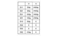
ステップS522(図23)では、顔領域調整部230(図1)が、複数の評価方向と各評価方向に対応した評価特定領域ESAとを設定する。複数の評価方向は、傾き調整の調整角度の選択肢を表す方向として設定される。本実施例では、基準線RLとのなす角が所定の範囲内である複数の評価方向線ELが設定され、評価方向線ELと平行な方向が評価方向として設定される。図24に示すように、基準線RLを初期評価特定領域ESA(0)の中心点(重心)CPを中心として反時計回りおよび時計回りに所定の角度α刻みで回転させることにより定まる直線が、複数の評価方向線ELとして設定される。なお、基準線RLとのなす角がφ度である評価方向線ELをEL(φ)と表す。 In step S522 (FIG. 23), the face area adjustment unit 230 (FIG. 1) sets a plurality of evaluation directions and evaluation specific areas ESA corresponding to the respective evaluation directions. The plurality of evaluation directions are set as directions representing options of adjustment angles for tilt adjustment. In this embodiment, a plurality of evaluation direction lines EL whose angles with the reference line RL are within a predetermined range are set, and a direction parallel to the evaluation direction line EL is set as the evaluation direction. As shown in FIG. 24, a straight line determined by rotating the reference line RL counterclockwise and clockwise around the center point (center of gravity) CP of the initial evaluation specific area ESA (0) at a predetermined angle α, It is set as a plurality of evaluation direction lines EL. Note that the evaluation direction line EL whose angle with the reference line RL is φ degrees is represented as EL (φ).
本実施例では、上述した各評価方向線ELと基準線RLとのなす角についての所定の範囲は±20度と設定される。ここで本明細書では、基準線RLを時計回りに回転させたときの回転角は正の値で表され、基準線RLを反時計回りに回転させたときの回転角は負の値で表される。顔領域調整部230は、基準線RLを反時計回りおよび時計回りにα度、2α度・・・と20度を超えない範囲で回転角を増加させつつ回転させ、複数の評価方向線ELを設定する。図24には、基準線RLを−α度,−2α度,α度回転させることによりそれぞれ定まる評価方向線EL(EL(−α),EL(−2α),EL(α))が示されている。なお、基準線RLは、評価方向線EL(0)とも表現できる。
In the present embodiment, the predetermined range for the angle formed by each evaluation direction line EL and the reference line RL is set to ± 20 degrees. Here, in this specification, the rotation angle when the reference line RL is rotated clockwise is represented by a positive value, and the rotation angle when the reference line RL is rotated counterclockwise is represented by a negative value. Is done. The face
各評価方向を表す評価方向線ELに対応した評価特定領域ESAは、初期評価特定領域ESA(0)を、中心点CPを中心として、評価方向線ELの設定時の回転角と同じ角度で回転させた領域である。評価方向線EL(φ)に対応した評価特定領域ESAは、評価特定領域ESA(φ)と表される。図24には、評価方向線EL(−α),EL(−2α),EL(α)のそれぞれに対応した評価特定領域ESA(ESA(−α),ESA(−2α),ESA(α))が示されている。なお、初期評価特定領域ESA(0)も評価特定領域ESAの1つとして扱われるものとする。 The evaluation specific area ESA corresponding to the evaluation direction line EL representing each evaluation direction rotates the initial evaluation specific area ESA (0) around the center point CP at the same angle as the rotation angle when setting the evaluation direction line EL. This is the area that was The evaluation specific area ESA corresponding to the evaluation direction line EL (φ) is represented as the evaluation specific area ESA (φ). In FIG. 24, evaluation specific areas ESA (ESA (−α), ESA (−2α), ESA (α) corresponding to the evaluation direction lines EL (−α), EL (−2α), and EL (α), respectively. )It is shown. Note that the initial evaluation specific area ESA (0) is also treated as one of the evaluation specific areas ESA.
ステップS523(図23)では、顔領域調整部230(図1)が、設定された複数の評価方向のそれぞれについて、評価特定領域ESAの画像の画素値に基づき評価値を算出する。本実施例では、顔領域FAの傾き調整における評価値として、上述した顔領域FAの位置調整における評価値と同様に、R値の平均値が用いられる。顔領域調整部230は、評価方向に沿った複数の評価位置についての評価値を算出する。
In step S523 (FIG. 23), the face area adjustment unit 230 (FIG. 1) calculates an evaluation value for each of the set plurality of evaluation directions based on the pixel value of the image of the evaluation specific area ESA. In the present embodiment, the average value of the R values is used as the evaluation value in the adjustment of the inclination of the face area FA, similarly to the evaluation value in the position adjustment of the face area FA described above. The face
評価値の算出方法は、上述した顔領域FAの位置調整における評価値の算出方法と同様である。すなわち、顔領域調整部230は、図24に示すように、各評価特定領域ESA内に、評価方向線ELに直交する対象画素特定線PL1〜PLnを設定し、各対象画素特定線PL1〜PLnについて評価対象画素TPを選択し、選択された評価対象画素TPのR値の平均値を評価値として算出する。
The evaluation value calculation method is the same as the evaluation value calculation method in the position adjustment of the face area FA described above. That is, as shown in FIG. 24, the face
評価特定領域ESAにおける対象画素特定線PLの設定方法や評価対象画素TPの選択方法は、領域を左右に分割するか否かの違いはあるものの、図18および図19に示した顔領域FAの位置調整における方法と同様である。なお、顔領域FAの位置調整時と同様に、選択された評価対象画素TPの内の一部(例えばk個の評価対象画素TPの内のR値の比較的大きい0.75k個の画素)を評価値の算出対象から除外するとしてもよい。図24の右側には、各評価方向について、算出された評価値の評価方向線ELに沿った分布を示している。 The method for setting the target pixel specifying line PL and the method for selecting the evaluation target pixel TP in the evaluation specific area ESA are different depending on whether or not the area is divided into left and right, but the face area FA shown in FIGS. This is the same as the method for position adjustment. As in the position adjustment of the face area FA, a part of the selected evaluation target pixels TP (for example, 0.75k pixels having a relatively large R value among the k evaluation target pixels TP). May be excluded from the evaluation value calculation target. The right side of FIG. 24 shows the distribution of the calculated evaluation values along the evaluation direction line EL for each evaluation direction.
なお、対象画素特定線PLは評価方向線ELに直行する直線であるため、評価値は、評価方向線ELに沿った複数の位置(評価位置)について算出されると表現することができる。また、評価値は、各評価位置について、評価方向線ELに直行する方向に沿った画素値の分布の特徴を表す値と表現することができる。 In addition, since the target pixel specifying line PL is a straight line orthogonal to the evaluation direction line EL, it can be expressed that the evaluation value is calculated for a plurality of positions (evaluation positions) along the evaluation direction line EL. In addition, the evaluation value can be expressed as a value representing the feature of the distribution of pixel values along the direction orthogonal to the evaluation direction line EL for each evaluation position.
ステップS524(図23)では、顔領域調整部230(図1)が、顔領域FAの傾き調整に用いる調整角度を決定する。顔領域調整部230は、各評価方向について、ステップS523において算出された評価値の評価方向線ELに沿った分散を算出し、分散の値が最大となる評価方向を選択する。そして、選択された評価方向に対応した評価方向線ELと基準線RLとのなす角を、傾き調整に用いる調整角度として決定する。
In step S524 (FIG. 23), the face area adjustment unit 230 (FIG. 1) determines an adjustment angle used for adjusting the inclination of the face area FA. The face
図25は、各評価方向についての評価値の分散の算出結果の一例を示す説明図である。図25の例では、回転角が−α度である評価方向において、分散が最大値Vmaxをとる。従って、−α度、すなわち反時計回りにα度の回転角が、顔領域FAの傾き調整に用いる調整角度として決定される。 FIG. 25 is an explanatory diagram illustrating an example of a calculation result of evaluation value dispersion for each evaluation direction. In the example of FIG. 25, the variance has a maximum value Vmax in the evaluation direction in which the rotation angle is −α degrees. Therefore, a rotation angle of −α degrees, that is, α degrees counterclockwise is determined as an adjustment angle used for adjusting the inclination of the face area FA.
評価値の分散の値が最大となるときの評価方向に対応した角度が傾き調整に用いる調整角度として決定される理由について説明する。図24の上から2段目に示すように、回転角が−α度であるときの評価特定領域ESA(−α)では、左右の目の中央部(黒目部分)の画像が、概ね対象画素特定線PLに平行な方向(すなわち評価方向線ELに直行する方向)に並ぶような配置となっている。また、このときには、左右の眉の画像も同様に、概ね評価方向線ELに直行する方向に並ぶような配置となる。従って、このときの評価方向線ELに対応した評価方向が、概ね顔の画像の傾きを表す方向であると考えられる。このときには、一般にR値が小さい目や眉の画像と一般にR値が大きい肌の部分の画像との位置関係が、対象画素特定線PLの方向に沿って両者が重なる部分の小さい位置関係となる。そのため、目や眉の画像の位置における評価値は比較的小さくなり、肌の部分の画像の位置における評価値は比較的大きくなる。従って、評価方向線ELに沿った評価値の分布は、図24に示すように、比較的ばらつきの大きい(振幅の大きい)分布となり、分散の値は大きくなる。 The reason why the angle corresponding to the evaluation direction when the variance of the evaluation values is maximized is determined as the adjustment angle used for the inclination adjustment will be described. As shown in the second row from the top in FIG. 24, in the evaluation specific area ESA (−α) when the rotation angle is −α degrees, the image of the center portion (black eye portion) of the left and right eyes is substantially the target pixel. The arrangement is arranged in a direction parallel to the specific line PL (that is, a direction perpendicular to the evaluation direction line EL). At this time, the left and right eyebrow images are similarly arranged in a direction substantially perpendicular to the evaluation direction line EL. Therefore, the evaluation direction corresponding to the evaluation direction line EL at this time is considered to be a direction that generally represents the inclination of the face image. At this time, the positional relationship between the image of the eye or eyebrow generally having a small R value and the image of the skin portion generally having a large R value is a small positional relationship of the overlapping portion along the direction of the target pixel specifying line PL. . For this reason, the evaluation value at the position of the image of the eyes and eyebrows is relatively small, and the evaluation value at the position of the image of the skin portion is relatively large. Therefore, as shown in FIG. 24, the distribution of evaluation values along the evaluation direction line EL is a distribution having a relatively large variation (a large amplitude), and the value of the variance is large.
一方、図24中の最上段および3段目、4段目に示すように、回転角が0度,−2α度,α度であるときの評価特定領域ESA(0),ESA(−2α),ESA(α)では、左右の目の中央部や左右の眉の画像が、評価方向線ELに直行する方向に並ばず、ずれた配置となっている。従って、このときの評価方向線ELに対応した評価方向は、顔の画像の傾きを表していはいない。このときには、目や眉の画像と肌の部分の画像との位置関係が、対象画素特定線PLの方向に沿って両者が重なる部分の大きい位置関係となる。そのため、評価方向線ELに沿った評価値の分布は、図24に示すように、比較的ばらつきの小さい(振幅の小さい)分布となり、分散の値は小さくなる。 On the other hand, as shown in the uppermost stage, the third stage, and the fourth stage in FIG. 24, the evaluation specific areas ESA (0), ESA (-2α) when the rotation angles are 0 degree, −2α degree, and α degree. , ESA (α), the center portions of the left and right eyes and the images of the left and right eyebrows are not aligned in a direction perpendicular to the evaluation direction line EL, but are shifted from each other. Therefore, the evaluation direction corresponding to the evaluation direction line EL at this time does not represent the inclination of the face image. At this time, the positional relationship between the image of the eyes and eyebrows and the image of the skin portion is a large positional relationship of the portion where both overlap along the direction of the target pixel specifying line PL. Therefore, the distribution of evaluation values along the evaluation direction line EL is a distribution with relatively small variation (small amplitude) as shown in FIG. 24, and the value of variance is small.
以上のように、評価方向が顔の画像の傾きの方向に近い場合には、評価方向線ELに沿った評価値の分散の値が大きくなり、評価方向が顔の画像の傾きの方向から遠い場合には、評価方向線ELに沿った評価値の分散の値が小さくなる。従って、評価値の分散の値が最大となるときの評価方向に対応した角度を傾き調整に用いる調整角度として決定すれば、顔領域FAの傾きが顔の画像の傾きに適合するような顔領域FAの傾き調整を実現することができる。 As described above, when the evaluation direction is close to the inclination direction of the face image, the evaluation value variance along the evaluation direction line EL is large, and the evaluation direction is far from the inclination direction of the face image. In this case, the variance of the evaluation values along the evaluation direction line EL becomes small. Therefore, if the angle corresponding to the evaluation direction when the variance of the evaluation values is maximized is determined as the adjustment angle used for the inclination adjustment, the face area in which the inclination of the face area FA matches the inclination of the face image. FA tilt adjustment can be realized.
なお本実施例では、評価値の分散の算出結果が、角度の範囲の臨界値、すなわち−20度または20度において最大値をとるような結果となった場合には、顔の傾きが正確に評価されていない可能性が高いと考えられるため、顔領域FAの傾き調整を行わないものとしている。 In this embodiment, when the calculation result of evaluation value variance is a critical value in the range of angles, that is, a result that takes a maximum value at −20 degrees or 20 degrees, the inclination of the face is accurate. Since it is considered that there is a high possibility that it has not been evaluated, the inclination adjustment of the face area FA is not performed.
また本実施例では、決定された調整角度が、上述した顔領域FAの位置調整の際に算出された概略傾き角RIと比較される。調整角度と概略傾き角RIとの差が所定の閾値より大きい場合には、顔領域FAの位置調整および傾き調整における評価や決定の際に何らかの誤りが発生したと考えられるため、顔領域FAの位置調整および傾き調整を行わないものとしている。 In the present embodiment, the determined adjustment angle is compared with the approximate inclination angle RI calculated at the time of adjusting the position of the face area FA described above. If the difference between the adjustment angle and the approximate inclination angle RI is larger than a predetermined threshold value, it is considered that some error has occurred during the evaluation and determination in the position adjustment and inclination adjustment of the face area FA. Position adjustment and tilt adjustment are not performed.
ステップS525(図23)では、顔領域調整部230(図1)が、顔領域FAの傾き調整を行う。図26は、顔領域FAの傾き調整方法の一例を示す説明図である。顔領域FAの傾き調整は、顔領域FAを、初期評価特定領域ESA(0)の中心点CPを中心に、ステップS524において決定された調整角度だけ回転させることにより行う。図26の例では、破線で示した調整前の顔領域FAを反時計回りにα度回転させることにより、実線で示した調整後の顔領域FAが設定される。 In step S525 (FIG. 23), the face area adjustment unit 230 (FIG. 1) adjusts the inclination of the face area FA. FIG. 26 is an explanatory diagram showing an example of a method for adjusting the inclination of the face area FA. The inclination adjustment of the face area FA is performed by rotating the face area FA about the center point CP of the initial evaluation specific area ESA (0) by the adjustment angle determined in step S524. In the example of FIG. 26, the adjusted face area FA indicated by the solid line is set by rotating the face area FA before adjustment indicated by the broken line by α degrees counterclockwise.
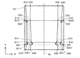
顔領域FAの傾き調整終了後のステップS530(図15)では、変形領域設定部240(図1)が、変形領域TAを設定する。変形領域TAは、対象画像TI上の領域であって顔形状補正のための画像変形処理の対象となる領域である。図27は、変形領域TAの設定方法の一例を示す説明図である。図27に示すように、本実施例では、変形領域TAは、顔領域FAを基準線RLと平行な方向(高さ方向)および基準線RLに直行する方向(幅方向)に伸張(または短縮)した領域として設定される。具体的には、顔領域FAの高さ方向の大きさをHf、幅方向の大きさをWfとすると、顔領域FAを、上方向にk1・Hf、下方向にk2・Hfだけ伸ばすと共に、左右にそれぞれk3・Wfだけ伸ばした領域が、変形領域TAとして設定される。なお、k1,k2,k3は、所定の係数である。 In step S530 (FIG. 15) after completion of the inclination adjustment of the face area FA, the deformation area setting unit 240 (FIG. 1) sets the deformation area TA. The deformation area TA is an area on the target image TI and is an area to be subjected to image deformation processing for face shape correction. FIG. 27 is an explanatory diagram showing an example of a method for setting the deformation area TA. As shown in FIG. 27, in this embodiment, the deformation area TA extends (or shortens) the face area FA in a direction (height direction) parallel to the reference line RL and a direction (width direction) perpendicular to the reference line RL. ). Specifically, assuming that the size in the height direction of the face area FA is Hf and the size in the width direction is Wf, the face area FA is extended by k1 · Hf in the upward direction and k2 · Hf in the downward direction, A region extended by k3 · Wf to the left and right is set as the deformation region TA. Note that k1, k2, and k3 are predetermined coefficients.
このように変形領域TAが設定されると、顔領域FAの高さ方向の輪郭線に平行な直線である基準線RLは、変形領域TAの高さ方向の輪郭線にも平行な直線となる。また、基準線RLは、変形領域TAの幅を半分に分割する直線となる。 When the deformation area TA is set in this way, the reference line RL, which is a straight line parallel to the contour line in the height direction of the face area FA, becomes a straight line parallel to the contour line in the height direction of the deformation area TA. . The reference line RL is a straight line that divides the width of the deformation area TA in half.
図27に示すように、変形領域TAは、高さ方向に関しては、概ね顎から額までの画像を含み、幅方向に関しては、左右の頬の画像を含むような領域として設定される。すなわち、本実施例では、変形領域TAが概ねそのような範囲の画像を含む領域となるように、顔領域FAの大きさとの関係に基づき、上述の係数k1,k2,k3が予め設定されている。 As shown in FIG. 27, the deformation area TA is set as an area that generally includes an image from the jaw to the forehead in the height direction and includes images of the left and right cheeks in the width direction. That is, in this embodiment, the above-described coefficients k1, k2, and k3 are set in advance based on the relationship with the size of the face area FA so that the deformation area TA is an area that includes an image in such a range. Yes.
A−4.変形処理:
上述した顔形状補正処理(図4)における変形処理(ステップS600)について詳述する。図28は、変形処理の流れを示すフローチャートである。ステップS610では、変形領域分割部250(図1)が、変形領域TAを複数の小領域に分割する。図29は、変形領域TAの小領域への分割方法の一例を示す説明図である。変形領域分割部250は、変形領域TAに複数の分割点Dを配置し、分割点Dを結ぶ直線を用いて変形領域TAを複数の小領域に分割する。
A-4. Transformation process:
The deformation process (step S600) in the face shape correction process (FIG. 4) described above will be described in detail. FIG. 28 is a flowchart showing the flow of deformation processing. In step S610, the deformation area dividing unit 250 (FIG. 1) divides the deformation area TA into a plurality of small areas. FIG. 29 is an explanatory diagram showing an example of a method of dividing the deformation area TA into small areas. The deformation
分割点Dの配置の態様(分割点Dの個数および位置)は、分割点配置パターンテーブル410(図1)により、ステップS120(図4)において設定される変形タイプと対応付けて定義されている。変形領域分割部250は、分割点配置パターンテーブル410を参照し、ステップS120において設定された変形タイプと対応付けられた態様で分割点Dを配置する。本実施例では、上述したように、変形タイプとして顔をシャープにするための変形「タイプA」(図5参照)が設定されているため、この変形タイプに対応付けられた態様で分割点Dが配置される。
The arrangement mode of the dividing points D (the number and positions of the dividing points D) is defined in association with the deformation type set in step S120 (FIG. 4) by the dividing point arrangement pattern table 410 (FIG. 1). . The deformation
図29に示すように、分割点Dは、水平分割線Lhと垂直分割線Lvとの交点と、水平分割線Lhおよび垂直分割線Lvと変形領域TAの外枠との交点とに配置される。ここで、水平分割線Lhおよび垂直分割線Lvは、変形領域TA内に分割点Dを配置するための基準となる線である。図29に示すように、顔をシャープにするための変形タイプに対応付けられた分割点Dの配置では、基準線RLと直行する2本の水平分割線Lhと、基準線RLに平行な4本の垂直分割線Lvとが設定される。2本の水平分割線Lhを、変形領域TAの下方から順に、Lh1,Lh2と呼ぶ。また、4本の垂直分割線Lvを、変形領域TAの左から順に、Lv1,Lv2,Lv3,Lv4と呼ぶ。 As shown in FIG. 29, the division points D are arranged at the intersections of the horizontal division line Lh and the vertical division line Lv and the intersections of the horizontal division line Lh and the vertical division line Lv and the outer frame of the deformation area TA. . Here, the horizontal dividing line Lh and the vertical dividing line Lv are reference lines for arranging the dividing points D in the deformation area TA. As shown in FIG. 29, in the arrangement of the dividing points D associated with the deformation type for sharpening the face, two horizontal dividing lines Lh perpendicular to the reference line RL and 4 parallel to the reference line RL are used. A vertical division line Lv is set. The two horizontal dividing lines Lh are called Lh1 and Lh2 in order from the bottom of the deformation area TA. The four vertical dividing lines Lv are referred to as Lv1, Lv2, Lv3, and Lv4 in order from the left of the deformation area TA.
水平分割線Lh1は、変形領域TAにおいて、顎の画像より下方に配置され、水平分割線Lh2は、目の画像のすぐ下付近に配置される。また、垂直分割線Lv1およびLv4は、頬のラインの画像の外側に配置され、垂直分割線Lv2およびLv3は、目尻の画像の外側に配置される。なお、水平分割線Lhおよび垂直分割線Lvの配置は、水平分割線Lhおよび垂直分割線Lvと画像との位置関係が結果的に上述の位置関係となるように予め設定された変形領域TAの大きさとの対応関係に従い実行される。 The horizontal dividing line Lh1 is arranged below the chin image in the deformation area TA, and the horizontal dividing line Lh2 is arranged near the eye image. The vertical dividing lines Lv1 and Lv4 are arranged outside the cheek line image, and the vertical dividing lines Lv2 and Lv3 are arranged outside the eye corner image. The horizontal dividing line Lh and the vertical dividing line Lv are arranged in the deformation area TA set in advance so that the positional relationship between the horizontal dividing line Lh and the vertical dividing line Lv and the image becomes the above-described positional relationship as a result. It is executed according to the correspondence with the size.
上述した水平分割線Lhと垂直分割線Lvとの配置に従い、水平分割線Lhと垂直分割線Lvとの交点と、水平分割線Lhおよび垂直分割線Lvと変形領域TAの外枠との交点とに、分割点Dが配置される。図29に示すように、水平分割線Lhi(i=1または2)上に位置する分割点Dを、左から順に、D0i,D1i,D2i,D3i,D4i,D5iと呼ぶものとする。例えば、水平分割線Lh1上に位置する分割点Dは、D01,D11,D21,D31,D41,D51と呼ばれる。同様に、垂直分割線Lvj(j=1,2,3,4のいずれか)上に位置する分割点Dを、下から順に、Dj0,Dj1,Dj2,Dj3と呼ぶものとする。例えば、垂直分割線Lv1上に位置する分割点Dは、D10,D11,D12,D13と呼ばれる。 According to the arrangement of the horizontal dividing line Lh and the vertical dividing line Lv described above, the intersection of the horizontal dividing line Lh and the vertical dividing line Lv, and the intersection of the horizontal dividing line Lh and the vertical dividing line Lv and the outer frame of the deformation area TA In addition, the dividing point D is arranged. As shown in FIG. 29, division points D located on the horizontal division line Lhi (i = 1 or 2) are called D0i, D1i, D2i, D3i, D4i, and D5i in order from the left. For example, the dividing points D located on the horizontal dividing line Lh1 are called D01, D11, D21, D31, D41, D51. Similarly, the dividing points D located on the vertical dividing line Lvj (j = 1, 2, 3, 4) are called Dj0, Dj1, Dj2, Dj3 in order from the bottom. For example, the division points D located on the vertical division line Lv1 are called D10, D11, D12, and D13.
なお、図29に示すように、本実施例における分割点Dの配置は、基準線RLに対して対称の配置となっている。 Note that, as shown in FIG. 29, the arrangement of the dividing points D in the present embodiment is symmetrical with respect to the reference line RL.
変形領域分割部250は、配置された分割点Dを結ぶ直線(すなわち水平分割線Lhおよび垂直分割線Lv)により、変形領域TAを複数の小領域に分割する。本実施例では、図29に示すように、変形領域TAが15個の矩形の小領域に分割される。
The deformation
なお本実施例では、分割点Dの配置は、水平分割線Lhおよび垂直分割線Lvの本数および位置により定まるため、分割点配置パターンテーブル410は水平分割線Lhおよび垂直分割線Lvの本数および位置を定義していると言い換えることも可能である。 In the present embodiment, since the arrangement of the dividing points D is determined by the numbers and positions of the horizontal dividing lines Lh and the vertical dividing lines Lv, the dividing point arrangement pattern table 410 has the numbers and positions of the horizontal dividing lines Lh and the vertical dividing lines Lv. In other words, it is possible to define that
ステップS620(図28)では、分割領域変形部260(図1)が、対象画像TIの変形領域TAを対象とした画像の変形処理を行う。分割領域変形部260による変形処理は、ステップS610で変形領域TA内に配置された分割点Dの位置を移動して、小領域を変形することにより行われる。 In step S620 (FIG. 28), the divided region deformation unit 260 (FIG. 1) performs image deformation processing on the deformation region TA of the target image TI. The deformation process by the divided area deforming unit 260 is performed by moving the position of the dividing point D arranged in the deformed area TA in step S610 to deform the small area.
変形処理のための各分割点Dの位置の移動態様(移動方向および移動距離)は、分割点移動テーブル420(図1)により、ステップS120(図4)において設定される変形タイプと変形の度合いとの組み合わせに対応付けて、予め定められている。分割領域変形部260は、分割点移動テーブル420を参照し、ステップS120において設定された変形タイプと変形の度合いとの組み合わせに対応付けられた移動方向および移動距離で、分割点Dの位置を移動する。 The movement mode (movement direction and movement distance) of the position of each division point D for the deformation process is determined by the division type and the degree of deformation set in step S120 (FIG. 4) by the division point movement table 420 (FIG. 1). Are determined in advance in association with the combination. The divided region deformation unit 260 refers to the divided point movement table 420 and moves the position of the divided point D with the moving direction and moving distance associated with the combination of the deformation type and the degree of deformation set in step S120. To do.
変形タイプとして顔をシャープにするための変形「タイプA」(図5参照)が設定され、変形度合いとして程度「中」の度合いが設定されている場合には、これらの変形タイプおよび変形度合いの組み合わせに対応付けられた移動方向および移動距離で、分割点Dの位置が移動されることとなる。 When the deformation “type A” (see FIG. 5) for sharpening the face is set as the deformation type, and the degree of “medium” is set as the deformation degree, these deformation types and deformation degrees The position of the dividing point D is moved with the moving direction and moving distance associated with the combination.
また、変形度合いとして「自動」が選択されている場合には、分割点Dの移動方向および移動距離が、変形量設定部290によって設定された変形量DQに基づいて決定される。 When “automatic” is selected as the deformation degree, the moving direction and moving distance of the dividing point D are determined based on the deformation amount DQ set by the deformation amount setting unit 290.
図30は、分割点移動テーブル420の内容の一例を示す説明図である。また図31は、分割点移動テーブル420に従った分割点Dの位置の移動の一例を示す説明図である。図30には、分割点移動テーブル420により定義された分割点Dの位置の移動態様の内、顔をシャープにするための変形タイプと変形度合い「自動」との組み合わせに対応付けられた移動態様を示している。図30に示すように、分割点移動テーブル420には、各分割点Dについて、基準線RLと直交する方向(H方向)および基準線RLと平行な方向(V方向)に沿った移動量が示されている。なお、分割点移動テーブル420に示された移動量の単位は、対象画像TIの画素ピッチPPである。また、テーブル中の移動量DQpは、変形量設定部290(図1)によって決定される。図4のステップS590では、変形量設定部290は、設定した変形量DQを画素ピッチに換算することによって、移動量DQpを算出する。また、H方向については、向かって右側への移動量が正の値として表され、向かって左側への移動量が負の値として表され、V方向については、上方への移動量が正の値として表され、下方への移動量が負の値として表される。例えば、分割点D11は、H方向に沿って右側に画素ピッチPPのDQp倍の距離だけ移動され、V方向に沿って上方に画素ピッチPPの2*DQp倍の距離だけ移動される。また、例えば分割点D22は、H方向およびV方向共に移動量がゼロであるため、移動されない。なお、変形度合いとして「強(S)」、「中(M)」、「弱(W)」のいずれかが選択された場合には、移動量DQpとして、変形量設定部290によって調整された値の代わりに、各変形度合いに対応付けて予め定められた値が利用される。
FIG. 30 is an explanatory diagram showing an example of the contents of the dividing point movement table 420. As shown in FIG. FIG. 31 is an explanatory diagram showing an example of movement of the position of the dividing point D according to the dividing point movement table 420. FIG. 30 shows a movement mode associated with a combination of a deformation type for sharpening the face and a deformation degree “automatic” among the movement modes of the position of the division point D defined by the division point movement table 420. Is shown. As shown in FIG. 30, in the dividing point moving table 420, for each dividing point D, the moving amount along the direction (H direction) orthogonal to the reference line RL and the direction parallel to the reference line RL (V direction) is displayed. It is shown. Note that the unit of movement amount shown in the dividing point movement table 420 is the pixel pitch PP of the target image TI. Further, the movement amount DQp in the table is determined by the deformation amount setting unit 290 (FIG. 1). In step S590 of FIG. 4, the deformation amount setting unit 290 calculates the movement amount DQp by converting the set deformation amount DQ into a pixel pitch. For the H direction, the amount of movement to the right side is represented as a positive value, the amount of movement to the left side is represented as a negative value, and for the V direction, the amount of movement upward is positive. It is expressed as a value, and the downward movement amount is expressed as a negative value. For example, the dividing point D11 is moved to the right along the H direction by a distance DQp times the pixel pitch PP, and moved upward along the V direction by a
なお、本実施例では、変形領域TAの内外の画像間の境界が不自然とならないように、変形領域TAの外枠上に位置する分割点D(例えば図29に示す分割点D10等)の位置は移動されないものとしている。従って、図30に示した分割点移動テーブル420には、変形領域TAの外枠上に位置する分割点Dについての移動態様は定義されていない。 In this embodiment, division points D (for example, division points D10 shown in FIG. 29, etc.) located on the outer frame of the deformation area TA are set so that the boundary between the inner and outer images of the deformation area TA does not become unnatural. The position is not moved. Therefore, in the division point movement table 420 shown in FIG. 30, the movement mode for the division point D located on the outer frame of the deformation area TA is not defined.
図31では、移動前の分割点Dは白抜きの丸で、移動後の分割点Dや位置の移動の無い分割点Dは黒丸で示されている。また、移動後の分割点Dは分割点D'と呼ばれるものとする。例えば分割点D11の位置は、図31において右上方向に移動され、分割点D'11となる。 In FIG. 31, the division point D before the movement is indicated by a white circle, and the division point D after the movement or the division point D without the movement of the position is indicated by a black circle. The divided point D after the movement is called a divided point D ′. For example, the position of the dividing point D11 is moved in the upper right direction in FIG. 31, and becomes the dividing point D′ 11.
なお、本実施例では、基準線RLに対して対称な位置関係にある2つの分割点Dの組み合わせ(例えば分割点D11とD41との組み合わせ)のすべてが、分割点Dの移動後も、基準線RLに対して対称な位置関係を維持するように、移動態様が定められている。 In the present embodiment, all combinations of two division points D (for example, combinations of division points D11 and D41) that are in a symmetric positional relationship with respect to the reference line RL are the same after the movement of the division point D. The movement mode is determined so as to maintain a symmetrical positional relationship with respect to the line RL.
分割領域変形部260は、変形領域TAを構成する各小領域について、分割点Dの位置移動前の状態における小領域の画像が、分割点Dの位置移動により新たに定義された小領域の画像となるように、画像の変形処理を行う。例えば、図31において、分割点D11,D21,D22,D12を頂点とする小領域(ハッチングを付して示す小領域)の画像は、分割点D'11,D'21,D22,D'12を頂点とする小領域の画像に変形される。 For each small area constituting the deformation area TA, the divided area deforming unit 260 is an image of a small area newly defined by moving the position of the dividing point D. The image is deformed so that For example, in FIG. 31, the image of the small area (small area shown with hatching) having the vertexes at the dividing points D11, D21, D22, and D12 is divided into the dividing points D′ 11, D′ 21, D22, and D′ 12. Is transformed into an image of a small area with the vertex at.
図32は、分割領域変形部260による画像の変形処理方法の概念を示す説明図である。図32では、分割点Dを黒丸で示している。図32では、説明を簡略化するために、4つの小領域について、左側に分割点Dの位置移動前の状態を、右側に分割点Dの位置移動後の状態を、それぞれ示している。図32の例では、中央の分割点Daが分割点Da'の位置に移動され、その他の分割点Dの位置は移動されない。これにより、例えば、分割点Dの移動前の分割点Da,Db,Dc,Ddを頂点とする矩形の小領域(以下「変形前注目小領域BSA」とも呼ぶ)の画像は、分割点Da',Db,Dc,Ddを頂点とする矩形の小領域(以下「変形後注目小領域ASA」とも呼ぶ)の画像に変形される。 FIG. 32 is an explanatory diagram showing the concept of the image deformation processing method by the divided region deformation unit 260. In FIG. 32, the dividing point D is indicated by a black circle. In FIG. 32, for simplification of description, the state before the position movement of the dividing point D is shown on the left side and the state after the position movement of the dividing point D is shown on the right side for the four small areas. In the example of FIG. 32, the center division point Da is moved to the position of the division point Da ′, and the positions of the other division points D are not moved. Thereby, for example, an image of a rectangular small area (hereinafter also referred to as “pre-deformation noticeable small area BSA”) having the vertices at the division points Da, Db, Dc, Dd before the movement of the division point D is obtained from the division point Da ′. , Db, Dc, and Dd are transformed into an image of a rectangular small area (hereinafter also referred to as “the noticed small area ASA after deformation”).
本実施例では、矩形の小領域を小領域の重心CGを用いて4つの三角形領域に分割し、三角形領域単位で画像の変形処理を行っている。図32の例では、変形前注目小領域BSAが、変形前注目小領域BSAの重心CGを頂点の1つとする4つの三角形領域に分割される。同様に、変形後注目小領域ASAが、変形後注目小領域ASAの重心CG'を頂点の1つとする4つの三角形領域に分割される。そして、分割点Daの移動前後のそれぞれの状態において対応する三角形領域毎に、画像の変形処理が行われる。例えば、変形前注目小領域BSA中の分割点Da,Ddおよび重心CGを頂点とする三角形領域の画像が、変形後注目小領域ASA中の分割点Da',Ddおよび重心CG'を頂点とする三角形領域の画像に変形される。 In this embodiment, a rectangular small region is divided into four triangular regions using the center of gravity CG of the small region, and image deformation processing is performed in units of triangular regions. In the example of FIG. 32, the pre-deformation attention small area BSA is divided into four triangular areas having the centroid CG of the pre-deformation attention small area BSA as one vertex. Similarly, the post-deformation attention small area ASA is divided into four triangular areas having the centroid CG ′ of the post-deformation attention small area ASA as one vertex. Then, image deformation processing is performed for each corresponding triangular area in each state before and after the movement of the dividing point Da. For example, an image of a triangular area having vertices at the division points Da and Dd and the center of gravity CG in the attention small area BSA before deformation has a vertex at the division points Da ′ and Dd and the center of gravity CG ′ in the attention small area ASA after deformation. It is transformed into an image of a triangular area.
図33は、三角形領域における画像の変形処理方法の概念を示す説明図である。図33の例では、点s,t,uを頂点とする三角形領域stuの画像が、点s',t',u'を頂点とする三角形領域s't'u'の画像に変形される。画像の変形は、変形後の三角形領域s't'u'の画像中のある画素の位置が、変形前の三角形領域stuの画像中のどの位置に相当するかを算出し、算出された位置における変形前の画像における画素値を変形後の画像の画素値とすることにより行う。 FIG. 33 is an explanatory diagram showing the concept of an image deformation processing method in a triangular area. In the example of FIG. 33, the image of the triangular area stu with the points s, t, u as vertices is transformed into the image of the triangular area s′t′u ′ with the points s ′, t ′, u ′ as vertices. . For the deformation of the image, the position of a certain pixel in the image of the triangular area s't'u 'after the deformation corresponds to the position in the image of the triangular area stu before the deformation, and the calculated position This is performed by using the pixel value in the image before deformation in step S4 as the pixel value of the image after deformation.
例えば、図33において、変形後の三角形領域s't'u'の画像中の注目画素p'の位置は、変形前の三角形領域stuの画像中の位置pに相当するものとする。位置pの算出は、以下のように行う。まず、注目画素p'の位置を、下記の式(4)のようにベクトルs't'とベクトルs'u'との和で表現するための係数m1およびm2を算出する。 For example, in FIG. 33, the position of the pixel of interest p ′ in the image of the triangular area s′t′u ′ after deformation corresponds to the position p in the image of the triangular area stu before deformation. The position p is calculated as follows. First, coefficients m1 and m2 for expressing the position of the pixel of interest p ′ as a sum of a vector s′t ′ and a vector s′u ′ as shown in the following equation (4) are calculated.

次に、算出された係数m1およびm2を用いて、下記の式(5)により、変形前の三角形領域stuにおけるベクトルstとベクトルsuとの和を算出することにより、位置pが求まる。 Next, by using the calculated coefficients m1 and m2, the position p is obtained by calculating the sum of the vector st and the vector su in the triangular area stu before deformation according to the following equation (5).
![]()
![]()
変形前の三角形領域stuにおける位置pが、変形前の画像の画素中心位置に一致した場合には、当該画素の画素値が変形後の画像の画素値とされる。一方、変形前の三角形領域stuにおける位置pが、変形前の画像の画素中心位置からはずれた位置となった場合には、位置pの周囲の画素の画素値を用いたバイキュービック等の補間演算により、位置pにおける画素値を算出し、算出された画素値が変形後の画像の画素値とされる。 When the position p in the triangular area stu before deformation coincides with the pixel center position of the image before deformation, the pixel value of the pixel is set as the pixel value of the image after deformation. On the other hand, when the position p in the triangular area stu before deformation is shifted from the pixel center position of the image before deformation, an interpolation operation such as bicubic using the pixel values of the pixels around the position p. Thus, the pixel value at the position p is calculated, and the calculated pixel value is set as the pixel value of the image after deformation.
変形後の三角形領域s't'u'の画像中の各画素について上述のように画素値を算出することにより、三角形領域stuの画像から三角形領域s't'u'の画像への画像変形処理を行うことができる。分割領域変形部260は、図31に示した変形領域TAを構成する各小領域について、上述したように三角形領域を定義して変形処理を行い、変形領域TAにおける画像変形処理を行う。 Image deformation from the image of the triangular area stu to the image of the triangular area s't'u 'by calculating the pixel value for each pixel in the image of the triangular area s't'u' after the deformation as described above Processing can be performed. The divided area deformation unit 260 performs a deformation process by defining a triangular area as described above for each small area constituting the deformation area TA shown in FIG. 31, and performs an image deformation process in the deformation area TA.
ここで、変形タイプとして顔をシャープにするための変形「タイプA」(図5参照)が設定され、変形度合いとして「自動」が設定された場合を例に取り、顔形状補正の態様についてより詳細に説明する。図34は、この場合における顔形状補正の態様を示す説明図である。図34には、変形領域TAを構成する各小領域の変形態様のイメージを矢印により示している。 Here, a case where the deformation “type A” (see FIG. 5) for sharpening the face is set as the deformation type and “automatic” is set as the deformation degree will be taken as an example. This will be described in detail. FIG. 34 is an explanatory diagram showing a form of face shape correction in this case. In FIG. 34, the image of the deformation | transformation aspect of each small area | region which comprises deformation | transformation area | region TA is shown with the arrow.
図34の例に示す顔形状補正では、基準線RLと平行な方向(V方向)に関し、水平分割線Lh1上に配置された分割点D(D11,D21,D31,D41)の位置は上方に移動される一方、水平分割線Lh2上に配置された分割点D(D12,D22,D32,D42)の位置は移動されない(図30参照)。従って、水平分割線Lh1と水平分割線Lh2との間に位置する画像は、V方向に関して縮小される。上述したように、水平分割線Lh1は顎の画像より下方に配置され、水平分割線Lh2は目の画像のすぐ下付近に配置されるため、この顔形状補正では、顔の画像の内、顎から目の下にかけての部分の画像がV方向に縮小されることとなる。この結果、画像中の顎のラインは上方に移動する。 In the face shape correction shown in the example of FIG. 34, the position of the dividing point D (D11, D21, D31, D41) arranged on the horizontal dividing line Lh1 is upward in the direction (V direction) parallel to the reference line RL. On the other hand, the position of the dividing point D (D12, D22, D32, D42) arranged on the horizontal dividing line Lh2 is not moved (see FIG. 30). Therefore, the image located between the horizontal dividing line Lh1 and the horizontal dividing line Lh2 is reduced in the V direction. As described above, since the horizontal dividing line Lh1 is disposed below the jaw image and the horizontal dividing line Lh2 is disposed near the lower part of the eye image, in this face shape correction, in the face image, the jaw The image of the part from the eye to the bottom of the eye is reduced in the V direction. As a result, the jaw line in the image moves upward.
他方、基準線RLと直交する方向(H方向)に関しては、垂直分割線Lv1上に配置された分割点D(D11,D12)の位置は右方向に移動され、垂直分割線Lv4上に配置された分割点D(D41,D42)の位置は左方向に移動される(図30参照)。さらに、垂直分割線Lv2上に配置された2つの分割点Dの内、水平分割線Lh1上に配置された分割点D(D21)の位置は右方向に移動され、垂直分割線Lv3上に配置された2つの分割点Dの内、水平分割線Lh1上に配置された分割点D(D31)の位置は左方向に移動される(図30参照)。従って、垂直分割線Lv1より左側に位置する画像は、H方向に関して右側に拡大され、垂直分割線Lv4より右側に位置する画像は、左側に拡大される。また、垂直分割線Lv1と垂直分割線Lv2との間に位置する画像は、H方向に関して縮小または右側に移動され、垂直分割線Lv3と垂直分割線Lv4との間に位置する画像は、H方向に関して縮小または左側に移動される。さらに、垂直分割線Lv2と垂直分割線Lv3との間に位置する画像は、水平分割線Lh1の位置を中心にH方向に関して縮小される。 On the other hand, regarding the direction (H direction) orthogonal to the reference line RL, the position of the dividing point D (D11, D12) arranged on the vertical dividing line Lv1 is moved rightward and arranged on the vertical dividing line Lv4. The position of the divided point D (D41, D42) is moved to the left (see FIG. 30). Further, of the two division points D arranged on the vertical division line Lv2, the position of the division point D (D21) arranged on the horizontal division line Lh1 is moved rightward and arranged on the vertical division line Lv3. Of the two divided points D, the position of the divided point D (D31) arranged on the horizontal dividing line Lh1 is moved to the left (see FIG. 30). Therefore, the image located on the left side of the vertical dividing line Lv1 is enlarged on the right side in the H direction, and the image located on the right side of the vertical dividing line Lv4 is enlarged on the left side. An image located between the vertical dividing line Lv1 and the vertical dividing line Lv2 is reduced or moved to the right in the H direction, and an image located between the vertical dividing line Lv3 and the vertical dividing line Lv4 is moved in the H direction. Is reduced or moved to the left. Further, the image located between the vertical division line Lv2 and the vertical division line Lv3 is reduced in the H direction with the position of the horizontal division line Lh1 as the center.
上述したように、垂直分割線Lv1およびLv4は、頬のラインの画像の外側に配置され、垂直分割線Lv2およびLv3は、目尻の画像の外側に配置される。そのため、図34の例における顔形状補正では、顔の画像の内、両目尻より外側の部分の画像が全体的にH方向に縮小される。特に顎付近において縮小率が高くなる。この結果、画像中の顔の形状は、全体的に幅方向に細くなる。 As described above, the vertical division lines Lv1 and Lv4 are arranged outside the cheek line image, and the vertical division lines Lv2 and Lv3 are arranged outside the corner image. Therefore, in the face shape correction in the example of FIG. 34, the image of the portion outside the both corners of the face image is reduced in the H direction as a whole. In particular, the reduction rate is high near the jaw. As a result, the shape of the face in the image becomes thinner in the width direction as a whole.
上述したH方向およびV方向の変形態様を総合すると、図34の例に示した顔形状補正により、対象画像TI中の顔の形状がシャープになる。なお、顔の形状がシャープになるとは、いわゆる「小顔」になると表現することもできる。 When the deformation modes in the H direction and the V direction described above are combined, the face shape in the target image TI is sharpened by the face shape correction shown in the example of FIG. Note that a sharp face shape can be expressed as a so-called “small face”.
なお、図34に示す分割点D22,D32,D33,D23を頂点とする小領域(ハッチングを付した領域)は、上述した水平分割線Lh2や垂直分割線Lv2およびLv3の配置方法によると、両目の画像を含む領域となる。図30に示すように、分割点D22およびD32はH方向にもV方向にも移動されないため、この両目の画像を含む小領域は変形されない。このように図34の例では、両目の画像を含む小領域については変形しないこととし、顔形状補正後の画像がより自然で好ましいものとなるようにしている。 Note that the small areas (hatched areas) having the divide points D22, D32, D33, and D23 shown in FIG. 34 as the apexes are determined according to the arrangement method of the horizontal division lines Lh2 and the vertical division lines Lv2 and Lv3. This area includes the image. As shown in FIG. 30, since the dividing points D22 and D32 are not moved in the H direction or the V direction, the small region including the images of both eyes is not deformed. As described above, in the example of FIG. 34, the small region including the images of both eyes is not deformed, and the image after the face shape correction is made more natural and preferable.
A−5.他の変形処理:
図35は、変形処理の他の実施例を示す概略図である。図9に示す変形処理とは異なり、図35の例では、対象画像TI上の一部の変形領域が変形される代わりに、対象画像TIの全体のアスペクト比が変更される。
A-5. Other transformations:
FIG. 35 is a schematic view showing another embodiment of the deformation process. Unlike the deformation process shown in FIG. 9, in the example of FIG. 35, the entire aspect ratio of the target image TI is changed instead of deforming a part of the deformation area on the target image TI.
図35(a)は、変形前の対象画像TIを示し、図35(b)は変形後の画像TIdを示している。また、図中には、互いに直交する2つの方向Dr1、Dr2が示されている。第1方向Dr1は、矩形画像TI、TIdの短辺と平行な方向を示し、第2方向Dr2は、矩形画像TI、TIdの長辺と平行な方向を示している。図35の例では、顔の幅方向は、第2方向Dr2とほぼ一致している。 FIG. 35A shows the target image TI before deformation, and FIG. 35B shows the image TId after deformation. In the figure, two directions Dr1 and Dr2 orthogonal to each other are shown. The first direction Dr1 indicates a direction parallel to the short sides of the rectangular images TI and TId, and the second direction Dr2 indicates a direction parallel to the long sides of the rectangular images TI and TId. In the example of FIG. 35, the face width direction substantially coincides with the second direction Dr2.
図35の例では、第1方向Dr1に沿った変形は実行されずに、第2方向Dr2に沿った変形(圧縮)が実行される。この変形によって、画像の全体が、第2方向Dr2に沿って圧縮される。すなわち、対象画像TI上の被写体の幅も狭くなる。その結果、画像の観察によって得られる被写体の印象を、実物の観察によって得られる印象に近づけることができる。 In the example of FIG. 35, the deformation (compression) along the second direction Dr2 is performed without performing the deformation along the first direction Dr1. By this deformation, the entire image is compressed along the second direction Dr2. That is, the width of the subject on the target image TI is also narrowed. As a result, the impression of the subject obtained by observing the image can be brought close to the impression obtained by observing the real object.
この変形では、変形済画像TIdの第2方向Dr2の大きさ(幅IWd)が、変形前の大きさ(幅IW)と比べて、変形量DQの2倍だけ小さくなる。すなわち、変形済画像TIdの第2方向Dr2方向の画素数が、変形前の画素数と比べて、少なくなる。ここで、変形済画像TIdの画素値(各画素の階調値)の決定方法としては、種々の方法を採用可能である。例えば、対象画像TIの画素値を補間することによって、変形済画像TIdの画素値を決定してもよい。 In this deformation, the size (width IWd) of the deformed image TId in the second direction Dr2 is smaller by twice the deformation amount DQ than the size (width IW) before the deformation. That is, the number of pixels in the second direction Dr2 direction of the deformed image TId is smaller than the number of pixels before the deformation. Here, various methods can be adopted as a method of determining the pixel value (gradation value of each pixel) of the deformed image TId. For example, the pixel value of the transformed image TId may be determined by interpolating the pixel value of the target image TI.
変形量DQとしては、上述の実施例で説明した任意の変形量を採用可能である。例えば、被写体距離Sdに基づいて決定された変形量DQを採用してもよい。 As the deformation amount DQ, any deformation amount described in the above embodiment can be adopted. For example, the deformation amount DQ determined based on the subject distance Sd may be employed.
なお、2つの方向Dr1、Dr2から圧縮すべき方向を、被写体の方向の検出結果に基づいて選択することが好ましい。例えば、顔領域検出部220(図1)は、図14、図35(a)に示すように、顔領域FAの高さ方向(上下方向)を示す基準線RLを検出可能である。そこで、2つの方向Dr1、Dr2の内の、この基準線RLとのなす角度が大きい方の方向を選択することが好ましい(図35の例では、第2方向Dr2)。こうすば、被写体の幅(水平方向の大きさ)を小さくすることができる。 It is preferable to select a direction to be compressed from the two directions Dr1 and Dr2 based on the detection result of the direction of the subject. For example, the face area detection unit 220 (FIG. 1) can detect the reference line RL indicating the height direction (vertical direction) of the face area FA, as shown in FIGS. Therefore, it is preferable to select the direction of the two directions Dr1 and Dr2 that has a larger angle with the reference line RL (second direction Dr2 in the example of FIG. 35). In this way, the width (horizontal size) of the subject can be reduced.
なお、対象画像TIの全体のアスペクト比を変更する変形処理を採用する場合には、顔形状補正部として、図1に示すような顔形状補正部200を採用可能である。ただし、変形処理部から、変形領域分割部250と分割領域変形部260とを省略することができる。その代わりに、変形処理部は、対象画像TIのアスペクト比を変更する機能を有していればよい。また、顔領域調整部230と変形領域設定部240とを省略可能である。顔領域検出部220は、被写体の方向を検出するために利用され得る。ただし、顔領域検出部220を省略してもよい。
Note that when a deformation process that changes the overall aspect ratio of the target image TI is employed, a face
ここで、被写体の幅方向に沿って対象画像TIを圧縮する変形処理の代わりに、被写体の高さ方向に沿って対象画像TIを伸張する変形処理を採用してもよい。この場合も、被写体の高さに対する幅の比率が小さくなるので、画像の観察によって得られる被写体の印象を、実物の観察によって得られる印象に近づけることができる。 Here, instead of the deformation process for compressing the target image TI along the width direction of the subject, a deformation process for expanding the target image TI along the height direction of the subject may be employed. Also in this case, since the ratio of the width to the height of the subject becomes small, the impression of the subject obtained by observing the image can be made closer to the impression obtained by observing the real object.
B.第2実施例:
図36は、本発明の第2実施例における画像処理装置としてのプリンタ100aの構成を概略的に示す説明図である。第2実施例のプリンタ100aと第1実施例のプリンタ100(図1)との違いは、第2実施例のプリンタ100aが顔形状補正部200の代わりにぼかし処理部360を備えている点である。第2実施例のプリンタ100aのその他の構成は、第1実施例のプリンタ100と同様である。
B. Second embodiment:
FIG. 36 is an explanatory diagram schematically showing the configuration of a
ぼかし処理部360は、所定のオペレーティングシステムの下で、後述する背景ぼかし印刷処理を実行するためのコンピュータプログラムである。ぼかし処理部360は、ぼかし度合い設定部362を含んでいる。
The
図37は、第2実施例のプリンタ100aによる背景ぼかし印刷処理の流れを示すフローチャートである。背景ぼかし印刷処理は、対象画像中の背景領域の画像にぼかし処理を施した後、印刷を行う処理である。背景ぼかし印刷処理により、遠近感が大きく、主な被写体が強調された画像の印刷を実現できる。
FIG. 37 is a flowchart illustrating the flow of background blur printing processing performed by the
ステップS710では、ぼかし処理部360(図36)が、背景ぼかし印刷処理の対象画像TIaを設定する。対象画像TIaの設定方法は、第1実施例の顔形状補正処理(図4)における対象画像の設定方法と同様である。図38は、背景ぼかし印刷処理の対象画像TIaの一例を示す説明図である。 In step S710, the blur processing unit 360 (FIG. 36) sets the target image TIa for the background blur printing process. The setting method of the target image TIa is the same as the setting method of the target image in the face shape correction process (FIG. 4) of the first embodiment. FIG. 38 is an explanatory diagram showing an example of the target image TIa for the background blur printing process.
ステップS720(図37)では、顔領域検出部220(図36)が、対象画像TIaにおける顔領域FAを検出する。顔領域FAの検出方法は、第1実施例の顔形状補正処理(図4)における顔領域FAの検出方法と同様である。図38には、対象画像TIaにおける検出された顔領域FAを破線で示している。 In step S720 (FIG. 37), the face area detection unit 220 (FIG. 36) detects the face area FA in the target image TIa. The method for detecting the face area FA is the same as the method for detecting the face area FA in the face shape correction process (FIG. 4) of the first embodiment. In FIG. 38, the detected face area FA in the target image TIa is indicated by a broken line.
ステップS730(図37)では、ぼかし処理部360が、背景領域を設定する。背景領域は、対象画像TIaにおけるぼかし処理を施す領域である。ぼかし処理部360は、ステップS720で検出された顔領域FAに基づき除外領域EAを設定し、対象画像TIaにおける除外領域EAを除く領域を背景領域として設定する。図38には、対象画像TIaにおける設定された除外領域EAの一例を示している。除外領域EAの設定は、第1実施例の顔形状補正処理(図4)における変形領域TAの設定と同様に、顔領域FAを所定の係数を用いて拡大することにより行うことができる。なお図38に示すように、除外領域EAは、おおむね顔全体の画像を含む領域となるように、第1実施例における変形領域TA(図7参照)より大きな領域として設定されてもよい。また、除外領域EAは、おおむね人物の全身の画像を丸ごと含む領域となるように設定されてもよい。
In step S730 (FIG. 37), the blurring
ステップS740(図37)では、被写体距離推定部330(図36)が、被写体距離Sdを推定する。被写体距離Sdの推定方法は、第1実施例の顔形状補正処理(図4)における被写体距離Sdの推定方法と同様である。 In step S740 (FIG. 37), the subject distance estimation unit 330 (FIG. 36) estimates the subject distance Sd. The method for estimating the subject distance Sd is the same as the method for estimating the subject distance Sd in the face shape correction process (FIG. 4) of the first embodiment.
ステップS750(図37)では、ぼかし度合い設定部362(図36)が、ぼかし度合い(「ぼかし強度」とも呼ぶ)を設定する。ぼかし度合いは、対象画像TIa中の背景領域に施すぼかし処理の度合い(強度)である。ぼかし度合い設定部362は、予め定められたぼかし度合いと被写体距離Sdとの関係に基づき、ぼかし度合いを設定する。図39は、ぼかし度合いと被写体距離Sdとの関係を示すグラフである。横軸は被写体距離Sdを示し、縦軸はぼかし度合いを示している。図39に示すように、ぼかし度合いと被写体距離Sdとの関係は、被写体距離Sdが小さいほどぼかし度合いが大きくなるように定められている。一般の撮像装置では、撮像距離が短いほど被写界深度が浅くなる。従って、ぼかし度合いと被写体距離Sdとの関係を図39に示すように定めることにより、自然で好ましいぼかし処理が実現される。ぼかし度合い設定部362は、ステップS740で推定された被写体距離Sdと図39に示した関係とに基づき、ぼかし度合いを設定する。
In step S750 (FIG. 37), the blur level setting unit 362 (FIG. 36) sets the blur level (also referred to as “blur strength”). The degree of blurring is the degree (intensity) of blurring processing performed on the background area in the target image TIa. The blur
ステップS760(図37)では、ぼかし処理部360(図36)がぼかし処理を行う。ぼかし処理部360は、対象画像TIa中に設定された背景領域の画像に対し、ステップS750で設定されたぼかし度合いでぼかし処理を行う。なお、ぼかし処理は、例えばガウスフィルタを用いた公知の方法により実行される。図40は、ぼかし処理後の対象画像TIaの一例を示す説明図である。図40(a)には、被写体距離Sdが比較的小さい場合におけるぼかし処理後の対象画像TIaを示しており、図40(b)には、被写体距離Sdが比較的大きい場合におけるぼかし処理後の対象画像TIaを示している。図40(a)および図40(b)に示すように、被写体距離Sdが小さい方が、背景の画像のぼけ具合が大きくなる。
In step S760 (FIG. 37), the blurring processing unit 360 (FIG. 36) performs the blurring process. The blurring
その後、ぼかし処理後の画像の表示(図37のステップS770)および印刷(図37のステップS780)が実行される。ぼかし処理後の画像の表示および印刷は、第1実施例の顔形状補正印刷処理(図3)における画像の表示および印刷と同様に行われる。 Thereafter, display of the image after blurring (step S770 in FIG. 37) and printing (step S780 in FIG. 37) are executed. The display and printing of the image after the blurring process is performed in the same manner as the display and printing of the image in the face shape correction printing process (FIG. 3) of the first embodiment.
以上説明したように、第2実施例のプリンタ100aでは、推定された被写体距離Sdに基づき、被写体距離Sdが小さいほどぼかし度合いが大きくなるようにぼかし度合いが設定され、設定されたぼかし度合いを利用して画像のぼかし処理が行われる。そのため、撮像装置の特性に適合した自然で好ましい画像のぼかし処理を実現することができる。
As described above, in the
なお、本実施例における画像のぼかし処理は、本発明における特定の処理に相当し、本実施例において画像のぼかし処理を行うぼかし処理部360は本発明における特定処理実行部に相当する。
Note that the blurring process of the image in the present embodiment corresponds to a specific process in the present invention, and the
C.第3実施例:
図41は、本発明の第3実施例における画像処理装置としてのデジタルスチルカメラ500の構成を概略的に示す説明図である。第3実施例のデジタルスチルカメラ(以下「DSC」とも呼ぶ)500は、対象物を撮像して画像を生成する撮像装置(画像生成装置)として機能すると共に、生成された画像に対する画像処理を行う画像処理装置としても機能する。
C. Third embodiment:
FIG. 41 is an explanatory diagram schematically showing a configuration of a digital
DSC500は、レンズ502と、レンズ502を駆動して焦点(ピント)の位置や焦点距離を調整するレンズ駆動部504と、レンズ駆動部504を制御するレンズ駆動制御部506と、レンズ502を介して受光面に入力された光を電気信号に変換する撮像素子508と、撮像素子508から出力された電気信号に対するA/D変換を行うA/D変換器510と、外部機器との情報のやり取りのためのインターフェイス部(I/F部)512と、液晶ディスプレイにより構成された表示部514と、ボタンやタッチパネルにより構成された操作部516と、DSC500の各部を制御するCPU518と、ROMやRAMによって構成された内部メモリ600と、を備えている。撮像素子508は、例えばCCDを用いて構成される。DSC500の各構成要素は、バス522を介して互いに接続されている。
The
内部メモリ600には、画像生成部610が格納されている。画像生成部610は、所定のオペレーティングシステムの下で、後述する画像生成処理を実行するためのコンピュータプログラムである。CPU518は、内部メモリ600から、このプログラムを読み出して実行することにより、画像生成部610の機能を実現する。
The
画像生成部610は、プログラムモジュールとして、顔領域検出部620と、被写体距離推定部630と、画像ファイル生成部650と、焦点範囲設定部660と、タイミング決定部670とを含んでいる。また、被写体距離推定部630は、情報取得部640を含んでいる。これらの各部の機能については、後述の画像生成処理の説明において詳述する。なお、顔領域検出部620は、第1実施例のプリンタ100(図1)に含まれる顔領域検出部220と同様の機能を有し、被写体距離推定部630は、第1実施例のプリンタ100に含まれる被写体距離推定部330と同様の機能を有する。
The
図42は、第3実施例のDSC500による画像生成処理の流れを示すフローチャートである。第3実施例における画像生成処理では、所定の条件が満たされた場合に撮像が行われ、画像を表す画像データを含む画像ファイルが生成される。
FIG. 42 is a flowchart illustrating a flow of image generation processing by the
ステップS810では、画像生成部610(図41)が、準備画像を取得する。撮像前の種々の処理に用いられる画像である。画像生成部610は、レンズ502や撮像素子508、A/D変換器510を制御して、準備画像を取得する。なお、表示部514が撮像時のファインダーとして利用されている場合には、準備画像が表示部514に表示される。
In step S810, the image generation unit 610 (FIG. 41) acquires a preparation image. It is an image used for various processes before imaging. The
ステップS820(図42)では、顔領域検出部620(図41)が、準備画像における顔領域FAを検出する。顔領域FAの検出方法は、第1実施例の顔形状補正処理(図4)における顔領域FAの検出方法と同様である。 In step S820 (FIG. 42), the face area detection unit 620 (FIG. 41) detects the face area FA in the preparation image. The method for detecting the face area FA is the same as the method for detecting the face area FA in the face shape correction process (FIG. 4) of the first embodiment.
ステップS830(図42)では、被写体距離推定部630(図41)が、準備画像における被写体距離Sdを推定する。被写体距離Sdの推定方法は、第1実施例の顔形状補正処理(図4)における被写体距離Sdの推定方法と同様である。すなわち、情報取得部640が準備画像の全体の幅、顔領域FAの幅、人物Pの顔の幅、レンズの焦点距離、結像面の幅といった情報を取得し、被写体距離推定部630がこれらの情報と上記式(3)とを用いて被写体距離Sdを算出(推定)する。
In step S830 (FIG. 42), the subject distance estimation unit 630 (FIG. 41) estimates the subject distance Sd in the preparation image. The method for estimating the subject distance Sd is the same as the method for estimating the subject distance Sd in the face shape correction process (FIG. 4) of the first embodiment. That is, the information acquisition unit 640 acquires information such as the entire width of the prepared image, the width of the face area FA, the width of the face of the person P, the focal length of the lens, and the width of the imaging plane, and the subject
ステップS840(図43)では、タイミング決定部670(図41)が、ステップS830において推定された被写体距離Sdに基づき、画像生成タイミング(撮像タイミング)を決定する。図43は、第3実施例における画像生成処理の概要を示す説明図である。第3実施例における画像生成処理では、画像の生成(撮像)を行う条件として、被写体距離Sdが所定の閾値T1以下であるという条件が定められている。すなわち、図43において被写体としての人物Pが位置P2に居るときは、上記撮像条件が満たされず、撮像は行われない。一方、人物が位置P1に移動すると、上記撮像条件が満たされ、撮像が行われることとなる。なお、このような撮像条件は、例えば防犯カメラの撮像条件として設定されうる。 In step S840 (FIG. 43), the timing determination unit 670 (FIG. 41) determines the image generation timing (imaging timing) based on the subject distance Sd estimated in step S830. FIG. 43 is an explanatory diagram showing an overview of image generation processing in the third embodiment. In the image generation process in the third embodiment, a condition that the subject distance Sd is equal to or less than a predetermined threshold T1 is set as a condition for generating (imaging) an image. That is, in FIG. 43, when the person P as the subject is at the position P2, the imaging condition is not satisfied, and imaging is not performed. On the other hand, when the person moves to the position P1, the above imaging condition is satisfied and imaging is performed. Such an imaging condition can be set as an imaging condition of a security camera, for example.
ステップS840において、タイミング決定部670は、被写体距離Sdと閾値T1とを比較し、被写体距離Sdが閾値T1以下である場合には、画像生成を行うことを決定し、処理をステップS850にすすめる。一方、タイミング決定部670は、被写体距離Sdが閾値T1より大きい場合には、画像生成を行わないことを決定し、処理をステップS810に戻す。図42のステップS810からS840までの処理は、ステップS840において画像生成を行うことが決定されるまで、所定時間経過毎に繰り返し実行される。
In step S840, the
ステップS850(図42)では、焦点範囲設定部660(図41)が、ステップS830において推定された被写体距離Sdに基づき、焦点範囲FRを設定する。焦点範囲FRは、撮像時における焦点(ピント)の位置すべき範囲である。焦点範囲設定部660は、図43に示すように、DSC500から被写体距離Sdだけ離れた位置を中心として前後にそれぞれ所定の距離L1の広がりを有する範囲を焦点範囲FRとして設定する。なお、焦点範囲FRは、DSC500の機構上、焦点が位置することができる最大の範囲である最大焦点範囲FRmaxよりも狭い範囲として設定される。
In step S850 (FIG. 42), the focus range setting unit 660 (FIG. 41) sets the focus range FR based on the subject distance Sd estimated in step S830. The focal range FR is a range where the focal point (focus) should be located at the time of imaging. As shown in FIG. 43, the focus
ステップS860(図42)では、画像生成部610(図41)が、レンズ502、レンズ駆動部504、レンズ駆動制御部506を制御して、自動焦点合わせ(オートフォーカス)を行う。具体的には、画像生成部610は、焦点範囲FR内で焦点を移動させつつ撮像により画像を取得し、取得された画像の内のコントラストが最も大きい画像に対応した位置に焦点を合わせる。一般のDSCにおける自動焦点合わせでは、最大焦点範囲FRmax内で焦点を移動させつつ取得された画像のコントラスト検出が行われる。一方、本実施例のDSC500における自動焦点合わせでは、最大焦点範囲FRmaxよりも狭い範囲である焦点範囲FR内のみで焦点を移動させつつ取得された画像のコントラスト検出が行われるため、焦点合わせに要する時間の短縮を図ることができる。
In step S860 (FIG. 42), the image generation unit 610 (FIG. 41) controls the
ステップS870(図42)では、画像生成部610(図41)が、撮像により画像データを生成すると共に、画像ファイル生成部650が、画像データとステップS830において推定された被写体距離Sdを示すデータとを含む画像ファイルを生成する。画像ファイルは、例えばExif規格に則ったファイルとして生成され、被写体距離Sdを示すデータは、付加データとして画像ファイルに付加される。
In step S870 (FIG. 42), the image generation unit 610 (FIG. 41) generates image data by imaging, and the image
以上説明したように、第3実施例のDSC500による画像生成処理では、準備画像における被写体距離Sdの推定が行われ、推定された被写体距離Sdに基づき画像生成(撮像)タイミングが決定される。そのため、DSC500と被写体との距離に関する撮像条件を定めて画像の生成を行うことができる。また、第3実施例のDSC500による画像生成処理では、推定された被写体距離Sdに基づき、焦点範囲FRが設定され、焦点範囲FR内で自動焦点合わせが行われる。そのため、焦点合わせに要する時間の短縮を図ることができる。
As described above, in the image generation processing by the
また、第3実施例のDSC500による画像生成処理では、画像データと被写体距離Sdを示すデータとを含む画像ファイルが生成される。そのため、画像ファイル生成の後に、画像ファイルに含まれる被写体距離Sdを示すデータを利用して、第1実施例で説明した顔形状補正処理や第2実施例で説明したぼかし処理を行うことができる。また、画像ファイルに含まれる被写体距離Sdを示すデータは、画像の検索にも利用可能である。例えば、複数の画像ファイルの中から被写体距離Sdが比較的小さい画像を容易に選択することが可能となる。
In the image generation process by the
なお、本実施例における画像ファイルの生成、画像生成タイミングの決定および焦点範囲FRの設定は、それぞれ本発明における特定の処理に相当し、本実施例において画像ファイルの生成、画像生成タイミングの決定および焦点範囲FRの設定を行う画像ファイル生成部650、タイミング決定部670および焦点範囲設定部660は、それぞれ本発明における特定処理実行部に相当する。また、本実施例における準備画像は、本発明における対象画像に相当する。
The generation of the image file, the determination of the image generation timing, and the setting of the focus range FR in the present embodiment correspond to specific processing in the present invention, respectively. In the present embodiment, the generation of the image file, the determination of the image generation timing, The image
D.変形例:
なお、この発明は上記の実施例や実施形態に限られるものではなく、その要旨を逸脱しない範囲において種々の態様において実施することが可能であり、例えば次のような変形も可能である。
D. Variations:
The present invention is not limited to the above-described examples and embodiments, and can be implemented in various modes without departing from the gist thereof. For example, the following modifications are possible.
D1.変形例1:
上記各実施例では、被写体距離Sdを推定する被写体(特定種類の被写体)として人物の顔を採用しているが、被写体距離Sdを推定する被写体として人物の顔以外の任意の被写体を採用可能である。例えば、ボールや車両、建築物、製造機器等、対象画像からの検出が可能であり、かつ、大きさが既知の被写体であれば、被写体距離Sdを推定する被写体として採用可能である。また、対象画像から被写体を検出する方法としては、任意の方法を採用可能である。
D1. Modification 1:
In each of the above embodiments, a human face is adopted as a subject (a specific type of subject) for estimating the subject distance Sd. However, any subject other than a human face can be adopted as a subject for estimating the subject distance Sd. is there. For example, any object that can be detected from a target image and has a known size, such as a ball, a vehicle, a building, or a manufacturing device, can be used as a subject for estimating the subject distance Sd. Further, any method can be adopted as a method for detecting the subject from the target image.
D2.変形例2:
上記各実施例では、対象画像TIおよび準備画像から1つの顔領域FAのみが検出された場合について説明したが、対象画像TIおよび準備画像から複数の顔領域FAが検出された場合には、各顔領域FAについて被写体距離Sdの推定を行ってもよい。複数の顔領域FAについて被写体距離Sdの推定を行った場合には、各顔領域FAについて、顔形状補正処理等の画像処理を行ってもよい。
D2. Modification 2:
In each of the embodiments described above, the case where only one face area FA is detected from the target image TI and the preparation image has been described. However, when a plurality of face areas FA are detected from the target image TI and the preparation image, The subject distance Sd may be estimated for the face area FA. When the subject distance Sd is estimated for a plurality of face areas FA, image processing such as face shape correction processing may be performed for each face area FA.
また、複数の顔領域FAについて被写体距離Sdの推定を行った場合には、人物間の距離が推定されることとなる。この推定された人物間の距離を用いて種々の処理を行ってもよい。例えば、第3実施例における撮像条件として、推定された人物間の距離が所定の閾値以下であること等を採用することができる。また、推定された人物間の距離を3D画像の生成に用いることも可能である。 In addition, when the subject distance Sd is estimated for a plurality of face areas FA, the distance between persons is estimated. Various processes may be performed using the estimated distance between persons. For example, as an imaging condition in the third embodiment, it can be adopted that the estimated distance between persons is equal to or less than a predetermined threshold. It is also possible to use the estimated distance between persons for generating a 3D image.
D3.変形例3:
上記各実施例では、図8に示すように、水平方向の長さ(対象画像TIの全体の幅Wwi、顔領域FAの幅Wfi、人物Pの顔の幅Wf、結像面ISの幅Wx)を用いて被写体距離Sdを推定しているが、垂直方向の長さ、すなわち、対象画像TIの高さ、顔領域FAの高さ、人物Pの顔の高さ、結像面ISの高さを用いて被写体距離Sdを推定することも可能である。
D3. Modification 3:
In each of the above embodiments, as shown in FIG. 8, the horizontal length (the total width Wwi of the target image TI, the width Wfi of the face area FA, the width Wf of the face of the person P, the width Wx of the imaging plane IS) ) Is used to estimate the subject distance Sd, but the vertical length, that is, the height of the target image TI, the height of the face area FA, the height of the face of the person P, and the height of the imaging plane IS It is also possible to estimate the subject distance Sd using this.
また、上記各実施例では、対象画像TIの大きさに対する被写体の画像の大きさを特定するデータとして、対象画像TIの全体の幅Wwiと顔領域FAの幅Wfiとを用いているが、代わりに対象画像TIの全体面積(または画素数)に対する顔領域FAの面積(または画素数)を用いることも可能である。 In each of the above embodiments, the overall width Wwi of the target image TI and the width Wfi of the face area FA are used as data for specifying the size of the subject image relative to the size of the target image TI. It is also possible to use the area (or the number of pixels) of the face area FA with respect to the entire area (or the number of pixels) of the target image TI.
D4.変形例4:
上記第3実施例では、ステップS870(図42)で生成された画像ファイルには、ステップS830において推定された被写体距離Sdを示すデータ(すなわち準備画像における被写体距離Sdを示すデータ)が含まれるとしている。しかし、ステップS870における撮像により生成された画像について新たに被写体距離Sdの推定を行い、当該被写体距離Sdを示すデータを画像ファイルに含ませるものとしてもよい。
D4. Modification 4:
In the third embodiment, the image file generated in step S870 (FIG. 42) includes data indicating the subject distance Sd estimated in step S830 (that is, data indicating the subject distance Sd in the preparation image). Yes. However, the subject distance Sd may be newly estimated for the image generated by the imaging in step S870, and data indicating the subject distance Sd may be included in the image file.
また、上記第1実施例および第2実施例においても、顔形状補正処理および背景ぼかし処理が施された画像データと被写体距離Sdを示すデータとを含む画像ファイルが生成されるとしてもよい。 Also in the first and second embodiments, an image file including image data that has been subjected to face shape correction processing and background blurring processing and data indicating the subject distance Sd may be generated.
D5.変形例5:
上記第3実施例では、推定された被写体距離Sdを焦点範囲FRの設定に用いている。すなわち、被写体距離Sdを自動焦点合わせの補助に用いている。しかし、推定された被写体距離Sdの位置そのものに焦点を合わせるように、焦点合わせを行うことも可能である。すなわち、コントラスト検出等を用いず、被写体距離Sdのみを用いて自動焦点合わせを行うとしてもよい。
D5. Modification 5:
In the third embodiment, the estimated subject distance Sd is used for setting the focal range FR. That is, the subject distance Sd is used for assisting automatic focusing. However, it is also possible to perform focusing so as to focus on the estimated subject distance Sd itself. In other words, automatic focusing may be performed using only the subject distance Sd without using contrast detection or the like.
D6.変形例6:
上記第3実施例の画像生成処理において、被写体距離Sdに基づく撮像タイミングの決定を行う必要はなく、ユーザ操作による撮像指示が行われてもよい。また、被写体距離Sdに基づく焦点範囲FRの設定が行われる必要はなく、最大焦点範囲FRmaxにおいて最適な焦点を探索する一般的な自動焦点合わせが行われるとしてもよい。
D6. Modification 6:
In the image generation process of the third embodiment, it is not necessary to determine the imaging timing based on the subject distance Sd, and an imaging instruction by a user operation may be performed. Further, it is not necessary to set the focus range FR based on the subject distance Sd, and general automatic focusing for searching for an optimum focus in the maximum focus range FRmax may be performed.
また、上記第3実施例では、被写体距離SdをDSC500による撮像判定に用いているが、被写体距離Sdはデジタルビデオカメラ等の動画像生成装置による録画開始判定に用いるとしてもよい。
In the third embodiment, the subject distance Sd is used for imaging determination by the
D7.変形例7:
上記各実施例では、変形領域TAを矩形の領域として設定しているが、変形領域TAの形状は、他の形状(例えば、楕円や菱形)であってもよい。
D7. Modification 7:
In each of the above embodiments, the deformation area TA is set as a rectangular area, but the shape of the deformation area TA may be another shape (for example, an ellipse or a rhombus).
D8.変形例8:
上記各実施例では、画像処理装置としてのプリンタ100による顔形状補正印刷処理(図3)を説明したが、顔形状補正印刷処理は例えば、顔形状補正と補正画像の表示(ステップS100,S200)がパーソナルコンピュータにより実行され、印刷処理(ステップS300)のみがプリンタにより実行されるものとしてもよい。また、プリンタ100はインクジェットプリンタに限らず、他の方式のプリンタ、例えばレーザプリンタや昇華型プリンタであるとしてもよい。
D8. Modification 8:
In each of the above-described embodiments, the face shape correction printing process (FIG. 3) by the
また、変形済画像データは、印刷に限らず、任意の用途に利用可能である。例えば、表示装置(例えば、プロジェクタ)による表示を採用してもよい。 The deformed image data can be used not only for printing but also for any purpose. For example, display by a display device (for example, a projector) may be employed.
D9.変形例9:
上記各実施例において、変形処理としては種々の処理を採用可能である。例えば、変形領域TA内の画像を、被写体の高さ方向には変形させずに、被写体の水平方向にのみ変形させてもよい。
D9. Modification 9:
In each of the above embodiments, various processes can be adopted as the deformation process. For example, the image in the deformation area TA may be deformed only in the horizontal direction of the subject without being deformed in the height direction of the subject.
いずれの場合も、変形処理としては、被写体の少なくとも一部分の対象画像TI上における少なくとも一方向(以下「短縮方向」と呼ぶ)の大きさが小さくなるような変形処理を採用することが好ましい。こうすれば、観察者から見た横方向に短縮方向が向くような角度で画像と実物とを観察した場合に、画像の観察によって得られる被写体の印象を、実物の観察によって得られる印象に近づけることができる。ここで、被写体の輪郭によって示される大きさを、短縮方向に小さくすることが好ましい。すなわち、輪郭で囲まれる領域の短縮方向の長さが小さくなることが好ましい。このように、変形処理によって、被写体の少なくとも輪郭が変形されることが好ましい。こうすれば、画像の観察によって得られる被写体の印象を、適切に、実物の観察によって得られる印象に近づけることができる。 In any case, as the deformation process, it is preferable to employ a deformation process that reduces the size of at least one direction of the subject on the target image TI (hereinafter referred to as a “shortening direction”). In this way, when the image and the real object are observed at an angle such that the shortening direction is in the horizontal direction as viewed from the observer, the impression of the subject obtained by observing the image is brought closer to the impression obtained by observing the real object. be able to. Here, it is preferable to reduce the size indicated by the contour of the subject in the shortening direction. That is, it is preferable that the length in the shortening direction of the region surrounded by the contour is small. Thus, it is preferable that at least the contour of the subject is deformed by the deformation process. In this way, the impression of the subject obtained by observing the image can be appropriately brought close to the impression obtained by observing the real object.
なお、短縮方向は、対象画像TI上の任意の方向に設定可能である。例えば、所定の方向(例えば、対象画像TIの長辺と平行な方向)を短縮方向として採用してもよい。ただし、短縮方向と被写体の幅方向とがなす角度が30度以下であることが好ましく、この角度が15度以下であることが特に好ましく、短縮方向が被写体の幅方向に向けられることが最も好ましい。こうすれば、多くの場合において、自然で好ましい変形を実行することができる。 The shortening direction can be set to any direction on the target image TI. For example, a predetermined direction (for example, a direction parallel to the long side of the target image TI) may be adopted as the shortening direction. However, the angle formed between the shortening direction and the width direction of the subject is preferably 30 degrees or less, particularly preferably 15 degrees or less, and most preferably the shortening direction is directed to the width direction of the subject. . In this way, natural and favorable deformations can be performed in many cases.
ここで、被写体の幅方向に近くなるように短縮方向を決定する方法としては、種々の方法を採用可能である。例えば、変形処理部は、被写体の幅方向と関連のある情報を利用することによって、短縮方向を決定してもよい。被写体の幅方向と関連のある情報としては、種々の情報を採用可能である。例えば、被写体の方向の検出結果を採用可能である。上述の実施例では、顔領域検出部220は、対象画像TIを解析することによって被写体(この場合は顔)の方向を検出する。また、撮像装置の中には、撮像時の地面に対する鉛直方向(重力方向)を示す鉛直情報を、履歴情報として画像ファイルに格納するものがある。このような鉛直情報を利用可能な場合には、鉛直情報に基づいて対象画像TI上の重力方向を特定することができ、その重力方向と垂直な方向を被写体の幅方向として採用することができる。
Here, various methods can be adopted as a method of determining the shortening direction so as to be close to the width direction of the subject. For example, the deformation processing unit may determine the shortening direction by using information related to the width direction of the subject. Various types of information can be used as information related to the width direction of the subject. For example, the detection result of the direction of the subject can be adopted. In the above-described embodiment, the face
また、変形処理部は、ユーザの指示に従って短縮方向を決定してもよい。例えば、変形処理部は、被写体の幅方向を示す指示を受け入れ、受け入れた指示に従って短縮方向を決定してもよい。 Further, the deformation processing unit may determine the shortening direction in accordance with a user instruction. For example, the deformation processing unit may receive an instruction indicating the width direction of the subject and determine the shortening direction according to the received instruction.
また、被写体の幅方向が、対象画像TI上の所定の方向と一致することが予め決まっている場合がある。例えば、一般的なユーザによって撮像された対象画像TIでは、被写体の幅方向は、対象画像TIの長辺と平行であることが多い。このような場合には、変形処理部は、対象画像TI上の所定の方向(この場合は、長辺と平行な方向)を、被写体の幅方向として採用してもよい。すなわち、対象画像TI上の所定の方向を短縮方向として採用してもよい。 In some cases, the width direction of the subject is determined in advance to match a predetermined direction on the target image TI. For example, in the target image TI captured by a general user, the width direction of the subject is often parallel to the long side of the target image TI. In such a case, the deformation processing unit may adopt a predetermined direction on the target image TI (in this case, a direction parallel to the long side) as the width direction of the subject. That is, a predetermined direction on the target image TI may be adopted as the shortening direction.
以上の説明は、被写体が人物の顔とは異なる場合についても、同様に適用可能である。また、被写体の変形される部分は、任意に設定可能である。 The above description can be similarly applied to a case where the subject is different from a human face. Further, the portion of the subject to be deformed can be arbitrarily set.
D10.変形例10:
上記各実施例において、ハードウェアによって実現されていた構成の一部をソフトウェアに置き換えるようにしてもよく、逆に、ソフトウェアによって実現されていた構成の一部をハードウェアに置き換えるようにしてもよい。例えば、図1の変形領域分割部250と分割領域変形部260との全体の機能を、論理回路を有するハードウェア回路によって実現してもよい。
D10. Modification 10:
In each of the above embodiments, a part of the configuration realized by hardware may be replaced with software, and conversely, a part of the configuration realized by software may be replaced by hardware. . For example, the entire functions of the modified
また、本発明の機能の一部または全部がソフトウェアで実現される場合には、そのソフトウェア(コンピュータプログラム)は、コンピュータ読み取り可能な記録媒体に格納された形で提供することができる。この発明において、「コンピュータ読み取り可能な記録媒体」とは、フレキシブルディスクやCD−ROMのような携帯型の記録媒体に限らず、各種のRAMやROM等のコンピュータ内の内部記憶装置や、ハードディスク等のコンピュータに固定されている外部記憶装置も含んでいる。 In addition, when part or all of the functions of the present invention are realized by software, the software (computer program) can be provided in a form stored in a computer-readable recording medium. In the present invention, the “computer-readable recording medium” is not limited to a portable recording medium such as a flexible disk or a CD-ROM, but an internal storage device in a computer such as various RAMs and ROMs, a hard disk, and the like. An external storage device fixed to the computer is also included.
D11.変形例11:
[変形処理を行うための手段]
変形処理を行うために、画像処理装置は、画像の変形を行う画像処理装置であって、対象画像上の少なくとも一部の領域を変形領域として設定する変形領域設定部と、前記変形領域内に複数の分割点を配置し、前記分割点同士を結ぶ直線を用いて前記変形領域を複数の小領域に分割する変形領域分割部と、少なくとも1つの前記分割点の位置を移動して前記小領域を変形することにより前記変形領域内の画像の変形を行う変形処理部と、を備えるものとしてもよい。
D11. Modification 11:
[Means for performing deformation processing]
In order to perform the deformation process, the image processing apparatus is an image processing apparatus that performs image deformation, and includes a deformation area setting unit that sets at least a part of an area on the target image as a deformation area; A plurality of dividing points, a deformation area dividing unit that divides the deformation area into a plurality of small areas using a straight line connecting the dividing points, and moving the position of at least one of the dividing points to move the small area And a deformation processing unit that deforms an image in the deformation area by deforming the image.
この画像処理装置では、対象画像上に設定された変形領域内に複数の分割点が配置され、分割点同士を結ぶ直線を用いて変形領域が複数の小領域に分割される。また、分割点の位置が移動され、小領域が変形されることにより変形領域内の画像の変形処理が実行される。このように、この画像処理装置では、変形領域内に分割点を配置して、配置された分割点を移動するだけで画像変形を行うことができ、多様な変形態様に対応した画像変形の画像処理を、容易に、かつ効率的に実現することができる。 In this image processing apparatus, a plurality of division points are arranged in a deformation area set on the target image, and the deformation area is divided into a plurality of small areas using straight lines connecting the division points. Also, the position of the dividing point is moved, and the small area is deformed, whereby the deformation process of the image in the deformed area is executed. As described above, in this image processing apparatus, it is possible to perform image deformation by simply arranging the dividing points in the deformation area and moving the arranged dividing points, and image deformation images corresponding to various deformation modes. Processing can be realized easily and efficiently.
上記画像処理装置において、さらに、複数の所定の変形タイプの内の1つを選択して前記変形領域内の画像の変形に適用する変形タイプとして設定する変形態様設定部を備え、前記変形領域分割部は、前記設定された変形タイプに対応付けられた所定の配置パターンに従い前記複数の分割点を配置するとしてもよい。 The image processing apparatus further includes a deformation mode setting unit that selects one of a plurality of predetermined deformation types and sets it as a deformation type to be applied to the deformation of the image in the deformation area. The unit may arrange the plurality of division points according to a predetermined arrangement pattern associated with the set deformation type.
このようにすれば、例えば顔をシャープする変形タイプや目を大きくする変形タイプ等、それぞれの変形タイプに適した分割点の配置、すなわち変形領域の分割が行われるため、各変形タイプに対応した画像変形のための画像処理のさらなる容易化を実現することができる。 In this way, for example, the arrangement of division points suitable for each deformation type, such as the deformation type that sharpens the face and the deformation type that enlarges the eyes, that is, the division of the deformation area is performed. Further simplification of image processing for image deformation can be realized.
また、上記画像処理装置において、前記変形態様設定部は、複数の所定の変形度合いの内の1つを選択して前記変形領域内の画像の変形に適用する変形度合いとして設定し、前記変形処理部は、前記設定された変形タイプと変形度合いとの組み合わせに対応付けられた所定の移動方向および移動量に従い前記分割点の位置を移動するとしてもよい。 In the image processing apparatus, the deformation mode setting unit selects one of a plurality of predetermined deformation degrees and sets it as a deformation degree to be applied to the deformation of the image in the deformation area, and the deformation process The unit may move the position of the division point according to a predetermined movement direction and movement amount associated with the combination of the set deformation type and the deformation degree.
このようにすれば、変形タイプと変形度合いとが設定されれば、それらの組み合わせに応じた画像変形が実行されるため、画像変形のための画像処理のさらなる容易化を実現することができる。 In this way, if the deformation type and the degree of deformation are set, image deformation according to the combination thereof is executed, so that it is possible to further facilitate image processing for image deformation.
また、上記画像処理装置において、前記変形態様設定部は、少なくとも1つの前記分割点について、前記分割点の移動方向および移動量に関するユーザ指定を取得する指定取得部を含み、前記変形処理部は、前記取得されたユーザ指定に従い前記分割点の位置を移動するとしてもよい。 In the image processing apparatus, the deformation mode setting unit includes a designation obtaining unit that obtains a user designation regarding a movement direction and a movement amount of the division point for at least one of the division points, and the deformation processing unit includes: The position of the division point may be moved according to the acquired user designation.
このようにすれば、よりユーザの希望に近い態様での画像変形のための画像処理を容易に実現することができる。 In this way, it is possible to easily realize image processing for image deformation in a manner closer to the user's desire.
また、上記画像処理装置において、前記変形領域設定部は、前記変形領域に顔の少なくとも一部の画像が含まれるように前記変形領域を設定するとしてもよい。 In the image processing apparatus, the deformation area setting unit may set the deformation area so that at least a part of an image of a face is included in the deformation area.
このようにすれば、顔の画像を対象として、多様な変形態様に対応した画像変形のための画像処理を、容易に、かつ効率的に実現することができる。 In this way, it is possible to easily and efficiently realize image processing for image deformation corresponding to various deformation modes for a face image.
また、上記画像処理装置において、前記変形領域分割部は、少なくとも1組の前記分割点が所定の基準線に対して互いに対称の位置に配置されるように、前記複数の分割点を配置し、前記変形処理部は、前記少なくとも1組の分割点を、前記所定の基準線に対して互いに対称である位置関係を維持したまま移動するとしてもよい。 In the image processing apparatus, the deformation region dividing unit arranges the plurality of division points so that at least one set of the division points is arranged at positions symmetrical to each other with respect to a predetermined reference line, The deformation processing unit may move the at least one set of division points while maintaining a positional relationship that is symmetrical with respect to the predetermined reference line.
このようにすれば、所定の基準線に対して左右対称な画像変形が行われることとなり、より自然で好ましい顔画像の画像変形のための画像処理を実現することができる。 In this way, image deformation that is bilaterally symmetric with respect to a predetermined reference line is performed, and image processing for image deformation of a more natural and preferable face image can be realized.
また、上記画像処理装置において、前記変形処理部は、少なくとも1つの前記小領域について、変形を行わないとしてもよい。 In the image processing apparatus, the deformation processing unit may not perform deformation on at least one of the small regions.
このようにすれば、顔の印象を大きく変更することなく所望の画像変形を行うことが可能となり、より自然で好ましい顔画像の画像変形のための画像処理を実現することができる。 In this way, it is possible to perform desired image deformation without greatly changing the impression of the face, and it is possible to realize image processing for more natural and preferable face image deformation.
また、上記画像処理装置において、前記変形処理部は、目の画像を含む前記小領域について、変形を行わないとしてもよい。 In the image processing apparatus, the deformation processing unit may not perform deformation on the small region including the eye image.
このようにすれば、目の画像を含む小領域については変形を行わないものとすることにより、より自然で好ましい顔画像の画像変形のための画像処理を実現することができる。 In this way, it is possible to realize image processing for image deformation of a more natural and preferable face image by not performing deformation on a small region including an eye image.
また、上記画像処理装置において、さらに、前記対象画像上の顔の画像を表す顔領域を検出する顔領域検出部を備え、前記変形領域設定部は、検出された前記顔領域に基づき前記変形領域を設定するとしてもよい。 The image processing apparatus further includes a face area detection unit that detects a face area representing a face image on the target image, and the deformation area setting unit is configured to detect the deformation area based on the detected face area. May be set.
このようにすれば、対象画像から検出された顔領域に基づき設定された変形領域の画像変形について、多様な変形態様に対応した画像変形のための画像処理を、容易に、かつ効率的に実現することができる。 In this way, image processing for image deformation corresponding to various deformation modes can be realized easily and efficiently for image deformation of the deformation area set based on the face area detected from the target image. can do.
また、上記画像処理装置において、さらに、前記変形領域内の画像の変形が行われた前記対象画像を印刷する印刷部を備えるとしてもよい。 The image processing apparatus may further include a printing unit that prints the target image on which the image in the deformation area has been deformed.
このようにすれば、多様な変形態様に対応した画像変形後の画像の印刷を、容易に、かつ効率的に実現することができる。 In this way, it is possible to easily and efficiently realize printing of the image after image deformation corresponding to various deformation modes.
100...プリンタ
110...CPU
120...内部メモリ
140...操作部
150...表示部
160...プリンタエンジン
170...カードインターフェース
172...カードスロット
200...顔形状補正部
210...変形態様設定部
212...指定取得部
220...顔領域検出部
230...顔領域調整部
240...変形領域設定部
250...変形領域分割部
260...分割領域変形部
290...変形量設定部
310...表示処理部
320...印刷処理部
330...被写体距離推定部
340...情報取得部
360...ぼかし処理部
362...ぼかし度合い設定部
410...分割点配置パターンテーブル
420...分割点移動テーブル
500...デジタルスチルカメラ
502...レンズ
504...レンズ駆動部
506...レンズ駆動制御部
508...撮像素子
510...A/D変換器
514...表示部
516...操作部
518...CPU
522...バス
600...内部メモリ
610...画像生成部
620...顔領域検出部
630...被写体距離推定部
640...情報取得部
650...画像ファイル生成部
660...焦点範囲設定部
670...タイミング決定部
100 ...
DESCRIPTION OF
522 ...
Claims (12)
撮像によって生成された対象画像の大きさに対する前記対象画像中の特定種類の被写体の画像の大きさを示す第1の情報を取得する第1の情報取得部と、
前記特定種類の被写体の大きさを示す第2の情報を取得する第2の情報取得部と、
前記対象画像の画角を特定可能な第3の情報を取得する第3の情報取得部と、
前記第1の情報と前記第2の情報と前記第3の情報とに基づき、前記対象画像生成時の撮像装置から前記特定種類の被写体までの距離である被写体距離を推定する被写体距離推定部と、を備える、画像処理装置。 An image processing apparatus,
A first information acquisition unit that acquires first information indicating a size of an image of a specific type of subject in the target image with respect to a size of the target image generated by imaging;
A second information acquisition unit that acquires second information indicating the size of the subject of the specific type;
A third information acquisition unit that acquires third information capable of specifying the angle of view of the target image;
A subject distance estimation unit that estimates a subject distance, which is a distance from the imaging device when the target image is generated to the specific type of subject, based on the first information, the second information, and the third information; An image processing apparatus.
前記推定された被写体距離を用いて特定の処理を実行する特定処理実行部を備える、画像処理装置。 The image processing apparatus according to claim 1, further comprising:
An image processing apparatus comprising: a specific process execution unit that executes a specific process using the estimated subject distance.
前記特定処理実行部は、
前記特定の処理として、前記対象画像における前記特定種類の被写体の画像を含む領域内の画像変形を行う変形処理部と、
前記推定された被写体距離に基づき、前記画像変形における変形の度合いを、前記被写体距離が小さいほど変形の度合いが大きくなるように設定する変形量設定部と、を含む、画像処理装置。 The image processing apparatus according to claim 2,
The specific process execution unit
As the specific processing, a deformation processing unit that performs image deformation in an area including the image of the specific type of subject in the target image;
An image processing apparatus comprising: a deformation amount setting unit configured to set a degree of deformation in the image deformation based on the estimated subject distance so that the degree of deformation increases as the subject distance decreases.
前記特定処理実行部は、
前記特定の処理として、前記対象画像における所定の背景領域内の画像のぼかし処理を行うぼかし処理部と、
前記推定された被写体距離に基づき、前記ぼかし処理におけるぼかしの度合いを、前記被写体距離が小さいほどぼかしの度合いが大きくなるように設定するぼかし度合い設定部と、を含む、画像処理装置。 The image processing apparatus according to claim 2,
The specific process execution unit
As the specific processing, a blur processing unit that performs a blur processing of an image in a predetermined background area in the target image;
An image processing apparatus, comprising: a blurring degree setting unit that sets a blurring degree in the blurring process based on the estimated subject distance so that the blurring degree increases as the subject distance decreases.
前記特定処理実行部は、
前記特定の処理として、前記特定種類の被写体を含む画像を表すデータと前記推定された被写体距離を示すデータとを含む画像ファイルの生成を行う画像ファイル生成部を含む、画像処理装置。 The image processing apparatus according to claim 2,
The specific process execution unit
An image processing apparatus, comprising: an image file generation unit configured to generate an image file including data representing an image including the specific type of subject and data indicating the estimated subject distance as the specific processing.
撮像により画像を生成する画像生成部を備え、
前記特定処理実行部は、
前記推定された被写体距離に基づき、前記特定の処理として、前記画像生成部による前記特定種類の被写体の撮像時に焦点の位置すべき範囲を、焦点が位置することが可能な最大の範囲よりも狭い範囲として設定する焦点範囲設定部を含む、画像処理装置。 The image processing apparatus according to claim 2, further comprising:
An image generation unit that generates an image by imaging,
The specific process execution unit
Based on the estimated subject distance, as the specific processing, a range where the focus should be positioned when the image generation unit captures the specific type of subject is narrower than a maximum range where the focus can be positioned. An image processing apparatus including a focal range setting unit for setting as a range.
撮像により画像を生成する画像生成部を備え、
前記特定処理実行部は、
前記推定された被写体距離に基づき、前記特定の処理として、前記画像生成部による前記特定種類の被写体の撮像タイミングの決定を行うタイミング決定部を含む、画像処理装置。 The image processing apparatus according to claim 2, further comprising:
An image generation unit that generates an image by imaging,
The specific process execution unit
An image processing apparatus comprising: a timing determining unit that determines the imaging timing of the specific type of subject by the image generation unit as the specific processing based on the estimated subject distance.
前記対象画像中における前記特定種類の被写体の画像を検出する被写体検出部を備える、画像処理装置。 The image processing apparatus according to claim 1, further comprising:
An image processing apparatus comprising: a subject detection unit that detects an image of the specific type of subject in the target image.
前記特定種類の被写体は、人物の顔である、画像処理装置。 An image processing apparatus according to any one of claims 1 to 8,
The image processing apparatus, wherein the specific type of subject is a human face.
前記第3の情報は、撮像時のレンズの焦点距離と結像面の大きさとの関係を特定する情報である、画像処理装置。 An image processing apparatus according to any one of claims 1 to 9, wherein
The third information is an image processing apparatus that specifies a relationship between a focal length of a lens at the time of imaging and a size of an imaging plane.
(a)撮像によって生成された対象画像の大きさに対する前記対象画像中の特定種類の被写体の画像の大きさを示す第1の情報を取得する工程と、
(b)前記特定種類の被写体の大きさを示す第2の情報を取得する工程と、
(c)前記対象画像の画角を特定可能な第3の情報を取得する工程と、
(d)前記第1の情報と前記第2の情報と前記第3の情報とに基づき、前記対象画像生成時の撮像装置から前記特定種類の被写体までの距離である被写体距離を推定する工程と、を備える、画像処理方法。 An image processing method comprising:
(A) obtaining first information indicating the size of an image of a specific type of subject in the target image with respect to the size of the target image generated by imaging;
(B) obtaining second information indicating the size of the specific type of subject;
(C) obtaining third information capable of specifying the angle of view of the target image;
(D) estimating a subject distance, which is a distance from the imaging device at the time of generating the target image to the specific type of subject, based on the first information, the second information, and the third information; An image processing method.
撮像によって生成された対象画像の大きさに対する前記対象画像中の特定種類の被写体の画像の大きさを示す第1の情報を取得する第1の情報取得機能と、
前記特定種類の被写体の大きさを示す第2の情報を取得する第2の情報取得機能と、
前記対象画像の画角を特定可能な第3の情報を取得する第3の情報取得機能と、
前記第1の情報と前記第2の情報と前記第3の情報とに基づき、前記対象画像生成時の撮像装置から前記特定種類の被写体までの距離である被写体距離を推定する被写体距離推定機能と、を、コンピュータに実現させる、コンピュータプログラム。 A computer program for image processing,
A first information acquisition function for acquiring first information indicating a size of an image of a specific type of subject in the target image with respect to a size of the target image generated by imaging;
A second information acquisition function for acquiring second information indicating the size of the subject of the specific type;
A third information acquisition function for acquiring third information capable of specifying the angle of view of the target image;
A subject distance estimation function for estimating a subject distance, which is a distance from the imaging device when the target image is generated to the specific type of subject, based on the first information, the second information, and the third information; Is a computer program that causes a computer to realize.
Priority Applications (2)
| Application Number | Priority Date | Filing Date | Title |
|---|---|---|---|
| JP2007192459A JP2009031870A (en) | 2007-07-24 | 2007-07-24 | Image processing for estimation of photographic object distance |
| US12/178,518 US20090028390A1 (en) | 2007-07-24 | 2008-07-23 | Image Processing for Estimating Subject Distance |
Applications Claiming Priority (1)
| Application Number | Priority Date | Filing Date | Title |
|---|---|---|---|
| JP2007192459A JP2009031870A (en) | 2007-07-24 | 2007-07-24 | Image processing for estimation of photographic object distance |
Publications (2)
| Publication Number | Publication Date |
|---|---|
| JP2009031870A true JP2009031870A (en) | 2009-02-12 |
| JP2009031870A5 JP2009031870A5 (en) | 2010-03-25 |
Family
ID=40295388
Family Applications (1)
| Application Number | Title | Priority Date | Filing Date |
|---|---|---|---|
| JP2007192459A Pending JP2009031870A (en) | 2007-07-24 | 2007-07-24 | Image processing for estimation of photographic object distance |
Country Status (2)
| Country | Link |
|---|---|
| US (1) | US20090028390A1 (en) |
| JP (1) | JP2009031870A (en) |
Cited By (7)
| Publication number | Priority date | Publication date | Assignee | Title |
|---|---|---|---|---|
| JP2010226416A (en) * | 2009-03-24 | 2010-10-07 | Nikon Corp | Digital camera |
| JP2011010243A (en) * | 2009-06-29 | 2011-01-13 | Nikon Corp | Imaging apparatus |
| JP2017121044A (en) * | 2015-12-25 | 2017-07-06 | フリュー株式会社 | Photo seal producing apparatus and image processing method |
| WO2019043879A1 (en) * | 2017-08-31 | 2019-03-07 | 株式会社オプティム | Image analysis distance information provision system, image analysis distance information provision method, and program |
| WO2019043877A1 (en) * | 2017-08-31 | 2019-03-07 | 株式会社オプティム | Image analysis distance information provision system, image analysis distance information provision method, and program |
| US10999515B2 (en) | 2016-06-29 | 2021-05-04 | Sony Corporation | Imaging device, control method, and program |
| JP2021089615A (en) * | 2019-12-05 | 2021-06-10 | キヤノンマーケティングジャパン株式会社 | Information processing apparatus, information processing method, and program |
Families Citing this family (3)
| Publication number | Priority date | Publication date | Assignee | Title |
|---|---|---|---|---|
| JP2011130169A (en) * | 2009-12-17 | 2011-06-30 | Sanyo Electric Co Ltd | Image processing apparatus and photographing device |
| US9025874B2 (en) | 2013-02-19 | 2015-05-05 | Blackberry Limited | Method and system for generating shallow depth of field effect |
| CN105100772B (en) * | 2015-07-16 | 2017-03-15 | 深圳市华星光电技术有限公司 | A kind of three dimensional image processing method and device |
Citations (3)
| Publication number | Priority date | Publication date | Assignee | Title |
|---|---|---|---|---|
| JP2000209425A (en) * | 1998-11-09 | 2000-07-28 | Canon Inc | Device and method for processing image and storage medium |
| JP2004320285A (en) * | 2003-04-15 | 2004-11-11 | Nikon Gijutsu Kobo:Kk | Digital camera |
| JP2005025703A (en) * | 2003-07-04 | 2005-01-27 | Sony Corp | Method and device for processing image, and image processing program |
Family Cites Families (4)
| Publication number | Priority date | Publication date | Assignee | Title |
|---|---|---|---|---|
| US20040207743A1 (en) * | 2003-04-15 | 2004-10-21 | Nikon Corporation | Digital camera system |
| US7612794B2 (en) * | 2005-05-25 | 2009-11-03 | Microsoft Corp. | System and method for applying digital make-up in video conferencing |
| JP4760349B2 (en) * | 2005-12-07 | 2011-08-31 | ソニー株式会社 | Image processing apparatus, image processing method, and program |
| JP4264660B2 (en) * | 2006-06-09 | 2009-05-20 | ソニー株式会社 | IMAGING DEVICE, IMAGING DEVICE CONTROL METHOD, AND COMPUTER PROGRAM |
-
2007
- 2007-07-24 JP JP2007192459A patent/JP2009031870A/en active Pending
-
2008
- 2008-07-23 US US12/178,518 patent/US20090028390A1/en not_active Abandoned
Patent Citations (3)
| Publication number | Priority date | Publication date | Assignee | Title |
|---|---|---|---|---|
| JP2000209425A (en) * | 1998-11-09 | 2000-07-28 | Canon Inc | Device and method for processing image and storage medium |
| JP2004320285A (en) * | 2003-04-15 | 2004-11-11 | Nikon Gijutsu Kobo:Kk | Digital camera |
| JP2005025703A (en) * | 2003-07-04 | 2005-01-27 | Sony Corp | Method and device for processing image, and image processing program |
Cited By (7)
| Publication number | Priority date | Publication date | Assignee | Title |
|---|---|---|---|---|
| JP2010226416A (en) * | 2009-03-24 | 2010-10-07 | Nikon Corp | Digital camera |
| JP2011010243A (en) * | 2009-06-29 | 2011-01-13 | Nikon Corp | Imaging apparatus |
| JP2017121044A (en) * | 2015-12-25 | 2017-07-06 | フリュー株式会社 | Photo seal producing apparatus and image processing method |
| US10999515B2 (en) | 2016-06-29 | 2021-05-04 | Sony Corporation | Imaging device, control method, and program |
| WO2019043879A1 (en) * | 2017-08-31 | 2019-03-07 | 株式会社オプティム | Image analysis distance information provision system, image analysis distance information provision method, and program |
| WO2019043877A1 (en) * | 2017-08-31 | 2019-03-07 | 株式会社オプティム | Image analysis distance information provision system, image analysis distance information provision method, and program |
| JP2021089615A (en) * | 2019-12-05 | 2021-06-10 | キヤノンマーケティングジャパン株式会社 | Information processing apparatus, information processing method, and program |
Also Published As
| Publication number | Publication date |
|---|---|
| US20090028390A1 (en) | 2009-01-29 |
Similar Documents
| Publication | Publication Date | Title |
|---|---|---|
| JP4946741B2 (en) | Image processing apparatus, image processing method, and image processing system | |
| JP2009031870A (en) | Image processing for estimation of photographic object distance | |
| JP4973393B2 (en) | Image processing apparatus, image processing method, image processing program, and image processing system | |
| JP4957463B2 (en) | Image processing device | |
| JP4289414B2 (en) | Image processing for image transformation | |
| JP2009053914A (en) | Image processor and image processing method | |
| JP2009237619A (en) | Detection of face area and organ area in image | |
| JP4289415B2 (en) | Image processing for image transformation | |
| JP2009060300A (en) | Image processing device, image processing method, and image processing program | |
| JP4389954B2 (en) | Image processing apparatus, image processing method, computer program, recording medium, and printer | |
| JP5256974B2 (en) | Image processing apparatus, image processing method, and program | |
| JP4816538B2 (en) | Image processing apparatus and image processing method | |
| JP4289420B2 (en) | Image processing apparatus and image processing method | |
| JP5338887B2 (en) | Image processing device | |
| JP4816540B2 (en) | Image processing apparatus and image processing method | |
| JP4888188B2 (en) | Image processing apparatus and image processing method | |
| JP2009151825A (en) | Image processor and image processing method | |
| JP4737324B2 (en) | Image processing apparatus, image processing method, and computer program | |
| JP4862723B2 (en) | Image processing for object position detection | |
| JP4946729B2 (en) | Image processing device | |
| JP2009055305A (en) | Image processing adding information to image | |
| JP4930525B2 (en) | Image processing for image transformation | |
| JP5163801B2 (en) | Apparatus, method, and computer program | |
| JP2011141889A (en) | Image processing apparatus and method | |
| JP2009110048A (en) | Setting of face area |
Legal Events
| Date | Code | Title | Description |
|---|---|---|---|
| A521 | Request for written amendment filed |
Free format text: JAPANESE INTERMEDIATE CODE: A523 Effective date: 20100205 |
|
| A621 | Written request for application examination |
Free format text: JAPANESE INTERMEDIATE CODE: A621 Effective date: 20100205 |
|
| A977 | Report on retrieval |
Free format text: JAPANESE INTERMEDIATE CODE: A971007 Effective date: 20110810 |
|
| A131 | Notification of reasons for refusal |
Free format text: JAPANESE INTERMEDIATE CODE: A131 Effective date: 20110816 |
|
| A521 | Request for written amendment filed |
Free format text: JAPANESE INTERMEDIATE CODE: A523 Effective date: 20111013 |
|
| A131 | Notification of reasons for refusal |
Free format text: JAPANESE INTERMEDIATE CODE: A131 Effective date: 20120124 |
|
| A521 | Request for written amendment filed |
Free format text: JAPANESE INTERMEDIATE CODE: A523 Effective date: 20120316 |
|
| A02 | Decision of refusal |
Free format text: JAPANESE INTERMEDIATE CODE: A02 Effective date: 20120911 |