JP2009028126A - Tightening method for sides of shirt and trunk tensing device used for such method - Google Patents

Tightening method for sides of shirt and trunk tensing device used for such method Download PDF

Info

Publication number
JP2009028126A
JP2009028126A JP2007193017A JP2007193017A JP2009028126A JP 2009028126 A JP2009028126 A JP 2009028126A JP 2007193017 A JP2007193017 A JP 2007193017A JP 2007193017 A JP2007193017 A JP 2007193017A JP 2009028126 A JP2009028126 A JP 2009028126A
Authority
JP
Japan
Prior art keywords
shirt
human body
side pressing
pressing member
driving device
Prior art date
Legal status (The legal status is an assumption and is not a legal conclusion. Google has not performed a legal analysis and makes no representation as to the accuracy of the status listed.)
Granted
Application number
JP2007193017A
Other languages
Japanese (ja)
Other versions
JP5026878B2 (en
Inventor
Mitsuyuki Uchikoshi
満幸 打越
Current Assignee (The listed assignees may be inaccurate. Google has not performed a legal analysis and makes no representation or warranty as to the accuracy of the list.)
Sankosha Engineering Co Ltd
Original Assignee
Sankosha Engineering Co Ltd
Priority date (The priority date is an assumption and is not a legal conclusion. Google has not performed a legal analysis and makes no representation as to the accuracy of the date listed.)
Filing date
Publication date
Application filed by Sankosha Engineering Co Ltd filed Critical Sankosha Engineering Co Ltd
Priority to JP2007193017A priority Critical patent/JP5026878B2/en
Publication of JP2009028126A publication Critical patent/JP2009028126A/en
Application granted granted Critical
Publication of JP5026878B2 publication Critical patent/JP5026878B2/en
Active legal-status Critical Current
Anticipated expiration legal-status Critical

Links

Images

Landscapes

  • Treatment Of Fiber Materials (AREA)

Abstract

<P>PROBLEM TO BE SOLVED: To remove the burden of a worker selecting the projecting distance of side pressing members by determining the size of a shirt and to enable the worker easily, securely, and neatly tighten and finish sides of the shirt even when the size of the shirt varies. <P>SOLUTION: The sides of a shirt 1 are finished by first tightening treatment where the side pressing members 3 which are installed vertically on both sides of a torso 2 on which the shirt 1 is applied are projected to a position where they tilt under their own weight on the sides of the torso 2 by a driving device 4 for projecting the side pressing members 3 to tighten the sides of the shirt 1 by the side pressing members 3 tilted under their own weight and second tightening treatment where, when the front and the back of the shirt 1 is pressed, the side pressing members 3 are further projected by driving the driving device 4 again to tighten and finish the sides of the shirt 1. <P>COPYRIGHT: (C)2009,JPO&INPIT

Description

本発明は、シャツの側部の緊張法に関する。更に詳しくは、洗濯物としてのシャツを人体型に着せた状態で前後一対のプレス鏝でプレス仕上げするシャツプレス仕上げ機において、シャツの側部を緊張させてシャツの側部を綺麗にプレス仕上げする方法及びこの方法に使用する胴張り装置に関するものである。   The present invention relates to a method for tensioning a side of a shirt. More specifically, in a shirt press finishing machine that presses a shirt as a laundry with a pair of front and back presses while wearing a human body shape, the side of the shirt is neatly pressed by tensioning the side of the shirt. The present invention relates to a method and a waistline device used in this method.

従来この種の装置としては、例えば特許文献1に記載のものがある。この従来の装置は、人体型の両側部に縦に設けられている側部押圧部材と、この側部押圧部材の張り出し用の駆動装置とを備えて形成されている。   Conventionally, as this type of apparatus, there is one described in Patent Document 1, for example. This conventional apparatus is formed by including a side pressing member provided vertically on both sides of a human body and a driving device for projecting the side pressing member.

ところでワイシャツ等のシャツは、大きさが、通常、大、中、小に分かれている。従ってこの種の装置は、シャツの大きさが異なる場合でも、シャツを、簡単、確実に、また綺麗に緊張して仕上げることができるよう構成されているのが望ましい。
そこで従来のこの種の装置は、サイズごと側部押圧部材の張り出し距離が異なる状態に設定した3種類のスイッチを備え、作業者がシャツのサイズを判断し、サイズに合ったスイッチを押して側部を緊張仕上げしていた。
従って従来は、このように作業者の感覚に頼っていたから、作業者がシャツのサイズを間違えることがあり、機械仕上げした後、アイロンで手直しすることが多かった。
また従来は、作業者が、シャツのサイズを判断し、次に各サイズ用のスイッチを押す必要があったから、作業能率が低下するのを避けられなかった。
米国特許第6868996号公報
By the way, shirts such as shirts are usually divided into large, medium and small sizes. Therefore, it is desirable that this type of apparatus is configured so that a shirt can be finished in a simple, reliable, and beautifully tensioned manner even when the shirts have different sizes.
Therefore, this type of conventional device has three types of switches set so that the protruding distance of the side pressing member differs depending on the size, and the operator judges the size of the shirt and presses the switch that matches the size to press the side part. The tension was finished.
Therefore, in the past, since it relied on the operator's sense in this way, the operator sometimes made a mistake in the size of the shirt, and after finishing the machine, it was often repaired with an iron.
Conventionally, it has been unavoidable that the work efficiency is reduced because the operator has to determine the size of the shirt and then press the switch for each size.
US Pat. No. 6,868,996

本発明は、このような従来技術の問題点に鑑み、提案されたものである。
従って本発明の解決しようとする技術的課題は、作業者がシャツのサイズを判断して側部押圧部材の張り出し距離を選定する煩わしさを一掃し、シャツのサイズが異なる場合でも、シャツの側部を、簡単、確実、且つ綺麗に緊張仕上げできるよう形成したシャツの側部の緊張法及びこの方法に使用する胴張り装置を提供することにある。
The present invention has been proposed in view of such problems of the prior art.
Therefore, the technical problem to be solved by the present invention is to eliminate the troublesomeness of the operator to determine the shirt size and select the overhang distance of the side pressing member, and even if the shirt size is different, the side of the shirt It is an object of the present invention to provide a method of tensioning a side portion of a shirt formed so that a tension can be finished in a simple, reliable and beautiful manner, and a waistline device used in this method.

本発明は、上記の課題を解決するため、次のような技術的手段を採る。
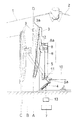
即ち本発明の緊張法は、図1、図4等に示されるように、シャツ1を装着させる人体型2の両側部に縦に設けられている側部押圧部材3を、この側部押圧部材3の張り出し用の駆動装置4で、人体型2の側方に自重で傾倒する位置まで張り出し、自重で傾倒する側部押圧部材3でシャツ1の側部を張る最初の緊張処理と、シャツ1の前後がプレスされると、駆動装置4を再び駆動させて側部押圧部材3を更に張り出し、シャツ1の側部を緊張仕上げする2番目の緊張処理とでシャツ1の側部を仕上げることを特徴とする(請求項1)。
The present invention employs the following technical means in order to solve the above problems.
That is, as shown in FIGS. 1 and 4 and the like, the tension method of the present invention uses side pressing members 3 provided vertically on both sides of the human body 2 on which the shirt 1 is worn. 3, the first tensioning process in which the side part of the shirt 1 is stretched by the side pressing member 3 which is projected to the side of the human body 2 by its own weight and is tilted by its own weight. When the front and rear are pressed, the side of the shirt 1 is finished by the second tensioning process in which the driving device 4 is driven again to further extend the side pressing member 3 and tension the side of the shirt 1. It is characterized (claim 1).

また本発明の緊張法に使用する装置は、図1〜図3等に示されるように、シャツ1を装着させる人体型2の両側部に縦に設けられている側部押圧部材3と、この側部押圧部材3の張り出し用の駆動装置4と、この駆動装置4を制御し、側部押圧部材3に、最初の緊張処理と2番目の緊張処理を行なわせるためのコントローラ7とを備えて形成されている(請求項2)。   Moreover, as shown in FIGS. 1 to 3 and the like, the apparatus used for the tension method of the present invention includes a side pressing member 3 provided vertically on both sides of the human body 2 on which the shirt 1 is worn, A driving device 4 for projecting the side pressing member 3 and a controller 7 for controlling the driving device 4 to cause the side pressing member 3 to perform the first tensioning process and the second tensioning process are provided. (Claim 2).

本発明の場合、駆動装置4は、例えばエアシリンダやモータで実現される。またコントローラ7としては、例えばマイクロコンピュータやシーケンサーがある。   In the case of the present invention, the driving device 4 is realized by, for example, an air cylinder or a motor. The controller 7 includes, for example, a microcomputer and a sequencer.

また本発明の場合、駆動装置4は、人体型2の下部の内側に配置されているのが好ましい(請求項3)。
なぜならこれによると、駆動装置4を人体型2の外に設ける場合に比べ、人体型2の側部の開口面積を狭めることができ、人体型2内に供給する熱風や蒸気が、人体型2の側部から漏れることを防止できるからである。
In the case of the present invention, it is preferable that the drive device 4 is disposed inside the lower part of the human body 2 (Claim 3).
Because, according to this, compared with the case where the driving device 4 is provided outside the human body 2, the opening area of the side of the human body 2 can be reduced, and the hot air and steam supplied into the human body 2 are It is because it can prevent leaking from the side part.

また本発明は、図1等に示されるように、側部押圧部材3を支持する起立状の支持部材5の下部が、この支持部材5の枢着用の軸11の位置から人体型2の内方に屈曲され、この屈曲箇所5aの下端に、駆動装置4としてのエアシリンダのロッドが枢着されているのが好ましい(請求項4)。
なぜならこれによると、支持部材5の下部が屈曲しているため、駆動装置4としてのエアシリンダを人体型2内に納め易くなるからである。
In addition, as shown in FIG. 1 and the like, the present invention is such that the lower part of the upright support member 5 that supports the side pressing member 3 is located inside the human body 2 from the position of the pivot shaft 11 of the support member 5. It is preferable that the rod of the air cylinder as the drive device 4 is pivotally attached to the lower end of the bent portion 5a.
This is because the lower part of the support member 5 is bent, so that the air cylinder as the driving device 4 can be easily accommodated in the human body mold 2.

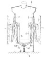
またこの場合、本発明は、図5に示されるように、人体型2の下部の左右方向の中央に、駆動装置4としてのエアシリンダがロッドを上にして起立状に一台設けられているのが好ましい(請求項5)。
なぜならこれによると、駆動装置4が一台のため、側部押圧部材3を同期させ易くなり、部品コストや製造コストを低減できるからである。またこの場合は、駆動装置4が一台であるから、人体型2の下部の空きスペースを増大でき、また人体型2内に供給する熱風や蒸気の流れを乱すことがないからである。
In this case, as shown in FIG. 5, in the present invention, one air cylinder as the driving device 4 is provided in a standing manner with the rod facing upward in the center of the lower part of the human body 2 in the left-right direction. (Claim 5).
This is because, according to this, since there is only one driving device 4, the side pressing member 3 can be easily synchronized, and the component cost and manufacturing cost can be reduced. Further, in this case, since there is only one drive device 4, the empty space below the human body mold 2 can be increased, and the flow of hot air and steam supplied into the human body mold 2 is not disturbed.

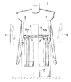
更に本発明は、図6に示されるように、駆動装置4がエアシリンダであり、このエアシリンダが、人体型2の胴部内に、ロッドを人体型2の側方に向けて横向き状に左右一対設けられているのでも良い(請求項6)。
この場合は、側部押圧部材3を、至近距離から制御でき、能力の小さい、安価なエアシリンダの使用が可能になるものである。またこれによると、駆動装置4が高い位置にあるため、人体型2内に供給する熱風や蒸気の流れを乱すことがなく、シャツ1を早く綺麗に仕上げることができるものである。
Furthermore, as shown in FIG. 6, in the present invention, the driving device 4 is an air cylinder, and this air cylinder is horizontally placed in the body part of the human body mold 2 so that the rod faces sideways of the human body mold 2. A pair may be provided (Claim 6).
In this case, the side pressing member 3 can be controlled from a close distance, and an inexpensive air cylinder having a small capacity can be used. Further, according to this, since the driving device 4 is at a high position, the flow of hot air or steam supplied into the human body 2 is not disturbed, and the shirt 1 can be finished quickly and beautifully.

本発明は、このように構成されているから、これによれば、シャツのサイズに合わせて側部押圧部材の張り出し距離を選定する必要がない。
それ故、本発明によれば、作業者の判断に左右されることなく、人体型に着せたシャツの側部を、簡単、確実、且つ綺麗に緊張仕上げできる。
Since this invention is comprised in this way, according to this, it is not necessary to select the protrusion distance of a side part press member according to the size of a shirt.
Therefore, according to the present invention, the side portion of the shirt worn on the human body can be tension-finished easily, surely and neatly without being influenced by the judgment of the operator.

以下、本発明を実施するための最良の形態を説明する。
図1等において、1はワイシャツ等のシャツである。また2は、このシャツ1を装着させる人体型であり、3はこの人体型2の両側部に縦に設けられている側部押圧部材である。また4は、側部押圧部材3を人体型2の側方に張り出させるための駆動装置である。
Hereinafter, the best mode for carrying out the present invention will be described.
In FIG. 1 etc., 1 is shirts, such as a shirt. Reference numeral 2 denotes a human body type on which the shirt 1 is to be worn. Reference numeral 3 denotes a side pressing member provided vertically on both sides of the human body mold 2. Reference numeral 4 denotes a driving device for projecting the side pressing member 3 to the side of the human body 2.

本発明の緊張法は、上記の駆動装置4で側部押圧部材3を、人体型2の側方に自重で傾倒する位置(図1のAの位置)まで張り出し、自重で傾倒する側部押圧部材3で、シャツ1の側部を張る最初の緊張処理(図1のBの位置)と、シャツ1の前後がプレスされると、駆動装置4を再び駆動させて側部押圧部材3を更に張り出し、シャツ1の側部を緊張仕上げする2番目の緊張処理(図1のCの位置)とでシャツ1の側部を仕上げるものである。   In the tension method of the present invention, the side pressing member 3 is projected to the position where the side pressing member 3 is tilted to the side of the human body 2 by its own weight (position A in FIG. 1) by the driving device 4 and is tilted by its own weight. When the first tensioning process (position B in FIG. 1) for stretching the side portion of the shirt 1 with the member 3 and the front and rear of the shirt 1 are pressed, the driving device 4 is driven again to further move the side pressing member 3. The side portion of the shirt 1 is finished by overhanging and the second tension processing (position C in FIG. 1) that finishes the side portion of the shirt 1 in tension.

上記の側部押圧部材3は、初期の位置(図1、図3の実線状態参照)から、駆動装置4により人体型2の側方に張り出される。そして側部押圧部材3は、垂直線(図1のD)を僅かに超えた位置から自重で傾倒する。駆動装置4は、側部押圧部材3が自重で傾倒する位置に至ると、駆動が停止する。この実施形態の場合、駆動装置4は、エアシリンダで構成されている。従ってエアシリンダのロッドの延伸動作が停止し、そしてロッドの引き出しが自由になる。その結果、側部押圧部材3は、自重で人体型2の側方に傾倒し、シャツ1の側部を押して停止する。これにより、シャツ1の側部が張られ、最初の緊張処理が行われる。   The side pressing member 3 is projected from the initial position (see the solid line state in FIGS. 1 and 3) to the side of the human body 2 by the driving device 4. And the side part press member 3 inclines with its own weight from the position which slightly exceeded the perpendicular line (D of FIG. 1). The driving device 4 stops driving when the side pressing member 3 reaches a position where the side pressing member 3 is tilted by its own weight. In the case of this embodiment, the drive device 4 is composed of an air cylinder. Accordingly, the extending operation of the rod of the air cylinder is stopped, and the rod can be pulled out freely. As a result, the side pressing member 3 tilts to the side of the human body 2 by its own weight, and presses the side of the shirt 1 to stop. Thereby, the side part of the shirt 1 is stretched and the first tension processing is performed.

この場合、側部押圧部材3は、シャツ1のサイズに合わせて側部を緊張する。即ち、シャツ1のサイズが大きい場合は、側部押圧部材3を支持する起立状の支持部材5の傾斜角度が大きい状態で、またシャツ1のサイズが小さいときは傾斜角度が小さい状態で緊張する。なおこの場合、シャツ1は、人体型2の表面に吸着されているため、前側等が乱れることはない。またシャツ1は、吸着に代え、ボタンを利用して前側の乱れが防止されるのでも良い。   In this case, the side pressing member 3 tensions the side according to the size of the shirt 1. That is, when the size of the shirt 1 is large, the upright support member 5 that supports the side pressing member 3 is strained with a large inclination angle, and when the shirt 1 is small, the tension is small. . In this case, since the shirt 1 is adsorbed on the surface of the human body 2, the front side and the like are not disturbed. Further, the shirt 1 may be prevented from being disturbed on the front side by using a button instead of suction.

そして本発明は、プレス鏝6(図2参照)がシャツ1の前後をプレスすると、駆動装置4が再び駆動し、側部押圧部材3が人体型2の側方に更に張り出る。これによりシャツ1は、プレス鏝6で前後が押さえられた状態で、2番目の緊張処理が行われる。なお図2に示されるシャツプレス仕上げ機の場合は、前側のプレス鏝6が、左右方向にスライド自在に形成されている。   In the present invention, when the press rod 6 (see FIG. 2) presses the front and back of the shirt 1, the driving device 4 is driven again, and the side pressing member 3 further protrudes to the side of the human body 2. As a result, the second tension process is performed on the shirt 1 in a state where the front and rear are pressed by the press rod 6. In the case of the shirt press finishing machine shown in FIG. 2, the front press bar 6 is formed to be slidable in the left-right direction.

次に、プレス鏝6によるプレスが終了し、プレス鏝6が人体型2の前後から離れると、駆動装置4が逆に駆動する。この結果、側部押圧部材3が復帰し、シャツ1の前後がプレス仕上げされると共に、側部が緊張仕上げされる。   Next, when the press rod 6 is pressed and the press rod 6 is separated from the front and back of the human body 2, the driving device 4 is driven in reverse. As a result, the side pressing member 3 is restored, the front and back of the shirt 1 are press-finished, and the side is tension-finished.

次にこのような本発明の緊張法に使用する胴張り装置について、説明する。
本発明の装置は、図1〜図3に示されるように、シャツ1を装着させる人体型2の両側部に縦に設けられている側部押圧部材3と、この側部押圧部材3の張り出し用の駆動装置4と、この駆動装置4を制御し、側部押圧部材3に最初の緊張処理と2番目の緊張処理を行なわせるためのコントローラ7とを備えて形成されている。
Next, a description will be given of the waist tension device used in the tension method of the present invention.
As shown in FIGS. 1 to 3, the apparatus of the present invention includes a side pressing member 3 provided vertically on both sides of a human body 2 on which a shirt 1 is to be worn, and an overhang of the side pressing member 3. And a controller 7 for controlling the driving device 4 and causing the side pressing member 3 to perform the first tensioning process and the second tensioning process.

上記の側部押圧部材3は、人体型2の側方に凹み面を向けて弓形状に形成されている。そしてこの側部押圧部材3は、シャツ1の側部内面にあてがわれる可撓性の線状部材3aが上下端に弦状に張られている。この線状部材3aは、この実施形態では細いコイルスプリングで構成されている。   The side pressing member 3 is formed in a bow shape with the concave surface facing the side of the human body 2. The side pressing member 3 has a flexible linear member 3a applied to the inner surface of the side portion of the shirt 1 stretched in a string shape at the upper and lower ends. In this embodiment, the linear member 3a is constituted by a thin coil spring.

側部押圧部材3を支持する支持部材5の上端は、連結プレート8を介して側部押圧部材3の略中央位置に枢着されている。9は、人体型2の前後方向に沿って水平状に配置されている枢着ピンである。側部押圧部材3は、この枢着ピン9を中心に人体型2の左右方向に所定角度回動する。また支持部材5の下部は、人体型2内の取付部10に、軸11を介して枢着されている。   The upper end of the support member 5 that supports the side pressing member 3 is pivotally attached to a substantially central position of the side pressing member 3 via a connecting plate 8. 9 is a pivot pin arranged horizontally along the front-rear direction of the human body 2. The side pressing member 3 rotates by a predetermined angle in the left-right direction of the human body 2 around the pivot pin 9. Further, the lower portion of the support member 5 is pivotally attached to the attachment portion 10 in the human body 2 via the shaft 11.

またこの実施形態の本発明は、連結プレート8の内側の上部に起立片8aが立ち上げられている。そしてこの起立片8aの上端と、側部押圧部材3の対応する背側の外縁位置とが、引張りバネ12で連結されている。この引張りバネ12は、シャツ1の側部の湾曲ラインによって側部押圧部材3が枢着ピン9を中心に傾いたとき、側部押圧部材3の復帰を容易化するためのものである。なお側部押圧部材3は、通常、人体型2と共に、カバー(図示せず)で覆われている。   Further, according to the present invention of this embodiment, an upright piece 8 a is raised at the upper part inside the connecting plate 8. The upper end of the upright piece 8 a and the corresponding outer edge position on the back side of the side pressing member 3 are connected by a tension spring 12. This tension spring 12 is for facilitating the return of the side pressing member 3 when the side pressing member 3 is tilted around the pivot pin 9 by the curved line on the side of the shirt 1. The side pressing member 3 is usually covered with a cover (not shown) together with the human body shape 2.

上記の駆動装置4は、この実施形態ではエアシリンダが使用され、人体型2の下部の内側に、ロッドを内方に向けて傾斜状に配置されている。側部押圧部材3を支持する起立状の支持部材5の下部は、軸11から人体型2の内方に屈曲されている。駆動装置4としてのエアシリンダのロッドは、この屈曲箇所5aの下端に枢着されている。   In this embodiment, the driving device 4 uses an air cylinder, and is disposed inside the lower part of the human body 2 so as to be inclined with the rod facing inward. A lower portion of the upright support member 5 that supports the side pressing member 3 is bent inward of the human body 2 from the shaft 11. The rod of the air cylinder as the drive device 4 is pivotally attached to the lower end of the bent portion 5a.

上記のコントローラ7は、例えばマイクロコンピュータで構成されている。このコントローラ7は、上記の最初の緊張処理、及び2番目の緊張処理を行わせるプログラムが組み込まれている。そしてこのコントローラ7は、駆動装置4としてのエアシリンダのエアの流路を制御する電磁弁13と電気的に接続されている。   The controller 7 is composed of, for example, a microcomputer. The controller 7 incorporates a program for performing the first tension process and the second tension process. The controller 7 is electrically connected to an electromagnetic valve 13 that controls the air flow path of an air cylinder as the driving device 4.

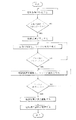
次にこの実施形態に係る本発明の作用を、図4等に従って説明する。
先ず作業者は、シャツ1が人体型2に装着されている状態で、始動スイッチ14(図2参照)を入れる。すると、コントローラ7からの信号を受けて電磁弁13がエアの流路を開き、駆動装置4としてのエアシリンダが、支持部材5の屈曲箇所5aの下端を、人体型2の内方に押し込む。その結果、支持部材5が、軸11を中心に人体型2の側方に回動する。
Next, the operation of the present invention according to this embodiment will be described with reference to FIG.
First, the operator turns on the start switch 14 (see FIG. 2) while the shirt 1 is attached to the human body 2. Then, in response to the signal from the controller 7, the electromagnetic valve 13 opens the air flow path, and the air cylinder as the driving device 4 pushes the lower end of the bent portion 5 a of the support member 5 inward of the human body 2. As a result, the support member 5 rotates to the side of the human body 2 around the shaft 11.

そして設定時間が経過すると、駆動装置4としてのエアシリンダの駆動が停止し、ロッドの動きが自由になる。設定時間は、側部押圧部材3を自重で傾倒する位置に配置させることができる時間である。   And when set time passes, the drive of the air cylinder as the drive device 4 stops, and movement of a rod becomes free. The set time is a time during which the side pressing member 3 can be arranged at a position where the side pressing member 3 is tilted by its own weight.

従って本発明の場合、設定時間が経過すると、図1に示されるように、側部押圧部材3が自重で傾倒する位置(同図A参照)に配置される。そしてこの位置に側部押圧部材3が配置されると、側部押圧部材3は自重で人体型2の側方に傾倒し、シャツ1の側部を緊張する(同図B参照)。具体的には側部押圧部材3に張られている線状部材3aが、シャツ1の側部内面に押し付けられ、線状部材3aがシャツ1の内側の湾曲ラインに沿って撓みながら、シャツ1の側部を人体型2の側方に緊張する。   Therefore, in the case of the present invention, when the set time elapses, as shown in FIG. 1, the side pressing member 3 is disposed at a position where the side pressing member 3 tilts by its own weight (see FIG. 1A). And if the side part press member 3 is arrange | positioned in this position, the side part press member 3 will incline to the side of the human body shape 2 with dead weight, and will tension the side part of the shirt 1 (refer the same figure B). Specifically, the linear member 3 a stretched on the side pressing member 3 is pressed against the inner surface of the side of the shirt 1, and the linear member 3 a bends along the curved line inside the shirt 1 while the shirt 1 Tighten the side of the human body 2 to the side.

そして前後一対のプレス鏝6(図2参照)がシャツ1の前後をプレスすると、コントローラ7からの信号を受けて電磁弁13が再び作動し、駆動装置4としてのエアシリンダのロッドが少し伸びる。これによりシャツ1の側部が更に張られ、2番目の緊張処理が行われる(図1のC参照)。なおこの実施形態の場合、前側のプレス鏝6は、人体型2の右側の退避位置から、人体型2の前側に移動してシャツ1をプレスするよう構成されている。   When a pair of front and rear press rods 6 (see FIG. 2) press the front and back of the shirt 1, the electromagnetic valve 13 is actuated again in response to a signal from the controller 7, and the rod of the air cylinder as the drive device 4 is slightly extended. Thereby, the side part of the shirt 1 is further tensioned and the second tension process is performed (see C in FIG. 1). In the case of this embodiment, the front press bar 6 is configured to move from the retracted position on the right side of the human body 2 to the front side of the human body 2 to press the shirt 1.

次にプレス鏝6によるプレスが終了すると、コントローラ7からの信号を受けて電磁弁13がエアの流路を切り替え、駆動装置4としてのエアシリンダのロッドが収縮する。この結果、支持部材5が、軸11を中心に人体型2の側に回動し、側部押圧部材3が復帰する。   Next, when the press by the press rod 6 is completed, the solenoid valve 13 switches the air flow path in response to a signal from the controller 7, and the rod of the air cylinder as the driving device 4 contracts. As a result, the support member 5 rotates around the shaft 11 toward the human body 2 and the side pressing member 3 returns.

以上の処において、上例では駆動装置4としてのエアシリンダが、人体型2の両側の側部押圧部材3に個別に設けられているが、本発明はこれに限定されるものではない。
即ち本発明は、図5に示されるように、人体型2の下部の左右方向の中央に、駆動装置4としてのエアシリンダが、ロッドを上にして起立状に一台設けられ、この一台の駆動装置4で左右の側部押圧部材3を、同時に動作させるよう構成されているのでも良い。
なぜならこれによると、エアシリンダが一台で済み、部品コスト、製造コストを低減できるからである。この場合、支持部材5の屈曲箇所5aには長孔5bが形成され、エアシリンダのロッドは、この長孔5bを介して屈曲箇所5aに枢着されている。
In the above, in the above example, the air cylinder as the driving device 4 is individually provided on the side pressing members 3 on both sides of the human body 2, but the present invention is not limited to this.
That is, as shown in FIG. 5, in the present invention, an air cylinder as a driving device 4 is provided in an upright manner with a rod facing upward at the center in the left-right direction of the lower part of the human body 2. The left and right side pressing members 3 may be simultaneously operated by the driving device 4.
This is because only one air cylinder is required, and the parts cost and manufacturing cost can be reduced. In this case, a long hole 5b is formed in the bent portion 5a of the support member 5, and the rod of the air cylinder is pivotally attached to the bent portion 5a via the long hole 5b.

また本発明は、図6に示されるように、駆動装置4としてのエアシリンダが、人体型2の胴部内に、ロッドを人体型2の側方に向けて横向き状に左右一対設けられているのでも良い。15は、駆動装置4を取り付けるための支柱である。駆動装置4としてのエアシリンダのロッドは、連結プレート8の起立片8aに枢着されている。
この場合は、側部押圧部材3の近くでエアシリンダを作動させ、側部押圧部材3を動作させることができるため、能力の小さい、安価なエアシリンダの使用が可能になる。またこの場合は、駆動装置4の配置位置が高いため、人体型2の下部に駆動装置4を配置する場合に比べ、人体型2内に下側から供給する熱風や蒸気の流れを乱すことがない。従ってこれによると、シャツ1を満遍なく、早く乾燥でき、仕上がり状態を良くできる。
In the present invention, as shown in FIG. 6, a pair of air cylinders as the driving device 4 are provided in the body part of the human body 2 in the lateral direction with the rod facing the side of the human body 2. It's okay. Reference numeral 15 denotes a support for attaching the driving device 4. The rod of the air cylinder as the driving device 4 is pivotally attached to the upright piece 8 a of the connecting plate 8.
In this case, since the air cylinder can be operated near the side pressing member 3 and the side pressing member 3 can be operated, it is possible to use an inexpensive air cylinder having a small capacity. Further, in this case, since the arrangement position of the driving device 4 is high, the flow of hot air or steam supplied from below into the human body shape 2 may be disturbed compared to the case where the driving device 4 is disposed below the human body shape 2. Absent. Therefore, according to this, the shirt 1 can be uniformly and quickly dried, and the finished state can be improved.

本発明の好適な一実施形態を示す一部を切欠した要部正面図である。It is the principal part front view which notched a part which shows suitable one Embodiment of this invention. 本発明の装置を備えたシャツプレス仕上げ機の正面図である。It is a front view of the shirt press finishing machine provided with the apparatus of this invention. 本発明の装置の要部正面図である。It is a principal part front view of the apparatus of this invention. 本発明の作用を説明するためのフローチャートである。It is a flowchart for demonstrating the effect | action of this invention. 本発明の装置の他の実施形態を示す要部縦断面図である。It is a principal part longitudinal cross-sectional view which shows other embodiment of the apparatus of this invention. 本発明の装置の更に他の実施形態を示す要部縦断面図である。It is a principal part longitudinal cross-sectional view which shows other embodiment of the apparatus of this invention.

符号の説明Explanation of symbols

1 シャツ
2 人体型
3 側部押圧部材
4 駆動装置
7 コントローラ
DESCRIPTION OF SYMBOLS 1 Shirt 2 Human body type 3 Side part pressing member 4 Drive device 7 Controller

Claims (6)

シャツを装着させる人体型の両側部に縦に設けられている側部押圧部材を、この側部押圧部材の張り出し用の駆動装置で、人体型の側方に自重で傾倒する位置まで張り出し、自重で傾倒する側部押圧部材でシャツの側部を張る最初の緊張処理と、シャツの前後がプレスされると、駆動装置を再び駆動させて側部押圧部材を更に張り出し、シャツの側部を緊張仕上げする2番目の緊張処理とでシャツの側部を仕上げることを特徴とするシャツの側部の緊張法。   The side pressing members, which are provided vertically on both sides of the human body on which the shirt is to be worn, are projected to the position where the side body is tilted by its own weight with the driving device for projecting the side pressing member. When the front and back of the shirt are pressed with the side pressing member that tilts at the side, and the front and back of the shirt are pressed, the drive unit is driven again to further extend the side pressing member and tension the side of the shirt. A side tensioning method for a shirt characterized in that the side of the shirt is finished with a second tensioning process to be finished. 請求項1記載のシャツの側部の緊張法に使用する胴張り装置であって、シャツを装着させる人体型の両側部に縦に設けられている側部押圧部材と、この側部押圧部材の張り出し用の駆動装置と、この駆動装置を制御し、側部押圧部材に、最初の緊張処理と2番目の緊張処理を行なわせるためのコントローラとを備えて形成されていることを特徴とする胴張り装置。   A waistline device for use in a method of tensioning a side portion of a shirt according to claim 1, wherein a side pressing member provided vertically on both sides of a human body on which the shirt is to be worn, and the side pressing member A cylinder characterized by comprising a drive device for overhanging and a controller for controlling the drive device and causing the side pressing member to perform the first tension process and the second tension process. Tensioning device. 請求項2記載の胴張り装置であって、駆動装置が、人体型の下部の内側に配置されていることを特徴とする胴張り装置。   3. The waist tension device according to claim 2, wherein the driving device is disposed inside the lower part of the human body shape. 請求項3記載の胴張り装置であって、側部押圧部材を支持する起立状の支持部材の下部が、この支持部材の枢着用の軸の位置から人体型の内方に屈曲され、この屈曲箇所の下端に、駆動装置としてのエアシリンダのロッドが枢着されていることを特徴とする胴張り装置。   4. The waistline device according to claim 3, wherein a lower portion of the upright support member that supports the side pressing member is bent inward of the human body shape from the position of the pivot shaft of the support member. A waisting device, wherein a rod of an air cylinder as a driving device is pivotally attached to a lower end of the part. 請求項4記載の胴張り装置であって、人体型の下部の左右方向の中央に、駆動装置としてのエアシリンダが、ロッドを上にして起立状に一台設けられていることを特徴とする胴張り装置。   5. The waist-stretching device according to claim 4, wherein an air cylinder as a driving device is provided in a standing manner with a rod facing upward in the center of the lower part of the human body in the left-right direction. Torsion equipment. 請求項2記載の胴張り装置であって、駆動装置がエアシリンダであり、このエアシリンダが、人体型の胴部内に、ロッドを人体型の側方に向けて横向き状に左右一対設けられていることを特徴とする胴張り装置。   3. The torsional device according to claim 2, wherein the drive device is an air cylinder, and the air cylinder is provided in the human body torso in a pair of left and right in a lateral direction with the rod facing the side of the human body. A torso device characterized in that
JP2007193017A 2007-07-25 2007-07-25 Shirt side waistline device Active JP5026878B2 (en)

Priority Applications (1)

Application Number Priority Date Filing Date Title
JP2007193017A JP5026878B2 (en) 2007-07-25 2007-07-25 Shirt side waistline device

Applications Claiming Priority (1)

Application Number Priority Date Filing Date Title
JP2007193017A JP5026878B2 (en) 2007-07-25 2007-07-25 Shirt side waistline device

Publications (2)

Publication Number Publication Date
JP2009028126A true JP2009028126A (en) 2009-02-12
JP5026878B2 JP5026878B2 (en) 2012-09-19

Family

ID=40399350

Family Applications (1)

Application Number Title Priority Date Filing Date
JP2007193017A Active JP5026878B2 (en) 2007-07-25 2007-07-25 Shirt side waistline device

Country Status (1)

Country Link
JP (1) JP5026878B2 (en)

Cited By (2)

* Cited by examiner, † Cited by third party
Publication number Priority date Publication date Assignee Title
KR101234809B1 (en) * 2011-02-16 2013-02-19 최윤섭 Apparatus for tension of waist of shirts press
JP2015012985A (en) * 2013-07-05 2015-01-22 株式会社三幸社 Shirt finish machine

Citations (2)

* Cited by examiner, † Cited by third party
Publication number Priority date Publication date Assignee Title
JPS63260600A (en) * 1987-04-17 1988-10-27 富士車輌株式会社 Pressing method of undershirt drum section
JP2004305311A (en) * 2003-04-03 2004-11-04 Sankosha:Kk Torso tensioning mechanism of shirt press-finishing machine

Patent Citations (2)

* Cited by examiner, † Cited by third party
Publication number Priority date Publication date Assignee Title
JPS63260600A (en) * 1987-04-17 1988-10-27 富士車輌株式会社 Pressing method of undershirt drum section
JP2004305311A (en) * 2003-04-03 2004-11-04 Sankosha:Kk Torso tensioning mechanism of shirt press-finishing machine

Cited By (2)

* Cited by examiner, † Cited by third party
Publication number Priority date Publication date Assignee Title
KR101234809B1 (en) * 2011-02-16 2013-02-19 최윤섭 Apparatus for tension of waist of shirts press
JP2015012985A (en) * 2013-07-05 2015-01-22 株式会社三幸社 Shirt finish machine

Also Published As

Publication number Publication date
JP5026878B2 (en) 2012-09-19

Similar Documents

Publication Publication Date Title
JP5026878B2 (en) Shirt side waistline device
US7594597B2 (en) Method for tensioning side portions of shirt and body tensioning device applied for the method
JP2009285074A5 (en)
KR100908511B1 (en) Tension Method of Shirt Side and Torso Tension Device Used in This Method
US7438205B2 (en) Shirt finishing machine
JP2002191900A (en) Method and device for shaping and finishing texture
CN101380189B (en) Tension method of side of shirt and body tensioner applied in the tension method
EP2031122B1 (en) Method for tensioning side portions of shirt and body tensioning device applied for the method
US6868996B1 (en) Body tension apparatus for shirts press machine
JP6960710B2 (en) sewing machine
JP4409522B2 (en) Shirt finishing machine
KR101609728B1 (en) Shirts press and its control method
US7392919B2 (en) Shirt finishing machine
JP4227827B2 (en) Shirt press finishing machine trunking mechanism
KR20120109811A (en) The trouser press machine of device presses
US20070119245A1 (en) Seam abrasion testing device and method of use
EP1978148B1 (en) Shirt finishing machine
JPH11128579A (en) Presser foot for pocket setter
JP2006000430A (en) Shirt finish machine
JP2002210298A (en) Trousers finishing machine
JPH0642637Y2 (en) Split press table
JP4281955B2 (en) Shirt finisher with color stretch function
KR100490104B1 (en) Body tension apparatus for shirts press machine
JPH02193699A (en) Shirt finisher
JP3181225U (en) Body expansion mechanism of clothing press machine

Legal Events

Date Code Title Description
A621 Written request for application examination

Free format text: JAPANESE INTERMEDIATE CODE: A621

Effective date: 20100423

A977 Report on retrieval

Free format text: JAPANESE INTERMEDIATE CODE: A971007

Effective date: 20111226

A131 Notification of reasons for refusal

Free format text: JAPANESE INTERMEDIATE CODE: A131

Effective date: 20120117

A521 Request for written amendment filed

Free format text: JAPANESE INTERMEDIATE CODE: A523

Effective date: 20120315

TRDD Decision of grant or rejection written
A01 Written decision to grant a patent or to grant a registration (utility model)

Free format text: JAPANESE INTERMEDIATE CODE: A01

Effective date: 20120515

A01 Written decision to grant a patent or to grant a registration (utility model)

Free format text: JAPANESE INTERMEDIATE CODE: A01

A61 First payment of annual fees (during grant procedure)

Free format text: JAPANESE INTERMEDIATE CODE: A61

Effective date: 20120621

FPAY Renewal fee payment (event date is renewal date of database)

Free format text: PAYMENT UNTIL: 20150629

Year of fee payment: 3

R150 Certificate of patent or registration of utility model

Ref document number: 5026878

Country of ref document: JP

Free format text: JAPANESE INTERMEDIATE CODE: R150

Free format text: JAPANESE INTERMEDIATE CODE: R150

R250 Receipt of annual fees

Free format text: JAPANESE INTERMEDIATE CODE: R250

R250 Receipt of annual fees

Free format text: JAPANESE INTERMEDIATE CODE: R250

R250 Receipt of annual fees

Free format text: JAPANESE INTERMEDIATE CODE: R250

R250 Receipt of annual fees

Free format text: JAPANESE INTERMEDIATE CODE: R250

R250 Receipt of annual fees

Free format text: JAPANESE INTERMEDIATE CODE: R250

R250 Receipt of annual fees

Free format text: JAPANESE INTERMEDIATE CODE: R250

R250 Receipt of annual fees

Free format text: JAPANESE INTERMEDIATE CODE: R250

R250 Receipt of annual fees

Free format text: JAPANESE INTERMEDIATE CODE: R250

R250 Receipt of annual fees

Free format text: JAPANESE INTERMEDIATE CODE: R250

R250 Receipt of annual fees

Free format text: JAPANESE INTERMEDIATE CODE: R250