JP2009028062A - Blood sampling device for biosensor and sensor chip measuring apparatus - Google Patents
Blood sampling device for biosensor and sensor chip measuring apparatus Download PDFInfo
- Publication number
- JP2009028062A JP2009028062A JP2007191904A JP2007191904A JP2009028062A JP 2009028062 A JP2009028062 A JP 2009028062A JP 2007191904 A JP2007191904 A JP 2007191904A JP 2007191904 A JP2007191904 A JP 2007191904A JP 2009028062 A JP2009028062 A JP 2009028062A
- Authority
- JP
- Japan
- Prior art keywords
- biosensor
- sensor chip
- blood
- introduction hole
- puncture needle
- Prior art date
- Legal status (The legal status is an assumption and is not a legal conclusion. Google has not performed a legal analysis and makes no representation as to the accuracy of the status listed.)
- Pending
Links
Images


Landscapes
- Measurement Of The Respiration, Hearing Ability, Form, And Blood Characteristics Of Living Organisms (AREA)
Abstract
Description
本発明は、血糖値センサ等のセンサチップ測定装置に使用されるバイオセンサ用採血器に関する。より具体的には、指等の被検査体を穿刺し、穿刺により流出した血液試料を、センサチップ内に導入するバイオセンサ用採血器に関する。 The present invention relates to a blood collecting device for a biosensor used in a sensor chip measuring device such as a blood glucose level sensor. More specifically, the present invention relates to a biosensor blood collection device that punctures an object to be examined such as a finger and introduces a blood sample that has flowed out by puncture into a sensor chip.
バイオセンサチップは、血液等の微量試料をチップ内に導入し、該チップ内で該微量試料についての生化学反応を起こし、この生化学反応により得られる情報をチップ外へ出力するセンサチップである。このバイオセンサチップを使用するセンサチップ測定装置(バイオセンサ)は、例えば、血液中のグルコース量(血糖値)を測定する血糖値センサとして、糖尿病を自己管理し予防する家庭内健康診断(セルフケア)等に使用されている。 The biosensor chip is a sensor chip that introduces a trace sample such as blood into the chip, causes a biochemical reaction on the trace sample in the chip, and outputs information obtained by the biochemical reaction to the outside of the chip. . A sensor chip measuring apparatus (biosensor) using this biosensor chip is a home health diagnosis (self-care) that self-manages and prevents diabetes, for example, as a blood glucose level sensor that measures the amount of glucose in blood (blood glucose level). Etc. are used.
血糖値センサ等、試料が血液であるセンサチップ測定装置は、穿刺針により被検査体を穿刺して血液を流出させる穿刺部、流出した血液をチップ内に導入するための採血器、及びチップ内での反応から得られた信号を処理するデータ処理部等を有する。従来のバイオセンサ測定装置では、穿刺部及び採血器が別個の装置である場合が多く、穿刺により流出した微量な血液を、採血器に点着する動作が必要であった。 A sensor chip measuring device whose blood sample is blood, such as a blood glucose level sensor, is a puncture section for puncturing a test object with a puncture needle to flow out blood, a blood collection device for introducing the flowed blood into the chip, and the chip A data processing unit for processing a signal obtained from the reaction in (1). In the conventional biosensor measurement device, the puncture unit and the blood collection device are often separate devices, and an operation for spotting a small amount of blood that has flowed out due to the puncture to the blood collection device is required.
一方、穿刺部及び採血器等が一体化されたセンサも、国際公開WO2002−056769号公報(特許文献1)等に開示されている。特許文献1に記載のセンサは、被検体の皮膚を突き刺す(穿刺する)ことによりその体液(血液等)を採取するためのランセット(穿刺部及び採血器)を有し(請求項1)、穿刺部及び採血器等が一体化されたセンサである。
しかし、このセンサにおいても、穿刺後、引き続いて血液を点着する動作が必要であり(第21頁第10〜12行)、その操作性に問題があった。即ち、穿刺により流出した血液は微量であり、それを採血器等の試料導入部に点着する動作は困難であり、特に糖尿病患者に多い視力低下者にとっては困難である。その結果、センサチップへの試料の導入が不十分になり測定成功率が低下する問題も生じる。
However, this sensor also requires an operation of subsequently spotting blood after puncturing (
本発明は、微量な血液試料の採血器等への点着動作を要せずに、穿刺及び試料のチップへの導入を行うことができ、かつ高い測定成功率が得られるバイオセンサ用採血器、及びそれを用いたセンサチップ測定装置を提供することを課題とする。 The present invention is a biosensor blood collector that can perform puncturing and introduction of a sample into a chip without requiring a spotting operation of a small amount of blood sample to a blood collector or the like, and can obtain a high measurement success rate. Another object is to provide a sensor chip measuring apparatus using the same.
本発明者は、鋭意検討の結果、
センサチップの一端に穿刺針と試料導入孔を設け、該試料導入孔内に穿刺針を収納し、かつ試料導入孔を弾性体により形成する針一体型センサチップを使用すれば、穿刺により流出した血液試料を、点着動作を要せずに該試料導入孔に導入できること、さらに、
該針一体型センサチップの引き上げ(穿刺後、穿刺針の引き抜きのための、穿刺に際の移動の方向とは逆方向の移動)距離を規制することにより、血液試料の試料導入孔への導入が円滑になり高い測定成功率が得られること
を見出し、本発明を完成した。
As a result of earnest examination, the present inventor
If a needle-integrated sensor chip having a puncture needle and a sample introduction hole at one end of the sensor chip, storing the puncture needle in the sample introduction hole and forming the sample introduction hole with an elastic body, the sensor chip flows out by puncture A blood sample can be introduced into the sample introduction hole without requiring a spotting operation;
The blood sample is introduced into the sample introduction hole by regulating the distance of the needle-integrated sensor chip (the movement in the direction opposite to the movement direction at the time of puncture for the puncture needle to be pulled out after puncture). As a result, the present inventors have found that a high measurement success rate can be obtained and the present invention has been completed.
請求項1に記載の発明は、
試料導入孔を有する弾性体、及び前記試料導入孔内に収納される穿刺針が、その一端に設けられている針一体型センサチップを使用するバイオセンサ用採血器であって、
被検査体当接口、
前記穿刺針により、被検査体を穿刺するための穿刺手段、
穿刺後、前記針一体型センサチップを引き上げるための引き上げ手段、及び
引き上げの距離を規制し、かつ引き上げ距離の調節が可能な引き上げ規制手段、
を有することを特徴とするバイオセンサ用採血器、である。
The invention described in
An elastic body having a sample introduction hole, and a puncture needle housed in the sample introduction hole is a blood collection device for a biosensor using a needle integrated sensor chip provided at one end thereof,
Inspection object contact port,
Puncturing means for puncturing the object to be examined by the puncture needle,
A lifting means for lifting the needle-integrated sensor chip after puncturing, and a lifting regulating means for regulating the lifting distance and adjusting the lifting distance;
A biosensor blood collector, comprising:
本発明のバイオセンサ用採血器を構成するセンサチップは、バイオセンサチップ本体をその中に含み、かつその先端部(穿刺する方向にある端)に、被検査体を穿刺する穿刺針、及び試料導入孔を有する弾性体を設ける。さらに、外力により変形しやすいバイオセンサチップ本体の形状保持のため、ケーシング等の部材を用い、ケーシング内又はケーシング上等にバイオセンサチップ本体を収納してもよい。さらに、穿刺針の固定を確実にするための穿刺針固定具を用い、この穿刺針固定具をケーシング内に収納して固定してもよい。このようにバイオセンサチップは、バイオセンサチップ本体、穿刺針及び弾性体を必須の構成要素とするが、さらに、ケーシング、穿刺針固定具等を含んでもよい。 A sensor chip constituting the blood collecting device for a biosensor of the present invention includes a biosensor chip main body therein, and a puncture needle for puncturing an object to be inspected at a tip end thereof (an end in a puncturing direction), and a sample An elastic body having an introduction hole is provided. Furthermore, in order to maintain the shape of the biosensor chip body that is easily deformed by an external force, a member such as a casing may be used, and the biosensor chip body may be accommodated in the casing or on the casing. Further, a puncture needle fixture for ensuring the fixation of the puncture needle may be used, and the puncture needle fixture may be housed and fixed in a casing. As described above, the biosensor chip includes the biosensor chip body, the puncture needle, and the elastic body as essential components, but may further include a casing, a puncture needle fixture, and the like.
センサチップ内で穿刺針は、バイオセンサチップ本体に直接設けられていてもよいし、ケーシングに設けられていてもよい。又、前記のように、穿刺針固定具等の部材に設けられてケーシング内に固定されてもよい。試料導入孔を有する弾性体は、例えば、ケーシングに設けられていてもよい。 In the sensor chip, the puncture needle may be provided directly on the biosensor chip body, or may be provided on the casing. Further, as described above, it may be provided on a member such as a puncture needle fixture and fixed in the casing. The elastic body having the sample introduction hole may be provided in the casing, for example.
バイオセンサチップ本体は、少なくとも対極、作用極の一対からなる電極と、中空の反応部を有し、この反応部に血液試料が導入され測定のための反応が行われる。前記電極の一部(通常一端又はその近傍)はこの反応部内に露出する。通常、一方の電極上に反応を引き起こすための薬剤、例えば酵素が塗布されている。 The biosensor chip body has at least an electrode composed of a pair of a counter electrode and a working electrode, and a hollow reaction part. A blood sample is introduced into the reaction part, and a reaction for measurement is performed. A part of the electrode (usually one end or the vicinity thereof) is exposed in the reaction part. Usually, an agent for causing a reaction, such as an enzyme, is applied on one electrode.
反応部は、バイオセンサチップ本体外に開口している開口部を少なくとも1つ有するが、開口部の1つは、試料導入孔と連結しており、試料導入孔内に導入された試料は、反応部内に導入される。このようにして反応部内に導入された試料は反応を起こし、この反応により生じた電流は前記の電極により検知され、電気信号としてチップ外に出力される。 The reaction unit has at least one opening that is open to the outside of the biosensor chip body. One of the openings is connected to the sample introduction hole, and the sample introduced into the sample introduction hole is: Introduced into the reaction section. The sample introduced into the reaction part in this way undergoes a reaction, and the current generated by this reaction is detected by the electrode and output as an electrical signal outside the chip.
電極の他端は、バイオセンサチップ本体の他端側で露出している。この露出部を、データ処理部に電気的に接続している端子と導通させることにより、検知された信号は、データ処理部に出力され処理される。電極は、必要により、反応部に外部より電圧を印加する機能も有する。 The other end of the electrode is exposed on the other end side of the biosensor chip body. By making the exposed portion electrically connected to a terminal electrically connected to the data processing unit, the detected signal is output to the data processing unit and processed. The electrode also has a function of applying a voltage from the outside to the reaction part, if necessary.
採血器内でセンサチップは、例えばコネクターに接続され保持される。コネクターは、センサチップを保持するとともに、データ処理部と電気的に接続する端子を有するものであり、このコネクターを通してセンサチップからの信号がデータ処理部に出力される。 In the blood collection device, the sensor chip is connected to and held by a connector, for example. The connector holds the sensor chip and has a terminal that is electrically connected to the data processing unit, and a signal from the sensor chip is output to the data processing unit through this connector.
バイオセンサチップの先端部に設けられる弾性体とは、応力により縮み、応力の解除により復元する性質を有するものを言い、例えば、弾性材料(弾性変形する材質)からなる(中実の)成形体が挙げられるが、これのみに限定されない。中空部を有し中空部内の気体により弾性力が生じるもの等も、ここで言う弾性体に含まれる。なお、弾性材料としては、ゴム等の各種エラストマー等の他、スチレン系樹脂、フッ素樹脂等からなるものを挙げることができる。 The elastic body provided at the tip of the biosensor chip means a material that has a property of contracting due to stress and restoring by releasing stress, for example, a (solid) molded body made of an elastic material (elastically deformable material). However, it is not limited to this. What has a hollow part and produces elastic force with the gas in a hollow part etc. are also contained in the elastic body said here. Examples of the elastic material include various elastomers such as rubber and the like, as well as those made of styrene resin, fluororesin, and the like.
バイオセンサチップの先端部の弾性体は、穿刺により流出した試料を反応部に導入するための試料導入孔を有する。従って、この試料導入孔は、弾性体の先端側(被検査体側)及び反応部側のいずれにも開口する貫通孔である。 The elastic body at the tip of the biosensor chip has a sample introduction hole for introducing the sample that has flowed out by puncturing into the reaction section. Therefore, the sample introduction hole is a through hole that opens on both the distal end side (inspected object side) and the reaction part side of the elastic body.
被検査者の負担を軽減するためには採血量の減少が望まれ、そのためには、試料の必要量の減少が望まれる。試料の必要量を減少させるためには、試料導入孔の体積、即ち試料導入孔の径は小さいことが望ましい。又、毛管現象による導入をスムーズにするためにも、試料導入孔の径は小さいことが望ましい。 In order to reduce the burden on the examinee, it is desirable to reduce the amount of blood collected, and to that end, it is desirable to reduce the required amount of the sample. In order to reduce the required amount of sample, it is desirable that the volume of the sample introduction hole, that is, the diameter of the sample introduction hole is small. In order to make the introduction by capillary action smooth, it is desirable that the diameter of the sample introduction hole is small.
さらに、試料の試料導入孔への導入をスムーズにするためには、試料導入孔内部が親水性であることが好ましく、例示された弾性材料からなる弾性体の試料導入孔内を親水加工したものが好ましく用いられる。 Furthermore, in order to smoothly introduce the sample into the sample introduction hole, the inside of the sample introduction hole is preferably hydrophilic, and the inside of the sample introduction hole of an elastic body made of the exemplified elastic material is hydrophilically processed. Is preferably used.
センサチップの先端部に設けられる穿刺針は、試料導入孔内に収納されるように設けられる。その結果、穿刺後の被検査体のずれの発生を防ぎさえすれば、穿刺の位置(即ち、出血の位置)と試料導入孔の先端の開口は近接することになるので、点着動作をすることなく、流出した試料を試料導入孔内にスムーズに導入することができる。 The puncture needle provided at the tip of the sensor chip is provided so as to be accommodated in the sample introduction hole. As a result, as long as the occurrence of displacement of the object to be inspected after puncturing is prevented, the puncture position (that is, the bleeding position) and the opening at the tip of the sample introduction hole are close to each other, so a spotting operation is performed. The sample that has flowed out can be smoothly introduced into the sample introduction hole.
穿刺針をバイオセンサチップ本体に設ける場合は、反応部を通るように、又は反応部に接するように設けることが好ましい。又ケーシングや穿刺針固定部に設ける場合は、バイオセンサチップ本体の反応部と近接するように設けることが好ましい。穿刺針をこのように設けることにより、反応部は試料導入孔と連結しているので、穿刺針を試料導入孔内に収納することが容易になる。 When the puncture needle is provided in the biosensor chip body, it is preferable to provide the puncture needle so as to pass through the reaction part or in contact with the reaction part. Moreover, when providing in a casing or a puncture needle fixing | fixed part, it is preferable to provide so that it may adjoin with the reaction part of a biosensor chip main body. By providing the puncture needle in this way, since the reaction part is connected to the sample introduction hole, the puncture needle can be easily accommodated in the sample introduction hole.
被検査体当接口は、測定に供せられる被検査体(指等)を当接する部分であり、被検査体(指等)の位置(採血器との間の相対位置)を安定させる位置決め機能を持つものである。具体的には、穿刺後試料が試料導入孔に導入されるまでの時間、穿刺部(即ち出血部)と試料導入孔の開口部との間のずれを生じにくくするものである。このずれが生じると穿刺部と試料導入孔の開口部とが離れ、流出した試料が試料導入孔に導入されにくくなり、測定成功率が低下する。 The test object contact port is a part that contacts a test object (finger, etc.) to be used for measurement, and a positioning function that stabilizes the position of the test object (finger, etc.) (relative position with the blood sampler). It has something. Specifically, the time until the sample is introduced into the sample introduction hole after puncture is less likely to cause a shift between the puncture portion (that is, the bleeding portion) and the opening portion of the sample introduction hole. When this deviation occurs, the puncture portion and the opening portion of the sample introduction hole are separated from each other, so that the sample that has flowed out becomes difficult to be introduced into the sample introduction hole, and the measurement success rate decreases.
穿刺手段は、針一体型センサチップを被検査体当接口側に急速移動させる手段であり、この急速移動により、センサチップの先端にある穿刺針が、該被検査体当接口に当接する被検査体を穿刺する。この穿刺手段としては、従来のバイオセンサと同様に、バネを用いることができる。すなわち、穿刺前は、バネを圧縮して付勢力を生じさせ、この状態で係止手段によりロックし、穿刺時にはこのロックを解除することにより圧縮状態が解放され、付勢力によりセンサチップを、被検査体当接口に当接する被検査体方向に急速に移動させる。 The puncturing means is means for rapidly moving the needle-integrated sensor chip toward the inspected object contact port side, and by this rapid movement, the puncture needle at the tip of the sensor chip comes into contact with the inspected object contact port. Puncture the body. As this puncturing means, a spring can be used as in the conventional biosensor. That is, before puncturing, the spring is compressed to generate an urging force and locked in this state by the locking means. At the time of puncturing, the compressed state is released by releasing the lock, and the urging force causes the sensor chip to be covered. It is moved rapidly in the direction of the object to be inspected that contacts the inspection object contact port.
この急速移動によりセンサチップは、その先端にある弾性体が、被検査体当接口に当接する被検査体を押圧する位置まで移動する。この押圧により、該弾性体は圧縮されて変形し、試料導入孔から穿刺針が突出して被検査体を穿刺する。その後、バイオセンサチップを引き上げることにより、この押圧は解除されるが、この押圧の解除により、該弾性体の形状は復元し、穿刺針は再び試料導入孔内に収納される。 By this rapid movement, the sensor chip moves to a position where the elastic body at the tip of the sensor chip presses the object to be inspected that abuts the object to be inspected. By this pressing, the elastic body is compressed and deformed, and the puncture needle protrudes from the sample introduction hole to puncture the object to be inspected. Thereafter, the pressure is released by pulling up the biosensor chip. However, by releasing the pressure, the shape of the elastic body is restored, and the puncture needle is accommodated in the sample introduction hole again.
前記穿刺後、センサチップを引き上げることにより、穿刺針は被検査体から引き抜かれる。穿刺針の引き抜きにより血液が被検査体から流出する。センサチップの引き上げ(すなわち、穿刺針の引き抜き)は、弾性体の復元力により行うこともできるが、本発明のバイオセンサ用採血器はこの引き上げ手段を、弾性体の復元力以外に有することを特徴とする。 After the puncturing, the puncture needle is pulled out from the object to be inspected by pulling up the sensor chip. Blood flows out from the object to be examined by pulling out the puncture needle. The sensor chip can be pulled up (that is, the puncture needle is pulled out) by the restoring force of the elastic body. However, the biosensor blood collecting device of the present invention has this lifting means in addition to the restoring force of the elastic body. Features.
引き上げを弾性体の復元力のみにより行うためには、弾性率の大きな弾性体を用いる必要があり、弾性体を形成する材料や弾性体の構造の選択範囲が狭まる。本発明では、引き上げ手段を別途有するので、弾性体の材料として弾性率の小さいものも用いることができ、材料や構造の選択範囲が拡がる。 In order to pull up only by the restoring force of the elastic body, it is necessary to use an elastic body having a large elastic modulus, and the selection range of the material forming the elastic body and the structure of the elastic body is narrowed. In the present invention, since the pulling means is separately provided, a material having a low elastic modulus can be used as the material of the elastic body, and the selection range of the material and structure is expanded.
引き上げ手段としては、バネやエアダンパ等を挙げることができる。バネによる引き上げの場合は、例えば、穿刺手段としてのバネよりバネ定数が小さいバネを使用し、穿刺の際にはこのバネは延伸され、穿刺方向とは逆方向の付勢力を生じさせる方法により、引き上げを行うことができる。 Examples of the lifting means include a spring and an air damper. In the case of pulling up by a spring, for example, a spring having a smaller spring constant than the spring as the puncturing means is used, and this spring is stretched at the time of puncturing, and a method of generating an urging force in the direction opposite to the puncturing direction, Can be raised.
本発明のバイオセンサ用採血器は、さらに、前記引き上げの位置範囲を規制するための引き上げ規制手段を有することを特徴とする。 The biosensor blood collector according to the present invention further includes a pulling restricting means for restricting the position range of the pulling.
穿刺により流出した血液試料を、試料導入孔内に円滑にかつ確実に導入するためには、穿刺針が引き抜かれた後、被検査体と弾性体の先端(試料導入孔の先端側の開口)間の微小な隙間が必要である。この隙間が小さすぎると穿刺部が密閉され血液が流出しにくくなる。一方、この隙間が大きすぎると、流出した血液が試料導入孔内に導入されにくくなる。引き上げ規制手段は、この隙間を適度とするために、センサチップの引き上げの距離を規制するものである。 In order to smoothly and surely introduce the blood sample that has flowed out through the puncture into the sample introduction hole, after the puncture needle is pulled out, the tip of the object to be inspected and the elastic body (opening on the tip side of the sample introduction hole) A minute gap between them is necessary. If this gap is too small, the puncture portion is sealed and blood does not easily flow out. On the other hand, if the gap is too large, the blood that has flowed out is difficult to be introduced into the sample introduction hole. The pulling-up regulating means regulates the lifting distance of the sensor chip in order to make this gap moderate.
本発明のバイオセンサ用採血器に用いられる引き上げ規制手段は、引き上げの距離が調節可能である。適度な隙間の大きさは被検者により異なるが、本発明では引き上げの距離が調節可能であるので、前記の隙間を被検者に応じた適度の大きさに調節することができ、測定成功率を向上させることができる。 The pull-up restricting means used in the biosensor blood collecting device of the present invention can adjust the pull-up distance. Although the size of the appropriate gap varies depending on the subject, in the present invention, the lifting distance can be adjusted, so the gap can be adjusted to an appropriate size according to the subject, and the measurement was successful. The rate can be improved.
請求項2の発明は、前記引き上げ手段が、エアダンパで形成されていることを特徴とする請求項1に記載のバイオセンサ用採血器である。引き上げ手段としてエアダンパを用いた場合は、穿刺後の引き上げの速度が、バネを用いる場合より遅く、その結果、停止位置を精確に微調整できるとの利点が得られる。又、バネを用いる場合より構造を簡単にすることができ、生産性も改善される。
The invention according to
請求項3の発明は、被検査体当接口に、位置決め用円筒が設けられていることを特徴とする請求項1又は請求項2に記載のバイオセンサ用採血器である。この位置決め用円筒とは、被検査体当接口を囲むようにリング状に設けられた筒であり、プラスティック等からなる。この位置決め用円筒が設けられている場合、被検査体は、直接にはこの位置決め用円筒に当接され、被検査体の相対位置をより安定に保持することができる。位置決め用円筒は、被検査体の相対位置を安定させるために設けられるものなので、硬い材料でこれを形成することができる。 According to a third aspect of the present invention, in the biosensor blood collecting device according to the first or second aspect, the positioning cylinder is provided in the inspection object contact port. The positioning cylinder is a cylinder provided in a ring shape so as to surround the inspection object contact opening, and is made of a plastic or the like. When the positioning cylinder is provided, the object to be inspected is directly brought into contact with the positioning cylinder, and the relative position of the object to be inspected can be held more stably. Since the positioning cylinder is provided to stabilize the relative position of the object to be inspected, it can be formed of a hard material.
バイオセンサチップより出力された信号は、データ処理部に導入されて処理され、測定値が出力される。請求項4の発明は、請求項1ないし請求項3のいずれかに記載のバイオセンサ用採血器とともに、前記センサチップからの出力を処理するデータ処理部を有することを特徴とするセンサチップ測定装置である。データ処理部は、センサチップ測定装置外に設けることも可能であるが、使用しやすさの観点等から、本発明のように、センサチップ測定装置内に設けることが好ましい。
The signal output from the biosensor chip is introduced into the data processing unit and processed, and the measurement value is output. Invention of
本発明のセンサチップ測定装置は、好ましくは、さらに、このデータ処理部より出力されたデータを表示するデータ表示部を有する。データ表示部としては、液晶表示装置等を挙げることができる。 The sensor chip measuring apparatus according to the present invention preferably further includes a data display unit for displaying data output from the data processing unit. An example of the data display unit is a liquid crystal display device.
本発明のバイオセンサ用採血器を組み込んだセンサチップ測定器によれば、微量な血液試料の採血器への点着動作を要せずに、被検査体の穿刺及び血液試料のセンサチップへの導入を行うことができるので、操作性に優れ、視力低下者でも容易に操作することができ、かつ測定成功率を向上させることができる。 According to the sensor chip measuring instrument incorporating the blood sampling device for a biosensor of the present invention, it is not necessary to spot a small amount of blood sample on the blood sampling device. Since it can be introduced, it is excellent in operability, can be easily operated even by a person with reduced visual acuity, and can improve the measurement success rate.
次に、本発明の実施の形態を、図を用いてより具体的に説明するが、本発明の範囲はこの形態に限定されるものではない。即ち、ここに開示されている実施の形態は、全ての点で例示であって制限的なものではないと考えられるべきである。本発明の範囲には、特許請求の範囲により示され、特許請求の範囲と均等の意味及び範囲内での全ての変更が含まれる。 Next, the embodiment of the present invention will be described more specifically with reference to the drawings. However, the scope of the present invention is not limited to this embodiment. That is, it should be considered that the embodiments disclosed herein are illustrative and non-restrictive in every respect. The scope of the present invention is defined by the terms of the claims, and includes all modifications within the scope and meaning equivalent to the terms of the claims.
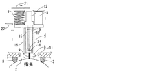
図1〜図3は、本発明のバイオセンサ用採血器の一例の構成及びその機能を模式的に表すための模式断面図であり、図1(a)、図2及び図3は、バイオセンサチップ本体に平行な面で切った断面を表し、図1(b)は、バイオセンサチップ本体に垂直な面で切った断面(図1(a)におけるAAの断面)を表す。 1 to 3 are schematic cross-sectional views for schematically illustrating the configuration and functions of an example of a blood collecting device for a biosensor of the present invention. FIGS. 1 (a), 2 and 3 are schematic views of the biosensor. A cross section cut by a plane parallel to the chip body is shown, and FIG. 1B shows a cross section cut by a plane perpendicular to the biosensor chip body (cross section AA in FIG. 1A).
図1〜図3中、1は採血器であり、2は被検査体当接口であり、3は被検査体当接口を囲むように設けられた位置決め用円筒であり、被検査体(指先)がここに当接されている。4はセンサチップであり、センサチップ4は、バイオセンサチップ本体15を含み、さらに弾性体8、穿刺針11、ケーシング16、穿刺針固定用具17、一対の電極19(対極、作用極からなるが、一方のみ図示されている。)等から構成されている。
1 to 3, 1 is a blood collection device, 2 is a test object contact port, 3 is a positioning cylinder provided so as to surround the test object contact port, and a test object (fingertip) Is abutted here.
弾性体8は、弾性材料からなる中実の成形体であり、センサチップ4の先端部に設けられている。弾性体8は、採取した血液試料を吸引するための試料導入孔9を有する。試料導入孔9は、両端に開口部を有する貫通孔であり、先端側の開口が採血口10となっている。又、試料導入孔9内には穿刺針11が収納されている。
The
バイオセンサチップ本体15は、プラスティック製のフィルム13からなり、その一端側に中空の反応部18を有し、反応部18の開口部は試料導入孔9の開口部と接しており、従って、試料導入孔9と反応部18は連通している。一対の電極19は、プラスティック製のフィルム13内に設けられるが、その一端側は反応部18内に露出しており、又他端側も露出しており、測定時には後述するコネクター12の端子22と接続される。電極19の一方には、反応を促進するための薬剤24(酵素等)が塗布されている。
The
バイオセンサチップ本体15は、プラスティック製のフィルム13からなるので、外力により変形しやすい。そこで、ケーシング16内に収納され保持される。又、穿刺針11は、穿刺針固定用具17の先端に固着されており、この穿刺針固定用具17はケーシング16内に収納され保持され、穿刺針11の固定がされる。ケーシング16は、バイオセンサチップ本体15の形状を保持し、穿刺針固定用具17を収納し固定するものなので、剛性の高い樹脂等により形成される。同様に、穿刺針固定用具17も穿刺針11を固定するものなので、剛性の高い樹脂等により形成される。又、弾性体8は、ケーシング16の先端に設けられている。
Since the
測定時には、センサチップ4(バイオセンサチップ本体15)の一端は、コネクター12の装着部23にかん合され、コネクター12とセンサチップ4は一体となって、被検査体当接口2方向及びその逆方向に移動可能に設けられている。コネクター12は、データ処理部に電気的に接続されている端子22を有し、前記のように、電極19の一端と接続される。図中、6は穿刺用バネであり、5はエアダンパである。
At the time of measurement, one end of the sensor chip 4 (biosensor chip main body 15) is engaged with the mounting
図1は、穿刺前の状態を示す。このとき、穿刺用バネ6は圧縮されており、ストッパ20によりロックされている。一方、エアダンパ5は自然長の状態であり、いずれの方向にも付勢力を生じていない。採血器1内には、さらに引き上げ位置規制用ストッパ21が設けられているが、図1の場合、すなわち穿刺前では、コネクター12の側面に接しており、バネ(図示されていない)の力によりコネクター12の側面方向に付勢されている。
FIG. 1 shows a state before puncturing. At this time, the puncture spring 6 is compressed and locked by the
図2は、センサチップ4を押圧して指先を穿刺した様子を示している。ストッパ20を、図1中の矢印の方向に動かしてロックを解除し、穿刺用バネ6の圧縮状態を解放すると、穿刺用バネ6の付勢力によりコネクター12を押圧し、コネクター12及びそれに保持されたセンサチップ4を被検査体当接口2の方向(図中の下方向)に急速に移動させる。
FIG. 2 shows a state in which the
この移動により、弾性体8は指先を押圧するようになるが、この押圧により弾性体8は図2に示すように圧縮変形し、試料導入孔9内に収納されていた穿刺針11は突出して指先を穿刺する。一方、エアダンパ5は伸長されて、コネクター12及びそれに保持されたセンサチップ4を引き上げる方向(図中の上方)に付勢力を生じる。又、コネクター12の移動に伴い、引き上げ位置規制用ストッパ21は、コネクター12の側面より外れて、バネ(図示されていない)の力により図2中に示す矢印の方向に移動する。
By this movement, the
図3は、穿刺後、穿刺針11を指先から引き抜いた後の様子を示している。穿刺後、エアダンパ5の付勢力及び圧縮変形されていた弾性体8の復元力により、センサチップ4は引き上げられ、穿刺針11は指先から引き抜かれる。その結果、穿刺部から血液が流出する。
FIG. 3 shows a state after the
このとき、図3に示すように、引き上げ位置規制用ストッパ21により、センサチップ3の引き上げ距離は規制され、採血口10と指先との間隔は一定の大きさLに保たれる。引き上げ位置規制用ストッパ21の位置は、引き上げ位置調整手段(図示されていない。)により上下に変動可能であり、この調整により、採血口10と指先の間隔Lを、通常0.3mm〜0.7mmの範囲で、被験者に最適の大きさに調整することができる。
At this time, as shown in FIG. 3, the lifting distance of the
指先から流出した血液は採血口10より試料導入孔9内に導入される。試料導入孔9内は親水加工されている。採血口10と指先との間隔Lは最適の大きさに調整されているので、血液は試料導入孔9内に円滑に導入される。図3は、試料導入孔9内に、血液が導入された状態を示す。
The blood flowing out from the fingertip is introduced into the
試料導入孔9は、センサチップ4の反応部18と連通しており、血液は、該反応部18内に導入されて電極19上に塗布されている薬剤24の作用等により反応を生じ、この反応による信号が、電極19、コネクター12の端子22と通して、端子22と接続されているデータ処理部に出力され、データ処理部で処理されて得られた測定結果が表示部で表示される。
The
図4は、本発明のバイオセンサ用採血器の他の例の、弾性体部分及びその周囲を表す模式断面図である。この例のバイオセンサ用採血器も、センサチップ40の先端に弾性体80を有し、弾性体80は、試料導入孔83を有し、穿刺針84は試料導入孔83内に収納されている点では、図1〜図3に示すバイオセンサ用採血器と同じである。図中の被検査体当接口85、位置決め用円筒86や、バイオセンサ用採血器の(図示されていない)他の部分の構造や機能も同様である。しかし、図1〜図3に示すバイオセンサ用採血器では、弾性体8は弾性材料からなる中実の成形体であるのに対し、図4のバイオセンサ用採血器の弾性体80は、中実の成形体である先端部82と、中空の蛇腹部81からなる点が相違している。先端部82は、必ずしも弾性材料から形成されなくてもよい。被検査体へ弾性体80が押圧される際には、蛇腹部81が変形し、穿刺針84が突出して穿刺が行われる。又、蛇腹部81の変形により、内部の空気が圧縮され復元力が生じる。穿刺後の、引き上げや試料の導入も、図1〜図3に示すバイオセンサ用採血器と同様に行われる。
FIG. 4 is a schematic cross-sectional view showing an elastic body portion and its periphery in another example of the blood collecting device for a biosensor of the present invention. The biosensor blood sampler of this example also has an
1 採血器
2、85 被検査体当接口
3、86 位置決め用円筒
4、40 センサチップ
5 エアダンパ
6 穿刺用バネ
8、80 弾性体
9、83 試料導入孔
10 採血口
11、84 穿刺針
12 コネクター
13 プラスティック製のフィルム
15 バイオセンサチップ本体
16 ケーシング
17 穿刺針固定用具
18 反応部
19 一対の電極
20 ストッパ
21 引き上げ位置規制用ストッパ
22 端子
23 装着部
81 蛇腹部
82 先端部
DESCRIPTION OF
Claims (4)
被検査体当接口、
前記穿刺針により、被検査体を穿刺するための穿刺手段、
穿刺後、前記針一体型センサチップを引き上げるための引き上げ手段、及び
引き上げの距離を規制し、かつ引き上げ距離の調節が可能な引き上げ規制手段、
を有することを特徴とするバイオセンサ用採血器。 An elastic body having a sample introduction hole, and a puncture needle housed in the sample introduction hole is a blood collection device for a biosensor using a needle integrated sensor chip provided at one end thereof,
Inspection object contact port,
Puncturing means for puncturing the object to be examined by the puncture needle,
A lifting means for lifting the needle-integrated sensor chip after puncturing, and a lifting regulating means for regulating the lifting distance and adjusting the lifting distance;
A blood collection device for a biosensor, comprising:
Priority Applications (1)
| Application Number | Priority Date | Filing Date | Title |
|---|---|---|---|
| JP2007191904A JP2009028062A (en) | 2007-07-24 | 2007-07-24 | Blood sampling device for biosensor and sensor chip measuring apparatus |
Applications Claiming Priority (1)
| Application Number | Priority Date | Filing Date | Title |
|---|---|---|---|
| JP2007191904A JP2009028062A (en) | 2007-07-24 | 2007-07-24 | Blood sampling device for biosensor and sensor chip measuring apparatus |
Publications (1)
| Publication Number | Publication Date |
|---|---|
| JP2009028062A true JP2009028062A (en) | 2009-02-12 |
Family
ID=40399290
Family Applications (1)
| Application Number | Title | Priority Date | Filing Date |
|---|---|---|---|
| JP2007191904A Pending JP2009028062A (en) | 2007-07-24 | 2007-07-24 | Blood sampling device for biosensor and sensor chip measuring apparatus |
Country Status (1)
| Country | Link |
|---|---|
| JP (1) | JP2009028062A (en) |
Cited By (1)
| Publication number | Priority date | Publication date | Assignee | Title |
|---|---|---|---|---|
| KR101019348B1 (en) | 2010-09-02 | 2011-03-07 | 안이솔 | Blood glucose measurement system |
-
2007
- 2007-07-24 JP JP2007191904A patent/JP2009028062A/en active Pending
Cited By (1)
| Publication number | Priority date | Publication date | Assignee | Title |
|---|---|---|---|---|
| KR101019348B1 (en) | 2010-09-02 | 2011-03-07 | 안이솔 | Blood glucose measurement system |
Similar Documents
| Publication | Publication Date | Title |
|---|---|---|
| JP4336061B2 (en) | System for drawing body fluid | |
| JP4772263B2 (en) | Cap for lancing device | |
| JP4647898B2 (en) | Body fluid sample capture test apparatus and cartridge | |
| US6099484A (en) | Methods and apparatus for sampling and analyzing body fluid | |
| US6352514B1 (en) | Methods and apparatus for sampling and analyzing body fluid | |
| JP2004522500A5 (en) | ||
| JP2003533323A (en) | Body fluid collection system | |
| KR20040002562A (en) | Sensor with intergrated lancet | |
| JP4312559B2 (en) | Sensor built-in needle, sample collection device, and sample inspection system | |
| JP2005305157A (en) | Apparatus for extracting bodily fluid | |
| JP2004528936A (en) | Blood sampling apparatus and method | |
| JP2007159658A (en) | Blood collecting needle | |
| JPWO2007088875A1 (en) | Lancet | |
| JP4953139B2 (en) | Biosensor chip | |
| JPWO2007063828A1 (en) | Body fluid collection device and method | |
| JP2009028062A (en) | Blood sampling device for biosensor and sensor chip measuring apparatus | |
| KR20170110279A (en) | Method, apparatus of bleeding using by adsorption | |
| JP2007130451A (en) | Blood sensor, blood examination device, and method for controlling blood examination device | |
| JP2007159659A (en) | Hollow needle for blood sampling | |
| US8172866B2 (en) | Medical aid | |
| JP2005283366A (en) | Micro sampling instrument for bodily fluid of living body | |
| JP4958291B2 (en) | Sensor chip measuring device | |
| JP4894038B2 (en) | Biosensor cartridge | |
| JP2009022517A (en) | Puncture device | |
| JP2007159657A (en) | Puncturing needle for blood sampling |