JP2009021908A - Motion picture encoder, and program - Google Patents
Motion picture encoder, and program Download PDFInfo
- Publication number
- JP2009021908A JP2009021908A JP2007184012A JP2007184012A JP2009021908A JP 2009021908 A JP2009021908 A JP 2009021908A JP 2007184012 A JP2007184012 A JP 2007184012A JP 2007184012 A JP2007184012 A JP 2007184012A JP 2009021908 A JP2009021908 A JP 2009021908A
- Authority
- JP
- Japan
- Prior art keywords
- vector
- parity
- picture
- encoding
- coding
- Prior art date
- Legal status (The legal status is an assumption and is not a legal conclusion. Google has not performed a legal analysis and makes no representation as to the accuracy of the status listed.)
- Granted
Links
Images


Classifications
-
- H—ELECTRICITY
- H04—ELECTRIC COMMUNICATION TECHNIQUE
- H04N—PICTORIAL COMMUNICATION, e.g. TELEVISION
- H04N19/00—Methods or arrangements for coding, decoding, compressing or decompressing digital video signals
- H04N19/85—Methods or arrangements for coding, decoding, compressing or decompressing digital video signals using pre-processing or post-processing specially adapted for video compression
- H04N19/86—Methods or arrangements for coding, decoding, compressing or decompressing digital video signals using pre-processing or post-processing specially adapted for video compression involving reduction of coding artifacts, e.g. of blockiness
-
- H—ELECTRICITY
- H04—ELECTRIC COMMUNICATION TECHNIQUE
- H04N—PICTORIAL COMMUNICATION, e.g. TELEVISION
- H04N19/00—Methods or arrangements for coding, decoding, compressing or decompressing digital video signals
- H04N19/10—Methods or arrangements for coding, decoding, compressing or decompressing digital video signals using adaptive coding
- H04N19/102—Methods or arrangements for coding, decoding, compressing or decompressing digital video signals using adaptive coding characterised by the element, parameter or selection affected or controlled by the adaptive coding
- H04N19/103—Selection of coding mode or of prediction mode
- H04N19/107—Selection of coding mode or of prediction mode between spatial and temporal predictive coding, e.g. picture refresh
-
- H—ELECTRICITY
- H04—ELECTRIC COMMUNICATION TECHNIQUE
- H04N—PICTORIAL COMMUNICATION, e.g. TELEVISION
- H04N19/00—Methods or arrangements for coding, decoding, compressing or decompressing digital video signals
- H04N19/10—Methods or arrangements for coding, decoding, compressing or decompressing digital video signals using adaptive coding
- H04N19/102—Methods or arrangements for coding, decoding, compressing or decompressing digital video signals using adaptive coding characterised by the element, parameter or selection affected or controlled by the adaptive coding
- H04N19/103—Selection of coding mode or of prediction mode
- H04N19/109—Selection of coding mode or of prediction mode among a plurality of temporal predictive coding modes
-
- H—ELECTRICITY
- H04—ELECTRIC COMMUNICATION TECHNIQUE
- H04N—PICTORIAL COMMUNICATION, e.g. TELEVISION
- H04N19/00—Methods or arrangements for coding, decoding, compressing or decompressing digital video signals
- H04N19/10—Methods or arrangements for coding, decoding, compressing or decompressing digital video signals using adaptive coding
- H04N19/102—Methods or arrangements for coding, decoding, compressing or decompressing digital video signals using adaptive coding characterised by the element, parameter or selection affected or controlled by the adaptive coding
- H04N19/103—Selection of coding mode or of prediction mode
- H04N19/11—Selection of coding mode or of prediction mode among a plurality of spatial predictive coding modes
-
- H—ELECTRICITY
- H04—ELECTRIC COMMUNICATION TECHNIQUE
- H04N—PICTORIAL COMMUNICATION, e.g. TELEVISION
- H04N19/00—Methods or arrangements for coding, decoding, compressing or decompressing digital video signals
- H04N19/10—Methods or arrangements for coding, decoding, compressing or decompressing digital video signals using adaptive coding
- H04N19/134—Methods or arrangements for coding, decoding, compressing or decompressing digital video signals using adaptive coding characterised by the element, parameter or criterion affecting or controlling the adaptive coding
- H04N19/157—Assigned coding mode, i.e. the coding mode being predefined or preselected to be further used for selection of another element or parameter
- H04N19/16—Assigned coding mode, i.e. the coding mode being predefined or preselected to be further used for selection of another element or parameter for a given display mode, e.g. for interlaced or progressive display mode
-
- H—ELECTRICITY
- H04—ELECTRIC COMMUNICATION TECHNIQUE
- H04N—PICTORIAL COMMUNICATION, e.g. TELEVISION
- H04N19/00—Methods or arrangements for coding, decoding, compressing or decompressing digital video signals
- H04N19/10—Methods or arrangements for coding, decoding, compressing or decompressing digital video signals using adaptive coding
- H04N19/169—Methods or arrangements for coding, decoding, compressing or decompressing digital video signals using adaptive coding characterised by the coding unit, i.e. the structural portion or semantic portion of the video signal being the object or the subject of the adaptive coding
- H04N19/17—Methods or arrangements for coding, decoding, compressing or decompressing digital video signals using adaptive coding characterised by the coding unit, i.e. the structural portion or semantic portion of the video signal being the object or the subject of the adaptive coding the unit being an image region, e.g. an object
- H04N19/176—Methods or arrangements for coding, decoding, compressing or decompressing digital video signals using adaptive coding characterised by the coding unit, i.e. the structural portion or semantic portion of the video signal being the object or the subject of the adaptive coding the unit being an image region, e.g. an object the region being a block, e.g. a macroblock
-
- H—ELECTRICITY
- H04—ELECTRIC COMMUNICATION TECHNIQUE
- H04N—PICTORIAL COMMUNICATION, e.g. TELEVISION
- H04N19/00—Methods or arrangements for coding, decoding, compressing or decompressing digital video signals
- H04N19/10—Methods or arrangements for coding, decoding, compressing or decompressing digital video signals using adaptive coding
- H04N19/189—Methods or arrangements for coding, decoding, compressing or decompressing digital video signals using adaptive coding characterised by the adaptation method, adaptation tool or adaptation type used for the adaptive coding
- H04N19/196—Methods or arrangements for coding, decoding, compressing or decompressing digital video signals using adaptive coding characterised by the adaptation method, adaptation tool or adaptation type used for the adaptive coding being specially adapted for the computation of encoding parameters, e.g. by averaging previously computed encoding parameters
- H04N19/197—Methods or arrangements for coding, decoding, compressing or decompressing digital video signals using adaptive coding characterised by the adaptation method, adaptation tool or adaptation type used for the adaptive coding being specially adapted for the computation of encoding parameters, e.g. by averaging previously computed encoding parameters including determination of the initial value of an encoding parameter
-
- H—ELECTRICITY
- H04—ELECTRIC COMMUNICATION TECHNIQUE
- H04N—PICTORIAL COMMUNICATION, e.g. TELEVISION
- H04N19/00—Methods or arrangements for coding, decoding, compressing or decompressing digital video signals
- H04N19/50—Methods or arrangements for coding, decoding, compressing or decompressing digital video signals using predictive coding
- H04N19/503—Methods or arrangements for coding, decoding, compressing or decompressing digital video signals using predictive coding involving temporal prediction
- H04N19/51—Motion estimation or motion compensation
- H04N19/55—Motion estimation with spatial constraints, e.g. at image or region borders
-
- H—ELECTRICITY
- H04—ELECTRIC COMMUNICATION TECHNIQUE
- H04N—PICTORIAL COMMUNICATION, e.g. TELEVISION
- H04N19/00—Methods or arrangements for coding, decoding, compressing or decompressing digital video signals
- H04N19/60—Methods or arrangements for coding, decoding, compressing or decompressing digital video signals using transform coding
- H04N19/61—Methods or arrangements for coding, decoding, compressing or decompressing digital video signals using transform coding in combination with predictive coding
Landscapes
- Engineering & Computer Science (AREA)
- Multimedia (AREA)
- Signal Processing (AREA)
- Computing Systems (AREA)
- Theoretical Computer Science (AREA)
- Compression Or Coding Systems Of Tv Signals (AREA)
- Color Television Systems (AREA)
Abstract
Description
本発明は、フィールドで構成される動画像の、フィールド内予測符号化及びフィールド間予測符号化を行う動画像符号化装置に関する。 The present invention relates to a moving picture coding apparatus that performs intra-field predictive coding and inter-field predictive coding of a moving picture composed of fields.
動画像データは、一般に、データ量が大きいので、送信装置から受信装置へ伝送される際、あるいは記憶装置に格納される際などには、高能率符号化が行われる。ここで、「高能率符号化」とは、あるデータ列を他のデータ列に変換する符号化処理であって、そのデータ量を圧縮する処理をいう。 Since moving image data generally has a large amount of data, high-efficiency encoding is performed when it is transmitted from a transmission device to a reception device or stored in a storage device. Here, “high-efficiency encoding” refers to an encoding process for converting a data string into another data string and compressing the data amount.
代表的な動画像符号化方式として、ISO/IEC MPEG-2/MPEG-4(以下MPEG-2、MPEG-4と称す)が挙げられる。このような動画像符号化方式を用いてリアルタイム通信を行う場合、符号化から受信側での再生迄の時間を短くすることが必要であり、送信側での符号化と受信側での復号化における遅延を少なくする低遅延化を実現する必要がある。 As a typical moving image encoding method, there is ISO / IEC MPEG-2 / MPEG-4 (hereinafter referred to as MPEG-2, MPEG-4). When real-time communication is performed using such a moving image encoding method, it is necessary to shorten the time from encoding to reproduction on the reception side, and encoding on the transmission side and decoding on the reception side are necessary. Therefore, it is necessary to realize a low delay that reduces the delay in.
以下に、特許文献1に基づくMPEG-2の低遅延符号化方式について説明する。MPEG-2は、I,P,Bの3種類のピクチャを規定している。Iピクチャは他のピクチャの符号化画像及び、予測を使用せず、自ピクチャ内の情報のみで画像を復元できる(フレーム内符号化)ピクチャである。Pピクチャは過去のピクチャから順方向のピクチャ間予測を行い、予測誤差を符号化(フレーム間符号化)したピクチャである。Bピクチャは過去と未来のピクチャから双方向のピクチャ間予測を行い、その予測誤差を符号化(フレーム間符号化)したピクチャである。Bピクチャは未来のピクチャを予測に用いるため、その符号化に先駆けて、予測に用いられる未来のピクチャを符号化する必要がある。そこで、符号化順にピクチャの並び替えを行う処理が必要となる。 The MPEG-2 low delay encoding method based on Patent Document 1 will be described below. MPEG-2 defines three types of pictures: I, P, and B. An I picture is a picture that can be restored using only the information in the own picture without using the encoded picture of other pictures and prediction (intra-frame coding). A P picture is a picture obtained by performing inter-picture prediction in the forward direction from a past picture and coding a prediction error (inter-frame coding). A B picture is a picture obtained by performing bidirectional inter-picture prediction from past and future pictures and coding the prediction error (inter-frame coding). Since the B picture uses the future picture for prediction, it is necessary to encode the future picture used for prediction prior to the encoding. Therefore, processing for rearranging pictures in the encoding order is required.
ここで低遅延を実現するための方式では、ピクチャの並び替えの(未来のピクチャを現ピクチャの予測のために先に処理することによる)遅延を省くためにBピクチャを使用しない。 Here, in the method for realizing the low delay, the B picture is not used in order to eliminate the delay of the rearrangement of the pictures (by processing the future picture first for the prediction of the current picture).
また、動画像符号化の処理単位はピクチャを16×16画素のブロック(マクロブロック)で行われる。マクロブロックタイプとしては、ピクチャ内符号化を行うイントラマクロブロックと、ピクチャ間符号化を行うインターマクロブロックがある。 In addition, the processing unit of moving image coding is performed by using a block of 16 × 16 pixels (macroblock) as a picture. The macroblock type includes an intra macroblock that performs intra-picture encoding and an inter macroblock that performs inter-picture encoding.
このような動画像の符号化にて低遅延を実現するためには、あるマクロブロックを水平方向に並べたマクロブロックライン(スライス)内のデータをすべて、イントラマクロブロックとして符号化するイントラスライスを用い、イントラスライスを適用するマクロブロックラインの位置をピクチャごとにずらしていくことで、一定周期でピクチャ全体をイントラスライスが巡回するため、ピクチャ全体をリフレッシュすることが可能となる。このようなリフレッシュ方法により基本的なにはピクチャをPピクチャのみの構成とし、Iピクチャを用いないことで、バッファサイズを減少させることができ、バッファによる遅延を軽減することができる。 In order to realize a low delay by encoding such a moving image, an intra slice for encoding all data in a macro block line (slice) in which a certain macro block is arranged in the horizontal direction as an intra macro block is used. By using and shifting the position of the macro block line to which the intra slice is applied for each picture, the intra slice circulates the entire picture at a constant period, so that the entire picture can be refreshed. By such a refresh method, the picture is basically composed only of P pictures and no I pictures are used, so that the buffer size can be reduced and the delay caused by the buffers can be reduced.
しかし、この際、Pピクチャのイントラスライス以外のスライスのマクロブロックが制限なくベクトルを用いて動き補償を行うと、イントラスライスがピクチャ全体を巡回しても、イントラスライスによるリフレッシュ後のマクロブロックがイントラリフレッシュ前の位置の画像を参照することにより、参照先にてエラーが発生していた場合にエラーが空間方向に伝播してしまい、最悪の場合、エラーが画面に残り続けてしまう、というおそれがある。この問題を解決するため、特許文献2では、イントラスライスで符号化が行われたスライスについて、あらかじめ定められた時間だけ、非ゼロの動きベクトルを用いた動き補償を禁止することにより、エラーが伝播しない方法が開示されている。
背景度術で説明した特許文献1及び特許文献2のイントラスライスと動きベクトル制限を行う方式を動画像符号化の国際標準ITU-T H.264(以下 H.264)に適用しようとする場合、H.264の符号化方式固有の問題のため、エラーの空間方向への伝播が防げない、という問題があった。以下に、MPEG-2とH.264の符号化方式の相違とH.264固有の課題について説明する。 When applying the intra-slice and motion vector restriction methods of Patent Document 1 and Patent Document 2 described in Background Art to the international standard ITU-T H.264 (hereinafter referred to as H.264) of video coding, There was a problem that the propagation of errors in the spatial direction could not be prevented due to a problem specific to the H.264 encoding method. In the following, differences between MPEG-2 and H.264 encoding methods and problems unique to H.264 will be described.
MPEG-2では、イントラスライスを生成する場合、スライスヘッダ上にIntraSliceというシンタックスが存在するため、このフラグをオンにすることで指定されたスライスを構成するマクロブロックがすべてイントラマクロブロックで構成することを指定できる。しかしながら、H.264ではこのシンタックスが存在しないため、イントラスライスを生成することができない。これをイントラスライス問題と呼ぶことにする。 In MPEG-2, when an intra slice is generated, there is a syntax called IntraSlice on the slice header. Therefore, all macroblocks that constitute the specified slice by turning this flag on are composed of intra macroblocks. Can be specified. However, since this syntax does not exist in H.264, an intra slice cannot be generated. This is called the intra slice problem .
次にMPEG-2のイントラマクロブロックの生成方式は、マクロブロックを8×8のサブブロックに分割し、そこに含まれる画素にDCT(離散コサイン変換)を行っているのに対し、H.264のイントラマクロブロックの生成方式では複数モードの画面内予測符号化によってブロック間の画素相関を用いる方式を採用することによりさらに圧縮率を向上している。すなわち、イントラマクロブロックの符号化においても符号化対象ブロックの周辺画素から予測画像を作成し、予測画像との差である予測誤差に直交変換を行っている。ここで、MPEG-2においてイントスライスを用いた場合、イントラマクロブロックラインの上下でスライス分割を行うことになるが、イントラ予測効率は、イントラ符号化が予測を用いないため、スライス分割に関係なく一定となる。しかしながら、H.264では、イントラ符号化に周辺画素からの予測を用いた符号化を行うことが可能であり、イントラマクロブロックラインの上下でスライス分割を行うと、規格上スライスを跨いだ周辺画素からの予測画像作成は禁止されているため、周辺画素からの予測で例えば上方から予測を行う予測モードが制限を受けることになる。この場合、イントラ予測効率は、スライス分割によって減少してしまう。これをイントラ予測効率問題と呼ぶことにする。 Next, the MPEG-2 intra-macroblock generation method divides the macroblock into 8 × 8 sub-blocks and performs DCT (Discrete Cosine Transform) on the pixels included therein, whereas H.264 In the intra-macroblock generation method, the compression rate is further improved by adopting a method that uses pixel correlation between blocks by intra-frame predictive coding in a plurality of modes. That is, also in the encoding of an intra macroblock, a prediction image is created from the surrounding pixels of the encoding target block, and orthogonal transformation is performed on a prediction error that is a difference from the prediction image. Here, when an intra slice is used in MPEG-2, slice division is performed above and below the intra macroblock line. However, since intra coding does not use prediction, intra prediction efficiency is independent of slice division. It becomes constant. However, in H.264, it is possible to perform encoding using prediction from neighboring pixels for intra coding, and if slice division is performed above and below the intra macroblock line, the neighboring pixels across slices according to the standard Therefore, the prediction mode in which the prediction is performed from above is limited by the prediction from the surrounding pixels. In this case, the intra prediction efficiency is reduced by slice division. This is called an intra prediction efficiency problem .
また、H.264では、ブロック歪を低減させる目的で符号化処理中のマクロブロックと周辺マクロブロック境界間でデブロッキングフィルタをかけることが規定されている。ここで、イントラマクロブロックより上の領域はリフレッシュ済の領域であり、下の領域はリフレッシュが完了していない劣化領域である。この劣化領域にあるマクロブロックとイントラマクロブロック境界でデブロッキングフィルタをかけてしまうと、劣化領域からの画素成分が、リフレッシュ領域に流れ込んでしまうためにリフレッシュ領域が劣化してしまう問題が発生する。これをデブロッキングフィルタ問題と呼ぶことにする。 Also, H.264 stipulates that a deblocking filter be applied between the macroblock being encoded and the surrounding macroblock boundary for the purpose of reducing block distortion. Here, the area above the intra macroblock is a refreshed area, and the area below is a deteriorated area where refresh has not been completed. If a deblocking filter is applied at the boundary between the macroblock and the intra macroblock in the degraded area, a pixel component from the degraded area flows into the refresh area, which causes a problem that the refresh area is degraded. This is called the deblocking filter problem .
更に、MPEG-2では、Pピクチャにおいて過去のピクチャから順方向動き予測を行う際に、過去のピクチャにおけるリフレッシュ領域からのみ動きベクトルを生成するというベクトル制限を行っている。ここでH.264において、輝度成分の動きベクトルから色差成分の動きベクトルを生成する方法が規定されている。これらは、動きベクトルの参照元フィールドと参照先フィールドのパリティに依存し、それぞれ、両フールドが同じパリティの場合、前者がトップフィールドで後者がボトムフィールドの場合、及び前者がボトムフィールドで後者がトップフィールドの場合、の3種類の場合で、計算方法が異なる。ここで、参照元がボトムフィールドで参照先がトップフィールドの場合の計算式を以下に示す。
MVCy=MVy/2+1/4
ただし、MVCyは色差ベクトルY方向成分、MVyは輝度ベクトルY方向成分である。
ここで、MVy=0のとき、MVCy=1/4となり、輝度ベクトルが、ゼロベクトルであるにもかかわらず、色差ベクトルが正のベクトルとなり、同一位置より下方を参照することとなってしまう。本来、輝度におけるゼロベクトルの位置ではリフレッシュ領域内であるため参照を許可されるはずだが、上記のように色差は下方(劣化領域)を参照してしまうために、劣化領域からの画素成分が、リフレッシュ領域に流れ込んでしまうためにリフレッシュ領域が劣化してしまう問題が発生する。これをベクトル問題と呼ぶことにする。
Further, in MPEG-2, when performing forward motion prediction from a past picture in a P picture, vector restriction is performed such that a motion vector is generated only from a refresh area in the past picture. Here, in H.264, a method for generating a color difference component motion vector from a luminance component motion vector is defined. These depend on the parity of the reference field and reference field of the motion vector. When both fields have the same parity, the former is the top field and the latter is the bottom field, and the former is the bottom field and the latter is the top. In the case of the field, the calculation method is different in the three cases. Here, the calculation formula when the reference source is the bottom field and the reference destination is the top field is shown below.
MVCy = MVy / 2 + 1/4
However, MVCy is a color difference vector Y direction component, and MVy is a luminance vector Y direction component.
Here, when MVy = 0, MVCy = 1/4, and although the luminance vector is a zero vector, the color difference vector becomes a positive vector, and the lower part is referred to from the same position. Originally, reference should be permitted because the position of the zero vector in the luminance is within the refresh area, but as described above, since the color difference refers to the lower part (degraded area), the pixel component from the degraded area is There is a problem that the refresh area deteriorates because it flows into the refresh area. This is called a vector problem .
本発明の目的は、以上の問題を解決し、動画符号化方式H.264を用いた低遅延符号化を実現する動画像符号化装置を提供することである。
An object of the present invention is to provide a moving picture coding apparatus that solves the above problems and realizes low-delay coding using the moving picture coding method H.264.
本発明は、上述した課題を解決するために以下の構成を採用する。すなわち、本発明は、フィールド符号化モードを用いた動画像符号化装置において、強制イントラブロックライン位置を決定する強制イントラブロックライン決定手段と、強制イントラブロックライン位置で、強制的にイントラ符号化を選択するイントラ選択手段と、現フィールドの任意のブロックラインでベクトル制限ブロックライン位置を決定するベクトル制限ブロックライン決定手段と、ベクトル制限ブロックライン位置で、インター符号化の参照フィールド及び参照領域を強制的に制限するベクトル制限手段と、イントラ選択手段においてイントラ符号化を選択したブロックラインの1つ下のブロックラインを境界として強制的にスライス分割を行うスライス分割手段と、スライス分割手段がスライス分割を行ったブロックラインを跨いで行われるデブロッキングフィルタ処理を強制的に禁止するデブロッキングフィルタ禁止手段とを備えている。 The present invention employs the following configuration in order to solve the above-described problems. That is, the present invention provides a compulsory intra block line determination means for determining a compulsory intra block line position and a compulsory intra block line position for compulsory intra coding in a moving picture coding apparatus using a field coding mode. Intra selection means for selection, vector restriction block line determination means for determining a vector restricted block line position at an arbitrary block line in the current field, and a reference field and reference area for inter coding are forced at the vector restricted block line position Vector limiting means for limiting the number of slices, slice dividing means for forcibly performing slice division with the block line immediately below the block line selected for intra coding by the intra selection means, and the slice dividing means for performing slice division Block line And a deblocking filter inhibiting means for forcibly prohibit deblocking filter processing performed by the household.
本発明に係る動画像符号化装置では、前記強制イントラブロックライン決定手段が、現フィールドのパリティと前回の強制イントラブロックライン位置を入力として、パリティがボトムフィールドの場合、前回の強制イントラブロックライン位置の1つ下のラインを現強制イントラブロックライン位置とする手段を備えている。 In the video encoding device according to the present invention, when the forced intra block line determination means receives the current field parity and the previous forced intra block line position as input, and the parity is the bottom field, the previous forced intra block line position. Means for setting the line immediately below the current forced intra block line position.
本発明に係る動画像符号化装置では、前記ベクトル制限ブロックライン決定手段が、前回の強制イントラブロックライン位置を入力として、前回の強制イントラブロックライン位置と同一位置のラインをベクトル制限ブロックライン位置とする手段を備えている。 In the video encoding device according to the present invention, the vector restricted block line determination means receives the previous forced intra block line position as an input, and sets a line at the same position as the previous forced intra block line position as the vector restricted block line position. Means to do.
本発明に係る動画像符号化装置では、前記イントラ選択手段は、前記強制イントラブロックライン決定手段に従って、前記強制イントラブロックライン位置に含まれるマクロブロックに対して強制的にイントラ符号化を選択する手段を備えている。 In the moving picture coding apparatus according to the present invention, the intra selection means forcibly selects intra coding for a macroblock included in the forced intra block line position according to the forced intra block line determination means. It has.
本発明に係る動画像符号化装置では、前記ベクトル制限手段は、現フィールドのパリティと参照フィールドのパリティと参照フィールドのスライス分割位置とベクトル制限ブロックライン位置を入力として、ベクトル制限ブロックライン位置より上のブロックにおいて、参照フィールドのスライス分割位置より上方のみを参照可能とするベクトル制限と、現フィールドのパリティがボトムフィールドかつ参照フィールドのパリティがトップフィールドである場合、ベクトル制限ブロックライン位置と同一位置にある参照フィールドのブロックラインを参照不可とするベクトル制限を行う手段を備えている。 In the moving picture coding apparatus according to the present invention, the vector restriction means receives the parity of the current field, the parity of the reference field, the slice division position of the reference field, and the vector restricted block line position as input, and is above the vector restricted block line position. In this block, when the vector restriction that allows reference only above the slice division position of the reference field and the parity of the current field is the bottom field and the parity of the reference field is the top field, the block is located at the same position as the vector restriction block line position. Means is provided for performing a vector restriction that disables reference to a block line of a reference field.
本発明に係る動画像符号化装置では、前記スライス分割手段は、現フィールドのパリティと強制イントラブロックライン位置とベクトル制限ブロックライン位置を入力として、現フィールドのパリティがトップフィールドの場合、ベクトル制限ブロックライン位置とその1つ下のブロックラインとを境界としてスライス分割を行い、現フィールドのパリティがボトムフィールドの場合、強制イントラブロックライン位置とその1つ下のブロックラインとを境界としてスライス分割を行う手段を備えている。
なお、本発明は、以上の機能を実現させるプログラムであってもよい。
In the moving picture coding apparatus according to the present invention, the slice dividing means receives the parity of the current field, the forced intra block line position, and the vector restricted block line position as input, and when the parity of the current field is the top field, the vector restricted block Slice division is performed with the line position and the block line immediately below as a boundary, and when the parity of the current field is the bottom field, slice division is performed with the forced intra block line position and the block line immediately below as a boundary. Means.
The present invention may be a program for realizing the above functions.
本発明によれば、複数のフィールドで構成される動画像信号を符号化する動画符号化方式(H.264)を用いた場合の低遅延化を実現する動画像符号化装置を提供することができる。
According to the present invention, it is possible to provide a moving picture coding apparatus that realizes a reduction in delay when a moving picture coding method (H.264) for coding a moving picture signal composed of a plurality of fields is used. it can.
以下、本発明の実施の形態について図1〜図15に基づいて説明する。 Hereinafter, embodiments of the present invention will be described with reference to FIGS.
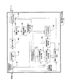
図1は、本発明の実施例に係る動画符号化装置100の全体構成について説明する図である。
図1に示すように、本実施形態における動画像符号化装置100は、予測誤差信号生成手段101、直交変換手段102、量子化手段103、エントロピー符号化手段104、逆量子化手段105、逆直交変換手段106、復号画像生成手段107、デブロッキングフィルタ手段108、復号画像記憶手段109、イントラ予測画像生成手段110、インター予測画像生成手段111、動きベクトル計算手段112、符号化制御及びヘッダ生成手段113及び予測画像選択手段114を有している。各機能部についての概略を以下に説明する。
FIG. 1 is a diagram for explaining the overall configuration of a moving picture coding apparatus 100 according to an embodiment of the present invention.
As shown in FIG. 1, the moving picture coding apparatus 100 according to the present embodiment includes a prediction error
予測誤差信号生成手段101は、入力された動画像データの現ピクチャを16×16ピクセル(画素)のブロック(以降、マクロブロック(MB)という)に分割されたマクロブロックデータ(以降、ブロックデータともいう)を得て、そのマクロブロックデータと、予測画像選択手段114から供給される予測画像ピクチャのマクロブロックデータとにより、予測誤差信号を生成する。予測誤差信号生成手段101は、生成された予測誤差信号を直交変換手段102に渡す。
The prediction error signal generation means 101 is a macroblock data (hereinafter referred to as block data) obtained by dividing the current picture of the input moving image data into 16 × 16 pixel (pixel) blocks (hereinafter referred to as macroblocks (MB)). And a prediction error signal is generated from the macroblock data and the macroblock data of the predicted image picture supplied from the predicted
直交変換手段102は、入力された予測誤差信号を直交変換処理する。直交変換手段102は、直交変換処理によって水平及び垂直方向の周波数成分に分離された信号を量子化手段103に供給する。量子化手段103は、直交変換手段102の出力を量子化する。量子化手段103は、符号化することによって当該予測誤差信号の符号量を低減し、エントロピー符号化手段104及び逆量子化手段105に供給する。
The
エントロピー符号化手段104は、量子化手段103からの出力をエントロピー符号化(可変長符号化)して出力する。エントロピー符号化とは、シンボルの出現頻度に応じて可変長の符号を割り当てる方式をいう。
The
逆量子化手段105は、量子化手段103の出力を逆量子化してから逆直交変換手段106に供給する。逆直交変換手段106は、逆量子化手段105の出力を逆直交変換処理してから復号画像生成手段107に供給する。これら逆量子化手段105及び逆直交変換手段106によって復号化処理が行われることにより、符号化前の予測誤差信号と同程度の信号が得られる。
The inverse quantization means 105 dequantizes the output of the quantization means 103 and then supplies it to the inverse orthogonal transform means 106. The inverse
復号画像生成手段107は、インター予測画像生成手段111で動き補償されたピクチャのブロックデータと、逆量子化手段105、及び逆直交変換手段106により復号処理された予測誤差信号とを加算することにより、現画像データピクチャの予測されるブロックデータを再生し、デブロッキングフィルタ手段108に渡す。
The decoded
デブロッキングフィルタ手段108は、復号画像生成手段107の出力である復号画像に対し、ブロック歪を低減するためのフィルタをかけ、復号画像記憶手段109に渡す。
The
復号画像記憶手段109は、渡されたブロックデータを新たな参照ピクチャのデータとして記憶し、イントラ予測画像生成手段110、インター予測画像生成手段111及び動きベクトル計算手段112に供給する。
The decoded
イントラ予測画像生成手段110は、同ピクチャのすでに符号化された周辺画素から予測画像を生成する。
The intra predicted
一方、インター予測画像生成手段111は、復号画像記憶手段109から得た参照ピクチャのデータを動きベクトル計算手段112から提供される動きベクトルで動き補償することにより、動き補償された参照ピクチャとしてのブロックデータを生成する。
On the other hand, the inter predicted
動きベクトル計算手段112は、現画像データピクチャにおけるブロックデータと、復号画像記憶部109から得る既に符号化された参照ピクチャのブロックデータを用いて、動きベクトルを求める。動きベクトルとは、ブロック単位で参照ピクチャから現ピクチャに最も類似している位置を探索するブロックマッチング技術を用いて求められるブロック単位の空間的なずれを示す値である。動きベクトル計算手段112は、求めた動きベクトルをインター予測画像生成手段111に渡す。
The motion vector calculation means 112 obtains a motion vector using the block data in the current image data picture and the block data of the already encoded reference picture obtained from the decoded
イントラ予測画像生成手段110とインター予測画像生成手段111から出力されたブロックデータは、予測画像選択手段114に入力され、どちらか一方の予測画像を選択することができる。選択されたブロックデータは、予測誤差信号生成手段101に供給される。
The block data output from the intra prediction
また、符号化制御及びヘッダ生成手段113について、符号化の全体制御とヘッダ生成を行う。イントラ予測画像生成手段110に対して、スライス分割有無の通知、デブロッキングフィルタ手段108に対して、デブロッキングフィルタ有無の通知、動きベクトル計算手段112に対して参照画制限通知などを行い、その制御結果を用いて、H.264のヘッダ情報を生成するものである。生成されたヘッダ情報はエントロピー符号化手段104に渡され、画像データ,動きベクトルデータとともにストリームとして出力される。
The encoding control and
本発明の機能ブロック間のデータの流れを図2に示す。図2では、符号化制御及びヘッダ生成手段201(図1の符号化制御及びヘッダ生成手段113に対応)、予測画像選択手段202(図1の予測画像選択手段114に対応)、動きベクトル計算手段203(図1の動きベクトル計算手段112に対応)に対して、以下で述べる動画像符号化方式H.264における低遅延符号化で必要な機能を備えるものである。
A data flow between the functional blocks of the present invention is shown in FIG. In FIG. 2, encoding control and header generation means 201 (corresponding to the encoding control and header generation means 113 in FIG. 1), prediction image selection means 202 (corresponding to the prediction image selection means 114 in FIG. 1), motion vector calculation means 203 (corresponding to the motion
本実施形態における符号化制御及びヘッダ生成手段201は、図2及び図3に示すように強制イントラブロックライン決定手段301とベクトル制限ブロックライン決定手段302とスライス分割手段303とデブロッキングフィルタ禁止手段304を備える。以下に、それぞれの機能について詳しく述べる。
As shown in FIGS. 2 and 3, the encoding control and
強制イントラブロックライン決定手段301は、図2及び図4に示すように現フィールドのパリティ401と前回の強制イントラブロックライン位置402を入力として、予測画像選択手段202に対し強制イントラ信号403を出力する。また、スライス分割手段303及び符号化制御及びヘッダ制御手段201に対し、強制イントラブロックライン位置404を出力する。
The forced intra block
強制イントラブロックライン決定手段301は、図5のように、現フィールドのパリティがボトムフィールドの場合、前回の強制イントラブロックライン位置501がN-1番目のラインとすると、その1つ下のNラインを現在の強制イントラブロックライン位置502とする。符号化中のマクロブロックが、強制イントラブロックライン位置502に含まれる場合、予測画像選択手段202に対し強制イントラ信号403を出力する。また、スライス分割手段303に対し、強制イントラブロックライン位置404を出力する。ただし、前回の強制イントラブロックライン位置501がピクチャの下限に達していた場合は、ピクチャの先頭ブロックラインを現在の強制イントラブロックライン位置502とする。
As shown in FIG. 5, when the parity of the current field is the bottom field, the forced intra block
ベクトル制限ブロックライン決定手段302は、図6に示すように前回の強制イントラブロックライン位置402及び現フィールドのパリティ401を入力として、動きベクトル計算手段203に対しベクトル制限ブロックライン位置602を出力する。同様に、スライス分割手段303に対し、ベクトル制限ブロックライン位置602を出力する。
ベクトル制限ブロックライン決定手段302は、図7に示すように、現ピクチャがトップフィールドの場合、前回のボトムフィールドに存在する強制イントラブロックライン位置701がN-1番目のラインとすると、現ピクチャの同一位置のN-1ラインをベクトル制限ブロックライン位置702とする。現ピクチャがボトムフィールドの場合、前回のボトムフィールドに存在する強制イントラブロックライン位置703がN-1番目のラインとすると、同一位置のN-1ラインをベクトル制限ブロックライン位置704とする。ここで、現ピクチャの符号化中のマクロブロックが、上記ベクトル制限ブロックライン位置より上にある場合、動きベクトル計算手段203に対しベクトル制限ブロックライン位置602を出力する。同様に、スライス分割手段303に対し、ベクトル制限ブロックライン位置602を出力する。
As shown in FIG. 6, the vector restricted block line determination means 302 receives the previous forced intra
As shown in FIG. 7, when the current picture is the top field, the vector restricted block line determination means 302 determines that the forced intra
スライス分割手段303は、図8に示すように現フィールドのパリティ401とベクトル制限ブロックライン位置602と強制イントラブロックライン位置404を入力として、イントラ予測画像生成手段110にスライス分割位置804を出力する。また、デブロッキングフィルタ禁止手段304及び符号化制御及びヘッダ制御手段201に対して、スライス分割位置804を出力する。
As shown in FIG. 8, the
スライス分割手段303は、図9に示すように現フィールドのパリティがトップフィールドの場合、ベクトル制限ブロックライン位置901とその1つ下のブロックラインとを境界としてスライス分割を行う。また、現フィールドのパリティがボトムフィールドの場合、強制イントラブロックライン位置903とその1つ下のブロックラインとを境界としてスライス分割を行い、イントラ予測画像生成手段にスライス分割位置902及び904を出力する。同様に、デブロッキングフィルタ禁止手段に対して、スライス分割位置902及び904を出力する。ただし、スライス分割位置902及び904がピクチャの下限に達していれば、スライス分割をする必要はない。
ここで、符号化制御及びヘッダ生成手段201において、スライス分割が発生し、デブロッキングフィルタをスライス境界にかけないという情報をH.264のヘッダ情報として生成する。正確には、H.264のスライスヘッダ情報を生成し、シンタックスであるfirst#mb#in#sliceにスライス分割位置先頭のマクロブロック番号を設定する。またdisable#deblocking#filter#idcに2(スライス境界にデブロッキングフィルタをかけない意)を設定する。
As shown in FIG. 9, when the parity of the current field is the top field, the
Here, in the encoding control and
デブロッキングフィルタ禁止手段304は、図10に示すようにスライス分割手段303で得られたスライス分割位置804を入力として、デブロッキングフィルタ手段に対し、フィルタ禁止信号1002を出力する。
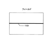
The deblocking
デブロッキングフィルタ禁止手段304は、図11に示すように符号化中のマクロブロックが、スライス分割境界1101を含む場合、デブロッキングフィルタ手段108に対し、フィルタ禁止信号1002を出力する。
The deblocking
本実施形態における予測画像選択手段202は、図12に示すようなイントラ選択手段1200を備える。イントラ選択手段1200は、スイッチ制御手段1201を備え、強制イントラブロックライン決定手段301が出力した強制イントラ信号403を入力とし、強制イントラ信号403により指示されたマクロブロックに対して強制的にイントラ予測を選択し、イントラ予測画像生成手段110の出力を受信する。
The predicted
本実施形態における動きベクトル計算手段203は、図13に示すようなベクトル制限手段1300を備える。ベクトル制限手段は、現フィールドのパリティ401と参照フィールドのパリティ1302と参照フィールドのスライス分割位置1303とベクトル制限ブロックライン位置を入力602として、インター予測画像生成手段111に対して、ベクトルデータ1305を出力する。
ベクトル制限手段1300は、図14に示すように、ベクトル制限ブロックライン位置1404を含む上方のベクトル制限対象ブロック1403において、参照フィールドのスライス分割位置1401より上方のみを参照可能とする。さらに、現フィールドのパリティがボトムフィールドかつ参照フィールドのパリティがトップフィールドである場合、ベクトル制限ブロックライン位置1404と同一位置にある参照フィールドのブロックライン1402を参照不可とする。
本実施形態における動きベクトル計算手段203は、スライス分割手段303からスライス分割位置804を受信し、スライス境界の下のマクロブロックに対し、スライス境界を越えて予測を行う予測モードを禁止する。これはH.264の規格によるものである。
本実施形態におけるデブロッキングフィルタ手段108は、デブロッキングフィルタ禁止手段304からフィルタ禁止信号1002を受信し、スライス境界を跨ぐフィルタ処理を禁止する。
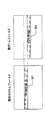
上記実施例から生成されるビットストリームの構成例を図15に示す。図15のビデオシーケンスは、ビットストリーム1500を繰り返すことで構成される。本ビットストリーム1500では、イントラスライスによるリフレッシュをボトムフィールドの画像にのみ行い、トップフィールドの参照先をボトムフィールドのリフレッシュが完了している領域とすることで、結果的にトップフィールドについてもリフレッシュを行ったと同様の作用がえられる事になる。また、このビットストリームはH.264の規格に準拠している。すなわち、H.264に対応した動画像復号装置であれば、特別な処理や装置を追加する必要がなく、ストリームの再生が可能である。
The motion vector calculation means 203 in this embodiment includes a vector restriction means 1300 as shown in FIG. The vector restricting means outputs the
As shown in FIG. 14, the
The motion
In the present embodiment, the
A configuration example of the bit stream generated from the above embodiment is shown in FIG. The video sequence in FIG. 15 is configured by repeating the
次に、発明が解決しようとする課題との関係について説明する。イントラスライス問題について、本実施例における強制イントラブロックライン決定手段301及びイントラ選択手段1200により、任意のマクロブロックラインを強制的にイントラマクロブロックで構成することによって、イントラスライスと同等のものを生成可能である。イントラ予測効率問題について、本実施例におけるスライス分割手段303により、スライス境界を強制イントラブロックライン位置の下に設定することによって、強制イントラブロックラインに含まれるイントラマクロブロックについては、予測モードの制限を受けることはない。デブロッキングフィルタ問題について、デブロッキングフィルタ禁止手段304により、スライス境界を跨ぐフィルタ処理を禁止することで、劣化領域からの画素成分が、リフレッシュ領域に流れ込むのを防いでいる。ベクトル問題について、本実施例におけるベクトル制限ブロックライン決定手段302及びベクトル制限手段1300により、現フィールドのパリティがボトムフィールドかつ参照フィールドのパリティがトップフィールドである場合、問題となる領域を参照不可とすることにより、劣化領域からの画素成分が、リフレッシュ領域に流れ込むのを防いでいる。
以上に説明したように、動画符号化方式H.264を用いた低遅延符号化を実現する動画像符号化装置を提供することができる。
Next, the relationship with the problem to be solved by the invention will be described. With respect to the intra slice problem, the compulsory intra block
As described above, it is possible to provide a moving picture coding apparatus that realizes low-delay coding using the moving picture coding method H.264.
また、以上で説明した直交変換手段は離散コサイン変換等の同等の処理が可能な代替可能であり、エントロピー符号化手段も可変長符号化,算術符号化等同等な機能を実現可能なものと代替可能である。
Further, the orthogonal transform means described above can be replaced with an equivalent process such as discrete cosine transform, and the entropy encoding means can be replaced with a function capable of realizing an equivalent function such as variable length coding and arithmetic coding. Is possible.
100 動画像符号化装置
101 予測誤差信号生成手段
102 直交変換手段
103 量子化手段
104 エントロピー符号化手段
105 逆量子化手段
106 逆直交変換手段
107 復号画像生成手段
108 デブロッキングフィルタ手段
109 復号画像記憶手段
110 イントラ予測画像生成手段
111 インター予測画像生成手段
112 動きベクトル計算手段
113 符号化制御及びヘッダ生成手段
114 予測画像選択手段
201 符号化制御及びヘッダ生成手段
202 予測画像選択手段
203 動きベクトル計算手段
301 強制イントラブロックライン決定手段
302 ベクトル制限ブロックライン決定手段
303 スライス分割手段
304 デブロッキングフィルタ禁止手段
401 現フィールドのパリティ
402 前回の強制イントラブロックライン位置
403 強制イントラ信号
404 強制イントラブロックライン位置
501 前回の強制イントラブロックライン位置
502 現在の強制イントラブロックライン位置
602 ベクトル制限ブロックライン位置
701 前回の強制イントラブロックライン位置
702 トップフィールドベクトル制限ブロックライン位置
703 前回の強制イントラブロックライン位置
704 トップフィールドベクトル制限ブロックライン位置
804 スライス分割位置
901 ベクトル制限ブロックライン位置
902 トップフィールドスライス分割位置
903 強制イントラブロックライン位置
904 ボトムフィールドスライス分割位置
1002 フィルタ禁止信号
1101 デブロッキングフィルタ禁止位置
1200 イントラ選択手段
1201 スイッチ制御手段
1300 ベクトル制限手段
1302 参照フィールドのパリティ
1303 参照フィールドのスライス分割位置
1305 ベクトルデータ
1401 参照フィールドのスライス分割位置
1402 参照不可である参照フィールドのブロックライン
1403 ベクトル制限対象ブロック
1404 ベクトル制限ブロックライン位置
1500 ビットストリーム
DESCRIPTION OF SYMBOLS 100 Moving image encoding apparatus 101 Prediction error signal generation means 102 Orthogonal transformation means 103 Quantization means 104 Entropy encoding means 105 Inverse quantization means 106 Inverse orthogonal transformation means 107 Decoded image generation means 108 Deblocking filter means 109 Decoded image storage means 110 Intra Prediction Image Generation Unit 111 Inter Prediction Image Generation Unit 112 Motion Vector Calculation Unit 113 Coding Control and Header Generation Unit 114 Prediction Image Selection Unit 201 Encoding Control and Header Generation Unit 202 Prediction Image Selection Unit 203 Motion Vector Calculation Unit 301 Forcing Intra block line determining means 302 Vector restricted block line determining means 303 Slice dividing means 304 Deblocking filter prohibiting means 401 Parity of current field 402 Previous forced intra block line Position 403 Forced intra signal 404 Forced intra block line position 501 Previous forced intra block line position 502 Current forced intra block line position 602 Vector restricted block line position 701 Previous forced intra block line position 702 Top field vector restricted block line position 703 Previous forced intra block line position 704 Top field vector restricted block line position 804 Slice division position 901 Vector restricted block line position 902 Top field slice division position 903 Forced intra block line position 904 Bottom field slice division position 1002 Filter inhibit signal 1101 Deblocking Filter prohibition position 1200 Intra selection means 1201 Switch control means 1 00 vector limiting unit 1302 block line 1403 vector limit of the reference field is a parity 1303 slice division position 1402 MISSING slice division position 1305 the vector data 1401 reference field of the reference field current block 1404 vector limit reference field block line position 1500 bit stream
Claims (8)
符号化対象ピクチャで、符号化に用いるベクトルに制限を設ける符号化対象ピクチャ制限領域を決定する符号化対象ピクチャ制限領域決定手段と、
符号化に用いる1枚あるいは複数の参照ピクチャで、前記符号化対象ピクチャ制限領域に属する各符号化ブロックが輝度の予測画像生成のために用いる参照画像に制限を設けた輝度参照制限領域と、前記符号化対象ピクチャ制限領域のブロックが色差の予測画像生成のために用いる参照画像に制限を設けた色差参照制限領域を、各参照ピクチャが過去に符号化された際の前記符号化対象ピクチャ制限領域と等しいか、その前記符号化対象ピクチャ制限領域の一部を選択するよう参照ピクチャ毎に決定する参照制限領域決定手段と、
前記符号化対象ピクチャ制限領域に属する前記符号化ブロックを符号化する際に、前記符号化ブロックの動きベクトルにより生成される輝度および色差の両方の予測画像が、前記輝度参照制限領域及び前記色差参照制限領域の画素のみから構成されるよう、前記符号化ブロックの位置、前記符号化ブロックのパリティ及び、参照ピクチャのパリティに応じて、動き予測で選択を禁止する選択禁止ベクトルを決定する選択禁止ベクトル決定手段と、
前記選択禁止ベクトルを除外して、動き予測により動きベクトルを決定する動きベクトル決定手段を有することを特徴とする動画像符号化装置。
In a video encoding apparatus that performs motion compensation prediction between fields for a video signal composed of a plurality of fields,
A coding target picture restriction region determining means for determining a coding target picture restriction region that restricts a vector used for coding in a coding target picture;
In one or a plurality of reference pictures used for encoding, a luminance reference restriction region in which each coding block belonging to the coding target picture restriction region has a restriction on a reference image used for luminance prediction image generation, and The encoding target picture restriction region is a color difference reference restriction region in which a reference image used for generation of a color difference prediction image by the block of the encoding target picture restriction region is defined, and the encoding target picture restriction region when each reference picture has been encoded in the past Or a reference restricted area determination means for determining for each reference picture to select a part of the encoding target picture restricted area.
When coding the coding block belonging to the coding target picture restricted area, both luminance and chrominance prediction images generated by the motion vector of the coding block are the luminance reference restricted area and the chrominance reference. A selection prohibition vector that determines a selection prohibition vector that prohibits selection in motion prediction according to the position of the encoded block, the parity of the encoded block, and the parity of the reference picture so as to be configured only by pixels of the limited region. A determination means;
A moving picture encoding apparatus comprising: motion vector determination means that excludes the selection prohibition vector and determines a motion vector by motion prediction.
前記符号化対象ピクチャの前記符号化ブロックのパリティと参照ピクチャのパリティが等しいとき、及び記符号化対象ピクチャの前記符号化ブロックのパリティがトップであり、参照ピクチャのパリティがボトムである場合に、前記選択禁止ベクトルを決定する第一の選択禁止ベクトル決定サブ手段と
前記符号化対象ピクチャの前記符号化ブロックのパリティがボトムであり、参照ピクチャのパリティがトップである場合に前記選択禁止ベクトルを決定する第二の選択禁止ベクトル決定サブ手段と
前記符号化対象ピクチャの前記符号化ブロックのパリティと参照ピクチャのパリティにしたがって、前記第一乃至第二の選択禁止ベクトル決定サブ手段のうち一つを選択して前記選択禁止ベクトルを出力する第一の選択手段を備えることを特長とする動画像符号化装置。
The vector restriction means according to claim 1,
When the parity of the encoding block of the encoding target picture is equal to the parity of the reference picture, and when the parity of the encoding block of the encoding target picture is the top and the parity of the reference picture is the bottom, A first selection prohibition vector determining sub-unit for determining the selection prohibition vector; and determining the selection prohibition vector when the parity of the encoding block of the encoding target picture is bottom and the parity of the reference picture is top And selecting one of the first to second selection prohibition vector determination sub-units according to the parity of the coding block of the coding target picture and the parity of the reference picture. And first selecting means for outputting the selection prohibition vector. Moving picture coding apparatus for.
前記符号化対象ピクチャの前記符号化ブロックのパリティと参照ピクチャのパリティが等しいとき、及び記符号化対象ピクチャの前記符号化ブロックのパリティがボトムであり、参照ピクチャのパリティがトップである場合に、前記選択禁止ベクトルを決定する第三の選択禁止ベクトル決定サブ手段と
前記符号化対象ピクチャの前記符号化ブロックのパリティがトップであり、参照ピクチャのパリティがボトムである場合に前記選択禁止ベクトルを決定する第四の選択禁止ベクトル決定サブ手段と
前記符号化対象ピクチャの前記符号化ブロックのパリティと参照ピクチャのパリティにしたがって、前記第三乃至第四の選択禁止ベクトル決定サブ手段のうち一つを選択して前記選択禁止ベクトルを出力する第二の選択手段を備えることを特長とする動画像符号化装置。
The vector restriction means according to claim 1,
When the parity of the encoding block of the encoding target picture is equal to the parity of the reference picture, and when the parity of the encoding block of the encoding target picture is the bottom and the parity of the reference picture is the top, A third selection prohibition vector determining sub-unit for determining the selection prohibition vector; and determining the selection prohibition vector when the parity of the encoding block of the encoding target picture is top and the parity of the reference picture is bottom And selecting one of the third to fourth selection prohibition vector determination sub-units according to the parity of the coding block of the picture to be encoded and the parity of the reference picture. And second selection means for outputting the selection prohibition vector. Moving picture coding apparatus for.
前記符号化対象ピクチャの前記符号化ブロックのパリティと、参照ピクチャのパリティが等しいときに前記選択禁止ベクトルを決定する第四の選択禁止ベクトル決定サブ手段と
記符号化対象ピクチャの前記符号化ブロックのパリティがトップであり、参照ピクチャのパリティがボトムである場合に前記選択禁止ベクトルを決定する第六の選択禁止ベクトル決定サブ手段と
前記符号化対象ピクチャの前記符号化ブロックのパリティがボトムであり、参照ピクチャのパリティがトップである場合に前記選択禁止ベクトルを決定する第七の選択禁止ベクトル決定サブ手段と
前記符号化対象ピクチャの前記符号化ブロックのパリティと参照ピクチャのパリティにしたがって、前記第四乃至第七の選択禁止ベクトル決定サブ手段のうち一つを選択して前記選択禁止ベクトルを出力する第三の選択手段を備えることを特長とする動画像符号化装置。
The vector restriction means according to claim 1,
A fourth selection prohibition vector determining sub-unit for determining the selection prohibition vector when the parity of the encoding block of the encoding target picture is equal to the parity of the reference picture; and the encoding block of the encoding block of the encoding target picture Sixth selection prohibition vector determination sub means for determining the selection prohibition vector when the parity is the top and the parity of the reference picture is the bottom, and the parity of the encoding block of the encoding target picture is the bottom, According to the seventh selection prohibition vector determining sub means for determining the selection prohibition vector when the parity of the reference picture is the top, the fourth block according to the parity of the encoding block of the current picture and the parity of the reference picture. To one of the seventh selection prohibition vector determination sub means Moving picture coding apparatus that features comprise a third selection means for outputting the serial selecting inhibit vector.
符号化対象ピクチャで、符号化に用いるベクトルに制限を設ける符号化対象ピクチャ制限領域を決定する符号化対象ピクチャ制限領域決定を行うステップと、
符号化に用いる1枚あるいは複数の参照ピクチャで、前記符号化対象ピクチャ制限領域に属する各符号化ブロックが輝度の予測画像生成のために用いる参照画像に制限を設けた輝度参照制限領域と、前記符号化対象ピクチャ制限領域のブロックが色差の予測画像生成のために用いる参照画像に制限を設けた色差参照制限領域を、各参照ピクチャが過去に符号化された際の前記符号化対象ピクチャ制限領域と等しいか、その前記符号化対象ピクチャ制限領域の一部を選択するよう参照ピクチャ毎に決定する参照制限領域決定を行うステップと、
前記符号化対象ピクチャ制限領域に属する前記符号化ブロックを符号化する際に、前記符号化ブロックの動きベクトルにより生成される輝度および色差の両方の予測画像が、前記輝度参照制限領域及び前記色差参照制限領域の画素のみから構成されるよう、前記符号化ブロックの位置、前記符号化ブロックのパリティ及び、参照ピクチャのパリティに応じて、動き予測で選択を禁止する選択禁止ベクトルを決定するステップと、
前記選択禁止ベクトルを除外して、動き予測により動きベクトルを決定するステップから構成されることを特徴とする動画像符号化方法。
In a video encoding method for performing motion compensation prediction between fields for a video signal composed of a plurality of fields,
Determining a coding target picture restriction region for determining a coding target picture restriction region that restricts a vector used for coding in a coding target picture; and
In one or a plurality of reference pictures used for encoding, a luminance reference restriction region in which each coding block belonging to the coding target picture restriction region has a restriction on a reference image used for luminance prediction image generation, and The encoding target picture restriction region is a color difference reference restriction region in which a reference image used for generation of a color difference prediction image by the block of the encoding target picture restriction region is defined, and the encoding target picture restriction region when each reference picture has been encoded in the past Or performing a reference restriction region determination for each reference picture so as to select a part of the encoding target picture restriction region.
When coding the coding block belonging to the coding target picture restricted area, both luminance and chrominance prediction images generated by the motion vector of the coding block are the luminance reference restricted area and the chrominance reference. Determining a selection prohibition vector that prohibits selection in motion prediction according to the position of the encoded block, the parity of the encoded block, and the parity of the reference picture so as to be configured only from pixels in the limited region;
A moving picture coding method comprising the steps of determining a motion vector by motion prediction, excluding the selection prohibition vector.
前記符号化対象ピクチャの前記符号化ブロックのパリティと参照ピクチャのパリティが等しいとき、及び記符号化対象ピクチャの前記符号化ブロックのパリティがトップであり、参照ピクチャのパリティがボトムである場合に、前記選択禁止ベクトルを決定する第一の選択禁止ベクトル決定サブステップと
前記符号化対象ピクチャの前記符号化ブロックのパリティがボトムであり、参照ピクチャのパリティがトップである場合に前記選択禁止ベクトルを決定する第二の選択禁止ベクトル決定サブステップと
前記符号化対象ピクチャの前記符号化ブロックのパリティと参照ピクチャのパリティにしたがって、前記第一乃至第二の選択禁止ベクトル決定サブステップのうち一つを選択して前記選択禁止ベクトルを出力する第一の選択ステップを備えることを特長とする動画像符号化方法。
6. The step of determining the selection prohibition vector according to claim 5,
When the parity of the encoding block of the encoding target picture is equal to the parity of the reference picture, and when the parity of the encoding block of the encoding target picture is the top and the parity of the reference picture is the bottom, A first selection prohibition vector determining sub-step for determining the selection prohibition vector; and determining the selection prohibition vector when the parity of the encoding block of the picture to be encoded is bottom and the parity of the reference picture is top Selecting one of the first to second selection prohibition vector determination substeps according to a parity block of the coding block of the current picture to be encoded and a parity of the reference picture. The first selection step of outputting the selection prohibition vector Moving picture coding method that features be obtained.
前記符号化対象ピクチャの前記符号化ブロックのパリティと参照ピクチャのパリティが等しいとき、及び記符号化対象ピクチャの前記符号化ブロックのパリティがボトムであり、参照ピクチャのパリティがトップである場合に、前記選択禁止ベクトルを決定する第三の選択禁止ベクトル決定サブステップと
前記符号化対象ピクチャの前記符号化ブロックのパリティがトップであり、参照ピクチャのパリティがボトムである場合に前記選択禁止ベクトルを決定する第四の選択禁止ベクトル決定サブステップと
前記符号化対象ピクチャの前記符号化ブロックのパリティと参照ピクチャのパリティにしたがって、前記第三乃至第四の選択禁止ベクトル決定サブステップのうち一つを選択して前記選択禁止ベクトルを出力する第二の選択ステップを備えることを特長とする動画像符号化方法。
6. The step of determining the selection prohibition vector according to claim 5,
When the parity of the encoding block of the encoding target picture is equal to the parity of the reference picture, and when the parity of the encoding block of the encoding target picture is the bottom and the parity of the reference picture is the top, A third selection prohibition vector determining sub-step for determining the selection prohibition vector; and determining the selection prohibition vector when the parity of the encoding block of the picture to be encoded is top and the parity of the reference picture is bottom And selecting one of the third to fourth selection prohibition vector determination substeps according to the parity of the coding block and the parity of the reference picture of the encoding target picture. A second selection step of outputting the selection prohibition vector Moving picture coding method that features be obtained.
前記符号化対象ピクチャの前記符号化ブロックのパリティと、参照ピクチャのパリティが等しいときに前記選択禁止ベクトルを決定する第五の選択禁止ベクトル決定サブステップと
記符号化対象ピクチャの前記符号化ブロックのパリティがトップであり、参照ピクチャのパリティがボトムである場合に前記選択禁止ベクトルを決定する第六の選択禁止ベクトル決定サブステップと
前記符号化対象ピクチャの前記符号化ブロックのパリティがボトムであり、参照ピクチャのパリティがトップである場合に前記選択禁止ベクトルを決定する第七の選択禁止ベクトル決定サブステップと
前記符号化対象ピクチャの前記符号化ブロックのパリティと参照ピクチャのパリティにしたがって、前記第五乃至第七の選択禁止ベクトル決定サブステップのうち一つを選択して前記選択禁止ベクトルを出力する第三の選択ステップを備えることを特長とする動画像符号化方法。
6. The step of determining the selection prohibition vector according to claim 5,
A fifth selection prohibition vector determination sub-step for determining the selection prohibition vector when the parity of the encoding block of the encoding target picture is equal to the parity of the reference picture; and the encoding block of the encoding block of the encoding target picture A sixth selection prohibition vector determination sub-step for determining the selection prohibition vector when the parity is the top and the parity of the reference picture is the bottom; and the parity of the encoding block of the encoding target picture is the bottom, According to the seventh selection prohibition vector determination sub-step for determining the selection prohibition vector when the parity of the reference picture is the top, and according to the parity of the encoding block of the encoding target picture and the parity of the reference picture, the fifth To the seventh selection prohibition vector determination sub-step Moving picture coding method that features that select one comprises a third selection step of outputting the selection inhibit vector.
Priority Applications (2)
| Application Number | Priority Date | Filing Date | Title |
|---|---|---|---|
| JP2007184012A JP4821723B2 (en) | 2007-07-13 | 2007-07-13 | Moving picture coding apparatus and program |
| US12/170,098 US8780989B2 (en) | 2007-07-13 | 2008-07-09 | Moving-picture coding device and moving-picture coding method |
Applications Claiming Priority (1)
| Application Number | Priority Date | Filing Date | Title |
|---|---|---|---|
| JP2007184012A JP4821723B2 (en) | 2007-07-13 | 2007-07-13 | Moving picture coding apparatus and program |
Publications (2)
| Publication Number | Publication Date |
|---|---|
| JP2009021908A true JP2009021908A (en) | 2009-01-29 |
| JP4821723B2 JP4821723B2 (en) | 2011-11-24 |
Family
ID=40295322
Family Applications (1)
| Application Number | Title | Priority Date | Filing Date |
|---|---|---|---|
| JP2007184012A Active JP4821723B2 (en) | 2007-07-13 | 2007-07-13 | Moving picture coding apparatus and program |
Country Status (2)
| Country | Link |
|---|---|
| US (1) | US8780989B2 (en) |
| JP (1) | JP4821723B2 (en) |
Cited By (10)
| Publication number | Priority date | Publication date | Assignee | Title |
|---|---|---|---|---|
| JP2011035444A (en) * | 2009-07-29 | 2011-02-17 | Sony Corp | Image processing apparatus and image processing method |
| WO2011027507A1 (en) * | 2009-09-03 | 2011-03-10 | 日本電気株式会社 | Video encoding device, video encoding method and video encoding program |
| WO2011027506A1 (en) * | 2009-09-03 | 2011-03-10 | 日本電気株式会社 | Video encoding device, video encoding method and video encoding program |
| JP2011216929A (en) * | 2010-03-31 | 2011-10-27 | Hitachi Consumer Electronics Co Ltd | Image coding apparatus |
| WO2012008054A1 (en) * | 2010-07-15 | 2012-01-19 | 富士通株式会社 | Moving image decoding apparatus, moving image decoding method, moving image encoding apparatus and moving image encoding method |
| JP2012023518A (en) * | 2010-07-14 | 2012-02-02 | Ntt Electornics Corp | Encoder and coding program |
| JP2012120054A (en) * | 2010-12-02 | 2012-06-21 | Canon Inc | Image coding apparatus, image coding method and program |
| WO2012150849A2 (en) * | 2011-05-04 | 2012-11-08 | 한국전자통신연구원 | Video encoding/decoding method using error resilient loop filter, and signaling method thereof |
| JP2015188257A (en) * | 2015-06-17 | 2015-10-29 | ソニー株式会社 | Image decoding device and method, recording medium, and program |
| US9918108B2 (en) | 2009-07-31 | 2018-03-13 | Velos Media, Llc | Image processing device and method |
Families Citing this family (8)
| Publication number | Priority date | Publication date | Assignee | Title |
|---|---|---|---|---|
| US20120275518A1 (en) * | 2009-07-10 | 2012-11-01 | Shinya Kadono | Moving picture coding method, apparatus, program, and integrated circuit |
| WO2011086672A1 (en) * | 2010-01-13 | 2011-07-21 | 株式会社 東芝 | Moving image coding device and decoding device |
| CN102763136B (en) * | 2010-02-11 | 2015-04-01 | 诺基亚公司 | Method and apparatus for providing multi-threaded video decoding |
| JP2011205465A (en) * | 2010-03-26 | 2011-10-13 | Hitachi Consumer Electronics Co Ltd | Method and apparatus for image encoding |
| JPWO2011125313A1 (en) * | 2010-04-09 | 2013-07-08 | 三菱電機株式会社 | Moving picture encoding apparatus and moving picture decoding apparatus |
| JP5717886B2 (en) * | 2011-03-09 | 2015-05-13 | シーメンス アクチエンゲゼルシヤフトSiemens Aktiengesellschaft | Method for encoding a sequence of digital images |
| JP5768565B2 (en) * | 2011-07-28 | 2015-08-26 | 富士通株式会社 | Moving picture coding apparatus, moving picture coding method, and moving picture coding program |
| DK3716621T3 (en) | 2012-04-12 | 2021-12-06 | Jvc Kenwood Corp | Live image encoding device, live image encoding method, live image encoding program and live image decoding device, live image decoding method, live image decoding program |
Citations (4)
| Publication number | Priority date | Publication date | Assignee | Title |
|---|---|---|---|---|
| JPS6066584A (en) * | 1983-09-21 | 1985-04-16 | Nec Corp | Coding system between frame |
| JPS60146588A (en) * | 1984-01-11 | 1985-08-02 | Nec Corp | System and device for encoding animation picture signal |
| JPS60162392A (en) * | 1984-02-02 | 1985-08-24 | Nec Corp | Decoder of motion picture signal |
| JPH05328324A (en) * | 1992-05-15 | 1993-12-10 | Toshiba Corp | Refresh system for movement-compensated inter-frame predictive coding |
Family Cites Families (5)
| Publication number | Priority date | Publication date | Assignee | Title |
|---|---|---|---|---|
| KR0121328B1 (en) * | 1991-12-13 | 1997-11-17 | 사또오 후미오 | Digital video signal recording/reproducing apparatus |
| JPH06101841A (en) | 1992-09-21 | 1994-04-12 | Hitachi Ltd | Air-fuel premixing structure for gas turbine combustor |
| US5568200A (en) * | 1995-06-07 | 1996-10-22 | Hitachi America, Ltd. | Method and apparatus for improved video display of progressively refreshed coded video |
| CN101448162B (en) * | 2001-12-17 | 2013-01-02 | 微软公司 | Method for processing video image |
| JP5002286B2 (en) * | 2006-04-27 | 2012-08-15 | キヤノン株式会社 | Image encoding apparatus, image encoding method, program, and storage medium |
-
2007
- 2007-07-13 JP JP2007184012A patent/JP4821723B2/en active Active
-
2008
- 2008-07-09 US US12/170,098 patent/US8780989B2/en active Active
Patent Citations (4)
| Publication number | Priority date | Publication date | Assignee | Title |
|---|---|---|---|---|
| JPS6066584A (en) * | 1983-09-21 | 1985-04-16 | Nec Corp | Coding system between frame |
| JPS60146588A (en) * | 1984-01-11 | 1985-08-02 | Nec Corp | System and device for encoding animation picture signal |
| JPS60162392A (en) * | 1984-02-02 | 1985-08-24 | Nec Corp | Decoder of motion picture signal |
| JPH05328324A (en) * | 1992-05-15 | 1993-12-10 | Toshiba Corp | Refresh system for movement-compensated inter-frame predictive coding |
Cited By (22)
| Publication number | Priority date | Publication date | Assignee | Title |
|---|---|---|---|---|
| CN103124355B (en) * | 2009-07-29 | 2016-05-11 | 索尼公司 | Image processing equipment and image processing method |
| US8537896B2 (en) | 2009-07-29 | 2013-09-17 | Sony Corporation | Image processing apparatus and image processing method |
| CN103124355A (en) * | 2009-07-29 | 2013-05-29 | 索尼公司 | Image processing apparatus and image processing method |
| JP2011035444A (en) * | 2009-07-29 | 2011-02-17 | Sony Corp | Image processing apparatus and image processing method |
| US11405652B2 (en) | 2009-07-31 | 2022-08-02 | Velos Media, Llc | Image processing device and method |
| US10721494B2 (en) | 2009-07-31 | 2020-07-21 | Velos Media, Llc | Image processing device and method |
| US9918108B2 (en) | 2009-07-31 | 2018-03-13 | Velos Media, Llc | Image processing device and method |
| US9407924B2 (en) | 2009-09-03 | 2016-08-02 | Nec Corporation | Video encoding device, video encoding method, and video encoding program |
| US9807422B2 (en) | 2009-09-03 | 2017-10-31 | Nec Corporation | Video encoding device, video encoding method, and video encoding program |
| WO2011027506A1 (en) * | 2009-09-03 | 2011-03-10 | 日本電気株式会社 | Video encoding device, video encoding method and video encoding program |
| WO2011027507A1 (en) * | 2009-09-03 | 2011-03-10 | 日本電気株式会社 | Video encoding device, video encoding method and video encoding program |
| JP5708490B2 (en) * | 2009-09-03 | 2015-04-30 | 日本電気株式会社 | Moving picture coding apparatus, moving picture coding method, and moving picture coding program |
| JP2011216929A (en) * | 2010-03-31 | 2011-10-27 | Hitachi Consumer Electronics Co Ltd | Image coding apparatus |
| JP2012023518A (en) * | 2010-07-14 | 2012-02-02 | Ntt Electornics Corp | Encoder and coding program |
| US9591305B2 (en) | 2010-07-15 | 2017-03-07 | Fujitsu Limited | Moving image decoding apparatus, moving image decoding method and moving image encoding apparatus, and moving image encoding method |
| JP5672302B2 (en) * | 2010-07-15 | 2015-02-18 | 富士通株式会社 | Moving picture decoding apparatus, moving picture decoding method, moving picture encoding apparatus, and moving picture encoding method |
| WO2012008037A1 (en) * | 2010-07-15 | 2012-01-19 | 富士通株式会社 | Moving image decoding apparatus, moving image decoding method, moving image encoding apparatus and moving image encoding method |
| WO2012008054A1 (en) * | 2010-07-15 | 2012-01-19 | 富士通株式会社 | Moving image decoding apparatus, moving image decoding method, moving image encoding apparatus and moving image encoding method |
| JP2012120054A (en) * | 2010-12-02 | 2012-06-21 | Canon Inc | Image coding apparatus, image coding method and program |
| WO2012150849A2 (en) * | 2011-05-04 | 2012-11-08 | 한국전자통신연구원 | Video encoding/decoding method using error resilient loop filter, and signaling method thereof |
| WO2012150849A3 (en) * | 2011-05-04 | 2013-03-21 | 한국전자통신연구원 | Video encoding/decoding method using error resilient loop filter, and signaling method thereof |
| JP2015188257A (en) * | 2015-06-17 | 2015-10-29 | ソニー株式会社 | Image decoding device and method, recording medium, and program |
Also Published As
| Publication number | Publication date |
|---|---|
| US20090028246A1 (en) | 2009-01-29 |
| JP4821723B2 (en) | 2011-11-24 |
| US8780989B2 (en) | 2014-07-15 |
Similar Documents
| Publication | Publication Date | Title |
|---|---|---|
| JP4821723B2 (en) | Moving picture coding apparatus and program | |
| KR102657850B1 (en) | Video decoding method and computer readable redording meduim for performing intra prediction using adaptive filter | |
| JP6672226B2 (en) | Video coding using large macro blocks | |
| US9338476B2 (en) | Filtering blockiness artifacts for video coding | |
| EP2324638B1 (en) | System and method for video encoding using adaptive loop filter | |
| JP4643454B2 (en) | Moving picture decoding apparatus and moving picture decoding method | |
| US20160105685A1 (en) | Boundary filtering and cross-component prediction in video coding | |
| US20100135389A1 (en) | Method and apparatus for image encoding and image decoding | |
| US20110150072A1 (en) | Encoding method, decoding method and apparatus thereof | |
| JP5219089B2 (en) | Image data generation method | |
| JP2013524669A (en) | Super block for efficient video coding | |
| WO2010135609A1 (en) | Adaptive picture type decision for video coding | |
| EP2537341A1 (en) | Adaptive motion resolution for video coding | |
| KR20100133006A (en) | Dynamic image encoding/decoding method and device | |
| TW200942040A (en) | Image encoding device | |
| KR20130089608A (en) | Methods and apparatuses of inter-layer prediction for vidio signal | |
| KR20140081681A (en) | Video encoding method and apparatus using the same | |
| KR101516343B1 (en) | Apparatus and Method of Alternative Intra Prediction for HEVC | |
| JP5061355B2 (en) | Image encoding method, apparatus and program, and image processing apparatus |
Legal Events
| Date | Code | Title | Description |
|---|---|---|---|
| A621 | Written request for application examination |
Free format text: JAPANESE INTERMEDIATE CODE: A621 Effective date: 20100316 |
|
| A977 | Report on retrieval |
Free format text: JAPANESE INTERMEDIATE CODE: A971007 Effective date: 20110509 |
|
| A131 | Notification of reasons for refusal |
Free format text: JAPANESE INTERMEDIATE CODE: A131 Effective date: 20110517 |
|
| A521 | Written amendment |
Free format text: JAPANESE INTERMEDIATE CODE: A523 Effective date: 20110714 |
|
| TRDD | Decision of grant or rejection written | ||
| A01 | Written decision to grant a patent or to grant a registration (utility model) |
Free format text: JAPANESE INTERMEDIATE CODE: A01 Effective date: 20110809 |
|
| A01 | Written decision to grant a patent or to grant a registration (utility model) |
Free format text: JAPANESE INTERMEDIATE CODE: A01 |
|
| A61 | First payment of annual fees (during grant procedure) |
Free format text: JAPANESE INTERMEDIATE CODE: A61 Effective date: 20110822 |
|
| R150 | Certificate of patent or registration of utility model |
Ref document number: 4821723 Country of ref document: JP Free format text: JAPANESE INTERMEDIATE CODE: R150 Free format text: JAPANESE INTERMEDIATE CODE: R150 |
|
| FPAY | Renewal fee payment (event date is renewal date of database) |
Free format text: PAYMENT UNTIL: 20140916 Year of fee payment: 3 |