JP2009021024A - Fuel cell system and mobile unit - Google Patents
Fuel cell system and mobile unit Download PDFInfo
- Publication number
- JP2009021024A JP2009021024A JP2007180788A JP2007180788A JP2009021024A JP 2009021024 A JP2009021024 A JP 2009021024A JP 2007180788 A JP2007180788 A JP 2007180788A JP 2007180788 A JP2007180788 A JP 2007180788A JP 2009021024 A JP2009021024 A JP 2009021024A
- Authority
- JP
- Japan
- Prior art keywords
- fuel cell
- gas
- pressure
- fuel
- injector
- Prior art date
- Legal status (The legal status is an assumption and is not a legal conclusion. Google has not performed a legal analysis and makes no representation as to the accuracy of the status listed.)
- Pending
Links
Images


Classifications
-
- Y—GENERAL TAGGING OF NEW TECHNOLOGICAL DEVELOPMENTS; GENERAL TAGGING OF CROSS-SECTIONAL TECHNOLOGIES SPANNING OVER SEVERAL SECTIONS OF THE IPC; TECHNICAL SUBJECTS COVERED BY FORMER USPC CROSS-REFERENCE ART COLLECTIONS [XRACs] AND DIGESTS
- Y02—TECHNOLOGIES OR APPLICATIONS FOR MITIGATION OR ADAPTATION AGAINST CLIMATE CHANGE
- Y02E—REDUCTION OF GREENHOUSE GAS [GHG] EMISSIONS, RELATED TO ENERGY GENERATION, TRANSMISSION OR DISTRIBUTION
- Y02E60/00—Enabling technologies; Technologies with a potential or indirect contribution to GHG emissions mitigation
- Y02E60/30—Hydrogen technology
- Y02E60/50—Fuel cells
Abstract
Description
本発明は、燃料電池システム及び移動体に関し、特に、燃料電池への燃料ガスの供給を制御する技術に関するものである。 The present invention relates to a fuel cell system and a moving body, and more particularly to a technique for controlling the supply of fuel gas to a fuel cell.
近年、反応ガス(燃料ガス及び酸化ガス)の供給を受けて発電を行う燃料電池を備えた燃料電池システムが提案され、実用化されている。かかる燃料電池システムには、水素タンク等の燃料供給源から供給される燃料ガスを燃料電池へと流すための燃料供給流路が設けられている。 In recent years, a fuel cell system including a fuel cell that generates power by receiving supply of reaction gas (fuel gas and oxidizing gas) has been proposed and put into practical use. Such a fuel cell system is provided with a fuel supply channel for flowing fuel gas supplied from a fuel supply source such as a hydrogen tank to the fuel cell.
このような燃料電池システムとして、燃料供給流路にインジェクタを配置し、インジェクタの作動状態を制御することにより燃料電池への燃料の供給を制御するシステムが提案されている(例えば、特許文献1)。このような燃料電池システムにおいては、システムの始動時は、燃料ガスが燃料供給源から燃料供給流路に供給されてから一定時間経過後に、インジェクタの制御を開始するようになっている。 As such a fuel cell system, a system that controls the supply of fuel to the fuel cell by arranging an injector in the fuel supply channel and controlling the operating state of the injector has been proposed (for example, Patent Document 1). . In such a fuel cell system, at the time of starting the system, the control of the injector is started after a lapse of a certain time after the fuel gas is supplied from the fuel supply source to the fuel supply channel.
しかしながら、このような燃料電池システムにおいては、燃料供給源のガス圧力が低い状態でシステムを始動すると、インジェクタ上流のガス圧が低い状態のままでインジェクタの制御が開始されてしまう虞がある。この場合、燃料電池に供給される燃料ガスの量が不足することにより燃料ガスの供給量に見合わない過量の発電が行われ、電解質ひいては燃料電池の劣化を招いてしまう。 However, in such a fuel cell system, if the system is started in a state where the gas pressure of the fuel supply source is low, the control of the injector may start while the gas pressure upstream of the injector remains low. In this case, an insufficient amount of fuel gas supplied to the fuel cell causes an excessive amount of power generation that does not match the amount of fuel gas supplied, leading to deterioration of the electrolyte and thus the fuel cell.
一方で、このような不具合を避けるために、燃料供給源のガス圧力が一番低い状態に合わせて上記一定時間を長めに設定したとすると、燃料料供給源のガス圧力が高くインジェクタ上流のガス圧が短時間で高くなる場合でも、常に一定時間を待ってインジェクタの制御を開始することになるから、システム始動に要する時間が長くなり、システム全体としての応答性が低下してしまう。 On the other hand, in order to avoid such a problem, assuming that the predetermined time is set to be long in accordance with the lowest gas pressure of the fuel supply source, the gas pressure of the fuel supply source is high and the gas upstream of the injector Even when the pressure increases in a short time, the control of the injector is always started after waiting for a certain time, so that the time required for starting the system becomes long and the responsiveness of the entire system is lowered.
そこで、本発明は、上記従来技術の課題に鑑みてなされたものであり、その目的は、システム始動時における燃料電池への燃料ガスの供給を最適化する燃料電池システム及び移動体を提供することにある。 Accordingly, the present invention has been made in view of the above-described problems of the prior art, and an object thereof is to provide a fuel cell system and a moving body that optimize the supply of fuel gas to the fuel cell at the time of starting the system. It is in.
本発明においては、上記課題を解決するために、以下の手段を採用した。すなわち、本発明の燃料電池システムは、燃料電池と、前記燃料電池に燃料ガスを供給する燃料供給流路と、前記燃料供給流路の上流側のガス状態を調整して下流側に供給する開閉弁と、前記開閉弁の駆動を制御する制御装置と、前記燃料供給流路の上流側のガス圧を測定する圧力センサと、を備え、前記制御装置は、システム始動時において、前記圧力センサにより測定されたガス圧が所定の圧力を超えたことを検知ときに、前記開閉弁の制御を開始する。 In the present invention, the following means are adopted in order to solve the above-mentioned problems. That is, the fuel cell system of the present invention includes a fuel cell, a fuel supply channel that supplies fuel gas to the fuel cell, and an open / close that adjusts the gas state upstream of the fuel supply channel and supplies it downstream. A valve, a control device that controls the driving of the on-off valve, and a pressure sensor that measures a gas pressure upstream of the fuel supply flow path. When it is detected that the measured gas pressure exceeds a predetermined pressure, control of the on-off valve is started.
この構成によれば、燃料供給流路の上流側のガス圧が所定の圧力を超えたことを検知したときに開閉弁の制御が開始されるので、上流側のガス圧が所定の圧力より低い状態で開閉弁の制御が行われることはなく、始動時から所望の流量の燃料ガスを燃料電池に供給することができる。すなわち、燃料電池における燃料ガス不足を防止できる。また、所定の圧力を超えたときに開閉弁の制御を開始できるので、常に一定時間待って開閉弁を制御するときのようなタイミングロスは発生しない。すなわち、燃料電池への燃料ガスの供給のタイミングを最適化することができる。 According to this configuration, the control of the on-off valve is started when it is detected that the gas pressure on the upstream side of the fuel supply passage exceeds a predetermined pressure, so the upstream gas pressure is lower than the predetermined pressure. The on-off valve is not controlled in this state, and a desired flow rate of fuel gas can be supplied to the fuel cell from the start. That is, the shortage of fuel gas in the fuel cell can be prevented. In addition, since the control of the on-off valve can be started when a predetermined pressure is exceeded, there is no timing loss as in the case of controlling the on-off valve after always waiting for a certain time. That is, the timing of supplying fuel gas to the fuel cell can be optimized.
尚、本明細書において、「ガス状態」とは、流量、圧力、温度、モル濃度などで表されるガスの状態を意味し、特にガス流量及びガス圧力の少なくとも一方を含むものとする。 In the present specification, the “gas state” means a gas state represented by a flow rate, pressure, temperature, molar concentration, etc., and particularly includes at least one of a gas flow rate and a gas pressure.
また、本明細書において、「システム始動時」とは、停止されている燃料電池システムの運転を開始する一連の工程を示し、典型的には、停止されている燃料供給源から燃料供給路への燃料ガスの供給が開始される工程を含む。 In this specification, “at the time of system startup” indicates a series of steps for starting the operation of the stopped fuel cell system, and typically, from the stopped fuel supply source to the fuel supply path. A step in which the supply of the fuel gas is started.
また、本明細書において、「所定の圧力を超えた」とは、所定の圧力に達した状態及び所定の圧力より大きい状態を示すものとする。 In the present specification, “exceeding a predetermined pressure” indicates a state where the predetermined pressure is reached and a state where the predetermined pressure is exceeded.
また、上記燃料電池システムにおいて、前記所定の圧力は、前記燃料電池から出力される電力が最大となる圧力であるように構成してもよい。 In the fuel cell system, the predetermined pressure may be configured such that the power output from the fuel cell is maximized.
この構成によれば、燃料電池が出力する電力が最大になる流量の燃料ガスを、システム始動時から供給することができる。また、開閉弁を制御すればこの流量以下の流量の燃料ガスも供給できるから、結果として、燃料電池が所望の電力を出力するのに必要な流量の燃料ガスを、システムの始動時から過不足なく提供することができるようになる。 According to this configuration, it is possible to supply fuel gas at a flow rate that maximizes the power output from the fuel cell from the time of system startup. In addition, if the on-off valve is controlled, fuel gas at a flow rate below this flow rate can be supplied. As a result, the fuel gas flow rate required for the fuel cell to output the desired power is insufficient or insufficient from the time of system startup. Will be able to provide without.
また、前記所定の圧力は、前記燃料電池へ供給される燃料ガスの流量が最大となる圧力であるように構成してもよい。 The predetermined pressure may be configured such that the flow rate of the fuel gas supplied to the fuel cell is maximized.
この構成によれば、始動時から、燃料電池に最大流量の燃料ガスを供給することができる。また、開閉弁を制御すればこの最大流量以下の流量の燃料ガスも供給できるから、結果として、燃料電池システムにおいて要求されるすべての範囲の流量の燃料ガスを、システムの始動時から過不足なく提供することができるようになる。 According to this configuration, the fuel gas having the maximum flow rate can be supplied to the fuel cell from the start. In addition, if the on / off valve is controlled, fuel gas with a flow rate less than this maximum flow rate can be supplied. Will be able to provide.
また、前記開閉弁は、弁体を電磁駆動力で開閉駆動するインジェクタであるように構成してもよい。 The on-off valve may be an injector that opens and closes the valve body with an electromagnetic driving force.
この構成によれば、制御装置がインジェクタの弁体を駆動して燃料ガスの噴射時期や噴射時間を制御することにより、燃料ガスの流量や圧力を制御することができる。従って、システムの始動時において燃料ガスの供給圧力を適切に変化させることができ、応答性を向上させることが可能になる。 According to this configuration, the control device can control the flow rate and pressure of the fuel gas by driving the valve body of the injector and controlling the fuel gas injection timing and injection time. Therefore, the fuel gas supply pressure can be appropriately changed at the time of starting the system, and the responsiveness can be improved.
尚、本明細書におけるインジェクタは、典型的には、弁体を電磁駆動力で直接的に所定の駆動周期で駆動して弁座から離隔させることによりガス状態を調整することが可能な電磁駆動式の開閉弁として構成される。 The injector in this specification is typically an electromagnetic drive capable of adjusting the gas state by driving the valve body directly at a predetermined drive cycle with an electromagnetic drive force and separating it from the valve seat. It is configured as an on-off valve.
また、本発明の移動体は、上記燃料電池システムを備える。 Moreover, the mobile body of this invention is equipped with the said fuel cell system.
この構成によれば、始動時における燃料電池への燃料ガスの供給が最適化された燃料電池システムを備えているので、始動時(例えば車両であれば発進時)において高い応答性を有する移動体を提供することができる。 According to this configuration, since the fuel cell system in which the supply of the fuel gas to the fuel cell at the time of starting is optimized is provided, the moving body having high responsiveness at the time of starting (for example, when starting a vehicle) Can be provided.
本発明によれば、システム始動時における燃料電池への燃料ガスの供給を最適化する燃料電池システム及び移動体を提供することができる。 According to the present invention, it is possible to provide a fuel cell system and a moving body that optimize the supply of fuel gas to the fuel cell when the system is started.
以下、図面を参照して、本発明の実施形態に係る燃料電池システムについて以下の順番で説明する。本実施形態においては、本発明を燃料電池車両(移動体)の車載発電システムに適用した例について説明することとする。尚、各図面において、同一の部品には同一の符号を付している。
1.本発明の実施の形態にかかる燃料電池システムの全体構成
2.本発明の実施の形態にかかる燃料電池システムの制御方法
3.本発明の実施の形態にかかる燃料電池システムの変形例
Hereinafter, a fuel cell system according to an embodiment of the present invention will be described in the following order with reference to the drawings. In the present embodiment, an example in which the present invention is applied to an on-vehicle power generation system of a fuel cell vehicle (moving body) will be described. In addition, in each drawing, the same code | symbol is attached | subjected to the same components.
1. 1. Overall configuration of fuel cell system according to an embodiment of the
1.本発明の実施の形態にかかる燃料電池システムの全体構成
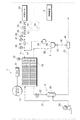
まず、図1を用いて、本発明の実施形態に係る燃料電池システム1の全体構成について説明する。本実施形態に係る燃料電池システム1は、図1に示すように、反応ガス(酸化ガス及び燃料ガス)の供給を受けて電力を発生する燃料電池10を備えるとともに、燃料電池10に酸化ガスとしての空気を供給する酸化ガス配管系2、燃料電池10に燃料ガスとしての水素ガスを供給する水素ガス配管系3、システム全体を統合制御する制御装置4等を備えている。
1. Overall Configuration of Fuel Cell System According to an Embodiment of the Present Invention First, an overall configuration of a fuel cell system 1 according to an embodiment of the present invention will be described with reference to FIG. As shown in FIG. 1, the fuel cell system 1 according to the present embodiment includes a
燃料電池10は、反応ガスの供給を受けて発電する単電池を所要数積層して構成したスタック構造を有している。燃料電池10により発生した電力は、PCU(Power Control Unit)11に供給される。PCU11は、燃料電池10とトラクションモータ12との間に配置されるインバータやDC‐DCコンバータ等を備えている。また、燃料電池10には、発電中の電流を検出する電流センサ13が取り付けられている。
The
酸化ガス配管系2は、加湿器20により加湿された酸化ガス(空気)を燃料電池10に供給する空気供給流路21と、燃料電池10から排出された酸化オフガスを加湿器20に導く空気排出流路22と、加湿器21から外部に酸化オフガスを導くための排気流路23と、を備えている。空気供給流路21には、大気中の酸化ガスを取り込んで加湿器20に圧送するコンプレッサ24が設けられている。
The oxidant
水素ガス配管系3は、高圧の水素ガスを貯留した燃料供給源としての水素タンク30と、水素タンク30の水素ガスを燃料電池10に供給するための燃料供給流路としての水素供給流路31と、燃料電池10から排出された水素オフガスを水素供給流路31に戻すための循環流路32と、を備えている。なお、水素タンク30に代えて、炭化水素系の燃料から水素リッチな改質ガスを生成する改質器と、この改質器で生成した改質ガスを高圧状態にして蓄圧する高圧ガスタンクと、を燃料供給源として採用することもできる。また、水素吸蔵合金を有するタンクを燃料供給源として採用してもよい。
The hydrogen gas piping system 3 includes a
水素供給流路31には、水素タンク30からの水素ガスの供給を遮断又は許容する遮断弁33と、水素ガスの圧力を調整するレギュレータ34と、インジェクタ35と、が設けられている。また、インジェクタ35の上流側には、水素供給流路31内の水素ガスの圧力及び温度を検出する一次側圧力センサ41及び温度センサ42が設けられている。また、インジェクタ35の下流側であって水素供給流路31と循環流路32との合流部A1の上流側には、水素供給流路31内の水素ガスの圧力を検出する二次側圧力センサ43が設けられている。
The hydrogen
レギュレータ34は、その上流側圧力(一次圧)を、予め設定した二次圧に調圧する装置である。本実施形態においては、一次圧を減圧する機械式の減圧弁をレギュレータ34として採用している。機械式の減圧弁の構成としては、背圧室と調圧室とがダイアフラムを隔てて形成された筺体を有し、背圧室内の背圧により調圧室内で一次圧を所定の圧力に減圧して二次圧とする公知の構成を採用することができる。本実施形態においては、図1に示すように、インジェクタ35の上流側にレギュレータ34を2個配置することにより、インジェクタ35の上流側圧力を効果的に低減させることができる。このため、インジェクタ35の機械的構造(弁体、筺体、流路、駆動装置等)の設計自由度を高めることができる。また、インジェクタ35の上流側圧力を低減させることができるので、インジェクタ35の上流側圧力と下流側圧力との差圧の増大に起因してインジェクタ35の弁体が移動し難くなることを抑制することができる。従って、インジェクタ35の下流側圧力の可変調圧幅を広げることができるとともに、インジェクタ35の応答性の低下を抑制することができる。
The
インジェクタ35は、弁体を電磁駆動力で直接的に所定の駆動周期で駆動して弁座から離隔させることによりガス流量やガス圧を調整することが可能な電磁駆動式の開閉弁である。インジェクタ35は、水素ガス等の気体燃料を噴射する噴射孔を有する弁座を備えるとともに、その気体燃料を噴射孔まで供給案内するノズルボディと、このノズルボディに対して軸線方向(気体流れ方向)に移動可能に収容保持され噴射孔を開閉する弁体と、を備えている。本実施形態においては、インジェクタ35の弁体は電磁駆動装置であるソレノイドにより駆動され、このソレノイドに給電されるパルス状励磁電流のオン・オフにより、噴射孔の開口面積を2段階又は多段階に切り替えることができるようになっている。制御装置4から出力される制御信号によってインジェクタ35のガス噴射時間及びガス噴射時期が制御されることにより、水素ガスの流量及び圧力が高精度に制御される。インジェクタ35は、弁(弁体及び弁座)を電磁駆動力で直接開閉駆動するものであり、その駆動周期が高応答の領域まで制御可能であるため、高い応答性を有する。
The
インジェクタ35は、その下流に要求されるガス流量を供給するために、インジェクタ35のガス流路に設けられた弁体の開口面積(開度)及び開放時間の少なくとも一方を変更することにより、下流側(燃料電池10側)に供給されるガス流量(又は水素モル濃度)を調整する。なお、インジェクタ35の弁体の開閉によりガス流量が調整されるとともに、インジェクタ35下流に供給されるガス圧力がインジェクタ35上流のガス圧力より減圧されるため、インジェクタ35を調圧弁(減圧弁、レギュレータ)と解釈することもできる。また、本実施形態では、ガス要求に応じて所定の圧力範囲の中で要求圧力に一致するようにインジェクタ35の上流ガス圧の調圧量(減圧量)を変化させることが可能な可変調圧弁と解釈することもできる。
なお、本実施形態においては、図1に示すように、水素供給流路31と循環流路32との合流部A1より上流側にインジェクタ35を配置している。また、図1に破線で示すように、燃料供給源として複数の水素タンク30を採用する場合には、各水素タンク30から供給される水素ガスが合流する部分(水素ガス合流部A2)よりも下流側にインジェクタ35を配置するようにする。
In the present embodiment, as shown in FIG. 1, the
循環流路32には、気液分離器36及び排気排水弁37を介して、排出流路38が接続されている。気液分離器36は、水素オフガスから水分を回収するものである。排気排水弁37は、制御装置4からの指令によって作動することにより、気液分離器36で回収した水分と、循環流路32内の不純物を含む水素オフガス(燃料オフガス)と、を外部に排出(パージ)するものである。また、循環流路32には、循環流路32内の水素オフガスを加圧して水素供給流路31側へ送り出す水素ポンプ39が設けられている。なお、排気排水弁37及び排出流路38を介して排出される水素オフガスは、希釈器40によって希釈されて排気流路23内の酸化オフガスと合流するようになっている。
A
制御装置4は、車両に設けられた加速操作部材(アクセル等)の操作量を検出し、加速要求値(例えばトラクションモータ12等の負荷装置からの要求発電量)等の制御情報を受けて、システム内の各種機器の動作を制御する。なお、負荷装置とは、トラクションモータ12のほかに、燃料電池10を作動させるために必要な補機装置(例えばコンプレッサ24、水素ポンプ39、冷却ポンプのモータ等)、車両の走行に関与する各種装置(変速機、車輪制御装置、操舵装置、懸架装置等)で使用されるアクチュエータ、乗員空間の空調装置(エアコン)、照明、オーディオ等を含む電力消費装置を総称したものである。
The
制御装置4は、図示していないコンピュータシステムによって構成されている。かかるコンピュータシステムは、CPU、ROM、RAM、HDD、入出力インタフェース及びディスプレイ等を備えるものであり、ROMに記録された各種制御プログラムをCPUが読み込んで実行することにより、各種制御動作が実現されるようになっている。
The
具体的には、制御装置4は、図2に示すように、燃料電池10の運転状態(電流センサ13で検出した燃料電池10の発電時の電流値)に基づいて、燃料電池10で消費される水素ガスの量(以下「水素消費量」という)を算出する(燃料消費量算出機能:B1)。本実施形態においては、燃料電池10の電流値と水素消費量との関係を表す特定の演算式を用いて、制御装置4の演算周期毎に水素消費量を算出して更新することとしている。
Specifically, as shown in FIG. 2, the
また、制御装置4は、燃料電池10の運転状態(電流センサ13で検出した燃料電池10の発電時の電流値)に基づいて、インジェクタ35下流位置における水素ガスの目標圧力値(燃料電池10への目標ガス供給圧)を算出する(目標圧力値算出機能:B2)。本実施形態においては、燃料電池10の電流値と目標圧力値との関係を表す特定のマップを用いて、制御装置4の演算周期毎に、二次側圧力センサ43が配置された位置における目標圧力値を算出して更新することとしている。
Further, the
また、制御装置4は、算出した目標圧力値と、二次側圧力センサ43で検出したインジェクタ35下流位置の圧力値(検出圧力値)と、の偏差に基づいてフィードバック補正流量を算出する(フィードバック補正流量算出機能:B3)。フィードバック補正流量は、目標圧力値と検出圧力値との偏差を低減させるために水素消費量に加算される水素ガス流量である。本実施形態においては、PI型フィードバック制御則を用いて、制御装置4の演算周期毎にフィードバック補正流量を算出して更新することとしている。
Further, the
また、制御装置4は、インジェクタ35の上流のガス状態(一次側圧力センサ41で検出した水素ガスの圧力及び温度センサ42で検出した水素ガスの温度)に基づいてインジェクタ35の上流の静的流量を算出する(静的流量算出機能:B4)。本実施形態においては、インジェクタ35の上流側の水素ガスの圧力及び温度と静的流量との関係を表す特定の演算式を用いて、制御装置4の演算周期毎に静的流量を算出して更新することとしている。
Further, the
また、制御装置4は、インジェクタ35の上流のガス状態(水素ガスの圧力及び温度)及び印加電圧に基づいてインジェクタ35の無効噴射時間を算出する(無効噴射時間算出機能:B5)。本実施形態においては、インジェクタ35の上流側の水素ガスの圧力及び温度と印加電圧と無効噴射時間との関係を表す特定のマップを用いて、制御装置4の演算周期毎に無効噴射時間を算出して更新することとしている。
Further, the
また、制御装置4は、水素消費量とフィードバック補正流量とを加算することにより、インジェクタ35の噴射流量を算出する(噴射流量算出機能:B6)。そして、制御装置4は、インジェクタ35の噴射流量を静的流量で除した値にインジェクタ35の駆動周期を乗じることにより、インジェクタ35の基本噴射時間を算出するとともに、この基本噴射時間と無効噴射時間とを加算してインジェクタ35の総噴射時間を算出する(総噴射時間算出機能:B7)。ここで、駆動周期とは、インジェクタ35の噴射孔の開閉状態を表す段状(オン・オフ)波形の周期を意味する。本実施形態においては、制御装置4により駆動周期を一定の値に設定している。
Further, the
そして、制御装置4は、以上の手順を経て算出したインジェクタ35の総噴射時間を実現させるための制御信号を送出することにより、インジェクタ35のガス噴射時間及びガス噴射時期を制御して、燃料電池10に供給される水素ガスの流量及び圧力を調整する。
Then, the
また、制御装置4は、システム始動時において、インジェクタ35上流側における水素ガスの圧力値が所定の閾値より大きい場合に、インジェクタ35に制御信号(例えば無効電流)を送出することにより、インジェクタ35の開閉制御を行う。本実施形態においては、この所定の閾値として、燃料電池10の最大出力の保証圧力(燃料電池10が最大出力で発電を行う際のインジェクタ35上流側における水素ガスの圧力値)を採用している。ここで、燃料電池の出力と燃料電池への水素ガスの供給量とは通常1対1で対応するから、本実施例においては、上記最大出力の保証圧力は、燃料電池10に供給される水素ガスの最大流量の保証圧力(燃料電池10に最大流量の水素ガスを供給する際のインジェクタ35上流側における水素ガスの圧力値)と一致する。
Further, the
2.本発明の実施の形態にかかる燃料電池システムの制御方法
次に、燃料電池システム1の制御方法について、特にシステム始動時の制御方法を中心に説明する。
2. Control Method of Fuel Cell System According to Embodiment of the Present Invention Next, the control method of the fuel cell system 1 will be described focusing on the control method at the time of starting the system.
燃料電池システム1の通常運転時においては、水素タンク30から水素ガスが水素供給流路31を介して燃料電池10の燃料極に供給されるとともに、加湿調整された空気が空気供給流路21を介して燃料電池10の酸化極に供給されることにより、発電が行われる。この際、燃料電池10から引き出すべき電力(要求電力)が制御装置4で演算され、その発電量に応じた量の水素ガス及び空気が燃料電池10内に供給されるようになっている。
During normal operation of the fuel cell system 1, hydrogen gas is supplied from the
本実施形態においては、上記通常運転を開始する際の燃料電池システムの始動方法に特に特徴がある。以下、図3乃至図5を用いて説明する。 The present embodiment is particularly characterized in the method for starting the fuel cell system when the normal operation is started. This will be described below with reference to FIGS.
図3は、燃料電池システムの始動時の制御方法を説明するためのフローチャートである。図3に示すように、はじめに、制御装置4は、運転停止状態において、運転開始信号(イグニッションスイッチのON信号)の有無を判定する(運転開始判定工程:S1)。運転開始信号を検出した場合、制御装置4は、遮断弁33及びレギュレータ34を開き、水素タンク3から水素供給流路31への水素の供給を開始する(水素供給工程:S2)。
FIG. 3 is a flowchart for explaining a control method at the start of the fuel cell system. As shown in FIG. 3, first, the
次いで、制御装置4は、一次側圧力センサ41を用いて、水素供給流路31のインジェクタ35上流側の水素ガスの圧力(一次圧)を検出し(一次圧検出工程:S3)、一次圧Pが所定の閾値P0より大きいかを判定する(一次圧判定工程:S4)。ここで、閾値P0は、上述したように本実施形態においては、燃料電池10の最大出力の保証圧力である。
Next, the
制御装置4は、一次圧判定工程S4において一次圧Pが所定の閾値P0より大きいと判定した場合には、インジェクタ35に制御信号(駆動指令)を送出してインジェクタ35の開閉制御を開始する(インジェクタ制御開始工程:S5)。制御装置4は、一次圧判定工程S4において一次圧Pが所定の閾値P0に達していないと判定した場合には、一定期間経過後、一次圧検出工程S4から工程を開始する。
When determining that the primary pressure P is greater than the predetermined threshold value P 0 in the primary pressure determination step S4, the
以上の工程を経ることにより次のような効果がある。以下、(1)水素タンクのガス圧力が低い場合(図4)と、(2)水素タンクのガス圧力が高い場合(図5)とに分け、従来例と比較しつつ説明する。ここでは、比較例として、水素が燃料供給源から燃料供給流路に供給されてから一定時間経過後(t2)インジェクタの制御を開始する従来技術を用いている。また、水素タンクのガス圧力が高い場合とは、例えば、水素タンクに十分な量のガスが充填されている場合であり、水素タンクのガス圧力が低い場合とは、例えば、水素タンクに充填されているガスの量が残り少ないような場合である。 Through the above steps, the following effects are obtained. Hereinafter, (1) the case where the gas pressure in the hydrogen tank is low (FIG. 4) and (2) the case where the gas pressure in the hydrogen tank is high (FIG. 5) will be described in comparison with the conventional example. Here, as a comparative example, a conventional technique is used in which the control of the injector is started after a lapse of a certain time after hydrogen is supplied from the fuel supply source to the fuel supply flow path (t 2 ). The case where the gas pressure in the hydrogen tank is high is, for example, a case where a sufficient amount of gas is filled in the hydrogen tank, and the case where the gas pressure in the hydrogen tank is low is, for example, that the hydrogen tank is filled. This is the case when the amount of gas remaining is low.
(1)水素タンクのガス圧力が低い場合
図4は、水素タンクのガス圧力が低い場合の燃料電池システム1の始動時の制御方法を説明するためのタイムチャートであり、(A)は水素タンクの遮断弁の制御信号(駆動指令)の時間履歴を示すもの、(B)は、インジェクタの一次圧の時間履歴を示すもの、(C)は、インジェクタの制御信号(駆動指令)の時間履歴を示すものである。図4においては、本実施形態に係る実施例の時間履歴を実線で示し、比較例にかかる時間履歴を破線で示した。
(1) When the gas pressure in the hydrogen tank is low FIG. 4 is a time chart for explaining a control method at the start of the fuel cell system 1 when the gas pressure in the hydrogen tank is low, and (A) is a hydrogen tank. Shows the time history of the control signal (drive command) of the shutoff valve, (B) shows the time history of the primary pressure of the injector, and (C) shows the time history of the control signal (drive command) of the injector. It is shown. In FIG. 4, the time history of the example according to the present embodiment is indicated by a solid line, and the time history according to the comparative example is indicated by a broken line.
比較例においては、図4(A)に示すように、運転開始信号の検出時(t0)に、水素タンク遮断弁の駆動指令がOFFからONに変わったのち、図4(C)に示すように、一定時間(t2)が経過すると、インジェクタ駆動指令がOFFからONに切り替わる。従って、図4(B)に示すようにインジェクタ一次圧Pが所定の閾値P0に達する前にインジェクタの制御が開始されてしまう。そのため、はじめから燃料電池が最大出力で発電を行う必要がある場合(例えば、燃料電池車両において発進時にアクセルを全開にした場合)は、燃料電池に供給される燃料ガスの量が不足することになる。これにより燃料ガスの供給量に見合わない過量の発電が行われ、電解質ひいては燃料電池の劣化を招いてしまう。 In the comparative example, as shown in FIG. 4A, when the operation start signal is detected (t 0 ), the drive command for the hydrogen tank shut-off valve is changed from OFF to ON, and then shown in FIG. 4C. Thus, when a certain time (t 2 ) elapses, the injector drive command is switched from OFF to ON. Therefore, as shown in FIG. 4B, the control of the injector is started before the injector primary pressure P reaches the predetermined threshold value P 0 . Therefore, when the fuel cell needs to generate power at the maximum output from the beginning (for example, when the accelerator is fully opened at the start of the fuel cell vehicle), the amount of fuel gas supplied to the fuel cell is insufficient. Become. As a result, an excessive amount of power generation that does not match the amount of fuel gas supplied is performed, leading to deterioration of the electrolyte and thus the fuel cell.
これに対し、本実施形態においては、図4(A)に示すように、運転開始信号の検出時(t0)に水素タンク遮断弁の駆動指令がOFFからONに変わると、図4(B)に示すように、インジェクタ一次圧が徐々に上昇し、この圧力が所定の閾値P0に達した時(t3)に、図4(C)に示すように、インジェクタの駆動指令がOFFからONに切り替わりインジェクタの制御が開始される。 On the other hand, in this embodiment, as shown in FIG. 4A, when the drive command for the hydrogen tank shut-off valve changes from OFF to ON at the time of detection of the operation start signal (t 0 ), FIG. ), When the injector primary pressure gradually increases and this pressure reaches a predetermined threshold value P 0 (t 3 ), as shown in FIG. It switches to ON and control of the injector is started.
従って、はじめから燃料電池10が最大出力で発電を行う必要がある場合であっても、一次圧Pが燃料電池10の最大出力の保証圧力(P0)に達しているので、燃料電池10に過不足なく水素を供給することができる。
Accordingly, even when the
(2)水素タンクのガス圧力が高い場合
図5は、水素タンクのガス圧力が高い場合の燃料電池システム1の始動時の制御方法を説明するためのタイムチャートであり、(A)は水素タンクの遮断弁の制御信号(駆動指令)の時間履歴を示すもの、(B)は、インジェクタの一次圧の時間履歴を示すもの、(C)は、インジェクタの制御信号(駆動指令)の時間履歴を示すものである。図5においても、本実施形態の実施例に係る時間履歴を実線で示し、比較例にかかる時間履歴を破線で示した。
(2) When the gas pressure in the hydrogen tank is high FIG. 5 is a time chart for explaining a control method at the start of the fuel cell system 1 when the gas pressure in the hydrogen tank is high, and (A) is a hydrogen tank. Shows the time history of the control signal (drive command) of the shutoff valve, (B) shows the time history of the primary pressure of the injector, and (C) shows the time history of the control signal (drive command) of the injector. It is shown. Also in FIG. 5, the time history according to the example of the present embodiment is indicated by a solid line, and the time history according to the comparative example is indicated by a broken line.
比較例においては、図5(A)に示すように、運転開始信号の検出時(t0)に、水素タンク遮断弁の駆動指令がOFFからONに変わると、図5(B)に示すように、水素タンクのガス圧力が低い場合に比べて、インジェクタの一次圧が比較的早く上昇するが、閾値P0を越えても、図4(C)に示すように、インジェクタ駆動指令は、一定時間(t2)が経過するまでなされない。 In the comparative example, as shown in FIG. 5 (A), when the drive command for the hydrogen tank shut-off valve changes from OFF to ON at the time of detection of the operation start signal (t 0 ), as shown in FIG. 5 (B). In addition, the primary pressure of the injector rises relatively quickly as compared with the case where the gas pressure in the hydrogen tank is low. However, even if the threshold P 0 is exceeded, the injector drive command is constant as shown in FIG. Not done until time (t 2 ) has elapsed.
これに対し、本実施の形態においては、図5(A)に示すように、運転開始信号の検出時(t0)に水素タンク遮断弁の駆動指令がOFFからONに変わったのち、図5(B)に示すように、インジェクタの一次圧が所定の閾値P0に達した時(t1)に、図4(C)に示すように、インジェクタの駆動指令がOFFからONに切り替わりインジェクタの制御が開始される。 On the other hand, in this embodiment, as shown in FIG. 5A, after the drive command for the hydrogen tank shut-off valve is changed from OFF to ON at the time of detecting the operation start signal (t 0 ), FIG. As shown in FIG. 4B, when the primary pressure of the injector reaches a predetermined threshold value P 0 (t 1 ), the injector drive command is switched from OFF to ON, as shown in FIG. 4C. Control begins.
従って、比較例のように一定期間経過を待つことなしに、燃料電池システム1の運転を開始することができ、システムの始動にかかる時間を短縮することができる。ここで、インジェクタの一次圧が燃料電池10の最大出力の保証圧力(P0)に達しているから、はじめから燃料電池10が最大出力で発電を行う必要がある場合であっても、燃料電池10に過不足なく水素を供給することができる。
Therefore, the operation of the fuel cell system 1 can be started without waiting for a certain period of time as in the comparative example, and the time required for starting the system can be shortened. Here, since the primary pressure of the injector reaches the guaranteed output pressure (P 0 ) of the maximum output of the
上記(1)、(2)で説明したように、本実施の形態にかかる燃料電池システム1は、燃料電池10への水素の供給量不足を防止し、かつ供給のタイミングを最適化することができる。
As described in the above (1) and (2), the fuel cell system 1 according to the present embodiment can prevent a shortage of hydrogen supply to the
3.本発明の実施の形態にかかる燃料電池システムの変形例
以上本発明の実施形態を示したが、本発明はこの実施の形態に限定されるものではなく、その要旨を逸脱しない範囲内において様々な態様での実施が可能である。例えば以下のような変形例が可能である。
3. Modification of Fuel Cell System According to Embodiment of Present Invention Although the embodiment of the present invention has been described above, the present invention is not limited to this embodiment, and various modifications can be made without departing from the scope of the present invention. Implementation in an embodiment is possible. For example, the following modifications are possible.
以上の実施形態では、「所定の閾値」として、燃料電池10の最大出力の保証圧力を採用しているが、これに限られるものではない。例えば、所定の閾値を、上記最大出力の保証圧力の前後数%以内に設定してもよいし、燃料電池10の耐久性等の機械的強度により定まる最大許容圧力としてもよい。また、例えば、燃料電池システムや燃料電池車両の状態を検知して、その状態に応じて変動させるようにしてもよい。
In the above embodiment, the guaranteed output pressure of the maximum output of the
また、以上の実施形態においては、燃料電池システム1の水素ガス配管系3に循環流路32を設けた例を示したが、例えば、図6に示すように、燃料電池10に排出流路38を直接接続して循環流路32を廃止することもできる。かかる構成(デッドエンド方式)を採用した場合においても、制御装置4で前記実施形態と同様にシステム始動においてインジェクタ35に制御信号を送出してインジェクタ35の開閉制御を行うことにより、同様の作用効果を得ることができる。
Moreover, in the above embodiment, although the example which provided the
また、以上の実施形態においては、本発明における開閉弁としてインジェクタ35を採用した例を示したが、開閉弁は供給流路(水素供給流路31)の上流側のガス状態を調整して下流側に供給するものであればよく、インジェクタ35に限られるものではない。
Moreover, in the above embodiment, although the example which employ | adopted the
また、以上の各実施形態においては、本発明に係る燃料電池システムを燃料電池車両に搭載した例を示したが、燃料電池車両以外の各種移動体(ロボット、船舶、航空機等)に本発明に係る燃料電池システムを搭載することもできる。また、本発明に係る燃料電池システムを、建物(住宅、ビル等)用の発電設備として用いられる定置用発電システムに適用してもよい。 Further, in each of the above embodiments, an example in which the fuel cell system according to the present invention is mounted on a fuel cell vehicle has been shown. Such a fuel cell system can also be mounted. Further, the fuel cell system according to the present invention may be applied to a stationary power generation system used as a power generation facility for a building (house, building, etc.).
1 ……燃料電池システム
10……燃料電池
11……PCU
12……トランクションモータ
13……電流センサ
2 ……酸化ガス配管系
20……加湿器
21……空気供給経路
22……空気排出経路
23……排気流路
24……コンプレッサ
3 ……水素ガス配管系(燃料供給流路)
30……水素タンク(燃料供給源)
31……水素供給流路
32……循環流路
33……遮断弁
34……レギュレータ
35……インジェクタ(開閉弁)
36……気液分離器
37……排気排水弁
38……排出流路
39……水素ポンプ
4……制御装置
40……希釈器
41……一次側圧力センサ(圧力センサ)
42……温度センサ
43……二次側圧力センサ
1 ……
12 ...
30 …… Hydrogen tank (fuel supply source)
31 …… Hydrogen
36 ... Gas-
42 ……
Claims (5)
前記燃料電池に燃料ガスを供給する燃料供給流路と、
前記燃料供給流路の上流側のガス状態を調整して下流側に供給する開閉弁と、
前記開閉弁の駆動を制御する制御装置と、
前記燃料供給流路の上流側のガス圧を測定する圧力センサと、を備え、
前記制御装置は、システム始動時において、前記圧力センサにより測定されたガス圧が所定の圧力を超えたことを検知したときに、前記開閉弁の制御を開始する燃料電池システム。 A fuel cell;
A fuel supply channel for supplying fuel gas to the fuel cell;
An on-off valve that adjusts the gas state on the upstream side of the fuel supply flow path and supplies it to the downstream side;
A control device for controlling the driving of the on-off valve;
A pressure sensor for measuring a gas pressure upstream of the fuel supply channel,
The control device is a fuel cell system which starts control of the on-off valve when detecting that the gas pressure measured by the pressure sensor exceeds a predetermined pressure at the time of starting the system.
Priority Applications (1)
| Application Number | Priority Date | Filing Date | Title |
|---|---|---|---|
| JP2007180788A JP2009021024A (en) | 2007-07-10 | 2007-07-10 | Fuel cell system and mobile unit |
Applications Claiming Priority (1)
| Application Number | Priority Date | Filing Date | Title |
|---|---|---|---|
| JP2007180788A JP2009021024A (en) | 2007-07-10 | 2007-07-10 | Fuel cell system and mobile unit |
Publications (1)
| Publication Number | Publication Date |
|---|---|
| JP2009021024A true JP2009021024A (en) | 2009-01-29 |
Family
ID=40360519
Family Applications (1)
| Application Number | Title | Priority Date | Filing Date |
|---|---|---|---|
| JP2007180788A Pending JP2009021024A (en) | 2007-07-10 | 2007-07-10 | Fuel cell system and mobile unit |
Country Status (1)
| Country | Link |
|---|---|
| JP (1) | JP2009021024A (en) |
Cited By (1)
| Publication number | Priority date | Publication date | Assignee | Title |
|---|---|---|---|---|
| CN107004887A (en) * | 2014-12-09 | 2017-08-01 | 祖迪雅克航空技术公司 | Automated spacecraft fuel cell system |
-
2007
- 2007-07-10 JP JP2007180788A patent/JP2009021024A/en active Pending
Cited By (1)
| Publication number | Priority date | Publication date | Assignee | Title |
|---|---|---|---|---|
| CN107004887A (en) * | 2014-12-09 | 2017-08-01 | 祖迪雅克航空技术公司 | Automated spacecraft fuel cell system |
Similar Documents
| Publication | Publication Date | Title |
|---|---|---|
| JP5120590B2 (en) | Fuel cell system and injector diagnostic method | |
| JP5041272B2 (en) | Fuel cell system and moving body | |
| JP4780390B2 (en) | Fuel cell system and moving body | |
| JP4883360B2 (en) | Fuel cell system | |
| JP4438854B2 (en) | Fuel cell system | |
| JP4359856B2 (en) | Fuel cell system and moving body | |
| JP5076472B2 (en) | Fuel cell system | |
| JP2007165183A (en) | Fuel cell system and mobile body | |
| JP4882972B2 (en) | Fuel cell system | |
| JP4780427B2 (en) | Fuel cell system and moving body | |
| JP4655082B2 (en) | Fuel cell system | |
| JP5224080B2 (en) | Fuel cell system and off-gas purge method | |
| JP2007317597A (en) | Fuel cell system and diagnostic method of closing valve | |
| JP2009021025A (en) | Fuel cell system and mobile unit | |
| JP5168821B2 (en) | Fuel cell system | |
| JP5057203B2 (en) | Fuel cell system and moving body | |
| JP4863052B2 (en) | Fuel cell system and moving body | |
| JP2007323873A (en) | Fuel cell system and its control method | |
| JP5234485B2 (en) | Fuel cell system | |
| JP2008218034A (en) | Fuel cell system and method of controlling the same | |
| JP2007165162A (en) | Fuel cell system and mobile body | |
| JP2008140642A (en) | Fuel cell system | |
| JP2008004320A (en) | Fuel cell system, and mobile unit | |
| JP4941641B2 (en) | Fuel cell system | |
| JP2009021024A (en) | Fuel cell system and mobile unit |