JP2009018232A - Mixing passage structure mixing method for fluid - Google Patents
Mixing passage structure mixing method for fluid Download PDFInfo
- Publication number
- JP2009018232A JP2009018232A JP2007181274A JP2007181274A JP2009018232A JP 2009018232 A JP2009018232 A JP 2009018232A JP 2007181274 A JP2007181274 A JP 2007181274A JP 2007181274 A JP2007181274 A JP 2007181274A JP 2009018232 A JP2009018232 A JP 2009018232A
- Authority
- JP
- Japan
- Prior art keywords
- channel
- fluid
- flow path
- diluted
- flow
- Prior art date
- Legal status (The legal status is an assumption and is not a legal conclusion. Google has not performed a legal analysis and makes no representation as to the accuracy of the status listed.)
- Granted
Links
Images


Classifications
-
- E—FIXED CONSTRUCTIONS
- E02—HYDRAULIC ENGINEERING; FOUNDATIONS; SOIL SHIFTING
- E02B—HYDRAULIC ENGINEERING
- E02B5/00—Artificial water canals, e.g. irrigation canals
-
- B—PERFORMING OPERATIONS; TRANSPORTING
- B01—PHYSICAL OR CHEMICAL PROCESSES OR APPARATUS IN GENERAL
- B01F—MIXING, e.g. DISSOLVING, EMULSIFYING OR DISPERSING
- B01F25/00—Flow mixers; Mixers for falling materials, e.g. solid particles
- B01F25/40—Static mixers
- B01F25/42—Static mixers in which the mixing is affected by moving the components jointly in changing directions, e.g. in tubes provided with baffles or obstructions
- B01F25/421—Static mixers in which the mixing is affected by moving the components jointly in changing directions, e.g. in tubes provided with baffles or obstructions by moving the components in a convoluted or labyrinthine path
- B01F25/423—Static mixers in which the mixing is affected by moving the components jointly in changing directions, e.g. in tubes provided with baffles or obstructions by moving the components in a convoluted or labyrinthine path by means of elements placed in the receptacle for moving or guiding the components
- B01F25/4232—Static mixers in which the mixing is affected by moving the components jointly in changing directions, e.g. in tubes provided with baffles or obstructions by moving the components in a convoluted or labyrinthine path by means of elements placed in the receptacle for moving or guiding the components using dams
-
- B—PERFORMING OPERATIONS; TRANSPORTING
- B01—PHYSICAL OR CHEMICAL PROCESSES OR APPARATUS IN GENERAL
- B01D—SEPARATION
- B01D2257/00—Components to be removed
- B01D2257/30—Sulfur compounds
-
- B—PERFORMING OPERATIONS; TRANSPORTING
- B01—PHYSICAL OR CHEMICAL PROCESSES OR APPARATUS IN GENERAL
- B01D—SEPARATION
- B01D53/00—Separation of gases or vapours; Recovering vapours of volatile solvents from gases; Chemical or biological purification of waste gases, e.g. engine exhaust gases, smoke, fumes, flue gases, aerosols
- B01D53/34—Chemical or biological purification of waste gases
- B01D53/74—General processes for purification of waste gases; Apparatus or devices specially adapted therefor
- B01D53/77—Liquid phase processes
-
- C—CHEMISTRY; METALLURGY
- C02—TREATMENT OF WATER, WASTE WATER, SEWAGE, OR SLUDGE
- C02F—TREATMENT OF WATER, WASTE WATER, SEWAGE, OR SLUDGE
- C02F2103/00—Nature of the water, waste water, sewage or sludge to be treated
- C02F2103/08—Seawater, e.g. for desalination
Landscapes
- Chemical & Material Sciences (AREA)
- Dispersion Chemistry (AREA)
- Chemical Kinetics & Catalysis (AREA)
- Engineering & Computer Science (AREA)
- General Engineering & Computer Science (AREA)
- Mechanical Engineering (AREA)
- Civil Engineering (AREA)
- Structural Engineering (AREA)
- Treating Waste Gases (AREA)
Abstract
Description
本発明は、たとえば海水脱硫装置の排海水と希釈海水とを効率よく混合する流体の混合流路構造及び混合方法に関するものである。 The present invention relates to a fluid mixing channel structure and a mixing method for efficiently mixing waste seawater and diluted seawater of a seawater desulfurization device, for example.
従来、脱硫搭から排出される排海水は、環境対策としてエアレーションを行ってから海域に放流することが行われている。しかしながら、海域に放流する直前においては、必要に応じて放流海水(排海水)の性状(pH、DO、CODなど)を調整するため、フレッシュな希釈海水を混合する場合がある。
このような放流海水及び希釈海水を混合する混合流路構造としては、放流海水を流す放流水路と、希釈海水を流す導水路または導水管とを合流させる水路混合方式が知られている。なお、脱硫搭の排海水を希釈して放流する場合には、通常取り扱う排海水が多量になることから、流路断面積の大きな放流水路に対し比較的流路断面積の小さな導水路または導水管を合流させる混合流路構造が採用されている。
Conventionally, wastewater discharged from a desulfurization tower is discharged into the sea area after aeration as an environmental measure. However, immediately before discharging into the sea area, fresh diluted seawater may be mixed in order to adjust the properties (pH, DO, COD, etc.) of the discharged seawater (drained seawater) as necessary.
As such a mixing channel structure for mixing the discharged seawater and the diluted seawater, a water channel mixing system is known in which a discharge water channel for flowing the discharged seawater and a water conduit or a water conduit for flowing the diluted seawater are merged. When diluting the discharged seawater from the desulfurization tower and discharging it, a large amount of discharged seawater is usually handled. A mixing channel structure that joins the water pipes is adopted.
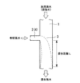
ここで、上述した水路混合方式による混合流路構造について、図19から図22に基づいて簡単に説明する。
図19及び図20に示す混合流路構造は、排海水を流す放流水路1と希釈海水を流す導水路2とが略同一水面WLで直交するようにしてT字状に合流している。そして、放流水路1には、図22に示すように、導水路2と合流する合流位置3から必要な混合距離Lが設けられている。この混合距離Lは、合流後の排海水及び希釈海水を流れにより混合し、性状が所定値以下の略均一濃度に希釈された混合海水とするのに必要な放流水路1の流路長さである。従って、放流水路1を流れる排海水は、混合距離Lの間で希釈海水と略均一に混合された混合海水となって海域に放流される。
Here, the mixing channel structure by the water channel mixing method described above will be briefly described with reference to FIGS. 19 to 22.
In the mixed flow channel structure shown in FIGS. 19 and 20, the discharge water channel 1 through which the waste seawater flows and the water conduit 2 through which the diluted sea water flows are joined in a T shape so as to be orthogonal to each other on substantially the same water surface WL. And in the discharge water channel 1, the required mixing distance L is provided from the confluence | merging
また、図21に示す混合流路構造は、導水路2に代えて導水管4を採用している。この導水管4は、放流水路1を流れる排海水の水面より低い位置でT字状に合流しており、合流位置5の下流に設けた混合距離Lの間で希釈海水と略均一に混合された混合海水となって海域に放流される。
なお、脱硫搭から排出される排海水を海域に放水する際、希釈海水を混合して略均一に希釈された混合海水とするために必要な混合距離Lを短縮可能な混合流路構造に関する技術文献は見当たらない。
21 employs a
In addition, when discharging the discharged seawater discharged from the desulfurization tower into the sea area, a technology relating to a mixing channel structure capable of shortening the mixing distance L necessary for mixing the diluted seawater to obtain the mixed seawater diluted substantially uniformly. There is no literature.
しかしながら、上述した従来の水路混合方式による混合流路構造は、放流水路1に水路側面から希釈海水を流入させて混合するため、略均一な混合海水とする混合完了までには長い混合距離Lが必要となる。これは、排海水の流れに対して側面から希釈海水を合流させるため、放流水路1内の希釈海水は排海水の流れから大きな影響を受けることとなり、従って、希釈海水は、放流水路1の流路幅方向において、流入した側壁の反対側まで容易に到達(横断)できないためと考えられる。 However, since the mixing channel structure based on the conventional water channel mixing method described above flows into the discharge water channel 1 from the side surface of the water channel and mixes the diluted sea water, a long mixing distance L is required until the mixing to obtain a substantially uniform mixed sea water. Necessary. This is because the diluted seawater is merged from the side with respect to the flow of the discharged seawater, so that the diluted seawater in the discharge channel 1 is greatly affected by the flow of the discharged seawater. This is considered to be because it is not possible to easily reach (cross) the side opposite to the inflow side wall in the road width direction.
そして、上述した混合距離Lの長い放流水路1を設置するには、大きな敷地とともに多額の建設費が必要となる。このため、脱硫搭から排出される排海水を海域に放流する際、所定の環境基準を満たす混合海水に希釈して放流するには、用地確保や建設費増大などの問題が大きな障害となっている。なお、上述した混合距離Lは、排海水及び希釈海水の流量や水路形状等の諸条件に応じて異なってくる。
本発明は、上記の事情に鑑みてなされたものであり、その目的とするところは、二流体の混合に必要となる混合距離Lを低減し、効率のよい混合が可能となる流体の混合流路構造及び混合方法を提供することにある。
And in order to install the discharge channel 1 with the long mixing distance L described above, a large construction cost is required together with a large site. For this reason, when discharging the discharged seawater discharged from the desulfurization tower to the sea area, problems such as securing land and increasing construction costs become a major obstacle to diluting and discharging to the mixed seawater that satisfies the predetermined environmental standards. Yes. In addition, the mixing distance L mentioned above changes according to various conditions, such as the flow volume and water channel shape of wastewater and diluted seawater.
The present invention has been made in view of the above circumstances, and the object of the present invention is to reduce the mixing distance L required for mixing two fluids and to mix the fluids efficiently. It is to provide a path structure and a mixing method.
本発明は、上記の課題を解決するため、下記の手段を採用した。
本発明に係る流体の混合流路構造は、第1流路を流れる被希釈流体に第2流路を流れる希釈流体を合流させて希釈した混合流体を放流する流体の混合流路構造において、前記第1流路を流れる被希釈流体の水中に流路側面から前記第2流路を合流させるとともに、前記第2流路と前記第1流路との合流部水中に堰を設け、前記被希釈流体が流路流れ方向に流れる底面部の流れを規制したことを特徴とするものである。
In order to solve the above problems, the present invention employs the following means.
The fluid mixing channel structure according to the present invention is the fluid mixing channel structure for discharging the diluted fluid by joining the diluted fluid flowing through the first channel to the diluted fluid flowing through the second channel, The second flow path is joined from the side of the flow path into the water to be diluted flowing in the first flow path, and a weir is provided in the merged water of the second flow path and the first flow path. The present invention is characterized in that the flow of the bottom surface portion in which the fluid flows in the flow path flow direction is regulated.
このような流体の混合流路構造によれば、第1流路を流れる被希釈流体の水中に流路側面から第2流路を合流させるとともに、第2流路と第1流路との合流部水中に堰を設け、被希釈流体が流路流れ方向に流れる底面部の流れを規制したので、流路側面から合流した希釈流体が被希釈流体の流れから受ける影響を低減することができ、第1流路内に流入した希釈流体を流路幅方向の反対側側壁まで容易に到達させることができる。
この場合、第2流路と第1流路との合流部水中に設けられる堰は、少なくとも第2流路の流路幅より下流側の近傍位置に設けられていればよいが、第2流路の流路幅より上流側及び下流側となる近傍位置の両方に設けられていることが好ましい。また、この場合の堰は、第2流路を流れる希釈流体が合流する位置と比較して、同じか高い位置まで設けられていることが望ましい。なお、希釈流体を被希釈流体の水中に流路側面から合流させる手段としては、いわゆる潜り堰や導水管を採用すればよい。
According to such a fluid mixing channel structure, the second channel is joined from the side surface of the fluid to be diluted flowing in the first channel from the side of the channel, and the second channel and the first channel are joined. Since weirs are provided in the submerged water and the flow of the bottom surface portion where the fluid to be diluted flows in the flow direction of the flow path is regulated, it is possible to reduce the influence of the diluted fluid merged from the flow path side surface from the flow of the fluid to be diluted. The diluted fluid that has flowed into the first channel can easily reach the opposite side wall in the channel width direction.
In this case, the weir provided in the joining portion water of the second flow path and the first flow path may be provided at least in the vicinity of the downstream side of the flow path width of the second flow path. It is preferable to be provided at both the upstream position and the downstream position from the flow path width of the path. In addition, it is desirable that the weir in this case is provided up to a position that is the same as or higher than the position where the diluted fluid flowing through the second flow path joins. In addition, what is necessary is just to employ | adopt what is called a diving dam and a water conduit as a means to join the dilution fluid to the water of a to-be-diluted fluid from a flow path side surface.
本発明に係る流体の混合流路構造は、第1流路を流れる被希釈流体に第2流路を流れる希釈流体を合流させて希釈した混合流体を放流する流体の混合流路構造において、前記第1流路を流れる被希釈流体の水中に流路側面から前記第2流路を合流させるとともに、前記第2流路を合流させた前記第1流路の合流部には、前記第2流路の流路幅より上流側及び下流側となる水中位置に、前記第2流路の流路高さ以上に高い堰が流路幅に設けられていることを特徴とするものである。 The fluid mixing channel structure according to the present invention is the fluid mixing channel structure for discharging the diluted fluid by joining the diluted fluid flowing through the first channel to the diluted fluid flowing through the second channel, The second flow path is joined from the side of the flow path into the fluid to be diluted flowing in the first flow path, and the second flow is formed at the merge portion of the first flow path where the second flow path is merged. A weir higher than the channel height of the second channel is provided in the channel width at an underwater position on the upstream side and downstream side of the channel width of the channel.
このような流体の混合流路構造によれば、第1流路を流れる被希釈流体の水中に流路側面から第2流路を合流させるとともに、第2流路を合流させた第1流路の合流部には、第2流路の流路幅より上流側及び下流側となる水中位置に、第2流路の流路高さ以上に高い堰が流路幅に設けられているので、第1流路の流路側面から被希釈流体の水中に合流した希釈流体は、被希釈流体の流れから受ける影響が低減され、第1流路内に流入した希釈流体を流路幅方向の反対側側壁まで容易に到達させることができる。なお、希釈流体を被希釈流体の水中に流路側面から合流させる手段としては、いわゆる潜り堰や導水管を採用すればよい。 According to such a fluid mixing channel structure, the first channel is formed by merging the second channel from the side surface of the diluted fluid flowing through the first channel and the second channel. Since the weir higher than the channel height of the second channel is provided in the channel width at the underwater position on the upstream side and downstream side of the channel width of the second channel, The dilution fluid that merges into the diluted fluid water from the flow channel side surface of the first flow channel is less affected by the flow of the diluted fluid, and the diluted fluid that flows into the first flow channel is opposite to the flow channel width direction. The side wall can be easily reached. In addition, what is necessary is just to employ | adopt what is called a diving dam and a water conduit as a means to join the dilution fluid to the water of a to-be-diluted fluid from a flow path side surface.
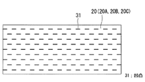
上述した流体の混合流路構造において、前記下流側の堰の上端部には、流路流れ方向に延在する平面部が形成されていることが好ましく、これにより、水深が浅くなって流路断面積を狭められた領域を形成することができる。この領域においては、合流した被希釈流体及び希釈流体が合流して流速を増すので、両流体の混合拡散が促進される。なお、この場合の平面部は、堰の下流側のみ、上流側のみ、または、下流側及び上流側のいずれでもよい。
このような平面部の水流表面に凹凸が形成されていることが好ましく、これにより、凹凸により流れが乱れてより一層混合が促進される。
In the fluid mixing channel structure described above, it is preferable that a flat portion extending in the channel flow direction is formed at the upper end portion of the downstream weir, whereby the water depth becomes shallower and the channel A region with a reduced cross-sectional area can be formed. In this region, the combined fluid to be diluted and the diluted fluid join together to increase the flow velocity, so that the mixed diffusion of both fluids is promoted. In addition, the plane part in this case may be only the downstream side of the weir, only the upstream side, or any of the downstream side and the upstream side.
It is preferable that unevenness is formed on the surface of the water flow in such a flat portion, whereby the flow is disturbed by the unevenness and the mixing is further promoted.
上述した流体の混合流路構造において、前記第2流路の流路幅より上流側に配置された堰は、前記第1流路の流路幅方向において、前記第2流路を合流させた流路壁側始点から対向する流路壁側終点へ向けて前記被希釈流体の流れ方向下流側へ傾斜していることが好ましく、これにより、第1流路の流路幅方向において、希釈流体が均一に分布して被希釈流体に混合される。 In the fluid mixing channel structure described above, the weir arranged upstream of the channel width of the second channel merges the second channel in the channel width direction of the first channel. It is preferable to incline toward the downstream side in the flow direction of the fluid to be diluted from the flow channel wall side start point to the opposite flow channel wall side end point. Are uniformly distributed and mixed with the fluid to be diluted.
本発明に係る流体の混合方法は、第1流路を流れる被希釈流体に第2流路を流れる希釈流体を流路側面から合流させて希釈した混合流体を放流する流体の混合方法において、前記希釈流体を前記被希釈流体の水中に合流させるとともに、前記希釈流体と前記被希釈流体との合流部で、前記被希釈流体が前記第1流路の流れ方向に沿って流れる流路底面部側の流れを規制したことを特徴とするものである。 The fluid mixing method according to the present invention is a fluid mixing method in which the diluted fluid flowing in the second flow path is joined to the diluted fluid flowing in the first flow path from the side surface of the flow path to release the diluted mixed fluid. The diluting fluid is merged into the diluted fluid water, and the flow path bottom surface side where the diluted fluid flows along the flow direction of the first flow path at the merged portion of the diluted fluid and the diluted fluid It is characterized by regulating the flow of
このような流体の混合方法によれば、第1流路を流れる被希釈流体に第2流路を流れる希釈流体を流路側面から合流させて希釈した混合流体を放流する流体の混合方法において、希釈流体を被希釈流体の水中に合流させるとともに、希釈流体と被希釈流体との合流部で、被希釈流体が第1流路の流れ方向に沿って流れる流路底面部側の流れを規制するようにしたので、流路側面から合流した希釈流体が被希釈流体の流れから受ける影響を低減することができ、第1流路内に流入した希釈流体は、流路幅方向の反対側側壁まで容易に到達することができる。 According to such a fluid mixing method, in the fluid mixing method in which the diluted fluid flowing in the second flow path is joined to the diluted fluid flowing in the first flow path from the side surface of the flow path and the diluted mixed fluid is discharged. The diluting fluid is merged in the water of the diluting fluid, and the flow on the flow path bottom surface side where the diluting fluid flows along the flow direction of the first flow path is regulated at the merging portion of the diluting fluid and the diluting fluid. Since it did in this way, the influence which the dilution fluid which merged from the flow-path side receives from the flow of a to-be-diluted fluid can be reduced, and the dilution fluid which flowed in in the 1st flow path is to the opposite side wall of a flow-path width direction. Can be reached easily.
上述した本発明によれば、たとえば脱硫塔から排出された排海水と希釈海水とを混合した混合海水を海域に放流する場合のように、二流体の混合に必要となる混合距離Lを低減し、効率のよい混合が可能となる流体の混合流路構造及び混合方法を提供することができる。従って、混合距離Lの短縮を可能にした本発明の混合流路及び混合方法は、流体混合用の流路構造を含むプラント建設に必要な敷地や建設費を低減でき、設計の自由度を増すという顕著な効果が得られる。 According to the present invention described above, the mixing distance L required for mixing the two fluids is reduced, for example, when the mixed seawater mixed with the wastewater discharged from the desulfurization tower and the diluted seawater is discharged into the sea area. Thus, it is possible to provide a fluid mixing channel structure and a mixing method that enable efficient mixing. Therefore, the mixing channel and the mixing method of the present invention that enable the mixing distance L to be shortened can reduce the site and construction cost required for plant construction including the channel structure for fluid mixing, and increase the degree of design freedom. The remarkable effect is obtained.
以下、本発明に係る流体の混合流路構造及び混合方法の一実施形態を図面に基づいて説明する。
<第1の実施形態>
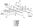
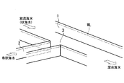
図1から図3に示す混合流路10は、たとえば排煙脱硫装置の脱硫塔から排出される多量の放流海水(排海水)にフレッシュな希釈海水を混合することにより、排海水の性状が環境基準等を満たすように希釈された混合海水として海域へ放流する場合に使用される。すなわち、図示の混合流路10は、排海水(被希釈流体)を流す放流水路(第1流路)11と、希釈海水(希釈流体)を流す導水路(第2流路)12とを備えており、二つの水路11,12は、一方の導水路12が他方の放流水路11と直交するようにして、一方の流路側面11aへT字状に合流している。換言すれば、混合流路10は、多量の排海水を流すため流路断面積が大きい放流水路11の流路側面11aに対し、比較的少量の希釈海水を流すため流路断面積も小さくなる導水路12がT字状に合流した構成とされる。
なお、この実施形態における放流水路11及び導水路12は、いずれも流路断面形状が矩形のオープン水路であり、排海水及び希釈海水の水面WLは同一高さになっている。
Hereinafter, an embodiment of a fluid mixing channel structure and a mixing method according to the present invention will be described with reference to the drawings.
<First Embodiment>
The
Note that the
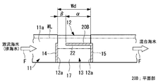
放流水路11と導水路12とが合流する合流位置13には、排海水が放流水路11の流路流れ方向(図中の白抜矢印F)に流れる底面部の流れを規制するため、排海水の流れ方向上流側から順に、第1堰14及び第2堰15が合流部水中に設けられている。
この場合の第1堰14及び第2堰15は、導水路12の流路幅Wdと略一致する間隔で平行に配置され、放流水路11の流路幅Whを横断して排海水の流れ方向と直交するように設置されている。すなわち、第1堰14及び第2堰15は、導水路12を形成する左右一対の側壁12aを延長した位置で対向するようにして水路底面11bから略垂直に立設され、放流水路11の水路底面11bから高さHまでの底面部流れを規制する壁面を形成したものである。
At the
In this case, the
上述した第1堰14及び第2堰15は、水圧に充分耐える強度を有する壁面が形成されていればよく、従って、本実施形態においては、たとえば比較的薄いコンクリート製の壁面等が採用される。しかし、第1堰14及び第2堰15は、コンクリート製限定されることはなく、たとえば鉄鋼構造体や鋼板などを採用してもよい。
The
一方、導水路12には、放流水路11内の排海水に対して、すなわち、放流水路11内を流れる排海水の水中に流路側面11aから希釈海水を合流させるため、導水路12の出口12bに第3堰16が設けられている。この第3堰16は、一般的には潜り堰と呼ばれており、導水路12の上部流れを規制するとともに、底面部側を開口して希釈海水の流路を形成している。この場合の第3堰16は、流路底面から高さhまでの範囲が開口して希釈海水の流路を形成するように設置された潜り堰であり、従って、流路底面11bからの高さhが水面WLより低い位置に設定されている。なお、図中の白抜矢印fは、希釈海水の流れ方向を示している。
On the other hand, the
また、第3堰16により形成された希釈海水の流路高さhは、上述した第1堰14及び第2堰15の高さHと同じか低くなる(h≦H)ように設定されている。従って、第1堰14及び第2堰15の高さHが水面WLより低いため、導水路12から高さhの開口部を通って合流する希釈海水は、必ず排海水の水中に合流することとなる。
Further, the flow path height h of the diluted seawater formed by the
このように、上述した混合流路10は、放水流路11を流れる排海水の水中に向けて、放流水路11の流路側面11aに開口する出口開口が高さhに規制されている導水路12から希釈海水を合流させるとともに、この希釈海水を合流させた放水流路11の合流部13に、排海水の底面部流れを高さHまで規制するようにした第1堰14及び第2堰15を備えているので、放水流路11に合流した希釈海水は、第1堰14及び第2堰15の間に形成されている横断流路17を通ることにより、排海水の流れによる影響が低減された状態で、流路幅Whの放水流路11を横切って反対側の側壁11cへ流れる。
すなわち、高さHの第1堰14及び第2堰15により形成された横断流路17が流路幅Whにわたって設けられているので、第3堰16によって出口開口の高さがhに制限された導水路12から排海水の流れ(水中)に合流した希釈海水は、その主流が第1堰14及び第2堰15により流れを規制された横断流路17を通って反対側の流路側面(側壁)11cまで容易に到達することができる。
In this way, the above-described
That is, since the
そして、横断流路17を流れる希釈海水は、第1堰14及び第2堰15により流路底面11b側の流れを規制されるため、流路断面積が減少することにより流速を増した状態で上方を流れる排海水に対し、流路幅Whの方向へ流れる際に上方へ溢れるように順次合流するので、流れに乱れが生じて効率よく混合される。このため、放水流路11の流路幅Wh方向においては、放水流路11を流れる排海水に対して希釈海水が略均一に合流して混合されるので、排海水と希釈海水とが合流して流れ全体が略均一の性状となるまでに必要な混合距離Lを短縮することが可能になる。
And since the dilution seawater which flows through the
ところで、上述した第1堰14及び第2堰15の高さHと出口開口の高さhとの関係については、希釈海水が横断流路17の高さHより低い水中に合流することにより、すなわち、出口開口の高さhが堰の高さHより低く設定されているほど排海水の流れから影響を受けにくくなるため好ましい。しかし、希釈海水の合流する高さhが横断流路17の高さHより高くなる場合であっても、多少混合距離Lは延びることにはなるが、第1堰14及び第2堰15により形成された横断流路17があれば、排海水の底面部で流れを規制できるため、横断流路17が全くない場合よりも混合距離Lを低減することは可能である。
By the way, regarding the relationship between the height H of the
<第2の実施形態>
次に、本発明に係る流体の混合流路構造について、第2の実施形態を図4及び図5に基づいて説明する。なお、上述した実施形態と同様の部分には同じ符号を付し、その詳細な説明は省略する。
さて、上述した実施形態では、第1堰14及び第2堰15を比較的薄いコンクリート製の壁面としたが、この実施形態の混合流路10Aには、排海水の流れ方向下流側に設置する堰として、上端部に流路流れ方向Fへ延在する平面部20が形成された第2堰15Aを採用している。すなわち、第2堰15Aは、排海水の流れ方向において、強度上必要となる幅(厚さ)と比較して充分に大きな長さαを有する平面部20が形成された柱状部材とされる。なお、この場合の第2堰15Aには、たとえばコンクリート製や鉄鋼構造体などを採用することができる。
<Second Embodiment>
Next, a second embodiment of the fluid mixing channel structure according to the present invention will be described with reference to FIGS. In addition, the same code | symbol is attached | subjected to the part similar to embodiment mentioned above, and the detailed description is abbreviate | omitted.
In the embodiment described above, the
このような第2堰15Aを採用すると、横断流路17の下流側には流路断面積の狭い放流水路11が平面部20の長さαにわたって形成されている。このため、平面部20を流れる混合海水は、排海水に加えて横断流路17から合流した希釈海水の分だけ流量を増すので、その流速がさらに増すとともに流れの乱れも増大することとなる。従って、平面部20の領域では、放流水路11を流れてきた排海水と横断流路17から合流した希釈海水とが混合拡散されるため効率よく確実に混合され、より一層短い混合距離Lでも流れ全体を略均一な性状とすることができる。
When such a
続いて、上述した平面部20の変形例を図6から図8に示して説明する。なお、上述した実施形態と同様の部分には同じ符号を付し、その詳細な説明は省略する。
図6に示す第1変形例の平面部20Aは、第1の実施形態に示した第2堰15の上端に取り付けた板状部材21の上端面により形成されている。この場合の板状部材21は、第2堰15の上端から流路流れ方向Fの下流側へ向けてL字状に取り付けられているので、上述した第2の実施形態の第2堰15Aと実質的に同様の作用効果もが得られる。すなわち、第2の実施形態に示した柱状の第2堰15Aから、流れに寄与しない面を形成する部分を取り除いたものとなる。
Subsequently, modified examples of the above-described
6A of the 1st modification shown in FIG. 6 is formed of the upper end surface of the plate-shaped
図7に示す第2変形例の平面部20Bは、下流側に取り付けた第1変形例の板状部材21とは異なり、第2堰15の上端から上流側へ向けて取り付けた板状部材22の上端面により形成されている。このような構成とすれば、横断流路17から排海水に合流する流路幅がβまで狭められるため、排海水に合流する希釈海水が放流水路11の流路幅Wh方向により一層均一化される。なお、上述した第2の実施形態及び第1変形例と同様に、平面部20Bの領域では、放流水路11を流れてきた排海水と横断流路17から合流した希釈海水とが混合拡散されるため効率よく確実に混合され、より一層短い混合距離Lでも流れ全体を略均一な性状とすることができる。
7 differs from the
図8に示す第3変形例の平面部20Cは、上述した第1変形例及び第2変形例を組み合わせたものであり、下流側に取り付けた板状部材21及び上流側に取り付けた板状部材22の上端面により形成されている。なお、この場合の板状部材21,22は、別体または一体のいずれでもよい。
このような構成とすれば、横断流路17から排海水に合流する流路幅がβまで狭められるため、排海水に合流する希釈海水が放流水路11の流路幅Wh方向により一層均一化され、さらに、平面部20Cの領域では、放流水路11を流れてきた排海水と横断流路17から合流した希釈海水とが混合拡散されるため効率よく確実に混合され、より一層短い混合距離Lでも流れ全体を略均一な性状とすることができる。
The
With such a configuration, the flow path width that merges with the drained seawater from the
<第3の実施形態>
次に、本発明に係る流体の混合流路構造について、第3の実施形態を図9に基づいて説明する。なお、上述した実施形態と同様の部分には同じ符号を付し、その詳細な説明は省略する。
さて、上述した実施形態では、第1堰14及び第2堰15を平行に配置したが、この実施形態の混合水路10Bでは、放流水路11の流路流れ方向Fにおいて上流側に配置された第1堰14Aが傾斜している。具体的に説明すると、導水路12の流路幅Wdより上流側に配置された第1堰14Aが、放流水路11の流路幅Wh方向において、導水路12を合流させた流路壁側始点Sから対向する流路壁側終点Eへ向けて、排海水の流れ方向下流側へ傾斜している。
<Third Embodiment>
Next, a third embodiment of the fluid mixing channel structure according to the present invention will be described with reference to FIG. In addition, the same code | symbol is attached | subjected to the part similar to embodiment mentioned above, and the detailed description is abbreviate | omitted.
In the embodiment described above, the
すなわち、第1堰14Aは、導水路12を合流させた流路側面11aに連結されている流路壁側始点Sが流路側面11cに連結されている流路壁側終点Eより上流側となるように傾斜しているので、合流位置13Aに形成された横断流路17Aの流路断面積は、導水路12の合流側側壁面から離間するにつれて徐々に減少することとなる。
このような横断流路17Aを形成することにより、横断流路17Aを流れる希釈海水の分布は流路幅Whの方向に均一化することとなる。換言すれば、横断流路17Aの平面視流路幅Wfは、流路途中で排海水に合流して流量が減少する流路終点E側へ近づくほど狭められているので、横断流路17内を流れる希釈海水の高さ(深さ)は流路幅Whの方向に均一化する。このため、横断流路17Aから排海水に合流する希釈海水量が流路幅Whの方向に均一化するので、混合距離Lを短縮しても効率よく混合されて流れ全体を略均一な性状とすることができる。なお、図示は省略したが、第2堰15については、上述した第2の実施形態及びその変形例を組み合わせた構成としてもよい。
That is, the first weir 14A has a flow path wall side start point S connected to the flow
By forming such a
<第4の実施形態>
次に、本発明に係る流体の混合流路構造について、第4の実施形態を図10に基づいて説明する。なお、上述した実施形態と同様の部分には同じ符号を付し、その詳細な説明は省略する。
この実施形態の混合流路10Cは、第1堰14を廃止して第2堰15のみが設置されている。すなわち、放流水路11を流れる排海水の底面部の流れは、第2堰15によって規制されている。このような構成は、堰が少なくてすむ分だけ建設コストを低減でき、しかも、混合距離Lの短縮も可能である。なお、図示は省略したが、第2堰15については、上述した第2の実施形態及びその変形例を組み合わせた構成としてもよい。
<Fourth Embodiment>
Next, a fourth embodiment of the fluid mixing channel structure according to the present invention will be described with reference to FIG. In addition, the same code | symbol is attached | subjected to the part similar to embodiment mentioned above, and the detailed description is abbreviate | omitted.
In the mixing
<第5の実施形態>
次に、本発明に係る流体の混合流路構造について、第5の実施形態を図11及び図12に基づいて説明する。なお、上述した実施形態と同様の部分には同じ符号を付し、その詳細な説明は省略する。
この実施形態の混合流路10Dは、上述した第1の実施形態の導水路12に代えて、導水管12Aを採用したものである。すなわち、オープン水路の導水路12から、配管による導水管12Aに変更したものである。
<Fifth Embodiment>
Next, a fifth embodiment of the fluid mixing channel structure according to the present invention will be described with reference to FIGS. In addition, the same code | symbol is attached | subjected to the part similar to embodiment mentioned above, and the detailed description is abbreviate | omitted.
The mixing
このような構成とすれば、放流水路11と、放流水路11の側面に合流する導水管12Aとの位置関係により、第3堰16のような潜り堰を設けなくても、排海水の水中に希釈海水を容易に合流させることができる。すなわち、少流量の希釈海水を流す導水管12Aは比較的小径の管を使用できるため、下端部を放流水路11の底面11bと略同じ位置に設定するとともに、導水管12Aの上端部が排海水の水面WLより低くなるようにして、放流水路11の流路側面11aに連結して合流させればよい。
なお、第1堰14及第2堰15により形成される横断流路17の作用効果については、上述した導水路12の場合と同様である。
With such a configuration, due to the positional relationship between the
In addition, about the effect of the
また、導水管12Aが開口する高さhと、第1堰14及び第2堰15の高さHとの関係については、良好な混合効率を得るためには上述した実施形態と同様に設定(h≦H)することが好ましい。
なお、上述した導水管12Aを用いた混合流路は、図示は省略したものの、上述した各実施形態との組み合わせが可能であり、それぞれ同様の作用効果を得ることができる。
In addition, the relationship between the height h at which the
In addition, although illustration was abbreviate | omitted, the mixing flow path using the
<第6の実施形態>
次に、本発明に係る流体の混合流路構造について、第6の実施形態を図13及び図14に基づいて説明する。なお、上述した実施形態と同様の部分には同じ符号を付し、その詳細な説明は省略する。
この実施形態では、上述した平面部20の水流表面に凹凸30を形成したものである。図13及び図14に示す凹凸30は、排海水や混合海水の流れと略直角に交差するようにして、流れと接する水流表面から直線状の薄板を等ピッチで複数凸設したものである。
<Sixth Embodiment>
Next, a sixth embodiment of the fluid mixing channel structure according to the present invention will be described with reference to FIGS. In addition, the same code | symbol is attached | subjected to the part similar to embodiment mentioned above, and the detailed description is abbreviate | omitted.
In this embodiment, the unevenness |
このような凹凸30が形成された平面部20は、排海水や混合海水の流れに渦を生じるなどして流れに乱れが生じるので、排海水と希釈海水との混合がより一層促進される。従って、平面部30に凹凸30を設けることは、混合距離Lの短縮に有効である。なお、このような凹凸30は、平面部20の変形例として説明した平面部20A,20B,20Cに設けた場合も同様の作用効果が得られるのは勿論であり、さらに、比較的厚さが薄いコンクリート製の第1堰14及び第2堰15についても、上端面に形成すれば流れを乱して混合効率を向上させることができる。
The
ところで、上述した凹凸30については種々の変形例が可能であり、その一部を図15から図17に示して説明する。
図15に示す第1変形例では、直線上で断続的に配置された凹凸31が流れ方向へ所定のピッチで複数列設けられている。この場合の凹凸31は、各々が薄板を突設したものであり、各凹凸31は千鳥状に配置されている。
By the way, various modifications can be made to the above-described
In the first modification shown in FIG. 15, a plurality of rows of
図16及び図17に示す第2変形例では、ジグザクの折れ線状とした凹凸32が流れ方向へ所定のピッチで複数列設けられている。この場合の凹凸32は、図17に示す断面図のように、たとえば薄板を折曲して平面20の表面に固着したものである。また、このような凹凸32に代えて、たとえば図18(a),(b)に示す第3変形例のように、薄板を鱗状に折曲した凹凸33A,33Bを平面20の表面に固着してもよい。
このような第1変形例1から第3変形例に示す凹凸31,32,33A,33Bを採用しても、排海水や混合海水の流れに渦を生じるなどして流れに乱れが生じるので、排海水と希釈海水との混合がより一層促進される。
In the second modified example shown in FIGS. 16 and 17, a plurality of rows of
Even if
上述した各実施形態の混合流路構造は、放流水路11を流れる排海水に導水路12または導水管12Aを流れる希釈海水を流路側面から合流させて希釈した混合海水を放流する場合、希釈海水を排海水の水中に合流させるとともに、希釈海水と排海水との合流部で、排海水が放流流路11の流れ方向Fに沿って流れる流路底面部側の流れを規制することにより、流路側面から合流した希釈海水が排海水の流れから受ける影響を低減し、放流水路11に流入した希釈海水を流路幅Wh方向の反対側側壁まで容易に到達させることができる流体の混合方法を可能にしている。
The mixed flow channel structure of each embodiment described above is a case where the diluted seawater is discharged by merging diluted seawater flowing through the
そして、上述した本発明の流体の混合流路構造及び混合方法によれば、たとえば脱硫塔から排出された排海水と希釈海水とを混合した混合海水を海域に放流する場合のように、二流体の混合に必要となる混合距離Lを短縮し、効率のよい混合が可能となる。このようにして混合距離Lの短縮が可能になると、たとえば放流水路11や導水路12のように、流体混合用の流路構造が必要となるプラント建設においては敷地や建設費を低減できるようになり、特に、合流位置13より下流側となる放流水路11を短縮できるため、設計の自由度を増すことができる。
Then, according to the fluid mixing channel structure and the mixing method of the present invention described above, two fluids are used, for example, when the mixed seawater mixed with the wastewater discharged from the desulfurization tower and the diluted seawater is discharged into the sea area. Therefore, the mixing distance L required for the mixing can be shortened and efficient mixing becomes possible. When the mixing distance L can be shortened in this way, the site and construction costs can be reduced in the construction of a plant that requires a fluid mixing channel structure, such as the
ところで、上述した各実施形態においては、排煙脱硫装置の脱硫塔から排出される多量の放流海水(排海水)にフレッシュな希釈海水を混合して希釈するための混合流路構造として説明したが、本発明はこれに限定されることはなく、他の二流体を効率よく混合して略均一な性状や濃度の混合流体とする混合流路構造及び混合方法としても適用可能なことは言うまでもない。
なお、本発明は上述した実施形態に限定されるものではなく、本発明の要旨を逸脱しない範囲内において適宜変更することができる。
By the way, in each embodiment mentioned above, although demonstrated as a mixed flow path structure for mixing and diluting fresh diluted seawater with the large amount of discharge | released seawater (exhaust seawater) discharged | emitted from the desulfurization tower of a flue gas desulfurization apparatus. The present invention is not limited to this, and it goes without saying that the present invention is also applicable to a mixing channel structure and a mixing method in which other two fluids are efficiently mixed to obtain a mixed fluid having substantially uniform properties and concentration. .
In addition, this invention is not limited to embodiment mentioned above, In the range which does not deviate from the summary of this invention, it can change suitably.
10,10A〜10D 混合水路
11 放流水路(第1流路)
12 導水路(第2流路)
12A 導水管(第2流路)
13 合流位置
14,14A 第1堰
15,15A 第2堰
16 第3堰
17,17A 横断流路
20,20A,20B,20C 平面部
30,31,32,33A,33B 凹凸
10, 10A-10D
12 Water channel (second channel)
12A Water conduit (second flow path)
13
Claims (6)
前記第1流路を流れる被希釈流体の水中に流路側面から前記第2流路を合流させるとともに、
前記第2流路と前記第1流路との合流部水中に堰を設け、前記被希釈流体が流路流れ方向に流れる底面部の流れを規制したことを特徴とする流体の混合流路構造。 In the fluid mixing channel structure for discharging the diluted fluid by joining the diluted fluid flowing in the first channel to the diluted fluid flowing in the second channel,
While merging the second flow path from the flow path side surface in the diluted fluid flowing in the first flow path,
A fluid mixing channel structure characterized in that a weir is provided in the confluence portion water of the second channel and the first channel, and the flow of the bottom portion where the diluted fluid flows in the channel flow direction is regulated. .
前記第1流路を流れる被希釈流体の水中に流路側面から前記第2流路を合流させるとともに、
前記第2流路を合流させた前記第1流路の合流部には、前記第2流路の流路幅より上流側及び下流側となる水中位置に、前記第2流路の流路高さ以上に高い堰が流路幅に設けられていることを特徴とする流体の混合流路構造。 In the fluid mixing channel structure for discharging the diluted fluid by joining the diluted fluid flowing in the first channel to the diluted fluid flowing in the second channel,
While merging the second flow path from the flow path side surface in the diluted fluid flowing in the first flow path,
In the joining portion of the first flow path where the second flow path is merged, the flow height of the second flow path is set at an underwater position on the upstream side and the downstream side of the flow width of the second flow path. A fluid mixing channel structure characterized in that a higher weir is provided in the channel width.
前記希釈流体を前記被希釈流体の水中に流路側面から合流させるとともに、前記希釈流体と前記被希釈流体との合流部で、前記被希釈流体が前記第1流路の流れ方向に沿って流れる流路底面部側の流れを規制したことを特徴とする流体の混合方法。 In the fluid mixing method, the diluted fluid flowing in the second flow path is joined to the diluted fluid flowing in the first flow path to discharge the diluted mixed fluid.
The diluted fluid is merged into the water of the diluted fluid from the side surface of the flow path, and the diluted fluid flows along the flow direction of the first flow path at the junction of the diluted fluid and the diluted fluid. A fluid mixing method, characterized in that the flow on the bottom surface side of the flow path is regulated.
Priority Applications (6)
| Application Number | Priority Date | Filing Date | Title |
|---|---|---|---|
| JP2007181274A JP5351393B2 (en) | 2007-07-10 | 2007-07-10 | Fluid mixing channel structure and mixing method |
| SG2012049144A SG182991A1 (en) | 2007-07-10 | 2008-01-22 | Fluid mixing channel structure and mixing method |
| MYPI20094297A MY149062A (en) | 2007-07-10 | 2008-01-22 | Fluid mixing channel structure and mixing method |
| PCT/JP2008/050760 WO2009008184A1 (en) | 2007-07-10 | 2008-01-22 | Fluid mixing flow channel structure and method of fluid mixing |
| TW097103105A TW200902140A (en) | 2007-07-10 | 2008-01-28 | Fluid mixing flow channel structure and method of fluid mixing |
| SA08290064A SA08290064B1 (en) | 2007-07-10 | 2008-02-13 | Fluid mixing channel structure and mixing method |
Applications Claiming Priority (1)
| Application Number | Priority Date | Filing Date | Title |
|---|---|---|---|
| JP2007181274A JP5351393B2 (en) | 2007-07-10 | 2007-07-10 | Fluid mixing channel structure and mixing method |
Publications (2)
| Publication Number | Publication Date |
|---|---|
| JP2009018232A true JP2009018232A (en) | 2009-01-29 |
| JP5351393B2 JP5351393B2 (en) | 2013-11-27 |
Family
ID=40228374
Family Applications (1)
| Application Number | Title | Priority Date | Filing Date |
|---|---|---|---|
| JP2007181274A Active JP5351393B2 (en) | 2007-07-10 | 2007-07-10 | Fluid mixing channel structure and mixing method |
Country Status (6)
| Country | Link |
|---|---|
| JP (1) | JP5351393B2 (en) |
| MY (1) | MY149062A (en) |
| SA (1) | SA08290064B1 (en) |
| SG (1) | SG182991A1 (en) |
| TW (1) | TW200902140A (en) |
| WO (1) | WO2009008184A1 (en) |
Cited By (5)
| Publication number | Priority date | Publication date | Assignee | Title |
|---|---|---|---|---|
| JP2011200537A (en) * | 2010-03-26 | 2011-10-13 | Panasonic Electric Works Co Ltd | Mist generator and beauty treatment device |
| CN103561854A (en) * | 2011-05-31 | 2014-02-05 | 康宁股份有限公司 | Twist flow microfluidic mixer and module |
| WO2016186038A1 (en) * | 2015-05-15 | 2016-11-24 | 三菱日立パワーシステムズ株式会社 | Water quality-improving apparatus for seawater desulfurization waste water and seawater flue gas desulfurization system |
| JP2021501683A (en) * | 2017-11-06 | 2021-01-21 | ズルツァー マネジメント アクチエンゲゼルシャフト | Improved mixer duct and process using it |
| CN113797785A (en) * | 2021-09-30 | 2021-12-17 | 交通运输部天津水运工程科学研究所 | Diffuser device for quickly removing seawater |
Families Citing this family (3)
| Publication number | Priority date | Publication date | Assignee | Title |
|---|---|---|---|---|
| JP5754877B2 (en) * | 2009-03-31 | 2015-07-29 | 三菱日立パワーシステムズ株式会社 | Oxidation tank, seawater treatment device and seawater desulfurization system |
| JP2013208605A (en) * | 2012-03-30 | 2013-10-10 | Mitsubishi Heavy Ind Ltd | Seawater desulfurization oxidation treatment device and seawater flue-gas desulfurization system |
| CN105056780A (en) * | 2015-07-22 | 2015-11-18 | 梁嘉斌 | intersection type sewage dilution apparatus |
Citations (4)
| Publication number | Priority date | Publication date | Assignee | Title |
|---|---|---|---|---|
| JPS6456824U (en) * | 1987-09-30 | 1989-04-10 | ||
| JPH02218424A (en) * | 1989-02-20 | 1990-08-31 | Nippon Solid Co Ltd | Mixing apparatus of flowing water |
| JPH1015371A (en) * | 1996-07-03 | 1998-01-20 | Mitsubishi Heavy Ind Ltd | Mixing confluence pipe |
| JP2003260344A (en) * | 2002-03-08 | 2003-09-16 | Osaka Gas Co Ltd | Static mixer |
-
2007
- 2007-07-10 JP JP2007181274A patent/JP5351393B2/en active Active
-
2008
- 2008-01-22 SG SG2012049144A patent/SG182991A1/en unknown
- 2008-01-22 MY MYPI20094297A patent/MY149062A/en unknown
- 2008-01-22 WO PCT/JP2008/050760 patent/WO2009008184A1/en active Application Filing
- 2008-01-28 TW TW097103105A patent/TW200902140A/en not_active IP Right Cessation
- 2008-02-13 SA SA08290064A patent/SA08290064B1/en unknown
Patent Citations (4)
| Publication number | Priority date | Publication date | Assignee | Title |
|---|---|---|---|---|
| JPS6456824U (en) * | 1987-09-30 | 1989-04-10 | ||
| JPH02218424A (en) * | 1989-02-20 | 1990-08-31 | Nippon Solid Co Ltd | Mixing apparatus of flowing water |
| JPH1015371A (en) * | 1996-07-03 | 1998-01-20 | Mitsubishi Heavy Ind Ltd | Mixing confluence pipe |
| JP2003260344A (en) * | 2002-03-08 | 2003-09-16 | Osaka Gas Co Ltd | Static mixer |
Cited By (7)
| Publication number | Priority date | Publication date | Assignee | Title |
|---|---|---|---|---|
| JP2011200537A (en) * | 2010-03-26 | 2011-10-13 | Panasonic Electric Works Co Ltd | Mist generator and beauty treatment device |
| CN103561854A (en) * | 2011-05-31 | 2014-02-05 | 康宁股份有限公司 | Twist flow microfluidic mixer and module |
| WO2016186038A1 (en) * | 2015-05-15 | 2016-11-24 | 三菱日立パワーシステムズ株式会社 | Water quality-improving apparatus for seawater desulfurization waste water and seawater flue gas desulfurization system |
| JP2021501683A (en) * | 2017-11-06 | 2021-01-21 | ズルツァー マネジメント アクチエンゲゼルシャフト | Improved mixer duct and process using it |
| US11752473B2 (en) | 2017-11-06 | 2023-09-12 | Sulzer Management Ag | Mixer duct and process of operation |
| CN113797785A (en) * | 2021-09-30 | 2021-12-17 | 交通运输部天津水运工程科学研究所 | Diffuser device for quickly removing seawater |
| CN113797785B (en) * | 2021-09-30 | 2023-11-17 | 交通运输部天津水运工程科学研究所 | Diffuser device for rapidly removing seawater |
Also Published As
| Publication number | Publication date |
|---|---|
| SG182991A1 (en) | 2012-08-30 |
| TWI351307B (en) | 2011-11-01 |
| WO2009008184A1 (en) | 2009-01-15 |
| SA08290064B1 (en) | 2011-06-22 |
| JP5351393B2 (en) | 2013-11-27 |
| TW200902140A (en) | 2009-01-16 |
| MY149062A (en) | 2013-07-15 |
Similar Documents
| Publication | Publication Date | Title |
|---|---|---|
| JP5351393B2 (en) | Fluid mixing channel structure and mixing method | |
| WO2013146143A1 (en) | Seawater desulfurization and oxidation treatment device and seawater flue-gas desulfurization system | |
| WO2016186038A1 (en) | Water quality-improving apparatus for seawater desulfurization waste water and seawater flue gas desulfurization system | |
| JP2023073343A (en) | Improved mixer duct and process of using the same | |
| Chipongo et al. | Oxygen transfer by multiple vertical plunging jets in tandem | |
| JP2009287208A (en) | Spiral fishladder | |
| US10238995B2 (en) | HDS channel exit designs for improved separation efficiency | |
| JP2008190250A (en) | Inflow part structure of longitudinal pipe with spiral guide passage | |
| KR102337714B1 (en) | Gas dissolving device using multiple horizontal channels and gas dissolution method using the same | |
| RU2755939C1 (en) | Method for sampling multiphase liquid from a pipeline and a device for sampling multiphase liquid from a pipeline | |
| TW201940435A (en) | Water treatment tank and desulfuration apparatus | |
| KR102337713B1 (en) | Micro-bubble generator using multiple horizontal plates and micro-bubble generating method using the same | |
| KR101071354B1 (en) | Construction structure of the distributing waterway for settling pond | |
| JP6877273B2 (en) | Water outlet structure | |
| JP3174850B2 (en) | Water diversion system with fixed water diversion function and air exclusion function | |
| KR20020032093A (en) | Partition Wall for Water Treatment Tank | |
| JP2016037817A (en) | Confluent basin | |
| KR200403878Y1 (en) | the bace block with inverter for prefabricated manhole | |
| JP2016089346A (en) | Water passing structure of manhole | |
| Ashour et al. | Impact of curved shaped energy dissipaters downstream diversion head structures to the dissolved oxygen content in irrigation canals and enhancement of irrigation water quality | |
| JP2004082780A (en) | Comb-shaped floating body structure | |
| CN116428521A (en) | Diluting sewage disposal device | |
| CN109469156A (en) | A kind of facility improving forebay flow condition | |
| TH95904A (en) | Chute structure for mixing fluids And methods of blending | |
| TH53341B (en) | Chute structure for mixing fluids And methods of blending |
Legal Events
| Date | Code | Title | Description |
|---|---|---|---|
| A621 | Written request for application examination |
Free format text: JAPANESE INTERMEDIATE CODE: A621 Effective date: 20090623 |
|
| A131 | Notification of reasons for refusal |
Free format text: JAPANESE INTERMEDIATE CODE: A131 Effective date: 20120717 |
|
| A521 | Request for written amendment filed |
Free format text: JAPANESE INTERMEDIATE CODE: A523 Effective date: 20120918 |
|
| A131 | Notification of reasons for refusal |
Free format text: JAPANESE INTERMEDIATE CODE: A131 Effective date: 20130305 |
|
| A521 | Request for written amendment filed |
Free format text: JAPANESE INTERMEDIATE CODE: A523 Effective date: 20130502 |
|
| TRDD | Decision of grant or rejection written | ||
| A01 | Written decision to grant a patent or to grant a registration (utility model) |
Free format text: JAPANESE INTERMEDIATE CODE: A01 Effective date: 20130730 |
|
| A61 | First payment of annual fees (during grant procedure) |
Free format text: JAPANESE INTERMEDIATE CODE: A61 Effective date: 20130823 |
|
| R151 | Written notification of patent or utility model registration |
Ref document number: 5351393 Country of ref document: JP Free format text: JAPANESE INTERMEDIATE CODE: R151 |
|
| S111 | Request for change of ownership or part of ownership |
Free format text: JAPANESE INTERMEDIATE CODE: R313111 |
|
| R350 | Written notification of registration of transfer |
Free format text: JAPANESE INTERMEDIATE CODE: R350 |
|
| R250 | Receipt of annual fees |
Free format text: JAPANESE INTERMEDIATE CODE: R250 |
|
| S533 | Written request for registration of change of name |
Free format text: JAPANESE INTERMEDIATE CODE: R313533 |
|
| R350 | Written notification of registration of transfer |
Free format text: JAPANESE INTERMEDIATE CODE: R350 |