JP2009017540A - Image capturing device, additional information providing server, and additional information filtering system - Google Patents
Image capturing device, additional information providing server, and additional information filtering system Download PDFInfo
- Publication number
- JP2009017540A JP2009017540A JP2008143965A JP2008143965A JP2009017540A JP 2009017540 A JP2009017540 A JP 2009017540A JP 2008143965 A JP2008143965 A JP 2008143965A JP 2008143965 A JP2008143965 A JP 2008143965A JP 2009017540 A JP2009017540 A JP 2009017540A
- Authority
- JP
- Japan
- Prior art keywords
- additional information
- information
- image
- photographing
- shooting
- Prior art date
- Legal status (The legal status is an assumption and is not a legal conclusion. Google has not performed a legal analysis and makes no representation as to the accuracy of the status listed.)
- Granted
Links
Images


Classifications
-
- G—PHYSICS
- G01—MEASURING; TESTING
- G01C—MEASURING DISTANCES, LEVELS OR BEARINGS; SURVEYING; NAVIGATION; GYROSCOPIC INSTRUMENTS; PHOTOGRAMMETRY OR VIDEOGRAMMETRY
- G01C21/00—Navigation; Navigational instruments not provided for in groups G01C1/00 - G01C19/00
- G01C21/20—Instruments for performing navigational calculations
-
- G—PHYSICS
- G06—COMPUTING; CALCULATING OR COUNTING
- G06F—ELECTRIC DIGITAL DATA PROCESSING
- G06F16/00—Information retrieval; Database structures therefor; File system structures therefor
- G06F16/50—Information retrieval; Database structures therefor; File system structures therefor of still image data
- G06F16/51—Indexing; Data structures therefor; Storage structures
-
- G—PHYSICS
- G06—COMPUTING; CALCULATING OR COUNTING
- G06T—IMAGE DATA PROCESSING OR GENERATION, IN GENERAL
- G06T19/00—Manipulating 3D models or images for computer graphics
- G06T19/006—Mixed reality
-
- G—PHYSICS
- G06—COMPUTING; CALCULATING OR COUNTING
- G06V—IMAGE OR VIDEO RECOGNITION OR UNDERSTANDING
- G06V20/00—Scenes; Scene-specific elements
- G06V20/20—Scenes; Scene-specific elements in augmented reality scenes
-
- H—ELECTRICITY
- H04—ELECTRIC COMMUNICATION TECHNIQUE
- H04N—PICTORIAL COMMUNICATION, e.g. TELEVISION
- H04N1/00—Scanning, transmission or reproduction of documents or the like, e.g. facsimile transmission; Details thereof
- H04N1/00127—Connection or combination of a still picture apparatus with another apparatus, e.g. for storage, processing or transmission of still picture signals or of information associated with a still picture
- H04N1/00204—Connection or combination of a still picture apparatus with another apparatus, e.g. for storage, processing or transmission of still picture signals or of information associated with a still picture with a digital computer or a digital computer system, e.g. an internet server
- H04N1/00244—Connection or combination of a still picture apparatus with another apparatus, e.g. for storage, processing or transmission of still picture signals or of information associated with a still picture with a digital computer or a digital computer system, e.g. an internet server with a server, e.g. an internet server
-
- H—ELECTRICITY
- H04—ELECTRIC COMMUNICATION TECHNIQUE
- H04N—PICTORIAL COMMUNICATION, e.g. TELEVISION
- H04N1/00—Scanning, transmission or reproduction of documents or the like, e.g. facsimile transmission; Details thereof
- H04N1/32—Circuits or arrangements for control or supervision between transmitter and receiver or between image input and image output device, e.g. between a still-image camera and its memory or between a still-image camera and a printer device
- H04N1/32101—Display, printing, storage or transmission of additional information, e.g. ID code, date and time or title
- H04N1/32144—Display, printing, storage or transmission of additional information, e.g. ID code, date and time or title embedded in the image data, i.e. enclosed or integrated in the image, e.g. watermark, super-imposed logo or stamp
- H04N1/32149—Methods relating to embedding, encoding, decoding, detection or retrieval operations
- H04N1/32203—Spatial or amplitude domain methods
- H04N1/32208—Spatial or amplitude domain methods involving changing the magnitude of selected pixels, e.g. overlay of information or super-imposition
-
- H—ELECTRICITY
- H04—ELECTRIC COMMUNICATION TECHNIQUE
- H04N—PICTORIAL COMMUNICATION, e.g. TELEVISION
- H04N21/00—Selective content distribution, e.g. interactive television or video on demand [VOD]
- H04N21/20—Servers specifically adapted for the distribution of content, e.g. VOD servers; Operations thereof
- H04N21/25—Management operations performed by the server for facilitating the content distribution or administrating data related to end-users or client devices, e.g. end-user or client device authentication, learning user preferences for recommending movies
- H04N21/258—Client or end-user data management, e.g. managing client capabilities, user preferences or demographics, processing of multiple end-users preferences to derive collaborative data
- H04N21/25808—Management of client data
- H04N21/25841—Management of client data involving the geographical location of the client
-
- H—ELECTRICITY
- H04—ELECTRIC COMMUNICATION TECHNIQUE
- H04N—PICTORIAL COMMUNICATION, e.g. TELEVISION
- H04N21/00—Selective content distribution, e.g. interactive television or video on demand [VOD]
- H04N21/40—Client devices specifically adapted for the reception of or interaction with content, e.g. set-top-box [STB]; Operations thereof
- H04N21/43—Processing of content or additional data, e.g. demultiplexing additional data from a digital video stream; Elementary client operations, e.g. monitoring of home network or synchronising decoder's clock; Client middleware
- H04N21/431—Generation of visual interfaces for content selection or interaction; Content or additional data rendering
- H04N21/4312—Generation of visual interfaces for content selection or interaction; Content or additional data rendering involving specific graphical features, e.g. screen layout, special fonts or colors, blinking icons, highlights or animations
- H04N21/4314—Generation of visual interfaces for content selection or interaction; Content or additional data rendering involving specific graphical features, e.g. screen layout, special fonts or colors, blinking icons, highlights or animations for fitting data in a restricted space on the screen, e.g. EPG data in a rectangular grid
-
- H—ELECTRICITY
- H04—ELECTRIC COMMUNICATION TECHNIQUE
- H04N—PICTORIAL COMMUNICATION, e.g. TELEVISION
- H04N21/00—Selective content distribution, e.g. interactive television or video on demand [VOD]
- H04N21/40—Client devices specifically adapted for the reception of or interaction with content, e.g. set-top-box [STB]; Operations thereof
- H04N21/45—Management operations performed by the client for facilitating the reception of or the interaction with the content or administrating data related to the end-user or to the client device itself, e.g. learning user preferences for recommending movies, resolving scheduling conflicts
- H04N21/4508—Management of client data or end-user data
- H04N21/4532—Management of client data or end-user data involving end-user characteristics, e.g. viewer profile, preferences
-
- H—ELECTRICITY
- H04—ELECTRIC COMMUNICATION TECHNIQUE
- H04N—PICTORIAL COMMUNICATION, e.g. TELEVISION
- H04N21/00—Selective content distribution, e.g. interactive television or video on demand [VOD]
- H04N21/40—Client devices specifically adapted for the reception of or interaction with content, e.g. set-top-box [STB]; Operations thereof
- H04N21/47—End-user applications
- H04N21/475—End-user interface for inputting end-user data, e.g. personal identification number [PIN], preference data
- H04N21/4755—End-user interface for inputting end-user data, e.g. personal identification number [PIN], preference data for defining user preferences, e.g. favourite actors or genre
-
- H—ELECTRICITY
- H04—ELECTRIC COMMUNICATION TECHNIQUE
- H04N—PICTORIAL COMMUNICATION, e.g. TELEVISION
- H04N21/00—Selective content distribution, e.g. interactive television or video on demand [VOD]
- H04N21/60—Network structure or processes for video distribution between server and client or between remote clients; Control signalling between clients, server and network components; Transmission of management data between server and client, e.g. sending from server to client commands for recording incoming content stream; Communication details between server and client
- H04N21/65—Transmission of management data between client and server
- H04N21/658—Transmission by the client directed to the server
- H04N21/6581—Reference data, e.g. a movie identifier for ordering a movie or a product identifier in a home shopping application
-
- H—ELECTRICITY
- H04—ELECTRIC COMMUNICATION TECHNIQUE
- H04N—PICTORIAL COMMUNICATION, e.g. TELEVISION
- H04N21/00—Selective content distribution, e.g. interactive television or video on demand [VOD]
- H04N21/80—Generation or processing of content or additional data by content creator independently of the distribution process; Content per se
- H04N21/81—Monomedia components thereof
- H04N21/8146—Monomedia components thereof involving graphical data, e.g. 3D object, 2D graphics
- H04N21/8153—Monomedia components thereof involving graphical data, e.g. 3D object, 2D graphics comprising still images, e.g. texture, background image
-
- H—ELECTRICITY
- H04—ELECTRIC COMMUNICATION TECHNIQUE
- H04N—PICTORIAL COMMUNICATION, e.g. TELEVISION
- H04N23/00—Cameras or camera modules comprising electronic image sensors; Control thereof
- H04N23/60—Control of cameras or camera modules
- H04N23/63—Control of cameras or camera modules by using electronic viewfinders
- H04N23/633—Control of cameras or camera modules by using electronic viewfinders for displaying additional information relating to control or operation of the camera
-
- H—ELECTRICITY
- H04—ELECTRIC COMMUNICATION TECHNIQUE
- H04N—PICTORIAL COMMUNICATION, e.g. TELEVISION
- H04N7/00—Television systems
- H04N7/16—Analogue secrecy systems; Analogue subscription systems
- H04N7/173—Analogue secrecy systems; Analogue subscription systems with two-way working, e.g. subscriber sending a programme selection signal
- H04N7/17309—Transmission or handling of upstream communications
- H04N7/17318—Direct or substantially direct transmission and handling of requests
-
- H—ELECTRICITY
- H04—ELECTRIC COMMUNICATION TECHNIQUE
- H04N—PICTORIAL COMMUNICATION, e.g. TELEVISION
- H04N2101/00—Still video cameras
-
- H—ELECTRICITY
- H04—ELECTRIC COMMUNICATION TECHNIQUE
- H04N—PICTORIAL COMMUNICATION, e.g. TELEVISION
- H04N2201/00—Indexing scheme relating to scanning, transmission or reproduction of documents or the like, and to details thereof
- H04N2201/0077—Types of the still picture apparatus
- H04N2201/0084—Digital still camera
-
- H—ELECTRICITY
- H04—ELECTRIC COMMUNICATION TECHNIQUE
- H04N—PICTORIAL COMMUNICATION, e.g. TELEVISION
- H04N2201/00—Indexing scheme relating to scanning, transmission or reproduction of documents or the like, and to details thereof
- H04N2201/32—Circuits or arrangements for control or supervision between transmitter and receiver or between image input and image output device, e.g. between a still-image camera and its memory or between a still-image camera and a printer device
- H04N2201/3201—Display, printing, storage or transmission of additional information, e.g. ID code, date and time or title
- H04N2201/3225—Display, printing, storage or transmission of additional information, e.g. ID code, date and time or title of data relating to an image, a page or a document
- H04N2201/3253—Position information, e.g. geographical position at time of capture, GPS data
-
- H—ELECTRICITY
- H04—ELECTRIC COMMUNICATION TECHNIQUE
- H04N—PICTORIAL COMMUNICATION, e.g. TELEVISION
- H04N2201/00—Indexing scheme relating to scanning, transmission or reproduction of documents or the like, and to details thereof
- H04N2201/32—Circuits or arrangements for control or supervision between transmitter and receiver or between image input and image output device, e.g. between a still-image camera and its memory or between a still-image camera and a printer device
- H04N2201/3201—Display, printing, storage or transmission of additional information, e.g. ID code, date and time or title
- H04N2201/3273—Display
-
- H—ELECTRICITY
- H04—ELECTRIC COMMUNICATION TECHNIQUE
- H04N—PICTORIAL COMMUNICATION, e.g. TELEVISION
- H04N2201/00—Indexing scheme relating to scanning, transmission or reproduction of documents or the like, and to details thereof
- H04N2201/32—Circuits or arrangements for control or supervision between transmitter and receiver or between image input and image output device, e.g. between a still-image camera and its memory or between a still-image camera and a printer device
- H04N2201/3201—Display, printing, storage or transmission of additional information, e.g. ID code, date and time or title
- H04N2201/3278—Transmission
Abstract
Description
本発明は、カメラ等の撮影機で撮影した画像に対し、撮影された被写体に関するランドマーク情報を重複する装置において、表示するランドマーク情報をフィルタリングするための装置に関する。 The present invention relates to an apparatus for filtering landmark information to be displayed in an apparatus that overlaps landmark information relating to a photographed subject with respect to an image photographed by a photographing machine such as a camera.
従来、景観を撮影する装置の撮影画像を表示するディスプレイに景観と重複して景観の名前など、景観の属性情報(ランドマーク情報)を表示する景観表示システムがあった。この景観表示システムによって、例えば旅行先などであるビルの名前を知りたいときに、撮影機を向けることで、このビルの名称を知ることができるようになる。 Conventionally, there has been a landscape display system that displays landscape attribute information (landmark information) such as a landscape name overlapping a landscape on a display that displays a captured image of a device that captures the landscape. With this landscape display system, for example, when it is desired to know the name of a building that is a travel destination, the name of the building can be known by turning the camera.
特許文献1では、景観情報を取得する景観ラベリング端末と、それを通信回線で接続された景観ラベリングサーバからなり、景観ラベリング端末で取得した景観と、景観ラベリングサーバから送信されたラベリング情報を画像中のランドマークの対応する位置に重複表示することで、利用者が装置で撮影した画像中にあるランドマークの名前を知ることができる技術について開示されている。特許文献1に開示された景観ラベリングシステムは、実風景とその画像の対応付けを容易にし、カーナビゲーションなどでの移動経路の確認を支援する技術について開示されている。
In
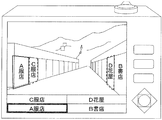
図72は、特許文献1に開示された景観ラベリングシステムの構成図である。景観ラベリング端末は、撮影時に位置、カメラ角度、焦点距離等を撮影時に取得し、景観ラベリングセンターへ送信する。景観ラベリングセンターは、コンピュータ上の地図データを3次元データとして予め作成している。景観ラベリングセンターは、景観ラベリング端末から受信した情報を元に、コンピュータ上の三次元空間内で、画像撮影時の景観ラベリング端末から見える景観のコンピュータグラフィック画像を作成する。作成したコンピュータグラフィック画像より、景観の構造物名等に代表される地理的情報を取得し、景観ラベリング端末へ送信する。
FIG. 72 is a configuration diagram of the landscape labeling system disclosed in
景観ラベリング端末は、受信した地理的情報を実風景である画像の構造物が写っていると思われる位置に重複表示する。
しかしながら、特許文献1では、実風景と撮影画像の対応を明確にする目的でランドマークを重複表示するため、画像中に重複表示された建物名や施設名などのランドマーク情報を閲覧すること自体が目的の場合に、撮影された画像に含まれるランドマークの数が多いと、撮影機に表示されるランドマーク名の数も多くなる。しかし撮影機の表示画像が小さいため多くのランドマークの名称を表示すると見難くなるため、利用者にとって閲覧性が悪くなるという課題を有していた。例えば、ビル街で遠方のビルを撮影した場合には、近傍のビルの名称がすべて表示され、ユーザにとって建物とランドマークの対応が取りづらくなるという課題を有していた。
However, in
また、従来撮影機と構造物の間の距離と、撮影機から得られた構造物の画像との垂直方向の相関が無いために、実際の構造物の位置にランドマーク情報を重複表示させることは困難であるという課題を有していた。特許文献1では、これを解決するために、コンピュータグラフィック画像を作成することによる視野空間の作成を行う。すなわち特許文献1では、撮影した景観のランドマーク情報を取得するために、景観ラベリングセンターでは、コンピュータ上の地図データを三次元のデータとして予め作成しておく。次に、景観ラベリング端末(撮影機)が位置情報、カメラ角と焦点距離、画像サイズ情報を景観ラベリングセンターに送信し、景観ラベリングセンターで、撮影機から見えている景観の視野空間を求め、その視野空間中に存在する構造物情報を取得する。また、構造物の情報を取得するために、撮影機の位置情報、カメラ角と撮影距離、画像サイズ情報が変わる度に視野空間を計算する必要があり、ランドマーク情報を取得するためのサーバの計算量が膨大になってしまう課題を有していた。
In addition, since there is no vertical correlation between the distance between the conventional camera and the structure and the image of the structure obtained from the camera, landmark information can be displayed in duplicate on the actual structure position. Had the problem of being difficult. In
また、特許文献1では撮影機は取得した画像を複数の被写体の部分領域に分割する画像処理手段を有する。すなわち、撮影機はエッジ抽出を行う必要があり、撮影機の演算量が膨大になってしまうという課題を有していた。 In Japanese Patent Application Laid-Open No. H10-228707, the photographing machine has an image processing unit that divides an acquired image into partial areas of a plurality of subjects. That is, the photographing machine needs to perform edge extraction, and has a problem that the amount of calculation of the photographing machine becomes enormous.
本発明は、このような実情に鑑みてなされたもので、上記課題を解決するために、本発明は以下の手段を採用する。 The present invention has been made in view of such circumstances, and in order to solve the above problems, the present invention employs the following means.
すなわち、画像撮影装置は、デジタル画像を撮影する撮影手段と、前記撮影手段で撮影した前記デジタル画像に含まれる各オブジェクトにそれぞれ対応する複数の付加情報を保持する予め定められた保持装置から当該複数の付加情報を取得する付加情報取得手段と、前記付加情報取得手段で取得した当該複数の付加情報から、表示する付加情報を選択する選択手段と、前記撮影手段で撮影した前記デジタル画像と共に、当該複数の付加情報のうちで、前記選択手段で選択した付加情報のみを表示する表示手段とを有する。 That is, the image photographing device includes a plurality of the photographing means for photographing a digital image and the predetermined holding device for retaining a plurality of additional information respectively corresponding to each object included in the digital image photographed by the photographing means. The additional information acquisition means for acquiring the additional information, the selection means for selecting additional information to be displayed from the plurality of additional information acquired by the additional information acquisition means, and the digital image captured by the imaging means, Display means for displaying only the additional information selected by the selection means among the plurality of additional information.
これにより、有用な付加情報は表示されつつも、表示される付加情報が多過ぎることが回避されて、適切な数の付加情報が表示されるようにできる。 Thereby, while useful additional information is displayed, it can be avoided that too much additional information is displayed, and an appropriate number of additional information is displayed.
本発明によれば、表示される付加情報が多過ぎることが回避されて、適切な数の付加情報が表示されるようにできる。 According to the present invention, it is possible to avoid an excessive amount of additional information being displayed and to display an appropriate number of additional information.
以下、本発明の一実施の形態に係る景観フィルタリングシステムについて図面を参照しながら説明する。 Hereinafter, a landscape filtering system according to an embodiment of the present invention will be described with reference to the drawings.
(第1の実施形態)
第1の実施形態に係る画像撮影装置(撮影機102)は、デジタル画像を撮影する撮影部(撮影部114、画像処理部115)と、前記撮影部で撮影した前記デジタル画像に含まれる各オブジェクトにそれぞれ対応する複数の付加情報を保持する予め定められた保持装置(地図サーバ120)から当該複数の付加情報を取得する付加情報取得部(通信部112)と、前記付加情報取得部で取得した当該複数の付加情報から、表示する付加情報を選択する選択部(表示情報抽出部113)と、前記撮影部で撮影した前記デジタル画像と共に、当該複数の付加情報のうちで、前記選択部で選択した付加情報のみを表示する表示部(重複表示処理部116、表示部117)とを有する画像撮影装置である。
(First embodiment)
An image photographing apparatus (photographer 102) according to the first embodiment includes a photographing unit (photographing
このため、対応するオブジェクトがデジタル画像に含まれる全ての付加情報のうちの、選択された有用な付加情報のみがデジタル画像と共に表示され、有用な付加情報は表示されつつも、表示される付加情報が多過ぎることが回避されて、適切な数の付加情報が表示されるようにできる。 Therefore, only the useful additional information selected among the additional information whose corresponding object is included in the digital image is displayed together with the digital image, and the additional information displayed while the useful additional information is displayed. It is possible to avoid an excessive amount of and display an appropriate number of additional information.
また、第1の実施形態に係る画像撮影装置は、当該画像撮影装置は、前記撮影部で前記デジタル画像を撮影した撮影位置を取得する撮影位置取得部(位置情報取得部103)と、前記撮影部で前記デジタル画像を撮影した撮影方向を取得する撮影方向取得部(撮影方向取得部106)とを備え、前記付加情報取得部は、撮影位置および撮影方向に対応付けて、当該撮影位置から当該撮影方向を向いてデジタル画像に撮影されるオブジェクトの付加情報を記憶する予め定められた付加情報記憶装置(地図サーバ120)から、取得された前記撮影位置と、前記撮影方向とに対応付けられた各付加情報を取得することを特徴とする画像撮影装置である。 In addition, the image photographing device according to the first embodiment includes a photographing position obtaining unit (position information obtaining unit 103) that obtains a photographing position where the digital image is photographed by the photographing unit, and the photographing unit. A shooting direction acquisition unit (shooting direction acquisition unit 106) that acquires a shooting direction in which the digital image was shot by the unit, and the additional information acquisition unit associates the shooting position and the shooting direction with the shooting position from the shooting position. Corresponding to the shooting position and the shooting direction acquired from a predetermined additional information storage device (map server 120) that stores additional information of the object to be shot in the digital image facing the shooting direction. An image photographing apparatus characterized by acquiring each additional information.
このため、デジタル画像に撮影された領域を特定し、その領域に位置が含まれるオブジェクトである、デジタル画像に含まれる各オブジェクトを特定する、撮影位置および撮影方向がそれぞれ取得されて、取得されたそれら撮影位置および撮影方向に対応した、それら、含まれる各オブジェクトの各付加情報が画像撮影装置に取得され、これにより、例えば、デジタル画像が付加情報記憶装置に送信され、送信されたデジタル画像から、撮影位置や撮影方向が不明なままで、そのデジタル画像の複雑な解析処理などにより、必要な付加情報が画像撮影装置に取得されるなどの、複雑な仕組みが必要なくなり、簡単な構成により、必要な付加情報が画像撮影装置に取得されるようにできる。 For this reason, an area photographed in the digital image is specified, and each object included in the digital image, which is an object whose position is included in the area, is acquired and acquired. The additional information of each of the included objects corresponding to the shooting position and the shooting direction is acquired by the image shooting device, whereby, for example, a digital image is transmitted to the additional information storage device, and from the transmitted digital image With a simple configuration, the camera position and shooting direction remain unknown, and no complicated mechanism is required, such as the necessary additional information being acquired by the image capturing device through complicated analysis processing of the digital image. Necessary additional information can be acquired by the image capturing apparatus.
また、第1の実施形態に係る画像撮影装置は、前記複数の付加情報は、それぞれ、当該付加情報に係る前記オブジェクトの位置を含み、前記撮影部は、前記デジタル画像を撮影したズーム比を取得し、前記選択部は、取得された前記ズーム比に対して、大きく拡大するズーム比ほど遠い距離に対応付ける、ズーム比と距離との間の予め定められたズーム比対応関係が対応づける距離が、取得された前記撮影位置からの距離である位置が含まれる付加情報を選択することを特徴とする画像撮影装置である。 In the image capturing device according to the first embodiment, each of the plurality of additional information includes a position of the object according to the additional information, and the capturing unit acquires a zoom ratio for capturing the digital image. Then, the selection unit obtains a distance associated with a predetermined zoom ratio correspondence between the zoom ratio and the distance, which is associated with a distance that is farther as the zoom ratio that is greatly enlarged with respect to the acquired zoom ratio. The image photographing apparatus is characterized by selecting additional information including a position that is a distance from the photographed position.
このため、より大きく拡大されるズーム比での撮影がされて、より遠くの距離の位置のオブジェクトがユーザに関心を持たれる場合には、より遠くの位置のオブジェクトの付加情報が表示され、ユーザに関心が持たれているオブジェクトの付加情報がより的確に表示されるようにできる。 For this reason, when shooting is performed with a zoom ratio that is larger and the object at a farther distance is interested in the user, additional information on the object at a farther distance is displayed, and the user It is possible to display the additional information of the object in which the user is interested in more accurately.
また、第1の実施形態に係る画像撮影装置は、前記撮影部で前記デジタル画像を撮影した撮影方向を取得する撮影方向取得部と、前記選択部は、取得された前記撮影位置と前記撮影方向と前記ズーム比とを基にして、取得された当該撮影位置からの距離が、取得された前記ズーム比に対応付けられた範囲に含まれ、かつ、取得された当該撮影位置からの方向が、前記撮影方向である位置範囲を算出し、算出された前記位置範囲に含まれる位置が含まれた付加情報を選択することを特徴とする画像撮影装置である。 In addition, the image capturing apparatus according to the first embodiment includes a capturing direction acquisition unit that acquires a capturing direction in which the digital image is captured by the capturing unit, and the selection unit includes the acquired capturing position and the capturing direction. Based on the zoom ratio and the acquired distance from the shooting position is included in a range associated with the acquired zoom ratio, and the direction from the acquired shooting position is An image photographing apparatus, wherein a position range that is the photographing direction is calculated, and additional information including a position included in the calculated position range is selected.
このため、撮影がされた撮影位置から、撮影がされた撮影方向である位置範囲の位置の付加情報が表示されることにより、付加情報が表示されるオブジェクトの位置までの距離だけでなく、撮影された撮影位置および撮影方向までも、有用であることを示す付加情報が選択され、表示がされて、より的確、確実に、有用である付加情報が選択され、表示されるようにできる。 For this reason, by displaying additional information on the position of the position range that is the shooting direction from which the image was taken, not only the distance to the position of the object on which the additional information is displayed, but also the shooting position. The additional information indicating that it is useful is selected and displayed even for the shooting position and the shooting direction, and the additional information that is useful can be selected and displayed more accurately and reliably.
しかも、適度な広がりのある位置範囲に位置のある付加情報が表示されて、有用な付加情報がより確実に表示されるようにできる。 In addition, additional information having a position in a position range having an appropriate spread is displayed, so that useful additional information can be displayed more reliably.
また、第1の実施形態に係る画像撮影装置は、前記画像撮影装置は、さらに、撮影者が当該画像撮影装置を動かした手振れを検出する手振れ検出部を有し、前記表示部は、前記手振れ検出部が撮影者の手振れを検出している間は、検出の開始時に前記表示部が表示していた前記付加情報を継続して表示することを特徴とする画像撮影装置である。 The image capturing apparatus according to the first embodiment further includes a camera shake detecting unit that detects a camera shake that a photographer moves the image capturing apparatus, and the display unit includes the camera shake. While the detection unit detects a camera shake of the photographer, the additional information displayed on the display unit at the start of detection is continuously displayed.
このため、手振れが検出されて、取得されるズーム比が、表示される付加情報の選択に用いるのに適切でない間は、適切でなくなる直前の、検出の開始時において表示されていた付加情報が継続して表示されて、表示が乱れてしまうことを回避し、整った表示が継続されて、手振れがあったときでも、適切に表示が行われるようにできる。 For this reason, as long as camera shake is detected and the acquired zoom ratio is not appropriate for use in selecting the additional information to be displayed, the additional information displayed at the start of detection immediately before it becomes inappropriate It is possible to prevent the display from being disturbed by being continuously displayed, and to maintain a proper display so that even when there is a camera shake, the display is appropriately performed.
また、第1の実施形態に係る画像撮影装置は、前記複数の付加情報は、それぞれ、当該付加情報に係る前記オブジェクトの位置を含み、前記撮影部は、前記デジタル画像を撮影した焦点距離を取得し、前記選択部は、取得された前記焦点距離に対して、遠い焦点距離ほど遠い距離に対応付ける、焦点距離と距離との間の予め定められた焦点距離対応関係が対応づける距離が、取得された前記撮影位置からの距離である位置が含まれる付加情報を選択することを特徴とする画像撮影装置である。 Further, in the image photographing device according to the first embodiment, each of the plurality of additional information includes the position of the object according to the additional information, and the photographing unit acquires a focal length obtained by photographing the digital image. Then, the selection unit acquires a distance that is associated with a predetermined focal length correspondence between a focal length and a distance, which is associated with a far distance as the focal length is farther, with respect to the acquired focal length. The image photographing apparatus is characterized by selecting additional information including a position that is a distance from the photographing position.
このため、より遠い距離が撮影される、より遠い焦点距離での撮影がされて、より遠くの距離の位置のオブジェクトがユーザに関心を持たれている場合に、より遠くの位置のオブジェクトの付加情報が表示され、ユーザに関心が持たれているオブジェクトの付加情報がより的確、確実に表示されるようにできる。 For this reason, when an object at a far distance is photographed at a far focal distance and an object at a far distance is interested in the user, an object at a far place is added. The information is displayed, and the additional information of the object in which the user is interested can be displayed more accurately and reliably.
また、第1の実施形態に係る画像撮影装置は、前記画像撮影装置は、さらに、撮影中の人物を認識する人物認識部と、前記人物認識部で認識した人物に焦点を合わせる人物合焦部とを有し、前記撮影部は、前記デジタル画像を撮影したズーム比を取得し、前記選択部は、前記人物合焦部が人物に焦点を合わせて前記撮影部が前記デジタル画像を撮影した場合には、取得された前記ズーム比に基づいて、当該ズーム比に対して、大きく拡大するズーム比ほど遠い距離に対応付ける、ズーム比と距離との間の予め定められたズーム比対応関係が対応付ける距離が、取得された前記撮影位置からの距離である位置の部付加情報を選択することを特徴とする画像撮影装置である。 The image capturing device according to the first embodiment further includes a person recognizing unit that recognizes a person being photographed, and a person focusing unit that focuses on the person recognized by the person recognizing unit. And the photographing unit acquires a zoom ratio obtained by photographing the digital image, and the selecting unit is configured to focus the person on the person focusing unit and photograph the digital image. Is based on the acquired zoom ratio, and a distance to which a predetermined zoom ratio correspondence between the zoom ratio and the distance is associated with a distance that is farther as the zoom ratio is greatly enlarged with respect to the zoom ratio. The image photographing apparatus is characterized in that it selects part additional information at a position that is a distance from the obtained photographing position.
このため、人物認識部により人物が認識されて、人物に人物合焦部により焦点が合わせられた場合の、ユーザに有用な付加情報を示さない焦点距離での撮影がされた場合には、焦点距離ではなくズーム比に基づいて選択がされ、人物が認識されて焦点が人物に合わせられる機能を設けつつも、ズーム比による付加情報の選択がされることにより、適切に付加情報が選択され、表示されるようにできる。 For this reason, when a person is recognized by the person recognition unit and focused on the person by the person focusing unit, when shooting is performed at a focal length that does not indicate additional information useful to the user, Selection is made based on the zoom ratio rather than the distance, and the additional information is appropriately selected by selecting the additional information based on the zoom ratio while providing the function of recognizing the person and focusing on the person. It can be displayed.
また、第1の実施形態に係る画像撮影装置は、前記付加情報は、それぞれ、当該付加情報に係る前記オブジェクトの位置を含み、前記撮影部は、前記デジタル画像を撮影した視野角を取得し、前記選択部は、取得された前記撮影位置から、取得された前記視野角を見た予め定められた範囲に位置が含まれる付加情報を選択することを特徴とする画像撮影装置である。 Further, in the image capturing device according to the first embodiment, each of the additional information includes a position of the object according to the additional information, and the capturing unit acquires a viewing angle obtained by capturing the digital image, The selection unit is an image photographing device that selects, from the acquired photographing position, additional information whose position is included in a predetermined range when the acquired viewing angle is viewed.
このため、撮影された撮影位置から、撮影された視野角を見た、デジタル画像が表示される際に関心を持たれる予め定められた範囲に位置があるオブジェクトの付加情報が選択されて、より的確に適切な付加情報が選択され、表示されるようにできる。 For this reason, the additional information of the object whose position is within a predetermined range that is of interest when the digital image is displayed is selected from the shooting position where the viewing angle is viewed. Appropriate additional information can be accurately selected and displayed.
また、第1の実施形態に係る画像撮影装置は、前記選択部は、取得した前記撮影位置から、取得した前記視野角を見た領域が予め定められた単位角度毎に分割された各部分領域毎に、それぞれ当該部分領域に位置が含まれる予め定められた個数の前記付加情報を選択することを特徴とする画像撮影装置である。 Further, in the image capturing device according to the first embodiment, the selection unit includes each partial region obtained by dividing the region obtained by viewing the acquired viewing angle from the acquired capturing position for each predetermined unit angle. Each of the image capturing apparatuses is characterized by selecting a predetermined number of the additional information each including a position in the partial area.
また、第1の実施形態に係る画像撮影装置は、前記付加情報は、下位の階層は、当該下位の階層よりも上位である上位の階層に含まれるオブジェクトの一部分よりなるオブジェクトが含まれる複数の階層のうちから、当該付加情報のオブジェクトが含まれる階層を特定する階層情報を含み、前記選択部は、前記複数の階層から、前記部分領域に位置が含まれる付加情報のうちで当該各選択階層のうち何れかを特定する階層情報が含まれる付加情報の個数の合計数が予め定められた個数以下である1以上の選択階層を選択し、選択した各選択階層の前記付加情報を選択することを特徴とする画像撮影装置である。 In the image capturing device according to the first embodiment, the additional information includes a plurality of objects in which a lower layer includes a part of an object included in a higher layer that is higher than the lower layer. Among the hierarchies, hierarchy information that identifies a hierarchy in which the object of the additional information is included is included. Selecting one or more selected hierarchies in which the total number of additional information including hierarchy information specifying any of them is equal to or less than a predetermined number, and selecting the additional information of each selected selected hierarchies Is an image capturing device characterized by the above.
このため、個数に対応する適切な階層の付加情報が選択され、表示されるようにできる。 For this reason, additional information of an appropriate hierarchy corresponding to the number can be selected and displayed.
また、第1の実施形態に係る画像撮影装置は、前記複数の付加情報は、それぞれ当該付加情報に係る前記オブジェクトの位置を含み、前記選択部は、取得された前記撮影位置から、取得された前記撮影方向を見た予め定められた視野空間に、前記位置が含まれる付加情報を選択することを特徴とする画像撮影装置である。 In the image capturing device according to the first embodiment, each of the plurality of additional information includes a position of the object related to the additional information, and the selection unit is acquired from the acquired shooting position. The image photographing apparatus is characterized in that the additional information including the position is selected in a predetermined visual field space when the photographing direction is viewed.
また、第1の実施形態に係る画像撮影装置は、前記選択部は、前記視野空間が分割された予め定められたメッシュ毎に、それぞれ、当該メッシュに含まれる位置が含まれる付加情報を選択することを特徴とする画像撮影装置である。 Further, in the image capturing device according to the first embodiment, the selection unit selects, for each predetermined mesh obtained by dividing the visual field space, additional information including a position included in the mesh. This is an image photographing apparatus characterized by the above.
また、第1の実施形態に係る画像撮影装置は、前記選択部は、前記視野空間が分割された、取得された前記撮影位置からの距離が互いに異なる複数の部分領域ごとにそれぞれ予め定められた個数の当該部分領域に含まれる位置を含む付加情報を選択することを特徴とする画像撮影装置である。 In the image photographing device according to the first embodiment, the selection unit is predetermined for each of a plurality of partial regions in which the visual field space is divided and the distances from the obtained photographing positions are different from each other. An image photographing apparatus is characterized in that additional information including positions included in the number of partial areas is selected.
また、第1の実施形態に係る画像撮影装置は、前記付加情報は、下位の階層は、当該下位の階層よりも上位である上位の階層に含まれるオブジェクトの一部分よりなるオブジェクトが含まれる複数の階層のうちから、当該付加情報のオブジェクトが含まれる階層を特定する階層情報を含み、前記選択部は、前記複数の階層のうちから、分割された前記部分領域に含まれる位置を含む選択情報のうちで当該各選択階層を特定する階層情報が含まれる選択情報の合計数が前記予め定められた個数以下となる1以上の選択階層を選択し、選択した各選択階層の前記付加情報を選択することを特徴とする画像撮影装置である。 In the image capturing device according to the first embodiment, the additional information includes a plurality of objects in which a lower layer includes a part of an object included in a higher layer that is higher than the lower layer. Among the hierarchies, it includes hierarchy information for specifying a hierarchy in which the object of the additional information is included, and the selection unit is configured to select selection information including a position included in the divided partial area from the plurality of hierarchies. Among them, one or more selected hierarchies in which the total number of selection information including the hierarchy information specifying each selected hierarchies is equal to or less than the predetermined number is selected, and the additional information of each selected selected hierarchies is selected. This is an image photographing apparatus characterized by the above.
また、第1の実施形態に係る画像撮影装置は、前記選択部は、分割された前記部分領域に位置が含まれる付加情報が予め定められた個数を超える場合は、当該部分領域の各付加情報のうちで、取得された前記撮影方向からの角度が最も小さい位置を含む付加情報から、前記予め定められた個数番目に小さい位置を含む付加情報まで各付加情報を選択することを特徴とする画像撮影装置である。 In addition, in the image capturing device according to the first embodiment, when the additional information whose position is included in the divided partial area exceeds a predetermined number, the selection unit includes each additional information of the partial area. Wherein the additional information is selected from the additional information including the acquired position with the smallest angle from the shooting direction to the additional information including the predetermined number of the smallest positions. It is a photographing device.
また、第1の実施形態に係る画像撮影装置は、前記複数の付加情報は、それぞれ当該付加情報に係る前記オブジェクトの分類を含み、前記選択部は、前記付加情報取得部で取得した複数の付加情報のうちから、分類が予め定められた分類である付加情報を選択することを特徴とする画像撮影装置である。 In the image capturing device according to the first embodiment, the plurality of additional information each include a classification of the object related to the additional information, and the selection unit includes a plurality of additional information acquired by the additional information acquisition unit. The image photographing apparatus is characterized in that, from information, additional information having a predetermined classification is selected.
また、第1の実施形態に係る画像撮影装置は、前記分類は、ジャンル、人気順位、検索順位の少なくともいずれか1つを含むことを特徴とする画像撮影装置である。 Further, the image photographing apparatus according to the first embodiment is an image photographing apparatus characterized in that the classification includes at least one of a genre, a popularity rank, and a search rank.
また、第1の実施形態に係る画像撮影装置は、前記画像撮影装置は、さらに、ユーザを識別するユーザ識別情報を保持する識別情報保持部と、保持される前記ユーザ識別情報を、ユーザ識別情報と分類との予め定められた分類対応情報を保持する情報提供サーバに送信し、前記情報提供サーバから、送信した前記識別情報に前記分類対応情報が対応させる分類を取得するユーザ情報取得部とを有し、前記選択部は、取得された前記分類を前記予め定められた分類として用いて、付加情報を選択することを特徴とする画像撮影装置である。 In the image photographing device according to the first embodiment, the image photographing device further includes an identification information holding unit that holds user identification information for identifying a user, and the user identification information held by the user identification information. And a user information acquisition unit that acquires a classification that the classification correspondence information corresponds to the transmitted identification information from the information provision server. And the selection unit selects additional information using the acquired classification as the predetermined classification.
また、第1の実施形態に係る画像撮影装置は、前記画像撮影装置は、さらに、前記予め定められた分類を、前記予め定められた分類としてユーザから受け付けるユーザ情報受付部を有し、前記選択部は、付加情報に含まれる分類と、受け付けられた分類とに基づいて、付加情報を選択することを特徴とする画像撮影装置である。 The image capturing device according to the first embodiment further includes a user information receiving unit that receives the predetermined classification from the user as the predetermined classification. The image capturing apparatus is characterized in that the additional information is selected based on the classification included in the additional information and the accepted classification.
また、第1の実施形態に係る画像撮影装置は、前記複数の付加情報は、それぞれ当該付加情報に係る前記オブジェクトの高さを含み、前記選択部は、含まれる高さが予め定められた高さ以上である付加情報を選択することを特徴とする画像撮影装置である。 In the image capturing device according to the first embodiment, each of the plurality of additional information includes a height of the object related to the additional information, and the selection unit includes a predetermined height. The image capturing apparatus is characterized by selecting additional information that is greater than or equal to the above.
このため、見え易く、関心がもたれ易い、高さが高いオブジェクトの付加情報が選択されて、表示されて、関心がもたれ易い適切な付加情報が的確に表示されるようにできる。 For this reason, it is possible to select and display the additional information of the object that is easy to see, easy to be interested, and high in height, and appropriately display the appropriate additional information that is easy to be interested.
また、第1の実施形態に係る画像撮影装置は、前記選択部は、取得された前記撮影位置から、取得された前記撮影方向を見た予め定められた視野空間が、前記撮影位置からの距離が互いに異なる予め定められた複数の部分領域に分割された各部分領域毎に、それぞれ、当該部分領域に位置が含まれる予め定められた個数の付加情報を選択することを特徴とする画像撮影装置である。 Further, in the image capturing device according to the first embodiment, the selection unit is configured such that a predetermined visual field space in which the acquired shooting direction is viewed from the acquired shooting position is a distance from the shooting position. An image photographing apparatus that selects, for each partial area divided into a plurality of predetermined partial areas different from each other, a predetermined number of additional information whose positions are included in the partial areas, respectively. It is.
また、第1の実施形態に係る画像撮影装置は、前記複数の付加情報は、それぞれ、当該付加情報に係る前記オブジェクトの高さにより、前記複数の付加情報が複数の高さ階層に分類された高さ階層分類を含み、前記選択部は、前記各部分領域ごとにそれぞれ、当該部分領域に対応する前記予め定められた個数に対応する高さ階層分類を選択し、選択した高さ階層分類が含まれる付加情報を選択することを特徴とする画像撮影装置である。 In the image capturing device according to the first embodiment, the plurality of additional information is classified into a plurality of height layers according to the height of the object related to the additional information. A height hierarchy classification, and the selection unit selects a height hierarchy classification corresponding to the predetermined number corresponding to the partial area for each partial area, and the selected height hierarchy classification An image photographing apparatus is characterized in that additional information included is selected.
また、第1の実施形態に係る画像撮影装置は、前記選択部は、部分領域に位置が含まれる付加情報の個数が前記予め定められた個数を超える場合は、当該各付加情報のうちで最も高い高さの付加情報から、前記予め定められた個数番目に高い高さの付加情報までの各付加情報を選択することを特徴とする画像撮影装置である。 In addition, in the image capturing device according to the first embodiment, the selection unit may be the most of the additional information when the number of additional information whose position is included in the partial area exceeds the predetermined number. The image photographing apparatus is characterized by selecting each piece of additional information from the high height additional information to the predetermined number of pieces of the highest additional information.
また、第1の実施形態に係る画像撮影装置は、前記複数の付加情報は、それぞれ当該付加情報に係る前記オブジェクトの位置を含み、前記画像撮影装置は、更に、前記表示部が表示を行う際の解像度を取得する解像度取得部を有し、前記選択部は、取得された前記撮影位置と前記撮影方向と前記解像度とに基づいて、取得された前記撮影位置から、取得された前記撮影方向を見た予め定められた領域に前記位置が含まれる付加情報のうちで、解像度が大きいほど多い個数に対応付ける、解像度と個数との間の予め定められた解像度対応関係が、取得された当該解像度に対応付ける個数の付加情報を選択することを特徴とする画像撮影装置である。 In the image capturing device according to the first embodiment, each of the plurality of additional information includes a position of the object related to the additional information, and the image capturing device is further configured to display the display unit. A resolution acquisition unit that acquires the resolution of the image, and the selection unit determines the acquired shooting direction from the acquired shooting position based on the acquired shooting position, the shooting direction, and the resolution. Among the additional information in which the position is included in the predetermined area that has been viewed, the predetermined resolution correspondence relationship between the resolution and the number that is associated with a larger number as the resolution is larger is the acquired resolution. An image photographing apparatus is characterized in that the number of additional information to be associated is selected.
また、第1の実施形態に係る画像撮影装置は、前記付加情報は、それぞれ当該付加情報に係る前記オブジェクトの位置を含み、前記画像撮影装置は、前記表示部の表示領域の大きさを取得する表示領域情報検知部を有し、前記選択部は、取得された前記撮影位置と前記撮影方向と前記表示領域の大きさとに基づいて、取得された前記撮影位置から、取得された前記撮影方向を見た予め定められた領域に前記位置が含まれる付加情報のうちで、表示領域の大きさが大きいほど多い個数に対応付ける、表示領域の大きさと個数との間の予め定められた表示領域対応関係が、取得された当該表示領域の大きさに対応付ける個数の付加情報を選択することを特徴とする画像撮影装置である。 In the image capturing device according to the first embodiment, the additional information includes the position of the object related to the additional information, and the image capturing device acquires the size of the display area of the display unit. A display area information detection unit, and the selection unit determines the acquired shooting direction from the acquired shooting position based on the acquired shooting position, the shooting direction, and the size of the display area. Predetermined display area correspondence between the size and the number of display areas, which corresponds to a larger number as the size of the display area is larger, among the additional information in which the position is included in the predetermined area seen. Is an image capturing apparatus that selects the number of additional information corresponding to the size of the acquired display area.
また、第1の実施形態に係る画像撮影装置は、当該画像撮影装置は、更に、付加情報を識別する識別子を、付加情報の詳細情報を保持する予め定められた詳細情報保持装置に送信し、送信する前記識別子により識別される前記付加情報の詳細情報を当該詳細情報保持装置から取得する詳細情報取得部を備えることを特徴とする画像撮影装置である。 Further, in the image photographing device according to the first embodiment, the image photographing device further transmits an identifier for identifying the additional information to a predetermined detailed information holding device that holds the detailed information of the additional information, An image photographing apparatus comprising a detailed information acquisition unit that acquires detailed information of the additional information identified by the identifier to be transmitted from the detailed information holding device.
また、第1の実施形態に係る画像撮影装置は、当該画像撮影装置は、更に、付加情報を識別する識別子を、付加情報の詳細情報の保存アドレスを保持する予め定められた保存アドレス保持装置に送信し、送信した前記識別子により識別される付加情報の詳細情報の保存アドレスを当該保存アドレス保持装置から取得し、取得した前記保存アドレスが示すアクセス先にアクセスすることで、当該アクセス先から前記詳細情報を取得する詳細情報取得部を備えることを特徴とする画像撮影装置である。 Further, in the image photographing device according to the first embodiment, the image photographing device further assigns an identifier for identifying additional information to a predetermined storage address holding device that holds a storage address of detailed information of the additional information. Transmitting the storage address of the detailed information of the additional information identified by the transmitted identifier from the storage address holding device, and accessing the access destination indicated by the acquired storage address, so that the details from the access destination An image capturing apparatus comprising a detailed information acquisition unit that acquires information.
また、第1の実施形態に係る画像撮影装置は、前記付加情報に対応する詳細情報は、当該詳細情報に係る付加情報が有している情報以外の他の情報であり、かつ、当該オブジェクトに関する、インターネット上のウェブコンテンツと、当該オブジェクトのコンピュータグラフィックス(CG)モデルと、前記撮影に先立って撮影された、当該オブジェクトが写っている類似画像との少なくとも何れか1つを含み、前記詳細情報取得部は、前記付加情報が有する前記識別子によって識別される、当該画像撮影装置が接続する予め定められたネットワーク上のサーバに格納された前記詳細情報を取得することを特徴とする画像撮影装置である。 Further, in the image capturing device according to the first embodiment, the detailed information corresponding to the additional information is information other than the information included in the additional information related to the detailed information, and relates to the object The detailed information including at least one of web content on the Internet, a computer graphics (CG) model of the object, and a similar image in which the object is photographed before the photographing. The acquisition unit acquires the detailed information stored in a server on a predetermined network connected to the image capturing apparatus, which is identified by the identifier included in the additional information. is there.
また、第1の実施形態に係る画像撮影装置は、前記画像撮影装置は、さらに、操作者の詳細情報取得要求を受け付ける詳細情報要求受付部を有し、前記詳細情報取得部は、前記詳細情報取得要求が受け付けられた場合に、前記詳細情報を取得することを特徴とする画像撮影装置である。 The image capturing apparatus according to the first embodiment further includes a detailed information request receiving unit that receives an operator's detailed information acquisition request, and the detailed information acquiring unit includes the detailed information. When the acquisition request is accepted, the detailed information is acquired.
また、第1の実施形態に係る画像撮影装置は、前記詳細情報要求受付部は、前記デジタル画像に含まれるオブジェクトの画像を拡大させるズーム操作がされた場合に、拡大された前記デジタル画像に写ったオブジェクトの詳細情報の詳細情報取得要求として、当該ズーム操作を受け付けることを特徴とする画像撮影装置である。 Further, in the image capturing device according to the first embodiment, the detailed information request accepting unit is reflected in the enlarged digital image when a zoom operation for enlarging the image of the object included in the digital image is performed. The image capturing apparatus is characterized in that the zoom operation is received as a detailed information acquisition request for the detailed information of the object.
これにより、関心を有するオブジェクトの画像を拡大するズーム操作をする操作だけで、自然、簡単に、詳細情報取得要求が受け付けられるようにできる。 As a result, a detailed information acquisition request can be accepted naturally and simply by performing an operation of zooming to enlarge an image of an object of interest.
また、第1の実施形態に係る画像撮影装置は、前記複数の付加情報は、それぞれ、当該付加情報に係る前記オブジェクトの位置を含み、前記選択部は、前記撮影部がデジタル画像を撮影するズーム比が操作者の操作により変更されると、変更後のズーム比に基づいて改めて前記表示部に表示される付加情報を選択し、前記詳細情報要求部は、前記操作により変更されたズーム比に基づき選択された付加情報の数が予め定められた個数以下の場合に、前記詳細情報取得要求として当該操作を受け付けることを特徴とする画像撮影装置である。 Further, in the image capturing device according to the first embodiment, each of the plurality of additional information includes a position of the object related to the additional information, and the selection unit is a zoom for capturing the digital image by the capturing unit. When the ratio is changed by the operation of the operator, the additional information displayed on the display unit is selected again based on the changed zoom ratio, and the detailed information request unit sets the zoom ratio changed by the operation. When the number of additional information selected based on the number is equal to or less than a predetermined number, the image capturing apparatus accepts the operation as the detailed information acquisition request.
また、第1の実施形態に係る付加情報提供サーバ(地図サーバ120)は、オブジェクトの付加情報を保持するデータベース(地図データベース118)と、デジタル画像が撮影された撮影位置と撮影方向とを予め定められた他の装置から受信する受信部と、前記受信情報より、付加情報に係るオブジェクトの位置が受信された撮影位置と撮影方向とに対応する位置か否かに応じて、前記デジタル画像に含まれる各オブジェクトに対応する複数の付加情報を前記データベースより抽出する付加情報抽出部(ランドマーク情報抽出部119)と、抽出された前記付加情報を前記他の装置に送信する送信部とを有する付加情報提供サーバである。 In addition, the additional information providing server (map server 120) according to the first embodiment predetermines a database (map database 118) that holds additional information of an object, a shooting position and a shooting direction where a digital image is shot. Included in the digital image according to whether the position of the object related to the additional information is a position corresponding to the received shooting position and shooting direction from the received information. An additional information extraction unit (landmark information extraction unit 119) that extracts a plurality of additional information corresponding to each object from the database, and a transmission unit that transmits the extracted additional information to the other device It is an information providing server.
また、第1の実施形態に係る付加情報提供サーバは、前記付加情報抽出部は、前記複数の付加情報を抽出した後に、前記デジタル画像の領域の周辺領域に位置が含まれるオブジェクトの前記付加情報たる周辺付加情報を抽出し、前記送信部は、抽出された付加情報と、抽出された周辺付加情報とを前記他の装置に送信することを特徴とする付加情報提供サーバである。 Further, in the additional information providing server according to the first embodiment, the additional information extracting unit extracts the plurality of additional information, and then the additional information of the object whose position is included in a peripheral area of the digital image area. The peripheral additional information is extracted, and the transmitting unit transmits the extracted additional information and the extracted peripheral additional information to the other device.
また、第1の実施形態に係る付加情報提供サーバは、前記付加情報提供サーバは、前記他の装置から、受信された前記撮影位置から、受信された前記撮影方向を向いて撮影された撮影のズーム比を受信し、受信された前記撮影位置から、受信された撮影方向を向いた予め定められた位置にある領域のうちの、受信されたズーム比に対して、大きく拡大するズーム比ほど遠い距離に対応付ける、ズーム比と距離との予め定められたズーム比対応関係が対応づける距離が、受信された前記撮影位置からある予め定められた部分領域に位置が含まれるオブジェクトの付加情報を前記データベースより抽出することを特徴とする付加情報提供サーバである。 Further, the additional information providing server according to the first embodiment is configured such that the additional information providing server is configured to capture a photograph taken in the photographing direction received from the photographing position received from the other device. The zoom ratio is received, and the distance from the received shooting position that is farther as the zoom ratio that is greatly enlarged with respect to the received zoom ratio in the area at the predetermined position facing the received shooting direction. From the database, additional information of an object whose position is included in a predetermined partial area corresponding to the distance from which the predetermined zoom ratio correspondence between the zoom ratio and the distance is associated with An additional information providing server characterized by extracting.
また、第1の実施形態に係る付加情報提供サーバは、前記付加情報提供サーバは、前記受信部は、前記デジタル画像が撮影された際の焦点距離を受信し、前記付加情報抽出部は、受信された前記撮影位置から、受信された撮影方向を向いた予め定められた領域のうちの、受信された焦点距離に対して、遠い焦点距離ほど遠い距離に対応付ける、焦点距離と距離との予め定められた焦点距離対応関係が対応づける距離が、受信された前記撮影位置からある予め定められた部分領域に位置が含まれるオブジェクトの付加情報を前記データベースより抽出することを特徴とする付加情報提供サーバである。 In the additional information providing server according to the first embodiment, the additional information providing server, the receiving unit receives a focal length when the digital image is taken, and the additional information extracting unit receives The predetermined focal length and distance that correspond to the farther the farther the focal length is than the received focal length of the predetermined region facing the photographing direction received from the photographing position. An additional information providing server that extracts additional information of an object whose position is included in a predetermined partial region from the received photographing position, the distance associated with the corresponding focal distance correspondence from the database. is there.
また、第1の実施形態に係る付加情報提供サーバは、前記受信部は、前記デジタル画像が撮影された際の視野角を受信し、前記付加情報抽出部は、受信された前記撮影位置から、受信された視野角で、受信された撮影方向を向いた予め定められた領域に位置が含まれるオブジェクトの付加情報を前記データベースより抽出することを特徴とする付加情報提供サーバである。 Further, in the additional information providing server according to the first embodiment, the receiving unit receives a viewing angle when the digital image is captured, and the additional information extracting unit is configured to receive from the received imaging position, The additional information providing server is characterized in that additional information of an object whose position is included in a predetermined area facing the photographing direction with the received viewing angle is extracted from the database.
また、第1の実施形態に係る付加情報提供サーバは、前記付加情報は、それぞれ当該付加情報に係る前記オブジェクトの分類を含み、前記付加情報抽出部は、含まれる分類が予め定められた分類である付加情報のみを抽出することを特徴とする付加情報提供サーバである。 In the additional information providing server according to the first embodiment, each of the additional information includes a classification of the object related to the additional information, and the additional information extraction unit is configured to classify the included classification in advance. The additional information providing server is characterized by extracting only certain additional information.
また、第1の実施形態に係る付加情報提供サーバは、前記付加情報は、それぞれ当該付加情報に係る前記オブジェクトの高さを含み、前記付加情報抽出部は、含まれる高さが予め定められた高さ以上である付加情報のみを抽出することを特徴とする付加情報提供サーバである。 In the additional information providing server according to the first embodiment, each of the additional information includes a height of the object related to the additional information, and the additional information extracting unit includes a predetermined height. The additional information providing server is characterized by extracting only additional information that is higher than the height.
また、第1の実施形態に係る付加情報提供サーバは、前記付加情報提供サーバは、前記受信部は、前記デジタル画像が撮影された解像度を受信し、前記付加情報抽出部は、受信された解像度に対して、解像度が大きいほど多い個数に対応付ける、ズーム比と個数との間の予め定められた解像度対応関係が対応づける個数の付加情報のみを抽出することを特徴とする付加情報提供サーバである。 Further, in the additional information providing server according to the first embodiment, the additional information providing server, the receiving unit receives the resolution at which the digital image was taken, and the additional information extracting unit receives the received resolution. On the other hand, the additional information providing server is characterized in that only the number of additional information associated with a predetermined resolution correspondence between the zoom ratio and the number is associated with a larger number as the resolution is higher. .
また、第1の実施形態に係る付加情報提供サーバは、前記付加情報提供サーバは、前記受信部は、前記他の装置から、前記デジタル画像が表示される表示領域の大きさを受信し、前記付加情報抽出部は、受信された前記表示領域の大きさに対して、表示領域の大きさが大きいほど多い個数に対応付ける、表示領域の大きさと個数との間の予め定められた表示領域対応関係が対応づける個数の付加情報のみを抽出することを特徴とする付加情報提供サーバである。 Further, in the additional information providing server according to the first embodiment, in the additional information providing server, the receiving unit receives a size of a display area in which the digital image is displayed from the other device, and The additional information extraction unit associates a larger number of display areas with a larger display area with respect to the received display area size, and a predetermined display area correspondence between the display area size and the number. The additional information providing server is characterized by extracting only the number of additional information associated with the.
また、第1の実施形態に係る付加情報提供サーバは、前記付加情報提供サーバは、さらに、撮影者の属性情報を保持する属性情報保持部と、前記デジタル画像を撮影させた撮影者を識別する識別情報を前記他の装置から受信する識別情報受信部とを更に備え、前記付加情報抽出部は、受信された前記識別情報より識別される前記撮影者の属性情報を前記属性情報保持部より取得する属性情報取得部を有することを特徴とする付加情報提供サーバである。 In the additional information providing server according to the first embodiment, the additional information providing server further identifies an attribute information holding unit that holds the photographer's attribute information, and a photographer who has photographed the digital image. An identification information receiving unit that receives identification information from the other device, and the additional information extraction unit acquires attribute information of the photographer identified from the received identification information from the attribute information holding unit. It is an additional information provision server characterized by having the attribute information acquisition part which performs.
また、第1の実施形態に係る付加情報提供サーバは、前記付加情報を識別する識別子を前記他の装置から受信する識別子受信部と、受信された識別子により識別される前記付加情報の詳細情報が保存された保存アドレスを前記他の装置へ送信する詳細情報送信部とを更に備えることを特徴とする付加情報提供サーバである。 The additional information providing server according to the first embodiment includes an identifier receiving unit that receives an identifier for identifying the additional information from the other device, and detailed information of the additional information identified by the received identifier. The additional information providing server, further comprising: a detailed information transmitting unit that transmits the stored address to the other device.
また、第1の実施形態に係る付加情報提供サーバは、保持される前記付加情報を識別する識別子を受信する識別子受信部と、前記識別子が受信されると、受信された前記識別子によって識別される前記付加情報の詳細情報を予め定められた詳細情報データベースから取得し、取得した詳細情報を前記他の装置に送信する詳細情報送信部とを更に備えることを特徴とする付加情報提供サーバである。 The additional information providing server according to the first embodiment is identified by the identifier receiving unit that receives an identifier for identifying the additional information to be held, and when the identifier is received, by the received identifier. The additional information providing server further comprising: a detailed information transmitting unit that acquires detailed information of the additional information from a predetermined detailed information database and transmits the acquired detailed information to the other device.
また、第1の実施形態に係る付加情報提供サーバは、前記詳細情報は、当該詳細情報に係る付加情報が有している情報以外の他の情報であり、かつ、当該付加情報が対応するオブジェクトに係る、インターネット上のウェブコンテンツと、当該オブジェクトのコンピュータグラフィックス(CG)モデルと、前記撮影より先に撮影された、当該オブジェクトが写っている類似画像とのうちで少なくともいずれか1つを含み、前記付加情報提供サーバは、前記詳細情報を格納するデータベースを有することを特徴とする付加情報提供サーバである。 In the additional information providing server according to the first embodiment, the detailed information is information other than the information included in the additional information related to the detailed information, and the additional information corresponds to the object. At least one of web content on the Internet, a computer graphics (CG) model of the object, and a similar image in which the object is photographed before the photographing. The additional information providing server includes a database for storing the detailed information.
また、第1の実施形態に係る付加情報フィルタリングシステム(システム101)は、デジタル画像を撮影する画像撮影装置(撮影機102)と、当該画像撮影装置により撮影されるオブジェクトの付加情報を当該画像撮影装置に送信する付加情報提供サーバ(地図サーバ120)とを備え、前記画像撮影装置は、前記デジタル画像を撮影する撮影部(撮影部114、画像処理部115)と、前記撮影部でデジタル画像を撮影した撮影位置を取得する撮影位置取得部と、前記撮影部でデジタル画像を撮影した撮影方向を取得する撮影方向取得部と、取得された前記撮影位置と前記撮影方向とを前記付加情報提供サーバへ送信する送信部と、送信をした前記情報提供サーバより、前記撮影部で撮影した前記デジタル画像に含まれる各オブジェクトにそれぞれ対応する複数の付加情報を取得する付加情報取得部と、前記付加情報取得部で取得した複数の付加情報から、表示する付加情報を選択する選択部と、前記撮影部で撮影した前記デジタル画像と共に、前記選択部で選択した付加情報を表示する表示部とを有し、前記付加情報提供サーバは前記撮影位置と前記撮影方向とを前記画像撮影装置から受信する受信部と、前記デジタル画像の前記各オブジェクトに係る前記複数の付加情報を保持するデータベースと、前記受信情報より、付加情報に係るオブジェクトの位置が受信された撮影位置と撮影方向とに対応する位置か否かに応じて、前記複数の付加情報を前記データベースより抽出する付加情報抽出部と、抽出された付加情報を前記画像撮影装置に送信する送信部とを有する付加情報フィルタリングシステムである。
The additional information filtering system (system 101) according to the first embodiment also includes an image photographing device (photographer 102) for photographing a digital image and additional information of an object photographed by the image photographing device. And an additional information providing server (map server 120) for transmitting to the apparatus. The image capturing apparatus captures the digital image by a capturing unit (capturing
また、第1の実施形態に係る画像撮影装置は、前記表示部は、前記選択部で選択した付加情報を、取得された前記撮影位置から、選択された当該付加情報の前記オブジェクトの位置を向いた方角に対応する、当該画像撮影装置の左右方向の箇所に表示することを特徴とする画像撮影装置である。 In the image capturing device according to the first embodiment, the display unit directs the additional information selected by the selection unit from the acquired shooting position to the position of the object of the selected additional information. The image photographing apparatus is characterized in that the image is displayed at a position in the left-right direction of the image photographing apparatus corresponding to the direction of the image.
また、第1の実施形態に係る画像撮影装置は、前記表示部は、前記選択部で選択した付加情報を、取得された前記撮影位置から、選択された当該付加情報の前記オブジェクトの位置までの距離に対応する、当該画像撮影装置の上下方向の箇所に表示することを特徴とする画像撮影装置である。 In the image photographing device according to the first embodiment, the display unit displays the additional information selected by the selection unit from the acquired photographing position to the position of the object of the selected additional information. It is an image photographing device characterized by displaying at a position in the vertical direction of the image photographing device corresponding to the distance.
また、第1の実施形態に係る画像撮影装置は、前記表示部は、前記撮影部で取得した前記デジタル画像を表示すると共に、表示する当該デジタル画像上に枠を表示し、前記選択部で選択した付加情報のうちで、表示された前記枠の内部に含まれるオブジェクトの付加情報のみを、当該デジタル画像と共に表示することを特徴とする画像撮影装置である。 In the image photographing device according to the first embodiment, the display unit displays the digital image acquired by the photographing unit and displays a frame on the digital image to be displayed, and the selection unit selects the digital image. Among the additional information, the image photographing apparatus is characterized in that only the additional information of the object included in the displayed frame is displayed together with the digital image.
また、第1の実施形態に係る画像撮影装置は、表示される前記枠は、前記表示部が表示するデジタル画像の高さと等しい高さを持つ矩形の枠であり、前記表示部は、表示するデジタル画像の水平方向の中央部に当該枠を表示することを特徴とする画像撮影装置である。 In the image capturing device according to the first embodiment, the displayed frame is a rectangular frame having a height equal to the height of the digital image displayed by the display unit, and the display unit displays the frame. An image photographing apparatus that displays the frame at a horizontal center of a digital image.
また、第1の実施形態のA態様に係る景観フィルタリング装置は、デジタル画像を撮影する撮影部と、前記撮影部でデジタル画像を撮影した位置情報を取得する撮影位置情報取得部と、前記撮影部でデジタル画像を撮影した方角を取得する撮影方向取得部と、前記撮影した場所と前記撮影した方角とに基づいて、前記撮影部で撮影した前記デジタル画像に含まれる被写体情報に対応する、被写体名称などに代表される付加情報を取得する付加情報取得部と、前記付加情報取得部で取得した複数の付加情報から表示する付加情報を選択する選択部と、前記撮影部で撮影した前記デジタル画像に前記選択部で選択した付加情報を重複表示する表示部とを備えるものである。 Moreover, the landscape filtering apparatus according to the A aspect of the first embodiment includes a photographing unit that photographs a digital image, a photographing position information acquisition unit that obtains position information obtained by photographing the digital image by the photographing unit, and the photographing unit. A subject direction corresponding to subject information included in the digital image photographed by the photographing unit based on the photographing location and the photographing direction based on the photographing location and the photographing direction. An additional information acquisition unit that acquires additional information represented by the above, a selection unit that selects additional information to be displayed from a plurality of additional information acquired by the additional information acquisition unit, and the digital image captured by the imaging unit. And a display unit that displays the additional information selected by the selection unit in an overlapping manner.
また、第1の実施形態のB態様に係る景観フィルタリング装置は、デジタル画像を撮影する画像撮影装置と、被写体に関連する付加情報を送信する付加情報提供サーバからなり、前記画像撮影装置は、前記撮影部でデジタル画像を撮影した位置情報を取得する撮影位置情報取得部と、前記撮影部でデジタル画像を撮影した方角を取得する撮影方向取得部と、前記撮影した場所と前記撮影した方角を付加情報提供サーバへ送信する送信部と、前記情報提供サーバより前記撮影部で撮影した前記撮影した場所と前記撮影した方角とに基づいて、前記撮影部で撮影した前記デジタル画像に含まれる被写体情報に対応する、被写体名称などに代表される付加情報を取得する付加情報取得部と、前記付加情報取得部で取得した複数の付加情報から表示する付加情報を選択する選択部と、前記撮影部で撮影した前記デジタル画像に前記選択部で選択した付加情報を重複表示する表示部とを有し、前記付加情報提供サーバはオブジェクトに関連する付加情報を保持するデータベースを持ち、前記撮影した場所と前記撮影した方角を受信する受信部と、前記受信情報よりデジタル画像に含まれる被写体毎に対応する複数の付加情報を前記データベースより抽出する付加情報抽出部と、前記抽出情報を送信する送信部とを有するものである。 The landscape filtering device according to the B aspect of the first embodiment includes an image capturing device that captures a digital image and an additional information providing server that transmits additional information related to the subject. A shooting position information acquisition unit that acquires position information of a digital image taken by the shooting unit, a shooting direction acquisition unit that acquires a direction in which the digital image was shot by the shooting unit, and the shooting location and the shooting direction are added. The subject information included in the digital image photographed by the photographing unit is based on the transmission unit that transmits to the information providing server, the photographing location photographed by the photographing unit from the information providing server, and the photographing direction. A corresponding additional information acquisition unit that acquires additional information represented by the subject name and the like, and a plurality of additional information acquired by the additional information acquisition unit are displayed. A selection unit that selects additional information; and a display unit that displays the additional information selected by the selection unit on the digital image captured by the imaging unit. The additional information providing server includes additional information related to the object. And a receiving unit for receiving the shooting location and the shooting direction, and extracting additional information corresponding to each subject included in the digital image from the received information from the database. And a transmission unit for transmitting the extraction information.
これらA態様、B態様によれば、撮影機に利用者の目的に則した情報のみを表示することが可能となり、ユーザにとってランドマーク情報の一覧性が良くなることが可能となる。また、ランドマーク情報を送信する地図サーバが、撮影機の視野空間を計算する必要が無くなるため、地図サーバのランドマーク情報取得のための演算量を低減することが可能となる。また、視野空間の計算を行わずに、撮影機に表示するランドマーク情報を、ユーザが実際の景観との対応を取りやすくなるように表示させることが可能となる。また、撮影機での演算量を低減することが可能となる。 According to these A mode and B mode, it is possible to display only information in accordance with the purpose of the user on the photographing machine, and it becomes possible for the user to improve the listability of landmark information. In addition, since the map server that transmits the landmark information does not need to calculate the field of view of the photographing device, it is possible to reduce the amount of calculation for acquiring the landmark information of the map server. Moreover, it is possible to display the landmark information to be displayed on the photographing machine so that the user can easily deal with the actual landscape without calculating the visual field space. In addition, it is possible to reduce the calculation amount in the photographing machine.
図1〜11、図37〜43、図46〜49、図44、図12〜13は、第1の実施形態に係る図である。 1 to 11, FIGS. 37 to 43, FIGS. 46 to 49, FIG. 44, and FIGS. 12 to 13 are diagrams according to the first embodiment.
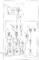
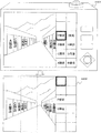
図1は、本発明の第1の実施形態の構成図である。
第1の実施形態に係る全体構成(システム101)は、大きく分けて撮影機102と地図サーバ120とから構成される。
FIG. 1 is a configuration diagram of a first embodiment of the present invention.
The overall configuration (system 101) according to the first embodiment is roughly composed of a photographing
撮影機102は、下に示す、撮影機102に関する補助情報を撮影機属性情報生成部121によって生成し、生成した補助情報を、通信部112によって、地図サーバへ送信する。撮影機102は、例えば、代表的にはデジタルスチルカメラ等が想定される。
The photographing
そして、撮影機102は、位置情報取得部103と、撮影方向取得部106と、フィルタ情報取得部111と、撮影範囲情報取得部122と、撮影機属性情報生成部121と、通信部112と、表示情報抽出部113と、撮影部114と、画像処理部115と、重複表示処理部116と、表示部117とから構成される。
The photographing
まず、位置情報取得部103は、撮影機の位置情報を取得する位置情報検知部104とその位置情報を出力する位置情報出力部105で構成される。位置情報取得部103は、撮影機102の位置を測定、出力する装置である。
First, the position
なお、位置情報検知部104が位置情報を検出する方法としては、代表的には、GPS(Global Postioning System)を用いるのが望ましい。しかし、必ずしも、位置情報検知部104による位置情報の取得に関しては、GPSの利用に限定されるものではなく、GPSと加速度センサ、方位センサを用いることで、GPSが使えない場所での位置を測定する技術の適応が可能であり、この構成によっても同等の効果を有する。
Note that, as a method for the position
また、位置情報検知部104が位置情報を検出する方法は、次に説明する方法であってもよい。すなわち、例えば観光地など多くのユーザが撮影を行う場所においては、あらかじめ位置情報を看板等に記載し、ユーザが手動で位置情報を取得することも可能である。これによって、GPSの位置情報が取得できない場合でも位置情報を取得することが可能である。また、これによって情報の測定誤差が小さくなる効果も期待できる。また、位置情報をQRコードにして看板に表示しておき、撮影機がこのQRコードを撮影することで位置情報を読み込むことも可能である。これによって、ユーザが位置情報を手動で入力する必要が無くなり、便利性が向上し、位置情報の入力間違いもなくなる。また、位置情報付きのQRコードを生成しなくても、無線LANや短距離無線などの無線基地局から位置情報に関する情報をブロードキャストし、撮影機が通信部112によって位置情報を取得する構成にしても、GPSと同等の効果を得ることができる。また、位置情報取得用の通信部と、通信部112(図1)は別の通信部にしてもよい。これは位置情報取得用の無線通信は短距離しか通信できない通信方式を利用することによって、より位置情報の取得精度を高めるためである。
Further, the method for detecting position information by the position
また、位置情報取得部103は、撮影機102と別の装置であってもよい。例えば携帯電話の位置情報測定機能を利用し、携帯電話から撮影機へ位置情報を短距離通信で送信する構成にしても良い。これによって、撮影機が新たに位置情報を取得するセンサを持つ必要が無くなり、撮影機の小型化、軽量化の効果が期待できる。
Further, the position
次に、撮影方向取得部106は、撮影機102のレンズが向いている方向を示す方向情報を取得する撮影方向検知部107と、撮影方向情報を出力する撮影方向出力部108とから構成される。撮影方向取得部106は、撮影機の方向情報を検出・出力する装置である。撮影方向を検出する方法として、例えば電子コンパスの利用が可能である。
Next, the shooting
次に、撮影範囲情報取得部122は、撮影機が撮影した範囲の情報(範囲情報)を取得するものである。範囲情報とは、撮影機102が撮影を行う撮影範囲を示すもので、例えば「10度〜270度」等という情報を取得することが望ましいが、必ずしもこれに限定されるものではなく、レンズのズーム情報とカメラの広角情報等でもよい。また、撮影機102がズーム機能等を使っており、撮影機102が撮影可能な機能を限定している場合には、撮影機102が撮影可能な最大の撮影範囲情報を取得しても良い。これは、撮影機102がランドマーク情報を取得した場合に、スイッチの切り替えやズーム量の変更によって撮影範囲が変わった時にもスムーズにランドマーク情報を表示するためである。
Next, the shooting range
なお、撮影機102が測定した位置情報と撮影方向情報等、ランドマーク情報を抽出するために撮影機102が取得した情報を総称して撮影機属性情報と呼ぶ。
Note that information acquired by the
次に、撮影機属性情報生成部121を説明する。位置情報取得部103、撮影方向取得部106、撮影範囲情報取得部122で作成された情報は、撮影機属性情報生成部121でヘッダなどが付加されたパケットとして(撮影機属性情報と呼ぶ)、通信部112(図1)が備える送信部から、地図サーバ120へ送信される。つまり、撮影機属性情報生成部121は、作成された各情報を取得して、取得された情報を、撮影機属性情報として地図サーバ120に送信する。
Next, the photographing machine attribute
なお、地図サーバ120のアドレスはあらかじめ撮影機102のメモリに登録しておくことが望ましいが、ユーザの登録によって変更可能にしても良い。これによって、例えば地図サーバ120のアドレスが変わった場合にも新しい地図サーバ120へ上記撮影機属性情報を送信することが可能となる。また、新たに別の地図サーバ120がサービスを開始した場合にもユーザのシステム移行がスムーズになる。
The address of the
次に、通信部112は、無線通信を介して、位置情報取得部103が取得した位置情報と、撮影方向取得部106が取得した撮影方向情報とを、地図サーバ120へ送信する。
Next, the
なお、通信部112は、無線LANを用いることが望ましいが、必ずしもこれに限定されることはなく、携帯電話やPHS、WiMAX(Worldwide Interoperability for Microwave Access)等の基地局通信を用いてもよいし、別の通信装置へ一旦撮影機属性情報を送信し、別の通信装置が地図サーバ120へ撮影機属性情報を送信する構成にしても良い。例えば、撮影機102は(撮影方向取得部106は)、携帯電話へ、無線LANや、UWBやZigBee等の短距離通信を用いて撮影機属性情報を送信し、携帯電話が、地図サーバ120へ、当該携帯電話に送信された撮影機属性情報を送信する構成が可能である。撮影機102が短距離通信で別の通信装置へデータを送り、別の通信装置が地図サーバ120へ撮影機属性情報を送信することによって、まず撮影機102の通信部112を小さくすることが可能である。また撮影機102の撮影機属性情報送信の電力を小さくすることができるため、撮影機102の利用可能時間を長くすることが可能である。
The
また、このような通信部112を有する撮影機102は、地図サーバ120との通信が電波環境の悪化などによって不可能になった場合は、位置情報と撮影情報を撮影機102のメモリに一時的に保存し、地図サーバ120との通信が可能になった後、地図サーバ120に対して保存した位置情報と撮影情報を通信部112によって送信し、送信によって得られたランドマーク情報を、撮影した画像のヘッダに付与しても良いし、地図サーバ120との通信が可能な別の機器(例えば、携帯電話)に近接通信により位置情報と撮影情報を送信し、他の機器によって地図サーバ120からのランドマーク情報の取得を行っても良い。
In addition, the
次に、地図サーバ120は、地図データベース118とランドマーク情報抽出部119からなる。
Next, the
まず、地図データベース118は、ランドマークに関する情報(ランドマーク情報)を位置情報と共に保持している。地図データベース118は、ランドマークのID・ランドマーク名称・緯度・経度・住所・電話番号・属性名称・階層順位・優先度等から構成されるランドマーク情報を格納する。ランドマーク情報に含まれる階層順位とは、複数のランドマーク情報を階層的に管理するためのもので、例えば、ビルのランドマーク情報とそのビルに入居する店舗のランドマーク情報が、同じ緯度・経度を持ち、ビルランドマークの階層順位を店舗ランドマークの階層順位よりも高く設定しておくことで、ビルとその中の店舗のランドマークを階層的に格納することができる。さらにランドマーク情報は、地図データベースに保存されるすべてのデータや属性、メタデータを含むものとする。代表的にはAビル、B寺院、C山といった建物や構造物の名前、飲食店、レジャー施設などの属性情報、飲食店のURL情報やクーポン情報、地図サーバを経由して得られるユーザが作成したコンテンツや、メタデータ等が挙げられるが必ずしもこれに限定されない。例えば、地図サーバと連携したソーシャルネットワークサービス(SNS)に含まれるユーザが作成した日記や、画像、映像、メタデータなどのコンテンツ情報もランドマーク情報と呼ぶ。
First, the
次に、ランドマーク情報抽出部119は、撮影機102から取得した撮影機属性情報をもとに、地図データベース118から撮影機102が撮影した画像に含まれるランドマーク情報と、その画像の周辺のランドマーク情報を抽出し、撮影機102へ送信する。ランドマーク情報抽出部119が周辺のランドマーク情報を送信することによって、ユーザが撮影機102をパンニングやズーミングした場合にも、過去に送信されたそれら周辺のランドマーク情報が撮影機102に用いられて、待ち時間無くランドマーク情報を表示することが可能となる。
Next, the landmark
なお、地図サーバ120が送信するランドマーク情報は、建物の名前など主要なもののみとし、URLやメタデータ等の情報はさらに撮影機102側からリクエストがあった場合に再度送信するか、予め撮影機102が送信して欲しいランドマーク情報の種類を指定しておくことが望ましい。これによって、ランドマーク情報抽出部119が地図データベース118から抽出するデータの量が減るため、抽出速度が速くなる効果が期待できる。また、地図サーバ120が撮影機102へ送信するランドマーク情報のデータサイズも小さくなるため、撮影機102がランドマーク情報を取得するまでの待ち時間が短くなる効果も期待できる。
It should be noted that the landmark information transmitted by the
次に、撮影機102の通信部112における受信部は、地図サーバ120から受信したランドマーク情報を表示情報抽出部113へ送信する。
Next, the reception unit in the
次に、フィルタ情報取得部111は、地図サーバ120から取得したランドマーク情報から、ユーザが求めるランドマーク情報のみを表示するためのフィルタリングに関する情報を検知するフィルタ情報検知部109と、当該フィルタ情報検知部109が検知した前記情報を送信するフィルタ情報出力部110から構成される。
Next, the filter
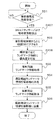
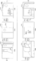
図2は、フィルタ情報検知部109の詳細を示す図である。
フィルタ情報検知部109は、表示解像度情報検知部201と、ユーザカテゴリ検知部202から構成され、これらの検知情報の組み合わせによってフィルタリングを行う。
FIG. 2 is a diagram illustrating details of the filter
The filter
まず、表示解像度情報検知部201は、撮影機102が撮影した画像情報とランドマーク情報を重複表示させる表示部117(図1)の解像度情報である。なお、表示解像度情報検知部201は、解像度情報を記憶するものであってもよい。
First, the display resolution
次に、ユーザ選択カテゴリ検知部202は、ユーザによる表示ランドマークのカテゴリ情報を検出するものである。ここで、ユーザによる表示ランドマークのカテゴリの一例を挙げる。ランドマークのカテゴリとしては、都市や地域名、レストランやカフェ、居酒屋に代表される飲食店、宿泊施設、地図サーバのコミュニティが作成したカテゴリ、スーパーやコンビニ、映画やDVDのレンタル、薬局や銀行ショッピングモールや百貨店などに代表されるショッピングやサービスに関するカテゴリ、空港や駅、ガソリンスタンドなどに代表される交通に関するカテゴリ。山や川の名前に代表される地勢に関するカテゴリ。寺社仏閣、温泉などに代表される観光地に関するカテゴリ、公園や学校、病院、図書館、郵便局などの施設カテゴリ、交通情報を表示する交通情報カテゴリなどが挙げられるが必ずしもこれに限定されるものではない。
Next, the user selection
他方、表示情報抽出部113(図1)は、フィルタ情報取得部111から取得したフィルタリング情報を元に、ランドマーク情報をフィルタリングする。具体的なフィルタリング方法に関しては後述する。フィルタリングしたランドマーク情報は、表示情報抽出部113により、重複表示処理部116へ送られる。
On the other hand, the display information extraction unit 113 (FIG. 1) filters the landmark information based on the filtering information acquired from the filter
撮影機102は、景観を撮影部114によって取得し、画像処理部115で画像処理を行った後、景観データを重複表示処理部へ送信する。
The photographing
次に、重複表示処理部116では、画像処理部115で取得した景観データに表示情報抽出部113で抽出したランドマーク情報をオーバレイ表示する処理を行う。なお、重複表示処理部116は、ユーザ操作などによって重複表示をしない場合には、ランドマーク情報を重複表示することなく、画像処理部115の画像データを表示部117へ送信する。
Next, the overlapping
次に、表示部117は、撮影情報とランドマーク情報の重複した表示を行う。なお、表示部117は、ボタンや、タッチパネル機能が搭載されていて、ユーザ操作を受け付けることによって、より詳細なランドマーク情報を表示させるなどの処理機能を持たせることも可能である。
Next, the
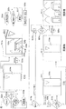
図3は、撮影機102が地図サーバ120へ送信するデータのフォーマットの一例を示す図である。
FIG. 3 is a diagram illustrating an example of a format of data transmitted from the photographing
撮影機102が地図サーバ120に送信するデータには、図3に示されるように、測位時刻と、撮影した位置情報を示す緯度情報と経緯情報、撮影方向を示す真北に対する進行方向、撮影範囲情報、さらに撮影機102のID情報を付加する。
As shown in FIG. 3, the data transmitted from the photographing
なお、撮影機102のID情報は、地図サーバ120にどの撮影機102がアクセスしたかを認識するために使う。撮影機102が一意に認識できるIDであればよい。無線通信装置のMACアドレスなどでも同等の効果を得ることが可能である。また、撮影機102のIDは必ずしも1台の撮影機102に1つである必要は無い。例えば、複数のユーザが撮影機102を使う場合には、ユーザ毎にIDを作成しても良い。
The ID information of the
なお、ここに、送信されるデータのデータフォーマットは、必ずしもこれに限定されるものではない。特に位置情報の精度情報を向上させるために、GPSのクオリティ、受信することができたGPS衛星の数、ディファレンシャルGPS(DGPS)のエイジ、DPS基準局のIDなどをデータフォーマットに付加して、DGPSからの補正計算によって位置情報の精度を向上させることが可能である。 Here, the data format of the data to be transmitted is not necessarily limited to this. In particular, in order to improve the accuracy information of the position information, the GPS format, the number of GPS satellites that could be received, the age of the differential GPS (DGPS), the ID of the DPS reference station, etc. are added to the data format. It is possible to improve the accuracy of the position information by the correction calculation.
ここで、撮影機102のモードを説明する。撮影機102は、画像撮影を行うための通常撮影モードと、ランドマークを画面表示しながら画像撮影や周辺情報の取得を行うためのランドマーク表示撮影モードと、撮影した画像を画面で再生するための再生モードとを備えており、ユーザは撮影機102の操作インタフェースを介して任意のモードに設定することができる。
Here, the mode of the photographing
そして、ランドマーク表示撮影モードでは、ユーザが撮影機102を撮影対象に向けることで、撮影対象と撮影対象に対応するランドマーク情報を画像として画面に表示する。以下では、撮影機102が、ランドマーク表示撮影モードにおいて、撮影対象のランドマーク情報を取得する処理について説明する。
In the landmark display shooting mode, when the user points the
図4は、撮影機102が風景を撮影し、撮影機属性情報を地図サーバ120へ送信するまでの一連のフローチャートである。
FIG. 4 is a series of flowcharts until the
まず、ユーザにより、SW等によって、ランドマーク表示モードへの切り替えが行われると(ステップ401)、撮影機102は、ランドマーク表示モードへ遷移する(ステップ402)。撮影機102の撮影機属性情報生成部121(図1)は、撮影機属性情報を作成し(ステップ404)、この情報を地図サーバ120へ送信する(405)。
First, when the user switches to the landmark display mode by SW or the like (step 401), the photographing
なお、ここで、撮影機102の変形例を説明する。撮影機属性情報には、撮影機102の位置情報と、撮影方向に関する情報が含まれるが、これらの位置情報検知部104と撮影方向検知部107を、撮影装置本体(撮影機102)には設けず、撮影装置本体(撮影機102)とは別の装置に分離する構成でもよい。例えば、位置情報検知部104と撮影方向検知部107を備えた携帯電話で取得した位置情報と撮影方向のすべてもしくはいずれかを、撮影装置(撮影機102)の受信部(図1に示される通信部112を参照)で受信するという構成にしても良い。これによって、撮影機102は、短距離無線の通信装置を備えることで、その携帯電話から位置情報と撮影方向情報の両方もしくはいずれか一方を取得することが可能となるため、位置情報や撮影方向を検出するセンサ等の検知部を備えないために、撮影機102小型化が可能になるというメリットを有している。
Here, a modified example of the photographing
なお、ここで、ステップ405で撮影機102により行われる撮影機属性情報の送信の処理の詳しい内容について説明する。撮影機102は、地図サーバ120のネットワークアドレスを用いて、ネットワークアドレスにより示されるサーバに対して送信を行うことにより、地図サーバ120に送信を行う。そして、撮影機102は、地図サーバ120のネットワークアドレス(URL)として、撮影装置が装置設定情報として記憶領域に格納しているものを使用する。なお、この、格納される、地図サーバ120のアドレスは、ユーザが撮影装置の操作インタフェースを用いて任意のアドレスに変更できるようにしてもよい。
Here, detailed contents of the process of transmitting the camera attribute information performed by the
図5は、地図サーバ120が撮影機属性情報を受信し、撮影機102へランドマーク情報を送信するまでの一連のフローチャートである。
FIG. 5 is a series of flowcharts until the
地図サーバ120は、まず撮影機属性情報を受信したかどうかのチェックを行う(ステップ501)。撮影機属性情報を受信した後、地図サーバ120は、撮影機属性情報を解析し、地図データベース(地図DB)118へアクセスし(ステップ502)、撮影機102が撮影している景観に含まれるランドマーク情報(撮影範囲ランドマーク情報)を取得する(ステップ503)。地図サーバ120は、取得した撮影範囲ランドマーク情報を、撮影機102に送信する(ステップ504)。撮影範囲ランドマーク情報を撮影機102に送信した後、地図サーバ120は、撮影範囲周辺のランドマーク情報(撮影周辺ランドマーク情報)を取得し(ステップ505)、取得した撮影周辺ランドマーク情報を撮影機102へ送信する(ステップ506)。
The
続けて、地図サーバ120が、ステップ505で、先にステップ503で受信した撮影機属性情報を元にランドマーク情報を取得する方法について詳しい説明を行う。
Next, a detailed description will be given of a method in which the
図6は、撮影機属性情報を元に地図サーバ120がランドマーク情報を取得するエリアを示した図である。
FIG. 6 is a diagram showing an area where the
地図サーバ120は、撮影機102から送信された位置情報・方向情報を含む撮影機属性情報を受信し(図5のステップ501)、地図サーバ120のランドマーク情報抽出部119が、撮影機属性情報から得られる撮影範囲(図6において破線により示される撮影機の撮影範囲)より少し大きい範囲(撮影範囲ランドマーク情報取得範囲)の地図上のランドマーク情報を地図データベース118から抽出する(ステップ503)。
The
ここで、この撮影範囲とは、図6に示されるように、扇型の範囲であり、扇型の中心角の位置は撮影装置の位置であり、扇型の中心角の二等分線、つまり図6における上方向きの矢印線は、撮影機102が撮影を行う撮影方向と一致し、扇型の中心角は、撮影機属性情報に含まれる撮影範囲情報である。
Here, as shown in FIG. 6, the photographing range is a fan-shaped range, the position of the fan-shaped central angle is the position of the photographing device, and the bisector of the fan-shaped central angle, That is, the upward arrow line in FIG. 6 coincides with the photographing direction in which the photographing
また、撮影範囲ランドマーク情報取得範囲がなす扇形の半径、すなわち撮影範囲ランドマーク情報取得範囲の円弧の撮影機102からの距離に関しては、地図サーバ120が保持する所定値を用いる。
Further, a predetermined value held by the
なお、この所定値は、撮影機102から半径を5kmの範囲と設定することが望ましい。これは、撮影機102が地上1.5mの高さにあると仮定した場合のおおよその水平線までの距離である。なお、この所定値に関しては必ずしも5kmである必要はない。例えば撮影機102の位置情報と地図サーバ120に保存された標高情報より撮影機102の位置の高度を計算し、さらにそれに撮影機102の地上からの高さを1.5m等と仮定し、撮影機102の高度から計算される地平線までの距離を、地図サーバ120が有する上記ランドマーク情報抽出部119が抽出するランドマークの半径、つまり上記所定値とすることで、さらに精度良くランドマーク情報の範囲を限定することが可能となる。
The predetermined value is desirably set within a range of 5 km from the photographing
図7は、地図サーバ120が撮影機102へ送信するランドマーク情報の範囲の一例を示す図である。
FIG. 7 is a diagram illustrating an example of a range of landmark information that the
先の図6に示された撮影周辺ランドマーク情報取得範囲は、当該範囲の内側の撮影範囲ランドマーク情報取得範囲よりさらに扇形の角度を広げた範囲とする。図7に示すように、地図サーバ120は、撮影機102に、まず撮影範囲ランドマーク情報を送信した後(図5のステップ504)、撮影周辺ランドマーク情報取得範囲のランドマーク情報を取得し(ステップ505)、撮影機102へ送信する(ステップ506)。これは、まず、撮影範囲のランドマーク情報を作成するまでの待ち時間を短くすると共に、撮影機102が撮影範囲周辺のランドマーク情報を保持しておくことによって、撮影機がパンニングした場合に、再度地図サーバ120のランドマーク情報取得処理を待つことなく、ランドマーク情報を迅速に表示することが可能となる効果を生む。
The shooting peripheral landmark information acquisition range shown in FIG. 6 is a range in which the fan-shaped angle is further expanded from the shooting range landmark information acquisition range inside the range. As shown in FIG. 7, the
なお、図7では、一例として、撮影周辺ランドマーク情報取得範囲の扇形の角度が、約250度〜約110度の範囲での250−110=140度であり、撮影範囲ランドマーク情報取得範囲の扇形の角度が、約237度〜約155度の範囲での237−155=82度(<140度)であり、撮影範囲の扇形の角度(撮影画角)が、約210度〜約155度の範囲での、210−155=55度(<82度<140度)である例を示している。 In FIG. 7, as an example, the fan-shaped angle of the shooting peripheral landmark information acquisition range is 250−110 = 140 degrees in the range of about 250 degrees to about 110 degrees, and the shooting range landmark information acquisition range is The fan-shaped angle is 237-155 = 82 degrees (<140 degrees) in the range of about 237 degrees to about 155 degrees, and the fan-shaped angle (shooting field angle) of the shooting range is about 210 degrees to about 155 degrees. In this example, 210-155 = 55 degrees (<82 degrees <140 degrees).
ランドマーク情報抽出部119(図1)は、地図データベース118からランドマーク情報を抽出し、これら抽出した複数のランドマーク情報を、撮影機属性情報を送信してきた撮影装置に対して送信する。
The landmark information extraction unit 119 (FIG. 1) extracts landmark information from the
撮影装置の受信部(図1に示される通信部112を参照)は、地図サーバ120から送信されたランドマーク情報を受信し、表示部117が、受信部が受信したランドマーク情報の全部または一部を、撮影部114および画像処理部115で取得した撮影画像とともに、撮影機102が有する画面に表示する。撮影装置は、ランドマーク情報の全部を表示するランドマーク全表示モードか、一部を表示するランドマーク一部表示モードかを、ランドマーク表示設定情報として、撮影機102が有する記憶部の記憶領域に格納しておく。
A receiving unit (see the
なお、このようなランドマーク表示設定は、ユーザが撮影装置の操作インタフェースを用いて任意のランドマーク表示モードに変更でき、つまり、撮影機102は、操作インタフェースの操作を受け付けて、格納されるランドマーク表示設定情報を変更するようにしてもよい。
Note that such landmark display setting can be changed to any landmark display mode by the user using the operation interface of the photographing apparatus. That is, the photographing
図8は、撮影機102がランドマーク情報を表示し、表示部117に重複表示する処理のフローチャートである。
FIG. 8 is a flowchart of a process in which the photographing
撮影機102が行う撮影範囲ランドマーク情報に対する動作と、撮影周辺ランドマーク情報に対する動作とは、基本的に同じであるため、ここでは一括してこれらをランドマーク情報と呼ぶことにし、以下からこのランドマーク情報のフィルタリング方法について説明を行う。
Since the operation for the shooting range landmark information performed by the
撮影機102は、地図サーバ120から、ランドマーク情報を受信すると(ステップ801:YES)、その受信したランドマーク情報の中で、表示するランドマーク情報をフィルタリングするためのフィルタリング情報を取得する(ステップ803)。フィルタリング情報に関しては、後で詳細に記述する。撮影機102は、フィルタリング情報を元に、受信したランドマーク情報をフィルタリングし、表示部117により、撮影された画像に写った景観に重複してランドマーク情報を表示する。
When receiving the landmark information from the map server 120 (step 801: YES), the photographing
撮影機102は、地図サーバ120からランドマーク情報を取得したかどうかをチェックする(801)。そして、撮影機102は、ランドマーク情報を受信したならば、次に受信したすべてのランドマークを表示するかどうかの判定処理を行う。撮影機102は、全てのランドマークを表示するか否かを特定する全ランドマークの表示設定を記憶部に格納しており、この表示設定により全て表示することが特定される場合(ステップ802:YES)、受信したすべてのランドマークを表示することを判定し、特定されない場合(ステップ802:NO)、全てのランドマークを表示せず、一部のみを表示することを判定する。
The photographing
なお、このような、全ランドマークの表示設定は、ユーザによる設定が望ましい。例えば、ランドマーク表示ボタンをユーザが切り替えることで、撮影機102が、全ランドマーク表示と、フィルタリングしたランドマークのみを表示させるモードを切り替えるものとしても良い。
It should be noted that such display settings for all landmarks are preferably set by the user. For example, when the user switches the landmark display button, the photographing
全ランドマークを表示する場合(ステップ802:YES)、撮影機102は、当該撮影機102のレンズから取得した撮影風景と、地図サーバ120から取得したランドマーク情報を、重複表示処理部116によって、重複表示させる(ステップ805)。
When all the landmarks are displayed (step 802: YES), the photographing
他方、全ランドマークを表示させない場合(ステップ802:NO)、撮影機102は、フィルタリングしたランドマーク情報のみを表示する(ステップ803〜805)。表示情報抽出部113は、まずフィルタ情報取得部111より、ランドマーク情報のフィルタリングに関する情報を取得し(ステップ803)、取得したフィルタリング情報によって、表示するランドマーク情報を抽出する(ステップ804)。重複表示処理部116は、抽出されたランドマーク情報と、画像処理部115より得られた風景画像を重複表示させる(ステップ805)。
On the other hand, when not displaying all the landmarks (step 802: NO), the photographing
以下、フィルタリング方法について説明する。
撮影機102が、ランドマーク一部表示モードに設定されている場合は、表示情報抽出部113が、地図サーバ120から受信したランドマーク情報の中から表示するランドマーク情報を抽出する。撮影機102は、当該撮影機102の各部から取得した撮影機属性情報をもとにしてフィルタリングを行う。より具体的には、撮影機102は、撮影機102のズームの大きさに応じて、ランドマーク情報を表示する領域を、撮影位置からの距離で限定し、つまり、その距離に対応する対応領域に限定し、さらに、表示するランドマークの名前を、表示可能な解像度に応じて、変更する。
Hereinafter, the filtering method will be described.
When the photographing
地図サーバ120には、前述したようにランドマーク情報が階層化されて保存されている。より詳しくは、地図サーバ120には、層が深くなる(階層が大きくなる)ほど、より詳細なランドマーク情報が保存されている。例えば、上位の階層にはビル街の名前が保存され、その下位の層にはビルの名前が保存され、さらにその下位の層にはビルに入っているテナントの名前が保存されている。つまり、地図サーバ120は、ランドマーク情報と共に、全体である上位のランドマークの上位のランドマーク情報と、当該上位のランドマークがなす全体に含まれる一部分である、下位のランドマークの下位のランドマーク情報との間の階層関係を記憶し、これにより、記憶されるランドマーク情報は階層化されている。
The
撮影機102は、地図サーバ120から送信されたランドマーク情報を表示するために、撮影機102が撮影した空間を撮影機102からの距離によって複数の領域に分割する。そして、撮影機102は、一つの領域あたりに表示可能な最大ランドマーク数を撮影機の解像度情報によって決定する。撮影機102は、解像度が大きければ、表示可能な最大ランドマーク数を大きくする。
In order to display the landmark information transmitted from the
図9は、ランドマーク情報を区切る空間の名称を示す図である。
地図サーバ120が有する地図データベース118(図1)が保持するランドマーク情報には、そのランドマーク情報のランドマークの位置が、図9に示される各空間(メッシュ領域)のうち、いずれの空間に属するかを示す位置情報が含まれる。
FIG. 9 is a diagram illustrating the names of spaces that delimit landmark information.
In the landmark information held in the map database 118 (FIG. 1) of the
撮影機102の近傍は、図9に示されるように、撮影機102からの距離が予め定められた範囲か否かに応じて、複数の領域に分割される。図9では、一例として、撮影機102の近傍が、3つの領域に分割される例を示している。そして、これら、分割された各領域は、撮影機102からの距離に応じて近距離を第1領域、中距離を第2領域、遠距離を第3領域とする。
As shown in FIG. 9, the vicinity of the photographing
また、撮影機102の近傍は、図9に示されるように、撮影機102の撮影方向からの角度が予め定められた範囲か否かに応じて、複数の領域に分割され、撮影範囲は、水平方向のこれら各領域に分割される。以後、これら、分割された各領域を、レンジと呼ぶ。そして、撮影方向付近の範囲を第1レンジ、より広角の範囲を第2レンジ、さらに広角の範囲を第3レンジとする。
Further, as shown in FIG. 9, the vicinity of the photographing
以下の説明では、領域やレンジによって分割された空間の一つをメッシュ領域と呼ぶ。
撮影機102がズームを行うと、撮影される撮影範囲のレンジの幅も小さくなる。撮影機102のズーム比を大きくすると、撮影範囲の角度が小さくなる。撮影機102は、これに合わせて、フィルタリングで用いるレンジの角度を小さくする。例えば撮影範囲を3つのレンジに分解すると設定しておけば、ズーム比が大きくなれば、用いるレンジの幅が小さくなり、ズーム比が大きくなれば、用いるレンジの幅も相対的に広くなる。
In the following description, one of the spaces divided by regions and ranges is called a mesh region.
When the photographing
なお、領域やレンジ、階層の数に関しては必ずしもここに記載された数に限定されるものではない。なお、撮影機102には、レンジ分割のために、多軸のセンサを持たすことが望ましい。つまり、撮影機102が通常の撮影を行っている時には、水平方向の偏差を検出する電子コンパスによって、撮影機102が向いている方向を検出し、撮影機102が垂直方向に長い画像を撮影するために90度傾けられて利用される場合には、通常撮影の向きで垂直方向、すなわち90度傾けられた撮影機102で水平方向の偏差を検出する電子コンパスに切り替え、この電子コンパスで、撮影機102の向いている方向や、レンジの区切りを設定することが望ましい。これによって、撮影機102を90度回転させた場合にも、正しくレンジの設定と、撮影方向の検出が可能となる。
Note that the number of regions, ranges, and layers is not necessarily limited to the numbers described here. Note that it is desirable that the photographing
撮影機102は、一つのメッシュ領域に表示するランドマーク数の上限を、当該撮影機102が撮影を行う解像度より決定する。解像度が大きくなれば一領域あたり表示可能なランドマーク数は大きくなる。
The photographing
なお、以下では、一例として、1つのメッシュ領域あたり表示する上限のランドマーク数(メッシュ領域あたり最大表示ランドマーク数)が2である場合を説明する。なお、以下では、メッシュ領域のことを、表記の便宜上のため、単に領域と略称する場合がある。 In the following, a case where the upper limit number of landmarks displayed per mesh area (maximum number of displayed landmarks per mesh area) is 2 will be described as an example. In the following, the mesh area may be simply abbreviated as an area for convenience of description.
なお、これらの点については、あとで更に詳しく説明する。
図10は、各階層あたりのランドマーク数と、実際に表示するランドマークの階層を示す図である。
These points will be described in more detail later.
FIG. 10 is a diagram illustrating the number of landmarks per layer and the levels of landmarks that are actually displayed.
地図サーバ120が有する地図データベース118(図1)が保持するランドマーク情報には、そのランドマーク情報のランドマークが属する階層を示す階層情報が含まれる。この階層情報は、当該ランドマーク以外の他のランドマークの当該階層よりも小さければ、当該ランドマークが、その、他のランドマークよりも下位であることを示し、同じであれば同位であることを示し、大きければ下位であることを示す。この階層情報は、先述した記憶される階層関係である。
The landmark information held in the map database 118 (FIG. 1) of the
そして、撮影機102は、表示情報抽出部113によって、地図サーバ120から取得されるランドマーク情報のうちから、当該各ランドマーク情報に含まれる階層情報により定まる一部のランドマーク情報を抽出し、つまり選択して、各ランドマーク情報のうちで、抽出したランドマーク情報を表示させる。
Then, the photographing
例えば、図10では、一例として、第3領域の第1レンジに位置することが、その位置に対応するバツ印によって示されるランドマーク情報は、第1階層に属し、第1階層を示す階層情報を含み、図10における第2層の欄における、第3領域の第2レンジのなかのバツ印により示される、上記の第1階層のランドマーク情報とは別のランドマーク情報は、第2階層のランドマーク情報に属する例を示している。 For example, in FIG. 10, as an example, landmark information that is located in the first range of the third area and indicated by a cross mark corresponding to the position belongs to the first hierarchy, and represents the first hierarchy. Landmark information different from the above-mentioned first layer landmark information indicated by a cross in the second range of the third region in the second layer column in FIG. An example belonging to the landmark information is shown.
撮影機102は、一つのメッシュ領域当り表示可能なランドマーク数を超えない範囲で、もっとも階層が深いランドマークのランドマーク情報までを表示する。
The photographing
そして、撮影機102は、最上位、つまり図10における第1層の階層のランドマーク数が、メッシュ領域あたり最大表示ランドマーク数を超えている場合は、中心部に近いレンジのメッシュ領域から、メッシュ領域当り最大表示ランドマーク数を超えない範囲で、ランドマークを表示する。
Then, when the number of landmarks in the top layer, that is, the first layer in FIG. 10 exceeds the maximum number of displayed landmarks per mesh area, the photographing
今、領域当り最大表示ランドマーク数を2とする。第3領域は、第1層での合計のランドマーク数は1、第2層での合計のランドマーク数は2、第3層での合計のランドマーク数は4であるため、第3領域では、領域当り最大表示ランドマーク数2と同じ合計のランドマーク数であった、第2層のランドマークまでの各階層のランドマーク情報が表示される。また、第2領域を説明すると、第3層のランドマーク数は1、第4層のランドマーク数は2であるため、第2領域には第4層のランドマークを表示させる。また、第1領域の第1層のランドマーク数はすでに最大表示ランドマーク数2を超えている。この場合、撮影機102は、レンジによって、表示するランドマークをフィルタリングする。すなわち、第1領域−第1レンジのランドマーク数は2、第1領域−第2レンジのランドマーク数は4であるため、この場合には第1領域−第1レンジのランドマークが表示される。
Now, assume that the maximum number of display landmarks per area is two. In the third area, the total number of landmarks in the first layer is 1, the total number of landmarks in the second layer is 2, and the total number of landmarks in the third layer is 4. Then, the landmark information of each layer up to the landmark of the second layer, which has the same total number of landmarks as the maximum number of displayed
なお、表示する領域を撮影機102のズーム量によって抽出しても良い。
図11は、ズーム量と表示領域の対応表の一例を示す図である。
Note that the area to be displayed may be extracted based on the zoom amount of the photographing
FIG. 11 is a diagram illustrating an example of a correspondence table between zoom amounts and display areas.
撮影機102は、ズーム量によって抽出を行う場合には、以下で説明するようにして、図11によって説明される処理をして、抽出をする。
When performing extraction based on the zoom amount, the photographing
撮影機102の近傍は、撮影位置からの距離によって、3つの領域に分割され、撮影装置が光学ズーム(物理的なレンズ駆動によるズーム)で1倍〜10倍のズーム撮影機能を有するとして、撮影機102は、1倍〜3倍ズームの場合には第1領域(近距離領域)、3倍〜6倍ズームの場合は第2領域(中距離領域)、6倍〜10倍の場合は第3領域(遠距離領域)のランドマーク情報を、それぞれ抽出する。すなわち、ズームが小さい場合は撮影位置に近いランドマークが撮影機102によって抽出され、ズームが大きい場合は撮影位置から遠いランドマークが撮影機102によって抽出される。これによって、ユーザが知りたい領域のランドマーク情報のみを表示させることが可能になるため、ユーザの利便性が向上する。
The vicinity of the photographing
なお、ランドマーク階層順位の選び方としては、第2階層以上の階層順位のランドマークを抽出する方法や、ランドマーク数が最小となる階層順位のランドマークを抽出する方法、ユーザがあらかじめ設定した階層順位のランドマークを抽出する方法がある。また、ランドマーク表示上限数に最も近くなるように自動的に階層順位を選択してもよい。 In addition, as a method of selecting the landmark hierarchy order, a method of extracting landmarks having a hierarchy order higher than the second hierarchy, a method of extracting landmarks having a hierarchy order that minimizes the number of landmarks, a hierarchy set in advance by the user There is a method for extracting landmarks of ranking. Further, the hierarchical order may be automatically selected so as to be closest to the landmark display upper limit number.
また、表示領域は必ずしもズーム量によって決定する構成に限定されるものではなく、ズーム量ではなく撮影機102の焦点距離に応じて表示領域を変更しても良い。すなわち、図10で説明すると、撮影機102の焦点距離が近い場合には第1領域に存在する被写体のランドマークを表示し、撮影機102の焦点距離が遠い場合には第3領域に存在する被写体のランドマークを表示する。撮影機102にオートフォーカス機能がついていれば、ユーザは撮影機102のズームボタンの操作を行うことなく、ユーザが知りたい被写体のランドマーク情報を取得することが可能となる。
Further, the display area is not necessarily limited to the configuration determined by the zoom amount, and the display area may be changed according to the focal length of the photographing
また、人間の顔を認識した場合にはその顔にフォーカスを合わせる顔認識フォーカス機能が撮影機102についている場合には、撮影機102は、顔認識フォーカス機能が動作していない場合には、焦点距離によってランドマークを表示する領域を決定し、顔認識フォーカス機能が動作すると、撮影機102のズーム機能によってランドマークの表示領域を決定するモードに移行する機能を搭載しても良い。これによって、顔認識フォーカス機能が搭載された撮影機102では、景観に歩行者の顔が写ると、焦点距離が変わり、表示領域が急に変化することが無くなり、ランドマーク表示領域の安定化に繋がる。
In addition, when a face recognition focus function for focusing on a human face is provided in the
また、撮影機102は、撮影距離および階層順位を用いて抽出したランドマーク情報が所定のランドマーク表示上限数を超えている場合、1つまたは複数の優先度を選択することによってランドマーク情報を絞り込む。例えば、ランドマーク優先度の選び方としては、所定の優先度以上のランドマークを抽出する方法や、優先度が最も高いランドマークを抽出する方法、ユーザがあらかじめ設定した優先度のランドマークを抽出する方法がある。また、ランドマーク表示上限数に最も近くなるように自動的に優先度を選択してもよい。
In addition, when the landmark information extracted using the photographing distance and the hierarchical order exceeds a predetermined landmark display upper limit number, the photographing
なお、ランドマーク情報を表示する領域を水平方向に分割することで、撮影機102は、そのように分割された分割領域に基づいて、ランドマークを抽出してもよい。例えば、水平方向の撮影画角が90度である場合に、左側30度分を左領域、中央30度分を中央領域、右側30度分を右領域とし、所定の領域に含まれるランドマーク情報を抽出する。水平方向分割領域の中から所定の領域を設定する方法としては、中央領域に固定設定する方法や、撮影装置の操作インタフェースを用いてユーザが設定する方法などがある。特に、ユーザが領域を設定する場合については、撮影装置の設定情報としてユーザが撮影前に水平方向分割領域を設定してもよいし、表示部117によるランドマークおよび撮影画像の表示後に、水平方向分割領域を選択し再設定してもよい。
Note that, by dividing the area for displaying the landmark information in the horizontal direction, the photographing
重複表示処理部は、全てのランドマーク情報(ランドマーク全表示モード時)もしくは表示情報抽出部113によって抽出されたランドマーク情報(ランドマーク一部表示モード時)と撮影画像を重ね合わせて、画面に表示する表示画像を作成する。以下に代表的なランドマーク情報表示方法を示す。 The overlapping display processing unit superimposes all the landmark information (in the all landmarks display mode) or the landmark information extracted by the display information extracting unit 113 (in the partial landmark display mode) and the captured image, and displays the screen. Create a display image to be displayed on the screen. A typical landmark information display method is shown below.
図37は、ランドマーク表示画面の一例を示す図である。
なお、図37の上部に示された、山の稜線や、A服店やC服店などが面する道路などの画像が表示された、画像表示する領域のなかに示される、「W旅館」や「Yホテル」などの各文字は、それぞれ、単に、説明の便宜上から付された文字であり、撮影機102が表示させる文字ではない。
FIG. 37 is a diagram illustrating an example of a landmark display screen.
It should be noted that “W Ryokan” shown in the image display area in which the image of the mountain ridgeline, the road facing the A clothing store, the C clothing store, and the like shown in the upper part of FIG. 37 is displayed. Each character such as “Y Hotel” is simply a character added for convenience of explanation, and is not a character displayed by the photographing
一方で、図37の下部に示された、升目状の矩形領域は、撮影機102が、ランドマーク情報を表示させるランドマーク表示部分であり、このランドマーク表示部分に示される「C服店」、「A服店」などの各文字は、撮影機102が、ランドマーク情報として、ランドマーク表示部分に表示させる文字である。
On the other hand, the square-shaped rectangular area shown in the lower part of FIG. 37 is a landmark display portion on which the photographing
撮影機102は、上部の、画像表示する領域と、画像表示する領域の下部に設けられた、ランドマーク表示部分とを備える。ランドマーク表示部分は、撮影されている被写体が存在するメッシュ領域の水平方向の同じ位置にランドマーク名を表示する。これによって、ユーザにとって被写体とそれに対応するランドマークの対応が把握しやすくなるという効果が期待できる。また、ランドマーク表示部分は、撮影機からの距離が遠い領域のランドマークを表示領域の上部に、撮影機からの距離が近い領域のランドマークを表示領域の下部にそれぞれ表示する。また、ランドマーク表示部分は、同じ領域のランドマークに対しても、撮影機からの距離が遠い被写体は表示部の上部に、撮影機からの距離が近い被写体は表示部の下部に表示する。ユーザは、被写体の領域によって、表示がされる表示部分を変えることによって、撮影機と被写体の大まかな距離を知ることができると共に、撮影機と被写体の相対的な遠近を視覚的に知ることができるという効果が期待できる。
The photographing
さらに、撮影機が、撮影機の方向に最も近く、かつ最も手前のランドマーク名をマーキングや強調表示する。マーキングの例としては、カーソルボタンを前述のランドマーク名にあわせて置くことが望ましい。表示部の中心で、かつ手前のランドマークの情報をユーザがアクセスする頻度が高くなるため、ランドマークの詳細表示の際にユーザのカーソル移動の処理が不要になるという効果が期待できる。 Further, the photographing machine marks or highlights the landmark name closest to the direction of the photographing machine and closest to the photographing machine. As an example of marking, it is desirable to place a cursor button in accordance with the landmark name described above. Since the frequency at which the user accesses the landmark information in the center of the display unit and in the foreground becomes high, an effect that the user's cursor movement process is not required when displaying the detailed landmarks can be expected.
また、ランドマーク名の横に、撮影機から、対応する被写体までの直線距離や、被写体までアクセスするために必要な経路距離を表示させても良い。被写体までの距離を知ることによって、ユーザは被写体へアクセスする移動手段の検討をすることが可能となる。 Further, a linear distance from the camera to the corresponding subject or a route distance necessary for accessing the subject may be displayed next to the landmark name. By knowing the distance to the subject, the user can consider moving means for accessing the subject.
また、画面下部ではなく、画面上部や画面左端、画面右端にランドマーク表示領域を設けてもよい。画面左端もしくは画面右端に表示領域を設ける場合は、撮影位置から被写体への方向に応じて該当する被写体のランドマーク名称を表示領域内で左右に並べるとともに、撮影位置から被写体までの距離に応じて該当する被写体のランドマーク名称を表示領域内で上下に並べて表示する。 Further, a landmark display area may be provided at the upper part of the screen, the left end of the screen, or the right end of the screen instead of the lower part of the screen. When a display area is provided at the left or right edge of the screen, the corresponding subject landmark names are arranged side by side in the display area according to the direction from the shooting position to the subject, and according to the distance from the shooting position to the subject. The landmark names of the corresponding subjects are displayed side by side in the display area.
図38は、画面右端にランドマークを表示した場合の画面表示の一例を示す図である。図38では、撮影位置に近いランドマークから順に、画面下部から画面上部にかけて並べて表示している図である。 FIG. 38 is a diagram showing an example of a screen display when a landmark is displayed at the right end of the screen. In FIG. 38, the landmarks close to the shooting position are displayed in order from the bottom of the screen to the top of the screen.
これによって、ランドマークの表示位置と、撮影機から被写体までの距離の相対的な対応がとることが可能になり、遠方の被写体など、肉眼ではどちらが遠方か分からないような被写体に対しても、どちらの被写体が遠いかという情報をユーザは視覚的に把握することが可能となる。また、ランドマークの水平方向の位置で分割して、ランドマークを複数列に分割しても良い。 This makes it possible to take a relative correspondence between the display position of the landmark and the distance from the camera to the subject.For subjects that are far away, such as far away subjects, The user can visually grasp which subject is far away. Alternatively, the landmark may be divided into a plurality of rows by dividing the landmark at a horizontal position.
図39は、ランドマークを2列に表示させた場合の表示部の一例を示す図である。ランドマークを複数列表示にすることによって、ランドマークの水平方向の位置の把握が容易になるというメリットがある。 FIG. 39 is a diagram illustrating an example of a display unit when landmarks are displayed in two rows. By displaying the landmarks in a plurality of rows, there is an advantage that it is easy to grasp the position of the landmark in the horizontal direction.
図40は、領域に対応する表示部分に、その領域のランドマークが表示された表示部の一例を示す図である。 FIG. 40 is a diagram illustrating an example of a display unit in which landmarks of a region are displayed on a display portion corresponding to the region.
図40のように、撮影機から遠方の第3領域に位置する被写体のランドマーク名は、表示部の右上部に、第2領域に位置する被写体のランドマーク名は表示部の右中部に、撮影機近傍の第1領域に位置する被写体のランドマークは、表示部の右下部に表示する構成にしても良い。これにより、ユーザはランドマークがどの領域に存在する被写体の情報を表示しているかを知ることが容易になるため、例えばビル街など多くのランドマークが存在する地域で使用する場合に、被写体とランドマークの対応を誤る可能性が低下する。 As shown in FIG. 40, the landmark name of the subject located in the third area far from the camera is in the upper right part of the display unit, and the landmark name of the subject located in the second area is in the middle right part of the display unit. The landmark of the subject located in the first area near the photographing device may be displayed on the lower right side of the display unit. This makes it easy for the user to know in which area the landmark is displaying information on the subject.For example, when using in an area where many landmarks exist, such as a building street, The possibility of mistaken landmarks is reduced.
ランドマーク情報の重複表示方法は、ユーザが、表示するランドマークのジャンルを設定することで、画面表示するランドマークをさらにフィルタリングする構成としてもよい。 The landmark information overlapping display method may be configured such that the user further filters the landmarks displayed on the screen by setting the genre of the landmarks to be displayed.
図41は、撮影装置の操作メニュー画面の一例を示す図である。
ユーザが撮影前に撮影装置の操作メニューを用いて、優先表示するランドマークのジャンルを選択しておけば、ユーザの嗜好に合致するランドマークを表示することができる。
FIG. 41 is a diagram illustrating an example of an operation menu screen of the photographing apparatus.
If the user selects the genre of the landmark to be preferentially displayed using the operation menu of the photographing apparatus before photographing, the landmark that matches the user's preference can be displayed.
図41の例では、優先表示を行うランドマークのジャンル設定において、「ファッション」・「レジャー」・「公共」・「交通」・「宿泊」・「飲食」・「人気スポット」・「その他」を選択可能なジャンルとして表示しているが、これらに限定されるものではない。また、前記ジャンル選択肢のうち、「人気スポット」については、撮影時におけるURLアクセス数が上位のランドマークを優先表示するものとしてもよいし、撮影機の画像に含まれるランドマークのHPの中で、検索サービスの検索ランキングの上位に位置するランドマークを表示しても良い。また、前記ジャンル選択肢のうち、「その他」を選択した場合には、ユーザが画面上に表示されるソフトウェアキーボード等を用いて任意のジャンルキーワードを入力し、そのジャンルキーワードをランドマーク情報内に含有するランドマークを優先表示するものとしてもよい。 In the example of FIG. 41, in the genre setting of landmarks for priority display, "fashion", "leisure", "public", "transportation", "accommodation", "food", "popular spots", "other" Although displayed as selectable genres, it is not limited to these. Among the genre options, “popular spot” may display a landmark having a higher URL access number at the time of shooting, or may be included in the landmark HP included in the image of the camera. A landmark positioned higher in the search ranking of the search service may be displayed. When “Other” is selected from among the genre options, the user inputs an arbitrary genre keyword using a software keyboard displayed on the screen, and the genre keyword is included in the landmark information. The landmarks to be displayed may be preferentially displayed.
図42は、被写体の詳細情報表示方法の一例を示す図である。
ランドマークの中から、ユーザが撮影装置の操作インタフェースを用いて任意のランドマークを一つ選択できるようにし、詳細なランドマーク情報を表示する。例えば、ランドマーク表示領域内にランドマーク選択のためのカーソルを表示し、多くのデジタルスチルカメラが搭載しているような十字(上下左右方向)キーを用いて、カーソルを移動させてランドマークの選択を行う方法がある。ランドマークが選択されると、ランドマーク詳細情報表示領域を画面中に表示し、この表示領域内にID・ランドマーク名称・ランドマークURL・緯度・経度・住所・電話番号・属性名称・階層順位・優先度を表示する。
FIG. 42 is a diagram illustrating an example of a method for displaying detailed information about a subject.
The user can select one arbitrary landmark from among the landmarks using the operation interface of the photographing apparatus, and the detailed landmark information is displayed. For example, a cursor for selecting a landmark is displayed in the landmark display area, and the cursor is moved by using the cross (up / down / left / right) keys as many digital still cameras are equipped with. There is a way to make a selection. When a landmark is selected, a landmark detailed information display area is displayed on the screen, and an ID, a landmark name, a landmark URL, a latitude, a longitude, an address, a telephone number, an attribute name, and a hierarchical order are displayed in this display area. -Display priority.
なお、ランドマークの選択に関して、撮影装置の画面をユーザの指による接触を検知可能なタッチ式画面とし、このタッチ式画面に表示されたランドマークに指で触れることで選択する構成としてもよい。画面をタッチ式にすることによって、ランドマーク選択のためのカーソルキーが不要になるため、撮影機の小型化や、表示画面の大型化が可能となるという利点がある。 In addition, regarding the selection of the landmark, the screen of the photographing apparatus may be a touch screen that can detect contact with the user's finger, and the landmark displayed on the touch screen may be selected by touching with the finger. By making the screen a touch type, there is no need for a cursor key for selecting a landmark, and there is an advantage that the photographing machine can be downsized and the display screen can be enlarged.
選択したランドマークがランドマークURLの情報を持ち、ランドマーク詳細情報表示領域にランドマークURLを表示する場合は、ユーザが撮影装置の操作インタフェースを用いてURLが示すホームページを画面に表示する。ランドマーク詳細情報表示領域にランドマークURLを表示している状態で、ユーザが撮影装置の操作キーにより、ランドマークURLを選択すると、撮影装置に内蔵されたウェブブラウザが起動し、選択されたURLが示すホームページをインターネットから読み込んで、画面にホームページを表示する。 When the selected landmark has landmark URL information and the landmark URL is displayed in the landmark detailed information display area, the user displays the home page indicated by the URL on the screen using the operation interface of the photographing apparatus. When the landmark URL is displayed in the landmark detailed information display area, when the user selects the landmark URL by using the operation key of the photographing apparatus, a web browser built in the photographing apparatus is activated and the selected URL is selected. The homepage indicated by is read from the Internet, and the homepage is displayed on the screen.
なお、撮影装置にウェブブラウザを搭載することが困難な場合は、選択されたランドマークURLを携帯電話等のウェブブラウザを搭載した外部機器に送信するようにしてもよい。 If it is difficult to install a web browser in the photographing apparatus, the selected landmark URL may be transmitted to an external device equipped with a web browser such as a mobile phone.
なお、撮影機は、ランドマークURLにアクセスする際に、撮影機固有のIDを送信する構成も可能である。これによって、撮影機にアクセスされたHPはどの撮影機がHPにアクセスしたかが分かるため、例えば飲食店などで、撮影機からのアクセスに対して通常のPC等によるインターネットアクセスとは違ったクーポン情報等を表示することが可能となる。撮影機からのアクセスは、撮影機を持つユーザが被写体の近辺にいる可能性が高いことを示すため、より効果的な集客のPRが可能であるためである。その他にも、撮影機が被写体の近傍にいる可能性が高いことを利用して、撮影機からアクセスしたユーザにのみタイムサービスの広告ページを表示することも可能であり、これによって、ユーザの利便性とサービス提供会社の効率よい宣伝が実現する。 Note that the camera can be configured to transmit an ID unique to the camera when accessing the landmark URL. This makes it possible for the HP accessed to the camera to know which camera has accessed the HP. For example, in a restaurant, the coupon is different from the Internet access by a normal PC or the like for access from the camera. Information or the like can be displayed. This is because the access from the photographing machine indicates that there is a high possibility that the user who has the photographing machine is in the vicinity of the subject, and therefore, more effective PR of customers can be performed. In addition, it is possible to display the advertisement page of the time service only to the user who has accessed from the camera using the fact that the camera is likely to be in the vicinity of the subject. And efficient promotion of service providers.
なお、図42では、ランドマークの中から、ユーザが撮影装置の操作インタフェースを用いて任意のランドマークを一つ選択できるようにし、詳細なランドマーク情報を表示する方法を示したが、表示されるランドマーク数が所定値以下であれば詳細情報付きのランドマークを表示しても良い。これによって、ユーザが、ランドマークを選択し、詳細表示ボタンを押すなどの詳細表示を行う処理を省略することが可能となる。 FIG. 42 shows a method of displaying detailed landmark information by allowing the user to select one arbitrary landmark from the landmarks using the operation interface of the photographing apparatus. If the number of landmarks is less than or equal to a predetermined value, a landmark with detailed information may be displayed. As a result, it is possible to omit a process of performing detailed display such as a user selecting a landmark and pressing a detailed display button.
また、詳細表示を行うのではなく、表示されるランドマークが所定値以下であれば、そのランドマークのURLへアクセスし、URL先の情報を表示させても良い。詳細表示された内容よりも、URL先の情報量が多いため、この機能によってユーザはより被写体の詳細な情報を知ることが可能となる。 Further, instead of performing detailed display, if the displayed landmark is equal to or less than a predetermined value, the URL of the landmark may be accessed to display the URL destination information. Since the amount of information at the URL destination is larger than the content displayed in detail, this function allows the user to know more detailed information about the subject.
図43は、撮影機が、ズーム操作に基づいてURLにアクセスする変形例を示す図である。 FIG. 43 is a diagram illustrating a modification in which the photographing device accesses the URL based on the zoom operation.
なお、図43に示すように、撮影装置のズーム操作によって画面中に1つのランドマークのみが最大ズーム倍率で表示されている場合に、ユーザがさらにズームイン操作を行うと、ウェブブラウザが起動し、画面に表示されているランドマークのURLに自動的にアクセスする構成としてもよい。このようにすることによって、ユーザはズーム操作のみで、ランドマークのURLにスムーズにアクセスすることができるようになる。画面中に拡大表示されているランドマークがURL情報を持っていない場合は、ウェブブラウザを起動しないようにすることが望ましい。 As shown in FIG. 43, when only one landmark is displayed at the maximum zoom magnification on the screen by the zoom operation of the photographing apparatus, when the user further zooms in, the web browser is started, It may be configured to automatically access the landmark URL displayed on the screen. By doing so, the user can smoothly access the landmark URL only by zooming. When the landmark displayed enlarged on the screen does not have URL information, it is desirable not to start the web browser.
図46は、本発明に係る、重複表示方法の別構成を示す図である。
画面下部にランドマーク情報に含まれるランドマークの名称を表示する表示領域を設ける。撮影されている被写体と被写体に該当するランドマーク名称が画面の表示領域内で水平方向に一致するように表示する。加えて、撮影位置から被写体までの距離に応じて該当する被写体のランドマーク名称を表示領域内で上下に並べて表示する。例えば、画面下部に2のランドマーク表示を行う場合、1行目、2行目の順に、ランドマーク表示された被写体までの距離が大きくなる。
FIG. 46 is a diagram showing another configuration of the overlapping display method according to the present invention.
A display area for displaying the name of the landmark included in the landmark information is provided at the bottom of the screen. The photographed subject and the landmark name corresponding to the subject are displayed so as to coincide with each other in the horizontal direction within the display area of the screen. In addition, according to the distance from the shooting position to the subject, the corresponding landmark names of the subject are displayed side by side in the display area. For example, when the
表示画面4601にズームが一倍の時のランドマーク表示方法を、表示画面4602にズームが5倍の時のランドマーク表示方法の一例を示す。撮影機は、ズームが小さいときは近傍のランドマークを表示し、ズームが大きくなるときには遠方のランドマークを表示する。
A
ズーム量に応じて、ランドマークの表示領域を変えることによって、例えば、ユーザはズームによって遠方の地域の名称を知りたい場合には、ユーザはズーム機能によって遠方のランドマークを表示させることによって近傍のランドマークを表示せず、遠方のランドマーク情報のみを表示させることが可能となる。 By changing the display area of the landmark according to the zoom amount, for example, when the user wants to know the name of a distant area by zooming, the user can display a nearby landmark by displaying a distant landmark by the zoom function. Only landmark information in the distance can be displayed without displaying the landmark.
なお、表示するランドマーク名称が所定の字数を超えている場合は、撮影機が所定字数を超えた分の名称を省略して表示してもよいし、名称を縮小して表示してもよい。これによって、被写体の名称が長い場合にも、被写体とランドマークの水平方向の対応関係を保持したまま、ランドマークと被写体の重複表示が可能になる。 If the landmark name to be displayed exceeds a predetermined number of characters, the camera may display the name that exceeds the predetermined number of characters, or may display the name in a reduced size. . Accordingly, even when the name of the subject is long, the landmark and the subject can be displayed in an overlapping manner while maintaining the horizontal correspondence between the subject and the landmark.
また、情報地図サーバ(地図サーバ)が予め、名称が長いランドマークには短い簡易名称を付加し、簡易情報と正式な名称を撮影機へ送信することも可能である。これによって撮影機での名称が長いランドマーク表示には、簡易名称を用い、さらにユーザ操作によって、詳細情報を表示することを可能にする。 It is also possible for the information map server (map server) to add a short simple name to a landmark having a long name in advance and transmit the simple information and the official name to the photographing machine. As a result, a simple name is used for displaying a landmark having a long name on the photographing machine, and further detailed information can be displayed by a user operation.
計算機能力の高い地図サーバが簡易名称と正式名称を保持し、これを撮影機へ送信することによって、撮影機でのランドマーク表示のレスポンスを上げることが可能となり、ユーザの利便性が向上する。 A map server having a high calculation function holds a simple name and a formal name, and transmits them to the photographing machine. This makes it possible to improve the response of the landmark display on the photographing machine, thereby improving user convenience.
また、地図サーバにランドマークを登録する時に長い正式名称のランドマークと、簡易名称のランドマーク名を登録しておくことによって、ユーザにとって分かりやすい簡易表記でランドマーク名を表示することが可能となる。 In addition, by registering a long official landmark and a simple landmark name when registering a landmark on the map server, the landmark name can be displayed in a simple notation that is easy for the user to understand. Become.
なお、撮影機が地図サーバへ送信する撮影機属性情報に撮影機に表示可能なランドマーク名の長さを計算するための情報を送信し、この情報に基づき地図サーバは、簡易表示の名称を決定する構成にしても良い。表示可能なランドマーク名の長さを知るために必要な情報としては解像度情報が望ましい。解像度が高い撮影機にランドマークを表示する場合には、比較的長い名称にランドマーク名の簡略化を行い、解像度が低い撮影機にランドマークを表示する場合には、短い名称にランドマーク名の簡略化を行う。これによって、表示装置の解像度に最適な長さでランドマークを表示させることが可能となる。 Information for calculating the length of the landmark name that can be displayed on the camera is transmitted to the camera attribute information transmitted from the camera to the map server. Based on this information, the map server displays the name of the simple display. You may make it the structure to determine. Resolution information is desirable as information necessary to know the length of a landmark name that can be displayed. When displaying a landmark on a camera with a high resolution, simplify the landmark name on a relatively long name, and when displaying a landmark on a camera with a low resolution, display the landmark name on a short name. Simplification. As a result, the landmark can be displayed with a length optimal for the resolution of the display device.
なお、表示対象となるランドマークの位置を水平方向に限定することで、画面表示するランドマークをさらにフィルタリングする構成としてもよい。例えば、図44に示すように、画面中央付近に画面上部から下部にわたる矩形枠を表示し、この矩形枠内に対応する位置にあるランドマークの中から、ズームが小さいときは近傍のランドマークを表示し、ズームが大きくなるときには遠方のランドマークを表示する。このような構成にすることで、ズームに応じたフィルタリングのみを利用する場合よりもランドマークを絞り込むことができる。また、ランドマークを限定する矩形枠の大きさは、撮影装置(撮影機)の操作インタフェースを介して、ユーザが撮影機のズームボタンやカーソルキーで任意の幅に変更できるような機構を設けることや、あらかじめ用意された複数の矩形幅の中から選択できるようにすることが望ましい。これによって、ユーザが知りたい範囲のランドマーク数のみを表示させることが可能となる。また、表示範囲を狭めることでより詳細な情報を表示させる構成にしても良い。 Note that the landmarks to be displayed on the screen may be further filtered by limiting the positions of the landmarks to be displayed in the horizontal direction. For example, as shown in FIG. 44, a rectangular frame extending from the upper part to the lower part of the screen is displayed near the center of the screen, and when the zoom is small, the nearby landmarks are selected from the landmarks corresponding to the rectangular frame. When the zoom is increased, a distant landmark is displayed. With such a configuration, landmarks can be narrowed down compared to the case of using only filtering according to zoom. Also, the size of the rectangular frame that limits the landmark should be provided with a mechanism that allows the user to change it to any width using the zoom button or the cursor key of the photographing device via the operation interface of the photographing device (photographing device). It is also desirable to be able to select from a plurality of rectangular widths prepared in advance. As a result, it is possible to display only the number of landmarks in a range that the user wants to know. Further, it may be configured to display more detailed information by narrowing the display range.
また、撮影機の表示部にタッチパネル機能を持たせ、ユーザが撮影機へ2本の指をのせた幅に応じてランドマークの表示範囲をユーザが変更できる機能を付けても良い。これによりランドマーク表示範囲を中心部だけでなく、表示部の右端の一部分をユーザが選択することが可能となり、ランドマーク表示範囲の選択幅が広がるというメリットがある。 Further, the display unit of the photographing machine may be provided with a touch panel function, and a function that allows the user to change the display range of the landmark according to the width of the user placing two fingers on the photographing machine. As a result, the user can select not only the center of the landmark display range but also a part of the right end of the display unit, and there is an advantage that the selection range of the landmark display range is widened.
図47は、撮影機が、ランドマーク情報に含まれる高さ情報に応じて、フィルタリングをする変形例を示す図である。 FIG. 47 is a diagram illustrating a modification in which the imaging device performs filtering according to the height information included in the landmark information.
ランドマーク情報に含まれる高さ情報に応じて、画面表示するランドマークをさらにフィルタリングする構成としてもよい。例えば、図47に示すように、ランドマークが密集している地点を撮影する場合、前記のズームに応じたフィルタリングによって絞り込まれたランドマークの中で、高さ情報が大きなランドマークから順に選んで表示する。高さの大きいランドマークは他のランドマークに全部が隠されてしまうことが少ないと考えられる。したがって、高さ情報が大きなランドマークから順に選んで表示することによって、ユーザの視界(撮影画面)に入っていないランドマークの表示を回避することができる。 The landmark displayed on the screen may be further filtered according to the height information included in the landmark information. For example, as shown in FIG. 47, when shooting a spot where landmarks are dense, among the landmarks narrowed down by the filtering according to the zoom, height information is selected in descending order from the landmark. indicate. It is considered that a landmark with a large height is less likely to be completely hidden by other landmarks. Therefore, by selecting and displaying in order from landmarks having the highest height information, it is possible to avoid the display of landmarks that are not in the user's field of view (shooting screen).
なお、本実施例では撮影位置から被写体までの距離に応じて該当する被写体のランドマーク名称を表示領域内で上下に並べて表示するとしたが、撮影装置(撮影機)の操作インタフェースでのユーザ操作に応じて、ランドマーク表示領域の表示・非表示を切り替えてもよい。例えば、ユーザが任意の操作を行った直後にランドマーク表示領域を表示し、表示開始から所定時間経過後にランドマーク表示領域を非表示にする構成がある。このようにすれば、ユーザが必要な場合にのみランドマークを表示することができる。 In this embodiment, the landmark names of the corresponding subject are displayed side by side in the display area in accordance with the distance from the shooting position to the subject. However, the user interface on the operation interface of the shooting device (shooter) can be used. Accordingly, the display / non-display of the landmark display area may be switched. For example, there is a configuration in which a landmark display area is displayed immediately after a user performs an arbitrary operation, and the landmark display area is hidden after a predetermined time has elapsed since the start of display. In this way, landmarks can be displayed only when the user needs them.
図48は、撮影機が、ランドマーク周辺の地図情報を表示する変形例を示す図である。
撮影機は、図48に示すように、特定のランドマーク情報の詳細表示を行った場合に、詳細表示を行ったランドマーク周辺の地図情報を表示してもよい。これによってランドマーク周辺の地理を見ることが可能となる。
FIG. 48 is a diagram illustrating a modification in which the photographing machine displays map information around the landmark.
As shown in FIG. 48, when the detailed display of the specific landmark information is performed, the photographing machine may display the map information around the landmark on which the detailed display is performed. This makes it possible to see the geography around the landmark.
図49は、撮影機が、撮影機の位置情報をあわせて表示する変形例を示す図である。
撮影機は、図49のように、撮影機の位置情報もあわせて表示させても良い。これによって、現在地から詳細表示させたランドマークへの物理的アクセス経路と相対的な位置関係が容易に把握することができるというメリットがある。
FIG. 49 is a diagram illustrating a modification in which the photographing machine displays the position information of the photographing machine together.
The camera may display the position information of the camera together as shown in FIG. As a result, there is an advantage that it is possible to easily grasp the relative positional relationship with the physical access route to the landmark displayed in detail from the current location.
図44は、撮影機が帯状のエリアを表示させる変形例を示す図である。
撮影機は、ランドマーク表示範囲を絞りたい場合は、撮影画像の表示中に、撮影機のズームボタンの操作によって、図44のように帯状のエリアを表示させ、この帯状のエリアのランドマーク情報のみを表示させる構成にしても良い。帯状のエリアは、ズームボタンの操作によって表示部の中心部から左右対称の範囲となるようにしても良いし、さらに、帯状のエリアをズームボタンで決定し、さらにカーソルキーなどで帯状のエリアを左右に動かすことでランドマーク情報を表示させるエリアを決定する構成にしても良い。通常ズームボタンは画像撮影時に表示領域の拡大・縮小に用いるボタンであるため、ズームボタンの操作によって表示領域を変更させる構成にすることによって、ランドマーク情報の表示領域を拡大・縮小する際にユーザは直感的に操作を行うことが可能となる。
FIG. 44 is a diagram illustrating a modification example in which a photographing machine displays a band-shaped area.
When the photographing machine wants to narrow down the landmark display range, a band-like area is displayed as shown in FIG. 44 by operating the zoom button of the photographing machine while the photographed image is being displayed, and landmark information of this belt-like area is displayed. Only the display may be displayed. The band-shaped area may be a symmetrical range from the center of the display unit by operating the zoom button. Further, the band-shaped area is determined with the zoom button, and the band-shaped area is further determined with a cursor key or the like. The area for displaying the landmark information may be determined by moving left and right. Since the normal zoom button is used to enlarge / reduce the display area during image capture, the user can zoom in / out the landmark information display area by changing the display area by operating the zoom button. Can be operated intuitively.
図12は、撮影機1201等に係る変形例を示す図である。
図12を用いてユーザ操作とインターネットアクセスによるランドマークの詳細情報表示について説明を行う。地図サーバ1204が持つデータベースにはランドマーク特定のIDと、URL情報を保持している。地図サーバ1204は、撮影機1201へ送信するランドマーク情報には、URL情報は付加しない。
FIG. 12 is a diagram illustrating a modification example related to the photographing
The detailed information display of landmarks by user operation and Internet access will be described with reference to FIG. The database possessed by the
撮影機1201には、データ1202の様に、ランドマークのID(LM−ID)、名称等URL以外のデータが格納されている(1)。今、LM−IDがJ−126574であるランドマークの名前が富士ホテルだとする。
The photographing
ユーザ操作によって、富士ホテルのURL情報へアクセスする動作を説明する。
ユーザが重複表示された富士ホテルのクリック等により、富士ホテルのURL情報取得の要求を行うと、撮影機1201は、地図サーバ1204へ特定のLM−ID情報を送信する(2)。つまりこの場合富士ホテルのLM−ID「J−126574」を送信する。地図サーバ1204では、LM−IDの詳細情報とカウンタが保持されており、特定のLM−IDの詳細情報の送信要求が撮影機1201から地図サーバ1204に送信されると、この特定のLM−IDのURL情報を撮影機1201へ送信するとともに、アクセス数をカウントアップする(3)。アクセスカウンタをカウントアップ後に、地図サーバ1204は、撮影機1201へ送信されたIDのURL情報を送信する(4)。この場合には富士ホテルのIDを受信した地図サーバ1204は、富士ホテルのアクセスカウンタを増やし、富士ホテルのURL情報を撮影機1201へ送信する。撮影機1201は、地図サーバ1204よりURL情報を取得すると(5)、URLの宛先の第二サーバ1205へアクセスする(6)。第二サーバ1205は、こうしてアクセスがされると、撮影機1201へURL先の情報を送信する(7)。URL先の情報を取得した撮影機1201は、表示画面1203のように画面にURL先に記載された詳細情報を表示する(8)。
An operation for accessing the URL information of Fuji Hotel by user operation will be described.
When the user makes a request for acquiring Fuji Hotel URL information by, for example, clicking on a Fuji hotel displayed in duplicate, the
図12の構成によって、地図サーバ1204は、ユーザがURLにアクセスしたランドマーク情報を知ることができる。これによって、地図サーバ1204は、人気があるランドマークの情報を知ることが可能となると共に、撮影機1201のアクセス数をカウントすることで、撮影機1201がアクセスした被写体のURLを管理する者から課金をすることが可能となり、地図サーバ1204の管理者が経済的な効果を得られるというメリットもある。また、地図サーバ1204が撮影機1201へURL情報を送信するときに、ユーザがアクセス要求したランドマーク情報に関連する付加情報を撮影機1201へ送信することも可能である。
With the configuration of FIG. 12, the
図13は、撮影機1201等に係る変形例を示す図である。
また、撮影機1201によるURLアクセスは、図13に示す構成にしても良い。まず撮影機1201が特定のLM−IDの情報を地図サーバ1204へ送る(2)。地図サーバ1204はLM−IDのカウンタを増やし(3)、LM−IDに対応したURLにアクセスする(4)。第2のサーバ1205は、地図サーバ1204がアクセスする、LM−IDに対応したURL先の情報を地図サーバ1204へ送り返す(5)。地図サーバ1204は、URL先の情報と、付加情報を付けて撮影機1201へデータの送信を行う(6)。URL情報を入手した撮影機1201は、画面にURLの情報と付加情報を表示する(8)。この構成により、地図サーバ1204は、ユーザがアクセス要求したランドマーク情報に関連する付加情報を撮影機1201へ送信することが可能となる。
FIG. 13 is a diagram illustrating a modification example related to the photographing
Further, the URL access by the photographing
付加情報としては、アクセス要求されたランドマーク情報に関連する広告などが望ましいが、必ずしもこれに限定されるものではない。例えば、ランドマークが飲食店やホテルであった場合には、付加情報として、クーポンを表示することが可能である。 The additional information is preferably an advertisement related to the landmark information requested to be accessed, but is not necessarily limited thereto. For example, when the landmark is a restaurant or a hotel, a coupon can be displayed as additional information.
また、地図サーバ1204が他の撮影機1201のアクセス履歴を管理しておき、例えばあるユーザが富士ホテルにアクセスした場合に、他のユーザが富士ホテルをアクセスした前後にアクセスしたランドマーク情報を表示することも可能である。これによって、ユーザが次にアクセスしたいと考えるランドマーク情報を推薦することが可能である。
Also, the
撮影機1201がURLにアクセスする際には、地図サーバ1204を経由してアクセスさせる図13の形態により、地図サーバ1204は、撮影機1201のアクセス履歴を管理することが可能となる。これにより撮影機1201がアクセスした被写体のURLを管理する者から課金をすることが可能となり、地図サーバ1204の管理者が経済的な効果を得られるというメリットもある。また、付加情報として広告を載せる場合には、地図サーバ1204の管理者は、広告の依頼主からの課金を行うことが可能となり、経済的な効果を得られるというメリットもある。
When the
(第2の実施形態)
第2の実施形態に係る付加情報フィルタリングシステムは、デジタル画像を撮影する画像撮影装置と、前記デジタル画像と共に、当該デジタル画像に含まれる各オブジェクトにそれぞれ対応する複数の付加情報を表示する画像表示装置とを備え、前記画像撮影装置は、前記デジタル画像を撮影する撮影部と、前記撮影部で前記デジタル画像を撮影した撮影位置を取得する撮影位置取得部と、前記撮影部で前記デジタル画像を撮影した撮影方向を取得する撮影方向取得部と、前記撮影部で撮影した前記デジタル画像と、前記位置情報取得部で取得した撮影位置と、前記撮影方向取得部で取得した撮影方向とを出力する出力部を有し、前記画像表示装置は、出力された前記デジタル画像と前記撮影位置と前記撮影方向とを入力する入力部と、入力された前記撮影位置と前記撮影方向とに対応する、前記デジタル画像に含まれるオブジェクトにそれぞれ対応する前記複数の付加情報を取得する付加情報取得部と、前記付加情報取得部で取得した前記複数の付加情報から、表示する付加情報を選択する選択部と、入力された前記デジタル画像と共に、前記選択部で選択した付加情報を表示する表示部とを有することを特徴とする付加情報フィルタリングシステムである。
(Second Embodiment)
The additional information filtering system according to the second embodiment includes an image capturing device that captures a digital image, and an image display device that displays a plurality of additional information corresponding to each object included in the digital image together with the digital image. The image photographing device includes a photographing unit that photographs the digital image, a photographing position obtaining unit that obtains a photographing position where the digital image is photographed by the photographing unit, and the digital image is photographed by the photographing unit. An output for outputting the shooting direction acquisition unit for acquiring the shooting direction, the digital image shot by the shooting unit, the shooting position acquired by the position information acquisition unit, and the shooting direction acquired by the shooting direction acquisition unit The image display device includes an input unit that inputs the output digital image, the shooting position, and the shooting direction; An additional information acquisition unit that acquires the plurality of additional information corresponding to each of the objects included in the digital image corresponding to the captured shooting position and the shooting direction, and the plurality of additional information acquired by the additional information acquisition unit An additional information filtering system comprising: a selection unit that selects additional information to be displayed from additional information; and a display unit that displays additional information selected by the selection unit together with the input digital image. .
また、第2の実施形態に係る付加情報フィルタリングシステムは、デジタル画像を撮影する画像撮影装置と、前記デジタル画像と共に、付加情報を表示する画像表示装置と、前記デジタル画像に含まれる各オブジェクトの付加情報を前記画像表示装置に送信する付加情報提供サーバとを備え、前記画像撮影装置は、前記デジタル画像を撮影する撮影部と、前記撮影部で前記デジタル画像を撮影した撮影位置を取得する撮影位置取得部と、前記撮影部で前記デジタル画像を撮影した撮影方向を取得する撮影方向取得部と、前記撮影部で取得したデジタル画像と、前記位置情報取得部で取得した前記撮影位置と、前記撮影方位情報取得部で取得した前記撮影方向とを出力する出力部を有し、前記画像表示装置は、出力された前記デジタル画像と前記撮影位置と前記撮影方向とを入力する入力部と、入力された前記撮影位置と前記撮影方向とを前記付加情報提供サーバに送信して、当該前記付加情報提供サーバから、送信した前記撮影位置と前記撮影方向とに対応する前記デジタル画像に含まれる各オブジェクトに対応する複数の付加情報を取得する付加情報取得部と、前記付加情報取得部で取得した前記複数の付加情報から、表示する付加情報を選択する選択部と、入力された前記デジタル画像と共に、前記選択部で選択した付加情報を表示する表示部とを有し、前記付加情報提供サーバは、オブジェクトの付加情報を保持するデータベースと、送信された前記撮影位置と前記撮影方向とを受信する受信部と、受信された前記撮影位置と前記撮影方向とに対応する、前記デジタル画像に含まれる各オブジェクトに対応する前記複数の付加情報を前記データベースより抽出する付加情報抽出部と、抽出された前記付加情報を前記画像表示装置に送信する送信部とを有する付加情報フィルタリングシステムである。 Further, the additional information filtering system according to the second embodiment includes an image capturing device that captures a digital image, an image display device that displays additional information together with the digital image, and an addition of each object included in the digital image. An additional information providing server that transmits information to the image display device, wherein the image photographing device captures the digital image, and a photographing position that obtains a photographing position where the digital image is photographed by the photographing unit. An acquisition unit; a shooting direction acquisition unit that acquires a shooting direction in which the digital image was shot by the shooting unit; a digital image acquired by the shooting unit; the shooting position acquired by the position information acquisition unit; and the shooting An output unit that outputs the shooting direction acquired by the azimuth information acquisition unit, and the image display device An input unit for inputting a shooting position and the shooting direction; and the input shooting position and the shooting direction are transmitted to the additional information providing server, and the transmitted shooting position is transmitted from the additional information providing server; Additional information acquisition unit for acquiring a plurality of additional information corresponding to each object included in the digital image corresponding to the shooting direction, and additional information to be displayed from the plurality of additional information acquired by the additional information acquisition unit A display unit that displays additional information selected by the selection unit together with the input digital image, and the additional information providing server includes a database that holds additional information of an object, A receiver for receiving the transmitted shooting position and shooting direction; and the digital image corresponding to the received shooting position and shooting direction. Murrell is additional information filtering system and a transmission unit for transmitting the additional information extracting unit that a plurality of additional information extracted from the database, extracted the additional information to the image display device corresponding to each object.
図15〜16、図45、図17〜図21は、第2の実施形態に係る図である。
図15は、本発明の一実施例に係るシステム1501の構成図を示す図である。
15 to 16, FIG. 45, and FIGS. 17 to 21 are diagrams according to the second embodiment.
FIG. 15 is a diagram showing a configuration diagram of a
第2の実施形態に係るシステム1501は、大きく分けて、撮影機1502と表示機1550と地図サーバ120から構成される。
A
本実施例においては、撮影機1502で撮影された画像に、表示機1550でランドマーク情報を重複し、表示する。このような撮影機と表示機を分離した構成にすることによって、表示機を大型化することができるとともに、例えば自宅等に設置された表示機で、外出時に撮影した画像にランドマーク情報を合成して表示するといった使用方法が可能となる。
In the present embodiment, the landmark information is overlapped and displayed by the
図16は、第2の実施形態の利用方法の一例を示す図である。
撮影機1601は、撮影した画像情報と撮影属性情報とを可搬型外部メモリ1602を用いて表示機1603へ移動させる。表示機1603は、地図サーバ120よりランドマーク情報を取得し、重複表示を行う。表示機1550は、一般的に撮影機1502よりも高性能の処理プロセッサを持ち、また、インターネットへアクセスする手段を持っているため、この構成にすることによって、撮影機1502が地図サーバ120へアクセスする装置を当該撮影機1502に搭載する必要が無くなるため、撮影機1502の小型化が可能となる。また、重複表示された撮影画像を撮影機1502より大きい画面を持つ表示機1603で表示させることが可能となり、また、表示機1603の操作ボタンやリモコンによって表示項目などの設定が可能となるため、ユーザの利便性が向上する。
FIG. 16 is a diagram illustrating an example of a usage method according to the second embodiment.
The photographing
撮影機1502は、位置情報取得部103と、撮影方向取得部106と、撮影範囲情報取得部122と、撮影機属性情報生成部1521と、外部メモリ制御部1541と、撮影部1514と、画像処理部1515から構成される。
The camera 1502 includes a position
撮影機1502は、下に示す、当該撮影機1502に関する補助情報を撮影機属性情報生成部1521によって生成し、外部メモリ制御部1541によって、生成した撮影機属性情報を、撮影した画像とともに外部メモリ制御部1541が保持する可搬型外部メモリに記憶する。
The photographing machine 1502 generates auxiliary information related to the photographing machine 1502 shown below by the photographing machine attribute
撮影機1502は、代表的にはデジタルスチルカメラ等が想定され、外部メモリ制御部1541が保持する可搬型外部メモリは代表的には不揮発性メモリカード等が想定される。
The camera 1502 is typically assumed to be a digital still camera or the like, and the portable external memory held by the external
まず、位置情報取得部103は、撮影機1502の位置を測定、出力する装置である。
次に、位置情報取得部103は、第1の実施形態における図1の位置情報取得部103と同様の処理を行う。なお、撮影機が、無線LANや短距離無線などの通信部を備える構成とすることによって、位置情報付きのQRコードを生成しなくても、無線LANや短距離無線などの無線基地局からブロードキャストされる位置情報に関する情報を受信することができるので、GPSと同等の効果を得ることができる。
First, the position
Next, the position
次に、撮影方向取得部106は、撮影機1502の方向情報を検出し、検出した方向情報を出力する装置である。撮影方向取得部106は、第1の実施形態における図1の撮影方向取得部106と同様の処理を行う。
Next, the photographing
なお、これらの位置情報検知部104と撮影方向検知部107を、撮影機1502本体とは別の装置に分離する構成でもよい。例えば、位置情報検知部104と撮影方向検知部107とを備えた携帯電話で取得した位置情報と撮影方向のすべてもしくはいずれかを、撮影装置(撮影機1502)の受信部で受信するという構成にしても良い。これによって、携帯電話に位置情報を備えると共に、撮影機は短距離無線の通信装置を備えることで位置情報と撮影方向の両方もしくはいずれか一方を取得することが可能となるため、位置情報や撮影方向を検出するセンサを備えないために小型化が可能になるというメリットを有している。
The position
次に、撮影範囲情報取得部122は、撮影機1502が撮影した範囲の情報を取得するものである。撮影範囲情報取得部122は第1の実施形態における図1の撮影範囲情報取得部122と同様の処理を行う。
Next, the shooting range
そして、撮影機1502は、撮影機1502に備えられたシャッターの押下等を検知した際に、景観画像を撮影部1514によって取得し、画像処理部1515で、取得された景観画像の画像処理を行った後、外部メモリ制御部1541で、画像処理がされた後の画像データを、可搬型外部メモリに記憶する。この画像データの記憶時に、撮影機属性情報生成部1521は、位置情報取得部103、撮影方向取得部106、撮影範囲情報取得部122で作成された情報(撮影機属性情報と呼ぶ)を画像ヘッダデータとして、外部メモリ制御部1541に送る。外部メモリ制御部1541は、撮影機属性情報生成部1521から受け取った画像ヘッダデータを、可搬型外部メモリに格納された画像データのヘッダ部分に記憶する。
When the photographing device 1502 detects pressing of the shutter provided in the photographing device 1502 or the like, the photographing device 1502 acquires a landscape image by the photographing
なお、画像ヘッダのフォーマットとしては、例えばExif(Exchangeable image file format)規格が代表的であり、このような規格に沿った画像ヘッダを生成する構成が望ましい。 Note that the format of the image header is typically the Exif (Exchangeable image file format) standard, and a configuration that generates an image header in accordance with such a standard is desirable.
撮影機1502の外部メモリ制御部1541が保持する可搬型外部メモリは、撮影機1502および表示機1550に対して挿抜可能な構成とし、撮影機1502において撮影機属性情報および画像情報が記憶された可搬型外部メモリは、撮影機1502から抜き出して表示機1550に挿入される。表示機1550は、代表的にはテレビやPC等大型のディスプレイを持つ装置が想定される。
The portable external memory held by the external
また、表示機1550は、外部メモリ制御部1544と、フィルタ情報取得部111と、通信部1512と、表示情報抽出部1513と、重複表示処理部1516と、表示部1517から構成される。
The
ユーザが可搬型外部メモリに記憶された画像データの中から、閲覧したい画像データを検索および指定できるようにするため、表示機1550は、表示機1550が備える操作インタフェースを介してユーザの入力を受け付ける。
In order to allow the user to search and specify image data to be browsed from image data stored in the portable external memory, the
まず、外部メモリ制御部1544は、内部に保持する可搬型外部メモリに記憶された画像データの中から、ユーザが指定した画像データを重複表示処理部1516に送る。また、外部メモリ制御部1544は、このとき同時に、画像データとともに画像ヘッダデータとして記憶された撮影機属性情報を通信部1512に送る。
First, the external
次に、通信部1512では、通信部1512が送る撮影機属性情報に、通信用ヘッダ情報等を付加し、これを送信部から地図サーバ120へ送信する。地図サーバ120のアドレスはあらかじめ表示機の内部メモリに登録しておくことが望ましいが、ユーザの入力操作によって地図サーバ120のアドレスを変更可能にしても良い。これによって、例えば地図サーバ120のアドレスが変わった場合にも対応可能となる。また、新たに別の地図サーバ120がサービスを開始した場合にもユーザのシステム移行がスムーズになる。
Next, the
なお、通信部1512は、無線や有線LANを用いることが望ましいが必ずしもこれに限定されることはなく、携帯電話やPHS、WiMAX等の基地局通信を用いてもよいし、別の通信装置へ一旦撮影機属性情報を送信し、別の通信装置が地図サーバ120へ撮影機属性情報を送信する構成にしても良い。例えば、携帯電話へ無線LANや、UWBやZigBee等の短距離通信を用いて撮影機属性情報を送信し、携帯電話が地図サーバ120へ撮影機属性情報を送信する構成が可能である。表示機1550が短距離通信で別の通信装置へデータを送り、別の通信装置が用いて地図サーバ120へ撮影機属性情報を送信することによって、まず表示機1550の通信部1512を小さくすることが可能である。また表示機1550の撮影機属性情報送信の電力を小さくすることができる。
Note that the
また、地図サーバ120は、ランドマークに関する情報(ランドマーク情報)を表示機1550に送信する。地図サーバ120は、第1の実施形態における図1の地図サーバ120と同様の処理を行う。ただし、ランドマーク情報抽出部119は、撮影機1502から取得した撮影機属性情報をもとに、地図データベース118から撮影機1502が撮影した画像に含まれる全ランドマーク情報を送信する。
In addition, the
また、表示機1550の通信部1512における受信部は、地図サーバ120から受信したランドマーク情報を表示情報抽出部1513へ送信する。
In addition, the reception unit in the
次に、フィルタ情報取得部111は、地図サーバ120から取得したランドマークからユーザが求めるランドマーク情報のみを表示するためのフィルタリングに関する情報を検知するフィルタ情報検知部109と、検知した情報を送信するフィルタ情報出力部110とから構成される。フィルタ情報取得部111は、第1の実施形態における図1のフィルタ情報取得部111と同様の処理を行う。
Next, the filter
次に、フィルタ情報検知部109の詳細は、図1に示すように第1の実施形態で示した構成と同様である。
Next, the details of the filter
次に、表示情報抽出部1513は、フィルタ情報取得部111から取得したフィルタリング情報を元に、ランドマーク情報をフィルタリングする。具体的なフィルタリング方法に関しては、第1の実施形態で開示したフィルタリング方法と同様の処理方法を適用するものとする。フィルタリングしたランドマーク情報は重複表示処理部1516へ送られる。
Next, the display
なお、本実施例においては、表示機1550は、当該表示機1550にユーザからの画像選択指定操作が入力された場合に、撮影機属性情報を地図サーバ120へ送信し、地図サーバ120からランドマーク情報を受信する一連の処理を実行するとしたが、このようなランドマーク取得処理実行のタイミングに限定されるものではない。例えば、表示機1550は、可搬型外部メモリ挿入時や、ユーザからの操作が所定時間入力されなかった場合に、可搬型外部メモリ内の全画像データに対して、画像データのFAT(File Allocation Table)順や画像撮影時刻順等の順番でランドマーク取得処理をバックグラウンドで実行してもよい。ユーザ操作が行われる前や、アイドル時にランドマークを取得しておくことで、画像およびランドマークを重複表示する時にランドマーク取得のための待ち時間を大幅に減少させ、ユーザが表示機1550の操作を快適に行うことができる。
In this embodiment, the
次に、重複表示処理部1516では、外部メモリ制御部1544から取得した景観画像データに表示情報抽出部1513で抽出したランドマーク情報をオーバレイ表示する処理を行う。ユーザ操作などによって重複表示をしない場合には、ランドマーク情報を重複表示することなく、画像データをそのまま表示部1517へ送信する。
Next, the overlap
次に、表示部1517は、撮影情報とランドマーク情報の重複した表示を行う。
図45は、表示機1550と、リモコン4501とを示す図である。なお、図45に示すように表示機1550には本体操作ボタンや、操作リモコン4501等が搭載されていて、ユーザ操作を受け付けることによって、より詳細なランドマーク情報を表示させるなどの処理機能を持たせることも可能である。
Next, the
FIG. 45 shows a
表示機1550が地図サーバ120へ送信するデータのフォーマットは、第1の実施形態に一例として図3で示したデータフォーマットと同様である。
The format of data transmitted from the
表示機1550は、撮影した画像を画面で再生するための通常の再生モードと、ランドマークを画面表示しながら画像の閲覧やランドマークに関する詳細情報の取得を行うためのランドマーク表示モードを備えており、ユーザは表示機1550の操作インタフェースを介して任意のモードに設定することができる。ランドマーク表示モードでは、ユーザが表示機1550の操作インタフェースを介して、表示機1550が保持する可搬型外部メモリ内の画像データを選択することで、選択画像と選択画像に対応するランドマーク情報を画像として画面に表示する。以下では、続けて、ランドマーク表示モードにおいて、選択画像中に含まれる対ランドマーク情報を取得する処理について説明する。
The
図17は、表示機1550が景観画像データを再生し、撮影機属性情報を地図サーバ120へ送信するまでの一連のフローチャートである。
FIG. 17 is a series of flowcharts until the
表示機1550は、まずSW等によって、ランドマーク表示モードへの切り替えが行われると(401)ランドマーク表示モードへ遷移する(402)。すると、表示機1550の通信部1512は、撮影機属性情報を地図サーバへ送信する(405)。
When the
地図サーバ120のネットワークアドレス(URL)は、表示機1550が装置設定情報として内部記憶領域に格納しているものを使用する。なお、この地図サーバ120のアドレスは、ユーザが表示機1550の操作インタフェースを用いて任意のアドレスに変更できるようにしてもよい。
The network address (URL) of the
図18は、地図サーバ120が撮影機属性情報を受信し、撮影機1502へランドマーク情報を送信するまでの一連のフローチャートである。
FIG. 18 is a series of flowcharts until the
地図サーバ120は、まず撮影機属性情報を受信したかどうかのチェックを行う(501)。
The
撮影機属性情報を受信した後、地図サーバ120は、撮影機属性情報を解析し、地図データベース(地図DB)へアクセスし(502)、画像データの景観に含まれるランドマーク情報(撮影範囲ランドマーク情報)を取得(503)、表示機に送信する(504)。
After receiving the photographer attribute information, the
地図サーバが、撮影機属性情報を元にランドマーク情報を取得する方法については、第1の実施形態における処理方法と同様である。 The method for the map server to acquire the landmark information based on the photographing device attribute information is the same as the processing method in the first embodiment.
図6は、撮影機情報を元に地図サーバがランドマーク情報を取得するエリアを示した図である。第1の実施形態の説明におけるこの図6を、第2の実施形態の説明でも用いる。 FIG. 6 is a diagram showing an area where the map server acquires landmark information based on the camera information. This FIG. 6 in the description of the first embodiment is also used in the description of the second embodiment.
地図サーバ120は、表示機1550から送信された位置情報・方向情報を含む撮影機属性情報を受信し、地図サーバ120のランドマーク情報抽出部119が、撮影機情報から得られる撮影範囲より少し大きい範囲の地図上のランドマーク情報を地図データベース118から抽出する。この撮影範囲とは扇型の範囲であり、扇型の中心角の位置は撮影装置(撮影機1502)の位置であり、扇型の中心角の二等分線は撮影方向と一致し、扇型の中心角は撮影機属性情報に含まれる撮影範囲情報である。また、扇形の半径、すなわち撮影範囲ランドマーク情報取得範囲の円弧の撮影機1502からの距離に関しては、地図サーバ120が保持する所定値を用いる。この所定値は撮影機1502から半径を5kmの範囲と設定することが望ましい。これは撮影機1502が地上1.5mの高さにあると仮定した場合のおおよその水平線までの距離である。
The
ランドマーク情報抽出部119は、地図データベース118からランドマーク情報を抽出し、これら抽出した複数のランドマーク情報を、撮影機情報を送信してきた表示機1550に対して送信する。
The landmark
表示機1550の受信部(図15の通信部1512を参照)は、地図サーバ120から送信されたランドマーク情報を受信し、受信したランドマーク情報の全部または一部を、外部メモリ制御部1544から取得した撮影画像とともに表示機1550が有する画面に表示する。表示機1550は、受信されたランドマーク情報の全部を表示するランドマーク全表示モードか、一部を表示するランドマーク一部表示モードをランドマーク表示設定情報として内部記憶領域に格納しておく。
The receiving unit (see the
なお、ランドマーク表示設定は、ユーザが表示機1550の操作インタフェースを用いて任意のランドマーク表示モードに変更できるようにしてもよい。
The landmark display setting may be changed to any landmark display mode by the user using the operation interface of the
表示機1550がランドマーク情報を表示し、表示部1517に重複表示するフローチャートは、第1の実施形態に一例として図8で示したフローチャートと同様である。
The flowchart in which the
ランドマーク情報のフィルタリング方法は、第1の実施形態で説明したフィルタリング方法と同様の方法を、本実施例に適用するものとする。 As the landmark information filtering method, the same method as the filtering method described in the first embodiment is applied to this embodiment.
図19は、撮影機1902が、ズーム情報を可搬型外部メモリに記憶する構成を示す図である。 FIG. 19 is a diagram illustrating a configuration in which the photographing machine 1902 stores zoom information in a portable external memory.
なお、撮影機1902のズーム情報を用いてランドマークのフィルタリングを行う場合は、撮影機属性情報が撮影機1902における画像撮影時のズーム情報を内包しておかなければならない。撮影機1902がズーム情報を取得し、可搬型外部メモリに撮影機属性情報として記憶する構成を図19に示す。ズーム情報取得部1960は、撮影機1902のズーム倍率を取得するズーム情報検知部1961と、取得したズーム倍率を出力するズーム情報出力部1962とから構成される。
Note that in the case where landmark filtering is performed using the zoom information of the photographing device 1902, the photographing device attribute information must include zoom information at the time of photographing an image by the photographing device 1902. FIG. 19 shows a configuration in which the photographing device 1902 acquires zoom information and stores it as portable device attribute information in a portable external memory. The zoom
ユーザが選択した画像データに、対応するランドマーク情報を重複表示する表示処理・手法については、第1の実施形態で説明した表示方法と同様の方法を、本実施例に適用するものとする。表示画面下部へのランドマーク重複表示、表示画面横へのランドマーク重複表示、ランドマーク情報が有するジャンル情報を用いたランドマーク重複表示等、第1の実施形態におけるランドマーク表示を、本実施例における表示機1950が備える画面で行う。
As for the display processing / method for displaying the corresponding landmark information in duplicate on the image data selected by the user, the same method as the display method described in the first embodiment is applied to this embodiment. The landmark display according to the first embodiment, such as the landmark overlap display at the lower part of the display screen, the landmark overlap display at the side of the display screen, the landmark overlap display using the genre information of the landmark information, etc. This is performed on the screen provided in the
なお、第2の実施形態では、撮影機が表示機へ可搬型外部メモリを用いて画像情報と撮影機属性情報を送信する方法について説明を行ったが、これらの情報を転送するために必ずしも可搬型外部メモリを用いる必要は無い。 In the second embodiment, a method has been described in which the image capturing device transmits image information and image capturing device attribute information to the display device using a portable external memory. However, it is not always possible to transfer such information. There is no need to use portable external memory.
例えば、外部メモリ制御部1541の代わりに、撮影機と表示機に短距離無線装置を搭載し、これによって無線通信でデータの転送を行うことが可能である。短距離無線の方式としては、UWB(Ultra Wide Band)が好ましいが、ZigBeeや、無線LANのアドホック機能、Bluetooth(登録商標)等でも実現可能である。可搬型外部メモリの代わりに無線通信を持たせることでユーザは可搬型外部メモリを撮影機と表示機に着脱する必要が無くなると共にデータ転送の待ち時間を短くすることが可能となる。
For example, instead of the external
また、短距離無線通信を用いる場合には、表示機へ撮影機の外部メモリ制御部へ保存された情報をコピーせずに、逐次撮影機へアクセスすることによって、データや撮影機属性情報を取得する構成も可能である。これによって、表示機に撮影機で取得した情報を残すことなく、ランドマーク情報の重複表示が可能となるため、例えば第三者が設置した表示機にランドマーク情報を表示する際に撮影者のプライバシー保護のために撮影機のデータを表示機から消去する処理が不要になるというメリットがある。 In addition, when using short-range wireless communication, data and camera attribute information are acquired by sequentially accessing the camera without copying the information stored in the external memory control unit of the camera to the display. It is also possible to configure. As a result, it is possible to display the landmark information in duplicate without leaving the information acquired by the camera on the display. For example, when displaying the landmark information on a display installed by a third party, There is an advantage that the processing for deleting the data of the photographing device from the display device becomes unnecessary for privacy protection.
なお、第2の実施形態では、表示機が備える操作ボタンやリモコンによってユーザの操作入力を受け付ける構成について説明を行ったが、これらの操作入力インタフェースに限定されるものではない。例えば、マウス等の二次元ポインティング装置を表示機に接続することで、ユーザが表示機の画面中に表示したカーソルを操作し、同じく画面中に重複表示されたランドマーク情報の選択等の操作を入力することができる。また、ユーザの姿勢や動作を検出するモーションセンサを、ユーザの体の一部もしくは表示機側に設けることで、ユーザは自身の体の姿勢や動き(ジェスチャ)によって、操作を表示機に入力する構成としてもよい。このような二次元ポインティング装置やモーションセンサを用いてユーザの操作入力を受け付けることにより、ユーザが表示機から離れた位置に居る場合でも、操作ボタンやリモコンを用いた操作よりも直感的かつスムーズな操作を実現することが可能となる。 In the second embodiment, the configuration in which the operation input of the user is received by the operation button or the remote controller included in the display device has been described. However, the present invention is not limited to these operation input interfaces. For example, by connecting a two-dimensional pointing device such as a mouse to a display device, the user operates a cursor displayed on the screen of the display device, and performs operations such as selection of landmark information that is also displayed in duplicate on the screen. Can be entered. In addition, by providing a motion sensor for detecting the posture and motion of the user on a part of the user's body or on the display side, the user inputs an operation to the display device based on the posture or movement (gesture) of his / her body. It is good also as a structure. By accepting the user's operation input using such a two-dimensional pointing device or motion sensor, even when the user is away from the display device, it is more intuitive and smoother than the operation using the operation button or the remote control. Operation can be realized.
なお、第2の実施形態では、代表的な表示機としてテレビを挙げたが、表示機はこれに限定されるものではない。例えば、ハードディスク等の大容量記憶装置と、可搬型外部メモリに格納されたデータを取得可能な外部メモリ制御部を備えたパソコンやハードディスクレコーダ等を表示機としてもよい。これらの記憶装置を備えた機器では、ユーザが撮影した画像データを可搬型外部メモリから記憶装置に転送して保存する構成が広く採用されている。このような構成においては、可搬型外部メモリに格納された画像データだけでなく、ユーザが過去に撮影して記憶装置に転送しておいた画像データに対しても、本実施例で説明した、ランドマーク情報の重複表示が可能となる。 In the second embodiment, a television is cited as a representative display device, but the display device is not limited to this. For example, a personal computer or a hard disk recorder provided with a large-capacity storage device such as a hard disk and an external memory control unit capable of acquiring data stored in the portable external memory may be used as the display. In devices equipped with these storage devices, a configuration in which image data taken by a user is transferred from a portable external memory to a storage device and saved is widely adopted. In such a configuration, not only the image data stored in the portable external memory but also the image data that the user has captured in the past and transferred to the storage device has been described in the present embodiment. The landmark information can be displayed repeatedly.
さらに、パソコンやハードディスクレコーダ等を表示機とした場合、表示機の操作インタフェースを介してユーザによって選択された画像データにランドマーク情報を重複表示するだけでなく、機器が備える記憶装置に保存された画像データの中から、選択された画像データの撮影位置に近い位置で撮影された画像データを、選択された画像データの上に縮小して表示する構成にしてもよい。このような構成にすることにより、ユーザには、選択した画像データの近くで過去に撮影した画像データを検索しやすくなるという効果がある。 Furthermore, when a personal computer, a hard disk recorder, or the like is used as a display device, the landmark information is not only displayed in duplicate on the image data selected by the user via the operation interface of the display device, but also stored in the storage device included in the device. Image data captured at a position close to the shooting position of the selected image data from the image data may be reduced and displayed on the selected image data. With such a configuration, there is an effect that it becomes easy for the user to search for image data taken in the past near the selected image data.
なお、第2の実施形態では、表示機で画像データに対応するランドマーク情報のフィルタリングおよび画像データへの重複表示を行う構成としたが、フィルタリングしたランドマーク情報を可搬型外部メモリ等の記憶領域に記憶する構成としてもよい。例えば、画像データのヘッダデータ部分に、画像データに対応するランドマーク情報を記憶する。このような構成にすることにより、ランドマーク情報付きの画像データを格納した可搬型外部メモリを、地図サーバとの通信することが困難であるデジタルスチルカメラ等の他の機器に移した場合であっても、他機器の画面上で画像データへのランドマーク情報の重複表示が可能となる。 In the second embodiment, the display unit performs filtering of landmark information corresponding to image data and overlap display on the image data. However, the filtered landmark information is stored in a storage area such as a portable external memory. It is good also as a structure memorize | stored in. For example, landmark information corresponding to the image data is stored in the header data portion of the image data. With this configuration, the portable external memory storing image data with landmark information is moved to another device such as a digital still camera that is difficult to communicate with the map server. However, it is possible to display the landmark information in duplicate on the image data on the screen of another device.
なお、同一のランドマーク情報や撮影地情報を含む画像データの一覧表示や、ランドマーク情報や撮影地情報に応じて、機器が備える記憶装置にフォルダ分けして保存を行なっても良い。さらに、画像データの検索性の向上のために、ランドマーク情報や撮影地情報を画像データの検索キーとしても良い。 Note that a list display of image data including the same landmark information and shooting location information, and folder storage in the device may be stored in accordance with the landmark information and shooting location information. Further, in order to improve the searchability of image data, landmark information or shooting location information may be used as a search key for image data.
なお、第2の実施形態においては、地図サーバが画像撮影範囲に対応するランドマーク情報を抽出し、表示機が抽出されたランドマーク情報をフィルタリングして画像に重複表示を行う構成としたが、地図サーバがランドマーク情報の抽出およびフィルタリングを行い、表示機が地図サーバでフィルタリングされたランドマーク情報を画像に重複表示する構成としてもよい。 In the second embodiment, the map server extracts the landmark information corresponding to the image capturing range, and the display device filters the extracted landmark information to display the images in duplicate. The map server may extract and filter landmark information, and the display may display the landmark information filtered by the map server in an overlapping manner on the image.
図20は、地図サーバがフィルタリングを行う構成を示す説明図である。
例えば、図20に示すように、フィルタ情報取得部111が出力したフィルタ情報を、撮影機属性情報の一部として通信部1512に送り、通信部1512が地図サーバにフィルタ情報を含む撮影機属性情報を送信する。地図サーバには表示情報抽出部1513を設け、表示情報抽出部1513は、表示機から送信された撮影機属性情報に含まれるフィルタ情報を用いてランドマーク情報抽出部119が出力したランドマーク情報のフィルタリングを行い、表示機へ送信する。
FIG. 20 is an explanatory diagram illustrating a configuration in which the map server performs filtering.
For example, as shown in FIG. 20, the filter information output from the filter
このような構成にすることにより、処理負荷が比較的大きいランドマーク情報のフィルタリングを表示機側で行わないので、表示機の処理速度向上・コストダウンを実現することが可能である。 By adopting such a configuration, the landmark information with a relatively large processing load is not filtered on the display device side, so that it is possible to improve the processing speed and cost of the display device.
図21は、地図サーバがフィルタ情報取得部111等を有するシステムを示す図である。
FIG. 21 is a diagram illustrating a system in which the map server includes the filter
さらに、別の構成として図21に示すように、地図サーバがフィルタ情報取得部111およびフィルタ情報記憶部2160を有し、ユーザがインターネット端末上のウェブブラウザ等を介してフィルタ情報取得部111にあらかじめ登録したフィルタ情報を、フィルタ情報記憶部2160が保持しておき、表示機側からの要求に応じてランドマーク情報のフィルタリングを行う。このような構成にすることにより、表示機側にフィルタ情報取得部を設ける必要がなくなるので、表示機の処理速度向上・コストダウンを図ることができるとともに、地図サーバ上で複数ユーザのフィルタ情報を一元管理できるので、本実施形態におけるシステムのユーザの、システム利用状況を容易に把握することが可能になる。
Furthermore, as shown in FIG. 21, as another configuration, the map server has a filter
(第3の実施形態)
図22〜図26は、第3の実施形態に係る図である。
(Third embodiment)
22 to 26 are diagrams according to the third embodiment.
本発明における第3の実施形態について説明する。第3の実施形態では、撮影機で表示するランドマーク情報のフィルタリングの材料としてコミュニティサイトが持つ撮影者の嗜好度を利用する。これをSNS(Social Networking Service)フィルタと呼ぶ。地図サーバはコミュニティサイトより撮影者の嗜好度に基づき、ランドマーク情報に表示の優先度を付ける。 A third embodiment of the present invention will be described. In the third embodiment, the photographer's preference level of the community site is used as a material for filtering landmark information displayed on the camera. This is called an SNS (Social Networking Service) filter. The map server assigns display priority to the landmark information based on the photographer's preference from the community site.
図22は、第3の実施形態における構成図を示す図である。
図22に示す本発明の一実施例の構成図は、大きく分けて撮影機2202と地図サーバ2209と、コミュニティサーバ2205とから構成される。
FIG. 22 is a diagram illustrating a configuration diagram according to the third embodiment.
The configuration diagram of one embodiment of the present invention shown in FIG. 22 is roughly composed of a
撮影機2202は、第1の実施形態で示された構成にさらにコミュニティユーザID取得部2203を持つ。コミュニティユーザID取得部2203は、地図サーバ2209がコミュニティサイトにアクセスするための情報を取得する。取得する情報は、コミュニティサイトのURL、ユーザIDを含む。
The photographing
コミュニティユーザIDはあらかじめ、撮影機に登録しておくことが望ましいが、ユーザ操作によって登録作業を行うことも可能である。 It is desirable to register the community user ID in advance with the photographing machine, but it is also possible to perform registration work by user operation.
撮影機属性情報生成部121は、第1の実施形態において図3を用いて説明された地図サーバ2209へ送信するパケットにさらにコミュニティ特定IDに関する情報を付加する。コミュニティ特定ID情報とは、撮影者の登録したコミュニティのIDを特定する情報であり、あるコミュニティサイトのIDであることが望ましいが必ずしもこれに限定されるものではなく、あらかじめコミュニティサイトに撮影機のIDを登録しておけば、撮影機のIDでも代替可能である。
The photographing machine attribute
なお、コミュニティサイトにアクセスする際にパスワードなどの認証を必要とする場合は、撮影機にパスワードを保存しておき、IDとともに送信しても良いし、コミュニティサイト側で、(予め登録された)撮影機からのアクセス時には、フィルタリングに用いる限定的な情報のみを返送する構成としても良い。 If you need to authenticate your password when accessing the community site, you can save the password on the camera and send it with your ID, or on the community site side (pre-registered) At the time of access from the camera, only limited information used for filtering may be returned.
地図サーバ2209は、地図データベース118とランドマーク情報抽出部2207およびコミュニティID変換部2206から構成される。
The
地図データベース118は、ランドマークに関する情報(ランドマーク情報)を保持している。
The
コミュニティID変換部2206は、撮影機2202から受信したコミュニティ特定IDをコミュニティサイトのIDに変換し、コミュニティサーバ2205へ送信する。コミュニティデータベース2204はコミュニティサーバ2205におけるユーザデータを保持している。
The community
ここでコミュニティサーバの説明を行う。コミュニティサーバの主な目的は、コミュニティサーバに登録したユーザのコミュニケーションを深める場を提供することである。ユーザは、プロフィールや、日記、商品のレビュー記事や、ユーザがどのユーザと知人であるか等と言った情報を他ユーザと共有している。 Here, the community server will be described. The main purpose of the community server is to provide a place to deepen communication of users registered in the community server. A user shares information such as a profile, a diary, a product review article, and which user and acquaintance the user is with other users.
嗜好度抽出部2208は、コミュニティデータベース2204から、ユーザの嗜好度情報を取得する。なお、取得方法に関しては、プロフィール欄からユーザのプロファイル情報を取得しても良いし、ユーザの日記の内容からデータマイニングを行っても良いが必ずしもこれに限定されない。嗜好度情報の一例として、ユーザの年齢、性別、未婚/既婚に関する情報や、趣味、特技、職業、年収、居住地域情報が挙げられる。
The preference
ランドマーク情報抽出部2207は、嗜好度情報を元に、地図データベース118より、ユーザの嗜好度と親和性が高いランドマーク情報を抽出する。このときユーザの嗜好度と親和性が高いランドマーク情報は高い優先度を割り振る。例えば寺社仏閣に対して興味があるユーザの場合には、寺社仏閣のランドマーク情報の優先度が高くなる。登山に興味があるユーザの場合には、山や川などの地理的情報に関するランドマーク情報の優先度が高くなる。
The landmark
図23は、撮影機2202が地図サーバ2209へ送信するデータフォーマットの一例を示す図である。
FIG. 23 is a diagram illustrating an example of a data format transmitted from the
測位時刻と、撮影した位置情報を示す緯度情報と経緯情報、撮影方向を示す真北に対する進行方向、撮影範囲情報、さらに撮影機のID情報を付加する。撮影機2202のID情報は、地図サーバ2209にどの撮影機2202がアクセスしたかを認識するために使う。撮影機2202が一意に認識できるIDであればよい。
The positioning time, latitude information and history information indicating the captured position information, the traveling direction with respect to true north indicating the shooting direction, shooting range information, and ID information of the camera are added. The ID information of the
さらにコミュニティサイトのURLとコミュニティを特定するID情報が含まれる。ここでコミュニティを特定するID情報は、あらかじめ地図サーバ2209が撮影機2202を一意に特定するIDとコミュニティサイトのURLを対応づけていれば、必ずしも毎回URL情報を送信する必要はない。また、コミュニティサイトのID情報と撮影機2202を一意に特定するID情報を地図サーバ2209があらかじめ登録しているならば、コミュニティ特定ID情報は撮影機のIDで代替しても良い。また、複数のユーザが一台の撮影機2202を利用する場合が存在する。ユーザは撮影機2202を用いて被写体を撮影する前に、どのユーザが利用するのかという情報をスイッチ操作等によって切り替える。コミュニティのIDはユーザ毎に違うため、あらかじめ撮影機2202にユーザ毎のID情報を登録しておけば、スイッチ操作による利用ユーザの切り替えによって、利用するユーザのID情報を地図サーバ2209に送信することが可能となる。
Further, the URL of the community site and ID information for specifying the community are included. Here, the ID information for specifying the community does not necessarily need to be transmitted every time if the
撮影機2202が風景を撮影し、撮影機属性情報を地図サーバ2209へ送信するまでの一連のフローは第1の実施形態において図4を用いて説明した手法と同じである。ただし、撮影機2202の撮影機属性情報生成部121は、位置情報取得部103と、撮影方向取得部106と、撮影範囲情報取得部122の情報に加えて、コミュニティユーザID取得部2203の情報も付加される。撮影機2202が地図サーバ2209へ送信するデータのフォーマットは図23で説明した通りである。
A series of flows from when the
図24は、地図サーバ2209が撮影機属性情報を受信し、撮影機2202へランドマーク情報を送信するまでの一連のフローチャートである。地図サーバ2209は、まず撮影機属性情報を受信したかどうかのチェックを行う(501)。
FIG. 24 is a series of flowcharts until the
次に地図サーバ2209は、コミュニティサーバへアクセスし、コミュニティサイトにおける撮影者の属性情報より嗜好度情報を抽出する(2407)。
Next, the
嗜好度情報抽出後、地図サーバ2209は、地図データベース(地図DB)118へアクセスし(502)、抽出した嗜好度に応じてランドマーク情報に優先度を付加し(2408)、撮影機2202が撮影している景観に含まれるランドマーク情報(撮影範囲ランドマーク情報)を取得する(503)。撮影範囲ランドマーク情報を撮影機2202に送信した後、地図サーバ2209は、撮影範囲周辺のランドマーク情報(撮影周辺ランドマーク情報)を取得し(505)、撮影周辺ランドマーク情報を撮影機へ送信する(506)。
After extracting the preference information, the
図25は、撮影機2202がランドマーク情報を表示し、表示部117に重複表示するフローチャートである。
FIG. 25 is a flowchart in which the photographing
撮影範囲ランドマーク情報と、撮影周辺ランドマーク情報に対する動作は基本的に同じであるため、ここでは一括してこれらをランドマーク情報と呼ぶことにし、以下からこのランドマーク情報のフィルタリング方法について説明を行う。 Since the operations for the shooting range landmark information and the shooting peripheral landmark information are basically the same, these will be collectively referred to as landmark information, and the filtering method for the landmark information will be described below. Do.
撮影機2202は、地図サーバ2209からランドマーク情報を取得したかどうかをチェックする(801)。そして、撮影機2202は、ランドマーク情報を受信したならば、次に受信したすべてのランドマークを表示するかどうかの判定処理を行う。全ランドマークの表示設定は、ユーザによる設定が望ましい。例えば、ランドマーク表示ボタンを切り替えることで、全ランドマーク表示と、フィルタリングしたランドマークのみを表示させるモードを切り替えても良い。全ランドマークを表示する場合、撮影機2202のレンズから取得した撮影風景と、地図サーバ2209から取得したランドマーク情報を重複表示させる(805)。全ランドマークを表示させない場合、撮影機2202は、SNSフィルタリングによる撮影者の嗜好度上表に基づく優先度とフィルタ情報取得部111の情報を取得し(2503)、元に表示するランドマーク情報を決定する(2504)。重複表示処理部116は、決定されたランドマーク情報と画像処理部115より得られた風景画像を重複表示させる(805)。
The photographing
図26は、表示するランドマーク情報の説明図である。
レンジおよび領域定義は実施例1で説明した通りである。図26において、数字はSNSフィルタリングを用いたランドマーク表示の優先度情報である。撮影機2202は、領域毎に表示するランドマークの数を制限する。具体的には、撮影機2202は、もっとも優先度が高いランドマーク情報から表示を行う。また、撮影機2202は、同じ優先度のランドマーク情報が複数有り、最大ランドマーク情報表示数を越えている場合には、レンジが小さいエリア、すなわち撮影機2202の撮影方法に向いているランドマーク情報を優先的に表示する。今、図26では例えば一領域あたりの最大表示ランドマーク数を2とした場合の全ランドマークの優先度と実際に表示するランドマークの図を示す。第一領域では、優先度が3のランドマークが1つ、優先度が2のランドマークが1つあるため、この2つのランドマーク情報を表示する。第2領域では、優先度が3のランドマーク情報が3つある。この場合、レンジが小さいエリアに位置するランドマーク情報を優先的に表示する。すなわち、第1レンジに存在するランドマーク情報を表示する。第3領域では、優先度が最も高い優先度3のランドマークを表示する。
FIG. 26 is an explanatory diagram of landmark information to be displayed.
The range and area definition are as described in the first embodiment. In FIG. 26, numerals are the priority information of landmark display using SNS filtering. The photographing
表示方法は、第1の実施形態で説明した表示方法と同様の方法を、本実施例に適用するものとする。図41に示されたランドマーク優先表示ジャンルは、ジャンルの中でさらに嗜好度によって優先度の高いランドマーク情報を表示する。 As a display method, a method similar to the display method described in the first embodiment is applied to this example. The landmark priority display genre shown in FIG. 41 displays landmark information having a higher priority according to the preference level in the genre.
なお、第3の実施形態において、ユーザ操作によって、SNSを用いたフィルタリング方法と、実施の形態1における表示方法は切り替えることが可能である。これによって、ユーザはよりランドマーク情報の抽出において、多い選択肢から抽出方法を選ぶことが可能となる。 In the third embodiment, the filtering method using SNS and the display method in the first embodiment can be switched by a user operation. Thus, the user can select an extraction method from a large number of options in extracting landmark information.
(第4の実施形態)
図27〜29、図31、図30は、第4の実施形態に係る図である。
(Fourth embodiment)
27 to 29, FIG. 31, and FIG. 30 are diagrams according to the fourth embodiment.
第4の実施形態では、撮影機102が地図サーバ120へ送信する撮影機属性情報に表示するランドマークをフィルタリングするための情報を付加し、地図サーバ120において、撮影機102で重複表示するランドマークのフィルタリングを行う構成について説明を行う。なお、本実施の形態は、第一から第三にかかるすべての実施形態において、撮影機102におけるフィルタリングのための機能を地図サーバ120に移管することで実現されるため、本実施形態は代表的に実施の形態1を拡張することによって説明を行うこととする。また、実施の形態1と異なる動作を行う部分を中心に説明する。
In the fourth embodiment, information for filtering the landmark to be displayed is added to the camera attribute information transmitted from the
図27は、第4の実施形態におけるシステムの構成図である。
撮影機属性情報生成部121は、位置情報取得部103で取得した位置情報と、撮影方向取得部106で取得した撮影方向情報と、フィルタ情報取得部111で取得したフィルタリング情報と、撮影範囲情報取得部122で取得した撮影範囲情報を元に撮影機属性情報を生成し、地図サーバ120へ送信する。地図サーバ120は、ランドマーク情報抽出部119で、撮影機属性情報から撮影機102の撮影範囲に含まれるランドマーク情報を地図データベース118から取得すると共に、フィルタ情報取得部111からの情報を用いて、表示情報抽出部2713で表示ランドマーク情報を抽出する。画像処理部115は撮影部114で取得した撮影情報を処理する。撮影機102の重複表示処理部116は、表示ランドマーク情報と画像処理部115から取得した景観の情報を合成し、表示部117は景観とランドマークを重複表示する。
FIG. 27 is a configuration diagram of a system according to the fourth embodiment.
The photographing machine attribute
図28は、撮影機102が地図サーバ120へ送信するデータのフォーマットの一例を示す図である。
FIG. 28 is a diagram illustrating an example of a format of data transmitted from the
実施例1で説明したフォーマットに加え、さらにフィルタ情報取得部111で取得した情報が付加される。フィルタ情報に関しては第1の実施形態で説明した表示方法と同様の方法を、本実施例に適用するものとする。撮影機102が地図サーバ120へ撮影機属性情報を送信する動作に関しては図4を用いて実施の形態1で説明を行った。
In addition to the format described in the first embodiment, information acquired by the filter
図29は、地図サーバ120が撮影機属性情報を受信し、撮影機102で重複表示するランドマーク情報を送信するまでのフローの一例を示すフローチャートである。
FIG. 29 is a flowchart showing an example of a flow from when the
地図サーバ120は撮影機属性情報の受信を確認した後(501)、撮影機属性情報を元に地図データベースにアクセスする(502)。
After confirming the reception of the camera attribute information (501), the
図31は、撮影範囲を示す図である。
地図サーバはまず、図31に示すような撮影範囲のランドマーク情報を取得する。次に、撮影範囲ランドマーク情報から、実際に撮影機へ送信する撮影範囲表示ランドマーク情報を抽出し(2907)、抽出した撮影範囲表示ランドマーク情報を撮影機へ送信する(2904)。撮影班に表示ランドマーク情報を撮影機に送信すると、地図サーバは次に撮影機の撮影エリアの周辺のランドマーク情報を取得し(505)、その中から、撮影機がパンニングした場合に表示するランドマーク情報(撮影周辺表示ランドマーク情報)を取得し(2908)、取得した情報を撮影機へ送信する(2906)。なお、本実施の形態では、撮影機は、位置情報や、撮影方向の情報がシステムで定められた値以上変動すると、再度撮影機属性情報を地図サーバへ送信し、表示ランドマーク情報を更新する。パンニングの場合は、撮影周辺表示ランドマーク情報のエリアに撮影機の撮影方向が変動になったときに、再度撮影機属性情報を地図サーバへ送信することが望ましい。
FIG. 31 is a diagram showing a shooting range.
First, the map server acquires landmark information of the shooting range as shown in FIG. Next, shooting range display landmark information to be actually transmitted to the camera is extracted from the shooting range landmark information (2907), and the extracted shooting range display landmark information is transmitted to the camera (2904). When the display landmark information is transmitted to the photographing unit to the photographing group, the map server next acquires landmark information around the photographing area of the photographing device (505), and displays it when the photographing device pans. Landmark information (photographing peripheral display landmark information) is acquired (2908), and the acquired information is transmitted to the camera (2906). In the present embodiment, when the position information and the shooting direction information fluctuate by more than the values determined by the system, the shooting machine transmits the shooting machine attribute information to the map server again and updates the display landmark information. . In the case of panning, it is desirable to transmit the camera attribute information to the map server again when the shooting direction of the camera changes in the area of the shooting peripheral display landmark information.
図30は、撮影機が表示すべきランドマーク情報を取得してから、撮影風景と重複表示するまでのフローの一例を示すフローチャートである。 FIG. 30 is a flowchart illustrating an example of a flow from acquisition of landmark information to be displayed by the photographing machine to overlapping display with the photographing scenery.
本実施の形態では、撮影機は撮影範囲表示ランドマーク情報を受信すると、その情報を即座に撮影風景と重複表示させる。 In the present embodiment, when the photographing device receives the photographing range display landmark information, the photographing device immediately displays the information overlapping with the photographing scenery.
重複表示の方法に関しては、第1の実施形態で説明した表示方法と同様の方法を、本実施例に適用するものとする。 As for the overlapping display method, a method similar to the display method described in the first embodiment is applied to this example.
(第5の実施形態)
(1)第5の実施形態に係る第1の態様は、
現実の世界の一部分が撮影された撮影画像を表示させる撮影画像表示部と、
現実の世界の一部分と、前記現実の世界が仮想化された予め定められた仮想世界における、当該一部分と同じ部分との間の予め定められた第一の対応関係を保持する第一の対応関係保持部と、
前記仮想世界を提供するに際して、表示された前記撮影画像に撮影された前記現実世界の前記一部分に、保持された前記対応関係が対応付ける当該仮想世界の部分から提供を開始する仮想世界提供部とを備える仮想世界提供装置である。
(Fifth embodiment)
(1) The first aspect according to the fifth embodiment is
A captured image display unit that displays a captured image of a part of the real world;
A first correspondence relationship that maintains a predetermined first correspondence relationship between a part of the real world and a predetermined virtual world in which the real world is virtualized. A holding part;
When providing the virtual world, a virtual world providing unit that starts providing from the portion of the virtual world that the held correspondence relationship associates with the portion of the real world captured in the displayed captured image It is a virtual world providing device provided.
この態様により、撮影された現実の世界の一部分に対応する部分から仮想世界の提供が開始されて、例えば、開始される部分の位置や、方向、領域を指定する煩雑な操作なく、簡単に、仮想世界の提供が適切な部分から開始できる。 By this aspect, provision of the virtual world is started from a part corresponding to a part of the photographed real world, for example, without complicated operation of specifying the position, direction, and area of the started part, Provision of the virtual world can start from the appropriate part.
なお、仮想世界提供部は、撮像画像が表示されている時に、予め定められた開始条件が成立すると、自動的に、上記部分から仮想世界の提供を開始するものとしてもよい。 The virtual world providing unit may automatically start providing the virtual world from the above part when a predetermined start condition is satisfied when the captured image is displayed.
(2)第5の実施形態に係る第2の態様は、
表示される前記撮影画像が撮影された撮影位置を取得する撮影位置取得部を更に備え、
撮影画像の撮影位置と、当該撮影位置で撮影される、現実の世界の一部分との間の第二の対応関係を保持する第二の対応関係保持部とを更に備え、
前記仮想世界提供部は、取得された前記撮影位置に対して、保持される当該第二の対応関係が対応させる、現実の世界の一部分に対して、保持される前記第一の対応関係が対応させる前記仮想世界の部分から、仮想世界の提供を開始する前記第1の態様である仮想世界提供装置である。
(2) The second aspect according to the fifth embodiment is
A shooting position acquisition unit that acquires a shooting position at which the displayed captured image was shot;
A second correspondence holding unit that holds a second correspondence between the shooting position of the shot image and a part of the real world shot at the shooting position;
The virtual world providing unit corresponds to the held first correspondence relationship with a part of the real world, in which the second correspondence relationship to be held corresponds to the acquired shooting position. The virtual world providing apparatus according to the first aspect, wherein provision of a virtual world is started from a portion of the virtual world to be made.
この態様により、例えば、撮影画像の内容を解析して、対応する仮想世界の部分を特定する複雑な処理など必要なく、単に撮影位置を用いる、簡単な構成により、対応する部分から提供が開始されるようにできる。 According to this aspect, for example, there is no need for complicated processing for analyzing the content of the captured image and specifying the corresponding virtual world portion, and the provision is started from the corresponding portion by simply using the shooting position. You can make it.
(3)第5の実施形態に係る第3の態様は、
表示された前記撮影画像が撮影された撮影方向(または撮影方向と撮影画角と)を取得する補助取得部を更に備え、
前記第二の対応関係は、撮影位置および撮影方向(または、撮影位置、撮影方向及び撮影画角)と、前記一部分とを対応付け、
前記仮想世界提供部は、取得された撮影位置および撮影方向(または、撮影位置、撮影方向及び撮影画角)に対応する部分から前記仮想世界の提供を開始する前記第2の態様に係る仮想世界提供装置である。
(3) The third aspect according to the fifth embodiment is
An auxiliary acquisition unit that acquires a shooting direction (or a shooting direction and a shooting angle of view) in which the displayed captured image was shot;
The second correspondence relationship associates a shooting position and a shooting direction (or a shooting position, a shooting direction, and a shooting angle of view) with the part,
The virtual world providing unit starts the provision of the virtual world from a portion corresponding to the acquired shooting position and shooting direction (or shooting position, shooting direction, and shooting angle of view). It is a providing device.
この態様により、仮想世界の提供が開始される部分が、撮影方向等にも対応する、より精度のよいものとなり、より精度よく、適切な部分から提供が開始されるようにできる。 According to this aspect, the portion where the provision of the virtual world is started becomes more accurate corresponding to the shooting direction and the like, and the provision can be started from an appropriate portion with higher accuracy.
図51〜61、図63は、第5の実施形態に係る図である。
第5の実施形態においては、実施例1〜4に用いたカメラやカメラ付携帯電話やカメラ付ノートパソコン等の撮影装置を用いて撮影した現実画像を用いて表示した実画像を、サーバにある三次元映像データに基づいて作成したコンピュータグラフィックス、つまりCG画像にシームレスに置きかえていく方法を説明する。
FIGS. 51 to 61 and FIG. 63 are diagrams according to the fifth embodiment.
In the fifth embodiment, an actual image displayed using a real image taken using a camera, a camera-equipped mobile phone, a camera-equipped notebook computer, or the like used in Examples 1 to 4 is stored in the server. A method of seamlessly replacing computer graphics created based on 3D video data, that is, CG images, will be described.
図51は、カメラで撮影した実画像501aは最初に撮影した画像を示す図である。
この画像を電子的もしくは光学的にズーム等により拡大していくと、実画像501bの次に実画像501cが得られる。さらに拡大したステップ520aにおいて、「一定の条件」を満たすとCG画像に自動的に切り換えるモードに設定してある場合は、CG画像510aに切り換えられ、対象物530cに示すような高精細のCG画像が表示される。ここで、「一定の条件」を具体的に述べると、実画像の画面内の実質的なピクセル数が一定値以下、例えばR1以下になった場合に、実画像からCG画像に自動的に切り換わる。一方、ステップ520aで解像度や総ピクセル数が一定値以下になってもCG画像に切り換えないモードに設定されている場合、もしくは対象物530aに対応するCG画像が存在しない場合は、拡大した実画像501eをそのまま表示させる。この場合は、対象物530aをそのまま電子的に拡大するために、画像のピクセルやドットが見える荒い画質の対象物530bが表示される。本発明では実画像からCG画像510aに自動的に切り換わることにより、精細な画像で対象物を見られたり仮想商店や仮想美術館に入れるという効果がある。
FIG. 51 is a diagram showing an actual image 501a captured by the camera, which is an image captured first.
When this image is enlarged electronically or optically by zooming or the like, a
このCG画像510aを得る方法を説明すると、本発明の撮影機102においては、図1等に示すように撮影装置の撮影時の位置情報と撮影方向と撮影範囲の3つの情報が得られる。これらの情報を地図サーバ120に送る。すると地図サーバ120では撮影位置と撮影方向と撮影範囲の情報を元に地図データベース118の中の3次元情報を用いて、3次元の画像処理を行うことにより、図51のCG画像510aに示すような高精細のCG画像を生成し、インターネット等のネットワークを用いて、撮影機102に送り、このCG画像が表示部117に表示される。
The method for obtaining the CG image 510a will be described. In the photographing
なお、民生用カメラのように撮影機102の位置や撮影方向や撮影範囲等の情報の精度が悪い場合は、撮影機102より実画像501aもしくは/かつ501cのデータもしくは粗データをサーバに送り、サーバ側ではこの実画像と位置や方向や範囲が近いCG画像510aを生成し、生成したCG画像と実画像とをパターンマッチングを行うことにより正確な位置と撮影方向と撮影範囲のデータを得る。実画像501にCG画像510をパターンマッチング等により照合することにより撮影装置の位置、撮影方向、撮影範囲等の撮影データの不正確さを補うことができる。
When the accuracy of information such as the position, shooting direction, and shooting range of the photographing
図51のCG画像510aに戻ると、本発明では単に精細な画像を得るだけでない。もし対象物530cの内部の3DのCG画像がある場合は、前進ボタンもしくは拡大ボタンを押すことにより、建物の入口である対象物530cを経て建物の内部に入ることができる。また後述するが本発明では仮想空間上に仮想のレール550が設定することができるため簡単な操作で移動できる。CG画像510bは建物の内部を示している。この時、右の絵画である対象物530dは十文字型のスイッチを用いて前進ボタンと右方向ボタンを押すか、もしくはカメラ付携帯電話のような撮影機102を右に回すと、6軸加速度、角速度センサ等の撮影方向センサにより右方向の回転が検知されるために、CG画像510cに示すように右の絵画530dを見ることができる。また撮影機102をピッチ方向に前に傾けると前進し、ピッチ方向に後に傾けると後進することができる。
Returning to the CG image 510a of FIG. 51, the present invention does not merely obtain a fine image. If there is a 3D CG image inside the
以上は本発明の概略であるが、図52等の図面を用いて、動作を詳しく説明する。
図52は、実際に撮影した実画像501fを示す図である。
The above is the outline of the present invention, but the operation will be described in detail with reference to FIG.
FIG. 52 is a diagram showing a
ステップ520bでZoom inを選択するとステップ520cでZoom in(拡大)され、実画像501gのようにビル530eが拡大される。この時、建築物の内部の3Dデータがある場合は、マーク540aが表示される。
When Zoom in is selected in
ステップ520dでズームインを選択した場合は、ステップ520fで一定の解像度もしくは一定のピクセル数以下になるとCG画像510dに示す3DのCG画像にかわる。ステップ520dでズームインしなくてもステップ520eでマーク540aをクリック等により選択することによりCG画像510eに切りかわる。CG画像510dの後にステップ520gでズームインを選択すると、CG画像510eに示すようにドア530fが開いて建物530eの内部にシームレスに入ることができる。ステップ520hでさらに前進を選択すると、CG画像510fに示すようなレストランの受付に進む。ステップ520iで撮影機102を左に回転する、もしくは左矢印を押すと、ステップ510gに示すように左の部屋を見ることができ、テーブル530gを見ることができる。この場合、CG画像510gに代えて実際のレストランの室内の静止画写真を表示することにより、客に店内の雰囲気を伝えることができるという効果がある。また、CG画像510gに代えて室内の現在のビデオ映像を表示すると、レストランの現在の混雑状況や空いている席の状況がわかるという効果がある。ただし、この場合は、客の個人情報が表示されることを防止するため、顔認識を行い、顔の部分に色等を塗ることにより、客の個人情報を守ることができる。より個人情報を守るためには、客が座っていない席にのみマークをつけること、もしくは座っている席にCGで作成した仮想の人物を座らせることにより、個人情報を守りながら空席状況や室内の雰囲気を操作者に伝えることができる。
If zoom-in is selected in
図52のCG画像510gのようにテーブル530gがあり、図53のステップ520jでZoom inを選択するとCG画像510hのようにテーブル530gの上にはメニュー530hがあり、ステップ520kでZoom inを選択するとCG画像510iにメニュー530hの内容が表示される。ステップ520mで「終了」を選択すると、CG画像510jに示すようにドア530fのある入口へ戻る。ステップ520nでZoom outを選択するとヒステリシスモードに設定してある場合は実画像に戻らず、CG画面510kのまま建物530eの左側の建物530iが表示されるので、ステップ520pでカメラを左に向け、ステップ520qでズームイン(拡大)するとCG画像510mのようにマーク540bが付いた入口のドア530jが表示される。ステップ520rでさらにズームインすると、CG画像510nのように、ドア530jが拡大され、さらにズームインもしくはレール550を前進すると図54のCG画像510pのようにドア530jが開き、シームレスに建物内部に入ることができる。ステップ520sでズームインすると、奥のドア530kが見え、ステップ520tでさらにズームインするとCG画像510rのようにドア530kが開き、ステップ520uでズームインするとCG画像510sで商品530mが表示され、ステップ521aでさらにズームインもしくは前進するとCG画像510tのように商品530mの価格等の属性情報が表示される。ステップ521bで「戻る」が選択されると図55に示すようにCG画像510u、510v、510wのように順次、後退して、CG画像511aのように建物の入口530jに戻る。ステップ521dで「現実画像に戻る」を選択すると、実画像501gのように実画像に戻る。
52, there is a table 530g as in the CG image 510g in FIG. 52. When Zoom in is selected in
ステップ521eでカメラを右に向けると実画像501hのように2つ右側の建物530pが表示され、ステップ521fでカメラを右に向けると、図56に示すように入口であるドア530qが中心部に表示される。ステップ521gで「ズームイン」を選択すると拡大もしくはレール550上を前進し、その画像の解像度もしくは実質的な総ピクセル数が一定値以下であると、実画像からCG画像511bに切りかわり、ステップ521iで「ズームイン」を選択するとCG画像511cのような建物の内部がシームレスに表示される。レール550上を進みステップ521jでカメラを右に向けるか、十文字スイッチの右方向矢印を選択することにより、右側の壁の絵画530rがCG画像511dのように表示される。レール550がない場合は、ステップ521kでカメラを上に向けステップ521mで「ズームイン」を選択すると、CG画像511eのようにマーク540と絵画540cが表示され、ステップ521nでさらに拡大され、CG画像511fが表示される。このように3次元の入力が難しいため3D空間内の移動が初心者に操作が難しいという課題があるが、この課題は後述するレール550により解決できる。図57のステップ521pで「ズームアウト」を選択するとCG画像511gのように縮小され、ステップ521qで設定1がオンの場合、ステップ521rに進みカメラを上に向け画面の中心をマーク540cに合わせてステップ522aで「決定」を選択するとCG画像511iのように絵画530rの商品の情報、例えば価格や大きさや材質が表示される。一方ステップ521qで設定1がオフの場合、ステップ522bに進み属性SWをオンにすることにより、CG画面511iが表示される。ステップ522cで操作者が「購入」を選択した場合、課金情報の表示されたCG画像511jを表示し、ステップ522dで課金される。ステップ522cで「購入」を選択しない場合、ステップ522eに進み「ズームアウト」を選択した場合、CG画面511kのように縮小させ、ステップ522fで「ズームアウト」を選択すると、ステップ522gで設定3が「オン」の時は縮小したCG画像511mと左方向を示す矢印540dを表示し、入ってきた入口へ戻る方向を表示する。
When the camera is turned to the right in
図58のステップ522jに進みカメラを左に向けると、CG画像511nと戻る方向を示す矢印540eを表示し、ステップ522kで「ズームアウト」を選択するとCG画像511pのように元のドア530qと戻る方向を示す矢印540fを示し、ステップ522mで「ズームアウト」を選択するとCG画像511qのような入口530qを表示する。
When the process proceeds to step 522j in FIG. 58 and the camera is turned to the left, a
ここで前の図の図57のステップ522gに戻り設定3が「オフ」の時にはステップ522iに進み「戻る」を選択すると、次の図の図58のCG画像511qまでジャンプして戻る。ステップ522nに進み「設定4」がオンの時はズームアウトして実画像501jを表示する。ステップ522mで「設定4」がオフの時は自動的に実画像501jに戻る。ステップ522rに進みカメラを右に向けると実画像501kのように右側の建物の入口530sを表示する。ステップ522sに進み「ズームイン」を選択すると実画像501mのようにマーク540gと入口530sを表示する。ここでステップ522nに戻り「設定4」がオンの時はステップ522qでズームアウトした場合に一定解像度以上の画質もしくは総ピクセル数がR1以上になった時点でCG画像から実画像501jに切りかわる。
Returning to step 522g in FIG. 57 in the previous figure, if setting 3 is “OFF”, the process proceeds to step 522i and selecting “RETURN” jumps back to
ここで次の図の図59のステップ522tに進み「設定5」がオンの時はステップ523aでズームイン(拡大)し、一定の解像度もしくは総ピクセル数以上であればステップ523bに進み実画像をそのまま表示し、ステップ523aで一定の解像度もしくは総ピクセル数以下になった時点で実画像からCG画像511rに切り換える。ステップ523cに進みズームインするとドア530sが開き、仮想商店等の内部に入る。ステップ522tで設定5がオフの時はステップ522uに進みクリックすると、CG画像511sにジャンプする。仮想商店にレール550f、550h、550gが設けられている場合は操作が容易になるが後で詳しく述べる。ステップ523dに進み店内を見てステップ523eで買物をする場合は、ステップ523fで課金され、ステップ523gで建物の外に出る。ステップ523eに戻り買物をしない場合はステップ523gで建物の外に出る。
Here, the process proceeds to step 522t of FIG. 59 in the next figure, and when “setting 5” is on, the zoom-in (enlargement) is performed at
ステップ523hで「設定6」がオフの時はヒステリシス特性を持たせる。「設定6」がオンの時はヒステリシス特定がない。図51に戻るとステップ510aで表示画面の総ピクセル数がR1に達した時点で、実画像からCG画面に自動的に切り換わった。図59のステップ523jに進みズームアウトした時は、ステップ523kに進み実画像からCG画像に切り換えた時と同じ解像度R1になると実画像501nに自動的に切り換わる。
When “setting 6” is OFF in
ステップ523hにおいて「設定6」がオフの時はヒステリシス特性を持つためステップ523mに進みズームアウトし、ステップ523nにおいて、前回、実画像からCG画面に切り換えた総ピクセル数R1になってもCG画像から実画像に切り換わらない。総ピクセル数R1より大きなピクセル数R2つまりR1<R2なるピクセル数になってはじめてCG画像から実画像501pに切り換える。このようなヒステリシス特性を持たせることにより、切り換えポイントである総ピクセル数R1前後において、CG画像と実画像が頻繁に交互に切り換わり、画面がチラつくことを防ぐことができる。また設定6をオフにし、ヒステリシス特性をもたせることにより、操作者が仮想空間に永く滞在することができる。
When “setting 6” is OFF in
なお、本発明では実画像からCG画像に切り換わる総ピクセル数R1は、初期の画像の中の対象物もしくはランドマークの数によって変えている。電子ズームの場合、図51の実画像501aのように、対象物もしくはランドマークの数が多い場合は、切り換える実質的な総ピクセル数R1は対象物の数の少ない時に比べて小さい値に設定する。 In the present invention, the total number of pixels R1 for switching from a real image to a CG image is changed depending on the number of objects or landmarks in the initial image. In the case of electronic zoom, when the number of objects or landmarks is large as in the actual image 501a of FIG. 51, the effective total number of pixels R1 to be switched is set to a smaller value than when the number of objects is small.
逆に初期の画像において、対象物もしくはランドマークの数が少ない場合は、切り換え総ピクセル数R1は大きい数に設定する。 Conversely, in the initial image, when the number of objects or landmarks is small, the total number R1 of switching pixels is set to a large number.
元の実画像を電子的にズームインした時に対象物の画像が徐々に荒くなっていくが、本方式を使うことにより、対象物の数の少ない場合はズームインした場合に総ピクセルが多い時点でCG画像に切り換わるため、ズームインの早い段階でCG画像に切り換わる。電子的なズームインを行う際に、対象物が少ない場合は早い段階で切り換わるため、実画像からCG画像に迅速に変換されるという効果がある。対象物が多い場合は、電子ズームをある程度かける必要があるため、遅い段階で実画像からCG画像に切り換わる。このため操作が迅速に行えるという効果がある。 When the original actual image is electronically zoomed in, the image of the object gradually becomes rough. By using this method, when the number of objects is small, the image is converted into a CG image when the total number of pixels is large when zoomed in. In order to switch, a CG image is switched at an early stage of zooming in. When electronic zoom-in is performed, if there are few objects, switching is performed at an early stage, so that an actual image is quickly converted to a CG image. When there are many objects, it is necessary to apply electronic zoom to some extent, so that the actual image is switched to the CG image at a later stage. For this reason, there exists an effect that operation can be performed rapidly.
また光学ズームを用いる場合は、対象物あたりの総ピクセル数に応じてCG画像に自動的に切り換える。図51の実画像501aの場合は、対象物あたりの総ピクセル数が少ない。しかし、光学ズームの場合は実画像501cのようにズームすると対象物あたりの総ピクセル数が多くなる。したがって、光学ズームの場合は対象物あたりの総ピクセル数P1がある一定以上の値になった場合に実画像からCG画像に切り換える。これにより、対象物が少ない場合は実画像からCG画像に迅速に自動的に切り換えることができるという効果がある。
When using the optical zoom, the CG image is automatically switched according to the total number of pixels per object. In the case of the real image 501a in FIG. 51, the total number of pixels per object is small. However, in the case of optical zoom, the total number of pixels per object increases when zooming as in the
次の図の図60において、ステップ523vでカメラを右に向けると実画像501qが得られる。ステップ523qでカメラを右に向けステップ523rにおいてズームインすると、拡大された実画像501rが、ステップ523sにおいてズームインすると、さらに拡大された実画像501sが得られる。
In FIG. 60 of the next figure, when the camera is turned to the right in
さらにステップ523tでズームインすると建物530tが拡大された実画像501tが得られる。この場合、他の建物と違い、この建物530tは正面や側面に入口がないため、実画像を拡大しただけでは建物内に入ることができない。そこでステップ523uで「設定7」がオンの時、ステップ524aで仮想モードを選択することにより、画素数が多い場合でもCG画像512aに変え仮想空間に入ることができる。CG画像512aではレール550a、550b、550cが設けられているため、レールに乗ることにより3次元の複雑な操作が不要となるため操作が簡単になる。ステップ524bで「設定8」がオフの時は、ステップ524cに進み前進し、レール550b上を前進する。次の図である図61のステップ524eにおいて「設定9」がオフの時はステップ524gにおいてレール550b上を左に曲がり、レール550cの上を進む。ステップ524hにおいて「進む」を選択すると、レール550cと550dの分岐点に達する。ステップ524iに進み「設定10」がオフの時は、ステップ524dでレール550cとレール550dの分岐点において、左に曲がるとCG画像512eに示すように入口530uが正面に見える状態になる。ステップ524kで「前進」を選択すると、CG画像512fのようにレール550d上を前進して建物の内部に入ることができる。ステップ524mで建物内部に入る。建物内部では、レール550dとレール550eを前進していくと自動的に左の部屋530xに入ることができる。
Further, when zooming in at
この場合仮想のレール550が予め3D空間内に設けてあるため、操作者の操作が簡単になる。レールがあると、操作は「前進」、「後退」、「右折」、「左折」の4つのスイッチだけでよいため、1つの操作ボタンで仮想空間内を移動できるという効果がある。この仮想レールには予め、仮想の人間が入った時にレール上の人間の位置によって見る方向、見る高さ、見る範囲がレール上の位置情報に関連づけて予め設定されている。従って、2枚前の図である図59のCG画像511sに示すように仮想商店に入った仮想人間は、最初はレール550fを前進し、レール550fと550hの分岐点において「右折」を選択することにより、絵画530yの方向を向き、レール550h上で「前進」を選択するだけで絵画530yの前に進み、レール550hの終端に達した時点でそのレール上の位置に予め設定された「仮想の撮影カメラの撮影方向」、「見る高さ(視点)」、「見る範囲(ズーム化)」に画像が設定されるため、例えば図56のCG画像511eに示されたような最も見やすい画像を得ることができるという効果がある。
In this case, since the
従来のレールのない方法であれば、前の図である図56の場合のように操作者は3次元の方向を人間が制御する必要があるため、ステップ521jでカメラを右方向に向け、前進し、ステップ521kで上に向けて、ステップ521mでズームインする必要があった。この操作は微妙な操作を必要とするため熟練していない初心者の場合は仮想商店に入り、さらに絵画530rを見るに至るまでには3次元の複雑な操作が必要なため、数十回の操作が要求された。しかし、本発明のように仮想のレールがあり、レールの位置毎に「見る高さ」、「見る方向」、「見る範囲」が予め設定されているため、図56の絵画530rのCG画像511eにたどりつくまでに「前進」ボタンと「右折」ボタンと「前進」ボタンの3つのボタンを押し、オン、オフするだけで良い。このため、操作者の操作入力数を大巾に減らすことができ、操作性が高まるという顕著な効果がある。
In the conventional method without rails, since the operator needs to control the three-dimensional direction as in the case of FIG. 56, the camera is turned to the right in
ここで図60のステップ524bに戻ると「設定8」がオンの時はステップ524dのジャンプボタンを押すことによりCG画像512fにジャンプし、その建物530fの入口から内部の仮想商店に入ることができる。また図61のステップ524iに戻ると「設定10」がオンの時はマーク540gをクリック(ステップ524j)するだけで仮想商店の内部に入ることができる。ステップ524mで建物の内部に入り、内部を調査し(ステップ524n)、ステップ524pで「戻る」を選択するとステップ524gで「電話しますか?」と「電話番号」の表示が出て、ステップ524sでOKなら、ステップ524tでカメラ付携帯電話の場合、その電話番号に自動的に電話をしてステップ525aに進む。またステップ524rに示すように、予約状況を表示し、「予約しますか?」の質問を表示し、ステップ524uでOKでかつステップ524vで予約可能な時はステップ524wで予約してステップ525aに進む。なお、CG空間で空席情報を取得しているならば、前記の店の予約ステップにさらに席を予約するステップを追加しても良い。これによって、ユーザは自分が好みの席をCG空間上で把握した上で、店と座る席を予約することが可能になる。また、CG空間上で、空席情報を取得している場合には、ユーザが空いている席の前で、予約ボタンを押す、もしくは席に向ってさらにズームする等の処理によって、席の予約画面を立ち上げ、CG空間の空席の前で、店と、座りたい席を予約することができる構成にしてもよい。これによって、ユーザは自分が座る席のイメージをあらかじめ知ることができるとともに、より自分の座りたい席のイメージに近い席を予約することが可能となる。ステップ525aで「設定9」がオンの場合はCG画像512gに進む。ステップ525aで「設定9」がオフの場合、CG画像512hにジャンプして進む。ここでレール550からはずれた場合の画像を説明する。CG画像512gが表示された後、カメラを左方向に向けると建物530tが中心にあるCG画像512hが表示される。ステップ525dでズームアウトするとステップ525eの「設定11」がオンの時、ステップ525fで解像度もしくは実画像の総ピクセル数が一定値R3以上の時、CG画像から実画像501uに切り換えて表示する。つまり「設定11」がオンの時はズームアウトし、一定の解像度になるとヒステリシス特性を持ちながら自動的に実画像に切り換わる。そして「設定11」がオフの時は実画像には切り換わらず、CG画像512iのようにCG画像のままカメラが向いた方向の画像を見ることができる。
Here, when returning to step 524b in FIG. 60, when “setting 8” is on, the jump button of
CG画像の512iが表示されている状態で、ステップ525gでカメラを右方向に向けると、CG画像512jのように右隣の建物530vが画面中央部に表示される。ステップ525hでズームインを選択すると、CG画像512kに示すように入口530wが拡大表示され、ここでズームインするとドアが開き、建物530vの内部に入っていくことができる。
With the
このように仮想空間上にレールを設けることにより、操作性が顕著に改善される。また、実画像からCG画像に切り換わるときにヒステリシス特性を持たせているため、画像の表示が安定化する等の効果がある。 Thus, by providing the rail in the virtual space, the operability is remarkably improved. Further, since the hysteresis characteristic is provided when switching from the real image to the CG image, there is an effect that the display of the image is stabilized.
なお、第5の実施形態においてレール550はCG画像の上に重ねて表示されているが、図63のように実画像の画像513aの上にレール551aを表示することもできる。この場合は実画像とCG画面とのパターンマッチングを行い、実画像とCG画像とのズレを補正する。そしてCG画像の中のレール551a〜551dのみを実画像上に重ねて表示することにより、画像513aの上にレール551を表示させることができる。この場合、カメラの撮影方向が手ブレやカメラ揺れ等によって左右、上下に変わるが、この揺れ量を6軸の加速度センサや角速度センサにより検出する。カメラの撮影方向の揺れ量を測定し、この揺れ量に応じてレール551を画像上で移動させることにより、実画像の道路や通路とレール551を一致させることができる。この場合、手振れ補正機能を用いて手振れを補正するとレールの補正量を少なくできる。
In the fifth embodiment, the
また使用者が特定の分野の店舗、例えばレストランを探したい場合はステップ526aにおいて表示モードをレストランに設定すると画像513a上にレストランへの分岐点のみを示すレール551b、551c、551dが表示される。ここで料金を50ドル以下に設定すると50ドル以下のレストランへの分岐点のレール551cと551dのみが表示される。また営業時間外のレストランへのレール551は表示させないかもしくは点線でレールを表示する。なお画像513aのみを表示したが、画像513aはCG画像であっても同じ効果が得られる。
If the user wants to find a store in a specific field, for example, a restaurant, the display mode is set to restaurant in
ステップ526bにおいて表示モードをバーに設定すると、画像513b上にバーへの分岐点のみを示すレール551fと551gが表示される。この場合も表示画像は実画像でもCG画像でも同様の効果が得られる。実画像の場合はカメラの動きに応じてレール551a等のレールを移動し実画像とレール551a等を一致させる。CG画像の場合はカメラの動き、例えば右にカメラを向けた場合は加速度もしくは角速度センサによってカメラの動きを検知して、CG画像とレール550を補正し、カメラの撮影方向の実画像とCG画像を一致させる。CG画像の表示中に、カメラにより得た実画像の画像の動きを検出して、CG画像を補正してもよいし、実画像とCG画像とのパターンマッチングによりCG画像を補正し実画像とCG画像とのズレを補正してもよい。
When the display mode is set to bar in
レール551の表示方法としては画像513cのように画面上の次の分岐点に進行可能なレールを示す矢印540h、矢印540iを表示する。使用者がステップ526cで右方向のボタンを押すとステップ526dでCG画像を表示していた場合は図513dのようにCG画像の店のドアを表示する。図59のステップ523cのようにドアの前で前進ボタンを押すとCG画像511sに示したように店の中に入り、店の中のレール550fや550hや550g上を進行してメニューや商品を見ることができる。本発明では営業時間外のレストランへのレールは点線で表示して区別できるようにしてあるが、営業時間外のレストランの中に入ることができる。中に入って気に入った場合は仮想空間の中で予約をとることができるためレストランは客を逃がすことがなくなるという経済的な効果がある。この先の動作は前に詳しく説明したので説明を省略する。
As a display method of the rail 551, an
ステップ526dに戻り画像513cが実画像を表示していた場合は、実画像の画像513eを表示し、レール551bと矢印540kを表示する。ここでステップ526eで使用者が「右方向」を選択すると実画像からCG画像に切り替わりCG画像513dのようなドア530sが表示される。この後は図59のステップ523cに進み、前進(上ボタン)を選択するとCG画像511sのように仮想の店内に入ることができる。この場合、実画像のステップ526eから図52のCG画像510dやステップ520gや図53のステップ520rに進んでもよい。
Returning to step 526d, if the
こうして、使用者は現実の店の中に入らなくても店の内部の雰囲気や混雑状況や料金を知ることができる。またレストランの予約や商品の購入も可能となる。本発明によって使用者の利便性を高めることができる。 In this way, the user can know the atmosphere inside the store, the crowded situation, and the fee without entering the actual store. It is also possible to make restaurant reservations and purchase products. The convenience of the user can be enhanced by the present invention.
以上のように本発明により実画像と仮想空間のCG画像を切り替えていくことが可能なためカメラ付携帯電話で実画像を撮影する際に必要に応じて現実の世界から仮想世界のCG画像に自動的に入ることができるため使用者に実施例で述べたような顕著な効果が得られる。 As described above, since it is possible to switch between a real image and a virtual space CG image according to the present invention, when shooting a real image with a camera-equipped mobile phone, if necessary, from the real world to a virtual world CG image. Since it can be entered automatically, the user can obtain a remarkable effect as described in the embodiment.
なお、ステップ622mおよびステップ623hで写真の自動合成処理を停止したが、処理停止後にユーザーの手動操作で合成用背景写真の選択および人物像との合成を行う処理に移行してもよい。このようにすれば、不要な対象物が入っている背景写真であっても、ユーザーが人物像との合成に耐え得ると許容した写真を選択を選択することができ、人物像との合成写真を得ることが可能となる。
The automatic photo composition processing is stopped in
なお、ステップ624fでユーザーが合成写真の購入を拒否した場合にステップ624gで処理を停止したが、後で再度ウォータマーク無し高解像度合成写真を購入できるようにしてもよい。例えば、合成写真購入拒否時に、ウォータマーク付合成写真もしくは低解像度の合成写真を端末側に保存しておき、サーバ側で対応するウォータマーク無し高解像度合成写真を一定期間(例えば7日間)保存しておくようにしておき、ユーザーが合成写真購入をいったん拒否した後に端末でウォータマーク付合成写真もしくは低解像度の合成写真を再生表示した際に、合成写真を購入するかどうかを再度ユーザーに尋ねる。このようにすれば、後日になって合成写真を購入したくなった場合でも合成処理を再度繰り返す必要がなく、サーバ側の処理負荷を軽減できるとともに、端末に保存したウォータマーク付合成写真もしくは低解像度の合成写真を呼び出せば高解像度合成写真が購入できるので、ユーザの利便性も向上する。
If the user refuses to purchase the composite photo in
ここで具体的な操作方法を述べる。
本発明では、3次元の空間を自由に移動できるモードと、3次元空間の地表もしくは建物や階段の床面の上に立った人間の視点の高さのみに移動を制限した2次元モードと、この2次元の空間上にレールを設けてレール上を移動できるレール(1次元)モードの3つのモードがある。2次元モードや3次元モードからレールモードに移る方法としては、まず、レール上に移動した場合に自動的にレールモードに移るように設定する方法がある。次に、レール上に移動した時にレールモードのボタンを押すか、クリックした時に、レールモードに移るように設定する方法がある。
Here, a specific operation method will be described.
In the present invention, a mode that can freely move in a three-dimensional space, a two-dimensional mode in which movement is limited only to the height of a human viewpoint standing on the ground surface of a three-dimensional space or the floor of a building or stairs, There are three modes of a rail (one-dimensional) mode in which a rail is provided on this two-dimensional space and can move on the rail. As a method of shifting from the two-dimensional mode or the three-dimensional mode to the rail mode, first, there is a method of setting so as to automatically shift to the rail mode when moving on the rail. Next, there is a method of setting to move to the rail mode when the rail mode button is pushed or clicked when moving on the rail.
2次元モードや3次元モードからレール(1次元)モードに移った場合の説明をすると、図63の画像513aにおいてレール551aとレール551bの分岐点560aを第n番目の分岐点とすると画像の視点は一つ前の分岐点、つまり第n−1番目の分岐点もしくは分岐点560aの手前のレール551上の位置に人間が立った時の高さの視点から見た画像が表示される。ステップ526cにおいて右方向のボタンを押した実施例を説明したが、ここで右方向ボタンを押さずに前進ボタンを押したと仮定すると分岐点560aに位置に視点が移動し分岐点560bが一番手前に表示される。分岐点560bが表示されている時に前進ボタンを押すと分岐点560bに視点が移動し分岐点560cが一番手前に表示されるように構成されている。
In the case of shifting from the two-dimensional mode or the three-dimensional mode to the rail (one-dimensional) mode, if the
このようにボタンを1回押すか、ワンクリックするだけで視点が分岐点を一つずつ移動していくため、レールつまり一次元モードでは基本的に一次元の移動で、かつ間欠的に移動するため、3次元モードや2次元モードに比べて操作が著しく簡単になるという効果がある。 In this way, the point of view moves one by one by pushing the button once or by one click, so in the rail, that is, one-dimensional mode, it is basically one-dimensional movement and moves intermittently. Therefore, there is an effect that the operation is remarkably simplified as compared with the three-dimensional mode and the two-dimensional mode.
しかし、分岐点の間が大きい場合や分岐点が近くにない場合はワンクリックで一気に遠いところへ視点位置がジャンプしてしまう。すると使用者が自分の位置を見失う可能性がある。これを避けるため、分岐点の間隔が大きい時は、レールの両側にあるランドマークが付与された建物毎に視点停止位置を設定したり、二つの分岐点間を等分した位置に視点停止位置を設定することにより、ワンクリックにより視点位置が大きく変わることを防止できる。 However, if the distance between the branch points is large or the branch point is not close, the viewpoint position jumps to a place far away at a stretch with one click. Then, the user may lose sight of his / her position. To avoid this, when the distance between the branch points is large, set the viewpoint stop position for each building with landmarks on both sides of the rail, or the viewpoint stop position at a position equally divided between the two branch points. By setting, it is possible to prevent the viewpoint position from changing greatly by one click.
前述のようにボタンのワンクリックで視点位置が大きく変わると使用者が自分の位置を見失うという課題が将来起こることが予想される。しかし本発明により視点が大きく変わることを防止できるため、使用者が自分の位置を見失うことを防止できるという効果がある。なお、レールが2次元の平面上に設けられている実施例を示したが、階段の上やエレベーターの床面上にレールを設けると、高さの異なる上下の層に移動することも可能である。この方法により空中以外はレールモードで移動することができる。レールモードから2次元、3次元モードに移るにはモード変更ボタンを押すことにより変更できる。 As described above, when the viewpoint position changes greatly with one click of the button, it is expected that a problem will occur that the user loses his or her own position in the future. However, since the viewpoint can be prevented from changing greatly according to the present invention, it is possible to prevent the user from losing sight of his / her position. In addition, although the embodiment in which the rail is provided on a two-dimensional plane has been shown, if the rail is provided on the stairs or the floor of the elevator, it is possible to move to upper and lower layers having different heights. is there. By this method, it is possible to move in the rail mode except in the air. To change from the rail mode to the 2D or 3D mode, the mode can be changed by pressing the mode change button.
(第6の実施形態)
第6の実施形態に係る画像撮影装置は、画像撮影装置は、前記表示部が表示している前記デジタル画像内の人物の中から人物を選択する予め定められた操作を受け付ける人物選択部を有し、前記詳細情報取得部は、前記詳細情報として、ネットワーク上の予め定められたサーバから、当該付加情報に係る付加情報が対応するオブジェクトが写っている画像を取得し、前記表示部は、選択された人物以外の人物が写っている、前記デジタル画像における当該オブジェクトの画像領域に対して、取得された前記画像を合成することを特徴とする画像撮影装置である。
(Sixth embodiment)
The image capturing device according to the sixth embodiment includes a person selecting unit that receives a predetermined operation for selecting a person from the persons in the digital image displayed by the display unit. The detailed information acquisition unit acquires, as the detailed information, an image showing an object corresponding to the additional information related to the additional information from a predetermined server on the network, and the display unit selects An image photographing apparatus characterized in that the acquired image is synthesized with an image region of the object in the digital image in which a person other than the person who has been photographed is captured.
第6の実施形態に係る付加情報提供サーバは、前記他の装置から、一人以上の人物が写った画像と、類似画像を合成しない非編集領域を特定する特定情報を受信し、前記付加情報に対応する詳細情報として、当該付加情報が対応するオブジェクトが写っており、且つ前記デジタル画像の撮影よりも過去に撮影された類似画像を前記データベースから取得し、受信された前記デジタル画像の前記非編集領域以外で人物が写っている当該オブジェクトの画像領域に対して、取得された前記類似画像を合成することを特徴とする付加情報提供サーバである。 The additional information providing server according to the sixth embodiment receives, from the other device, specific information that specifies an image in which one or more persons are photographed and a non-editing area in which a similar image is not combined, and includes the additional information in the additional information. As the corresponding detailed information, an object corresponding to the additional information is captured, and a similar image captured in the past than the digital image is acquired from the database, and the non-edited received digital image is acquired. In the additional information providing server, the acquired similar image is synthesized with an image region of the object in which a person is captured outside the region.
図64〜67は、第6の実施形態に係る図である。
第6の実施形態では、人物写真において特定の人物以外の対象物を消す方法について述べる。
64 to 67 are diagrams according to the sixth embodiment.
In the sixth embodiment, a method for erasing an object other than a specific person in a portrait will be described.
図64は、端末641とサーバ642とを示す図である。
まず概略を説明すると、図64に示すように人物631a、631b、631c、631dが写った実画像601aと背景の背景画像611aを得る方法について述べる。
FIG. 64 is a diagram showing the terminal 641 and the
First, the outline will be described. A method for obtaining an actual image 601a and a
ステップ621aでは、データを端末641が、実画像601aの画像データ、位置、撮影方向、撮影高さ、撮影範囲等のからサーバ642へ送る。
In
サーバ642は、画像データ等が送られると、サーバ642に蓄積されている画像データベース643から、実画像601aと位置データ、撮影方向、撮影高さ、撮影範囲の最も似ている画像を検索し、人物の写っていない背景画像611aを取り出すもしくは合成により作成し、こうして取得された背景画像611aを、カメラやパソコン等の端末641に送る。
When the image data or the like is sent, the
次に、ステップ621bで、端末641は、実画像601aから人物像631aだけの実画像601bを切り出して作成する。
Next, in
そして、ステップ621cでは、同じく端末641が、サーバ642から送られた背景画像611aと、当該端末641が作成した人物のみの実画像601bを合成して、合成画像605aを生成する。
In
次に詳細な動作を図65、図66、図67のフローチャートにより説明する。
図65は、第6実施例に係るシステムのフローチャートである。
Next, the detailed operation will be described with reference to the flowcharts of FIGS. 65, 66, and 67. FIG.
FIG. 65 is a flowchart of the system according to the sixth embodiment.
図65のフローチャートを説明する。
ステップ622aでは、端末641が、カメラの位置データ、撮影方向、撮影時間、場合により天候、太陽角度のデータを入手し、入手した位置データ等を、端末641からサーバ642に送る。ここで、ステップ622bでは、天候データがなかった時は、ステップ622cに進み、天候サーバにアクセスして、位置、時間データから撮影時間の撮影地域の天候データを入手する。天候データがあった場合は、ステップ622cに進む。
The flowchart of FIG. 65 will be described.
In
そして、ステップ622cでは、サーバ642が、サーバ642の中にある写真のデータが蓄積されている写真データベース643(図64)にアクセスして、同じ撮影時間、位置、方向、望遠比(撮影範囲)の写真を検索する。
In
ステップ622dでは、サーバ642が、例えばチェックないし判定等を行い、チェック等により、同じ日時の画像データがある(Yes)時は、ステップ623aに進み同じ日時の画像データがない(No)時は、ステップ622eに進み、撮影日時から10日以内の別の日の同じ時間帯、同じ天候の写真データがあるかをチェックし、Yesの場合はステップ623aに進む。Noの場合はステップ622gに進み写真撮影時の太陽角度のデータがあるかをチェックし、Noの場合はステップ622fに進み撮影位置と日時からサーバ等のデータを元にして太陽角度を算出して、ステップ622jに進む。ステップ622jでは、撮影日から30日以内の別の日で、同じ太陽角度、同じ天候の写真データがあるかをチェックし、Yesの場合はステップ623aに進み、Noの場合はステップ622kに進み、別の年で同じ時間帯、同じ天候の画像データがあるかをチェックし、Yesの場合はステップ623aに進み、Noの場合はステップ622mで停止する。
In
図66は、図65のフローチャートの処理に続く処理のフローチャートである。
次の図である図66に進み、ステップ623aでは、元の写真の601aの残したい人物もしくは対象物を切り出すために特定の人物を選択する。この場合、顔認識で特定の人物を選択する。人物が複数いる場合は、優先度をつける。選択した人物の画像に他の人物や対象物が重なっていた場合は、その対象物も加える。ステップ623bでは、背景とする背景画像611aに対して、顔認識や人間認識を行い、写っている人物が最も少ない写真を選択する。ステップ623cで写っている人物が0人かをチェックし、Yesの場合はステップ624aに進み、Noの場合は元の写真画像601aにおいて、残したい人物像631aが写っている画像領域に相当する背景写真1(611b)の同じ画像領域に、人物等が写っていないかをチェックし、Yesの場合、つまりじゃまな画像が写っていない場合は、ステップ624aに進み、Noの場合、つまりじゃまな人物像が写っている場合は、ステップ623eに進み、写真サーバ642のデータベース643の複数の実画像601cや実画像602e等の中から、前記のじゃまな人物像631hに相当する画像領域に人物が写っていない写真2(601e)を探し、Yesであればステップ623fで、背景写真1(601d)の不要な人物像631hの画像領域のみを背景写真2(601e)の同じ画像領域で置きかえた背景写真3(601f)を作成し、ステップ604aに進む。この背景写真3(601f)には、人物像631aの領域にはじゃまな人物が写っていないことになる。ステップ623eに戻りNoの場合は、ステップ623gで背景写真1(611b)の他人の人物像631hが元の写真601aの人物像631aより後ろにいるかをチェックする。Yesの場合は背景写真には余分な人物が写っているが、元の写真の人物像631aよりも後にあるため背景写真として使用可能であるのでステップ624aに進む。ステップ623gがNoの場合は余分な人物像を消せないためステップ623hで停止する。
FIG. 66 is a flowchart of processing subsequent to the processing of the flowchart of FIG.
Proceeding to the next figure, FIG. 66, in
図67は、図66のフローチャートの処理に続く処理のフローチャートである。
図67に進み、ステップ624aでPCもしくはカメラ等の端末の表示部に背景写真を表示し、ステップ624bで撮影者がOKを選択した場合、サーバ側ではステップ624cで元の写真の人物像631aを切り抜いた画像を背景写真2又は3の上に貼りつけた合成写真を作成する。ステップ624dで合成写真に目で見えるウォータマークをつけた合成写真もしくは合成写真の画像を荒くした合成画像と合成写真に対する代金を表わす課金データをサーバからカメラ等の端末へ送り、ステップ624eでユーザーの端末の表示部に表示し、ステップ624fでユーザーが購入命令を入力した場合(Yes)のみ、端末からサーバにクレジットカード番号や電子マネー情報が含まれる課金承諾データを送り、ステップ624iで、サーバが決済等の課金手続きを完了すると解像度が高くウォータマークのない合成写真をサーバから端末に送り、ステップ624kで端末で合成写真のデータを受け取り、画面に表示してステップ624mで作業を終了する。
FIG. 67 is a flowchart of processing following the processing of the flowchart of FIG.
Proceeding to FIG. 67, if a background photo is displayed on the display unit of a terminal such as a PC or a camera in
(第7の実施形態)
第7の実施形態に係る付加情報フィルタリングシステムは、デジタル画像を撮影する画像撮影装置と、撮影されるオブジェクトの付加情報を前記画像撮影装置に送信する付加情報提供サーバとを備え、前記画像撮影装置は、前記デジタル画像を撮影する画像撮影部と、前記撮影部で前記デジタル画像を撮影したズーム比を取得するズーム比取得部と、前記撮影部で前記デジタル画像を撮影した撮影位置を取得する撮影位置取得部と、取得された前記ズーム比と前記撮影位置とを予め定められた付加情報提供サーバへ送信する送信部と、前記付加情報提供サーバより、送信した前記撮影位置と前記ズーム比とに対応する、前記撮影部で撮影した前記デジタル画像に含まれる各オブジェクトにそれぞれ対応する複数の付加情報を取得する付加情報取得部とを備え、前記付加情報は、前記オブジェクトの位置を含み、操作者からの入力を受け付け、操作者が当該入力により指定する方角を取得する方角入力部と、前記方角入力部で取得され方角に応じて、前記撮影部で撮影した前記デジタル画像を表示すると共に、前記付加情報取得部で取得した付加情報から付加情報を選択して、選択する付加情報を当該デジタル画像と共に表示する表示部とを有し、前記付加情報提供サーバはオブジェクトの付加情報を保持するデータベースを持ち、送信された前記ズーム比と撮影位置とを受信する受信部と、前記受信情報より、受信された前記撮影位置と前記撮影方向とに対応する、前記デジタル画像に含まれる各オブジェクトに対応する前記複数の付加情報を前記データベースより抽出する付加情報抽出部と、前記付加情報抽出部で抽出した前記複数の付加情報から、受信した前記ズーム比と撮影位置に対応する付加情報を選択する選択部と、選択した付加情報を前記画像撮影装置に送信する送信部とを有する付加情報フィルタリングシステムである。
(Seventh embodiment)
The additional information filtering system according to the seventh embodiment includes an image capturing device that captures a digital image, and an additional information providing server that transmits additional information of the object to be captured to the image capturing device, and the image capturing device. Is an image photographing unit for photographing the digital image, a zoom ratio obtaining unit for obtaining a zoom ratio for photographing the digital image by the photographing unit, and a photographing for obtaining a photographing position for photographing the digital image by the photographing unit. A position acquisition unit, a transmission unit that transmits the acquired zoom ratio and the shooting position to a predetermined additional information providing server, and the shooting position and zoom ratio transmitted from the additional information providing server. Corresponding additional information for acquiring a plurality of additional information respectively corresponding to each object included in the digital image photographed by the photographing unit The additional information includes a position of the object, receives an input from an operator, and acquires a direction specified by the operator by the input, and the direction input unit acquires the additional information. A display unit that displays the digital image photographed by the photographing unit according to a direction, selects additional information from the additional information acquired by the additional information acquisition unit, and displays the selected additional information together with the digital image The additional information providing server has a database that holds additional information of the object, receives the zoom ratio and the shooting position transmitted, and the shooting position received from the received information And the additional information for extracting the plurality of additional information corresponding to each object included in the digital image corresponding to the shooting direction from the database. An extraction unit; a selection unit that selects additional information corresponding to the received zoom ratio and shooting position from the plurality of additional information extracted by the additional information extraction unit; and transmits the selected additional information to the image capturing apparatus. And an additional information filtering system having a transmitting unit.
図68〜70、図31、図32〜35、図13、図49は、第7の実施形態に係る図である。 68 to 70, FIG. 31, FIGS. 32 to 35, FIG. 13, and FIG. 49 are diagrams according to the seventh embodiment.
第7の実施形態では、撮影時の画像撮影装置の向いている方角を示す情報を用いることなく、撮影装置に表示するランドマークをフィルタリングする構成について説明する。第7の実施例では、ランドマークをフィルタリングのための機能は地図サーバ120が担うこととする。ランドマークをフィルタリングする方法は、第1および第2の実施例で説明したフィルタリング方法と同様であり、地図サーバ120側でフィルタリングを施す構成は、第4の実施例と同様であるため、ここでは第4の実施例とは異なる動作を行う部分を中心に説明する。
In the seventh embodiment, a configuration will be described in which landmarks displayed on the photographing apparatus are filtered without using information indicating the direction in which the image photographing apparatus is facing at the time of photographing. In the seventh embodiment, the
図68は、第7の実施形態におけるシステム101の構成図である。
撮影機属性情報生成部121は、位置情報取得部103で取得した位置情報と、ズーム情報取得部1960で取得した撮影方向情報と、フィルタ情報取得部111で取得したフィルタリング情報と、撮影範囲情報取得部122で取得した撮影範囲情報を元に撮影機属性情報を生成し、地図サーバ120へ送信する。
FIG. 68 is a configuration diagram of a
The photographing machine attribute
ここで、第1の実施形態では撮影範囲を図6によって模式的に示したが、第7の実施形態では撮影装置の撮影時の方角がないため、撮影範囲は撮影位置の周囲360度であると便宜的に扱うものとし、撮影位置の全周のランドマーク情報が抽出対象となる。 Here, the shooting range is schematically shown in FIG. 6 in the first embodiment, but in the seventh embodiment, since there is no direction at the time of shooting by the shooting apparatus, the shooting range is 360 degrees around the shooting position. The landmark information of the entire circumference of the shooting position is to be extracted.
地図サーバは、ランドマーク情報抽出部119で撮影機属性情報から撮影機の撮影範囲に含まれるランドマーク情報を地図データベースから取得すると共に、フィルタリング情報取得部からの情報を用いて、表示情報抽出部2713で表示ランドマーク情報を抽出する。表示情報抽出部2713は、図8〜図11で示したズーム比情報に応じた領域設定を行い、ランドマーク情報をフィルタリングする。ただし先にも述べたように、撮影範囲は撮影位置の周囲360度であるものとする。
The map server uses the landmark
画像処理部115は撮影部114で取得した撮影情報を処理する。
方角情報入力部5115は、撮影装置の操作インタフェースを介してユーザの操作入力を受け付け、ユーザがランドマークを表示したい方角を取得する。ランドマーク選定部5116は、地図サーバ120から受信したランドマーク情報の中から方角情報入力部5115でユーザによって指定された方角に位置するランドマーク情報を選定する。
The
The direction information input unit 5115 receives a user operation input via the operation interface of the photographing apparatus, and acquires a direction in which the user wants to display a landmark. The landmark selection unit 5116 selects the landmark information located in the direction designated by the direction information input unit 5115 from the landmark information received from the
撮影機の重複表示処理部116は、選定されたランドマーク情報と画像処理部115から取得した景観の情報を合成し、表示部117は景観とランドマークを重複表示する。地図サーバ120が撮影機属性情報を受信し、撮影機102で重複表示するランドマーク情報を送信するまでのフローは、第2の実施形態で説明した図29と同様である。
The overlapping
図69は、撮影機102がランドマーク情報を取得してから、撮影風景と重複表示するまでのフローの一例を示す図である。
FIG. 69 is a diagram illustrating an example of a flow from when the
ユーザが入力する方角情報を取得し(5117)、入力された方角情報に位置するランドマーク情報を、ランドマーク情報を構成する位置情報を基に選定(5119)し、撮影画像と合わせて表示を行う(3002)。ただし、サーバからランドマーク情報を受信した際に、ユーザが方角情報を入力していなければ、暫定的にランドマークを選定するための方角を所定の方角、例えば北に設定するものとする。 Direction information input by the user is acquired (5117), landmark information positioned in the input direction information is selected based on position information constituting the landmark information (5119), and displayed together with the captured image. (3002). However, when the landmark information is received from the server and the user has not input the direction information, the direction for temporarily selecting the landmark is set to a predetermined direction, for example, north.
図70は、ランドマーク上の表示の一例を示す図である。
図70では撮影装置(撮影機102)の画面下部にランドマーク表示領域を設け、ランドマーク表示領域の上部中央に現在表示中のランドマークがある方角と、ランドマーク表示領域上部左右には表示中の方角に連続する西側・東側の方角をそれぞれ表示している。図70のランドマーク表示領域に示した表示例では、“P喫茶”が選択状態であるが、例えばこの状態から右ボタンを押すと“D花屋”が選択状態になり、さらに右ボタンを押すと次の東側の方角である北東を示す表示が選択状態になり、ここで右ボタンまたは決定ボタンを押すことで、ランドマーク表示が、“北”に位置するランドマークから“北東”に位置するランドマークに切り替わる。
FIG. 70 is a diagram illustrating an example of a display on a landmark.
In FIG. 70, a landmark display area is provided at the lower part of the screen of the photographing apparatus (photographer 102), the direction in which the currently displayed landmark is in the upper center of the landmark display area, and the landmark display area being displayed on the left and right sides. The direction of the west side and the east side which continue to the direction of is displayed respectively. In the display example shown in the landmark display area of FIG. 70, “P cafe” is in the selected state. For example, when the right button is pressed from this state, “D flower shop” is selected, and when the right button is further pressed. The display indicating the northeast, which is the next east side direction, is selected, and when the right button or the enter button is pressed here, the landmark display changes from the landmark located in "north" to the land located in "northeast". Switch to the mark.
以上のような構成では、撮影時の撮影装置が向いていた方角の情報を用いることなく、撮影装置でランドマークをフィルタリング・検索・表示を行うことができるので、方角を検出する電子コンパス等の機構が不要であり、より安価な構成となる。 In the configuration as described above, the landmark can be filtered, searched, and displayed by the photographing device without using the information on the direction in which the photographing device is suitable at the time of photographing, so that an electronic compass or the like for detecting the direction can be used. A mechanism is unnecessary, and the configuration is cheaper.
また、第7の実施形態では、サーバ側でのランドマーク情報を抽出する際に、撮影方角情報がないために撮影範囲を撮影位置の周囲全てとしてフィルタリング処理を行ったが、画像撮影装置から地図サーバ120に画像を送信し、地図サーバ120側で受信した画像の撮影内容を基に、画像撮影時の方角を推定する構成としてもよい。例えば、地図サーバ120が画像パターンマッチングを行う領域照合部を備え、位置が既知の建築物などと撮影画像とのパターンマッチングを行い、照合が取れれば、画像中の被写体の二次元座標と照合が取れた被写体の位置と撮影位置を用いて撮影時の方角を推定することができる。このように地図サーバ120側で撮影時の方角を推定することができれば、その方角を用いて、撮影位置の全周囲のランドマークを抽出する必要がなくなるので、フィルタリング処理の高速化や精度向上が可能となる。
In the seventh embodiment, when extracting landmark information on the server side, since there is no shooting direction information, the filtering process is performed with the shooting range as the entire periphery of the shooting position. It is good also as a structure which estimates the direction at the time of image photography based on the imaging | photography content of the image which transmitted the image to the
なお、本発明では、撮影機102がランドマークを表示しながら、撮影機102をパンニングした時に、即座にランドマーク情報を表示させることを可能にするため、地図サーバ120は撮影機102の撮影範囲におけるランドマーク情報を送信し、その後に撮影機102が重複表示の処理を行っているバックグラウンドで撮影範囲の周辺のランドマーク情報を送信する構成を撮っている。しかし、撮影範囲の周辺のランドマーク情報は必ずしも送信する必要はなく、撮影機102が撮影している範囲のランドマーク情報のみを送信する構成にしてもよい。これによって撮影機102がパンニングしない場合もあるため、この構成によって地図サーバ120が撮影機102へ送信するデータ量が少なくなるという効果が期待できる。
In the present invention, the
図32は、撮影機の高さ情報が測定されるシステム101を示す図である。
なお、本発明における実施の形態は、さらに撮影機102の高さ情報を測定する図32のような構成にしても良い。高度情報取得部3221は、高度情報を検知する高度情報検知部3222と、高度情報出力部3223からなり、検出した高度情報を撮影機属性情報生成部へ送信する。
FIG. 32 is a diagram illustrating a
Note that the embodiment of the present invention may be configured as shown in FIG. 32 that further measures the height information of the photographing
図33は、撮影機属性情報生成部121が通信部112を介して送信するデータフォーマットの一例を示す図である。
FIG. 33 is a diagram illustrating an example of a data format transmitted by the imaging device attribute
地図サーバは、高さ情報を取得することで、撮影機から水平線までの距離を知ることが可能となる。これによって、撮影機102は、送信するランドマーク情報の範囲をより正確に知ることが可能となり、例えばビルの屋上などから遠方のランドマーク情報を知ることが可能となる。なお、高度情報取得部3221が無い場合には、地図サーバ120は、撮影機102の位置情報と地図の等高線情報によって、撮影機102の高度情報を計算することも可能である。
The map server can know the distance from the camera to the horizon by acquiring the height information. As a result, the photographing
なお、本発明における実施の形態は、さらに撮影機102の高さ情報を測定する図34のような構成にしても良い。高度情報取得部3221は、高度情報を検知する高度情報検知部3222と、高度情報出力部3223からなり、検出した高度情報を撮影機属性情報生成部121へ送信する。仰角情報取得部3424は、仰角情報検知部3425と仰角情報出力部3426からなる。
Note that the embodiment of the present invention may be configured as shown in FIG. 34 in which the height information of the photographing
図35は、撮影機属性情報生成部121が通信部112を介して送信するデータフォーマットの一例を示す図である。
FIG. 35 is a diagram illustrating an example of a data format transmitted by the imaging device attribute
地図サーバ120は、撮影機102の位置情報、撮影範囲情報、高度情報、仰角情報によって、撮影機102の撮影範囲を正確に知ることが可能となる。これによって、地図サーバ120は撮影機102へ送信するランドマーク情報の範囲をより正確に把握することが可能となる。
The
SNSフィルタはズームフィルタと組み合わせても良い。例えば、ズーム情報によって、表示する領域を変更する構成と実施の形態3を組み合わせることが可能である。ズーム情報によって、表示する領域を決定し、さらにその領域の中でSNSフィルタリングを用いて優先度の高い情報を表示することによって、ユーザは、ランドマーク情報を知りたい領域の中に限定して、自分の嗜好に合ったランドマーク情報を表示させることが可能となる。
The SNS filter may be combined with the zoom filter. For example,
ユーザ毎の撮影機の操作履歴をメモリに保存しておき、操作頻度の高いフィルタリング方法でフィルタリングを実施しても良い。 The operation history of the photographing machine for each user may be stored in a memory, and filtering may be performed by a filtering method with a high operation frequency.
SNSフィルタは、ユーザの属しているコミュニティだけでなく、ユーザのアクセス頻度の高いWebサイトやコミュニティ情報、検索回数の多い検索ワード等を基に、ユーザの嗜好度を判定しても良い。 The SNS filter may determine the user's preference based not only on the community to which the user belongs, but also on a website or community information frequently accessed by the user, a search word having a high number of searches, and the like.
サーバから送信するランドマーク情報の範囲をいくつかのレベルに分割し、電池残量や電波強度に応じて、取得するレベルを変更しても良い。例えば、“5km四方の範囲内”の全てのランドマーク情報、“撮影角の扇形内”のランドマーク情報、“ランドマーク情報の取得なし”、の3つのレベルに分割し、電池残量が一定以下の場合は、“ランドマーク情報の取得なし”として地図サーバとの通信を停止し、ランドマーク情報表示よりも写真撮影を優先する。電波強度が弱い場合は、“5km四方の範囲内”のランドマーク情報を取得することで、地図サーバへのアクセス回数を減らして電池の消耗を減らす等の効果が得られる。また、観光地や遊園地等の場所では、ランドマーク情報の記録された外部メモリなどを配布することで、地図サーバとの通信が行えない場所でも、ランドマーク情報の取得を行うことが可能となる。 The range of landmark information transmitted from the server may be divided into several levels, and the level to be acquired may be changed according to the remaining battery level and the radio wave intensity. For example, all the landmark information “within 5 km square”, the landmark information “within the shooting angle sector”, and “no landmark information acquisition” are divided into three levels, and the remaining battery level is constant. In the following cases, communication with the map server is stopped as “landmark information is not acquired”, and photography is prioritized over landmark information display. When the radio field intensity is weak, by obtaining landmark information “within a range of 5 km square”, it is possible to obtain effects such as reducing the number of accesses to the map server and reducing battery consumption. In places such as sightseeing spots and amusement parks, it is possible to acquire landmark information even in places where communication with the map server is not possible by distributing external memory in which landmark information is recorded. Become.
さらに、地図サーバとの通信が困難な場所では、位置情報が変化するまで地図サーバとの通信を停止し、不要な通信を行なうことによる電池の消耗を防いでもよい。 Further, in a place where communication with the map server is difficult, communication with the map server may be stopped until the position information changes, and battery consumption due to unnecessary communication may be prevented.
また、位置情報取得部が故障などにより使用できない場合は、地図サーバとの通信を停止し、不要な通信を行なうことによる電池の消耗を防いでもよい。 Further, when the position information acquisition unit cannot be used due to a failure or the like, communication with the map server may be stopped to prevent battery consumption due to unnecessary communication.
また、ユーザが撮影した被写体のランドマーク情報の属性情報に応じて、SNSのプロファイル情報を書き換える構成にすることも可能である。例えばコミュニティサイトのプロフィール欄に「最近興味があること」というフォームを用意しておき、ユーザが寺社仏閣のランドマーク情報を多く取得している場合、このフォームに寺社仏閣という情報が自動で書き込まれる。これによって、ユーザが意識しない自分の潜在的な興味を知ることができる。 It is also possible to rewrite the SNS profile information according to the attribute information of the landmark information of the subject photographed by the user. For example, if you have prepared a form of “What you are interested in recently” in the profile field of the community site, and the user has acquired a lot of landmark information on temples and shrines, information on temples and shrines will be automatically written on this form . Thereby, it is possible to know the potential interest of the user who is not conscious of it.
図1における位置情報取得部103は必ずしもGPSに限定されるものではない。例えば、無線LANの信号の受信強度によって複数のアクセスポイントからの相対位置を計算することで位置情報を測定することも可能である。
The position
また、無線LANではなく、携帯電話やPHSの基地局からの相対距離を計算することによって位置情報を取得する方法が可能である。 Also, it is possible to obtain a position information by calculating a relative distance from a mobile phone or a PHS base station instead of a wireless LAN.
また、本実施例では撮影機が持つ位置情報取得部によって位置情報の取得を行っているが、本発明はこれに限定されるものではない。図1の位置情報検知部と撮影方向検知部を、撮影機本体とは別の装置に分離する構成でもよい。例えば、位置情報検知部と撮影方向検知部を備えた携帯電話で取得した位置情報と撮影方向を、撮影機の受信部で受信するという構成が可能である。また、携帯電話等の別装置のGPS機能を短距離通信などで取得することも可能である。 In the present embodiment, the position information is acquired by the position information acquisition unit of the camera, but the present invention is not limited to this. The position information detection unit and the shooting direction detection unit in FIG. 1 may be separated into a device separate from the camera body. For example, it is possible to adopt a configuration in which the position information and the shooting direction acquired by a mobile phone including a position information detection unit and a shooting direction detection unit are received by the receiving unit of the camera. It is also possible to acquire the GPS function of another device such as a mobile phone by short-range communication or the like.
また、飛行機や電車などの輸送手段が高精度の位置情報測定手段を持ち、測定した位置情報が無線信号によってブロードキャストされ。無線端末はこの位置情報を受信することで位置情報を取得することが可能である。 In addition, transportation means such as airplanes and trains have highly accurate position information measuring means, and the measured position information is broadcast by radio signals. The wireless terminal can acquire the position information by receiving the position information.
なお、本発明に係る実施の形態1から3において、地図サーバが撮影機へ送信するランドマーク情報を減らすために以下のような構成にすることも可能である。
In
図36は、撮影機が地図サーバへ送信するデータのフォーマットの一例を示す図である。 FIG. 36 is a diagram illustrating an example of a format of data transmitted from the camera to the map server.
撮影機が地図サーバに送信する撮影機属性情報を図36のように領域あたり最大表示ランドマーク数に関連する情報を送信する。地図サーバは受信した最大表示ランドマーク数に応じて送信するランドマークの階層を制限する。実施の形態1に記載した撮影機のフィルタリング方法に沿って、撮影機が表示するランドマークの階層、すなわち一領域あたり表示可能なランドマーク数を超えない範囲でもっとも階層が深いランドマークの情報のみを送信し、最上位のランドマーク数が領域あたり最大表示ランドマーク数を超えている場合は、領域あたり最大表示ランドマーク数を超えない範囲で、中心部に近いレンジのメッシュ領域のランドマークを送信する。これによって、地図サーバが撮影機へ送信するランドマーク情報が減り、ランドマーク表示のレスポンスがあがるためユーザの利便性が向上する。 The camera attribute information transmitted from the camera to the map server is transmitted as information related to the maximum number of display landmarks per area as shown in FIG. The map server limits the hierarchy of landmarks to be transmitted according to the received maximum number of displayed landmarks. In accordance with the filtering method of the camera described in the first embodiment, only the information of the landmark having the deepest hierarchy in the range not exceeding the number of landmarks displayed by the camera, that is, the number of landmarks that can be displayed per area. If the number of top-level landmarks exceeds the maximum number of displayed landmarks per area, the mesh area landmarks in the range close to the center must be selected so that the maximum number of displayed landmarks per area is not exceeded. Send. As a result, the landmark information transmitted from the map server to the photographing machine is reduced, and the landmark display response is improved, so that convenience for the user is improved.
図14は、地図サーバにより、より深い階層のランドマークの情報が送信されることを説明する図である。 FIG. 14 is a diagram for explaining that landmark information in a deeper hierarchy is transmitted by the map server.
また、撮影機が送信するランドマークの情報のみを送信するのではなく、図14のように、地図サーバは、階層ごとに領域あたり最大表示ランドマーク数を超えない階層までランドマークを送信し、前述のランドマーク送信後により深い階層のランドマークを地図サーバへ送信する構成にしても良い。これによって、実施の形態1で開示された構成よりも、地図サーバが撮影機へ送信するランドマーク数が少なくなるため、送信する情報量が減り、送信時間が短くなるだけでなく、ユーザがランドマークの表示領域を狭めた場合にも、撮影機は再度地図サーバへランドマーク情報の送信要求をせずに撮影機がランドマークを表示することが可能となるため、ランドマーク表示のレスポンスが早くなり、ユーザの利便性が向上するという効果が期待できる。 Also, instead of transmitting only the landmark information transmitted by the camera, as shown in FIG. 14, the map server transmits landmarks to a hierarchy that does not exceed the maximum number of display landmarks per area, You may make it the structure which transmits the landmark of a deeper hierarchy to the map server after the above-mentioned landmark transmission. As a result, the number of landmarks transmitted by the map server to the imaging device is smaller than the configuration disclosed in the first embodiment, so that the amount of information to be transmitted is reduced and the transmission time is shortened. Even if the display area of the mark is narrowed, the camera can display the landmark without requesting the map server to transmit the landmark information again. Therefore, it is possible to expect the effect that the convenience for the user is improved.
なお、各領域の撮影機からの距離は必ずしも、等距離である必要もなく、例えばズーム比に応じて、可変にしても良い。ズーム比が小さいときは、ユーザは第1領域に存在する近傍の被写体のランドマーク情報が知りたいという要求が強く、ズーム比が大きい場合は第3領域に存在する遠方の被写体ランドマーク情報が知りたい要求が強いと考えられる。このため、例えばズーム比が小さいときは第1領域の領域半径を小さく、第3領域の領域半径を大きくし、ズーム比が大きくなるに従って、第1領域の領域半径を相対的に大きく、第3領域の領域半径を相対的に小さくする構成にする。領域あたりに表示されるランドマーク数に制限があるため、この構成によってよりユーザが知りたい領域の被写体のランドマーク情報を多く表示させることが可能となる。 It should be noted that the distance from the photographing device in each region is not necessarily equal, and may be variable according to the zoom ratio, for example. When the zoom ratio is small, there is a strong demand for the user to know the landmark information of a nearby subject existing in the first area. When the zoom ratio is large, the user knows the landmark information of a distant subject existing in the third area. It is thought that there is a strong demand. For this reason, for example, when the zoom ratio is small, the region radius of the first region is decreased, the region radius of the third region is increased, and the region radius of the first region is relatively increased as the zoom ratio increases. The region radius is set to be relatively small. Since the number of landmarks displayed per area is limited, it is possible to display a larger amount of landmark information of the subject in the area that the user wants to know more by this configuration.
なお、ユーザ設定によって撮影機がメッシュ領域のサイズを可変に出来るようにしても良い。すなわち、ユーザスイッチなどによって、領域範囲、レンジの幅(レンジの角度)を可変にする構成にしても良い。これによって、ユーザが欲しいメッシュ領域のランドマークを表示させることが可能となり、利便性が向上する。 It should be noted that the photographing device may be able to change the size of the mesh area according to user settings. That is, the region range and the range width (range angle) may be made variable by a user switch or the like. This makes it possible to display the landmarks of the mesh area desired by the user, improving convenience.
なお、本発明に係る表示フィルタリング方法は図10を用いて説明したように一領域あたり表示可能なランドマーク数を超えない範囲でもっとも階層が深いランドマークを表示するという方式に必ずしも限定されるものではない。 Note that the display filtering method according to the present invention is not necessarily limited to the method of displaying the deepest landmark within a range not exceeding the number of landmarks that can be displayed per area as described with reference to FIG. is not.
例えば、ランドマークに優先度を持たせておき、最下位の階層の中で優先度の高いランドマークから順番に、一領域あたり表示可能なランドマーク数を超えない範囲でランドマークを表示させても良い。優先度は例えば高い構造物の優先度を高くする方法がある。これによって、高い建物の影になって撮影機からは実際には見えていない被写体のランドマークを表示する可能性が減り、撮影から見えている可能性が高い被写体のランドマークを優先的に表示させることが可能となる。 For example, priorities are given to landmarks, and landmarks are displayed in a range that does not exceed the number of landmarks that can be displayed per area in order from the highest priority landmark in the lowest hierarchy. Also good. For example, there is a method of increasing the priority of a high structure. This reduces the possibility of displaying landmarks of subjects that are not actually visible from the camera due to the shadow of a high building, and preferentially displays landmarks of subjects that are likely to be visible from the shooting. It becomes possible to make it.
また、被写体は撮影機のランドマーク表示のアクセス頻度によって優先度をつけても良い。すなわち、地図サーバで撮影機によるランドマーク表示の履歴を管理しておき、ランドマーク表示要求が多い被写体の優先度を上げる方式も可能である。有名な観光名所などはランドマークを表示された回数が多くなることが想定される。この方式によって、このような観光名所の優先度を上げることが容易になり、ユーザが知らない土地の有名な観光名所の情報を知ることが容易になるというメリットがある。 The subject may be given priority according to the access frequency of the landmark display of the photographing device. In other words, it is possible to manage the landmark display history by the photographing device in the map server and raise the priority of the subject with many landmark display requests. It is assumed that the number of times that famous landmarks are displayed is increased. By this method, it is easy to raise the priority of such a tourist attraction, and there is a merit that it becomes easy to know information on famous tourist attraction on the land that the user does not know.
図50は、枠を表示する撮影機を示す図である。
なお、本発明における実施の形態において開示された撮影機の重複表示方法に関して、撮影機に画像認識機能を持たせ、図50のように撮影機がカーソルを合わせているランドマークは例えば景観を枠で囲って強調表示を行い、詳細情報を持つランドマークは別の表示方法で強調表示(たとえば景観を囲う枠を点線で表示する)する構成にすることも可能である。通常撮影機に表示される景観には複数の被写体が写っていることが想定されるため、カーソルが合っている被写体の輪郭部を強調表示することによって、撮影者は自分がどのランドマークを選択しているかを知ることが容易になるという利点がある。また、詳細表示が可能な被写体は別の強調表示で被写体の輪郭部を協調することによって、ユーザはどの被写体が詳細を持っているのかという情報を直感的に把握することが可能になり操作性が向上する。
FIG. 50 is a diagram illustrating a camera that displays a frame.
In addition, regarding the overlapping display method of the photographing device disclosed in the embodiment of the present invention, the landmark that the photographing device has an image recognition function and the cursor is aligned with the cursor as shown in FIG. It is also possible to use a structure in which highlighting is performed by enclosing and landmarks having detailed information are highlighted by another display method (for example, a frame surrounding the landscape is displayed by a dotted line). Since it is assumed that there are multiple subjects in the landscape displayed on a normal camera, the photographer selects which landmark by highlighting the outline of the subject where the cursor is over There is an advantage that it becomes easy to know what is being done. In addition, by coordinating the outline of the subject with different highlighting for subjects that can be displayed in detail, the user can intuitively grasp the information about which subject has details, and operability Will improve.
図71は、撮影機が地図サーバへ送信するデータのフォーマットの一例を示す図である。図示されるフォーマットに含まれる各要素は、これまでに図3、図23などを参照して、説明した各フォーマットにおける要素の全てが集められたものである。撮影機から地図サーバに、このようなフォーマットのデータが送信されてもよい。なお、このようなフォーマットのデータが送信されることにより、異なる箇所で説明した2つの処理が、例えば予め定められた条件が満たされるか否かにより実行される処理が変更されるなどしつつ、いずれの処理も共にシステムにより実行されるものとしてもよい。 FIG. 71 is a diagram illustrating an example of a format of data transmitted from the photographing device to the map server. Each element included in the illustrated format is a collection of all the elements in each format described above with reference to FIGS. 3 and 23. Data in such a format may be transmitted from the photographing machine to the map server. In addition, by transmitting data in such a format, while the two processes described in different places are changed depending on whether a predetermined condition is satisfied, for example, the process is changed. Both processes may be executed by the system.
なお、本発明における実施の形態において開示された各機能ブロックは典型的には集積回路であるLSIとして実現される。これらは個別に1チップ化されても良いし、一部または全てを含むように1チップ化されても良い。 Note that each functional block disclosed in the embodiment of the present invention is typically realized as an LSI which is an integrated circuit. These may be individually made into one chip, or may be made into one chip so as to include some or all of them.
ここではLSIとしたが、集積度の違いにより、IC、システムLSI、スーパーLSI、ウルトラLSI、と呼称されることもある。 The name used here is LSI, but it may also be called IC, system LSI, super LSI, or ultra LSI depending on the degree of integration.
また、集積回路化の手法はLSIに限るものではなく、専用回路又は汎用プロセッサで実現してもよい。LSI製造後に、プログラムすることが可能なFPGA(Field Programmable Gate Array)や、LSI内部の回路セルの接続や設定を再構成可能なリコンフィギュラブル・プロセッサを利用しても良い。あるいはプロセッサやメモリ等を備えたハードウエア資源においてプロセッサがROMに格納された制御プログラムを実行することにより制御される構成が用いられても良い。 Further, the method of circuit integration is not limited to LSI's, and implementation using dedicated circuitry or general purpose processors is also possible. An FPGA (Field Programmable Gate Array) that can be programmed after manufacturing the LSI, or a reconfigurable processor that can reconfigure the connection and setting of circuit cells inside the LSI may be used. Alternatively, a configuration in which a processor is controlled by executing a control program stored in a ROM in hardware resources including a processor and a memory may be used.
さらには、半導体技術の進歩又は派生する別技術によりLSIに置き換わる集積回路化の技術が登場すれば、当然、その技術を用いて機能ブロックの集積化を行っても良い。バイオ技術の適応等が可能性としてありえる。 Further, if integrated circuit technology comes out to replace LSI's as a result of the advancement of semiconductor technology or a derivative other technology, it is naturally also possible to carry out function block integration using this technology. Biotechnology can be applied.
本発明は、複数のランドマーク情報が存在する画像から利用者が求めるランドマーク情報のみを表示させる技術として有用である。 The present invention is useful as a technique for displaying only landmark information desired by a user from an image having a plurality of landmark information.
102 撮影機
103 位置情報取得部
104 位置情報検知部
105 位置情報出力部
106 撮影方向取得部
107 撮影方向検知部
108 撮影方向出力部
109 フィルタ情報検知部
110 フィルタ情報出力部
111 フィルタ情報取得部
112 通信部
113 表示情報抽出部
114 撮影部
115 画像処理部
116 重複表示処理部
117 表示部
118 地図データベース
119 ランドマーク情報抽出部
120 地図サーバ
121 撮影機属性情報生成部
122 撮影範囲情報取得部
550 レール
DESCRIPTION OF
Claims (54)
前記撮影手段で撮影した前記デジタル画像に含まれる各オブジェクトにそれぞれ対応する複数の付加情報を保持する予め定められた保持装置から当該複数の付加情報を取得する付加情報取得手段と、
前記付加情報取得手段で取得した当該複数の付加情報から、表示する付加情報を選択する選択手段と、
前記撮影手段で撮影した前記デジタル画像と共に、当該複数の付加情報のうちで、前記選択手段で選択した付加情報のみを表示する表示手段とを有する画像撮影装置。 Photographing means for photographing digital images;
Additional information acquisition means for acquiring the plurality of additional information from a predetermined holding device that holds a plurality of additional information respectively corresponding to each object included in the digital image captured by the imaging means;
Selecting means for selecting additional information to be displayed from the plurality of additional information acquired by the additional information acquiring means;
An image photographing apparatus comprising: a display means for displaying only the additional information selected by the selecting means among the plurality of additional information together with the digital image photographed by the photographing means.
前記撮影手段で前記デジタル画像を撮影した撮影位置を取得する撮影位置取得手段と、
前記撮影手段で前記デジタル画像を撮影した撮影方向を取得する撮影方向取得手段とを備え、
前記付加情報取得手段は、撮影位置および撮影方向に対応付けて、当該撮影位置から当該撮影方向を向いてデジタル画像に撮影されるオブジェクトの付加情報を記憶する予め定められた付加情報記憶装置から、取得された前記撮影位置と、前記撮影方向とに対応付けられた各付加情報を取得する
ことを特徴とする請求項1記載の画像撮影装置。 The image photographing device
Shooting position acquisition means for acquiring a shooting position at which the digital image was shot by the shooting means;
A photographing direction acquisition means for acquiring a photographing direction in which the digital image is photographed by the photographing means;
The additional information acquisition means is associated with a shooting position and a shooting direction, from a predetermined additional information storage device that stores additional information of an object shot in a digital image from the shooting position toward the shooting direction. The image photographing apparatus according to claim 1, wherein each piece of additional information associated with the obtained photographing position and the photographing direction is obtained.
前記撮影手段は、前記デジタル画像を撮影したズーム比を取得し、
前記選択手段は、取得された前記ズーム比に対して、大きく拡大するズーム比ほど遠い距離に対応付ける、ズーム比と距離との間の予め定められたズーム比対応関係が対応づける距離が、取得された前記撮影位置からの距離である位置が含まれる付加情報を選択する
ことを特徴とする請求項2記載の画像撮影装置。 Each of the plurality of additional information includes a position of the object related to the additional information,
The photographing means acquires a zoom ratio for photographing the digital image,
The selection means associates a distance corresponding to a predetermined zoom ratio correspondence between the zoom ratio and the distance, which is associated with a distance that is farther as the zoom ratio that is greatly enlarged with respect to the acquired zoom ratio. The image photographing apparatus according to claim 2, wherein additional information including a position that is a distance from the photographing position is selected.
前記選択手段は、取得された前記撮影位置と前記撮影方向と前記ズーム比とを基にして、取得された当該撮影位置からの距離が、取得された前記ズーム比に対応付けられた範囲に含まれ、かつ、取得された当該撮影位置からの方向が、前記撮影方向である位置範囲を算出し、算出された前記位置範囲に含まれる位置が含まれた付加情報を選択する
ことを特徴とする請求項3記載の画像撮影装置。 Shooting direction acquisition means for acquiring a shooting direction in which the digital image is shot by the shooting means;
The selection unit includes the acquired distance from the shooting position based on the acquired shooting position, the shooting direction, and the zoom ratio in a range associated with the acquired zoom ratio. In addition, a position range in which the acquired direction from the shooting position is the shooting direction is calculated, and additional information including a position included in the calculated position range is selected. The image photographing device according to claim 3.
撮影者が当該画像撮影装置を動かした手振れを検出する手振れ検出手段を有し、
前記表示手段は、前記手振れ検出手段が撮影者の手振れを検出している間は、検出の開始時に前記表示手段が表示していた前記付加情報を継続して表示する
ことを特徴とする請求項3記載の画像撮影装置。 The image photographing device further includes:
A camera shake detecting means for detecting a camera shake that the photographer moved the image capturing apparatus;
The display means continuously displays the additional information displayed by the display means at the start of detection while the camera shake detection means detects camera shake of a photographer. 3. The image photographing device according to 3.
前記撮影手段は、前記デジタル画像を撮影した焦点距離を取得し、
前記選択手段は、取得された前記焦点距離に対して、遠い焦点距離ほど遠い距離に対応付ける、焦点距離と距離との間の予め定められた焦点距離対応関係が対応づける距離が、取得された前記撮影位置からの距離である位置が含まれる付加情報を選択する
ことを特徴とする請求項2記載の画像撮影装置。 Each of the plurality of additional information includes a position of the object related to the additional information,
The photographing means obtains a focal length obtained by photographing the digital image,
The selection means associates the acquired focal distance with a distance corresponding to a predetermined focal distance correspondence between the focal distance and the distance that is associated with a far distance as the focal distance is farther. The image capturing apparatus according to claim 2, wherein additional information including a position that is a distance from the position is selected.
撮影中の人物を認識する人物認識手段と、
前記人物認識手段で認識した人物に焦点を合わせる人物合焦手段とを有し、
前記撮影手段は、前記デジタル画像を撮影したズーム比を取得し、
前記選択手段は、前記人物合焦手段が人物に焦点を合わせて前記撮影手段が前記デジタル画像を撮影した場合には、取得された前記ズーム比に基づいて、当該ズーム比に対して、大きく拡大するズーム比ほど遠い距離に対応付ける、ズーム比と距離との間の予め定められたズーム比対応関係が対応付ける距離が、取得された前記撮影位置からの距離である位置の付加情報を選択する
ことを特徴とする請求項6記載の画像撮影装置。 The image photographing device further includes:
Person recognition means for recognizing the person being photographed;
A person focusing means for focusing on the person recognized by the person recognition means,
The photographing means acquires a zoom ratio for photographing the digital image,
When the person focusing unit focuses on a person and the photographing unit captures the digital image, the selecting unit greatly enlarges the zoom ratio based on the acquired zoom ratio. The additional information of the position is selected such that the distance corresponding to the predetermined zoom ratio correspondence between the zoom ratio and the distance is the distance from the acquired shooting position, which corresponds to the distance farther as the zoom ratio. The image photographing device according to claim 6.
前記撮影手段は、前記デジタル画像を撮影した視野角を取得し、
前記選択手段は、取得された前記撮影位置から、取得された前記視野角を見た予め定められた範囲に位置が含まれる付加情報を選択する
ことを特徴とする請求項2記載の画像撮影装置。 Each of the additional information includes a position of the object related to the additional information,
The photographing means acquires a viewing angle obtained by photographing the digital image,
The image photographing apparatus according to claim 2, wherein the selection unit selects, from the acquired photographing position, additional information whose position is included in a predetermined range when the acquired viewing angle is viewed. .
ことを特徴とする請求項8記載の画像撮影装置。 The selecting means determines in advance that each partial area includes a position for each partial area obtained by dividing the area obtained by viewing the obtained viewing angle from the acquired photographing position for each predetermined unit angle. The image photographing apparatus according to claim 8, wherein a selected number of the additional information is selected.
前記選択手段は、前記複数の階層から、前記部分領域に位置が含まれる付加情報のうちで当該各選択階層のうち何れかを特定する階層情報が含まれる付加情報の個数の合計数が予め定められた個数以下である1以上の選択階層を選択し、選択した各選択階層の前記付加情報を選択する
ことを特徴とする請求項9記載の画像撮影装置。 In the additional information, the lower layer includes a layer including the object of the additional information from a plurality of layers including an object including a part of an object included in the upper layer that is higher than the lower layer. Including hierarchy information to identify
The selection means determines in advance a total number of additional information including hierarchical information for specifying any one of the selected hierarchical layers from the plurality of hierarchical layers including additional information including a position in the partial area. The image capturing apparatus according to claim 9, wherein one or more selected hierarchies that are equal to or less than the selected number are selected, and the additional information of each selected hierarchies is selected.
前記選択手段は、取得された前記撮影位置から、取得された前記撮影方向を見た予め定められた視野空間に、前記位置が含まれる付加情報を選択する
ことを特徴とする請求項2記載の画像撮影装置。 Each of the plurality of additional information includes a position of the object related to the additional information,
The said selection means selects the additional information in which the said position is included in the predetermined visual field space which looked at the acquired said imaging direction from the acquired said imaging position. Image shooting device.
ことを特徴とする請求項11記載の画像撮影装置。 The selection means includes additional information including positions included in a predetermined number of the partial areas for each of a plurality of partial areas that are divided from the field of view space and have different distances from the acquired imaging position. The image photographing device according to claim 11, wherein the image photographing device is selected.
前記選択手段は、前記複数の階層のうちから、分割された前記部分領域に含まれる位置を含む選択情報のうちで当該各選択階層を特定する階層情報が含まれる選択情報の合計数が前記予め定められた個数以下となる1以上の選択階層を選択し、選択した各選択階層の前記付加情報を選択する
ことを特徴とする請求項13記載の画像撮影装置。 In the additional information, the lower layer includes a layer including the object of the additional information from a plurality of layers including an object including a part of an object included in the upper layer that is higher than the lower layer. Including hierarchy information to identify
The selection means is configured so that, among the plurality of hierarchies, the total number of selection information including hierarchy information for specifying each selected hierarchy among the selection information including the positions included in the divided partial areas is calculated in advance. The image capturing apparatus according to claim 13, wherein one or more selection layers that are equal to or less than a predetermined number are selected, and the additional information of each selected selection layer is selected.
ことを特徴とする請求項13記載の画像撮影装置。 When the additional information whose position is included in the divided partial area exceeds a predetermined number, the selection means determines whether the angle from the acquired shooting direction is included in each additional information of the partial area. The image photographing apparatus according to claim 13, wherein each piece of additional information is selected from the additional information including the smallest position to the additional information including the predetermined number of smallest positions.
前記選択手段は、前記付加情報取得手段で取得した複数の付加情報のうちから、分類が予め定められた分類である付加情報を選択することを特徴とする請求項2記載の画像撮影装置。 Each of the plurality of additional information includes a classification of the object related to the additional information,
The image capturing apparatus according to claim 2, wherein the selection unit selects additional information whose classification is a predetermined classification from among the plurality of additional information acquired by the additional information acquisition unit.
ことを特徴とする請求項16記載の画像撮影装置。 The image capturing device according to claim 16, wherein the classification includes at least one of a genre, a popularity ranking, and a search ranking.
ユーザを識別するユーザ識別情報を保持する識別情報保持手段と、
保持される前記ユーザ識別情報を、ユーザ識別情報と分類との予め定められた分類対応情報を保持する情報提供サーバに送信し、前記情報提供サーバから、送信した前記識別情報に前記分類対応情報が対応させる分類を取得するユーザ情報取得手段とを有し、
前記選択手段は、取得された前記分類を前記予め定められた分類として用いて、付加情報を選択する
ことを特徴とする請求項16記載の画像撮影装置。 The image photographing device further includes:
Identification information holding means for holding user identification information for identifying a user;
The held user identification information is transmitted to an information providing server that holds predetermined classification correspondence information between user identification information and classification, and the classification correspondence information is included in the transmitted identification information from the information providing server. User information acquisition means for acquiring the corresponding classification,
The image capturing apparatus according to claim 16, wherein the selection unit selects additional information by using the acquired classification as the predetermined classification.
前記予め定められた分類を、前記予め定められた分類としてユーザから受け付けるユーザ情報受付手段を有し、
前記選択手段は、付加情報に含まれる分類と、受け付けられた分類とに基づいて、付加情報を選択する
ことを特徴とする請求項16記載の画像撮影装置。 The image photographing device further includes:
User information receiving means for receiving the predetermined classification from a user as the predetermined classification;
The image capturing apparatus according to claim 16, wherein the selection unit selects the additional information based on the classification included in the additional information and the accepted classification.
前記選択手段は、含まれる高さが予め定められた高さ以上である付加情報を選択することを特徴とする請求項2記載の画像撮影装置。 Each of the plurality of additional information includes a height of the object related to the additional information,
The image capturing apparatus according to claim 2, wherein the selection unit selects additional information whose included height is equal to or higher than a predetermined height.
ことを特徴とする請求項20記載の画像撮影装置。 The selection unit is configured to divide a predetermined visual field space in which the acquired shooting direction is viewed from the acquired shooting position into a plurality of predetermined partial areas having different distances from the shooting position. 21. The image capturing apparatus according to claim 20, wherein a predetermined number of additional information whose positions are included in each partial area is selected for each partial area.
前記選択手段は、前記各部分領域ごとにそれぞれ、当該部分領域に対応する前記予め定められた個数に対応する高さ階層分類を選択し、選択した高さ階層分類が含まれる付加情報を選択する
ことを特徴とする請求項21記載の画像撮影装置。 Each of the plurality of additional information includes a height hierarchy classification in which the plurality of additional information is classified into a plurality of height hierarchies according to the height of the object related to the additional information,
The selecting means selects, for each partial area, a height hierarchy classification corresponding to the predetermined number corresponding to the partial area, and selects additional information including the selected height hierarchy classification. The image photographing device according to claim 21.
ことを特徴とする請求項21記載の画像撮影装置。 When the number of additional information whose position is included in the partial area exceeds the predetermined number, the selecting means determines the predetermined number from the additional information having the highest height among the additional information. The image capturing device according to claim 21, wherein each piece of additional information up to the second highest additional information is selected.
前記画像撮影装置は、更に、前記表示手段が表示を行う際の解像度を取得する解像度取得手段を有し、
前記選択手段は、取得された前記撮影位置と前記撮影方向と前記解像度とに基づいて、取得された前記撮影位置から、取得された前記撮影方向を見た予め定められた領域に前記位置が含まれる付加情報のうちで、解像度が大きいほど多い個数に対応付ける、解像度と個数との間の予め定められた解像度対応関係が、取得された当該解像度に対応付ける個数の付加情報を選択する
ことを特徴とする請求項2記載の画像撮影装置。 Each of the plurality of additional information includes a position of the object related to the additional information,
The image capturing apparatus further includes a resolution acquisition unit that acquires a resolution when the display unit performs display,
The selection means includes the position in a predetermined area in which the acquired shooting direction is viewed from the acquired shooting position based on the acquired shooting position, the shooting direction, and the resolution. A predetermined resolution correspondence relationship between the resolution and the number, which is associated with a larger number as the resolution is higher, selects the number of additional information associated with the acquired resolution. The image photographing device according to claim 2.
前記画像撮影装置は、前記表示手段の表示領域の大きさを取得する表示領域情報検知手段を有し、
前記選択手段は、取得された前記撮影位置と前記撮影方向と前記表示領域の大きさとに基づいて、取得された前記撮影位置から、取得された前記撮影方向を見た予め定められた領域に前記位置が含まれる付加情報のうちで、表示領域の大きさが大きいほど多い個数に対応付ける、表示領域の大きさと個数との間の予め定められた表示領域対応関係が、取得された当該表示領域の大きさに対応付ける個数の付加情報を選択する
ことを特徴とする請求項2または24記載の画像撮影装置。 The additional information includes the position of the object related to the additional information,
The image photographing apparatus has a display area information detecting means for acquiring a size of a display area of the display means,
The selection means, based on the acquired shooting position, the shooting direction, and the size of the display area, from the acquired shooting position to a predetermined area that looks at the acquired shooting direction. Among the additional information including the position, a predetermined display area correspondence between the size and the number of display areas, which is associated with a larger number as the size of the display area is larger, is obtained from the acquired display area. The image photographing device according to claim 2 or 24, wherein the number of additional information corresponding to the size is selected.
ことを特徴とする請求項2記載の画像撮影装置。 The image capturing apparatus further transmits an identifier for identifying the additional information to a predetermined storage address holding device that stores a storage address of the detailed information of the additional information, and the additional information identified by the transmitted identifier. A detailed information acquisition unit that acquires a storage address of the detailed information from the storage address holding device and acquires the detailed information from the access destination by accessing the access destination indicated by the acquired storage address. The image photographing device according to claim 2.
当該詳細情報に係る付加情報が有している情報以外の他の情報であり、
かつ、当該オブジェクトに関する、インターネット上のウェブコンテンツと、当該オブジェクトのコンピュータグラフィックス(CG)モデルと、前記撮影に先立って撮影された、当該オブジェクトが写っている類似画像との少なくともいずれか1つを含み、
前記詳細情報取得手段は、前記付加情報が有する前記識別子によって識別される、当該画像撮影装置が接続する予め定められたネットワーク上のサーバに格納された前記詳細情報を取得する
ことを特徴とする請求項26または請求項27記載の画像撮影装置。 Detailed information corresponding to the additional information is:
Information other than the information included in the additional information related to the detailed information,
And at least one of web content on the Internet, a computer graphics (CG) model of the object, and a similar image in which the object is photographed before the photographing. Including
The detailed information acquisition unit acquires the detailed information stored in a server on a predetermined network connected to the image capturing apparatus, which is identified by the identifier of the additional information. Item 26 or Item 27.
前記詳細情報取得手段は、前記詳細情報取得要求が受け付けられた場合に、前記詳細情報を取得する
ことを特徴とする請求項26または請求項27記載の画像撮影装置。 The image capturing apparatus further includes a detailed information request receiving unit that receives an operator's detailed information acquisition request,
28. The image capturing device according to claim 26, wherein the detailed information acquisition unit acquires the detailed information when the detailed information acquisition request is received.
ことを特徴とする請求項29記載の画像撮影装置。 The detailed information request accepting unit, when a zoom operation for enlarging an image of an object included in the digital image is performed, as a detailed information acquisition request for the detailed information of the object captured in the enlarged digital image. 30. The image capturing device according to claim 29, wherein an operation is received.
前記選択手段は、前記撮影手段がデジタル画像を撮影するズーム比が操作者の操作により変更されると、変更後のズーム比に基づいて改めて前記表示手段に表示される付加情報を選択し、
前記詳細情報要求受付手段は、前記操作により変更されたズーム比に基づき選択された付加情報の数が予め定められた個数以下の場合に、前記詳細情報取得要求として当該操作を受け付けることを特徴とする請求項30記載の画像撮影装置。 Each of the plurality of additional information includes a position of the object related to the additional information,
The selection unit selects additional information displayed on the display unit anew based on the changed zoom ratio when the zoom ratio at which the photographing unit captures a digital image is changed by an operator's operation,
The detailed information request receiving means receives the operation as the detailed information acquisition request when the number of additional information selected based on the zoom ratio changed by the operation is equal to or less than a predetermined number. The image photographing device according to claim 30.
前記表示手段が表示している前記デジタル画像内の人物の中から人物を選択する予め定められた操作を受け付ける人物選択手段を有し、
前記詳細情報取得手段は、前記詳細情報として、ネットワーク上の予め定められたサーバから、当該付加情報に係る付加情報が対応するオブジェクトが写っている画像を取得し、
前記表示手段は、選択された人物以外の人物が写っている、前記デジタル画像における当該オブジェクトの画像領域に対して、取得された前記画像を合成する
ことを特徴とする請求項26または請求項27記載の画像撮影装置。 The image photographing device further includes:
A person selecting means for receiving a predetermined operation for selecting a person from the persons in the digital image displayed by the display means;
The detailed information acquisition means acquires, as the detailed information, an image showing an object corresponding to the additional information related to the additional information from a predetermined server on the network,
The said display means synthesize | combines the acquired said image with the image area | region of the said object in the said digital image in which people other than the selected person are reflected. The image photographing device described.
デジタル画像が撮影された撮影位置と撮影方向とを予め定められた他の装置から受信する受信手段と、
前記受信情報より、付加情報に係るオブジェクトの位置が受信された撮影位置と撮影方向とに対応する位置か否かに応じて、前記デジタル画像に含まれる各オブジェクトに対応する複数の付加情報を前記データベースより抽出する付加情報抽出手段と、
抽出された前記付加情報を前記他の装置に送信する送信手段とを有する付加情報提供サーバ。 A database that holds additional object information;
Receiving means for receiving a photographing position and a photographing direction at which the digital image is photographed from another predetermined device;
From the received information, a plurality of additional information corresponding to each object included in the digital image is obtained according to whether or not the position of the object related to the additional information is a position corresponding to the received shooting position and shooting direction. Additional information extracting means for extracting from the database;
An additional information providing server comprising: a transmission unit configured to transmit the extracted additional information to the other device.
前記送信手段は、抽出された付加情報と、抽出された周辺付加情報とを前記他の装置に送信することを特徴とする請求項33記載の付加情報提供サーバ。 The additional information extracting means extracts the peripheral additional information as the additional information of the object whose position is included in the peripheral area of the digital image area after extracting the plurality of additional information,
34. The additional information providing server according to claim 33, wherein the transmission unit transmits the extracted additional information and the extracted peripheral additional information to the other device.
前記他の装置から、受信された前記撮影位置から、受信された前記撮影方向を向いて撮影された撮影のズーム比を受信し、受信された前記撮影位置から、受信された撮影方向を向いた予め定められた位置にある領域のうちの、受信されたズーム比に対して、大きく拡大するズーム比ほど遠い距離に対応付ける、ズーム比と距離との予め定められたズーム比対応関係が対応づける距離が、受信された前記撮影位置からある予め定められた部分領域に位置が含まれるオブジェクトの付加情報を前記データベースより抽出する
ことを特徴とする請求項33記載の付加情報提供サーバ。 The additional information providing server includes:
Received from the other device a zoom ratio of a photograph taken in the received photographing direction from the received photographing position, and directed in the received photographing direction from the received photographing position. A distance corresponding to a predetermined zoom ratio correspondence between the zoom ratio and the distance is associated with a distance that is farther as the zoom ratio that is greatly enlarged with respect to the received zoom ratio in an area at a predetermined position. The additional information providing server according to claim 33, wherein additional information of an object whose position is included in a predetermined partial area from the received photographing position is extracted from the database.
前記受信手段は、前記デジタル画像が撮影された際の焦点距離を受信し、
前記付加情報抽出手段は、受信された前記撮影位置から、受信された撮影方向を向いた予め定められた領域のうちの、受信された焦点距離に対して、遠い焦点距離ほど遠い距離に対応付ける、焦点距離と距離との予め定められた焦点距離対応関係が対応づける距離が、受信された前記撮影位置からある予め定められた部分領域に位置が含まれるオブジェクトの付加情報を前記データベースより抽出する
ことを特徴とする請求項33記載の付加情報提供サーバ。 The additional information providing server includes:
The receiving means receives a focal length when the digital image is taken,
The additional information extracting means associates a far focal distance with a far distance with respect to a received focal distance in a predetermined region facing the photographing direction received from the received photographing position. Extracting additional information of an object whose position is included in a predetermined partial region from the received shooting position, the distance associated with the predetermined focal length correspondence relationship between the distance and the distance, from the database. 34. The additional information providing server according to claim 33, wherein:
前記受信手段は、前記デジタル画像が撮影された際の視野角を受信し、
前記付加情報抽出手段は、受信された前記撮影位置から、受信された視野角で、受信された撮影方向を向いた予め定められた領域に位置が含まれるオブジェクトの付加情報を前記データベースより抽出する
ことを特徴とする請求項33記載の付加情報提供サーバ。 The additional information providing server includes:
The receiving means receives a viewing angle when the digital image is taken,
The additional information extracting unit extracts, from the database, additional information of an object whose position is included in a predetermined area facing the shooting direction received at the received viewing angle from the received shooting position. 34. The additional information providing server according to claim 33.
前記付加情報抽出手段は、含まれる分類が予め定められた分類である付加情報のみを抽出する
ことを特徴とする請求項33記載の付加情報提供サーバ。 Each of the additional information includes a classification of the object related to the additional information,
The additional information providing server according to claim 33, wherein the additional information extracting means extracts only additional information whose included classification is a predetermined classification.
前記付加情報抽出手段は、含まれる高さが予め定められた高さ以上である付加情報のみを抽出する
ことを特徴とする請求項33記載の付加情報提供サーバ。 Each of the additional information includes a height of the object related to the additional information,
34. The additional information providing server according to claim 33, wherein the additional information extracting means extracts only additional information whose included height is equal to or higher than a predetermined height.
前記受信手段は、前記デジタル画像が撮影された解像度を受信し、
前記付加情報抽出手段は、受信された解像度に対して、解像度が大きいほど多い個数に対応付ける、ズーム比と個数との間の予め定められた解像度対応関係が対応づける個数の付加情報のみを抽出する
ことを特徴とする請求項33記載の付加情報提供サーバ。 The additional information providing server includes:
The receiving means receives the resolution at which the digital image was captured;
The additional information extracting means extracts only the number of pieces of additional information associated with a predetermined resolution correspondence relationship between the zoom ratio and the number, which is associated with a larger number as the resolution is higher with respect to the received resolution. 34. The additional information providing server according to claim 33.
前記受信手段は、前記他の装置から、前記デジタル画像が表示される表示領域の大きさを受信し、
前記付加情報抽出手段は、受信された前記表示領域の大きさに対して、表示領域の大きさが大きいほど多い個数に対応付ける、表示領域の大きさと個数との間の予め定められた表示領域対応関係が対応づける個数の付加情報のみを抽出する
ことを特徴とする請求項33記載の付加情報提供サーバ。 The additional information providing server includes:
The receiving means receives a size of a display area where the digital image is displayed from the other device,
The additional information extracting means associates a larger number of display areas with a larger display area with respect to the received size of the display area, corresponding to a predetermined display area between the size and the number of display areas. The additional information providing server according to claim 33, wherein only the number of additional information associated with the relationship is extracted.
撮影者の属性情報を保持する属性情報保持手段と、
前記デジタル画像を撮影させた撮影者を識別する識別情報を前記他の装置から受信する識別情報受信手段とを更に備え、
前記付加情報抽出手段は、受信された前記識別情報より識別される前記撮影者の属性情報を前記属性情報保持手段より取得する属性情報取得手段を有することを特徴とする請求項33記載の付加情報提供サーバ。 The additional information providing server further includes:
Attribute information holding means for holding photographer attribute information;
Identification information receiving means for receiving identification information for identifying a photographer who has taken the digital image from the other device;
34. The additional information according to claim 33, wherein the additional information extracting means includes attribute information acquisition means for acquiring the photographer's attribute information identified from the received identification information from the attribute information holding means. Provision server.
受信された識別子により識別される前記付加情報の詳細情報が保存された保存アドレスを前記他の装置に送信する詳細情報送信手段とを更に備えることを特徴とする請求項33記載の付加情報提供サーバ。 Identifier receiving means for receiving an identifier for identifying the additional information from the other device;
34. The additional information providing server according to claim 33, further comprising: detailed information transmitting means for transmitting a storage address storing detailed information of the additional information identified by the received identifier to the other device. .
前記識別子が受信されると、受信された前記識別子によって識別される前記付加情報の詳細情報を予め定められた詳細情報データベースから取得し、取得した詳細情報を前記他の装置に送信する詳細情報送信手段とを更に備えることを特徴とする請求項33記載の付加情報提供サーバ。 Identifier receiving means for receiving an identifier for identifying the additional information to be held;
When the identifier is received, the detailed information of the additional information identified by the received identifier is acquired from a predetermined detailed information database, and the acquired detailed information is transmitted to the other device. 34. The additional information providing server according to claim 33, further comprising: means.
かつ、当該付加情報が対応するオブジェクトに係る、インターネット上のウェブコンテンツと、当該オブジェクトのコンピュータグラフィックス(CG)モデルと、前記撮影より先に撮影された、当該オブジェクトが写っている類似画像とのうちで少なくともいずれか1つを含み、
前記付加情報提供サーバは、前記詳細情報を格納するデータベースを有する
ことを特徴とする請求項43および請求項44の何れかに記載の付加情報提供サーバ。 The detailed information is information other than the information included in the additional information related to the detailed information,
In addition, the web content on the Internet related to the object corresponding to the additional information, the computer graphics (CG) model of the object, and a similar image in which the object is photographed before the photographing Including at least one of them,
The additional information providing server according to any one of claims 43 and 44, wherein the additional information providing server has a database for storing the detailed information.
前記他の装置から、一人以上の人物が写った画像と、類似画像を合成しない非編集領域を特定する特定情報を受信し、
前記付加情報に対応する詳細情報として、当該付加情報が対応するオブジェクトが写っており、且つ前記デジタル画像の撮影よりも過去に撮影された類似画像を前記データベースから取得し、
受信された前記デジタル画像の前記非編集領域以外で人物が写っている当該オブジェクトの画像領域に対して、取得された前記類似画像を合成する
ことを特徴とする請求項45記載の付加情報提供サーバ。 The additional information providing server includes:
From the other device, receiving information specifying one or more persons and non-editing areas that do not synthesize a similar image,
As detailed information corresponding to the additional information, an object corresponding to the additional information is captured, and a similar image captured in the past than the digital image is acquired from the database,
46. The additional information providing server according to claim 45, wherein the acquired similar image is synthesized with an image region of the object in which a person is shown outside the non-edited region of the received digital image. .
前記画像撮影装置は、
前記デジタル画像を撮影する撮影手段と、
前記撮影手段でデジタル画像を撮影した撮影位置を取得する撮影位置取得手段と、
前記撮影手段でデジタル画像を撮影した撮影方向を取得する撮影方向取得手段と、
取得された前記撮影位置と前記撮影方向とを前記付加情報提供サーバへ送信する送信手段と、
送信をした前記情報提供サーバより、前記撮影手段で撮影した前記デジタル画像に含まれる各オブジェクトにそれぞれ対応する複数の付加情報を取得する付加情報取得手段と、
前記付加情報取得手段で取得した複数の付加情報から、表示する付加情報を選択する選択手段と、
前記撮影手段で撮影した前記デジタル画像と共に、前記選択手段で選択した付加情報を表示する表示手段とを有し、
前記付加情報提供サーバは、
前記撮影位置と前記撮影方向とを前記画像撮影装置から受信する受信手段と、
前記デジタル画像の前記各オブジェクトに係る前記複数の付加情報を保持するデータベースと、
前記受信情報より、付加情報に係るオブジェクトの位置が受信された撮影位置と撮影方向とに対応する位置か否かに応じて、前記複数の付加情報を前記データベースより抽出する付加情報抽出手段と、
抽出された付加情報を前記画像撮影装置に送信する送信手段とを有する付加情報フィルタリングシステム。 An image capturing device that captures a digital image, and an additional information providing server that transmits additional information of an object captured by the image capturing device to the image capturing device,
The image photographing device includes:
Photographing means for photographing the digital image;
Shooting position acquisition means for acquiring a shooting position at which a digital image was shot by the shooting means;
Shooting direction acquisition means for acquiring a shooting direction in which a digital image is shot by the shooting means;
Transmitting means for transmitting the acquired shooting position and the shooting direction to the additional information providing server;
Additional information acquisition means for acquiring a plurality of additional information corresponding to each object included in the digital image captured by the imaging means from the information providing server that has transmitted,
Selecting means for selecting additional information to be displayed from a plurality of additional information acquired by the additional information acquiring means;
Along with the digital image photographed by the photographing means, display means for displaying additional information selected by the selection means,
The additional information providing server includes:
Receiving means for receiving the photographing position and the photographing direction from the image photographing device;
A database holding the plurality of additional information related to each object of the digital image;
From the received information, additional information extracting means for extracting the plurality of additional information from the database according to whether the position of the object related to the additional information is a position corresponding to the received shooting position and shooting direction;
An additional information filtering system comprising: transmission means for transmitting the extracted additional information to the image capturing apparatus.
前記画像撮影装置は、
前記デジタル画像を撮影する撮影手段と、
前記撮影手段で前記デジタル画像を撮影した撮影位置を取得する撮影位置取得手段と、
前記撮影手段で前記デジタル画像を撮影した撮影方向を取得する撮影方向取得手段と、
前記撮影手段で撮影した前記デジタル画像と、前記撮影位置取得手段で取得した撮影位置と、前記撮影方向取得手段で取得した撮影方向とを出力する出力部を有し、
前記画像表示装置は、
出力された前記デジタル画像と前記撮影位置と前記撮影方向とを入力する入力部と、
入力された前記撮影位置と前記撮影方向とに対応する、前記デジタル画像に含まれるオブジェクトにそれぞれ対応する前記複数の付加情報を取得する付加情報取得手段と、
前記付加情報取得手段で取得した前記複数の付加情報から、表示する付加情報を選択する選択手段と、
入力された前記デジタル画像と共に、前記選択手段で選択した付加情報を表示する表示手段とを有することを特徴とする付加情報フィルタリングシステム。 An image photographing device for photographing a digital image; and an image display device for displaying a plurality of additional information corresponding to each object included in the digital image together with the digital image,
The image photographing device includes:
Photographing means for photographing the digital image;
Shooting position acquisition means for acquiring a shooting position at which the digital image was shot by the shooting means;
Shooting direction acquisition means for acquiring a shooting direction in which the digital image is shot by the shooting means;
An output unit that outputs the digital image photographed by the photographing means, the photographing position obtained by the photographing position obtaining means, and the photographing direction obtained by the photographing direction obtaining means;
The image display device includes:
An input unit for inputting the output digital image, the shooting position, and the shooting direction;
Additional information acquisition means for acquiring the plurality of additional information corresponding to the object included in the digital image corresponding to the input shooting position and the shooting direction;
Selecting means for selecting additional information to be displayed from the plurality of additional information acquired by the additional information acquiring means;
An additional information filtering system comprising: display means for displaying additional information selected by the selection means together with the inputted digital image.
前記画像撮影装置は、
前記デジタル画像を撮影する撮影手段と、
前記撮影手段で前記デジタル画像を撮影した撮影位置を取得する撮影位置取得手段と、
前記撮影手段で前記デジタル画像を撮影した撮影方向を取得する撮影方向取得手段と、
前記撮影手段で取得したデジタル画像と、前記撮影位置取得手段で取得した前記撮影位置と、前記撮影方向取得手段で取得した前記撮影方向とを出力する出力部を有し、
前記画像表示装置は、
出力された前記デジタル画像と前記撮影位置と前記撮影方向とを入力する入力部と、
入力された前記撮影位置と前記撮影方向とを前記付加情報提供サーバに送信して、当該前記付加情報提供サーバから、送信した前記撮影位置と前記撮影方向とに対応する前記デジタル画像に含まれる各オブジェクトに対応する複数の付加情報を取得する付加情報取得手段と、
前記付加情報取得手段で取得した前記複数の付加情報から、表示する付加情報を選択する選択手段と、
入力された前記デジタル画像と共に、前記選択手段で選択した付加情報を表示する表示手段とを有し、
前記付加情報提供サーバは、
オブジェクトの付加情報を保持するデータベースと、
送信された前記撮影位置と前記撮影方向とを受信する受信手段と、
受信された前記撮影位置と前記撮影方向とに対応する、前記デジタル画像に含まれる各オブジェクトに対応する前記複数の付加情報を前記データベースより抽出する付加情報抽出手段と、
抽出された前記付加情報を前記画像表示装置に送信する送信手段とを有する付加情報フィルタリングシステム。 An image photographing device that photographs a digital image, an image display device that displays additional information together with the digital image, and an additional information providing server that transmits additional information of each object included in the digital image to the image display device. Prepared,
The image photographing device includes:
Photographing means for photographing the digital image;
Shooting position acquisition means for acquiring a shooting position at which the digital image was shot by the shooting means;
Shooting direction acquisition means for acquiring a shooting direction in which the digital image is shot by the shooting means;
An output unit that outputs the digital image obtained by the photographing unit, the photographing position obtained by the photographing position obtaining unit, and the photographing direction obtained by the photographing direction obtaining unit;
The image display device includes:
An input unit for inputting the output digital image, the shooting position, and the shooting direction;
The input photographing position and photographing direction are transmitted to the additional information providing server, and each of the digital images corresponding to the photographing position and photographing direction transmitted from the additional information providing server is included in each digital image. Additional information acquisition means for acquiring a plurality of additional information corresponding to the object;
Selecting means for selecting additional information to be displayed from the plurality of additional information acquired by the additional information acquiring means;
Display means for displaying additional information selected by the selection means together with the input digital image;
The additional information providing server includes:
A database that holds additional object information;
Receiving means for receiving the transmitted shooting position and the shooting direction;
Additional information extraction means for extracting the plurality of additional information corresponding to each object included in the digital image corresponding to the received shooting position and the shooting direction from the database;
An additional information filtering system comprising: transmission means for transmitting the extracted additional information to the image display device.
前記画像撮影装置は、
前記デジタル画像を撮影する画像撮影手段と、
前記撮影手段で前記デジタル画像を撮影したズーム比を取得するズーム比取得手段と、
前記撮影手段で前記デジタル画像を撮影した撮影位置を取得する撮影位置取得手段と、
取得された前記ズーム比と前記撮影位置とを予め定められた付加情報提供サーバへ送信する手段と、
前記付加情報提供サーバより、送信した前記撮影位置と前記ズーム比とに対応する、前記撮影手段で撮影した前記デジタル画像に含まれる各オブジェクトにそれぞれ対応する複数の付加情報を取得する付加情報取得手段とを備え、
前記付加情報は、前記オブジェクトの位置を含み、
操作者からの入力を受け付け、操作者が当該入力により指定する方角を取得する方角入力手段と、
前記方角入力手段で取得され方角に応じて、前記撮影手段で撮影した前記デジタル画像を表示すると共に、前記付加情報取得手段で取得した付加情報から付加情報を選択して、選択する付加情報を当該デジタル画像と共に表示する表示手段とを有し、
前記付加情報提供サーバは、
オブジェクトの付加情報を保持するデータベースを持ち、
送信された前記ズーム比と撮影位置とを受信する受信手段と、
前記受信情報より、受信された前記撮影位置と前記撮影方向とに対応する、前記デジタル画像に含まれる各オブジェクトに対応する前記複数の付加情報を前記データベースより抽出する付加情報抽出手段と、
前記付加情報抽出手段で抽出した前記複数の付加情報から、受信した前記ズーム比と撮影位置に対応する付加情報を選択する選択手段と、
選択した付加情報を前記画像撮影装置に送信する送信手段とを有する付加情報フィルタリングシステム。 An image photographing device for photographing a digital image, and an additional information providing server for transmitting additional information of the object to be photographed to the image photographing device,
The image photographing device includes:
Image photographing means for photographing the digital image;
Zoom ratio obtaining means for obtaining a zoom ratio obtained by photographing the digital image by the photographing means;
Shooting position acquisition means for acquiring a shooting position at which the digital image was shot by the shooting means;
Means for transmitting the acquired zoom ratio and the shooting position to a predetermined additional information providing server;
Additional information acquisition means for acquiring, from the additional information providing server, a plurality of additional information corresponding to each object included in the digital image photographed by the photographing means, corresponding to the transmitted photographing position and the zoom ratio. And
The additional information includes the position of the object,
A direction input means for receiving an input from the operator and acquiring a direction designated by the operator by the input;
According to the direction acquired by the direction input unit, the digital image captured by the imaging unit is displayed, and additional information is selected from the additional information acquired by the additional information acquisition unit, and additional information to be selected is selected. Display means for displaying together with the digital image,
The additional information providing server includes:
Has a database that holds additional object information,
Receiving means for receiving the transmitted zoom ratio and shooting position;
From the received information, additional information extracting means for extracting the plurality of additional information corresponding to each object included in the digital image corresponding to the received shooting position and the shooting direction from the database;
Selecting means for selecting additional information corresponding to the received zoom ratio and photographing position from the plurality of additional information extracted by the additional information extracting means;
An additional information filtering system comprising: transmission means for transmitting the selected additional information to the image capturing apparatus.
ことを特徴とする請求項1から32の何れかに記載の画像撮影装置。 The display means displays the digital image acquired by the photographing means, displays a frame on the digital image to be displayed, and among the additional information selected by the selection means, the inside of the displayed frame The image photographing apparatus according to any one of claims 1 to 32, wherein only the additional information of the object included in the image is displayed together with the digital image.
前記表示手段は、表示するデジタル画像の水平方向の中央部に当該枠を表示することを特徴とする請求項53記載の画像撮影装置。 The frame to be displayed is a rectangular frame having a height equal to the height of the digital image displayed by the display means,
54. The image photographing device according to claim 53, wherein the display means displays the frame at a central portion in a horizontal direction of a digital image to be displayed.
Priority Applications (1)
| Application Number | Priority Date | Filing Date | Title |
|---|---|---|---|
| JP2008143965A JP5184217B2 (en) | 2007-05-31 | 2008-05-30 | Image photographing apparatus, additional information providing server, and additional information filtering system |
Applications Claiming Priority (3)
| Application Number | Priority Date | Filing Date | Title |
|---|---|---|---|
| JP2007144806 | 2007-05-31 | ||
| JP2007144806 | 2007-05-31 | ||
| JP2008143965A JP5184217B2 (en) | 2007-05-31 | 2008-05-30 | Image photographing apparatus, additional information providing server, and additional information filtering system |
Publications (2)
| Publication Number | Publication Date |
|---|---|
| JP2009017540A true JP2009017540A (en) | 2009-01-22 |
| JP5184217B2 JP5184217B2 (en) | 2013-04-17 |
Family
ID=40093369
Family Applications (1)
| Application Number | Title | Priority Date | Filing Date |
|---|---|---|---|
| JP2008143965A Active JP5184217B2 (en) | 2007-05-31 | 2008-05-30 | Image photographing apparatus, additional information providing server, and additional information filtering system |
Country Status (7)
| Country | Link |
|---|---|
| US (1) | US8264584B2 (en) |
| EP (1) | EP2154481A4 (en) |
| JP (1) | JP5184217B2 (en) |
| CN (1) | CN101680766B (en) |
| BR (1) | BRPI0812782B1 (en) |
| RU (1) | RU2463663C2 (en) |
| WO (1) | WO2008149537A1 (en) |
Cited By (62)
| Publication number | Priority date | Publication date | Assignee | Title |
|---|---|---|---|---|
| JP2010181409A (en) * | 2009-02-03 | 2010-08-19 | Harman Becker Automotive Systems Gmbh | Method and device for assisting vehicle driver |
| JP2010210257A (en) * | 2009-03-06 | 2010-09-24 | Sony Corp | Navigation device and navigation method |
| JP2010231273A (en) * | 2009-03-25 | 2010-10-14 | Victor Co Of Japan Ltd | Information display method, information display system, mobile terminal and information provision server |
| KR20110008581A (en) * | 2009-07-20 | 2011-01-27 | 삼성전자주식회사 | Apparatus and method for requesting contents and apparatus and method for transferring contents |
| WO2011059243A2 (en) * | 2009-11-13 | 2011-05-19 | Samsung Electronics Co., Ltd. | Server, user terminal, and service providing method, and control method thereof |
| US20110149089A1 (en) * | 2009-12-23 | 2011-06-23 | Altek Corporation | System and method for generating an image appended with landscape information |
| WO2011096561A1 (en) * | 2010-02-08 | 2011-08-11 | 株式会社ニコン | Imaging device, information acquisition system, and program |
| JP2011179967A (en) * | 2010-03-01 | 2011-09-15 | Zenrin Datacom Co Ltd | Map display controller, map display control method and map display control program |
| KR20110115664A (en) * | 2010-04-16 | 2011-10-24 | 엘지전자 주식회사 | Mobile terminal and method for controlling the same |
| WO2011155130A1 (en) * | 2010-06-08 | 2011-12-15 | パナソニック株式会社 | Information display device, integrated circuit for display control, and display control method |
| KR20110136451A (en) * | 2010-06-15 | 2011-12-21 | 엘지전자 주식회사 | Mobile terminal and method for displaying object related information thererof |
| KR20110136452A (en) * | 2010-06-15 | 2011-12-21 | 엘지전자 주식회사 | Mobile terminal and method for displaying image thererof |
| JP2011259350A (en) * | 2010-06-11 | 2011-12-22 | Nikon Corp | Communication terminal |
| KR20110137896A (en) * | 2010-06-18 | 2011-12-26 | 엘지전자 주식회사 | Mobile terminal and method for controlling the same |
| KR20120000175A (en) * | 2010-06-25 | 2012-01-02 | 엘지전자 주식회사 | Mobile terminal and object information display method thereof |
| JP2012044543A (en) * | 2010-08-20 | 2012-03-01 | Nikon Corp | Electronic apparatus |
| JP2012065263A (en) * | 2010-09-17 | 2012-03-29 | Olympus Imaging Corp | Imaging apparatus |
| JP2012070078A (en) * | 2010-09-21 | 2012-04-05 | Olympus Imaging Corp | Image recording apparatus |
| JP2012080236A (en) * | 2010-09-30 | 2012-04-19 | Hitachi Solutions Ltd | Electronic device, and method and program for displaying captured image area with information |
| JP2012094955A (en) * | 2010-10-25 | 2012-05-17 | Nikon Corp | Camera |
| JP2012094138A (en) * | 2010-10-22 | 2012-05-17 | Pantech Co Ltd | Apparatus and method for providing augmented reality user interface |
| JP2012098860A (en) * | 2010-11-01 | 2012-05-24 | Casio Comput Co Ltd | Image processing apparatus, image processing method and program |
| JP2012170100A (en) * | 2012-03-29 | 2012-09-06 | Canvas Mapple Co Ltd | Image display unit, image display method and computer program |
| JP2012178833A (en) * | 2012-03-29 | 2012-09-13 | Canvas Mapple Co Ltd | Image display device, image display method, and computer program |
| JP2012216935A (en) * | 2011-03-31 | 2012-11-08 | Jvc Kenwood Corp | Information processing system, search device and program |
| JP2013501266A (en) * | 2009-07-31 | 2013-01-10 | マイクロソフト コーポレーション | Advertising as a real time video call |
| JP2013037402A (en) * | 2011-08-03 | 2013-02-21 | Canon Inc | Information processing device, control method for information processing device, and program |
| JP2013080394A (en) * | 2011-10-04 | 2013-05-02 | Canon Inc | Display control device, control method of display control device, and program |
| JP2013085200A (en) * | 2011-10-12 | 2013-05-09 | Canon Inc | Image processing device, image processing method, and program |
| JP2013518337A (en) * | 2010-02-05 | 2013-05-20 | インテル・コーポレーション | Method for providing information on object contained in visual field of terminal device, terminal device and computer-readable recording medium |
| WO2013099373A1 (en) * | 2011-12-27 | 2013-07-04 | 三菱電機エンジニアリング株式会社 | Work management apparatus and work management system |
| JP2013149034A (en) * | 2012-01-18 | 2013-08-01 | Canon Inc | Image display apparatus, image display method, and program |
| US20130271945A1 (en) | 2004-02-06 | 2013-10-17 | Nikon Corporation | Polarization-modulating element, illumination optical apparatus, exposure apparatus, and exposure method |
| JP2013541058A (en) * | 2010-06-30 | 2013-11-07 | ノキア コーポレイション | Method, apparatus and computer program for providing a certain level of information in augmented reality |
| JP2013543170A (en) * | 2010-09-23 | 2013-11-28 | ノキア コーポレイション | Method, apparatus and computer program product for grouping content in augmented reality |
| CN103443839A (en) * | 2011-03-28 | 2013-12-11 | 松下电器产业株式会社 | Image display device |
| JP2014501984A (en) * | 2010-12-21 | 2014-01-23 | エコール・ポリテクニーク・フェデラル・ドゥ・ローザンヌ(エーペーエフエル) | Computerized method and device for annotating at least one feature of an image of a view |
| JP2014035384A (en) * | 2012-08-08 | 2014-02-24 | Casio Comput Co Ltd | Display controller, display control method, and program |
| US8730337B2 (en) | 2008-08-08 | 2014-05-20 | Nikon Corporation | Portable information device, imaging apparatus and information acquisition system |
| JP2014532225A (en) * | 2011-09-30 | 2014-12-04 | インテル コーポレイション | A mechanism for facilitating context-aware model-based image composition and rendering in computing devices |
| JP2015507860A (en) * | 2011-12-07 | 2015-03-12 | インテル コーポレイション | Guide to image capture |
| JP2015092780A (en) * | 2015-02-12 | 2015-05-14 | オリンパスイメージング株式会社 | Imaging apparatus and imaging method |
| US9341954B2 (en) | 2007-10-24 | 2016-05-17 | Nikon Corporation | Optical unit, illumination optical apparatus, exposure apparatus, and device manufacturing method |
| JP2016103268A (en) * | 2009-08-24 | 2016-06-02 | サムスン エレクトロニクス カンパニー リミテッド | Mobile device and server for exchanging information with mobile devices |
| US9423698B2 (en) | 2003-10-28 | 2016-08-23 | Nikon Corporation | Illumination optical apparatus and projection exposure apparatus |
| WO2016157406A1 (en) * | 2015-03-31 | 2016-10-06 | 日立マクセル株式会社 | Image acquisition device, image file generation method, and image file generation program |
| JP2016189622A (en) * | 2016-07-06 | 2016-11-04 | オリンパス株式会社 | Image processing apparatus, image processing method, and image processing program |
| JP2017068601A (en) * | 2015-09-30 | 2017-04-06 | Kddi株式会社 | AR information display device |
| US9678437B2 (en) | 2003-04-09 | 2017-06-13 | Nikon Corporation | Illumination optical apparatus having distribution changing member to change light amount and polarization member to set polarization in circumference direction |
| US9678332B2 (en) | 2007-11-06 | 2017-06-13 | Nikon Corporation | Illumination apparatus, illumination method, exposure apparatus, and device manufacturing method |
| US9885872B2 (en) | 2003-11-20 | 2018-02-06 | Nikon Corporation | Illumination optical apparatus, exposure apparatus, and exposure method with optical integrator and polarization member that changes polarization state of light |
| US9891539B2 (en) | 2005-05-12 | 2018-02-13 | Nikon Corporation | Projection optical system, exposure apparatus, and exposure method |
| JP2018116572A (en) * | 2017-01-19 | 2018-07-26 | 株式会社大林組 | Image management system, image management method, and image management program |
| US10101666B2 (en) | 2007-10-12 | 2018-10-16 | Nikon Corporation | Illumination optical apparatus, exposure apparatus, and device manufacturing method |
| JP2019163998A (en) * | 2018-03-19 | 2019-09-26 | 株式会社Lifull | Information provision system, server device, and information provision method |
| US10430471B2 (en) | 2009-02-20 | 2019-10-01 | Nikon Corporation | Mobile information device, image pickup device, and information acquisition system |
| KR102030984B1 (en) * | 2019-06-17 | 2019-10-11 | 주식회사 마크애니 | System for managing, reading and transferring cctv video, and method thereof |
| JP2020057297A (en) * | 2018-10-04 | 2020-04-09 | カシオ計算機株式会社 | Image display apparatus, image display method, and program |
| WO2020110857A1 (en) * | 2018-11-26 | 2020-06-04 | 住友電気工業株式会社 | Traffic information processing server, traffic information processing method, and computer program |
| JP2021009642A (en) * | 2019-07-03 | 2021-01-28 | 日立オートモティブシステムズ株式会社 | Driving information control device and driving information control system |
| US11227007B2 (en) | 2019-07-23 | 2022-01-18 | Obayashi Corporation | System, method, and computer-readable medium for managing image |
| JP2022538057A (en) * | 2019-06-27 | 2022-08-31 | ケーイー.コム (ベイジン) テクノロジー カンパニー リミテッド | Method and apparatus for displaying item information in current space and media |
Families Citing this family (103)
| Publication number | Priority date | Publication date | Assignee | Title |
|---|---|---|---|---|
| US8483519B2 (en) | 2008-12-22 | 2013-07-09 | Ipointer Inc. | Mobile image search and indexing system and method |
| JP5647141B2 (en) | 2008-12-22 | 2014-12-24 | インテリジェント スペイシャル テクノロジーズ,インク. | System and method for initiating actions and providing feedback by specifying objects of interest |
| WO2010073616A1 (en) * | 2008-12-25 | 2010-07-01 | パナソニック株式会社 | Information displaying apparatus and information displaying method |
| CA2748178A1 (en) * | 2008-12-30 | 2010-07-08 | Intelligent Spatial Technologies, Inc. | Mobile image search and indexing system and method |
| JP5257157B2 (en) * | 2009-03-11 | 2013-08-07 | ソニー株式会社 | IMAGING DEVICE, IMAGING DEVICE CONTROL METHOD, AND PROGRAM |
| US20100325552A1 (en) * | 2009-06-19 | 2010-12-23 | Sloo David H | Media Asset Navigation Representations |
| US20120135744A1 (en) | 2009-07-21 | 2012-05-31 | Kota Enterprises, Llc | Systems and methods for generating and managing communication rules associated with geographic locations |
| US8289347B2 (en) * | 2009-07-29 | 2012-10-16 | International Business Machines Corporation | Enabling a user to choose a representative landmark to display at a particular zoom level on a digital map |
| JP2011055250A (en) * | 2009-09-02 | 2011-03-17 | Sony Corp | Information providing method and apparatus, information display method and mobile terminal, program, and information providing system |
| US8908033B2 (en) * | 2009-09-29 | 2014-12-09 | Avaya Inc. | Utilizing presence information for the purpose of enhanced surveillance |
| US9154560B2 (en) * | 2009-10-12 | 2015-10-06 | Qualcomm Incorporated | Method and system for building annotation layers based on location aware user context information |
| JP5297366B2 (en) * | 2009-12-18 | 2013-09-25 | 株式会社パスコ | Imaging object information generation apparatus and imaging object information generation program |
| KR101302134B1 (en) * | 2009-12-18 | 2013-08-30 | 한국전자통신연구원 | Apparatus and method for providing hybrid sensor information |
| US20110196888A1 (en) * | 2010-02-10 | 2011-08-11 | Apple Inc. | Correlating Digital Media with Complementary Content |
| JP5255595B2 (en) * | 2010-05-17 | 2013-08-07 | 株式会社エヌ・ティ・ティ・ドコモ | Terminal location specifying system and terminal location specifying method |
| JP2012002595A (en) * | 2010-06-15 | 2012-01-05 | Sony Corp | Information processing device, information processing method, information processing system, and program |
| US8687094B2 (en) * | 2010-06-15 | 2014-04-01 | Lg Electronics Inc. | Mobile terminal and method of displaying object related information therein |
| US9910866B2 (en) * | 2010-06-30 | 2018-03-06 | Nokia Technologies Oy | Methods, apparatuses and computer program products for automatically generating suggested information layers in augmented reality |
| KR101347518B1 (en) * | 2010-08-12 | 2014-01-07 | 주식회사 팬택 | Apparatus, Method and Server for Selecting Filter |
| KR101357262B1 (en) * | 2010-08-13 | 2014-01-29 | 주식회사 팬택 | Apparatus and Method for Recognizing Object using filter information |
| KR101429250B1 (en) * | 2010-08-20 | 2014-09-25 | 주식회사 팬택 | Terminal device and method for providing step object information |
| US8407225B2 (en) | 2010-10-28 | 2013-03-26 | Intellectual Ventures Fund 83 Llc | Organizing nearby picture hotspots |
| US8627391B2 (en) * | 2010-10-28 | 2014-01-07 | Intellectual Ventures Fund 83 Llc | Method of locating nearby picture hotspots |
| EP2450667B1 (en) * | 2010-11-09 | 2016-11-02 | Harman Becker Automotive Systems GmbH | Vision system and method of analyzing an image |
| US8265866B2 (en) * | 2010-12-15 | 2012-09-11 | The Boeing Company | Methods and systems for augmented navigation |
| US9429438B2 (en) * | 2010-12-23 | 2016-08-30 | Blackberry Limited | Updating map data from camera images |
| WO2012100765A1 (en) * | 2011-01-25 | 2012-08-02 | Garmin Switzerland Gmbh | Method for operating a mobile electrical device |
| US8451344B1 (en) * | 2011-03-24 | 2013-05-28 | Amazon Technologies, Inc. | Electronic devices with side viewing capability |
| KR101829063B1 (en) * | 2011-04-29 | 2018-02-14 | 삼성전자주식회사 | Method for displaying marker in map service |
| US9336240B2 (en) | 2011-07-15 | 2016-05-10 | Apple Inc. | Geo-tagging digital images |
| US20130061147A1 (en) * | 2011-09-07 | 2013-03-07 | Nokia Corporation | Method and apparatus for determining directions and navigating to geo-referenced places within images and videos |
| JP5858754B2 (en) * | 2011-11-29 | 2016-02-10 | キヤノン株式会社 | Imaging apparatus, display method, and program |
| WO2013088696A1 (en) * | 2011-12-13 | 2013-06-20 | パナソニック株式会社 | Content selection device and content selection method |
| US8704904B2 (en) | 2011-12-23 | 2014-04-22 | H4 Engineering, Inc. | Portable system for high quality video recording |
| CN103999084A (en) * | 2011-12-27 | 2014-08-20 | 索尼公司 | Server, client terminal, system, and recording medium |
| CN103186914A (en) * | 2011-12-29 | 2013-07-03 | 方正国际软件(北京)有限公司 | System for cartoon additional information processing and method and terminal for cartoon additional information processing |
| CN104067331B (en) * | 2012-01-23 | 2016-08-17 | 三菱电机株式会社 | Map-data configuration, map data creating method and onboard information terminal device |
| JP5633526B2 (en) * | 2012-01-30 | 2014-12-03 | コニカミノルタ株式会社 | Information processing apparatus, information processing apparatus control method, and information processing apparatus control program |
| JP2013161390A (en) * | 2012-02-08 | 2013-08-19 | Sony Corp | Server, client terminal, system and program |
| JP5927966B2 (en) * | 2012-02-14 | 2016-06-01 | ソニー株式会社 | Display control apparatus, display control method, and program |
| JP5891843B2 (en) * | 2012-02-24 | 2016-03-23 | ソニー株式会社 | Client terminal, server, and program |
| CA2866102A1 (en) | 2012-03-01 | 2013-09-06 | H4 Engineering, Inc. | Apparatus and method for automatic video recording |
| WO2013131100A1 (en) | 2012-03-02 | 2013-09-06 | H4 Engineering, Inc. | Multifunction automatic video recording device |
| US9723192B1 (en) | 2012-03-02 | 2017-08-01 | H4 Engineering, Inc. | Application dependent video recording device architecture |
| JP2013207357A (en) * | 2012-03-27 | 2013-10-07 | Sony Corp | Server, client terminal, system, and program |
| US20130328930A1 (en) * | 2012-06-06 | 2013-12-12 | Samsung Electronics Co., Ltd. | Apparatus and method for providing augmented reality service |
| US8595317B1 (en) | 2012-09-14 | 2013-11-26 | Geofeedr, Inc. | System and method for generating, accessing, and updating geofeeds |
| KR102057196B1 (en) * | 2012-09-18 | 2019-12-18 | 삼성전자주식회사 | Method and system for transmitting information, device and computer readable recording medium thereof |
| WO2014046424A1 (en) | 2012-09-18 | 2014-03-27 | Samsung Electronics Co., Ltd. | Information transmission method and system, and device |
| EP3660663B1 (en) * | 2012-10-31 | 2024-04-03 | Outward Inc. | Delivering virtualized content |
| US10462499B2 (en) | 2012-10-31 | 2019-10-29 | Outward, Inc. | Rendering a modeled scene |
| KR101988311B1 (en) * | 2012-11-07 | 2019-06-12 | 엘지전자 주식회사 | Digital device and the method for controlling the same |
| US8639767B1 (en) | 2012-12-07 | 2014-01-28 | Geofeedr, Inc. | System and method for generating and managing geofeed-based alerts |
| US8655983B1 (en) | 2012-12-07 | 2014-02-18 | Geofeedr, Inc. | System and method for location monitoring based on organized geofeeds |
| US20140160148A1 (en) * | 2012-12-10 | 2014-06-12 | Andrew J. Barkett | Context-Based Image Customization |
| US8612533B1 (en) | 2013-03-07 | 2013-12-17 | Geofeedr, Inc. | System and method for creating and managing geofeeds |
| US8850531B1 (en) | 2013-03-07 | 2014-09-30 | Geofeedia, Inc. | System and method for targeted messaging, workflow management, and digital rights management for geofeeds |
| US9307353B2 (en) | 2013-03-07 | 2016-04-05 | Geofeedia, Inc. | System and method for differentially processing a location input for content providers that use different location input formats |
| US9317600B2 (en) * | 2013-03-15 | 2016-04-19 | Geofeedia, Inc. | View of a physical space augmented with social media content originating from a geo-location of the physical space |
| US8849935B1 (en) | 2013-03-15 | 2014-09-30 | Geofeedia, Inc. | Systems and method for generating three-dimensional geofeeds, orientation-based geofeeds, and geofeeds based on ambient conditions based on content provided by social media content providers |
| US8862589B2 (en) | 2013-03-15 | 2014-10-14 | Geofeedia, Inc. | System and method for predicting a geographic origin of content and accuracy of geotags related to content obtained from social media and other content providers |
| JP6087184B2 (en) * | 2013-03-21 | 2017-03-01 | 任天堂株式会社 | Information processing program, information processing system, information processing apparatus, and information presentation method |
| WO2014176745A1 (en) * | 2013-04-28 | 2014-11-06 | Tencent Technology (Shenzhen) Company Limited | Providing navigation information to a point of interest on real-time street views using a mobile device |
| JP6179231B2 (en) * | 2013-07-10 | 2017-08-16 | 株式会社リコー | Terminal device, information processing program, information processing method, and information processing system |
| US20160255139A1 (en) * | 2016-03-12 | 2016-09-01 | Yogesh Chunilal Rathod | Structured updated status, requests, user data & programming based presenting & accessing of connections or connectable users or entities and/or link(s) |
| JP6271926B2 (en) * | 2013-09-18 | 2018-01-31 | キヤノン株式会社 | Imaging device, control method thereof, and program |
| CN103533248A (en) * | 2013-10-24 | 2014-01-22 | 腾讯科技(上海)有限公司 | Image processing method, terminal and system |
| JP2015125502A (en) * | 2013-12-25 | 2015-07-06 | ソニー株式会社 | Image processor, image processing method, display unit, display method, computer program and image display system |
| JP6442827B2 (en) * | 2014-01-06 | 2018-12-26 | 富士通株式会社 | Information providing apparatus, information providing program, information providing method, and information providing system |
| US9661462B2 (en) * | 2014-02-14 | 2017-05-23 | Sapient Corporation | Location-based digital media platform |
| US20150241240A1 (en) * | 2014-02-26 | 2015-08-27 | Honda Motor Co., Ltd. | Navigation device having a zoom in and zoom out feature based on a number of waypoints to be viewed |
| US9613448B1 (en) | 2014-03-14 | 2017-04-04 | Google Inc. | Augmented display of information in a device view of a display screen |
| JP2016004340A (en) * | 2014-06-16 | 2016-01-12 | セイコーエプソン株式会社 | Information distribution system, head-mounted type display device, control method of head-mounted type display device and computer program |
| JP5963325B2 (en) * | 2014-08-14 | 2016-08-03 | インターナショナル・ビジネス・マシーンズ・コーポレーションInternational Business Machines Corporation | Apparatus, method, and program for presenting information specified based on marker |
| US10270780B2 (en) * | 2014-08-18 | 2019-04-23 | Dropbox, Inc. | Access management using electronic images |
| JP6539966B2 (en) * | 2014-09-18 | 2019-07-10 | カシオ計算機株式会社 | INFORMATION OUTPUT DEVICE, INFORMATION OUTPUT METHOD, AND PROGRAM |
| RU2595965C2 (en) * | 2014-12-09 | 2016-08-27 | Общество с ограниченной ответственностью "ПРОФИТ ФАРМ" | Sale system using network technologies |
| US10181219B1 (en) * | 2015-01-21 | 2019-01-15 | Google Llc | Phone control and presence in virtual reality |
| RU2602386C1 (en) | 2015-05-26 | 2016-11-20 | Общество с ограниченной ответственностью "Лаборатория 24" | Method for imaging an object |
| US9641770B2 (en) * | 2015-06-18 | 2017-05-02 | Wasaka Llc | Algorithm and devices for calibration and accuracy of overlaid image data |
| RU2597462C1 (en) | 2015-07-17 | 2016-09-10 | Виталий Витальевич Аверьянов | Method of displaying object on spatial model |
| US9485318B1 (en) | 2015-07-29 | 2016-11-01 | Geofeedia, Inc. | System and method for identifying influential social media and providing location-based alerts |
| US9464914B1 (en) | 2015-09-01 | 2016-10-11 | International Business Machines Corporation | Landmark navigation |
| RU2622843C2 (en) * | 2015-09-24 | 2017-06-20 | Виталий Витальевич Аверьянов | Management method of image processing device |
| RU2611455C1 (en) * | 2015-10-21 | 2017-02-22 | Федеральное государственное бюджетное образовательное учреждение высшего профессионального образования "Ивановский государственный химико-технологический университет" (ИГХТУ) | Travelling vehicle positioning system |
| WO2017080929A1 (en) * | 2015-11-12 | 2017-05-18 | Philips Lighting Holding B.V. | Image processing system |
| KR101808161B1 (en) * | 2016-06-27 | 2017-12-12 | 주식회사지앤지커머스 | System and Method for Mobile Advertising with Ad Hoc On/Off Apparatus |
| JP6989901B2 (en) * | 2017-03-06 | 2022-01-12 | 株式会社 ミックウェア | Information processing equipment, information processing system and information processing program |
| JP6967603B2 (en) * | 2017-03-17 | 2021-11-17 | ユニティ アイピーアール エイピーエスUnity Ipr Aps | Methods and systems for automated camera collisions and composition storage |
| JP6907047B2 (en) | 2017-06-28 | 2021-07-21 | キヤノン株式会社 | Information processing equipment, its control method and program |
| CN107566850A (en) * | 2017-08-11 | 2018-01-09 | 北京安云世纪科技有限公司 | A kind of net cast method and device based on mobile terminal |
| JP6396568B1 (en) * | 2017-09-19 | 2018-09-26 | ヤフー株式会社 | PROVIDING PROGRAM, PROVIDING DEVICE, PROVIDING METHOD, TERMINAL DEVICE, AND INFORMATION PROVIDING DEVICE |
| US11164380B2 (en) * | 2017-12-05 | 2021-11-02 | Samsung Electronics Co., Ltd. | System and method for transition boundaries and distance responsive interfaces in augmented and virtual reality |
| CN108253972A (en) * | 2018-01-11 | 2018-07-06 | 深圳市晟达机械设计有限公司 | A kind of high onboard navigation system of navigation accuracy |
| US10897577B2 (en) * | 2018-06-26 | 2021-01-19 | Canon Kabushiki Kaisha | Image capturing system, image capturing apparatus, illumination apparatus, and control method |
| WO2020121056A2 (en) * | 2018-12-13 | 2020-06-18 | Orcam Technologies Ltd. | Wearable apparatus and methods |
| RU2716415C1 (en) * | 2019-02-04 | 2020-03-12 | Общество с ограниченной ответственностью "Сити Консьерж" | Interactive method based on crowdsourcing with multimedia tracking and augmented reality |
| US11025837B2 (en) | 2019-03-27 | 2021-06-01 | ROVl GUIDES, INC. | Replacing a background portion of an image |
| US10887531B2 (en) | 2019-03-27 | 2021-01-05 | Rovi Guides, Inc. | Replacing a background portion of an image |
| US10944921B2 (en) | 2019-03-27 | 2021-03-09 | Rovi Guides, Inc. | Replacing a background portion of an image |
| CN112822389B (en) * | 2019-11-18 | 2023-02-24 | 北京小米移动软件有限公司 | Photograph shooting method, photograph shooting device and storage medium |
| WO2023127430A1 (en) * | 2021-12-28 | 2023-07-06 | ソニーグループ株式会社 | Information processing device, image processing method, and program |
| US11756333B1 (en) * | 2022-02-18 | 2023-09-12 | Dell Products, L.P. | Systems and methods for detecting postures of a user of an IHS (information handling system) |
Citations (3)
| Publication number | Priority date | Publication date | Assignee | Title |
|---|---|---|---|---|
| JP2001216309A (en) * | 2000-01-31 | 2001-08-10 | Keio Gijuku | Object specifying device and camera |
| WO2004095374A1 (en) * | 2003-04-21 | 2004-11-04 | Nec Corporation | Video object recognition device and recognition method, video annotation giving device and giving method, and program |
| JP2004328077A (en) * | 2003-04-21 | 2004-11-18 | Sony Corp | Picture management system and picture management method, and computer program |
Family Cites Families (20)
| Publication number | Priority date | Publication date | Assignee | Title |
|---|---|---|---|---|
| JPH0933271A (en) * | 1995-07-21 | 1997-02-07 | Canon Inc | Navigation apparatus and image pickup device |
| JP3053172B2 (en) * | 1997-07-11 | 2000-06-19 | 日本電信電話株式会社 | Distance reference type landscape labeling device and system |
| JP3225882B2 (en) | 1997-03-27 | 2001-11-05 | 日本電信電話株式会社 | Landscape labeling system |
| US6222583B1 (en) | 1997-03-27 | 2001-04-24 | Nippon Telegraph And Telephone Corporation | Device and system for labeling sight images |
| US8432414B2 (en) * | 1997-09-05 | 2013-04-30 | Ecole Polytechnique Federale De Lausanne | Automated annotation of a view |
| JP3434715B2 (en) * | 1998-11-09 | 2003-08-11 | 日本電信電話株式会社 | Movement support device and movement support method |
| US6307573B1 (en) * | 1999-07-22 | 2001-10-23 | Barbara L. Barros | Graphic-information flow method and system for visually analyzing patterns and relationships |
| EP1193626A4 (en) | 1999-10-14 | 2003-07-09 | Yamaha Motor Co Ltd | Trip planning system |
| JP2001215871A (en) * | 2000-01-28 | 2001-08-10 | Nihon Computer Graphic Co Ltd | Method for creating rough guide map, information recording medium with recorded computer program for executing the method, and system for creating rough guide map |
| JP3760980B2 (en) * | 2000-09-01 | 2006-03-29 | アイシン・エィ・ダブリュ株式会社 | Map display device, recording medium, and map display method |
| JP4236372B2 (en) * | 2000-09-25 | 2009-03-11 | インターナショナル・ビジネス・マシーンズ・コーポレーション | Spatial information utilization system and server system |
| JP4590770B2 (en) * | 2001-04-06 | 2010-12-01 | 三菱電機株式会社 | Cityscape display device |
| GB2378074B (en) * | 2001-07-27 | 2005-08-24 | Hewlett Packard Co | Image capturing device |
| WO2003062749A2 (en) | 2002-01-23 | 2003-07-31 | M-Spatial Limited | Schematic generation |
| JP3972366B2 (en) * | 2003-09-26 | 2007-09-05 | マツダ株式会社 | Vehicle information providing device |
| JP2005149409A (en) * | 2003-11-19 | 2005-06-09 | Canon Inc | Image reproduction method and apparatus |
| JP2005181611A (en) | 2003-12-18 | 2005-07-07 | Matsushita Electric Ind Co Ltd | Image processing device |
| US20060195858A1 (en) | 2004-04-15 | 2006-08-31 | Yusuke Takahashi | Video object recognition device and recognition method, video annotation giving device and giving method, and program |
| RU2250182C1 (en) * | 2004-07-13 | 2005-04-20 | Бабак Владимир Петрович | Device for synthesis of cartographic representations |
| JP2006318356A (en) * | 2005-05-16 | 2006-11-24 | Sanyo Electric Co Ltd | Road information distribution system |
-
2008
- 2008-05-30 BR BRPI0812782A patent/BRPI0812782B1/en active IP Right Grant
- 2008-05-30 JP JP2008143965A patent/JP5184217B2/en active Active
- 2008-05-30 WO PCT/JP2008/001383 patent/WO2008149537A1/en active Application Filing
- 2008-05-30 EP EP08763980.3A patent/EP2154481A4/en active Pending
- 2008-05-30 CN CN2008800176726A patent/CN101680766B/en active Active
- 2008-05-30 RU RU2009141616/08A patent/RU2463663C2/en active
- 2008-05-30 US US12/598,660 patent/US8264584B2/en active Active
Patent Citations (3)
| Publication number | Priority date | Publication date | Assignee | Title |
|---|---|---|---|---|
| JP2001216309A (en) * | 2000-01-31 | 2001-08-10 | Keio Gijuku | Object specifying device and camera |
| WO2004095374A1 (en) * | 2003-04-21 | 2004-11-04 | Nec Corporation | Video object recognition device and recognition method, video annotation giving device and giving method, and program |
| JP2004328077A (en) * | 2003-04-21 | 2004-11-18 | Sony Corp | Picture management system and picture management method, and computer program |
Cited By (112)
| Publication number | Priority date | Publication date | Assignee | Title |
|---|---|---|---|---|
| US9678437B2 (en) | 2003-04-09 | 2017-06-13 | Nikon Corporation | Illumination optical apparatus having distribution changing member to change light amount and polarization member to set polarization in circumference direction |
| US9885959B2 (en) | 2003-04-09 | 2018-02-06 | Nikon Corporation | Illumination optical apparatus having deflecting member, lens, polarization member to set polarization in circumference direction, and optical integrator |
| US9760014B2 (en) | 2003-10-28 | 2017-09-12 | Nikon Corporation | Illumination optical apparatus and projection exposure apparatus |
| US9423698B2 (en) | 2003-10-28 | 2016-08-23 | Nikon Corporation | Illumination optical apparatus and projection exposure apparatus |
| US10281632B2 (en) | 2003-11-20 | 2019-05-07 | Nikon Corporation | Illumination optical apparatus, exposure apparatus, and exposure method with optical member with optical rotatory power to rotate linear polarization direction |
| US9885872B2 (en) | 2003-11-20 | 2018-02-06 | Nikon Corporation | Illumination optical apparatus, exposure apparatus, and exposure method with optical integrator and polarization member that changes polarization state of light |
| US20130271945A1 (en) | 2004-02-06 | 2013-10-17 | Nikon Corporation | Polarization-modulating element, illumination optical apparatus, exposure apparatus, and exposure method |
| US10007194B2 (en) | 2004-02-06 | 2018-06-26 | Nikon Corporation | Polarization-modulating element, illumination optical apparatus, exposure apparatus, and exposure method |
| US10234770B2 (en) | 2004-02-06 | 2019-03-19 | Nikon Corporation | Polarization-modulating element, illumination optical apparatus, exposure apparatus, and exposure method |
| US10241417B2 (en) | 2004-02-06 | 2019-03-26 | Nikon Corporation | Polarization-modulating element, illumination optical apparatus, exposure apparatus, and exposure method |
| US9891539B2 (en) | 2005-05-12 | 2018-02-13 | Nikon Corporation | Projection optical system, exposure apparatus, and exposure method |
| US10101666B2 (en) | 2007-10-12 | 2018-10-16 | Nikon Corporation | Illumination optical apparatus, exposure apparatus, and device manufacturing method |
| US9857599B2 (en) | 2007-10-24 | 2018-01-02 | Nikon Corporation | Optical unit, illumination optical apparatus, exposure apparatus, and device manufacturing method |
| US9341954B2 (en) | 2007-10-24 | 2016-05-17 | Nikon Corporation | Optical unit, illumination optical apparatus, exposure apparatus, and device manufacturing method |
| US9678332B2 (en) | 2007-11-06 | 2017-06-13 | Nikon Corporation | Illumination apparatus, illumination method, exposure apparatus, and device manufacturing method |
| US11445117B2 (en) | 2008-08-08 | 2022-09-13 | Nikon Corporation | Portable information device having real-time display with relevant information |
| US8730337B2 (en) | 2008-08-08 | 2014-05-20 | Nikon Corporation | Portable information device, imaging apparatus and information acquisition system |
| US10917575B2 (en) | 2008-08-08 | 2021-02-09 | Nikon Corporation | Portable information device having real-time display with relevant information |
| US11647276B2 (en) | 2008-08-08 | 2023-05-09 | Nikon Corporation | Portable information device having real-time display with relevant information |
| US9743003B2 (en) | 2008-08-08 | 2017-08-22 | Niko Corporation | Portable information device having real-time display with relevant information |
| JP2010181409A (en) * | 2009-02-03 | 2010-08-19 | Harman Becker Automotive Systems Gmbh | Method and device for assisting vehicle driver |
| US11836194B2 (en) | 2009-02-20 | 2023-12-05 | Nikon Corporation | Mobile information device, image pickup device, and information acquisition system |
| US10430471B2 (en) | 2009-02-20 | 2019-10-01 | Nikon Corporation | Mobile information device, image pickup device, and information acquisition system |
| JP2010210257A (en) * | 2009-03-06 | 2010-09-24 | Sony Corp | Navigation device and navigation method |
| US9404762B2 (en) | 2009-03-06 | 2016-08-02 | Sony Corporation | Navigation apparatus and navigation method |
| US10378913B2 (en) | 2009-03-06 | 2019-08-13 | Sony Corporation | Navigation apparatus and navigation method |
| JP2010231273A (en) * | 2009-03-25 | 2010-10-14 | Victor Co Of Japan Ltd | Information display method, information display system, mobile terminal and information provision server |
| KR20110008581A (en) * | 2009-07-20 | 2011-01-27 | 삼성전자주식회사 | Apparatus and method for requesting contents and apparatus and method for transferring contents |
| US9712480B2 (en) | 2009-07-20 | 2017-07-18 | Samsung Electronics Co., Ltd. | Apparatus and method for requesting and transferring contents |
| KR101584304B1 (en) * | 2009-07-20 | 2016-01-11 | 삼성전자주식회사 | Apparatus and method for requesting contents |
| JP2013501266A (en) * | 2009-07-31 | 2013-01-10 | マイクロソフト コーポレーション | Advertising as a real time video call |
| JP2016103268A (en) * | 2009-08-24 | 2016-06-02 | サムスン エレクトロニクス カンパニー リミテッド | Mobile device and server for exchanging information with mobile devices |
| US10977850B2 (en) | 2009-11-13 | 2021-04-13 | Samsung Electronics Co., Ltd. | Server, user terminal, and service providing method, and control method thereof |
| US9546881B2 (en) | 2009-11-13 | 2017-01-17 | Samsung Electronics Co., Ltd | Server, user terminal, and service providing method, and control method thereof |
| US11776185B2 (en) | 2009-11-13 | 2023-10-03 | Samsung Electronics Co., Ltd. | Server, user terminal, and service providing method, and control method thereof for displaying photo images within a map |
| WO2011059243A3 (en) * | 2009-11-13 | 2011-09-29 | Samsung Electronics Co., Ltd. | Server, user terminal, and service providing method, and control method thereof |
| US9080893B2 (en) | 2009-11-13 | 2015-07-14 | Samsung Electronics Co., Ltd | Server, user terminal, and service providing method, and control method thereof |
| WO2011059243A2 (en) * | 2009-11-13 | 2011-05-19 | Samsung Electronics Co., Ltd. | Server, user terminal, and service providing method, and control method thereof |
| US10586365B2 (en) | 2009-11-13 | 2020-03-10 | Samsung Electronics Co., Ltd. | Server, user terminal, and service providing method, and control method thereof |
| US10438388B2 (en) | 2009-11-13 | 2019-10-08 | Samsung Electronics Co., Ltd. | Server, user terminal, and service providing method, and control method thereof |
| US20110149089A1 (en) * | 2009-12-23 | 2011-06-23 | Altek Corporation | System and method for generating an image appended with landscape information |
| JP2013518337A (en) * | 2010-02-05 | 2013-05-20 | インテル・コーポレーション | Method for providing information on object contained in visual field of terminal device, terminal device and computer-readable recording medium |
| US9420251B2 (en) | 2010-02-08 | 2016-08-16 | Nikon Corporation | Imaging device and information acquisition system in which an acquired image and associated information are held on a display |
| JP2016192767A (en) * | 2010-02-08 | 2016-11-10 | 株式会社ニコン | Imaging device, information achieving system and program |
| CN107404598B (en) * | 2010-02-08 | 2020-11-17 | 株式会社尼康 | Imaging device, information acquisition system, program, and recording medium |
| US11455798B2 (en) | 2010-02-08 | 2022-09-27 | Nikon Corporation | Imaging device and information acquisition system in which an acquired image and associated information are held on a display |
| WO2011096561A1 (en) * | 2010-02-08 | 2011-08-11 | 株式会社ニコン | Imaging device, information acquisition system, and program |
| US9756253B2 (en) | 2010-02-08 | 2017-09-05 | Nikon Corporation | Imaging device and information acquisition system in which an acquired image and associated information are held on a display |
| JPWO2011096561A1 (en) * | 2010-02-08 | 2013-06-13 | 株式会社ニコン | Imaging apparatus, information acquisition system, and program |
| US11741706B2 (en) | 2010-02-08 | 2023-08-29 | Nikon Corporation | Imaging device and information acquisition system in which an acquired image and associated information are held on a display |
| US10452914B2 (en) | 2010-02-08 | 2019-10-22 | Nikon Corporation | Imaging device and information acquisition system in which an acquired image and associated information are held on a display |
| CN112565552A (en) * | 2010-02-08 | 2021-03-26 | 株式会社尼康 | Imaging device, information acquisition system, and program |
| US11048941B2 (en) | 2010-02-08 | 2021-06-29 | Nikon Corporation | Imaging device and information acquisition system in which an acquired image and associated information are held on a display |
| JP2017200208A (en) * | 2010-02-08 | 2017-11-02 | 株式会社ニコン | Imaging apparatus, information acquisition system, and program |
| CN107404598A (en) * | 2010-02-08 | 2017-11-28 | 株式会社尼康 | Camera, information acquiring system, program and recording medium |
| JP2011179967A (en) * | 2010-03-01 | 2011-09-15 | Zenrin Datacom Co Ltd | Map display controller, map display control method and map display control program |
| KR20110115664A (en) * | 2010-04-16 | 2011-10-24 | 엘지전자 주식회사 | Mobile terminal and method for controlling the same |
| KR101674946B1 (en) | 2010-04-16 | 2016-11-22 | 엘지전자 주식회사 | Mobile terminal and method for controlling the same |
| JP5619885B2 (en) * | 2010-06-08 | 2014-11-05 | パナソニックインテレクチュアル プロパティ コーポレーション オブアメリカPanasonic Intellectual Property Corporation of America | Information display device, display control integrated circuit, and display control method |
| WO2011155130A1 (en) * | 2010-06-08 | 2011-12-15 | パナソニック株式会社 | Information display device, integrated circuit for display control, and display control method |
| US8941686B2 (en) | 2010-06-08 | 2015-01-27 | Panasonic Intellectual Property Corporation Of America | Information display apparatus, display control integrated circuit, and display control method for superimposing, for display, information onto images captured in a time sequence |
| JP2011259350A (en) * | 2010-06-11 | 2011-12-22 | Nikon Corp | Communication terminal |
| KR101638914B1 (en) | 2010-06-15 | 2016-07-12 | 엘지전자 주식회사 | Mobile terminal and Method for displaying object related information thererof |
| KR101638915B1 (en) * | 2010-06-15 | 2016-07-12 | 엘지전자 주식회사 | Mobile terminal and Method for displaying image thererof |
| KR20110136451A (en) * | 2010-06-15 | 2011-12-21 | 엘지전자 주식회사 | Mobile terminal and method for displaying object related information thererof |
| KR20110136452A (en) * | 2010-06-15 | 2011-12-21 | 엘지전자 주식회사 | Mobile terminal and method for displaying image thererof |
| KR101687612B1 (en) * | 2010-06-18 | 2016-12-20 | 엘지전자 주식회사 | Mobile terminal and method for controlling the same |
| KR20110137896A (en) * | 2010-06-18 | 2011-12-26 | 엘지전자 주식회사 | Mobile terminal and method for controlling the same |
| KR101667585B1 (en) | 2010-06-25 | 2016-10-19 | 엘지전자 주식회사 | Mobile terminal and object information display method thereof |
| KR20120000175A (en) * | 2010-06-25 | 2012-01-02 | 엘지전자 주식회사 | Mobile terminal and object information display method thereof |
| JP2016219020A (en) * | 2010-06-30 | 2016-12-22 | ノキア テクノロジーズ オーユー | Methods, apparatuses and computer program products for providing constant level of information in augmented reality |
| JP2013541058A (en) * | 2010-06-30 | 2013-11-07 | ノキア コーポレイション | Method, apparatus and computer program for providing a certain level of information in augmented reality |
| JP2012044543A (en) * | 2010-08-20 | 2012-03-01 | Nikon Corp | Electronic apparatus |
| JP2012065263A (en) * | 2010-09-17 | 2012-03-29 | Olympus Imaging Corp | Imaging apparatus |
| US9438806B2 (en) | 2010-09-17 | 2016-09-06 | Olympus Corporation | Photographing apparatus and photographing method for displaying combined avatar and map information related to a subject |
| JP2012070078A (en) * | 2010-09-21 | 2012-04-05 | Olympus Imaging Corp | Image recording apparatus |
| US9710554B2 (en) | 2010-09-23 | 2017-07-18 | Nokia Technologies Oy | Methods, apparatuses and computer program products for grouping content in augmented reality |
| JP2013543170A (en) * | 2010-09-23 | 2013-11-28 | ノキア コーポレイション | Method, apparatus and computer program product for grouping content in augmented reality |
| JP2012080236A (en) * | 2010-09-30 | 2012-04-19 | Hitachi Solutions Ltd | Electronic device, and method and program for displaying captured image area with information |
| JP2012094138A (en) * | 2010-10-22 | 2012-05-17 | Pantech Co Ltd | Apparatus and method for providing augmented reality user interface |
| JP2012094955A (en) * | 2010-10-25 | 2012-05-17 | Nikon Corp | Camera |
| JP2012098860A (en) * | 2010-11-01 | 2012-05-24 | Casio Comput Co Ltd | Image processing apparatus, image processing method and program |
| US9959644B2 (en) | 2010-12-21 | 2018-05-01 | Qualcomm Incorporated | Computerized method and device for annotating at least one feature of an image of a view |
| JP2014501984A (en) * | 2010-12-21 | 2014-01-23 | エコール・ポリテクニーク・フェデラル・ドゥ・ローザンヌ(エーペーエフエル) | Computerized method and device for annotating at least one feature of an image of a view |
| CN103443839A (en) * | 2011-03-28 | 2013-12-11 | 松下电器产业株式会社 | Image display device |
| JP2012216935A (en) * | 2011-03-31 | 2012-11-08 | Jvc Kenwood Corp | Information processing system, search device and program |
| JP2013037402A (en) * | 2011-08-03 | 2013-02-21 | Canon Inc | Information processing device, control method for information processing device, and program |
| JP2014532225A (en) * | 2011-09-30 | 2014-12-04 | インテル コーポレイション | A mechanism for facilitating context-aware model-based image composition and rendering in computing devices |
| JP2013080394A (en) * | 2011-10-04 | 2013-05-02 | Canon Inc | Display control device, control method of display control device, and program |
| JP2013085200A (en) * | 2011-10-12 | 2013-05-09 | Canon Inc | Image processing device, image processing method, and program |
| JP2015507860A (en) * | 2011-12-07 | 2015-03-12 | インテル コーポレイション | Guide to image capture |
| JP2013132736A (en) * | 2011-12-27 | 2013-07-08 | Mitsubishi Electric Engineering Co Ltd | Work management device and work management system |
| WO2013099373A1 (en) * | 2011-12-27 | 2013-07-04 | 三菱電機エンジニアリング株式会社 | Work management apparatus and work management system |
| JP2013149034A (en) * | 2012-01-18 | 2013-08-01 | Canon Inc | Image display apparatus, image display method, and program |
| US9294664B2 (en) | 2012-01-18 | 2016-03-22 | Canon Kabushiki Kaisha | Image display apparatus that displays a menu corresponding to an object, image display method that displays a menu corresponding to an object, and storage medium thereof |
| JP2012178833A (en) * | 2012-03-29 | 2012-09-13 | Canvas Mapple Co Ltd | Image display device, image display method, and computer program |
| JP2012170100A (en) * | 2012-03-29 | 2012-09-06 | Canvas Mapple Co Ltd | Image display unit, image display method and computer program |
| JP2014035384A (en) * | 2012-08-08 | 2014-02-24 | Casio Comput Co Ltd | Display controller, display control method, and program |
| JP2015092780A (en) * | 2015-02-12 | 2015-05-14 | オリンパスイメージング株式会社 | Imaging apparatus and imaging method |
| WO2016157406A1 (en) * | 2015-03-31 | 2016-10-06 | 日立マクセル株式会社 | Image acquisition device, image file generation method, and image file generation program |
| JP2017068601A (en) * | 2015-09-30 | 2017-04-06 | Kddi株式会社 | AR information display device |
| JP2016189622A (en) * | 2016-07-06 | 2016-11-04 | オリンパス株式会社 | Image processing apparatus, image processing method, and image processing program |
| JP2018116572A (en) * | 2017-01-19 | 2018-07-26 | 株式会社大林組 | Image management system, image management method, and image management program |
| JP2019163998A (en) * | 2018-03-19 | 2019-09-26 | 株式会社Lifull | Information provision system, server device, and information provision method |
| JP2020057297A (en) * | 2018-10-04 | 2020-04-09 | カシオ計算機株式会社 | Image display apparatus, image display method, and program |
| WO2020110857A1 (en) * | 2018-11-26 | 2020-06-04 | 住友電気工業株式会社 | Traffic information processing server, traffic information processing method, and computer program |
| KR102030984B1 (en) * | 2019-06-17 | 2019-10-11 | 주식회사 마크애니 | System for managing, reading and transferring cctv video, and method thereof |
| JP2022538057A (en) * | 2019-06-27 | 2022-08-31 | ケーイー.コム (ベイジン) テクノロジー カンパニー リミテッド | Method and apparatus for displaying item information in current space and media |
| JP7287509B2 (en) | 2019-06-27 | 2023-06-06 | ケーイー.コム (ベイジン) テクノロジー カンパニー リミテッド | Method and apparatus for displaying item information in current space and media |
| JP7296265B2 (en) | 2019-07-03 | 2023-06-22 | 日立Astemo株式会社 | Driving information control device and driving information control system |
| JP2021009642A (en) * | 2019-07-03 | 2021-01-28 | 日立オートモティブシステムズ株式会社 | Driving information control device and driving information control system |
| US11227007B2 (en) | 2019-07-23 | 2022-01-18 | Obayashi Corporation | System, method, and computer-readable medium for managing image |
Also Published As
| Publication number | Publication date |
|---|---|
| RU2009141616A (en) | 2011-07-10 |
| CN101680766B (en) | 2013-01-23 |
| BRPI0812782A2 (en) | 2014-12-09 |
| EP2154481A4 (en) | 2014-09-10 |
| BRPI0812782B1 (en) | 2019-01-22 |
| EP2154481A1 (en) | 2010-02-17 |
| RU2463663C2 (en) | 2012-10-10 |
| CN101680766A (en) | 2010-03-24 |
| US20100149399A1 (en) | 2010-06-17 |
| US8264584B2 (en) | 2012-09-11 |
| JP5184217B2 (en) | 2013-04-17 |
| WO2008149537A1 (en) | 2008-12-11 |
Similar Documents
| Publication | Publication Date | Title |
|---|---|---|
| JP5184217B2 (en) | Image photographing apparatus, additional information providing server, and additional information filtering system | |
| JP5739874B2 (en) | Search system and method based on orientation | |
| US10473465B2 (en) | System and method for creating, storing and utilizing images of a geographical location | |
| US8271497B2 (en) | Information processing apparatus and information processing method outputting information on movement of person | |
| US8051089B2 (en) | Systems and methods for location-based real estate service | |
| US7359797B2 (en) | System and method for displaying images in an online directory | |
| US8572077B2 (en) | System and method for displaying information in response to a request | |
| KR101213857B1 (en) | Virtual earth | |
| KR101213868B1 (en) | Virtual earth | |
| US9286624B2 (en) | System and method of displaying annotations on geographic object surfaces | |
| CN106027841A (en) | Portable information device, imaging apparatus and information acquisition system | |
| US20100284566A1 (en) | Picture data management apparatus and picture data management method | |
| JP4944183B2 (en) | Information processing apparatus and information processing method | |
| TW201941075A (en) | Fast image sorting method improving the speed of the image arrangement and the richness of the image content | |
| Huang et al. | Object Highlighting and Tracking in a Novel VideoGIS System for Telematics |
Legal Events
| Date | Code | Title | Description |
|---|---|---|---|
| A621 | Written request for application examination |
Free format text: JAPANESE INTERMEDIATE CODE: A621 Effective date: 20110325 |
|
| A977 | Report on retrieval |
Free format text: JAPANESE INTERMEDIATE CODE: A971007 Effective date: 20120531 |
|
| A131 | Notification of reasons for refusal |
Free format text: JAPANESE INTERMEDIATE CODE: A131 Effective date: 20120619 |
|
| A521 | Request for written amendment filed |
Free format text: JAPANESE INTERMEDIATE CODE: A523 Effective date: 20120801 |
|
| TRDD | Decision of grant or rejection written | ||
| A01 | Written decision to grant a patent or to grant a registration (utility model) |
Free format text: JAPANESE INTERMEDIATE CODE: A01 Effective date: 20121225 |
|
| A61 | First payment of annual fees (during grant procedure) |
Free format text: JAPANESE INTERMEDIATE CODE: A61 Effective date: 20130116 |
|
| R150 | Certificate of patent or registration of utility model |
Ref document number: 5184217 Country of ref document: JP Free format text: JAPANESE INTERMEDIATE CODE: R150 Free format text: JAPANESE INTERMEDIATE CODE: R150 |
|
| FPAY | Renewal fee payment (event date is renewal date of database) |
Free format text: PAYMENT UNTIL: 20160125 Year of fee payment: 3 |
|
| S111 | Request for change of ownership or part of ownership |
Free format text: JAPANESE INTERMEDIATE CODE: R313113 |
|
| R350 | Written notification of registration of transfer |
Free format text: JAPANESE INTERMEDIATE CODE: R350 |