JP2009014165A - Joint - Google Patents

Joint Download PDF

Info

Publication number
JP2009014165A
JP2009014165A JP2007179470A JP2007179470A JP2009014165A JP 2009014165 A JP2009014165 A JP 2009014165A JP 2007179470 A JP2007179470 A JP 2007179470A JP 2007179470 A JP2007179470 A JP 2007179470A JP 2009014165 A JP2009014165 A JP 2009014165A
Authority
JP
Japan
Prior art keywords
nose
lock
cover
release member
main body
Prior art date
Legal status (The legal status is an assumption and is not a legal conclusion. Google has not performed a legal analysis and makes no representation as to the accuracy of the status listed.)
Granted
Application number
JP2007179470A
Other languages
Japanese (ja)
Other versions
JP5036428B2 (en
Inventor
Ikuhito Yoshioka
生人 吉岡
Current Assignee (The listed assignees may be inaccurate. Google has not performed a legal analysis and makes no representation or warranty as to the accuracy of the list.)
Bridgestone Flowtech Corp
Original Assignee
Bridgestone Flowtech Corp
Priority date (The priority date is an assumption and is not a legal conclusion. Google has not performed a legal analysis and makes no representation as to the accuracy of the date listed.)
Filing date
Publication date
Application filed by Bridgestone Flowtech Corp filed Critical Bridgestone Flowtech Corp
Priority to JP2007179470A priority Critical patent/JP5036428B2/en
Publication of JP2009014165A publication Critical patent/JP2009014165A/en
Application granted granted Critical
Publication of JP5036428B2 publication Critical patent/JP5036428B2/en
Expired - Fee Related legal-status Critical Current
Anticipated expiration legal-status Critical

Links

Images

Landscapes

  • Quick-Acting Or Multi-Walled Pipe Joints (AREA)

Abstract

<P>PROBLEM TO BE SOLVED: To suppress abrasion of a nose or a body, falling-off of the nose caused by deformation, or catching of the body in the body caused by oblique insertion of the nose. <P>SOLUTION: The body 12 is provided with a recessed insertion part 14 in which the nose 40 is inserted. A resin collet 22 with projecting part 22C engaged to a circumferential groove 44 of an outer circumferential face of the nose 40 is disposed in the recessed insertion part 14. On the outer circumference of a main body 16, a cover 26 is provided to be circumferentially rotated between a lock position A and a lock release position B. At the lock release position B, a recess part 27C of the cover 26 is engaged with a projecting part 30 of the main body 16, and the collet 22 is pushed to the back to release the engagement between the projecting part 22C with the circumferential groove 44. When the turning of the cover 26 from the lock position A to the lock release position B, a first projecting part 32 of the outer circumferential face of the main body 16 abuts on a second projecting part 28 of an inner circumferential face of the cover 26 to restrict the turning of the cover 26. <P>COPYRIGHT: (C)2009,JPO&INPIT

Description

本発明は、流路部が形成された雄型のノーズと雌型のボディーとを備えた継手に関する。   The present invention relates to a joint including a male nose in which a flow path is formed and a female body.

従来から、ビールなどの液体を移送するホース間の継手として、流路部が形成された雄型のノーズと雌型のボディーとを備えた継手が知られている。   2. Description of the Related Art Conventionally, as a joint between hoses for transferring a liquid such as beer, a joint including a male nose having a flow path portion and a female body is known.

図15には、従来から知られているノーズとボディーからなる継手の半裁断面図が示されている。なお、図15では、分かりやすくするためにノーズとボディーの半裁断面が左右逆に示されており、ノーズは図中左側が半裁断面であり、ボディーは図中右側が半裁断面である。   FIG. 15 shows a half-cut sectional view of a conventionally known joint composed of a nose and a body. In FIG. 15, for the sake of clarity, the half-cut section of the nose and the body is shown upside down. The nose has a half-cut section on the left side in the figure, and the body has a half-cut section on the right side in the figure.

図15に示すように、この継手100は、雌型金具であるボディー102と、雄型金具であるノーズ120とで構成されている。ボディー102には、ノーズ120が挿入される凹状挿入部104が形成されている。凹状挿入部104の内周壁には、深溝106が形成されており、深溝106と隣接する先端側には、深溝106より浅く形成された浅溝108が形成されている。ボディー102とノーズ120に内圧が作用しない状態では、深溝106に金属製の止め輪110が配置されている(図16参照)。止め輪110は、一端部110Aが軸方向と直交する方向に延設され、他端部(図示省略)が自由端とされており、縮径が可能となっている。また、ボディー102の芯部には、凹状挿入部104と連通する流路部112が形成されている。ボディー102の外周面には、止め輪110の一端部110Aを覆うカバー114が外挿されている。   As shown in FIG. 15, the joint 100 includes a body 102 that is a female metal fitting and a nose 120 that is a male metal fitting. The body 102 is formed with a concave insertion portion 104 into which the nose 120 is inserted. A deep groove 106 is formed on the inner peripheral wall of the concave insertion portion 104, and a shallow groove 108 formed shallower than the deep groove 106 is formed on the tip side adjacent to the deep groove 106. In a state where no internal pressure acts on the body 102 and the nose 120, a metal retaining ring 110 is disposed in the deep groove 106 (see FIG. 16). The retaining ring 110 has one end portion 110A extending in a direction orthogonal to the axial direction, and the other end portion (not shown) as a free end, so that the diameter can be reduced. In addition, a channel portion 112 that communicates with the concave insertion portion 104 is formed in the core portion of the body 102. A cover 114 that covers one end 110 </ b> A of the retaining ring 110 is externally inserted on the outer peripheral surface of the body 102.

一方、ノーズ120は、先端部122に行くにしたがって小径となっており、周面に止め輪110が嵌り込む周溝124が形成されている。また、周溝124より先端側と後方側に形成された周溝にOリング130、132が配設されている。ノーズ120の芯部には、流路部134が形成されている。   On the other hand, the nose 120 has a smaller diameter toward the tip portion 122, and a circumferential groove 124 into which the retaining ring 110 is fitted is formed on the circumferential surface. In addition, O-rings 130 and 132 are disposed in circumferential grooves formed on the front end side and the rear side from the circumferential groove 124. A channel portion 134 is formed in the core portion of the nose 120.

ノーズ120をボディー102の凹状挿入部104に挿入すると、ノーズ120の周溝124に止め輪110が嵌り込む。この状態で、ボディー102の流路部112とノーズ120の流路部134にビールなどの液体を流すことにより、継手100に圧力が加わると、図15に示すように、ノーズ120が抜ける方向(引張方向)に若干移動し、止め輪110が浅溝108に移動することによって、ノーズ120が凹状挿入部104から抜け出さないようにロックされる(例えば特許文献1を参照)。   When the nose 120 is inserted into the concave insertion portion 104 of the body 102, the retaining ring 110 is fitted into the circumferential groove 124 of the nose 120. In this state, when a pressure is applied to the joint 100 by flowing a liquid such as beer through the flow path part 112 of the body 102 and the flow path part 134 of the nose 120, the direction in which the nose 120 comes out as shown in FIG. When the retaining ring 110 moves slightly in the pulling direction) and moves to the shallow groove 108, the nose 120 is locked so as not to come out of the concave insertion portion 104 (see, for example, Patent Document 1).

また、図16に示すように、ノーズ120をボディー102から取外すときは、カバー114を軸方向の中央部側に移動させることによって、止め輪110が拡径して深溝106に移動する。これによって、ノーズ120の周溝124と止め輪110との係合が外れ、ノーズ120をボディー102の凹状挿入部104から抜き出すことができる。
特開2005−147289号公報
As shown in FIG. 16, when removing the nose 120 from the body 102, the retaining ring 110 is expanded in diameter and moved to the deep groove 106 by moving the cover 114 toward the center in the axial direction. As a result, the engagement between the circumferential groove 124 of the nose 120 and the retaining ring 110 is released, and the nose 120 can be extracted from the concave insertion portion 104 of the body 102.
JP 2005-147289 A

しかし、図15に示す継手100では、ノーズ120とボディー102との着脱や洗浄を繰り返し行うと、ノーズ120やボディー102の浅溝108などが磨耗、変形し、圧力を加えたときにノーズ120がロックせず、ボディー102からノーズ120が抜ける可能性がある。また、ノーズ120がボディー102の凹状挿入部104に斜めに挿入された場合、完全にロックされていないにもかかわらず、ノーズ120が斜めの状態でボディー102に引っ掛かり、継手100に圧力を加えると流体の漏れやノーズ120の抜けにつながる可能性がある。   However, in the joint 100 shown in FIG. 15, when the nose 120 and the body 102 are repeatedly attached and detached and cleaned, the nose 120 and the shallow groove 108 of the body 102 are worn and deformed, and the nose 120 is not deformed when pressure is applied. There is a possibility that the nose 120 comes out of the body 102 without locking. Further, when the nose 120 is inserted into the concave insertion portion 104 of the body 102 obliquely, the nose 120 is caught in the body 102 in an oblique state and pressure is applied to the joint 100 even though the nose 120 is not completely locked. There is a possibility of fluid leakage and nose 120 disconnection.

本発明は、上記問題点に鑑みてなされたものであり、ノーズやボディーの磨耗や変形等によるノーズの抜けやノーズの斜め挿入によるボディーへの引っ掛かりを抑制することができる継手を提供することを目的とする。   The present invention has been made in view of the above problems, and provides a joint capable of suppressing the nose from being pulled out due to wear or deformation of the nose or the body or being caught on the body due to the oblique insertion of the nose. Objective.

上記課題を解決するために、請求項1に記載の発明に係る継手は、一方の配管に接続されるノーズと、他方の配管に接続され、前記ノーズが挿入される凹状挿入部を有するボディーと、を備え、前記ノーズ及び前記ボディーに流体が流れる流路部が形成された継手であって、前記凹状挿入部に設けられ、筒状体の軸方向に複数の切込みを備え、端部に前記ノーズの外周面に形成された周溝と係合する凸状部が形成された樹脂製のロック部材と、ボディー本体の外周側にロック位置とロック解除位置との間を周方向に回動可能に設けられ、前記ロック解除位置で前記ボディー本体の軸方向の配管接続部側に移動し、前記ロック部材を前記凹状挿入部の奥側に押し込んで前記凸状部と前記周溝との係合を解除する解除部材と、前記ボディー本体の外周面に形成された突起部と、前記解除部材に設けられ、前記ロック解除位置で前記突起部と係合され、前記解除部材を軸方向の配管接続部側へ移動可能とする凹部と、前記ボディー本体の外周面と前記解除部材の内周面との間に設けられ、前記解除部材を前記ロック位置から前記ロック解除位置に回動させるときに、前記解除部材の回動を規制する規制部と、を有することを特徴としている。   In order to solve the above-mentioned problem, a joint according to the invention described in claim 1 includes a nose connected to one pipe and a body connected to the other pipe and having a concave insertion portion into which the nose is inserted. A joint formed with a flow path through which fluid flows in the nose and the body, provided in the concave insertion portion, and having a plurality of cuts in the axial direction of the cylindrical body, A resin-made locking member formed with a convex part that engages with a circumferential groove formed on the outer peripheral surface of the nose, and can be rotated in the circumferential direction between the locking position and the unlocking position on the outer peripheral side of the body body And is moved to the axial pipe connection portion side of the body body at the unlocking position, and the lock member is pushed into the back side of the concave insertion portion to engage the convex portion and the circumferential groove. A release member for releasing the body and the body body A projection formed on a peripheral surface, a recess provided on the release member, engaged with the projection at the unlocking position, and allowing the release member to move toward the pipe connection portion in the axial direction; A restricting portion that is provided between the outer peripheral surface of the body main body and the inner peripheral surface of the release member and restricts the rotation of the release member when the release member is rotated from the lock position to the lock release position. It is characterized by having.

請求項1に記載の発明によれば、ノーズとボディーを結合する際には、ノーズをボディーの凹状挿入部に挿入する。凹状挿入部には、筒状体の端部に凸状部が形成された樹脂製のロック部材が設けられており、ノーズがボディーの凹状挿入部に挿入されると、ロック部材の凸状部がノーズの周溝と係合する。その際、解除部材をロック位置に回動させることで、解除部材がボディー本体の突起部と干渉して軸方向に移動せず、解除部材がロック部材を凹状挿入部の奥側に押し込むことが防止される。その際、ボディー本体の外周面と解除部材の内周面との間には、解除部材の回動を規制する規制部が設けられているので、継手の使用時に不用意に解除部材がロック位置からロック解除位置に回動することが防止される。   According to the first aspect of the present invention, when connecting the nose and the body, the nose is inserted into the concave insertion portion of the body. The concave insertion portion is provided with a resin lock member having a convex portion formed at the end of the cylindrical body. When the nose is inserted into the concave insertion portion of the body, the convex portion of the lock member is provided. Engages the peripheral groove of the nose. At this time, by rotating the release member to the lock position, the release member interferes with the protrusion of the body body and does not move in the axial direction, and the release member pushes the lock member into the back of the concave insertion portion. Is prevented. At this time, since a restricting portion for restricting the rotation of the release member is provided between the outer peripheral surface of the body main body and the inner peripheral surface of the release member, the release member is inadvertently locked when the joint is used. From being turned to the unlocked position.

また、ノーズをボディーの凹状挿入部から離脱させる際には、解除部材に規制部を乗り越えるような力を加えて、解除部材をロック解除位置に回動させる。ロック解除位置では、解除部材の凹部とボディー本体の突起部とを係合させることで、解除部材をボディー本体の軸方向の配管接続部側に移動させる。これにより、解除部材がロック部材を凹状挿入部の奥側に押し込み、ロック部材と周溝との係合が解除される。この状態で、ノーズをボディーの凹状挿入部から引き抜くことができる。   Further, when the nose is detached from the concave insertion portion of the body, a force that gets over the restricting portion is applied to the release member, and the release member is rotated to the unlock position. At the unlock position, the release member is moved toward the pipe connection portion in the axial direction of the body main body by engaging the recess of the release member and the protrusion of the body main body. Thereby, the release member pushes the lock member into the back side of the concave insertion portion, and the engagement between the lock member and the circumferential groove is released. In this state, the nose can be pulled out from the concave insertion portion of the body.

この継手では、ボディーの凹状挿入部に、筒状体に複数の切込みが形成されたロック部材が配置され、ロック部材の先端部に形成された凸状部がノーズの外周面に形成された周溝と係合されるので、ノーズとボディーとの着脱や洗浄を繰り返しても、従来の止め輪に比べてロック部材が磨耗、変形しにくく、ボディーからのノーズの抜けを抑制することができる。また、筒状体からなるロック部材を設けることで、ノーズが斜め挿入されたときにボディーの凹状挿入部へ引っ掛かることを抑制することができる。   In this joint, a lock member in which a plurality of cuts are formed in a cylindrical body is disposed in the concave insertion portion of the body, and a convex portion formed at the distal end portion of the lock member is formed on the outer peripheral surface of the nose. Since it is engaged with the groove, the lock member is less likely to be worn and deformed than the conventional retaining ring even when the nose and the body are repeatedly attached and detached, and the nose can be prevented from coming off from the body. In addition, by providing a lock member made of a cylindrical body, it is possible to prevent the nose from being caught by the concave insertion portion of the body when the nose is inserted obliquely.

請求項2に記載の発明は、請求項1に記載の継手において、前記規制部は、前記ボディー本体の外周面から径方向に突出する第1の凸部と、前記解除部材の内周面から内側に突出する第2の凸部と、を備えることを特徴としている。   According to a second aspect of the present invention, in the joint according to the first aspect, the restricting portion includes a first convex portion projecting in a radial direction from the outer peripheral surface of the body body, and an inner peripheral surface of the release member. And a second convex portion projecting inward.

請求項2に記載の発明では、ボディー本体の外周面から径方向に突出する第1の凸部と、解除部材の内周面から内側に突出する第2の凸部とを備えており、解除部材をロック位置からロック解除位置に回動させるときに、解除部材の第2の凸部がボディー本体の第2の凸部を乗り越えるような力を加える必要がある。このため、継手の使用時に通常の外力が作用しても解除部材の回動が規制され、不用意に解除部材がロック位置からロック解除位置に回動することが防止される。   The invention according to claim 2 includes a first convex portion projecting radially from the outer peripheral surface of the body body, and a second convex portion projecting inward from the inner peripheral surface of the release member. When the member is rotated from the lock position to the lock release position, it is necessary to apply a force such that the second protrusion of the release member gets over the second protrusion of the body body. For this reason, even if a normal external force is applied when the joint is used, the rotation of the release member is restricted, and the release member is prevented from being inadvertently rotated from the lock position to the lock release position.

請求項3に記載の発明は、請求項2に記載の継手において、前記第1の凸部及び第2の凸部の少なくとも一方は、前記解除部材を前記ロック位置から前記ロック解除位置に回動させるときは抵抗が大きく、前記解除部材を前記ロック解除位置から前記ロック位置に回動させるときは抵抗が小さくなるように、周方向の傾斜面の角度が調整されていることを特徴としている。   According to a third aspect of the present invention, in the joint according to the second aspect, at least one of the first convex portion and the second convex portion rotates the release member from the lock position to the lock release position. The angle of the inclined surface in the circumferential direction is adjusted so that the resistance is large when the release member is rotated, and the resistance is decreased when the release member is rotated from the unlock position to the lock position.

請求項3に記載の発明では、第1の凸部及び第2の凸部の少なくとも一方は、周方向の傾斜面の角度が調整されており、解除部材をロック位置からロック解除位置に回動させるときは抵抗が大きく、解除部材をロック解除位置からロック位置に回動させるときは抵抗が小さい。従って、解除部材をロック位置からロック解除位置に回動させるときは、抵抗に打ち勝つような力を加えて解除部材を回動させる必要があり、解除部材が不用意にロック位置からロック解除位置に回動することがより一層防止される。また、解除部材をロック解除位置からロック位置に回動させる際には、抵抗が小さいので、小さな力で解除部材を回動させることが可能となる。   In at least one of the first convex portion and the second convex portion, the angle of the inclined surface in the circumferential direction is adjusted, and the release member is rotated from the lock position to the lock release position. The resistance is large when the release member is rotated, and the resistance is small when the release member is rotated from the unlock position to the lock position. Therefore, when rotating the release member from the lock position to the lock release position, it is necessary to apply a force that overcomes the resistance to rotate the release member, and the release member is inadvertently moved from the lock position to the lock release position. The rotation is further prevented. Further, when the release member is rotated from the unlock position to the lock position, since the resistance is small, the release member can be rotated with a small force.

請求項4に記載の発明は、請求項1から請求項3までのいずれか1項に記載の継手において、前記ボディー本体と、前記ロック部材と、前記解除部材とが樹脂で形成されていることを特徴としている。   According to a fourth aspect of the present invention, in the joint according to any one of the first to third aspects, the body body, the lock member, and the release member are formed of resin. It is characterized by.

請求項4に記載の発明では、樹脂製のロック部材が設けられると共に、ボディー本体と解除部材とが樹脂で形成されているので、継手の低コスト化が可能である。また、ボディー本体と解除部材の弾性変形が可能であり、規制部の調整が容易である。   In the invention described in claim 4, since the resin lock member is provided and the body main body and the release member are formed of resin, the cost of the joint can be reduced. In addition, the body main body and the release member can be elastically deformed, and the regulation portion can be easily adjusted.

請求項5に記載の発明は、請求項1から請求項4までのいずれか1項に記載の継手において、前記流体が、ビールであることを特徴としている。   According to a fifth aspect of the present invention, in the joint according to any one of the first to fourth aspects, the fluid is beer.

請求項5に記載の発明では、流体としてビールを流す場合に、ノーズとボディーとの着脱や洗浄を繰り返しても、ロック部材やノーズが磨耗、変形しにくく、ノーズの抜けを抑制できる。また、筒状体からなるロック部材を設けることで、ノーズが斜め挿入されたときにボディーへ引っ掛かることを抑制することができる。   In the fifth aspect of the present invention, when beer is flown as a fluid, the lock member and the nose are hardly worn and deformed even when the nose and the body are repeatedly attached and detached, and the nose can be prevented from coming off. In addition, by providing a lock member made of a cylindrical body, it is possible to prevent the nose from being caught on the body when the nose is inserted obliquely.

本発明に係る継手は、ノーズとボディーとの着脱や洗浄を繰り返しても、従来の止め輪に比べてロック部材やノーズが磨耗、変形しにくく、ボディーからのノーズの抜けを抑制することができる。また、筒状体からなるロック部材を設けることで、ノーズが斜め挿入されたときにボディーの凹状挿入部へ引っ掛かることを抑制することができる。   The joint according to the present invention is less likely to wear and deform the lock member and the nose than the conventional retaining ring even when the nose and the body are repeatedly attached and detached and washed, and can prevent the nose from coming off the body. . In addition, by providing a lock member made of a cylindrical body, it is possible to prevent the nose from being caught by the concave insertion portion of the body when the nose is inserted obliquely.

以下、本発明の実施の形態を図面に基づいて説明する。   Hereinafter, embodiments of the present invention will be described with reference to the drawings.

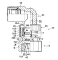
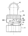
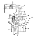
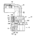
図1は、本発明の第1実施形態である継手10の分離状態を示す半裁断面図であり、図2は、この継手10の結合状態を示す半裁断面図である。   FIG. 1 is a half cut sectional view showing a separated state of the joint 10 according to the first embodiment of the present invention, and FIG. 2 is a half cut sectional view showing the coupled state of the joint 10.

これらの図に示すように、継手10は、雌型のボディー12と、雄型のノーズ40とで構成されている。この継手10は、例えばビールなどの液体を所定の圧力(例えば、約0.4MPa)で流す用途で使用されている。   As shown in these drawings, the joint 10 includes a female body 12 and a male nose 40. The joint 10 is used in an application in which a liquid such as beer is allowed to flow at a predetermined pressure (for example, about 0.4 MPa).

ボディー12は、ノーズ40が挿入される円筒状の凹状挿入部14が形成されたボディー本体16を備えている。ボディー本体16の芯部には、凹状挿入部14と連通し、液体が流れる流路部20が形成されている。ボディー本体16の後端側の内周面には、ねじ部16Aが形成されており、このねじ部16Aにボディー本体16の後端側に接続されるアダプター(図示省略)のねじ部が螺合されるようになっている。   The body 12 includes a body main body 16 in which a cylindrical concave insertion portion 14 into which a nose 40 is inserted is formed. A channel portion 20 is formed in the core portion of the body body 16 so as to communicate with the concave insertion portion 14 and through which a liquid flows. A threaded portion 16A is formed on the inner peripheral surface on the rear end side of the body main body 16, and a threaded portion of an adapter (not shown) connected to the rear end side of the body main body 16 is screwed into the threaded portion 16A. It has come to be.

ボディー本体16は、ノーズ40が挿入される凹状挿入部14の挿入口14A側の先端部16Bの内径が大きく形成されており、先端部16Bの内側には、ロック部材としての筒状のコレット22が内挿されている。コレット22とボディー本体16の先端部16Bとの間には、コレット22を凹状挿入部14内に軸方向へ移動可能に保持する筒状の保持部材24が設けられている。保持部材24の外周には凸部24Aが形成されており、保持部材24がボディー本体16の先端部16Bに圧入され、凸部24Aが先端部16Bの内側の凹部に係合されることで保持部材24が先端部16Bに固定されている。   The body main body 16 is formed with a large inner diameter of the distal end portion 16B on the insertion opening 14A side of the concave insertion portion 14 into which the nose 40 is inserted, and a cylindrical collet 22 as a lock member is provided inside the distal end portion 16B. Is interpolated. Between the collet 22 and the distal end portion 16B of the body main body 16, a cylindrical holding member 24 that holds the collet 22 in the concave insertion portion 14 so as to be movable in the axial direction is provided. A convex portion 24A is formed on the outer periphery of the holding member 24. The holding member 24 is press-fitted into the distal end portion 16B of the body main body 16, and the convex portion 24A is engaged with a concave portion inside the distal end portion 16B. The member 24 is fixed to the distal end portion 16B.

図6に示すように、コレット22は、樹脂製の筒状体からなり、筒状体の挿入口14A側の端部22Aと反対側に、軸方向に沿って形成された複数の切込み23によって略2/3の長さが切割りされている。コレット22の内周面には、複数に切割りされた端部22B側に、ノーズ40に形成された周溝44を係合する凸状部22Cが形成されている。本実施形態では、切込み23が6個形成されており、凸状部22Cが6個形成されている。コレット22は、複数の切込み23が形成されることで、複数の凸状部22Cが弾性変形により拡径が可能となっている。図2に示すように、複数の凸状部22Cは、凹状挿入部14にノーズ40が挿入されたときにノーズ40の外周面に形成された周溝44に係合されるようになっている。また、挿入口14Aと反対側に配置されるコレット22の端部22Bは、径方向外側に突出している。   As shown in FIG. 6, the collet 22 is formed of a resin-made cylindrical body, and includes a plurality of cuts 23 formed along the axial direction on the side opposite to the end portion 22A on the insertion port 14A side of the cylindrical body. A length of about 2/3 is cut. On the inner peripheral surface of the collet 22, a convex portion 22 </ b> C that engages a circumferential groove 44 formed in the nose 40 is formed on the end portion 22 </ b> B side that is cut into a plurality. In the present embodiment, six cuts 23 are formed, and six convex portions 22C are formed. The collet 22 is formed with a plurality of cuts 23 so that the plurality of convex portions 22C can be expanded in diameter by elastic deformation. As shown in FIG. 2, the plurality of convex portions 22 </ b> C are engaged with a circumferential groove 44 formed on the outer peripheral surface of the nose 40 when the nose 40 is inserted into the concave insertion portion 14. . Further, the end 22B of the collet 22 disposed on the side opposite to the insertion port 14A protrudes radially outward.

また、コレット22の外周側には、軸方向の中間部付近に径方向に突出する突起22Dが形成されている。図3に示すように、保持部材24の先端部側(挿入口14A側)には、内側に突出する突起24Bが形成されており、コレット22の突起22Dが挿入口14A側に移動したときに、保持部材24の突起24Bに突き当たることにより、コレット22の抜け出しが防止される。   Further, on the outer peripheral side of the collet 22, a protrusion 22D protruding in the radial direction is formed in the vicinity of the intermediate portion in the axial direction. As shown in FIG. 3, a protrusion 24B protruding inward is formed on the distal end side (insertion opening 14A side) of the holding member 24, and the protrusion 22D of the collet 22 moves to the insertion opening 14A side. By colliding with the protrusion 24B of the holding member 24, the collet 22 is prevented from coming off.

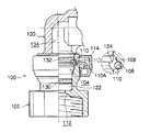
ボディー本体16の先端部16Bの外周側には、解除部材としての樹脂製のカバー26が軸方向へ移動可能に外挿されている。カバー26は、筒状の部材からなり、挿入口14A側の端部26Aが略直角方向に折り曲げられてコレット22の端部22Aと当接可能に形成されている。ボディー本体16の後方側(先端部16Bと反対側)のカバー26と隣接する位置には、ボディー本体16の外周面から突出する略円柱状の突起部30が設けられている。突起部30は、ボディー本体16の約180°の方向に2つ設けられている。カバー26の後方側の縁部には、各突起部30が移動するための2つの凹状の切り欠き部27が周方向に周長の約1/4の長さで形成されている。カバー26は、切り欠き部27の一端部27Aと他端部27Bが突起部30に当たるまでの間を周方向に回動可能となっている。このとき、切り欠き部27の一端部27Aが突起部30と当たる位置を、カバー26の軸方向の配管接続部側(ねじ部16A側)への移動をロックするロック位置A(図2参照)とし、切り欠き部27の他端部27Bが突起部30と当たる位置を、カバー26の軸方向の配管接続部側(ねじ部16A側)への移動を許容するロック解除位置B(図1参照)としている。言い換えると、カバー26は、ロック位置Aとロック解除位置Bとの間を周方向に回動可能に構成されている。   A resin cover 26 as a release member is externally attached to the outer peripheral side of the distal end portion 16B of the body main body 16 so as to be movable in the axial direction. The cover 26 is made of a cylindrical member, and is formed so that the end portion 26A on the side of the insertion port 14A is bent in a substantially right angle direction so as to be in contact with the end portion 22A of the collet 22. At a position adjacent to the cover 26 on the rear side of the body main body 16 (opposite to the front end portion 16B), a substantially cylindrical protrusion 30 protruding from the outer peripheral surface of the body main body 16 is provided. Two protrusions 30 are provided in the direction of about 180 ° of the body main body 16. At the rear edge of the cover 26, two concave cutouts 27 for moving each projection 30 are formed with a length of about ¼ of the circumferential length in the circumferential direction. The cover 26 is rotatable in the circumferential direction until the one end 27 </ b> A and the other end 27 </ b> B of the notch 27 abut against the protrusion 30. At this time, the lock position A (see FIG. 2) that locks the movement of the cover 26 in the axial direction of the pipe connection portion (screw portion 16A side) at the position where the one end portion 27A of the cutout portion 27 abuts against the projection portion 30. The unlocking position B (see FIG. 1) allows the movement of the cover 26 to the pipe connecting part side (screw part 16A side) in the axial direction at the position where the other end part 27B of the notch part 27 abuts against the protruding part 30. ). In other words, the cover 26 is configured to be rotatable between the lock position A and the lock release position B in the circumferential direction.

図1に示すように、カバー26の切り欠き部27の他端部27Bには、ボディー本体16の先端部16Bの方向に凹状に窪んだ凹部27Cが形成されており、凹部27Cがボディー本体16の突起部30と係合可能となっている。これによって、ロック解除位置Bでは、カバー26の凹部27Cをボディー本体16の突起部30と係合させることで、カバー26を軸方向の配管接続部側(ねじ部16A側)へ移動することができる。   As shown in FIG. 1, the other end 27B of the cutout 27 of the cover 26 is formed with a recess 27C that is recessed in the direction of the tip 16B of the body body 16, and the recess 27C is formed in the body body 16 as shown in FIG. The protrusion 30 can be engaged. As a result, at the lock release position B, the cover 26 can be moved to the pipe connecting portion side (the screw portion 16A side) in the axial direction by engaging the concave portion 27C of the cover 26 with the protruding portion 30 of the body main body 16. it can.

図1に示すように、カバー26の端部26Aは、挿入口14A側でコレット22の端部22Aと当接可能に形成されており、カバー26をボディー本体16の後方側(ノーズ40の挿入方向)に押し込むことで、コレット22が押されて凹状挿入部14の奥側に移動する構成となっている。その際、コレット22の奥側の端部22Bは、ボディー本体16の内周側の保持部材24の奥側に形成された溝部25に入り込むようになっている。また、カバー26の内周面には突起26Bが形成されており、ボディー本体16の先端部16Bの外周面には、カバー26の突起26Bと突き当たることでカバー26の抜け出しを防止する突起18が設けられている。   As shown in FIG. 1, the end portion 26A of the cover 26 is formed so as to be able to contact the end portion 22A of the collet 22 on the insertion port 14A side, and the cover 26 is disposed on the rear side of the body body 16 (insertion of the nose 40). The collet 22 is pushed and moved to the back side of the concave insertion portion 14 by pushing in the direction). At that time, the end 22B on the back side of the collet 22 enters the groove 25 formed on the back side of the holding member 24 on the inner peripheral side of the body main body 16. Further, a protrusion 26B is formed on the inner peripheral surface of the cover 26, and a protrusion 18 that prevents the cover 26 from coming out by abutting against the protrusion 26B of the cover 26 on the outer peripheral surface of the front end portion 16B of the body body 16. Is provided.

図7(A)には、カバー26をロック位置Aに回動した状態が示されており、図7(B)には、カバー26をロック位置Aからロック解除方向に少し回動させた状態が示されている。これらの図に示すように、カバー26の外周面には、切り欠き部27の一端部27Aと隣接する位置に径方向に突出する突起26Cが設けられている。また、カバー26の内周面と対向するボディー本体16の外周面には、突起部30に近い位置であって、突起部30に対して切り欠き部27の他端部27Bの方向に、径方向に突出する第1の凸部32が設けられている。カバー26の内周面には、切り欠き部27の一端部27Aに近い位置であって、切り欠き部27と隣接する位置に、カバー26の内側方向に突出する第2の凸部28が設けられている。ボディー本体16の第1の凸部32とカバー26の第2の凸部28は、カバー26を周方向に回動させるときに、互いに突き当たる位置に形成されている。図7(A)に示すロック位置Aでは、ボディー本体16の第1の凸部32とカバー26の第2の凸部28が近接対向するように配置されており、カバー26の第2の凸部28よりもボディー本体16の第1の凸部32が切り欠き部27の一端部27Aに近い側に位置している。そして、図7(B)に示すように、カバー26をロック解除位置Bに回動させるときに、カバー26の第2の凸部28がボディー本体16の第1の凸部32を乗り上げる必要があり、カバー26の回動が規制されるようになっている。   7A shows a state where the cover 26 is rotated to the lock position A, and FIG. 7B shows a state where the cover 26 is slightly rotated from the lock position A in the unlocking direction. It is shown. As shown in these drawings, a protrusion 26 </ b> C protruding in the radial direction is provided on the outer peripheral surface of the cover 26 at a position adjacent to the one end 27 </ b> A of the notch 27. In addition, the outer peripheral surface of the body main body 16 that faces the inner peripheral surface of the cover 26 is located near the protrusion 30 and has a diameter in the direction of the other end 27B of the notch 27 with respect to the protrusion 30. A first protrusion 32 protruding in the direction is provided. On the inner peripheral surface of the cover 26, a second convex portion 28 that protrudes inward of the cover 26 is provided at a position close to the one end portion 27 </ b> A of the notch portion 27 and adjacent to the notch portion 27. It has been. The first convex portion 32 of the body main body 16 and the second convex portion 28 of the cover 26 are formed at positions that abut each other when the cover 26 is rotated in the circumferential direction. 7A, the first convex portion 32 of the body body 16 and the second convex portion 28 of the cover 26 are disposed so as to face each other, and the second convex portion of the cover 26 is disposed. The first convex portion 32 of the body main body 16 is located closer to the one end portion 27 </ b> A of the cutout portion 27 than the portion 28. As shown in FIG. 7B, when the cover 26 is rotated to the unlock position B, the second convex portion 28 of the cover 26 needs to ride over the first convex portion 32 of the body main body 16. Yes, the rotation of the cover 26 is restricted.

第1の凸部32は、突起部30側の傾斜面32Aが緩やかな勾配に形成され、突起部30と反対側の傾斜面32Bが急勾配に形成されている。また、第2の凸部28は、凸状の湾曲面からなり、切り欠き部27の一端部27A側の傾斜面28Aが急勾配に形成され、切り欠き部27の一端部27Aと反対側の傾斜面28Aが緩やかな勾配に形成されている。これによって、カバー26をロック位置Aからロック解除位置Bに回動させるときは、第1の凸部32の急勾配の傾斜面32Bと第2の凸部28の急勾配の傾斜面28Aが当たるため、抵抗が大きくなる。また、カバー26をロック解除位置Bからロック位置Aに回動させるときは、第1の凸部32の緩やかな傾斜面32Aと第2の凸部28の緩やかな傾斜面28Bが当たるため、抵抗が小さくなる。   The first convex portion 32 has an inclined surface 32A on the protruding portion 30 side formed with a gentle gradient, and an inclined surface 32B opposite to the protruding portion 30 formed with a steep gradient. Further, the second convex portion 28 is formed of a convex curved surface, the inclined surface 28A on the one end portion 27A side of the notch portion 27 is formed with a steep slope, and the opposite side of the one end portion 27A of the notch portion 27 is formed. The inclined surface 28A is formed with a gentle gradient. Accordingly, when the cover 26 is rotated from the lock position A to the lock release position B, the steep inclined surface 32B of the first convex portion 32 and the steep inclined surface 28A of the second convex portion 28 contact each other. Therefore, the resistance increases. Further, when the cover 26 is rotated from the unlock position B to the lock position A, the gently inclined surface 32A of the first projecting portion 32 and the gently inclined surface 28B of the second projecting portion 28 come into contact with each other. Becomes smaller.

一方、図1及び図2に示すように、ノーズ40は、先端部42に行くにしたがって小径となるように形成されている。ノーズ40の周面には、前述したように、ボディー12の凹状挿入部14に挿入されたときにコレット22の凸状部22Cと係合可能な台形状の周溝44が形成されている。ノーズ40の周面には、周溝44より先端側に凹状の周溝46が形成されており、この周溝46にOリング48が嵌め込まれている。ノーズ40の芯部には、液体が流れる流路部50が形成されている。また、ノーズ40の先端部42と反対側の端部には、ホース(図示省略)が接続される接続部52が設けられている。   On the other hand, as shown in FIGS. 1 and 2, the nose 40 is formed so as to have a smaller diameter as it goes to the distal end portion 42. As described above, a trapezoidal circumferential groove 44 that can be engaged with the convex portion 22C of the collet 22 when formed in the concave insertion portion 14 of the body 12 is formed on the peripheral surface of the nose 40. A concave circumferential groove 46 is formed on the circumferential surface of the nose 40 on the tip side from the circumferential groove 44, and an O-ring 48 is fitted into the circumferential groove 46. A channel portion 50 through which a liquid flows is formed in the core portion of the nose 40. In addition, a connection portion 52 to which a hose (not shown) is connected is provided at the end portion of the nose 40 opposite to the distal end portion 42.

次に、本発明の継手10の作用について説明する。   Next, the operation of the joint 10 of the present invention will be described.

図2に示すように、ノーズ40をボディー12の凹状挿入部14に挿入した状態では、コレット22の凸状部22Cがノーズ40の周溝44に係合している。その際、カバー26をロック位置Aに回動させることで、ノーズ40が凹状挿入部14にロックされる。ロック位置Aでは、カバー26の切り欠き部27の一端部27Aがボディー本体16の突起部30に当接しており、カバー26が突起部30と干渉し、カバー26を軸方向の配管接続部側(ねじ部16A側)に移動することができない。このため、コレット22が凹状挿入部14の奥側に押し込まれることなく、ノーズ40を凹状挿入部14から引き抜くことができない。   As shown in FIG. 2, in a state where the nose 40 is inserted into the concave insertion portion 14 of the body 12, the convex portion 22 </ b> C of the collet 22 is engaged with the circumferential groove 44 of the nose 40. At that time, the nose 40 is locked to the concave insertion portion 14 by rotating the cover 26 to the lock position A. At the lock position A, one end 27A of the notch 27 of the cover 26 is in contact with the protrusion 30 of the body body 16, the cover 26 interferes with the protrusion 30, and the cover 26 is connected to the axial pipe connection portion. It cannot move to the (screw part 16A side). For this reason, the nose 40 cannot be pulled out from the concave insertion portion 14 without the collet 22 being pushed into the back side of the concave insertion portion 14.

この状態で、継手10に流体が流れると、図3に示すように、継手10に圧力が加わり(内圧が作用し)、ノーズ40が抜ける方向の力を受けて挿入口14A側に若干移動し、コレット22の突起22Dが保持部材24の突起24Bに突き当たる。これにより、コレット22の凸状部22Cとノーズ40の周溝44との係合が外れなくなり、ノーズ40の把持力が大きくなる。   In this state, when a fluid flows through the joint 10, as shown in FIG. 3, pressure is applied to the joint 10 (internal pressure is applied), and the force slightly moves toward the insertion port 14 </ b> A in response to the force in the direction in which the nose 40 comes off. The protrusion 22D of the collet 22 abuts against the protrusion 24B of the holding member 24. Thereby, the engagement between the convex portion 22C of the collet 22 and the peripheral groove 44 of the nose 40 is not released, and the gripping force of the nose 40 is increased.

図4(A)に示すように、カバー26の先端面(挿入口14A側の面)には「ロック」と「はずす」の文字が形成されており、ロック位置Aでは、カバー26の「ロック」の位置が突起部30の位置に回動している。図4及び図5に示すように、ロック位置Aでは、ボディー本体16の突起部30がカバー26の切り欠き部27の一端部27Aに当接しており、ボディー本体16の第1の凸部32が、カバー26の第2の凸部28よりも切り欠き部27の一端部27Aに近い側に位置している。この状態では、カバー26がロック解除位置Bの方向に回動しようとしても、カバー26の第2の凸部28がボディー本体16の第1の凸部32に当たり、カバー26の回動が規制される。すなわち、カバー26をロック解除位置Bに回動させるときに、カバー26の第2の凸部28がボディー本体16の第1の凸部32を乗り上げる必要があり、カバー26に第2の凸部28が第1の凸部32を乗り超える力を加えなければ、カバー26を回動させることができない。特に、図7に示すように、カバー26をロック位置Aからロック解除位置Bに回動させるときは、第1の凸部32の急勾配の傾斜面32Bと第2の凸部28の急勾配の傾斜面28Aが当たるため、抵抗が大きくカバー26が回動しにくい。このため、継手10の使用時に、不用意にカバー26がロック解除位置Bに回動することを抑制又は防止することができる。   As shown in FIG. 4A, the letters “LOCK” and “REMOVE” are formed on the front end surface of the cover 26 (the surface on the insertion port 14A side). ”Is rotated to the position of the protrusion 30. As shown in FIGS. 4 and 5, at the lock position A, the protrusion 30 of the body main body 16 is in contact with one end 27 </ b> A of the notch 27 of the cover 26, and the first protrusion 32 of the body main body 16. However, it is located on the side closer to the one end portion 27 </ b> A of the notch portion 27 than the second convex portion 28 of the cover 26. In this state, even if the cover 26 tries to rotate in the direction of the unlock position B, the second convex portion 28 of the cover 26 hits the first convex portion 32 of the body main body 16 and the rotation of the cover 26 is restricted. The That is, when the cover 26 is rotated to the unlocking position B, the second convex portion 28 of the cover 26 needs to ride on the first convex portion 32 of the body main body 16, and the second convex portion The cover 26 cannot be rotated unless the force 28 overcomes the first protrusion 32 is applied. In particular, as shown in FIG. 7, when the cover 26 is rotated from the lock position A to the lock release position B, the steep inclined surface 32 </ b> B of the first convex portion 32 and the steep slope of the second convex portion 28. Therefore, the cover 26 is difficult to rotate. For this reason, it is possible to suppress or prevent the cover 26 from being inadvertently rotated to the unlock position B when the joint 10 is used.

一方、ノーズ40をボディー12から離脱させる際には、カバー26をロック位置Aからロック解除位置Bに回動させる。図4(A)に示すように、ロック位置Aでは、カバー26の「ロック」の位置が突起部30の位置にあり、図9(A)に示すように、カバー26の「はずす」の位置が突起部30の位置にくるまでカバー26を回動させる。このとき、図7に示すように、カバー26に一定以上の力を加えて回動させることで、樹脂製のカバー26が弾性変形して第1の凸部32を乗り超える。そして、図8に示すように、カバー26を切り欠き部27の他端部27Bが突起部30と当接するロック解除位置Bへ回動させることにより、カバー26の凹部27Cと突起部30が対向する。   On the other hand, when the nose 40 is detached from the body 12, the cover 26 is rotated from the lock position A to the lock release position B. As shown in FIG. 4A, at the lock position A, the “lock” position of the cover 26 is at the position of the protrusion 30, and as shown in FIG. The cover 26 is rotated until the position of the protrusion 30 is reached. At this time, as shown in FIG. 7, the cover 26 made of resin is elastically deformed and gets over the first convex portion 32 by rotating the cover 26 with a certain force or more. Then, as shown in FIG. 8, the cover 26 is rotated to the unlocking position B where the other end 27 </ b> B of the notch 27 abuts the protrusion 30, so that the recess 27 </ b> C of the cover 26 and the protrusion 30 face each other. To do.

そして、図9〜図11に示すように、カバー26の凹部27Cと突起部30とを係合させることにより、カバー26をボディー本体16の軸方向の配管接続部側(ノーズ40の挿入方向)に押し込む。これにより、カバー26の挿入口14A側の端部26Aがコレット22の端部22Aと当接する。図12に示すように、カバー26を更にボディー本体16の軸方向の配管接続部側(ノーズ40の挿入方向)に押し込むと、コレット22の奥側の端部22Bが弾性変形して保持部材24の奥側の溝部25に入り込み、コレット22の凸状部22Cとノーズ40の周溝44との係合が外れる。この状態で、図13及び図14に示すように、ノーズ40を凹状挿入部14から引き抜くことができ、ノーズ40とボディー12とを分離することができる(図1参照)。   Then, as shown in FIGS. 9 to 11, by engaging the concave portion 27 </ b> C of the cover 26 and the protrusion 30, the cover 26 is connected to the pipe connecting portion side in the axial direction of the body body 16 (in the insertion direction of the nose 40). Push into. Thereby, the end portion 26 </ b> A on the insertion port 14 </ b> A side of the cover 26 comes into contact with the end portion 22 </ b> A of the collet 22. As shown in FIG. 12, when the cover 26 is further pushed into the axial pipe connection portion side (the insertion direction of the nose 40) of the body main body 16, the end 22 B on the back side of the collet 22 is elastically deformed to hold the holding member 24. Into the groove portion 25 on the back side, and the engagement between the convex portion 22C of the collet 22 and the peripheral groove 44 of the nose 40 is released. In this state, as shown in FIGS. 13 and 14, the nose 40 can be pulled out from the concave insertion portion 14, and the nose 40 and the body 12 can be separated (see FIG. 1).

また、ノーズ40とボディー12を結合するときは、ボディー本体16の凹状挿入部14にノーズ40を挿入する。すると、ノーズ40の周面がコレット22の凸状部22Cを押し、保持部材24の奥側の溝部25でコレット22の端部22Bが弾性変形により拡径する。そして、図11に示すように、凸状部22Cが弾性復元力によりノーズ40の周溝44に係合する。その際、カバー26をロック位置Aに回動させることで、コレット22がロックされる。カバー26をロック解除位置Bからロック位置Aに回動させるときは、第1の凸部32の緩やかな傾斜面32Aと第2の凸部28の緩やかな傾斜面28Bが当たるため、抵抗が小さくカバー26が回動しやすい。なお、継手10は、カバー26がロック位置Aにあっても、ロック解除位置Bにあっても、ボディー本体16の凹状挿入部14にノーズ40を挿入することができる。   Further, when connecting the nose 40 and the body 12, the nose 40 is inserted into the concave insertion portion 14 of the body main body 16. Then, the peripheral surface of the nose 40 pushes the convex portion 22 </ b> C of the collet 22, and the end 22 </ b> B of the collet 22 is expanded in diameter by elastic deformation in the groove portion 25 on the back side of the holding member 24. As shown in FIG. 11, the convex portion 22C engages with the circumferential groove 44 of the nose 40 by an elastic restoring force. At that time, the collet 22 is locked by rotating the cover 26 to the lock position A. When the cover 26 is rotated from the unlock position B to the lock position A, since the gentle inclined surface 32A of the first convex portion 32 and the gentle inclined surface 28B of the second convex portion 28 contact each other, the resistance is small. The cover 26 is easy to rotate. The joint 10 can insert the nose 40 into the concave insertion portion 14 of the body body 16 regardless of whether the cover 26 is in the lock position A or the lock release position B.

このような継手10では、カバー26がロック位置Aにあるときは、第1の凸部32と第2の凸部28が当たることによってカバー26の回動が規制されるため、継手10の使用時に不用意にカバー26がロック解除位置Bに回動してコレット22が軸方向奥側へ押し込まれることを防止することができる。このため、継手10にビールを流したときに、ボディー12からのノーズ40の抜けを抑制又は防止することができる。   In such a joint 10, when the cover 26 is in the lock position A, the rotation of the cover 26 is restricted by the first protrusion 32 and the second protrusion 28 coming into contact with each other. Sometimes, the cover 26 can be prevented from being inadvertently rotated to the unlock position B and the collet 22 being pushed inward in the axial direction. For this reason, when beer is poured into the joint 10, it is possible to suppress or prevent the nose 40 from coming off from the body 12.

また、筒状体からなる樹脂製のコレット22の凸状部22Cがノーズ40の周溝44と係合されるので、ノーズ40とボディー12との着脱や洗浄を繰り返しても、従来のような止め輪110(図15参照)を用いる場合に比べて、コレット22やノーズ40が磨耗、変形しにくく、ボディー12からのノーズ40の抜けを抑制することができる。また、コレット22が筒状体で形成されており、ノーズ40が斜め挿入されたときにボディー12の凹状挿入部14への引っ掛かることを抑制することができる。   Further, since the convex portion 22C of the resin collet 22 made of a cylindrical body is engaged with the circumferential groove 44 of the nose 40, even if the nose 40 and the body 12 are repeatedly attached and detached and washed, Compared to the case where the retaining ring 110 (see FIG. 15) is used, the collet 22 and the nose 40 are less likely to be worn and deformed, and the nose 40 can be prevented from coming off from the body 12. Further, the collet 22 is formed of a cylindrical body, and when the nose 40 is obliquely inserted, the collet 22 can be suppressed from being caught on the concave insertion portion 14 of the body 12.

さらに、コレット22が樹脂製であるので、コレット22を弾性変形させて凸状部22Cをノーズ40の周溝44に係合させることができ、係合部分の調整が容易である。また、カバー26及びボディー本体16が樹脂製であるので、カバー26が弾性変形しやすく、ボディー本体16の第1の凸部32とカバー26の第2の凸部28との調整が容易である。さらに、継手10の低コスト化が可能である。   Furthermore, since the collet 22 is made of resin, the collet 22 can be elastically deformed to engage the convex portion 22C with the circumferential groove 44 of the nose 40, and the engagement portion can be easily adjusted. Further, since the cover 26 and the body main body 16 are made of resin, the cover 26 is easily elastically deformed, and the first convex portion 32 of the body main body 16 and the second convex portion 28 of the cover 26 are easily adjusted. . Furthermore, the cost of the joint 10 can be reduced.

なお、上記実施形態では、カバー26のロック位置からロック解除位置への回動を規制するために、ボディー本体16の第1の凸部32とカバー26の第2の凸部28とを設けたが、これに限らず、他の形状でもよい。   In the above embodiment, the first convex portion 32 of the body body 16 and the second convex portion 28 of the cover 26 are provided in order to restrict the rotation of the cover 26 from the locked position to the unlocked position. However, the shape is not limited to this, and other shapes may be used.

なお、上記実施形態では、液体としてビールを流したが、これに限らず、炭酸飲料や、その他の流体も適用可能である。   In the above-described embodiment, beer is flowed as a liquid. However, the present invention is not limited to this, and carbonated drinks and other fluids are also applicable.

本発明の第1実施形態に係る継手のカバーをロック解除位置に回動し、ノーズとボディーを分離した状態を示す半裁断面図である。It is a half-cut sectional view which shows the state which rotated the cover of the coupling which concerns on 1st Embodiment of this invention to the lock release position, and isolate | separated the nose and the body. 本発明の第1実施形態に係る継手のノーズとボディーを結合し、カバーをロック位置に回動した状態を示す半裁断面図である。FIG. 3 is a half cut sectional view showing a state in which the nose and body of the joint according to the first embodiment of the present invention are coupled and the cover is rotated to the lock position. 図2に示す継手に圧力が作用した状態を示す半裁断面図である。FIG. 3 is a half sectional view showing a state in which pressure is applied to the joint shown in FIG. 2. (A)は図3に示す継手の平面図、(B)は継手の一部を半裁断面とした側面図、及び(C)は継手の第1の凸部と第2の凸部を示す断面図である。(A) is a plan view of the joint shown in FIG. 3, (B) is a side view with a part of the joint cut in half, and (C) is a cross section showing the first and second protrusions of the joint. FIG. 図4(B)に示す継手に対して45°の方向から見た側面図である。It is the side view seen from the direction of 45 degrees with respect to the joint shown in FIG. 4 (B). コレット単体の平面図、及び半裁断面図である。It is a top view of a single collet, and a half cut sectional view. (A)はカバーがロック位置にあるときの第1の凸部と第2の凸部付近を示す拡大断面図、(B)はカバーをロック解除位置の方向に少し回動させたときの第1の凸部と第2の凸部付近を示す拡大断面図である。(A) is an enlarged cross-sectional view showing the vicinity of the first and second protrusions when the cover is in the locked position, and (B) is the first view when the cover is slightly rotated in the direction of the unlocked position. It is an expanded sectional view showing the 1 convex part and the 2nd convex part neighborhood. 継手のカバーをロック解除位置に回動した状態を示す半裁断面図である。It is a half-cut sectional view which shows the state which rotated the cover of the coupling to the lock release position. (A)は図9に示す継手の平面図、(B)は継手の一部を半裁断面とした側面図、及び(C)は継手の第1の凸部と第2の凸部を示す断面図である。(A) is a plan view of the joint shown in FIG. 9, (B) is a side view in which a part of the joint is cut in half, and (C) is a cross section showing the first and second protrusions of the joint. FIG. 図9(B)に示す継手に対して45°の方向から見た側面図である。It is the side view seen from the direction of 45 degrees with respect to the joint shown in FIG.9 (B). ロック解除位置でカバーの凹部とボディー本体の突起部とを係合した状態を示す半裁断面図である。It is a half-cut sectional view which shows the state which engaged the recessed part of the cover, and the projection part of the body main body in the lock release position. カバーをボディー本体の軸方向の配管接続部側へ押し込み、コレットの凸状部とノーズの周溝との係合が外れた状態を示す半裁断面図である。FIG. 5 is a half cut sectional view showing a state in which the cover is pushed into the pipe connecting portion side in the axial direction of the body body and the engagement between the convex portion of the collet and the peripheral groove of the nose is released. ボディーからノーズを引き抜く過程を示す半裁断面図である。It is a half-cut sectional view showing the process of pulling out the nose from the body. ボディーからノーズを引き抜く過程を示す半裁断面図である。It is a half-cut sectional view showing the process of pulling out the nose from the body. 従来の継手のノーズとボディーを結合して圧力が作用した状態を示す半裁断面図である。It is a half-cut sectional view which shows the state which couple | bonded the nose and body of the conventional coupling, and the pressure acted. 従来の継手のノーズとボディーを分離動作における止め輪の状態を示す半裁断面図である。It is a half cut sectional view which shows the state of the retaining ring in the operation | movement which isolate | separated the nose and body of the conventional coupling.

符号の説明Explanation of symbols

10 継手
12 ボディー
14 凹状挿入部
14A 挿入口
16 ボディー本体
20 流路部
22 コレット(ロック部材)
22B 端部
22C 凸状部
24 保持部材(ボディー本体)
25 溝部(凹状挿入部の奥側)
26 カバー(解除部材)
27 切り欠き部
27C 凹部
28 第2の凸部(規制部)
28A 傾斜面
28B 傾斜面
30 突起部
32 第1の凸部(規制部)
32A 傾斜面
32B 傾斜面
40 ノーズ
44 周溝
50 流路部
A ロック位置
B ロック解除位置
DESCRIPTION OF SYMBOLS 10 Joint 12 Body 14 Recessed insertion part 14A Insertion port 16 Body main body 20 Flow path part 22 Collet (Lock member)
22B End 22C Convex 24 Holding Member (Body Body)
25 Groove (back side of concave insertion part)
26 Cover (release member)
27 Notch 27C Concave 28 Second Convex (Regulator)
28A Inclined surface 28B Inclined surface 30 Protruding portion 32 First convex portion (regulating portion)
32A Inclined surface 32B Inclined surface 40 Nose 44 Circumferential groove 50 Channel portion A Lock position B Unlock position

Claims (5)

一方の配管に接続されるノーズと、他方の配管に接続され、前記ノーズが挿入される凹状挿入部を有するボディーと、を備え、前記ノーズ及び前記ボディーに流体が流れる流路部が形成された継手であって、
前記凹状挿入部に設けられ、筒状体の軸方向に複数の切込みを備え、端部に前記ノーズの外周面に形成された周溝と係合する凸状部が形成された樹脂製のロック部材と、
ボディー本体の外周側にロック位置とロック解除位置との間を周方向に回動可能に設けられ、前記ロック解除位置で前記ボディー本体の軸方向の配管接続部側に移動し、前記ロック部材を前記凹状挿入部の奥側に押し込んで前記凸状部と前記周溝との係合を解除する解除部材と、
前記ボディー本体の外周面に形成された突起部と、
前記解除部材に設けられ、前記ロック解除位置で前記突起部と係合され、前記解除部材を軸方向の配管接続部側へ移動可能とする凹部と、
前記ボディー本体の外周面と前記解除部材の内周面との間に設けられ、前記解除部材を前記ロック位置から前記ロック解除位置に回動させるときに、前記解除部材の回動を規制する規制部と、
を有することを特徴とする継手。
A nose connected to one pipe and a body having a concave insertion part connected to the other pipe and into which the nose is inserted, and a flow path portion through which fluid flows is formed in the nose and the body. A joint,
A resin lock provided in the concave insertion portion, provided with a plurality of cuts in the axial direction of the cylindrical body, and having a convex portion that engages with a circumferential groove formed in the outer peripheral surface of the nose at the end. Members,
It is provided on the outer peripheral side of the body main body so as to be rotatable between a lock position and an unlock position in the circumferential direction, and moves to the pipe connection portion side in the axial direction of the body main body at the lock release position. A release member that pushes into the back side of the concave insertion portion to release the engagement between the convex portion and the circumferential groove;
A protrusion formed on the outer peripheral surface of the body body;
A recess provided on the release member, engaged with the protrusion at the unlock position, and capable of moving the release member toward the pipe connection portion in the axial direction;
A restriction that is provided between the outer peripheral surface of the body main body and the inner peripheral surface of the release member and restricts rotation of the release member when the release member is rotated from the lock position to the lock release position. And
A joint characterized by comprising:
前記規制部は、前記ボディー本体の外周面から径方向に突出する第1の凸部と、前記解除部材の内周面から内側に突出する第2の凸部と、を備えることを特徴とする請求項1に記載の継手。   The restricting portion includes a first convex portion protruding in a radial direction from an outer peripheral surface of the body main body, and a second convex portion protruding inward from an inner peripheral surface of the release member. The joint according to claim 1. 前記第1の凸部及び前記第2の凸部の少なくとも一方は、前記解除部材を前記ロック位置から前記ロック解除位置に回動させるときは抵抗が大きく、前記解除部材を前記ロック解除位置から前記ロック位置に回動させるときは抵抗が小さくなるように、周方向の傾斜面の角度が調整されていることを特徴とする請求項2に記載の継手。   At least one of the first protrusion and the second protrusion has a large resistance when the release member is rotated from the lock position to the lock release position, and the release member is moved from the lock release position to the lock release position. The joint according to claim 2, wherein the angle of the inclined surface in the circumferential direction is adjusted so that the resistance becomes small when rotating to the lock position. 前記ボディー本体と、前記解除部材とが樹脂で形成されていることを特徴とする請求項1から請求項3までのいずれか1項に記載の継手。   The joint according to any one of claims 1 to 3, wherein the body main body and the release member are formed of resin. 前記流体が、ビールであることを特徴とする請求項1から請求項4までのいずれか1項に記載の継手。   The joint according to any one of claims 1 to 4, wherein the fluid is beer.
JP2007179470A 2007-07-09 2007-07-09 Fitting Expired - Fee Related JP5036428B2 (en)

Priority Applications (1)

Application Number Priority Date Filing Date Title
JP2007179470A JP5036428B2 (en) 2007-07-09 2007-07-09 Fitting

Applications Claiming Priority (1)

Application Number Priority Date Filing Date Title
JP2007179470A JP5036428B2 (en) 2007-07-09 2007-07-09 Fitting

Publications (2)

Publication Number Publication Date
JP2009014165A true JP2009014165A (en) 2009-01-22
JP5036428B2 JP5036428B2 (en) 2012-09-26

Family

ID=40355294

Family Applications (1)

Application Number Title Priority Date Filing Date
JP2007179470A Expired - Fee Related JP5036428B2 (en) 2007-07-09 2007-07-09 Fitting

Country Status (1)

Country Link
JP (1) JP5036428B2 (en)

Cited By (2)

* Cited by examiner, † Cited by third party
Publication number Priority date Publication date Assignee Title
JP2010242851A (en) * 2009-04-06 2010-10-28 Bridgestone Corp Joint
JP2013228279A (en) * 2012-04-26 2013-11-07 Hioki Ee Corp Flexible sensor

Cited By (2)

* Cited by examiner, † Cited by third party
Publication number Priority date Publication date Assignee Title
JP2010242851A (en) * 2009-04-06 2010-10-28 Bridgestone Corp Joint
JP2013228279A (en) * 2012-04-26 2013-11-07 Hioki Ee Corp Flexible sensor

Also Published As

Publication number Publication date
JP5036428B2 (en) 2012-09-26

Similar Documents

Publication Publication Date Title
US8246085B2 (en) Pipe coupling and female pipe coupling member
US10663099B2 (en) Pipe coupling comprising female coupling member and male coupling member
JP5317761B2 (en) Socket for pipe joint and pipe joint
JP6240685B2 (en) Quick coupling coupling with self-reset holding mechanism
JP4914777B2 (en) Fitting
JP4701068B2 (en) Pipe fitting
JP2007127208A (en) Male/female member assembly
JP5036428B2 (en) Fitting
JP5779082B2 (en) Fitting
JP2008106920A (en) Pipe joint
JP6171508B2 (en) Pipe fitting
JP2007132473A (en) Pipe joint
JP2007292267A (en) Movement prevention means of fluid conduit
JP5436157B2 (en) Pipe fitting
JP5421606B2 (en) Pipe joint and method for disconnecting pipe joint
JP2009144755A (en) Pipe joint with anti-rotation function
JP5253024B2 (en) Connection port receiving structure and pipe fittings including the same, pipes
JP2012087837A (en) Pipe joint
JP2007292270A (en) Movement prevention means for fluid conduit
JP4845511B2 (en) Pipe fitting
JP4216672B2 (en) Stop ring and fluid equipment with stop ring
JP2010270847A (en) Movement prevention means
JP6875109B2 (en) Pipe fitting
JP2018087588A (en) Pipe joint
JP4762119B2 (en) Fitting

Legal Events

Date Code Title Description
A621 Written request for application examination

Free format text: JAPANESE INTERMEDIATE CODE: A621

Effective date: 20100607

TRDD Decision of grant or rejection written
A01 Written decision to grant a patent or to grant a registration (utility model)

Free format text: JAPANESE INTERMEDIATE CODE: A01

Effective date: 20120626

A01 Written decision to grant a patent or to grant a registration (utility model)

Free format text: JAPANESE INTERMEDIATE CODE: A01

A61 First payment of annual fees (during grant procedure)

Free format text: JAPANESE INTERMEDIATE CODE: A61

Effective date: 20120703

FPAY Renewal fee payment (event date is renewal date of database)

Free format text: PAYMENT UNTIL: 20150713

Year of fee payment: 3

R150 Certificate of patent or registration of utility model

Ref document number: 5036428

Country of ref document: JP

Free format text: JAPANESE INTERMEDIATE CODE: R150

Free format text: JAPANESE INTERMEDIATE CODE: R150

R250 Receipt of annual fees

Free format text: JAPANESE INTERMEDIATE CODE: R250

R250 Receipt of annual fees

Free format text: JAPANESE INTERMEDIATE CODE: R250

LAPS Cancellation because of no payment of annual fees