JP2009012517A - Rolling bearing unit for wheel - Google Patents
Rolling bearing unit for wheel Download PDFInfo
- Publication number
- JP2009012517A JP2009012517A JP2007173928A JP2007173928A JP2009012517A JP 2009012517 A JP2009012517 A JP 2009012517A JP 2007173928 A JP2007173928 A JP 2007173928A JP 2007173928 A JP2007173928 A JP 2007173928A JP 2009012517 A JP2009012517 A JP 2009012517A
- Authority
- JP
- Japan
- Prior art keywords
- diameter side
- side fitting
- inner ring
- wheel
- peripheral surface
- Prior art date
- Legal status (The legal status is an assumption and is not a legal conclusion. Google has not performed a legal analysis and makes no representation as to the accuracy of the status listed.)
- Pending
Links
Images


Classifications
-
- F—MECHANICAL ENGINEERING; LIGHTING; HEATING; WEAPONS; BLASTING
- F16—ENGINEERING ELEMENTS AND UNITS; GENERAL MEASURES FOR PRODUCING AND MAINTAINING EFFECTIVE FUNCTIONING OF MACHINES OR INSTALLATIONS; THERMAL INSULATION IN GENERAL
- F16C—SHAFTS; FLEXIBLE SHAFTS; ELEMENTS OR CRANKSHAFT MECHANISMS; ROTARY BODIES OTHER THAN GEARING ELEMENTS; BEARINGS
- F16C43/00—Assembling bearings
- F16C43/04—Assembling rolling-contact bearings
-
- F—MECHANICAL ENGINEERING; LIGHTING; HEATING; WEAPONS; BLASTING
- F16—ENGINEERING ELEMENTS AND UNITS; GENERAL MEASURES FOR PRODUCING AND MAINTAINING EFFECTIVE FUNCTIONING OF MACHINES OR INSTALLATIONS; THERMAL INSULATION IN GENERAL
- F16C—SHAFTS; FLEXIBLE SHAFTS; ELEMENTS OR CRANKSHAFT MECHANISMS; ROTARY BODIES OTHER THAN GEARING ELEMENTS; BEARINGS
- F16C19/00—Bearings with rolling contact, for exclusively rotary movement
- F16C19/02—Bearings with rolling contact, for exclusively rotary movement with bearing balls essentially of the same size in one or more circular rows
- F16C19/14—Bearings with rolling contact, for exclusively rotary movement with bearing balls essentially of the same size in one or more circular rows for both radial and axial load
- F16C19/18—Bearings with rolling contact, for exclusively rotary movement with bearing balls essentially of the same size in one or more circular rows for both radial and axial load with two or more rows of balls
- F16C19/181—Bearings with rolling contact, for exclusively rotary movement with bearing balls essentially of the same size in one or more circular rows for both radial and axial load with two or more rows of balls with angular contact
- F16C19/183—Bearings with rolling contact, for exclusively rotary movement with bearing balls essentially of the same size in one or more circular rows for both radial and axial load with two or more rows of balls with angular contact with two rows at opposite angles
- F16C19/184—Bearings with rolling contact, for exclusively rotary movement with bearing balls essentially of the same size in one or more circular rows for both radial and axial load with two or more rows of balls with angular contact with two rows at opposite angles in O-arrangement
- F16C19/187—Bearings with rolling contact, for exclusively rotary movement with bearing balls essentially of the same size in one or more circular rows for both radial and axial load with two or more rows of balls with angular contact with two rows at opposite angles in O-arrangement with all four raceways integrated on parts other than race rings, e.g. fourth generation hubs
-
- F—MECHANICAL ENGINEERING; LIGHTING; HEATING; WEAPONS; BLASTING
- F16—ENGINEERING ELEMENTS AND UNITS; GENERAL MEASURES FOR PRODUCING AND MAINTAINING EFFECTIVE FUNCTIONING OF MACHINES OR INSTALLATIONS; THERMAL INSULATION IN GENERAL
- F16C—SHAFTS; FLEXIBLE SHAFTS; ELEMENTS OR CRANKSHAFT MECHANISMS; ROTARY BODIES OTHER THAN GEARING ELEMENTS; BEARINGS
- F16C2326/00—Articles relating to transporting
- F16C2326/01—Parts of vehicles in general
- F16C2326/02—Wheel hubs or castors
Abstract
Description
この発明は、FR車(前置エンジン後輪駆動車)の後輪、FF車(前置エンジン前輪駆動車)の前輪、4WD車(四輪駆動車)の全輪等の駆動輪を、懸架装置に対して回転自在に支持する為に利用する車輪用転がり軸受ユニットの改良に関する。 The present invention suspends drive wheels such as rear wheels of FR vehicles (front engine rear wheel drive vehicles), front wheels of FF vehicles (front engine front wheel drive vehicles), and all wheels of 4WD vehicles (four wheel drive vehicles). The present invention relates to an improvement of a rolling bearing unit for a wheel that is used to support a device rotatably.
車輪を懸架装置に対して回転自在に支持する為に、外輪と内輪とを転動体を介して回転自在に組み合わせた車輪用転がり軸受ユニットが、各種使用されている。又、操舵輪であると同時に駆動輪でもあるFF車或は4WD車の前輪を支持する為の車輪用転がり軸受ユニットは、等速ジョイントと組み合わせて、車輪に付与された舵角に拘らず、駆動軸の回転を上記車輪に対して円滑に(等速性を確保して)伝達する必要がある。又、FR車、4WD車の後輪を支持する車輪用転がり軸受ユニットも、場合によっては等速ジョイントと組み合わせる場合がある。この様な等速ジョイントと組み合わせて、しかも比較的小型且つ軽量に構成できる車輪用転がり軸受ユニットとして従来から、特許文献1、2に記載されたものが知られている。 In order to rotatably support a wheel with respect to a suspension device, various types of wheel rolling bearing units are used in which an outer ring and an inner ring are rotatably combined via rolling elements. In addition, the wheel rolling bearing unit for supporting the front wheel of the FF vehicle or 4WD vehicle which is the steering wheel as well as the driving wheel is combined with the constant velocity joint, regardless of the steering angle given to the wheel. It is necessary to transmit the rotation of the drive shaft to the wheel smoothly (with a constant speed). Also, a rolling bearing unit for a wheel that supports the rear wheel of the FR vehicle or 4WD vehicle may be combined with a constant velocity joint in some cases. Conventionally, what was described in patent documents 1 and 2 is known as a rolling bearing unit for wheels which can be combined with such a constant velocity joint and can be configured to be relatively small and light.
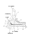
図6は、このうちの特許文献1の記載に則した構造の第1例を示している。この図6に示した車輪支持用転がり軸受ユニット1は、外輪2と、第一、第二の両内輪部材3、4を組み合わせて成るハブ5と、複数個の転動体6、6とを備える。このうちの外輪2は、車両への組み付け状態で懸架装置に支持した状態で回転しないもので、外周面にこの懸架装置に支持する為の第一の取付フランジ7を、内周面に複列の外輪軌道8、8を、それぞれ有する。上記外輪2の内径側には、上記第一、第二の内輪部材3、4を組み合わせて成る、上記ハブ5を配置している。このうちの第一の内輪部材3は、外周面の外端寄り(軸方向に関して外とは、自動車への組み付け状態で幅方向外側となる、各図の左側)部分に車輪を支持する為の第二の取付フランジ9を、同じく内端寄り(軸方向に関して内とは、自動車への組み付け状態で幅方向中央側で、各図の右側)部分に第一の内輪軌道10を、それぞれ設けている。そして、上記第一の内輪部材3の中心部に設けた円筒状部分を、内周面に雌セレーション溝11を形成した、外径側嵌合部12としている。尚、本件の明細書及び特許請求の範囲に記載した「セレーション」には、よりピッチが粗い「スプライン」も含む。
FIG. 6 shows a first example of a structure conforming to the description of Patent Document 1 among them. The wheel support rolling bearing unit 1 shown in FIG. 6 includes an outer ring 2, a
これに対して、上記第二の内輪部材4は、上記第一の内輪部材3をセレーション係合により外嵌固定する為、外周面に雄セレーション溝13を形成した内径側嵌合部14を外半部に、等速ジョイントの外輪となるハウジング部15を内端部に、第二の内輪軌道16を中間部外周面に、それぞれ設けている。そして、上記各外輪軌道8、8と上記第一、第二の内輪軌道10、16との間に、それぞれ複数個ずつの転動体6、6を設ける事により、上記外輪2の内径側に上記ハブ5を、回転自在に支持している。
On the other hand, the second
更に、上記第二の内輪部材4の外端部に位置する、上記内径側嵌合部14の先端部に形成した円筒部17を径方向外方に塑性変形させる事により造られたかしめ部18で、上記外径側嵌合部12の軸方向外端面を抑え付けている。そして、このかしめ部18と、上記ハウジング部15の外端面との間で上記外径側嵌合部12を挟持する事により、上記第一、第二の内輪部材3、4同士を結合固定して、前記ハブ5としている。尚、上記かしめ部18を形成するのに先立って、上記外径側嵌合部12の内周面に形成した雌セレーション溝11と、上記内径側嵌合部14の外周面に形成した雄セレーション溝13とを係合させる。この際、上記第一の内輪部材3の内端部内周面に設けた内周面側円筒面部19と、上記第二の内輪部材4の中間部外周面に設けた外周面側円筒面部20とを締り嵌めで嵌合させて、これら両内輪部材3、4同士の心合わせを行なう。そして、上記外径側嵌合部12の軸方向内端面を上記ハウジング部15の外端面に突き当てた状態で、上記円筒部17に揺動かしめ型25を突き当てる事により、この円筒部17を径方向外方に塑性変形させる。
Further, a
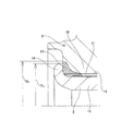
次に、図7は、前記特許文献1の記載に則した構造の第2例を示している。この図7に示した車輪支持用転がり軸受ユニット1aの場合には、上述した第1例の場合とは逆に、第一の内輪部材3aの内半部に内径側嵌合部14aを、第二の内輪部材4aの外半部に外径側嵌合部12aを、それぞれ形成している。そして、上記内径側嵌合部14aの先端部に設けた円筒部17aを径方向外方に塑性変形して成るかしめ部18aにより、上記外径側嵌合部12aの内端面を抑え付けて、上記第一、第二の内輪部材3a、4a同士を結合固定し、ハブ5aとしている。上記外径側嵌合部12aと上記内径側嵌合部14aとの設置位置を逆にし、その結果、上記両内輪部材3a、4a同士の結合部の構成各部の位置が、車両の幅方向に関して内外逆になった以外の構成及び作用は、上述した第1例の場合と同様である。
Next, FIG. 7 shows a second example of a structure conforming to the description of Patent Document 1. In the case of the wheel support rolling
上述の図6〜7に示した様な車輪支持用転がり軸受ユニット1、1aを造る場合、上記第一の内輪部材3、3aと上記第二の内輪部材4、4aとの結合強度を確保する為に、上記円筒部17、17aを上記かしめ部18、18aに塑性変形させる力を大きくする必要がある。この為、このかしめ部18、18aが、外径側嵌合部12、12aの軸方向外端面(図6に示した第1例の構造の場合)或いは内端面(図7に示した第2例の構造の場合)を強く押圧する。この様に、上記かしめ部18、18aが、外径側嵌合部12、12aの軸方向端面を押圧する力が過大になると、上記外径側嵌合部12、12aを構成する金属材料の弾性限界を超える可能性がある。そして、弾性限界を越えた場合には、上記外径側嵌合部12、12aの軸方向端面で上記かしめ部18、18aにより抑え付けられた部分が凹み(陥没し)、このかしめ部18、18aによる、上記第一の内輪部材3、3aと上記第二の内輪部材4、4aとの結合強度の確保が難しくなるだけでなく、著しい場合には、上記凹んだ部分を起点とする亀裂等の損傷を発生し易くなる。1対の内輪部材同士を、かしめ部により結合固定して成る車輪支持用転がり軸受ユニットに関して、この内輪部材の一部を焼き入れ硬化した構造を記載した刊行物として、特許文献3がある。但し、この特許文献3に記載された発明の場合、外径側嵌合部の内周面を焼き入れ硬化してはいるが、この外径側嵌合部の軸方向端面でかしめ部により抑えられる部分に関しては、特に焼き入れ硬化する事は意図していない。
When manufacturing the wheel bearing rolling
本発明は、上述の様な事情に鑑み、第一、第二の両内輪部材のうちの一方に設けられた外径側嵌合部の軸方向端面で、かしめ部により抑え付けられる部分の弾性限界を高くし、この部分を塑性変形しにくくする事により、第一、第二の両内輪部材同士の結合強度、更には耐久性を確保できる車輪用転がり軸受ユニットを実現すべく発明したものである。 In view of the circumstances as described above, the present invention provides elasticity of a portion restrained by a caulking portion at an axial end face of an outer diameter side fitting portion provided on one of the first and second inner ring members. It was invented to realize a rolling bearing unit for a wheel that can ensure the coupling strength between the first and second inner ring members and further durability by increasing the limit and making this part difficult to plastically deform. is there.
本発明の製造方法の対象となる車輪支持用転がり軸受ユニットは、前述の図6、7に示した従来構造と同様に、外輪と、第一の内輪部材と、第二の内輪部材と、複数個の転動体とを備える。
このうちの外輪は、外周面に懸架装置に支持する為の第一の取付フランジを、内周面に複列の外輪軌道を、それぞれ有する。
又、上記第一の内輪部材は、上記外輪から突出した部分の外周面に車輪を支持する為の第二の取付フランジを、上記複列の外輪軌道のうちの一端寄り部分の外輪軌道と対向する部分の外周面に第一の内輪軌道を、それぞれ設けている。
又、上記第二の内輪部材は、外周面の中間部若しくは一端寄り部分に第二の内輪軌道を有し、上記第一の内輪部材と結合固定されてハブを構成する。
又、上記各転動体は、上記各外輪軌道と上記第一、第二の内輪軌道との間に、それぞれ複数個ずつ設けている。
更に、上記第一、第二の内輪部材のうちの一方の内輪部材の少なくとも軸方向一部に外径側嵌合部を、他方の内輪部材の軸方向一部に内径側嵌合部を、それぞれ形成している。
そして、この外径側嵌合部をこの内径側嵌合部に外嵌した状態で、この内径側嵌合部の軸方向端部に設けた円筒部を径方向外方に塑性変形させる事により造られたかしめ部で、上記外径側嵌合部の軸方向端面を抑え付ける事により、上記第一、第二の内輪部材同士を結合して、上記ハブとしている。
As with the conventional structure shown in FIGS. 6 and 7, the wheel support rolling bearing unit that is the object of the manufacturing method of the present invention includes an outer ring, a first inner ring member, a second inner ring member, and a plurality of rolling bearing units. And rolling elements.
Out of these, the outer ring has a first mounting flange for supporting the suspension device on the outer peripheral surface, and a double row outer ring raceway on the inner peripheral surface.
The first inner ring member has a second mounting flange for supporting a wheel on an outer peripheral surface of a portion protruding from the outer ring, and is opposed to an outer ring raceway at a portion near one end of the double row outer ring raceway. The first inner ring raceway is provided on the outer peripheral surface of the portion to be performed.
The second inner ring member has a second inner ring raceway at an intermediate portion or one end portion of the outer peripheral surface, and is coupled and fixed to the first inner ring member to constitute a hub.
Further, a plurality of each of the rolling elements is provided between each of the outer ring raceways and the first and second inner ring raceways.
Furthermore, an outer diameter side fitting part is provided in at least a part in the axial direction of one inner ring member of the first and second inner ring members, and an inner diameter side fitting part is provided in a part in the axial direction of the other inner ring member. Each is formed.
Then, with the outer diameter side fitting portion fitted on the inner diameter side fitting portion, the cylindrical portion provided at the axial end of the inner diameter side fitting portion is plastically deformed radially outward. The first and second inner ring members are coupled to each other by pressing the axial end face of the outer diameter side fitting portion with the caulking portion thus formed, thereby forming the hub.
特に、本発明の車輪用転がり軸受ユニットに於いては、上記外径側嵌合部の軸方向端面で、上記かしめ部により抑え付けられる部分の表面部分に、熱処理硬化層を形成している。
この様な本発明を実施する場合に、好ましくは、請求項2に記載した様に、上記熱処理硬化層の外径寸法を、上記かしめ部の外径寸法よりも大きくする。
又、請求項3に記載した様に、上記熱処理硬化層を、高周波熱処理により形成する。
更に、本発明を実施する場合に、例えば請求項4に記載した様に、上記第二の内輪部材の他端部に等速ジョイントの外輪となるハウジング部を、上記外径側嵌合部の内周面に雌セレーション溝を、内径側嵌合部の外周面に雄セレーション溝を、それぞれ形成し、これら雄セレーション溝と雌セレーション溝とをセレーション係合させる。
In particular, in the wheel rolling bearing unit of the present invention, a heat-treated hardened layer is formed on the surface portion of the axially end surface of the outer diameter side fitting portion that is suppressed by the caulking portion.
When carrying out the present invention as described above, preferably, the outer diameter dimension of the heat-treated cured layer is made larger than the outer diameter dimension of the caulking portion as described in claim 2.
According to a third aspect of the present invention, the heat treatment hardened layer is formed by high frequency heat treatment.
Further, when carrying out the present invention, for example, as described in
上述の様な本発明の車輪用転がり軸受ユニットによれば、第一、第二の両内輪部材のうちの一方に設けられた外径側嵌合部の軸方向端面で、かしめ部により抑え付けられる部分の弾性限界を高くできる。この為、この部分を塑性変形しにくくする事により、第一、第二の両内輪部材同士の結合強度、更には耐久性を確保できる車輪用転がり軸受ユニットを実現できる。
特に、請求項2に記載した様に、熱処理硬化層の外径寸法を上記かしめ部の外径寸法よりも大きくすれば、このかしめ部により上記軸方向端面に加えられる力を広い範囲で支承して、上記塑性変形をより確実に防止できる。
又、請求項3に記載した様に、上記熱処理硬化層を高周波熱処理により形成すれば、所望の性状(形状、硬度)を有する熱処理硬化層を、容易に得られる。即ち、上記熱処理硬化層として、所望の性状のものを得られれば、形成の為の手段は特に問わないが、高周波熱処理によれば、高周波加熱コイルの形状、周波数、出力等を適切に調節する事で、表面積、深さ、硬度等の性状を所望通りに規制した上記熱処理硬化層を、容易に、且つ、安定して得られる。
更に、請求項4の構造により実施すれば、駆動輪用の車輪用転がり軸受ユニットの性能向上を図れる。
According to the rolling bearing unit for a wheel of the present invention as described above, it is suppressed by the caulking portion at the axial end face of the outer diameter side fitting portion provided on one of the first and second inner ring members. The elastic limit of the portion to be made can be increased. For this reason, by making this part difficult to be plastically deformed, it is possible to realize a wheel rolling bearing unit that can secure the coupling strength between the first and second inner ring members and further the durability.
In particular, as described in claim 2, if the outer diameter dimension of the heat-treated cured layer is made larger than the outer diameter dimension of the caulking portion, the force applied to the axial end face by the caulking portion is supported in a wide range. Thus, the plastic deformation can be prevented more reliably.
Further, as described in
Furthermore, if it implements by the structure of
[実施の形態の第1例]
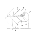
図1〜2は、全請求項に対応する、本発明の実施の形態の第1例を示している。尚、本例の特徴は、第一の内輪部材3に設けた外径側嵌合部12の軸方向外端面の一部で、かしめ部18により抑え付けられる部分に熱処理硬化層21(図1〜2に斜格子を付した部分)を形成して、この部分の硬度を高くした点にある。上記第一の内輪部材3と第二の内輪部材4とを組み合わせて成る車輪支持用転がり軸受ユニット1(図6参照)の構造及び作用に関しては、前述の特許文献1、2に記載されたものを含めて、従来構造と同様であるから、重複する図示並びに説明は、省略若しくは簡略にし、以下、本例の特徴部分を中心に説明する。
[First example of embodiment]
1 and 2 show a first example of an embodiment of the present invention corresponding to all claims. A feature of this example is a part of the outer end surface in the axial direction of the outer diameter side
本例の場合には、上記第一の内輪部材3の内径側部分に設けた外径側嵌合部12の内周面の軸方向外端寄り部分から軸方向外端面に掛けての部分に上記熱処理硬化層21を、高周波熱処理により形成している。又、上記第一の内輪部材3の外周面の軸方向中間部乃至内端部にも、別の熱処理硬化層22を形成している。この別の熱処理硬化層22は、シールリップの摺動面の摩耗防止の為、第一の内輪軌道10の転がり疲れ寿命確保の為に設けるもので、一般的な車輪用転がり軸受ユニットのものと同様で、本発明の特徴である上記熱処理硬化層21とは関係ない。但し、この熱処理硬化層21は、上記別の熱処理硬化層22と連続しない様に、独立して設けている。この理由は、硬い代わりに靱性の乏しいこれら両熱処理硬化層21、22同士が連続する事を防止して、上記第一の内輪部材3の靱性を確保する為である。
In the case of this example, on the portion of the inner peripheral surface of the outer diameter side
上記熱処理硬化層21を設けた、上記第一の内輪部材3は、第二の内輪部材4と組み合わせた状態で、かしめ部18により結合されて、ハブ5を構成している。上記熱処理硬化層21の外径D21は、このかしめ部18の外径D18よりも大きく(D21>D18)、従って、このかしめ部18は、上記熱処理硬化層21のみを抑え付けている。言い換えれば、このかしめ部18が、上記第一の内輪部材3の軸方向外端面のうちで、金属材料が生のまま(熱処理硬化せずに元の硬度のまま)の部分に突き当たる事はない。
The first
本例の車輪用転がり軸受ユニットは、上述の様に構成しているので、上記かしめ部18の加工による、上記第一、第二の両内輪部材3、4同士の結合固定に伴って、上記第一の内輪部材3に設けられた外径側嵌合部12の軸方向外端面部分を構成する金属材料の弾性限界を超える事がない。この為、上記外径側嵌合部12の軸方向外端面で上記かしめ部18により抑え付けられた部分が凹む(陥没する)事がなく、このかしめ部18による、上記第一の内輪部材3と上記第二の内輪部材4との結合強度を十分に確保できる。又、上記かしめ部18により抑え付けられた部分を起点とする亀裂等の損傷が発生する事も確実に防止できる。
Since the wheel rolling bearing unit of the present example is configured as described above, the first and second
更に、図示の例では、上記かしめ部18が直接突き当たる部分だけでなく、このかしめ部18の加工に伴って大きな応力が発生する、この部分の周囲部分、上記外径側嵌合部12の軸方向外端面と内周面とを連続させる面取り部分にも、上記熱処理硬化層21を形成している。この為、上記かしめ部18の加工に伴ってこれら各部分に、凹み、亀裂等の損傷が発生する事も、確実に防止できる。尚、上記熱処理硬化層21の深さは、一般的な乗用車用の車輪支持用転がり軸受ユニットの場合で2〜3mm程度が適切である。又、上記熱処理硬化層21の外径D21をかしめ部18の外径D18よりも大きくする程度(D21−D18)は、同様の条件で、1〜5mm程度が適切である。
Further, in the illustrated example, not only the portion where the
[実施の形態の第2例]
図3〜4も、全請求項に対応する、本発明の実施の形態の第2例を示している。本例の場合には、前述の図7に示した、従来構造の第2例に関して、本発明を適用した場合に就いて示している。この為に本例の場合には、第一の内輪部材3a側に設けた内径側嵌合部14aの先端部に設けた円筒部17aを径方向外方に塑性変形して成るかしめ部18aにより抑え付けられる、第二の内輪部材4a側に設けた外径側嵌合部12aの内端面部分に、熱処理硬化層21a(図3〜4に斜格子を付した部分)を形成している。又、本例の場合には、第二の内輪部材4aの軸方向外半部の外周面だけでなく、この第二の内輪部材4aの軸方向内半部に設けた等速ジョイントの外輪となるハウジング部15の内周面にも熱処理硬化層23を、全周に亙り形成している。その他、本発明の特徴となる部分の構成及び作用に関しては、上記実施の形態の第1例の場合と同様であるから、重複する説明は省略する。
[Second Example of Embodiment]
3 to 4 also show a second example of the embodiment of the present invention corresponding to all claims. In the case of this example, the case where the present invention is applied is shown with respect to the second example of the conventional structure shown in FIG. For this reason, in the case of this example, the
[実施の形態の第3例]
図5は、請求項1〜3に対応する、本発明の実施の形態の第3例を示している。本例の場合には、第一の内輪部材3bに設けた外径側嵌合部12の内周面の軸方向外半部に凹凸部24を、ローレット加工により形成している。そして、上記外径側嵌合部12の軸方向外端面に形成した熱処理硬化層21b(図5に斜格子を付した部分)を、上記凹凸部24部分まで延長して形成している。熱処理硬化層21bの加工を凹凸部24形成後に行なう事は勿論である。この様な本例の場合には、第二の内輪部材4bに設けた内径側嵌合部14の軸方向外端部にかしめ部18を形成するのに伴って、この内径側嵌合部14の外周面が上記凹凸24部分に食い込み、この内径側嵌合部14と上記外径側嵌合部12との相対回転を阻止して、ハブ5bを構成する。その他、本発明の特徴となる部分の構成及び作用に関しては、上記実施の形態の第1〜2例の場合と同様であるから、重複する説明は省略する。
[Third example of embodiment]
FIG. 5 shows a third example of an embodiment of the present invention corresponding to claims 1 to 3. In the case of this example, the
1、1a 車輪支持用転がり軸受ユニット
2 外輪
3、3a、3b 第一の内輪部材
4、4a、4b 第二の内輪部材
5、5a、5b ハブ
6 転動体
7 第一の取付フランジ
8 外輪軌道
9 第二の取付フランジ
10 第一の内輪軌道
11 雌セレーション溝
12、12a 外径側嵌合部
13 雄セレーション溝
14、14a 内径側嵌合部
15 ハウジング部
16 第二の内輪軌道
17、17a 円筒部
18、18a かしめ部
19 内周面側円筒面部
20 外周面側円筒面部
21、21a、21b 熱処理硬化層
22 熱処理硬化層
23 熱処理硬化層
24 凹凸部
25 揺動かしめ型
DESCRIPTION OF
Claims (4)
Priority Applications (1)
| Application Number | Priority Date | Filing Date | Title |
|---|---|---|---|
| JP2007173928A JP2009012517A (en) | 2007-07-02 | 2007-07-02 | Rolling bearing unit for wheel |
Applications Claiming Priority (1)
| Application Number | Priority Date | Filing Date | Title |
|---|---|---|---|
| JP2007173928A JP2009012517A (en) | 2007-07-02 | 2007-07-02 | Rolling bearing unit for wheel |
Publications (1)
| Publication Number | Publication Date |
|---|---|
| JP2009012517A true JP2009012517A (en) | 2009-01-22 |
Family
ID=40353957
Family Applications (1)
| Application Number | Title | Priority Date | Filing Date |
|---|---|---|---|
| JP2007173928A Pending JP2009012517A (en) | 2007-07-02 | 2007-07-02 | Rolling bearing unit for wheel |
Country Status (1)
| Country | Link |
|---|---|
| JP (1) | JP2009012517A (en) |
Cited By (2)
| Publication number | Priority date | Publication date | Assignee | Title |
|---|---|---|---|---|
| WO2015046361A1 (en) * | 2013-09-27 | 2015-04-02 | Ntn株式会社 | Production method for wheel bearing device |
| CN106763226A (en) * | 2017-02-27 | 2017-05-31 | 南京航空航天大学 | A kind of hinge set structure for being adapted to mechanical elastic vehicle wheel |
-
2007
- 2007-07-02 JP JP2007173928A patent/JP2009012517A/en active Pending
Cited By (3)
| Publication number | Priority date | Publication date | Assignee | Title |
|---|---|---|---|---|
| WO2015046361A1 (en) * | 2013-09-27 | 2015-04-02 | Ntn株式会社 | Production method for wheel bearing device |
| CN106763226A (en) * | 2017-02-27 | 2017-05-31 | 南京航空航天大学 | A kind of hinge set structure for being adapted to mechanical elastic vehicle wheel |
| CN106763226B (en) * | 2017-02-27 | 2019-05-14 | 南京航空航天大学 | A kind of hinge set structure being adapted to mechanical elastic vehicle wheel |
Similar Documents
| Publication | Publication Date | Title |
|---|---|---|
| JP3622458B2 (en) | Rolling bearing unit for wheel support | |
| JP4986116B2 (en) | Wheel bearing device | |
| JP5366665B2 (en) | Wheel bearing device | |
| JP5227158B2 (en) | Roller bearing inner ring and wheel bearing device having the same | |
| JP4604634B2 (en) | Rolling bearing device and manufacturing method thereof | |
| JP2007046703A (en) | Bearing device for driving wheel | |
| JP2002295505A (en) | Bearing device of wheel | |
| JP2010047059A (en) | Wheel bearing device and axle module | |
| WO2014069578A1 (en) | Bearing device for wheel | |
| JP2009012517A (en) | Rolling bearing unit for wheel | |
| JP2008173995A (en) | Bearing device for wheel | |
| JP2007261577A5 (en) | ||
| JP2007069704A (en) | Bearing device for driving wheel | |
| JP5193659B2 (en) | Wheel bearing device | |
| JP2010042785A (en) | Bearing device for wheel | |
| JP4894652B2 (en) | Manufacturing method of wheel bearing rolling bearing unit | |
| JP2004132552A (en) | Rolling bearing unit for supporting wheel | |
| JP2010047057A (en) | Wheel bearing device and axle module | |
| JP4904980B2 (en) | Axle bearing device | |
| EP1902861B1 (en) | Wheel rolling bearing apparatus | |
| JP2009149141A (en) | Bearing device for drive wheel | |
| JP5301175B2 (en) | Drive wheel bearing device | |
| JP2006062437A (en) | Wheel supporting device and manufacturing method thereof | |
| JP5823437B2 (en) | Manufacturing method of wheel bearing device | |
| JP2004169927A (en) | Rolling bearing unit for supporting wheel |
Legal Events
| Date | Code | Title | Description |
|---|---|---|---|
| RD04 | Notification of resignation of power of attorney |
Free format text: JAPANESE INTERMEDIATE CODE: A7424 Effective date: 20100310 |