JP2009012255A - Channel connecting device and recorder - Google Patents
Channel connecting device and recorder Download PDFInfo
- Publication number
- JP2009012255A JP2009012255A JP2007175294A JP2007175294A JP2009012255A JP 2009012255 A JP2009012255 A JP 2009012255A JP 2007175294 A JP2007175294 A JP 2007175294A JP 2007175294 A JP2007175294 A JP 2007175294A JP 2009012255 A JP2009012255 A JP 2009012255A
- Authority
- JP
- Japan
- Prior art keywords
- connector
- flow path
- valve
- ink
- negative pressure
- Prior art date
- Legal status (The legal status is an assumption and is not a legal conclusion. Google has not performed a legal analysis and makes no representation as to the accuracy of the status listed.)
- Pending
Links
Images


Classifications
-
- B—PERFORMING OPERATIONS; TRANSPORTING
- B41—PRINTING; LINING MACHINES; TYPEWRITERS; STAMPS
- B41J—TYPEWRITERS; SELECTIVE PRINTING MECHANISMS, i.e. MECHANISMS PRINTING OTHERWISE THAN FROM A FORME; CORRECTION OF TYPOGRAPHICAL ERRORS
- B41J2/00—Typewriters or selective printing mechanisms characterised by the printing or marking process for which they are designed
- B41J2/005—Typewriters or selective printing mechanisms characterised by the printing or marking process for which they are designed characterised by bringing liquid or particles selectively into contact with a printing material
- B41J2/01—Ink jet
- B41J2/17—Ink jet characterised by ink handling
- B41J2/175—Ink supply systems ; Circuit parts therefor
- B41J2/17503—Ink cartridges
- B41J2/17506—Refilling of the cartridge
- B41J2/17509—Whilst mounted in the printer
Landscapes
- Ink Jet (AREA)
Abstract
Description
本発明は液体の流路同士を自動で接続させて連通状態にしたり、離間したりする流路接続装置に関するものである。または、そのような流路接続装置によってキャリアの外部からインクを供給ようにした記録装置に関するものである。 The present invention relates to a flow path connection device that automatically connects liquid flow paths to each other and establishes communication between them. Alternatively, the present invention relates to a recording apparatus in which ink is supplied from the outside of the carrier by such a flow path connecting device.
近年のビジネス向け印刷装置は、インクの交換頻度を減らす為や、ランニングコストを押えるために印刷用インクを入れるインクタンクは大容量が要求されている。 In recent printing apparatuses for business use, an ink tank for storing printing ink is required to have a large capacity in order to reduce the frequency of ink replacement and to suppress running costs.
印刷用紙の送り方向に対して、印刷機構を搭載したキャリアを直角方向に移動しながら印刷するタイプの装置では、インクタンクは前記キャリアに搭載する方式が一般的に用いられている。 In an apparatus of a type that performs printing while moving a carrier equipped with a printing mechanism in a direction perpendicular to the feeding direction of printing paper, a system in which an ink tank is mounted on the carrier is generally used.
ただし、この方式だとキャリアの大きさや、インクタンクの重量増加によるキャリア速度の低下や、それを補う為にキャリアモータの大型化等、不利な点が発生じることがあった。そのような問題を解消するために、インクタンクをキャリアの外に置き、キャリアの印刷機構とインクタンクは、チューブで接続する方式も用いられている。 However, this method may have disadvantages such as a decrease in carrier speed due to an increase in the size of the carrier and the weight of the ink tank, and an increase in the size of the carrier motor to compensate for this. In order to solve such a problem, a system in which the ink tank is placed outside the carrier and the carrier printing mechanism and the ink tank are connected by a tube is also used.
チューブ接続方式はチューブの長さをキャリアの移動を見込んで、かなり長く設定する必要がある。また、チューブの剛性の影響を受けないキャリア移動の均一性の維持や、チューブの外部からインク内に空気が侵入したり、インクの水分がチューブ外部に蒸発したりする問題があり、チューブの材質の選定は困難な場合もあった。 In the tube connection method, it is necessary to set the length of the tube considerably long in consideration of the movement of the carrier. In addition, there are problems such as maintaining uniformity of carrier movement that is not affected by the rigidity of the tube, air entering the ink from the outside of the tube, and ink moisture evaporating to the outside of the tube. In some cases, it was difficult to select.
以上の様な問題の解決対策の一例として、特許文献1で開示されているインク供給機構が提案されている。これは、大容量インクタンクを搭載した装置本体側と印刷機構を搭載したキャリア間にインクの供給路を分割する接続機構を設たものである。本体側接続機構とキャリア側接続機構は、お互いに接続するとインク流路が出来てインクをキャリア側に供給し、離間すると各々の接続機構からインクが洩れないような機構となっている構成である。
しかし、特許文献1に記載されているような供給機構及び動作だと、接続機構を離間する時、各々の接続機構に残ったインクが飛散り、印刷用紙等を汚す可能性があった。
本発明は以上の点に鑑み、接続部からのインクの飛散りを押える機構の提案を目的とする。
However, with the supply mechanism and operation described in Patent Document 1, when the connection mechanisms are separated, there is a possibility that ink remaining in each connection mechanism will scatter and stain printing paper or the like.
The present invention has been made in view of the above points, and an object of the present invention is to propose a mechanism for suppressing the scattering of ink from a connection portion.
上記目的を達成するための本発明の構成は、
第1のコネクタを有し、流体を流す第1の流路と、
第2のコネクタを有し、流体を流す第2の流路と、
前記第1のコネクタと前記第2のコネクタの少なくとも一方を移動させて、前記第1のコネクタと前記第2のコネクタとを当接させて前記第1の流路と前記第2の流路を連通させ、前記第1のコネクタと第2のコネクタを離間させる移動手段と、
前記第1のコネクタと第2のコネクタを離間させる時に離間開始から両者間の距離が所定距離以内のときは両者間の相対速度は第1の速度以下に制御し、前記所定距離を超えたら前記第1の速度より大きい第2の速度になるように制御する制御手段と、
を有することを特徴とする流路接続装置である。
The configuration of the present invention for achieving the above object is as follows.
A first flow path having a first connector and flowing fluid;
A second flow path having a second connector and flowing fluid;
By moving at least one of the first connector and the second connector and bringing the first connector and the second connector into contact with each other, the first channel and the second channel are moved. Moving means for communicating and separating the first connector and the second connector;
When the distance between the first connector and the second connector is within a predetermined distance from the start of the separation, the relative speed between the two is controlled to be equal to or lower than the first speed, and when the distance exceeds the predetermined distance, Control means for controlling the second speed to be higher than the first speed;
It is a flow path connecting device characterized by having.
本発明によれば、第1の流路の第1のコネクタと、第2の流路の第2のコネクタを接続状態から離間させる際の流体の飛び散りを減少させることができる。 ADVANTAGE OF THE INVENTION According to this invention, the scattering of the fluid at the time of separating the 1st connector of a 1st flow path and the 2nd connector of a 2nd flow path from a connection state can be reduced.
本発明を適用した実施形態の記録装置または印刷装置1の外観図を図9、図10に示す。 9 and 10 are external views of a recording apparatus or printing apparatus 1 according to an embodiment to which the present invention is applied.
901は筐体カバー、902はメンテナンス用カバー、903は印刷用紙906を支えるガイド、904は印刷された記録媒体である印刷用紙906が排出される排紙口で矢印A方向に排出される。
907は筐体に交換可能に設置された液体を貯留するタンクとしてのインクタンク101を交換する為のカバーで、図10のように開いた状態で、インクタンク101は矢印D方向にガイドされ、筐体901側に押し込むと後述する供給口と結合する。905は電源スイッチ、である。
図2は印刷装置1の内部構成の斜視図である。
201は全体を支えるシャーシ、202は印刷用紙906を支えるプラテン、203は印刷用紙906を送るローラ、204は印刷用紙906をローラ203に押し付けるピンチローラである。図示しない駆動装置でローラ203を回転させる事により、図9矢印A方向に印刷用紙906を送る。
FIG. 2 is a perspective view of the internal configuration of the printing apparatus 1.
206はキャリアで、シャフト207とシャーシのガイド部205に沿って矢印B方向を往復移動可能に支えられる。209は、ベルト208を介してキャリア206をシャフト207とシャーシのガイド部205に沿って矢印B方向に往復移動させるモータである。
210はキャリア206に搭載される印刷機構をメンテナンスするためのメンテナンス機構である。
A
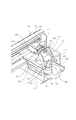
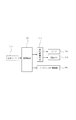
図3は印刷装置1のキャリア部分と印刷装置本体側のインク供給機構の斜視図である。図11は印刷装置1の制御ブロック図である。 FIG. 3 is a perspective view of the carrier portion of the printing apparatus 1 and the ink supply mechanism on the printing apparatus main body side. FIG. 11 is a control block diagram of the printing apparatus 1.
301はキャリア206に流体または液体としてのインクを外部から供給する機構を搭載した本体側供給機構である。本体側供給機構301はシャーシ201に支えられたシャフト302とシャーシのガイド部303によってキャリア206の移動方向Bと該直角方向の矢印C方向に往復移動可能に支えられる。
304はインクの流れを作る為の負圧を発生させる為の減圧手段としてのポンプで負圧はチューブ305、負圧接続部306を介して本体供給機構301に接続する。
307はインクタンク101と接続する供給口で、筐体カバー901の一部に結合し、インクタンク101を筐体901方向に押し込む事によってインクの洩れが無いように結合する。
A
供給口307はチューブ308、後述する弁機構としての負圧弁a309を介して本体供給機構301に接続する。
310はキャリア206側の液室としてのサブインクタンク、311は後述する弁機構としての負圧弁b、312は後述する弁機構としての負圧弁cである。
The
310 is a sub ink tank as a liquid chamber on the
313は本体側供給機構301を矢印C方向に往復移動させるためと、ポンプ304を駆動する為の回転駆動装置である。ポンプ304側は回転駆動装置313の回転方向に限らず駆動、本体側供給機構301側は図示しないワンウエイクラッチによって一方向のみの駆動を伝えるように構成される。
316は回転駆動装置313の駆動で回転する接続カムである。接続カム316のカム面は本体側供給機構301の側面301aに当接し、回転することによって本体側供給機構301をキャリア206に近づく方向に移動させる。そして、前記負圧弁a309と負圧接続部306の一部をキャリア206の背面206aに当接する位置まで移動させる。接続カム316がその小径部が側面301aに当接する初期位置まで回転すると本体側供給機構301はバネの力で移動してキャリア206から遠ざかり、負圧弁a309と負圧接続部306はキャリア206の背面206aから離間する。接続カム316と前記バネは移動手段を構成する。接続カム316と一体的に回転する円盤314には切り欠きが所定の位置に形成され、前記切り欠きを位置センサ315で検出することによって接続カム316の回転角位相を制御する。
A
回転駆動装置313及び位置センサ315は図示しない配線によって制御手段である図11の制御基板(制御回路)700につながり、制御される。
The
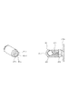
図4は本発明の実施形態の負圧接続部306及び負圧弁a309の斜視図である。
401は負圧接続部306、負圧弁a309の斜視図及び断面図である。
401は筐筒、404は弾性体で作られたシール部材、402は球状弁である。球状弁402はスプリング403によって筐筒401内部の斜面に当接していて、接触面により筐筒401に開けられた連通口401a側とシール部材404側に開けられた連通口404a側の圧力差を保持する。
FIG. 4 is a perspective view of the negative
401 is a perspective view and a cross-sectional view of the negative
401 is a casing, 404 is a sealing member made of an elastic body, and 402 is a spherical valve. The spherical valve 402 is in contact with the inclined surface inside the
ただし、負圧接続部306は上記球状弁402とスプリング403を備えておらず、筐筒401とシール部材404のみの構成である。
However, the negative
前記圧力差は、
連通口401a側圧力>シール部材404側圧力
で、スプリング403の設定によって決まり、圧力差がスプリング403の力を超えると球状弁402が筐筒401内部の斜面からはなれて、連通口401a側とシール部材404側は連通する。
The pressure difference is
シール部材404のリブ404bのシール面404c(第1の面)がキャリア背面206a(第2の面)に当接した時にリブ404bがたわみ、機密性を出す。
When the
図5はキャリア206を示し、(a)は斜視図、(b)は一部を断面にした図である。
キャリア206はシャフト207にガイドされる軸受け502及び503と、シャーシのガイド部205によって往復移動可能にガイドされる。
5A and 5B show the
The
504はインクジェット印刷機構で微細なノズルの集合体である。各ノズルに対応して吐出圧力を発生するエネルギー発生素子が設けられ、エネルギー発生素子は図示しない配線を介して本体側の制御基板700から送られてくる制御信号によって各ノズルからインクを吐出するように制御される。
505は負圧口、506は第2の開口であるインク供給口、507、508は本体側供給機構301の位置決めボス317、318との位置決めをする為の穴である。
509はサブタンク310からインクジェット印刷機構504のインク緩衝室510へのインクの流量を制御する負圧弁dで連通口511でインク緩衝室510に接続される。
前述の負圧弁a309、負圧弁b311、負圧弁c312、負圧弁d509の構成は、共に図4で説明した構成と基本的に同じになっていて、スプリングで特性を変えている。 The configurations of the negative pressure valve a309, the negative pressure valve b311, the negative pressure valve c312 and the negative pressure valve d509 are basically the same as those described with reference to FIG. 4, and the characteristics are changed by a spring.
図6(a)は印刷装置1の平面図、(b)は側面図で一部を断面で示している。 FIG. 6A is a plan view of the printing apparatus 1, and FIG. 6B is a side view showing a part thereof in cross section.
図6はキャリア206が図2の矢印B方向に往復移動し、インクジェット印刷機構504が印刷用紙903上に印刷をしている状態である。
FIG. 6 shows a state where the
インクジェット印刷機構504がインク緩衝室510内のインクを消費すると、インク緩衝室510内部は負圧になる。負圧がある一定値に達すると負圧弁d509内の球状弁509aがスプリング509bを圧縮して開き、サブタンク310内のインクがインク緩衝室510内に供給される。
When the ink
サブタンク310内のインクが減って内部が負圧になり、ある一定値に達すると、負圧弁c312内の球状弁312aが開き大気が流入する。大気がある程度流入すると負圧弁c312内のスプリング312bにより球状弁312aが閉まり、サブタンク310内の負圧は保持されインクがもれることもない。
負圧弁b311はサブタンク310側の負圧では開かず、ここからのインクの洩れは無い。
When the ink in the
The negative pressure valve b311 does not open at the negative pressure on the
図7(a)は印刷装置1の平面図、(b)は側面図で一部を断面で示している。
図7は負圧接続部306と負圧弁a309がキャリア後部206aに当接し、各々負圧口505、インク供給口506に接続した状態である。キャリア206が所定の位置に停止した状態で、本体側供給機構301を接続カム316の回転によってキャリア206側に移動させる。本体側供給機構301の位置決めボス317、318と位置決め穴507、508が係合し、本体側供給機構301とキャリア206との相互の位置決めがなされる。さらに、本体側供給機構301を移動させると負圧接続部306と負圧弁a309がそれぞれ負圧口505、インク供給口506に接続する。本実施形態では負圧弁a309が第1のコネクタ、インク供給口506を有するキャリア206の背面206aが第2のコネクタである。負圧弁a309のシール面404cが第1の面、背面206aが第2の面である。負圧弁a309のシール部材404の開口404dが第1の開口、インク供給口506が第2の開口である。
FIG. 7A is a plan view of the printing apparatus 1, and FIG. 7B is a side view showing a part in cross section.
FIG. 7 shows a state in which the negative
また、インク供給口506を移動させて負圧弁a309と接続する構成でもよい。
Further, the
この状態で負圧発生手段であるポンプ304を作動させてサブタンク310内の想定される負圧よりも高い負圧を発生させ、負圧接続部306を介して負圧弁b311に負圧をかける。負圧により負圧弁b311内のスプリング311bは負圧接続部306側の負圧に負けて球状弁311aが開き、サブタンク310内の負圧を高める。
In this state, the
サブタンク310内の負圧が高くなるとその負圧によって、第2の弁である負圧弁c312の球状弁312aがスプリング312bを圧縮して開く。すなわち、第2の流路の負圧弁c312の第2の開口側(インク供給口506側)の圧力よりもその反対側の圧力の方が所定値以上小さいので負圧弁c312は開く。さらに、開いた負圧弁c312から供給される負圧によって、第1の弁である負圧弁a309の球状弁309aがスプリング309bを圧縮して開く。すなわち、第1の流路の負圧弁a309の第1の開口側(開口404d側)の圧力よりもその反対側の圧力のほうが所定値以上大きいので負圧弁a309は開く。その結果、インクタンク101が負圧状態のサブタンク310と接続され、インクタンク101内のインクがサブタンク310に流入する。
When the negative pressure in the
この時、インクジェット印刷機構504側は負圧弁d509が逆止弁となり、インクの逆流やインクジェット印刷機構504のノズルからの空気の流入は押えられる。
At this time, the negative pressure valve d509 serves as a check valve on the
本実施形態ではインクタンク101に接続された供給口307からチューブ308、負圧弁a309までの流体の経路が第1の流路である。インク供給口506から負圧弁c312を介してサブタンク310に至る流体経路が第2の流路である。そしてサブタンク310内の負圧によって負圧弁c312および負圧弁a309が開くことによって第1の流路と第2の流路が連通する。このように第1の流路の端部の負圧弁a309と第2の流路の端部の供給口307とを接続、離間させる接続カム316や、負圧弁c312および負圧弁a309を開いて第1の流路と第2の流路を連通させるポンプ304等が流路接続装置を構成する。
In the present embodiment, the fluid path from the
所定のインク量をサブタンク310に供給すると、本体側供給機構301は接続カム316の回転によってキャリア206側から離間し、図6の位置に移動する。
When a predetermined ink amount is supplied to the
本体側供給機構301とキャリア206との離間動作の際にキャリア後部206aから負圧弁a309のシール部材404が離間する時、インクが飛散る現象が観察されている。負圧弁a309はその内部をインクが流れる為に連通口404a側周辺に残ったインクがあり、それが離間動作に連動して飛び散る。すなわち、負圧弁a309のシール部材404の開口(第一の開口)404dと、キャリア後部206aのインク供給口506との間に所定の容積を有する空間があり、その空間にインクが離間の際に飛び散るのである。
It has been observed that ink is scattered when the
インクが飛散ると、印刷用紙903を汚したり、飛散ったインクが固着すると各部の動作が不安定になる弊害がある。
If the ink is scattered, the
実験の結果、負圧弁a309とキャリア後部206aが離間する時の両者間の相対速度が所定速度以下(第1の速度以下)であればインクの飛散りは殆ど起こらない事が判明した。
As a result of the experiment, it has been found that if the relative speed between the negative pressure valve a309 and the carrier
また、当接位置から所定距離以内のときに、前記相対速度以下であればよく、それ以降は速度を上げても問題ないことも見出した。 It has also been found that when it is within a predetermined distance from the contact position, it may be equal to or less than the relative speed, and thereafter, there is no problem even if the speed is increased.
図1は負圧弁a309のシール部材404と、当接しているキャリア後部206aとの離間時のインクの挙動を示し、左側列の(a)が離間速度20mm/sec以下、右側列(b)が20mm/sec以上の場合の図である。
FIG. 1 shows the behavior of ink when the
本実施形態では接続方向が水平方向であるため、連通口404a側周辺に残ったインクは重力の影響でシール部材404の下側に集まる。
In the present embodiment, since the connection direction is the horizontal direction, the ink remaining in the vicinity of the
20mm/sec以下で離間した時、シール部材404の下側に集まったインクはシール部材404とキャリア後部206aとの間に橋601を作りながら両側に引っ張られる。橋が切れた時、インクの略全部はどちらかに吸収されてインクの飛散りは略起こらない。
When separated at 20 mm / sec or less, the ink collected on the lower side of the
ところが20mm/sec以上で離間した時、やはりシール部材404の下側に集まったインクはシール部材404とキャリア後部206aとの間に橋を作りながら両側に引っ張られる。この場合、離間速度が速いため、橋が切れる状態が不安定で、どちらにも吸収されないインク適602が残り、これが飛散るインクとなる。
However, when the ink is separated at 20 mm / sec or more, the ink collected on the lower side of the
上段より4段目でインクは離れているが、本実施形態の例ではシール部材404とキャリア後部206aとの距離(離間距離)が約4mm程度離れた時である事が確認された。
Although the ink is separated at the fourth stage from the upper stage, it was confirmed that the distance (separation distance) between the
図8は図1の実験結果に基づいて作成した、インク滴が飛び散ら無いように負圧弁a309をキャリア後部206aから離間させる速度制御の例である。図8の(a)は離間距離と速度の関係を示した的グラフである。
FIG. 8 is an example of speed control created based on the experimental results of FIG. 1 to separate the negative pressure valve a309 from the carrier
離間開始から離間距離が約4mm以下では、負圧弁a309の移動速度を第1の速度20mm/sec以下に制御する。離間距離が約4mmを超えればインクは飛び散らないので、負圧弁a309を第2の速度である20mm/sec以上で移動させることができる。本実施形態では50mm/secまで加速している。 When the separation distance is about 4 mm or less from the start of the separation, the moving speed of the negative pressure valve a309 is controlled to the first speed of 20 mm / sec or less. If the separation distance exceeds about 4 mm, the ink does not scatter, so that the negative pressure valve a309 can be moved at a second speed of 20 mm / sec or more. In this embodiment, the acceleration is up to 50 mm / sec.
図8(a)の速度1のグラフでは、4mm離間する前に20mm/secまで負圧弁a309を加速し、離間距離が4mmになるまで20mm/secの定速で移動させ、離間距離が4mmを超えたら50mm/secまで加速している。 In the graph of speed 1 in FIG. 8A, the negative pressure valve a309 is accelerated to 20 mm / sec before being separated by 4 mm, and is moved at a constant speed of 20 mm / sec until the separation distance is 4 mm. If it exceeds, it accelerates to 50mm / sec.
速度2のグラフでは離間距離が約4mmになったときに速度が20mm/secになるように、負圧弁a309を一定の加速度で加速し、離間距離が4mmを超えたらより大きな加速度で50mm/secまで加速している。
速度1の制御においても速度2の制御においてもインクの飛び散りは見られなかった。
In the graph of
No ink splattering was observed in either the speed 1 control or the
なお本実施形態で検討したインクは、常温での粘度が3.3(mPa・S)、表面張力は31(mN/m)を基準としているが、低温度環境では共に1.5倍程度になるが、離間条件の変化は無かった。従って、粘度が4mPa・sec以下の流体において同様の効果がある。また、表面張力が40mN/m以下の流体において同様の効果がある。 The inks examined in this embodiment are based on a viscosity at normal temperature of 3.3 (mPa · S) and a surface tension of 31 (mN / m), but both are about 1.5 times in a low temperature environment. However, there was no change in the separation condition. Therefore, the same effect is obtained in a fluid having a viscosity of 4 mPa · sec or less. Moreover, the same effect is obtained in a fluid having a surface tension of 40 mN / m or less.
またシール部材404の直径は5.5mmを基準としているが、部品のばらつきで6mm程度まで離間条件の変化は無かった。従ってシール部材404のシール面の直径が6mm以下であれば同様の効果がある。
The diameter of the
本実施形態では説明の簡素化のため、1色で説明したが、多色においても何ら問題なく適用できるが、その場合シール部材404の直径は6mm程度より大きくなるとキャリアの大型化となる場合もある。
In the present embodiment, the description has been made with one color for simplification of the description. However, the present invention can be applied to any color without any problem, but in that case, if the diameter of the
図8(b)は接続カム316の回転角に対する各要素の動作をまとめたチャートで、回転カム316一回転で本実施形態で説明してきた動作が完結する様になっている。
FIG. 8B is a chart summarizing the operation of each element with respect to the rotation angle of the
図8(b)において、インク供給動作が開始されると、制御回路700は回転駆動装置313によって接続カム316を回転させる。接続カム316の回転角が10度で位置センサ315の信号がLからHに切り換る。回転角20度から接続カム316は本体側供給機構301の移動を開始させる。回転角度70度において、負圧接続部306と負圧弁a309が各々負圧口505、インク供給口506に接続した図7の状態になり、本体側供給機構301は停止する。回転角90において制御回路700は回転駆動装置313によってポンプ304を駆動させ、インクタンク101内のインクをサブタンク310に供給する。回転角220度でポンプ304を停止しインク供給が終了する。回転角240度から接続カム316は本体側供給機構301をキャリア206から離間させる。接続カム316の回転角240度から300度までの間は、本体側供給機構301は20mm/secで移動する。接続カム316の回転角300度でシール部材404とキャリア後部206aとの距離(離間距離)が4mmとなる。回転角300度から340度の間においては本体側供給機構301は50mm/secで移動する。回転角360度で位置センサ315の信号がHからLに切り換る。制御回路700は位置センサ315の信号に応じて接続カム316が停止するように回転駆動機構313を制御する。
In FIG. 8B, when the ink supply operation is started, the
本実施形態ではカムの形状で本体側供給機構301の移動速度を制御しているが、たとえばモータの回転速度を制御することによって移動速度の制御を行ってもよい。
In the present embodiment, the movement speed of the main body
101 インクタンク
201 シャーシ
206 キャリア
304 ポンプ
309 負圧弁a
311 負圧弁b
312 負圧弁c
509 負圧弁d
101
311 Negative pressure valve b
312 Negative pressure valve c
509 Negative pressure valve d
Claims (20)
第2のコネクタを有し、流体を流す第2の流路と、
前記第1のコネクタと前記第2のコネクタの少なくとも一方を移動させて、前記第1のコネクタと前記第2のコネクタとを当接させて前記第1の流路と前記第2の流路を連通させ、前記第1のコネクタと第2のコネクタを離間させる移動手段と、
前記第1のコネクタと第2のコネクタを離間させる時に離間開始から両者間の距離が所定距離以内のときは両者間の相対速度は第1の速度以下に制御し、前記所定距離を超えたら前記第1の速度より大きい第2の速度になるように制御する制御手段と、
を有することを特徴とする流路接続装置。 A first flow path having a first connector and flowing fluid;
A second flow path having a second connector and flowing fluid;
By moving at least one of the first connector and the second connector and bringing the first connector and the second connector into contact with each other, the first channel and the second channel are moved. Moving means for communicating and separating the first connector and the second connector;
When the distance between the first connector and the second connector is within a predetermined distance from the start of the separation, the relative speed between the two is controlled to be equal to or lower than the first speed, and when the distance exceeds the predetermined distance, Control means for controlling the second speed to be higher than the first speed;
A flow path connecting device comprising:
前記ノズルに供給する液体を貯留する液室と、
前記液室に供給する液体を貯留するタンクと、
第1のコネクタを有し、前記タンクに接続され、液体を流す第1の流路と、
第2のコネクタを有し、前記液室に接続され、液体を流す第2の流路と、
前記第1のコネクタと前記第2のコネクタの少なくとも一方を移動させて、前記第1のコネクタと前記第2のコネクタとを当接させて前記第1の流路と前記第2の流路を連通させ、前記第1のコネクタと第2のコネクタを離間させる移動手段と、
前記第1のコネクタと第2のコネクタを離間させる時に離間開始から両者間の距離が所定距離以内のときは両者間の相対速度は第1の速度以下に制御し、前記所定距離を超えたら前記第1の速度より大きい第2の速度になるように制御する制御手段と、
を有することを特徴とする記録装置。 A nozzle for discharging liquid to perform recording on a recording medium;
A liquid chamber for storing liquid to be supplied to the nozzle;
A tank for storing liquid to be supplied to the liquid chamber;
A first flow path having a first connector, connected to the tank and flowing a liquid;
A second flow path having a second connector, connected to the liquid chamber, and for flowing a liquid;
By moving at least one of the first connector and the second connector and bringing the first connector and the second connector into contact with each other, the first channel and the second channel are moved. Moving means for communicating and separating the first connector and the second connector;
When the distance between the first connector and the second connector is within a predetermined distance from the start of the separation, the relative speed between the two is controlled to be equal to or lower than the first speed, and when the distance exceeds the predetermined distance, Control means for controlling the second speed to be higher than the first speed;
A recording apparatus comprising:
前記制御手段は、前記移動手段によって前記第1のコネクタと前記第2のコネクタを連通させ、前記減圧手段によって前記液室の圧力を下げることによって、前記第1の弁と前記第2の弁を開き、前記液室と前記タンクの圧力差によって前記タンクに貯留された液体を前記液室に供給するように前記移動手段と前記減圧手段を制御することを特徴とする請求項19に記載の記録装置。 Pressure reducing means for reducing the pressure of the liquid chamber,
The control means causes the first connector and the second connector to communicate with each other by the moving means, and reduces the pressure of the liquid chamber by the pressure reducing means, thereby causing the first valve and the second valve to move. 20. The recording according to claim 19, wherein the moving means and the pressure-reducing means are controlled to open and supply liquid stored in the tank to the liquid chamber due to a pressure difference between the liquid chamber and the tank. apparatus.
Priority Applications (4)
| Application Number | Priority Date | Filing Date | Title |
|---|---|---|---|
| JP2007175294A JP2009012255A (en) | 2007-07-03 | 2007-07-03 | Channel connecting device and recorder |
| US12/145,431 US7850292B2 (en) | 2007-07-03 | 2008-06-24 | Flow path connecting device and recording apparatus |
| EP08159207A EP2011658A1 (en) | 2007-07-03 | 2008-06-27 | Flow path connecting device and recording apparatus |
| CNA2008101359073A CN101337467A (en) | 2007-07-03 | 2008-07-03 | Flow path connecting device and recording device |
Applications Claiming Priority (1)
| Application Number | Priority Date | Filing Date | Title |
|---|---|---|---|
| JP2007175294A JP2009012255A (en) | 2007-07-03 | 2007-07-03 | Channel connecting device and recorder |
Publications (1)
| Publication Number | Publication Date |
|---|---|
| JP2009012255A true JP2009012255A (en) | 2009-01-22 |
Family
ID=39898698
Family Applications (1)
| Application Number | Title | Priority Date | Filing Date |
|---|---|---|---|
| JP2007175294A Pending JP2009012255A (en) | 2007-07-03 | 2007-07-03 | Channel connecting device and recorder |
Country Status (4)
| Country | Link |
|---|---|
| US (1) | US7850292B2 (en) |
| EP (1) | EP2011658A1 (en) |
| JP (1) | JP2009012255A (en) |
| CN (1) | CN101337467A (en) |
Families Citing this family (2)
| Publication number | Priority date | Publication date | Assignee | Title |
|---|---|---|---|---|
| JP2010228149A (en) * | 2009-03-26 | 2010-10-14 | Seiko Epson Corp | Fluid supplying apparatus, fluid ejecting apparatus, and fluid supplying method |
| US10632758B2 (en) | 2017-07-07 | 2020-04-28 | Canon Kabushiki Kaisha | Inkjet printing apparatus and control method of the same |
Family Cites Families (5)
| Publication number | Priority date | Publication date | Assignee | Title |
|---|---|---|---|---|
| US6106109A (en) * | 1997-03-03 | 2000-08-22 | Hewlett-Packard Company | Printer apparatus for periodic automated connection of ink supply valves with multiple inkjet printheads |
| US6224198B1 (en) * | 1999-04-13 | 2001-05-01 | Lexmark International, Inc. | Method and apparatus for refilling ink jet cartridges with minimum ink loss |
| JP4055346B2 (en) | 2000-10-06 | 2008-03-05 | 富士ゼロックス株式会社 | Ink supply device and inkjet recording device |
| JP2002234180A (en) * | 2001-02-09 | 2002-08-20 | Canon Inc | Ink feed unit, ink feed mechanism and ink jet recorder |
| JP2004034336A (en) * | 2002-06-28 | 2004-02-05 | Fuji Xerox Co Ltd | Ink supply unit, subink tank and inkjet recorder |
-
2007
- 2007-07-03 JP JP2007175294A patent/JP2009012255A/en active Pending
-
2008
- 2008-06-24 US US12/145,431 patent/US7850292B2/en not_active Expired - Fee Related
- 2008-06-27 EP EP08159207A patent/EP2011658A1/en not_active Withdrawn
- 2008-07-03 CN CNA2008101359073A patent/CN101337467A/en active Pending
Also Published As
| Publication number | Publication date |
|---|---|
| US7850292B2 (en) | 2010-12-14 |
| US20090009568A1 (en) | 2009-01-08 |
| EP2011658A1 (en) | 2009-01-07 |
| CN101337467A (en) | 2009-01-07 |
Similar Documents
| Publication | Publication Date | Title |
|---|---|---|
| KR100723563B1 (en) | Liquid supply system, ink tank, ink supply system, and inkjet recording apparatus | |
| JP5789999B2 (en) | Liquid ejector | |
| JP4105135B2 (en) | Ink jet head device, ink jet device, and ink supply method for ink jet head device | |
| US9358794B2 (en) | Liquid ejecting apparatus | |
| JP2008296415A (en) | Fluid feeding system and fluid jet apparatus using the system | |
| JP2019051612A (en) | Liquid discharge device and control method of liquid discharge device | |
| JP2006088493A (en) | Inkjet recording head and inkjet recorder | |
| JP2013091281A (en) | Damper and inkjet recording apparatus | |
| JP5599693B2 (en) | Inkjet printer regulator and inkjet printer | |
| JP2009126098A (en) | Liquid feeding device and its controlling method | |
| JP2009012255A (en) | Channel connecting device and recorder | |
| JP2011110850A (en) | Liquid circulating system | |
| JP2013001064A (en) | Ink supply system and recording apparatus capable of mounting the same | |
| JP2014024347A (en) | Liquid ejecting apparatus | |
| JP6311285B2 (en) | Liquid ejecting apparatus and maintenance method | |
| JP2006224565A (en) | Liquid delivering device | |
| CN114643784A (en) | Liquid ejection apparatus | |
| JP2007044929A (en) | Inkjet printer | |
| JP2006224566A (en) | Filling method | |
| JP2010120296A (en) | Liquid jet apparatus | |
| JP2010120249A (en) | Recorder | |
| JPH10202910A (en) | Method for removing bubble in ink supplying passage for ink jet recorder, and ink jet recorder suitable for the same | |
| JP2015221574A (en) | Liquid injection apparatus | |
| JP2012126011A (en) | Ink-jet recording device | |
| JP2012218358A (en) | Ink supply system and recording apparatus including the same |
Legal Events
| Date | Code | Title | Description |
|---|---|---|---|
| RD04 | Notification of resignation of power of attorney |
Free format text: JAPANESE INTERMEDIATE CODE: A7424 Effective date: 20100201 |
|
| RD01 | Notification of change of attorney |
Free format text: JAPANESE INTERMEDIATE CODE: A7421 Effective date: 20100630 |