JP2009008620A - Leakage inspection device of underground tank - Google Patents
Leakage inspection device of underground tank Download PDFInfo
- Publication number
- JP2009008620A JP2009008620A JP2007172491A JP2007172491A JP2009008620A JP 2009008620 A JP2009008620 A JP 2009008620A JP 2007172491 A JP2007172491 A JP 2007172491A JP 2007172491 A JP2007172491 A JP 2007172491A JP 2009008620 A JP2009008620 A JP 2009008620A
- Authority
- JP
- Japan
- Prior art keywords
- pressure
- inspection
- underground tank
- time
- state
- Prior art date
- Legal status (The legal status is an assumption and is not a legal conclusion. Google has not performed a legal analysis and makes no representation as to the accuracy of the status listed.)
- Granted
Links
- 238000007689 inspection Methods 0.000 title claims abstract description 208
- 238000012790 confirmation Methods 0.000 claims abstract description 55
- 238000000034 method Methods 0.000 claims description 60
- 230000008569 process Effects 0.000 claims description 58
- 230000008859 change Effects 0.000 claims description 27
- 238000001514 detection method Methods 0.000 claims description 22
- 238000005259 measurement Methods 0.000 claims description 21
- 238000009530 blood pressure measurement Methods 0.000 claims description 4
- 238000012544 monitoring process Methods 0.000 claims description 4
- 230000000903 blocking effect Effects 0.000 claims description 2
- 230000007704 transition Effects 0.000 abstract description 15
- 238000012545 processing Methods 0.000 abstract description 11
- 239000007792 gaseous phase Substances 0.000 abstract description 6
- 230000000977 initiatory effect Effects 0.000 abstract 2
- 230000002401 inhibitory effect Effects 0.000 abstract 1
- 239000007789 gas Substances 0.000 description 78
- 239000012071 phase Substances 0.000 description 68
- 238000012360 testing method Methods 0.000 description 28
- 230000006837 decompression Effects 0.000 description 16
- IJGRMHOSHXDMSA-UHFFFAOYSA-N Atomic nitrogen Chemical compound N#N IJGRMHOSHXDMSA-UHFFFAOYSA-N 0.000 description 12
- 229910001873 dinitrogen Inorganic materials 0.000 description 12
- 239000000446 fuel Substances 0.000 description 7
- 238000010586 diagram Methods 0.000 description 5
- 239000007788 liquid Substances 0.000 description 5
- 238000012546 transfer Methods 0.000 description 5
- 230000004397 blinking Effects 0.000 description 4
- 239000000295 fuel oil Substances 0.000 description 4
- 239000003921 oil Substances 0.000 description 4
- 238000002347 injection Methods 0.000 description 3
- 239000007924 injection Substances 0.000 description 3
- 239000007791 liquid phase Substances 0.000 description 3
- 230000009467 reduction Effects 0.000 description 3
- 230000009471 action Effects 0.000 description 2
- 238000013459 approach Methods 0.000 description 2
- 238000004891 communication Methods 0.000 description 2
- 230000007812 deficiency Effects 0.000 description 2
- 239000000463 material Substances 0.000 description 2
- 238000011946 reduction process Methods 0.000 description 2
- 238000009423 ventilation Methods 0.000 description 2
- 206010000369 Accident Diseases 0.000 description 1
- 238000011109 contamination Methods 0.000 description 1
- 238000005538 encapsulation Methods 0.000 description 1
- 239000000945 filler Substances 0.000 description 1
- 230000006870 function Effects 0.000 description 1
- 238000003780 insertion Methods 0.000 description 1
- 230000037431 insertion Effects 0.000 description 1
- 230000002035 prolonged effect Effects 0.000 description 1
- 238000007789 sealing Methods 0.000 description 1
- 239000002689 soil Substances 0.000 description 1
- 230000002123 temporal effect Effects 0.000 description 1
- 230000036962 time dependent Effects 0.000 description 1
- 230000001052 transient effect Effects 0.000 description 1
- 239000012808 vapor phase Substances 0.000 description 1
- 238000005303 weighing Methods 0.000 description 1
Images


Abstract
Description
本発明は、地下タンクに貯蔵された液体の洩れの有無を検査する地下タンクの漏洩検査装置に係り、特に地下タンク内の気相部からの洩れを検知するのに好適な地下タンクの漏洩検査装置に関する。 The present invention relates to an underground tank leakage inspection apparatus for inspecting whether or not a liquid stored in an underground tank leaks, and more particularly to an underground tank leakage inspection suitable for detecting leakage from a gas phase portion in the underground tank. Relates to the device.
従来、ガソリンをはじめとする燃料油等の危険物を地下タンクに貯蔵する貯蔵所等においては、地下タンクからの燃料油等の漏洩による土壌汚染,火災事故等の予防のために、地下タンクの気密漏洩検査を定期的に行うことが、法令により義務付けられている。 Conventionally, in reservoirs where dangerous materials such as gasoline and other fuel oil are stored in underground tanks, in order to prevent soil contamination and fire accidents due to leakage of fuel oil etc. from underground tanks, It is mandatory by law to conduct airtight leak inspections regularly.
地下に埋設され、内部に燃料油等の危険物を貯蔵する地下タンクの気密漏洩検査に関しては、液を貯蔵したままで気密漏洩検査を行う場合、地下タンク内の空間部分である気相部と、燃料油等の液が貯蔵された部分である液相部との双方について、それぞれ漏洩検査を行うことが義務付けられている。 Regarding the airtight leak inspection of underground tanks buried underground and storing dangerous materials such as fuel oil, when performing airtight leak inspection with liquid stored, the gas phase part which is the space part in the underground tank In addition, it is obliged to conduct a leakage inspection on both the liquid phase part, which is a part where the liquid such as fuel oil is stored.
地下タンク内の気相部の気密漏洩検査は、例えば、大気圧に対し、気相部の圧力状態を所定の微加圧状態P0(2kPa)にして地下タンクを密閉保持し、その後の気相部の圧力変化から漏洩の有・無を判定する微加圧検査の場合、次に述べるような手順で行われる。 For example, an airtight leak inspection of the gas phase portion in the underground tank is performed by holding the underground tank hermetically with the pressure state of the gas phase portion set to a predetermined slightly pressurized state P 0 (2 kPa) with respect to the atmospheric pressure. In the case of a slight pressurization test for determining the presence or absence of leakage from the pressure change of the phase part, the following procedure is performed.
図10は、微加圧検査についての説明図である。
まず、漏洩検査装置に含まれる圧力計測機器や加圧装置等の機器調整等を行う。そして、圧力計測機器を地下タンク内の気相部に接続するとともに、微加圧装置を地下タンク内の気相部に接続する。そして、地下タンクと連通しているその他の接続部、例えば、液面計や検知口等の開口部分を閉塞して、地下タンクを外部に対して密閉状態にする。
FIG. 10 is an explanatory diagram of the fine pressure test.
First, adjustment of equipment such as a pressure measuring device and a pressurizing device included in the leakage inspection apparatus is performed. And while connecting a pressure measuring device to the gaseous-phase part in an underground tank, a slight pressurization apparatus is connected to the gaseous-phase part in an underground tank. Then, other connecting portions communicating with the underground tank, for example, opening portions such as a liquid level gauge and a detection port are closed, and the underground tank is sealed from the outside.
それから、この密閉状態にした地下タンク内の気相部の圧力状態を、所定時間(5分間以上)監視し、地下タンク内,地下タンクに連通する配管内の雰囲気が安定状態(平衡状態)になっていることを確認する。 Then, the pressure state of the gas phase in the sealed underground tank is monitored for a predetermined time (more than 5 minutes), and the atmosphere in the underground tank and the piping connected to the underground tank is stable (equilibrium). Make sure that
この確認後、高圧の封入ガス(窒素ガス)を供給するための加圧装置の供給操作、及びこの加圧装置に接続されている開閉弁の開弁操作を行い、地下タンク内の気相部へ封入ガスの封入を開始し、地下タンク内の気相部の加圧を開始する(図10、T0)。 After this confirmation, the operation of supplying the pressurizing device for supplying high-pressure sealed gas (nitrogen gas) and the opening / closing operation of the on-off valve connected to the pressurizing device are performed, and the gas phase section in the underground tank Sealing of the gas is started, and pressurization of the gas phase in the underground tank is started (FIG. 10, T 0 ).
地下タンク内の気相部に対しての封入ガスによる加圧開始後は、地下タンク内の気相部の圧力状態を圧力計測機器の測定出力によって監視する。必要に応じて、開閉弁の開弁量を調整しながら、概ね気相部(空間容積)1m3当たり1分間以上の時間をかけるようにして、地下タンク内の気相部へ封入ガスを徐々に封入していく。これにより、地下タンク内の気相部の圧力は、所定の検査圧力値P0になるように加圧されていく(図10、T1)。 After the start of pressurization with the sealed gas to the gas phase part in the underground tank, the pressure state of the gas phase part in the underground tank is monitored by the measurement output of the pressure measuring device. Adjust the valve opening amount of the on-off valve as necessary, and gradually fill the gas phase in the underground tank to the gas phase in the underground tank by taking about 1 minute or more per 1 m 3 of the gas phase (space volume). Enclose in. As a result, the pressure in the gas phase section in the underground tank is pressurized to a predetermined inspection pressure value P 0 (FIG. 10, T 1 ).
地下タンク内の気相部の圧力が検査圧力値P0近くでは、この気相部の圧力が検査圧力値P0に対して過加圧にならないように、開閉弁の開弁量を調整操作して、さらに徐々に加圧していく(図10、T2)。 At a pressure in the vapor phase inspection pressure value P 0 near the underground tank, so that the pressure of the gas phase portion does not become over-pressurized relative to the examination pressure value P 0, the adjustment operation of the valve opening amount of the opening and closing valve Then, the pressure is further gradually increased (FIG. 10, T 2 ).
その後、圧力計測機器の測定出力が検査圧力値P0に達したならば、開閉弁を閉弁操作して封入ガスの封入を停止し、地下タンク内の気相部の気密を保って、加圧装置を地下タンクから切り離す(図10、T3)。 Thereafter, if the measured output of the pressure measuring unit has reached the test pressure value P 0, the on-off valve and closing operation stops encapsulation of filler gas, while maintaining the airtightness of the gas phase portion in the underground tanks, pressurized The pressure device is disconnected from the underground tank (FIG. 10, T 3 ).
その後、検査対象の地下タンクの容量等に基づき予め定められている検査測定時間(例えば、30分)の間、圧力計測機器の測定出力に基づいて、検査圧力値P0に加圧され密閉された地下タンク内の気相部の圧力の経時圧力変化を監視し、その経時圧力変化(この場合は、圧力減少変化)の状態に基づいて地下タンク内の気相部の漏洩判定を行う(図10、T4)。 Thereafter, during a predetermined inspection measurement time (for example, 30 minutes) based on the capacity of the underground tank to be inspected, the inspection pressure value P 0 is pressurized and sealed based on the measurement output of the pressure measuring device. The change in pressure of the gas phase in the underground tank over time is monitored, and leakage of the gas phase in the underground tank is determined based on the state of the change in pressure over time (in this case, the pressure decrease change) (Fig. 10, T 4).
例えば、検査対象の地下タンクの容量が10kL以下である場合は、この経時圧力変化の状態に基づく地下タンク内の気相部の漏洩判定処理は、式(1),式(2)に示すようにして行われ、式(2)を満たす場合は、「地下タンクは異常なし(地下タンク内の気相部の漏洩はなし)」と判定するようになっている。
・ ΔP=P15−P30 式(1)
P15:検査圧力値P0に加圧されてから、15分経過後の地下タンク内の気相 部の圧力
P30:検査圧力値P0に加圧されてから、30分経過後の地下タンク内の気相 部の圧力
・ (ΔP/P0)×100≦2〔%〕 式(2)
For example, when the capacity of the underground tank to be inspected is 10 kL or less, the leakage judgment processing of the gas phase portion in the underground tank based on the state of the pressure change with time is as shown in Expression (1) and Expression (2). When the equation (2) is satisfied, it is determined that “the underground tank is normal (the gas phase portion in the underground tank is not leaked)”.
ΔP = P 15 −P 30 formula (1)
P 15: the pressurized to test
なお、ここでは説明省略したが、地下タンク内の気相部の圧力状態を大気圧に対して所定の減圧状態(2kPaの負圧状態)にして地下タンクを密閉保持し、その後の地下タンク内の気相部の経時圧力変化から漏洩の有・無を判定する微減圧検査の場合は、微加圧装置に代えて微減圧装置を用い、地下タンクの気相部を所定の検査圧力値P0’(ただし、この場合、検査圧力値P0’は負圧値である)にする。その際も、減圧装置及び開閉弁を操作作業する点では、微加圧検査の場合と変わりない。 Although not described here, the pressure state of the gas phase in the underground tank is set to a predetermined reduced pressure state (a negative pressure state of 2 kPa) with respect to the atmospheric pressure, and the underground tank is hermetically held, and then the inside of the underground tank In the case of the micro decompression inspection for determining the presence / absence of leakage from the change in the pressure of the gas phase portion over time, a micro decompression device is used instead of the micro pressurization device, and the gas phase portion of the underground tank is set to a predetermined inspection pressure value P 0 ′ (however, in this case, the inspection pressure value P 0 ′ is a negative pressure value). Even in this case, the operation of the pressure reducing device and the on-off valve is the same as in the case of the slightly pressurized test.
ところで、上述した如くの従来の漏洩検査では、微加圧検査における地下タンクの検査圧力値P0までの微加圧工程にしろ、微減圧検査における検査圧力値P0’までの微減圧工程にしろ、その圧力調整作業が面倒であった。 By the way, in the conventional leakage inspection as described above, in the fine pressure reduction process up to the inspection pressure value P 0 ′ in the fine pressure reduction inspection, the fine pressure reduction process up to the inspection pressure value P 0 of the underground tank in the fine pressure inspection is performed. However, the pressure adjustment work was troublesome.
作業者は、圧力計測機器を監視しながら、給気路(排気路)途中に設けられた開閉弁を操作して、地下タンク内の気相部の圧力が検査圧力値P0(P0’)に保持されるように、加圧調整(減圧調整)する。 The operator while monitoring the pressure measuring unit, supply passageway by operating the (exhaust path) off valve which is halfway provided, pressure test pressure value of the gas phase portion in the underground tanks P 0 (P 0 ' ) Is adjusted so that the pressure is maintained.
しかしながら、地下タンク形状,タンクに連通した配管配置,圧力計測機器の配置等は、検査対象の地下タンク毎に異なり、さらに、気相部の容量等は、検査の都度、異なっている。そのため、地下タンク内の気相部の圧力を検査圧力値P0(P0’)に設定保持する作業は、このような検査環境に対する考慮も必要になり、熟練を要する面倒な作業であった。 However, the shape of the underground tank, the arrangement of pipes connected to the tank, the arrangement of pressure measuring devices, and the like differ for each underground tank to be inspected, and the capacity of the gas phase portion differs for each inspection. Therefore, the work of setting and maintaining the pressure in the gas phase portion in the underground tank at the inspection pressure value P 0 (P 0 ′) requires consideration to such an inspection environment, and is a troublesome work requiring skill. .
その一方で、漏洩検査装置は、微加圧検査にしろ、微減圧検査にしろ、地下タンク内の気相部の圧力が所定の検査圧力値P0(P0’)、又はその近傍の所定値になったならば、その経時圧力変化を測定し始め、その測定結果に基づいて、地下タンク内の気相部についての漏洩判定処理を行う制御構成になっていた。 On the other hand, the leak inspection apparatus, whether it is a micro-pressure test or a micro-decompression test, the pressure in the gas phase in the underground tank is a predetermined test pressure value P 0 (P 0 ′) or a predetermined value in the vicinity thereof. When the value is reached, the control configuration starts to measure the change in pressure over time, and performs a leakage determination process for the gas phase portion in the underground tank based on the measurement result.
この結果、地下タンク内の気相部の上述した微加圧調整作業又は微減圧調整作業の仕方によって、例えば、開閉弁を検査圧力値P0(P0’)になっていないにもかかわらず早めに閉弁してしまったような場合や、また圧力計測機器による測定値が検査圧力値になったとき開閉弁を閉弁操作してもその操作遅れが生じたような場合には、地下タンク内の気相部の圧力状態に、検査圧力値P0(P0’)に対する過不足が生じてしまう。 As a result, for example, the on-off valve is not at the inspection pressure value P 0 (P 0 ′) depending on the above-described fine pressure adjustment operation or fine pressure adjustment operation of the gas phase portion in the underground tank. If the valve closes early, or if the measured value measured by the pressure measuring device reaches the inspection pressure value, and the operation delay occurs even if the on / off valve is closed, the underground An excess or deficiency with respect to the inspection pressure value P 0 (P 0 ′) occurs in the pressure state of the gas phase portion in the tank.
このような場合、漏洩検査装置は、地下タンク内の気相部の圧力に検査圧力値P0,P0’に過不足が生じているため正確な漏洩判定が行えない、と判断し、既に開始した漏洩判定処理を途中で強制終了してしまう等のケースがあった。 In such a case, the leakage inspection apparatus determines that an accurate leakage determination cannot be made because the inspection pressure values P 0 and P 0 ′ are excessive or insufficient in the pressure of the gas phase in the underground tank. There was a case where the leak determination process that was started was forcibly terminated in the middle.
そして、漏洩検査装置の漏洩判定処理の強制終了が生じた場合は、作業者は、地下タンク内の気相部の上述した微加圧調整作業又は微減圧調整作業を、最初からやり直してから、漏洩検査装置の漏洩判定処理を実行させなければならないため、検査作業時間が長時間化し、検査作業のスループットの向上がはかれなかった。 And when the forced termination of the leakage judgment process of the leakage inspection apparatus has occurred, the worker must perform the above-described fine pressure adjustment work or fine pressure adjustment work of the gas phase part in the underground tank again from the beginning, Since the leakage determination processing of the leakage inspection apparatus has to be executed, the inspection work time is prolonged and the inspection work throughput is not improved.
本発明は、上述した問題点を鑑みなされたものであって、地下タンク内の気相部の検査圧力値に対する微加圧調整作業又は微減圧調整作業を、作業者が容易かつ確実に行えるようにするとともに、検査作業時間の長時間化を抑制して、検査作業のスループットの向上がはかれるようにした漏洩検査装置を提供することを目的とする。 The present invention has been made in view of the above-described problems, and allows a worker to easily and reliably perform a fine pressure adjustment operation or a fine pressure reduction adjustment operation for an inspection pressure value of a gas phase portion in an underground tank. In addition, an object of the present invention is to provide a leakage inspection apparatus that suppresses an increase in inspection work time and improves the inspection work throughput.
上述した課題を解決するために、本発明の地下タンクの漏洩検査装置は、圧力計測機器による地下タンク内の気相部の圧力の測定値が、検査圧力値に対応した所定圧力にいたった時点で、漏洩判定処理を開始する前に、漏洩判定処理に移行できるか否かの判定を行えるようにしたことを、第1の特徴とする。 In order to solve the above-described problem, the underground tank leakage inspection apparatus according to the present invention is configured such that when the pressure measurement value of the gas phase portion in the underground tank reaches a predetermined pressure corresponding to the inspection pressure value. Thus, the first feature is that it is possible to determine whether or not it is possible to shift to the leakage determination process before starting the leakage determination process.
また、本発明の地下タンクの漏洩検査装置は、検査対象の地下タンク毎、又は検査の都度毎に異なる加圧又は減圧調整作業状況を考慮して、開閉手段の最適開・閉作動量を案内できるようしたことを、第2の特徴とする。 In addition, the underground tank leakage inspection apparatus of the present invention guides the optimum opening / closing operation amount of the opening / closing means in consideration of different pressurization or decompression adjustment work situations for each underground tank to be inspected or for each inspection. What has been made possible is the second feature.
そのために、本発明の地下タンクの漏洩検査装置は、地下タンクに接続され、地下タンク内の圧力状態を加圧状態又は減圧状態にする加圧/減圧手段と;地下タンクと該加圧/減圧手段との間の連通路に設けられ、当該連通路を連通・遮断する開閉手段と; 地下タンク内の圧力を計測する圧力計測手段と;前記加圧/減圧手段の作動及び前記開閉手段の開作動によって加圧又は減圧され、その後の前記開閉手段の閉作動によって所定の検査圧力に密閉保持された地下タンク内の当該密閉保持後の経時圧力変化を前記圧力計測手段の計測出力に基づき監視し、当該経時圧力変化の状態に基づいて地下タンクの漏洩判定を行う漏洩検査手段と;を備えた地下タンクの漏洩検査装置であって、前記所定の検査圧力値を範囲内に含む、下限圧力値及び上限圧力値によって規定される確認圧力範囲を記憶する記憶手段と;前記加圧/減圧手段の作動及び前記開閉手段の開・閉作動による、前記所定の検査圧力に対する地下タンク内の圧力調整過程で、地下タンク内の圧力が確認圧力範囲の上限値よりも小さい当該範囲内の第1の閾値を超えたことを検出する圧力確認検出手段と;該圧力確認検出手段の検出時からの経過時刻を計時する計時手段と;該計時手段の計時に基づいて、前記圧力確認検出手段の検出時からの経過時刻が予め定められた予備判定時間になったことを検出する予備判定時間検出手段と;該予備判定時間検出手段による予備判定時間の検出時に、地下タンク内の圧力が確認圧力範囲内にあるか否かを判定する検査開始予備判定手段と;前記計時手段の計時に基づいて、該検査開始予備判定手段による確認圧力範囲内の判定時からの経過時刻が予め定められた検査開始判定時間になったことを検出する検査開始判定手段と;該検査開始判定手段による検査開始判定時間の検出時に、地下タンク内の圧力が確認圧力範囲内で、当該範囲内の第2の閾値以上になっているか否かに基づいて、検査開始可・否を判定する検査開始判定手段と;を備え、前記検査手段は、前記検査開始判定手段からの検査開始可の判定出力によって、漏洩判定のための地下タンク内の経時圧力変化の監視を開始することを特徴とする。 For this purpose, the underground tank leakage inspection apparatus of the present invention is connected to the underground tank, and pressurizing / depressurizing means for making the pressure state in the underground tank a pressurized state or a depressurized state; An opening / closing means provided in a communication path with the means for communicating / blocking the communication path; a pressure measuring means for measuring a pressure in the underground tank; an operation of the pressurizing / depressurizing means and an opening / closing of the opening / closing means. Based on the measurement output of the pressure measuring means, the pressure change over time in the underground tank that has been pressurized or depressurized by the operation and then closed and held at a predetermined inspection pressure by the closing operation of the opening / closing means is monitored. Leakage inspection means for determining leakage of an underground tank based on the state of the pressure change over time, and a leakage inspection device for an underground tank, the lower limit pressure value including the predetermined inspection pressure value within the range And Storage means for storing a confirmation pressure range defined by an upper limit pressure value; in the pressure adjustment process in the underground tank with respect to the predetermined inspection pressure by the operation of the pressurizing / depressurizing means and the opening / closing operation of the opening / closing means A pressure confirmation detection means for detecting that the pressure in the underground tank has exceeded a first threshold value in the range smaller than the upper limit value of the confirmation pressure range; and an elapsed time from the detection time of the pressure confirmation detection means; Time measuring means for timing; preliminary determination time detecting means for detecting, based on the time measured by the time measuring means, that the elapsed time from the detection by the pressure confirmation detecting means has reached a predetermined preliminary determination time; An inspection start preliminary determination unit that determines whether or not the pressure in the underground tank is within the confirmation pressure range when the preliminary determination time is detected by the preliminary determination time detection unit; Inspection start determination means for detecting that the elapsed time from the determination within the confirmation pressure range by the inspection start preliminary determination means has reached a predetermined inspection start determination time; and the inspection start determination time of the inspection start determination means Inspection start determination means for determining whether or not the inspection can be started based on whether or not the pressure in the underground tank is equal to or higher than a second threshold value within the confirmation pressure range at the time of detection. The inspection means starts monitoring the change in pressure over time in the underground tank for leakage determination by a determination output indicating that inspection can be started from the inspection start determination means.
また、本発明の地下タンクの漏洩検査装置は、さらに、作業進行状態を画面表示する状態表示手段と;前記圧力計測手段に計測される地下タンク内の圧力に基づいて、現在の地下タンク内の圧力状態に対応した前記開閉手段の最適開・閉作動量を演算する最適開・閉作動量演算手段と;を備え、前記状態表示手段には、圧力調整過程状態の画面表示として、前記圧力計測手段に計測される地下タンク内の圧力に基づいた圧力調整過程における圧力変化状態と;前記最適開・閉作動量演算手段によって演算される前記開閉手段の最適開・閉作動量と;が、グラフ表示されることを特徴とする。 The underground tank leakage inspection apparatus according to the present invention further includes a status display means for displaying the progress of work on the screen; and based on the pressure in the underground tank measured by the pressure measuring means, And an optimum opening / closing operation amount calculating means for calculating an optimum opening / closing operation amount of the opening / closing means corresponding to the pressure state, wherein the state display means displays the pressure measurement as a screen display of a pressure adjustment process state. The pressure change state in the pressure adjustment process based on the pressure in the underground tank measured by the means; and the optimum opening / closing action amount of the opening / closing means calculated by the optimum opening / closing action amount computing means; It is displayed.
本発明によれば、地下タンク内の液相部の圧力上昇又は圧力下降状況と、第1,第2の閾値との比較において、漏洩検査装置は、漏洩判定処理を開始する前に、事前に漏洩判定処理を開始してよいか否かを判定することができ、漏洩判定処理を開始できないと判定した場合には、漏洩判定処理は開始されないので、地下タンク内の気相部の微加圧調整作業又は微減圧調整作業を速やかに続けてやり直すことができ、また、地下タンクの密閉部分の密閉状態の確認処理や他の詳細検査処理への移行も可能になるので、検査作業時間の長時間化を抑制し、検査作業のスループットの向上がはかれる。 According to the present invention, in the comparison between the pressure increase or decrease state of the liquid phase in the underground tank and the first and second threshold values, the leak inspection apparatus can It is possible to determine whether or not the leakage determination process can be started, and when it is determined that the leakage determination process cannot be started, the leakage determination process is not started, so that the gas phase portion in the underground tank is slightly pressurized. The adjustment work or fine decompression adjustment work can be carried out quickly and again, and it is possible to check the sealed state of the sealed part of the underground tank and shift to another detailed inspection process. Time is suppressed and the throughput of inspection work can be improved.
また、本発明によれば、さらに、作業進行状態を画面表示する状態表示手段に、地下タンク内の気相部の微加圧調整作業又は微減圧調整作業の実行中に、現在の地下タンク内の圧力状態に対応した開閉手段の最適開・閉作動量を案内表示することができるので、作業者は、この案内表示された最適開・閉作動量に習って開閉手段を作動操作することにより、検査環境状態についての細かい配慮なしに、微加圧調整作業又は微減圧調整作業をやり直すことなく、地下タンクの気相部の圧力を正確に検査圧力値に設定保持することができる確率が高まり、微加圧調整作業又は微減圧調整作業が容易になる。 Further, according to the present invention, the state display means for displaying the work progress state on the screen further displays the current underground tank while the fine pressure adjustment work or the fine pressure adjustment work of the gas phase portion in the underground tank is being performed. The optimum opening / closing operation amount of the opening / closing means corresponding to the pressure state can be guided and displayed, so that the operator operates the opening / closing means according to the optimum opening / closing operation amount displayed by the guidance. The probability that the pressure in the gas phase part of the underground tank can be accurately set and maintained at the inspection pressure value without reconsidering the fine pressurization adjustment work or the fine decompression adjustment work without detailed consideration of the inspection environment state is increased. The fine pressure adjustment work or the fine pressure reduction work becomes easy.
以下、本発明の地下タンクの漏洩検査装置に係り、その実施の形態について、図面に基づき説明する。 DESCRIPTION OF EMBODIMENTS Hereinafter, an embodiment of an underground tank leakage inspection apparatus according to the present invention will be described with reference to the drawings.
図1は、本発明の一実施の形態に係る地下タンクの漏洩検査装置を用いた漏洩検査システムの構成図である。 FIG. 1 is a configuration diagram of a leakage inspection system using an underground tank leakage inspection apparatus according to an embodiment of the present invention.
この漏洩検査システムは、本発明の一実施の形態に係る漏洩検査装置1を、車両等に燃料を供給するための給油所の地下タンク10の漏洩検査装置に適用した例を示す。
This leakage inspection system shows an example in which the
図1において、地下タンク10は地中に埋設されており、地下タンク10には、吸引管11、注油管13、通気管15、及び計量管17が接続されている。
In FIG. 1, the
吸引管11は、地下タンク10内に貯留されている燃料を計量機60に供給するためのものであって、地下タンク10内の液相部Lに連通し、その途中には逆止弁12が設けられている。
The
注入管13は、タンクローリ車のタンク等から地下タンク10内へ燃料を供給するためのものであって、タンクローリ車からの燃料注入を受けない通常時は、その注油口14が密封されている。
The
通気管15は、計量機60内部のポンプ(図示せず)による地下タンク10からの燃料吸引時やタンクローリ車から地下タンク10への燃料注入時のような、地下タンク10内で圧力変化が起きるような場合でも、地下タンク10内の圧力を大気圧に保つようにするものであって、その途中には開閉バルブ16が設けられている。この開閉バルブ16は漏洩検査を行う時に閉弁操作される。
The
計量管17は、日常点検時に地下タンク10内の残存燃料量を計測するための検尺棒が挿入されるもので、通常その挿入口は蓋封されている。この計量管17は後述する検出継手40を地下タンク10に接続するために利用される。
The measuring tube 17 is inserted with a measuring rod for measuring the amount of remaining fuel in the
次に、検査部20の構成について説明する。
本例の場合、検査部20には、検査方法に応じて、微減圧検査手段21、微加圧検査手段22、加圧検査手段23が備えられており、これらの中のいずれかの検査手段が、開閉弁30,検出継手40を介して、計量管17に接続されるようになっている。なお、これら微減圧検査手段21,微加圧検査手段22,加圧検査手段23と、計量管17との間の連通接続は、通常はなされておらず、地下タンク10の漏洩検査時に作業者が手作業で行うようになっている。
Next, the configuration of the
In the case of this example, the
微減圧検査手段21は、微減圧手段24,開閉弁30,検出継手40,圧力伝送器50を構成要素としているものであって、地下タンク10内を微減圧(2kPa)にした状態で一定時間の経時圧力変化(圧力上昇変化)を計測することにより、漏洩の有無を確認するものである。
The micro decompression inspection means 21 is composed of the micro decompression means 24, the on-off
微減圧手段24,開閉弁30,検出継手40,計量管17の間は接続ホース25・26によって互いに接続されており、微減圧手段24内の排気ポンプが駆動されることにより、これら接続ホース25・26を通じて地下タンク10内の気体が吸入されて地下タンク10内が減圧されるようになっている。
The fine
また、圧力伝送器50は、接続ホース27を介して検出継手40に接続されており、これにより地下タンク10内の圧力を検出できるとともに、検出した圧力データを、ケーブル51及びインターフェイス52を介して制御部2に伝送するようになっている。
The
また、検出継手40には温度計41が設けられており、この温度計41によって地下タンク10内の気相部の温度が検出されるようになっている。
The detection joint 40 is provided with a
微加圧検査手段22は、地下タンク10内に窒素ガスを封入して微加圧(2kPa)し、一定時間の経時圧力変動(圧力下降変化)を計測することにより、地下タンク10内の気相部の漏洩の有無を確認するものである。具体的には、微減圧検査手段21の微減圧手段24に代えて、微加圧手段28が設けられている点に特徴を有する。
The fine pressurization inspection means 22 encloses nitrogen gas in the
この微加圧手段28は、窒素ガス容器から接続ホース、減圧弁を介して供給される窒素ガスを、接続ホース25,開閉弁30,検出継手40,接続ホース26を介して、地下タンク10内に供給して、地下タンク10を加圧するものである。
The fine pressurizing means 28 supplies the nitrogen gas supplied from the nitrogen gas container via the connection hose and the pressure reducing valve to the inside of the
そして、微加圧手段28によって微加圧された地下タンク10内の圧力は、圧力伝送器50にて検出され、さらに該圧力伝送器50にて検出された圧力は圧力データとして制御部2に伝送されるようになっている。
Then, the pressure in the
加圧検査手段23は、地下タンク10内の油液を全て抜き取った後、地下タンク10内に例えば窒素ガス封入することにより加圧し、所定の試験圧力又は最大常用圧力で加圧状態を維持し、一定時間の経時圧力変動(圧力下降変化)を計測することにより漏洩の有無を確認するものである。具体的には、微減圧検査手段21の微減圧手段24、微加圧検査手段22の微加圧手段28に代えて、加圧手段29が設けられていることを特徴とする。
The
この加圧手段29は、例えば、窒素ガスが高圧状態で貯留される窒素ガス容器であって、窒素ガス容器内の高圧窒素ガスが、接続ホース25,開閉弁30,検出継手40,接続ホース26を介して、地下タンク10内に供給されることによって、地下タンク10内が加圧されるようになっている。
The pressurizing means 29 is, for example, a nitrogen gas container in which nitrogen gas is stored in a high pressure state. The high pressure nitrogen gas in the nitrogen gas container is connected to the
そして、窒素ガス容器から窒素ガスが供給された場合には、このときの地下タンク10内の圧力が圧力伝送器50にて検出され、さらに圧力伝送器50にて検出された圧力は、圧力データとして制御部2に伝送されるようになっている。
When nitrogen gas is supplied from the nitrogen gas container, the pressure in the
本例では、微減圧検査手段21,微加圧検査手段22、及び加圧検査手段23では、地下タンク10に対しての減圧又は加圧の供給及び停止を、接続ホース25に介在している開閉弁30を作業者が開閉操作して行っているが、これに代えて、微減圧手段24,微加圧手段28,加圧手段29の駆動・停止操作を作業者が行うようにしてもよい。
制御部2は、例えば、上述した微減圧検査,微加圧検査,加圧検査いずれかの指定を含む操作部3からの各種操作入力や、インターフェイス52を介して供給される圧力伝送器50の測定出力(圧力データ)に基づいて、記憶手段4に記憶されている対応する検査処理プログラムや検査データを基に、地下タンク10内の気相部Gの現在圧力や経時圧力変化の演算算出処理、図10で説明した漏洩判定処理を含む一連の漏洩検査処理、後述する地下タンク10内の気相部Gの検査圧力値P0に対しての圧力調整作業中における開閉弁30の最適開・閉作動量の算出処理、ユーザに対するこれら処理結果や作業案内に関してのディスプレイ装置5を用いた表示処理、等の各種処理を実行する。この制御部2は、例えば、操作部3,記憶手段4,ディスプレイ装置5とともに、パーソナルコンピュータによって構成されている。
In this example, in the fine decompression inspection means 21, the fine pressurization inspection means 22, and the pressurization inspection means 23, supply or stop of decompression or pressurization to the
For example, the
次に、本実施の形態の漏洩検査装置1を、地下タンク10内の気相部Gの微加圧検査による漏洩検査に用いる場合を例に、漏洩検査処理において、漏洩判定処理を行うに当たって実行する、地下タンク10内の気相部Gの圧力を検査圧力値P0にする微加圧調整作業について、図2に基づいて説明する。
Next, the
図2は、微加圧検査の際の、検査圧力値に対する微加圧調整作業中における地下タンク内の気相部の圧力状態の説明図である。 FIG. 2 is an explanatory diagram of the pressure state of the gas phase portion in the underground tank during the fine pressurization adjustment operation with respect to the inspection pressure value at the time of the fine pressurization inspection.
図2は、圧力伝送器50の測定出力に基づいて制御部2によって演算・算出された、図10中に示された「加圧時間(微加圧調整作業中)」区間部分の、地下タンク10内の気相部Gの実際の圧力状態の経時変化を示したものである。
FIG. 2 shows an underground tank in the “pressurization time (during slight pressurization adjustment work)” section shown in FIG. 10 calculated and calculated by the
図中、P0Sは、地下タンク10内の気相部Gの漏洩判定処理を行うための予め設定された検査圧力値P0(2kPa)を示し、圧力値‘0’は大気圧を示す。
In the figure, P 0S indicates a preset inspection pressure value P 0 (2 kPa) for performing the leakage determination process of the gas phase portion G in the
また、時刻‘t0’は、図10で示した「加圧時間」区間部分先頭、すなわち加圧開始に当たって、地下タンク10内,地下タンク10に連通する配管11,13,15,17内の雰囲気が安定状態(平衡状態)になっていることが確認されている状態時を示している。そのため、地下タンク10内は、既に、地下タンク10外の雰囲気に対して切り離され、密閉状態になっている。
Further, the time “t0” is the head of the “pressurization time” section shown in FIG. 10, that is, the atmosphere in the
ユーザは、この密閉状態において、微加圧手段28による封入ガス(窒素ガス)の供給開始操作,開閉弁30の開弁操作といった、地下タンク10内の気相部Gへの封入ガスの供給操作を行って、地下タンク10内の気相部Gの加圧を開始する。そして、地下タンク内の気相部の圧力が所定の検査圧力値P0Sになるように、ディスプレイ装置5に表示される圧力伝送器50からの圧力データに基づく地下タンク10内の気相部Gの圧力状態の測定出力を確認しながら、加圧していく。
In this sealed state, the user performs the operation of supplying the sealed gas to the gas phase portion G in the
そして、地下タンク10内の気相部Gの圧力PGが検査圧力値P0S近くでは、地下タンク10内の気相部Gの圧力が検査圧力値P0Sに対して過加圧にならないように、開閉弁30の開弁量を調整しながら、さらに徐々に加圧していく。
Then, a pressure P G inspection pressure value P 0S nearby gas phase G of the
その後、作業者は、圧力伝送器50の測定出力が検査圧力値P0Sに達したならば、開閉弁30を閉弁操作して封入ガスの封入を停止し、地下タンク10内の気相部Gの気密を保って、微加圧手段28を地下タンク10から切り離す。
Thereafter, when the measurement output of the
しかしながら、例えば、開閉弁30を圧力伝送器50による一時的な検査圧力値P0Sの測定に基づき閉弁してしまったような場合や、また圧力伝送器50による測定値が検査圧力値P0Sになったときの開閉弁30の閉弁操作遅れが生じたような場合や、地下タンク10内の気相部Gの圧力PGが検査圧力値P0S近くになったときの、開閉弁30の開弁量の調整が少なかったような場合等は、地下タンク10内の気相部Gの圧力PGが、図2中の線ABC’又は線ABC”に示すようになってしまい、検査圧力値P0Sに対する過不足が、予め誤差として生じてしまう。
However, for example, when the opening and closing
そこで、本実施の形態の漏洩検査装置1は、その記憶手段4に、検査圧力値P0Sを範囲内に含む、下限圧力値P0L及び上限圧力値P0Hによって規定される確認圧力範囲Wを記憶しており、予備判定時間tB(=t2〜t3)と、検査開始判定時間tS(=t3〜t4)とを記憶している構成になっている。さらに、本実施の形態の漏洩検査装置1は、その記憶手段4に、確認圧力範囲の上限値P0Hよりも小さい当該範囲内の第1の閾値PS1、及び同じく確認圧力範囲内の第2の閾値PS2として、図2に示した例では、P0S(=PS1)と、P0S(=PS2)とを記憶している構成になっている。
Therefore,
その上で、制御部2は、漏洩検査処理において、漏洩判定処理を行うに当たって、これら予め設定された確認圧力範囲W(P0L,P0H),予備判定時間tB,検査開始判定時間tS,第1の閾値PS1,第2の閾値PS2に基づいて、図3に示すような検査開始移行確認処理を行うようになっている。
In addition, when performing the leakage determination process in the leakage inspection process, the
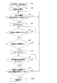
図3は、検査開始移行確認処理のフローチャートである。
図3に示すように、制御部2は、圧力伝送器50の測定出力に基づいて、随時又は常時、地下タンク10内の気相部Gの圧力状態PGを測定している(ステップS10,S20)。
FIG. 3 is a flowchart of the inspection start transition confirmation process.
3, the
その上で、制御部2は、圧力伝送器50の測定出力に基づく地下タンク10内の気相部Gの圧力状態PGが、第1の閾値PS1、すなわちこの場合は検査圧力値P0Sを超えたか否かを確認している(ステップS30)。制御部2は、地下タンク10内の圧力状態PGが検査圧力値P0Sを超えたならば、タイマをリセット・スタートし(ステップS40)、予備判定時間tB(=t2〜t3)の計時を開始する(ステップS50)。これに対し、制御部2は、地下タンク10内の圧力状態PGが第1の閾値PS1(検査圧力値P0S)を超えていないならば、ステップS30の処理を繰り返し行い、作業者が再び地下タンク10内の気相部Gの圧力状態PGを調整するのを待つ等し、現状のままでは検査処理に移行しない。
Then, the
一方、制御部2は、予備判定時間tB(=t2〜t3)の計時を行ったならば(ステップS50)、タイマによる予備判定時間tBの計時を終了し、地下タンク10内の圧力状態PGが、確認圧力範囲W(P0L,P0H)内にあるか否かを確認する(ステップS60)。
On the other hand, if the
そして、制御部2は、地下タンク10内の圧力状態PGが確認圧力範囲W(P0L,P0H)内にある場合は、タイマをリセット・スタートし、今度は検査開始判定時間tS(=t3〜t4)の計時を開始する(ステップS70)。これに対し、制御部2は、制御部2は、地下タンク10内の圧力状態PGが確認圧力範囲Wを逸脱してしまっている場合は、ステップS30の処理を繰り返し行い、作業者が再び地下タンク10内の気相部Gの圧力状態PGを調整するのを待つ等し、現状のままでは検査処理に移行しない。
Then, the
一方、制御部2は、検査開始判定時間tS(=t3〜t4)の計時を行ったならば(ステップS80)、タイマによる検査開始判定時間tSの計時を終了し、地下タンク10内の圧力状態PGが、第2の閾値PS2、すなわちこの場合は検査圧力値P0Sを超えているか否かを確認する(ステップS90)。制御部2は、地下タンク10内の圧力状態PGが検査圧力値P0Sを超えているならば、タイマによる検査開始判定時間tSを終了し、検査処理に移行する(ステップS100)。これに対し、制御部2は、地下タンク10内の圧力状態PGが第2の閾値PS2(検査圧力値P0S)を超えていないならば、ステップS30の処理を繰り返し行い、作業者が再び地下タンク10内の気相部Gの圧力状態PGを調整するのを待つ等し、現状のままでは検査処理に移行しない。
On the other hand, if the
このように、制御部2は、検査処理に移行する前に、検査開始移行確認処理を行うことができるので、検査作業時間の長時間化を抑制し、検査作業のスループットの向上がはかれることができる。
As described above, the
なお、図3に示した検査開始移行確認処理では、第1の閾値PS1,第2の閾値PS2として同じ検査圧力値P0Sを適用した。この場合、確認圧力範囲Wの下限圧力値P0L自体を検査圧力値P0Sにして、確認圧力範囲W自体を狭めることも可能である。また、第1の閾値PS1として確認圧力範囲Wの下限圧力値P0L自体を適用することも可能である。 In the inspection start transition confirmation process shown in FIG. 3, the same inspection pressure value P 0S is applied as the first threshold value P S1 and the second threshold value P S2 . In this case, it is also possible to narrow the confirmation pressure range W itself by setting the lower limit pressure value P 0L itself of the confirmation pressure range W to the inspection pressure value P 0S . Moreover, it is also possible to apply the lower limit pressure value P 0L itself of the confirmation pressure range W as the first threshold value P S1 .
いずれにしても、このような予備判定時間tB及び検査開始判定時間tSといった複数の計時要素を含めて検査処理への移行を確認するようにしたので、例えば、開閉弁30を圧力伝送器50の一時的な検査圧力値P0Sの測定に基づき閉弁操作してしまったような場合や、また圧力伝送器50による測定値PGが検査圧力値P0Sになったときの開閉弁30の閉弁操作遅れが生じたような場合であっても、現状のままでは漏洩判定処理には移行せず、漏洩判定処理への移行が制限されるので、漏洩判定結果も各検査間で統一性の取れた、確度の高いものになる。
In any case, since the transition to the inspection process is confirmed including a plurality of timing elements such as the preliminary determination time t B and the inspection start determination time t S , for example, the on-off
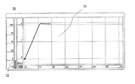
図4〜図6は、上述した検査開始移行確認処理中に、ディスプレイ装置の表示画面上に表示される検査開始移行確認処理の状態確認ウィンドウの説明図である。 4 to 6 are explanatory diagrams of a state confirmation window of the inspection start transition confirmation process displayed on the display screen of the display device during the above-described inspection start transition confirmation process.
さらに、本実施の形態の漏洩検査装置1では、上述した検査開始移行確認処理が実行されている間、制御部2によってディスプレイ装置5の表示画面上に、状態確認ウィンドウ70が表示される。
Furthermore, in the
状態確認ウィンドウ70は、圧力状態経過案内部71と、封入ガスの封入操作量案内部72を備えている。
The
圧力状態経過案内部71は、地下タンク10内の気相部Gへの封入ガスの供給操作開始後(図2における、t0以降)の、圧力伝送器50から供給される気相部Gの圧力状態(圧力値)PGの経時的変化がわかるように、その時間経過毎に対応した気相部Gの圧力値PGが、制御部2によってグラフ表示されるようになっている。この気相部Gの圧力値PGは、圧力伝送器50から制御部2に随時供給されている測定値PGに基づくものである。
The pressure state progress guide 71 is a pressure of the gas phase portion G supplied from the
封入操作量案内部72は、図示の例では、微加圧手段28の単位時間当たりの封入ガスの供給量を、微加圧手段28の最大封入能力100%として、現在の封入進行状態すなわち微加圧進行状態では、その何%程度の能力での封入ガスの封入が適切であるかを、バーグラフ表示する構成になっている。すなわち、上述した漏洩検査装置1における開閉弁30の最適開・閉作動量が案内される構成になっている。
In the illustrated example, the filling operation
この最適開・閉作動量を得るために、制御部2は、現在の地下タンク10内の圧力状態に対応した開閉弁30の最適開・閉作動量を演算する最適開・閉作動量演算手段としての機能を含んでいる。
In order to obtain the optimum opening / closing operation amount, the
この場合、制御手段2は、最適開・閉作動量演算手段として、例えば、次のようにして、最適開・閉作動量を演算する。 In this case, the control means 2 calculates the optimum opening / closing operation amount as the optimum opening / closing operation amount calculating means, for example, as follows.
すなわち、制御部2では、圧力伝送器50から制御部2に随時供給されている測定値PGに基づいて、現在の地下タンク10内の圧力状態PGと、現在の地下タンク10内の圧力状態PGの圧力状態の変化速度が逐次得られる。本実施の形態では、現在の地下タンク10内の圧力状態PGの検査圧力値P0Sに対する到達度と、現在の地下タンク10内の圧力状態PGの変化速度と、及び現在に地下タンク10内の圧力状態PGに至るまでの地下タンク10内の圧力状態PGの変化速度の変化率との3者関係から、開閉弁30の最適開・閉作動量を、全開状態を100%として演算算出する構成になっている。
That is, the
図4〜図6は、検査圧力値P0Sに対する現在の地下タンク10内の圧力状態PGの違いに応じて算出された開閉弁30の最適開・閉作動量の違いを表したものである。
4-6 is a representation of the difference between the optimum opening and closing operation of the opening and closing
例えば、図4に示すように、地下タンク10内の気相部Gへの封入ガスの供給開始当初から、地下タンク10内の気相部Gの圧力状態PGが検査圧力値P0Sに近づくまでは、概ね気相部1m3当たり1分間以上の時間をかけるようにした上での最大の開・閉作動量(例えば、100%)が、最適開・閉作動量として案内表示されている。
そして、図5に示すように、確認圧力範囲W(P0L,P0H)の下限値P0Hに地下タンク10内の圧力状態PGが近づくにつれて、最適開・閉作動量としての開閉弁30の開・閉作動量は減少し始める。
For example, as shown in FIG. 4, from the supply beginning of fill gas into the gas phase G of the
Then, as shown in FIG. 5, check the pressure range W (P 0L, P 0H) approaches the pressure state P G
図6に示すように、確認圧力範囲Wの下限値P0Hに地下タンク10内の圧力状態PGになると、本例の場合は、最適開・閉作動量としての開閉弁30の開・閉作動量は閉弁状態に対応した作動量(例えば、0%)になり、最終的に開閉弁30の閉弁が案内される。
As shown in FIG. 6, when a pressure state P G
図7は、検査開始移行確認処理における検査開始判定処理中の状態(図3のステップS90の状態)を示している。 FIG. 7 shows a state during the inspection start determination process in the inspection start shift confirmation process (the state in step S90 in FIG. 3).
このように、封入操作量案内部72には、検査環境状態についての細かい配慮なしに、加圧又は減圧調整作業をやり直すことなく、地下タンク10の気相部Gの圧力を正確に検査圧力値に設定保持することができる確率が高まる。
As described above, the sealed operation
また、検査開始移行確認処理における検査開始判定処理が終了し、検査に移行すると(図3のステップS100の状態)、制御部2によって、図7に示した状態確認ウィンドウ70の表示から、図8に示した検査状態ウィンドウ70に、自動的に表示切り替えされ、検査開始移行確認処理から検査開始判定処理に移行したことを作業者は理解できるようになっている。
When the inspection start determination process in the inspection start transition confirmation process is completed and the process proceeds to the inspection (the state in step S100 in FIG. 3), the
本実施の形態による漏洩検査装置は以上説明したとおりであるが、本発明は上述した実施形態に限られるものではない。 The leak inspection apparatus according to the present embodiment is as described above, but the present invention is not limited to the above-described embodiment.
上述の実施例では、図4から図8には検査開始移行確認処理の状態確認ウィンドウ70のみしか示していないが、ディスプレイ装置の表示画面上にこの状態確認ウィンドウ70を含んで表示される計測モニター画面上で表示するようにしてもよい。
In the above-described embodiment, only the
図9は、計測モニター画面の一実施例を示したものである。
計測モニター画面90の中の状態確認ウィンドウ70の上側に、入力諸条件項目92と実際の入力値93とが併設された対応表91において、入力諸条件項目の中に計測圧力値に該当する表示部位94を、実際の計測値が上限値を越えた際に、点滅表示等させるようにしてもよい。点滅の形態としては、(1)数値自体を点滅させる、(2)数値入力部位の背景を点滅させる(3)表全体を点滅させる等がある。また、併せて、警報音を発生させるようにしてもよい。さらに、図示はしていないが、検出継手40と計測管17との間に電磁弁を設け、実際の計測値が上限値を越えた際に、この電磁弁に信号を送り、自動的に圧力上昇を停止させるようにしても良い。
FIG. 9 shows an embodiment of the measurement monitor screen.
In the correspondence table 91 in which the input
上述した実施の形態の漏洩検査装置1は、検査部20は、微減圧検査手段21、微加圧検査手段22、加圧検査手段23全てを備えている構成としたが、検査部20は、これらの検査手段のうちのいずれかを備えておればよい。
In the
また、上述した実施の形態の漏洩検査装置1では、検査開始移行確認処理について、微加圧検査処理の場合を例に説明したが、微減圧検査処理や、加圧検査処理の場合も、上述した確認圧力範囲Wをはじめとする各種設定値や、移行判定の大小判別を適宜変更すれば、容易に適用できることは説明するまでもない。
Further, in the
1 漏洩検査装置
2 制御部
3 操作部
4 記憶手段
5 ディスプレイ装置
10 地下タンク
11 吸引管
12 逆止弁
13 注入管
14 注油口
15 通気管
16 開閉バルブ
17 計量管
20 検査部
21 微減圧検査手段
22 微加圧検査手段
23 加圧検査手段
24 微減圧手段
25,26,27 接続ホース
28 微加圧手段
29 加圧手段
30 開閉弁
40 検出継手
41 温度計
50 圧力伝送器
51 ケーブル
52 インターフェイス
60 計量機
70 状態確認ウィンドウ
71 圧力状態経過案内部
72 封入操作量案内部
DESCRIPTION OF
Claims (4)
地下タンクと該加圧/減圧手段との間の連通路に設けられ、当該連通路を連通・遮断する開閉手段と、
地下タンク内の圧力を計測する圧力計測手段と、
前記加圧/減圧手段の作動及び前記開閉手段の開作動によって加圧又は減圧され、その後の前記開閉手段の閉作動によって所定の検査圧力に密閉保持された地下タンク内の当該密閉保持後の経時圧力変化を前記圧力計測手段の計測出力に基づき監視し、当該経時圧力変化の状態に基づいて地下タンクの漏洩判定を行う漏洩検査手段と
を備えた地下タンクの漏洩検査装置であって、
前記所定の検査圧力値を範囲内に含む、下限圧力値及び上限圧力値によって規定される確認圧力範囲を記憶する記憶手段と、
前記加圧/減圧手段の作動及び前記開閉手段の開・閉作動による、前記所定の検査圧力に対する地下タンク内の圧力調整過程で、地下タンク内の圧力が確認圧力範囲の上限値よりも小さい当該範囲内の第1の閾値を超えたことを検出する圧力確認検出手段と、
該圧力確認検出手段の検出時からの経過時刻を計時する計時手段と、
該計時手段の計時に基づいて、前記圧力確認検出手段の検出時からの経過時刻が予め定められた予備判定時間になったことを検出する予備判定時間検出手段と、
該予備判定時間検出手段による予備判定時間の検出時に、地下タンク内の圧力が確認圧力範囲内にあるか否かを判定する検査開始予備判定手段と、
前記計時手段の計時に基づいて、該検査開始予備判定手段による確認圧力範囲内の判定時からの経過時刻が予め定められた検査開始判定時間になったことを検出する検査開始判定手段と、
該検査開始判定手段による検査開始判定時間の検出時に、地下タンク内の圧力が確認圧力範囲内で、当該範囲内の第2の閾値以上になっているか否かに基づいて、検査開始可・否を判定する検査開始判定手段と、
を備え、
前記検査手段は、前記検査開始判定手段からの検査開始可の判定出力によって、漏洩判定のための地下タンク内の経時圧力変化の監視を開始する
ことを特徴とする地下タンクの漏洩検査装置。 A pressurizing / depressurizing means connected to the underground tank to change the pressure state in the underground tank into a pressurized state or a depressurized state;
An opening / closing means provided in a communicating path between the underground tank and the pressurizing / depressurizing means, and communicating / blocking the communicating path;
Pressure measuring means for measuring the pressure in the underground tank,
Time elapsed after the airtight holding in the underground tank that is pressurized or depressurized by the operation of the pressurizing / depressurizing means and the opening operation of the opening / closing means, and then kept at a predetermined inspection pressure by the closing operation of the opening / closing means. An underground tank leakage inspection device comprising a leakage inspection means for monitoring a pressure change based on a measurement output of the pressure measurement means and performing a leakage determination of the underground tank based on a state of the pressure change over time,
Storage means for storing a confirmation pressure range defined by a lower limit pressure value and an upper limit pressure value, including the predetermined inspection pressure value within the range;
In the process of adjusting the pressure in the underground tank with respect to the predetermined inspection pressure by the operation of the pressurizing / depressurizing means and the opening / closing operation of the opening / closing means, the pressure in the underground tank is smaller than the upper limit value of the confirmation pressure range. Pressure confirmation detecting means for detecting that a first threshold value in the range has been exceeded;
Time measuring means for measuring the elapsed time from the detection of the pressure confirmation detecting means;
Based on the time of the time measuring means, preliminary determination time detection means for detecting that the elapsed time from the detection time of the pressure confirmation detection means has become a predetermined preliminary determination time;
Inspection start preliminary determination means for determining whether or not the pressure in the underground tank is within the confirmation pressure range when the preliminary determination time is detected by the preliminary determination time detection means;
Based on the time measured by the time measuring means, an inspection start determining means for detecting that the elapsed time from the determination within the confirmation pressure range by the inspection start preliminary determining means has reached a predetermined inspection start determination time;
Whether or not inspection can be started based on whether or not the pressure in the underground tank is equal to or higher than a second threshold value within the confirmation pressure range when the inspection start determination time is detected by the inspection start determination means. An inspection start determining means for determining
With
The underground tank leakage inspection apparatus according to claim 1, wherein the inspection means starts monitoring a change in pressure with time in the underground tank for leakage determination by a determination output indicating that the inspection can be started from the inspection start determination means.
ことを特徴とする請求項1記載の地下タンクの漏洩検査装置。 The first threshold value stored in the storage means is one of a predetermined inspection pressure value and a lower limit value of a confirmation pressure range, and the second threshold value is a predetermined inspection pressure value. The leak inspection apparatus for underground tanks according to claim 1.
前記検査開始判定手段からの検査開始可の判定出力によって、前記状態表示手段はそれ以前の圧力調整過程状態の画面表示から漏洩検査状態の表示画面へ画面表示を切り替える
ことを特徴とする請求項1又は2記載の地下タンクの漏洩検査装置。 Furthermore, it has a status display means for displaying the work progress status on the screen,
2. The state display means switches the screen display from a previous screen display of the pressure adjustment process state to a display screen of a leakage inspection state based on a determination output indicating that the inspection start is possible from the inspection start determination means. Or the underground tank leak inspection apparatus of 2 description.
前記圧力計測手段に計測される地下タンク内の圧力に基づいて、現在の地下タンク内の圧力状態に対応した前記開閉手段の最適開・閉作動量を演算する最適開・閉作動量演算手段と
を備え、
前記状態表示手段には、圧力調整過程状態の画面表示として、前記圧力計測手段に計測される地下タンク内の圧力に基づいた圧力調整過程における圧力変化状態と、前記最適開・閉作動量演算手段によって演算される前記開閉手段の最適開・閉作動量とが、グラフ表示されることを特徴とする請求項1又は2記載の地下タンクの漏洩検査装置。 In addition, status display means for displaying the work progress status on the screen,
An optimal opening / closing operation amount calculating means for calculating an optimal opening / closing operation amount of the opening / closing means corresponding to the current pressure state in the underground tank based on the pressure in the underground tank measured by the pressure measuring means; With
The state display means includes, as a screen display of the pressure adjustment process state, a pressure change state in the pressure adjustment process based on the pressure in the underground tank measured by the pressure measurement means, and the optimum opening / closing operation amount calculation means. The underground tank leakage inspection apparatus according to claim 1 or 2, wherein the optimum opening / closing operation amount of the opening / closing means calculated by the step is displayed in a graph.
Priority Applications (1)
| Application Number | Priority Date | Filing Date | Title |
|---|---|---|---|
| JP2007172491A JP5225622B2 (en) | 2007-06-29 | 2007-06-29 | Underground tank leak inspection system |
Applications Claiming Priority (1)
| Application Number | Priority Date | Filing Date | Title |
|---|---|---|---|
| JP2007172491A JP5225622B2 (en) | 2007-06-29 | 2007-06-29 | Underground tank leak inspection system |
Publications (2)
| Publication Number | Publication Date |
|---|---|
| JP2009008620A true JP2009008620A (en) | 2009-01-15 |
| JP5225622B2 JP5225622B2 (en) | 2013-07-03 |
Family
ID=40323834
Family Applications (1)
| Application Number | Title | Priority Date | Filing Date |
|---|---|---|---|
| JP2007172491A Expired - Fee Related JP5225622B2 (en) | 2007-06-29 | 2007-06-29 | Underground tank leak inspection system |
Country Status (1)
| Country | Link |
|---|---|
| JP (1) | JP5225622B2 (en) |
Cited By (4)
| Publication number | Priority date | Publication date | Assignee | Title |
|---|---|---|---|---|
| JP2009109259A (en) * | 2007-10-29 | 2009-05-21 | Toyo Seikan Kaisha Ltd | Pinhole inspection method of bottle made of synthetic resin |
| JP2009229309A (en) * | 2008-03-24 | 2009-10-08 | Mitsubishi Heavy Ind Ltd | Lightning strike simulation apparatus, its method, and program |
| JP2011037482A (en) * | 2009-08-11 | 2011-02-24 | Showa Kiki Kogyo Co Ltd | Internal pressure detection system of liquid storage tank |
| KR20140007429A (en) * | 2011-03-31 | 2014-01-17 | 미쓰비시 가가꾸 가부시키가이샤 | Three-dimensional integrated circuit laminate and interlayer filler material for three-dimensional integrated circuit laminate |
Citations (4)
| Publication number | Priority date | Publication date | Assignee | Title |
|---|---|---|---|---|
| JPH01232225A (en) * | 1988-03-11 | 1989-09-18 | Toyama Kensa Kk | Method and device for testing leak in tank or the like |
| JPH08198398A (en) * | 1995-01-30 | 1996-08-06 | Tokiko Maintenance Kk | Leak inspection apparatus of underground tank |
| JP2006349180A (en) * | 2005-06-16 | 2006-12-28 | Gaz De France | Method and system for evaluating air-tightness of high pressure fuel gas storing device |
| JP2007121208A (en) * | 2005-10-31 | 2007-05-17 | Tokiko Techno Kk | Leakage inspection method for underground tank |
-
2007
- 2007-06-29 JP JP2007172491A patent/JP5225622B2/en not_active Expired - Fee Related
Patent Citations (4)
| Publication number | Priority date | Publication date | Assignee | Title |
|---|---|---|---|---|
| JPH01232225A (en) * | 1988-03-11 | 1989-09-18 | Toyama Kensa Kk | Method and device for testing leak in tank or the like |
| JPH08198398A (en) * | 1995-01-30 | 1996-08-06 | Tokiko Maintenance Kk | Leak inspection apparatus of underground tank |
| JP2006349180A (en) * | 2005-06-16 | 2006-12-28 | Gaz De France | Method and system for evaluating air-tightness of high pressure fuel gas storing device |
| JP2007121208A (en) * | 2005-10-31 | 2007-05-17 | Tokiko Techno Kk | Leakage inspection method for underground tank |
Cited By (5)
| Publication number | Priority date | Publication date | Assignee | Title |
|---|---|---|---|---|
| JP2009109259A (en) * | 2007-10-29 | 2009-05-21 | Toyo Seikan Kaisha Ltd | Pinhole inspection method of bottle made of synthetic resin |
| JP2009229309A (en) * | 2008-03-24 | 2009-10-08 | Mitsubishi Heavy Ind Ltd | Lightning strike simulation apparatus, its method, and program |
| US8428878B2 (en) | 2008-03-24 | 2013-04-23 | Mitsubishi Heavy Industries, Ltd. | Lightning strike simulation apparatus, method thereof, and program |
| JP2011037482A (en) * | 2009-08-11 | 2011-02-24 | Showa Kiki Kogyo Co Ltd | Internal pressure detection system of liquid storage tank |
| KR20140007429A (en) * | 2011-03-31 | 2014-01-17 | 미쓰비시 가가꾸 가부시키가이샤 | Three-dimensional integrated circuit laminate and interlayer filler material for three-dimensional integrated circuit laminate |
Also Published As
| Publication number | Publication date |
|---|---|
| JP5225622B2 (en) | 2013-07-03 |
Similar Documents
| Publication | Publication Date | Title |
|---|---|---|
| EP2672246B1 (en) | Methods and Systems for Leak Testing | |
| EP1938073B1 (en) | Method and apparatus for continuously monitoring interstitial regions in gasoline storage facilities and pipelines | |
| EP1747444B1 (en) | Method and apparatus for continuously monitoring interstitial regions in gasoline storage facilities and pipelines | |
| US6935163B2 (en) | Method for testing parts for leaks | |
| KR101131948B1 (en) | method and apparatus for airtight inspection using equalization | |
| US20090165534A1 (en) | Method and apparatus for testing leakage of pipe passage | |
| US9045238B2 (en) | Apparatus and method for fuelling an aircraft tank system | |
| KR20180091901A (en) | Leakage test apparatus and method | |
| JP2003270077A (en) | Leak tester | |
| JP5225622B2 (en) | Underground tank leak inspection system | |
| EP1846742A2 (en) | Fluid containment element leak detection apparatus and method | |
| US20090299659A1 (en) | Method for determining the total leak rate of systems impinged upon by pressure,and control apparatus for carrying out said method | |
| KR101727540B1 (en) | Refrigerant refining, recovery, leak testing, and injection integration | |
| KR102055739B1 (en) | Helium leak detector | |
| KR100805263B1 (en) | Device for testing a rupture disk and method thereof | |
| JP6650734B2 (en) | Volume measurement method and airtightness / leakage test method using it | |
| JP5108852B2 (en) | Vacuum pump inspection method and vacuum pressure measuring device | |
| KR101613540B1 (en) | Leak tester for high pressure component | |
| US10702129B2 (en) | Method for processing an endoscope | |
| US20240060849A1 (en) | Leak test condition design method, leak test condition design device, leak testing method, and leak testing device | |
| JP2004117153A (en) | Instrument and method for measuring volume | |
| EP2933612A1 (en) | Method of determining an internal volume of a filter or a bag device, computer program product and a testing apparatus for performing the method | |
| JP3798252B2 (en) | Gas pipe leak inspection method and leak inspection apparatus | |
| CN220304780U (en) | Leakage checking system for gas cylinder | |
| KR101401495B1 (en) | High vacuum system for checking leakage of special gas |
Legal Events
| Date | Code | Title | Description |
|---|---|---|---|
| A621 | Written request for application examination |
Free format text: JAPANESE INTERMEDIATE CODE: A621 Effective date: 20100526 |
|
| A977 | Report on retrieval |
Free format text: JAPANESE INTERMEDIATE CODE: A971007 Effective date: 20120213 |
|
| A131 | Notification of reasons for refusal |
Free format text: JAPANESE INTERMEDIATE CODE: A131 Effective date: 20121009 |
|
| A521 | Request for written amendment filed |
Free format text: JAPANESE INTERMEDIATE CODE: A523 Effective date: 20121206 |
|
| TRDD | Decision of grant or rejection written | ||
| A01 | Written decision to grant a patent or to grant a registration (utility model) |
Free format text: JAPANESE INTERMEDIATE CODE: A01 Effective date: 20130305 |
|
| A61 | First payment of annual fees (during grant procedure) |
Free format text: JAPANESE INTERMEDIATE CODE: A61 Effective date: 20130313 |
|
| R150 | Certificate of patent or registration of utility model |
Free format text: JAPANESE INTERMEDIATE CODE: R150 Ref document number: 5225622 Country of ref document: JP Free format text: JAPANESE INTERMEDIATE CODE: R150 |
|
| FPAY | Renewal fee payment (event date is renewal date of database) |
Free format text: PAYMENT UNTIL: 20160322 Year of fee payment: 3 |
|
| S533 | Written request for registration of change of name |
Free format text: JAPANESE INTERMEDIATE CODE: R313533 |
|
| R350 | Written notification of registration of transfer |
Free format text: JAPANESE INTERMEDIATE CODE: R350 |
|
| R250 | Receipt of annual fees |
Free format text: JAPANESE INTERMEDIATE CODE: R250 |
|
| R250 | Receipt of annual fees |
Free format text: JAPANESE INTERMEDIATE CODE: R250 |
|
| R250 | Receipt of annual fees |
Free format text: JAPANESE INTERMEDIATE CODE: R250 |
|
| R250 | Receipt of annual fees |
Free format text: JAPANESE INTERMEDIATE CODE: R250 |
|
| S533 | Written request for registration of change of name |
Free format text: JAPANESE INTERMEDIATE CODE: R313533 |
|
| R350 | Written notification of registration of transfer |
Free format text: JAPANESE INTERMEDIATE CODE: R350 |
|
| R250 | Receipt of annual fees |
Free format text: JAPANESE INTERMEDIATE CODE: R250 |
|
| R250 | Receipt of annual fees |
Free format text: JAPANESE INTERMEDIATE CODE: R250 |
|
| R250 | Receipt of annual fees |
Free format text: JAPANESE INTERMEDIATE CODE: R250 |
|
| LAPS | Cancellation because of no payment of annual fees |