JP2009008564A - Appearance inspection method and apparatus using image processing - Google Patents
Appearance inspection method and apparatus using image processing Download PDFInfo
- Publication number
- JP2009008564A JP2009008564A JP2007170898A JP2007170898A JP2009008564A JP 2009008564 A JP2009008564 A JP 2009008564A JP 2007170898 A JP2007170898 A JP 2007170898A JP 2007170898 A JP2007170898 A JP 2007170898A JP 2009008564 A JP2009008564 A JP 2009008564A
- Authority
- JP
- Japan
- Prior art keywords
- edge
- article
- extracted
- pixel
- pixels
- Prior art date
- Legal status (The legal status is an assumption and is not a legal conclusion. Google has not performed a legal analysis and makes no representation as to the accuracy of the status listed.)
- Granted
Links
Images


Landscapes
- Investigating Materials By The Use Of Optical Means Adapted For Particular Applications (AREA)
Abstract
【課題】光透過性の材料により形成された物品において、異物の全体または一部が埋入されているか異物が表面に付着しているかを判別することを可能にする。
【解決手段】光透過性の材料により形成された物品BをTVカメラ11により撮像する。第1のエッジ抽出手段28は、濃淡画像に対して物品Bの内部に埋入された異物Fと物品Bの表面に露出する異物Fとの輪郭が併せて抽出可能する閾値を用いて二値化した二値画像からエッジを抽出する。第2のエッジ抽出手段29は、微分画像に対して物品Bの表面に露出する異物Fの輪郭線が抽出され物品Bの内部に埋入された異物Fの輪郭線が抽出されないように設定した閾値以上の画素からエッジを抽出する。判定手段30は、第1のエッジ抽出手段28と第2のエッジ抽出手段29とで抽出したエッジの長さの変化率が規定した判定閾値以下であるときに除去可能な異物Fが物品Bに付着していると判定する。
【選択図】図1In an article formed of a light-transmitting material, it is possible to determine whether all or a part of foreign matter is embedded or whether foreign matter is attached to a surface.
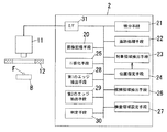
An object B formed of a light transmissive material is imaged by a TV camera 11. The first edge extraction unit 28 uses a threshold value that can extract the contours of the foreign matter F embedded in the article B and the foreign matter F exposed on the surface of the article B with respect to the grayscale image. Edges are extracted from the binarized image. The second edge extraction means 29 is set so that the contour line of the foreign matter F exposed on the surface of the article B is extracted from the differential image and the contour line of the foreign matter F embedded in the article B is not extracted. Edges are extracted from pixels above the threshold. The determination unit 30 is configured to remove foreign matter F in the article B when the rate of change in edge length extracted by the first edge extraction unit 28 and the second edge extraction unit 29 is equal to or less than a predetermined determination threshold. Judged to be adhered.
[Selection] Figure 1
Description
本発明は、光透過性の材料により形成された物品に付着した異物が除去可能な異物か否かを判断する画像処理による外観検査方法およびその装置に関するものである。 The present invention relates to an appearance inspection method by image processing for determining whether or not a foreign matter attached to an article formed of a light-transmitting material is a removable foreign matter and an apparatus therefor.
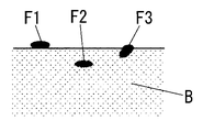
一般に、物品の製造時に物品に付着する異物には、図8のように、物品Bの表面に付着して除去可能な異物F1と、物品Bの内部に埋入されて除去不能な異物F2と、物品Bの内部に一部が埋入されて除去不能な異物F3とがある。以下では、異物F1が物品Bの表面に付着して除去可能である状態を「異物付着」、異物F2の全体が物品Bに埋入されて除去不能な状態を「異物混入」、異物F3の一部が物品Bに埋入されて除去不能な状態を「異物部分混入」と呼ぶ。異物混入や異物部分混入は、異物F2,F3を除去することができず物品Bの品質が損なわれるから、欠陥品として処分することが要求される。 In general, the foreign matter that adheres to the article during the manufacture of the article includes foreign matter F1 that can be removed by attaching to the surface of the article B, and foreign matter F2 that is embedded in the article B and cannot be removed, as shown in FIG. There is a foreign matter F3 that is partially embedded in the article B and cannot be removed. In the following, the state in which the foreign matter F1 adheres to the surface of the article B and can be removed is “foreign matter adhesion”, the state in which the entire foreign matter F2 is embedded in the article B and cannot be removed is “foreign matter mixed”, and the foreign matter F3 A state in which a part is embedded in the article B and cannot be removed is referred to as “foreign matter partial mixing”. Foreign matter contamination and foreign matter partial contamination cannot be removed from the foreign matters F2 and F3, and the quality of the article B is impaired. Therefore, disposal as a defective product is required.
一方、異物付着の場合にはブラシやエアブローによって異物F1を簡単に除去することができるから、欠陥品と誤認されないように欠陥品とは区別する必要がある。異物付着を異物混入と誤認すれば、良品を欠陥品と判断して処分してしまういわゆる無駄ばねが生じて歩留まりが低下する。 On the other hand, in the case of foreign matter adhesion, the foreign matter F1 can be easily removed by a brush or air blow, so it is necessary to distinguish it from a defective product so that it is not mistaken for a defective product. If it is mistaken that foreign matter is adhering to foreign matter, a so-called useless spring is generated in which a non-defective product is judged as a defective product and disposed, and the yield decreases.
物品Bの外観を撮像した濃淡画像を用いて異物の有無を判断する方法としては、検査領域内の画素の微分値を求め、微分値の平均値(平均微分値)と適宜の閾値との大小を比較し、平均微分値が閾値よりも大きいときに異物が存在すると判断する技術が知られている(たとえば、特許文献1参照)。 As a method of determining the presence or absence of a foreign substance using a grayscale image obtained by imaging the appearance of the article B, a differential value of a pixel in an inspection region is obtained, and the difference between the average value of the differential value (average differential value) and an appropriate threshold value is determined. Is known, and when the average differential value is larger than a threshold value, it is determined that a foreign substance exists (see, for example, Patent Document 1).
特許文献1に記載の技術では、異物と刻印とを区別するために、平均微分値に適用する閾値を2段階に設定しており、平均微分値が小さいほうの閾値以下であるときには異物が存在しないと判断し、平均微分値が大きいほうの閾値よりも大きいときには異物が存在すると判断し、平均微分値が両閾値の間であれば異物と刻印とのいずれかが存在すると判断している。
特許文献1に記載の技術を採用すると、撮像した濃淡画像に含まれる情報を用いて物品に異物が付着しているか否かを判断することができる。しかしながら、光透過材料により形成された物品では、物品内に埋入された部分が画像内に含まれるから、異物混入あるいは異物部分混入と、異物付着とを区別することができない。その結果、異物を簡単に除去できるにもかかわらず欠陥品と誤認することによる無駄ばねを防止することができない。
When the technique described in
本発明は上記事由に鑑みて為されたものであり、その目的は、光透過性の材料により形成された物品において、異物の全体または一部が埋入されているか異物が表面に付着しているかを判別することを可能にした画像処理による外観検査方法およびその装置を提供することにある。 The present invention has been made in view of the above-mentioned reasons, and the object thereof is that an article formed of a light-transmitting material has the whole or part of the foreign matter embedded therein or the foreign matter adheres to the surface. It is an object of the present invention to provide an appearance inspection method by image processing and an apparatus thereof that make it possible to discriminate whether or not.
請求項1の発明は、光透過性の材料により形成された物品を撮像手段により撮像し、撮像により得られた濃淡画像を用いて異物を判別する外観検査方法であって、濃淡画像に対して物品の内部に埋入された異物と物品の表面に露出する異物との輪郭が併せて抽出可能となるように設定した閾値を用いて二値化した二値画像からエッジを抽出する第1のエッジ抽出処理と、濃淡画像を微分した微分画像に対して物品の表面に露出する異物の輪郭線が抽出され物品の内部に埋入された異物の輪郭線が抽出されないように設定した閾値以上の画素からエッジを抽出する第2のエッジ抽出処理とを行い、第1のエッジ抽出処理により抽出したエッジの長さと第2のエッジ抽出処理により抽出したエッジの長さとの変化が規定した判定閾値以下であるときに除去可能な異物と判定することを特徴とする。
The invention of
請求項2の発明では、請求項1の発明において、前記第1のエッジ抽出処理は、前記二値画像において前記異物に相当する画素値を有する画素からなる連結領域の各画素のうち、4近傍となる4個の画素のうちのいずれかが異なる画素値を持つ画素を第1のエッジ抽出処理によるエッジ上の画素として抽出することを特徴とする。 According to a second aspect of the present invention, in the first aspect of the invention, the first edge extraction processing is performed in four neighborhoods of the pixels in the connected region composed of pixels having pixel values corresponding to the foreign matter in the binary image. A pixel having a different pixel value from any of the four pixels is extracted as a pixel on the edge by the first edge extraction process.
請求項3の発明では、請求項1または請求項2の発明において、前記第2のエッジ抽出処理は、前記第1のエッジ抽出処理により抽出したエッジ上の各画素の8近傍となる8個の画素の中に、前記微分画像から抽出した前記閾値以上の画素が存在するときに前記第1のエッジ抽出処理により抽出した画素を第2のエッジ抽出処理によるエッジ上の画素として抽出することを特徴とする。 According to a third aspect of the present invention, in the first or second aspect of the invention, the second edge extraction processing is performed in eight neighborhoods of eight pixels on the edge extracted by the first edge extraction processing. A pixel extracted by the first edge extraction process is extracted as a pixel on an edge by the second edge extraction process when a pixel having a threshold value or more extracted from the differential image exists among the pixels. And
請求項4の発明では、請求項1ないし請求項3のいずれかの発明において、撮像により得られた濃淡画像を二値化した二値画像から前記異物に相当する画素値を有する画素からなる連結領域を異物の存在する候補領域とし、候補領域を囲むように設定した領域を、前記第1のエッジ抽出処理および前記第2のエッジ抽出処理を行う検査領域とすることを特徴とする。 According to a fourth aspect of the present invention, in any one of the first to third aspects, a connection comprising pixels having pixel values corresponding to the foreign matter from a binary image obtained by binarizing a grayscale image obtained by imaging. The region is a candidate region where a foreign substance exists, and the region set so as to surround the candidate region is set as an inspection region for performing the first edge extraction process and the second edge extraction process.
請求項5の発明では、請求項1ないし請求項4のいずれかの発明において、撮像により得られた濃淡画像のうち前記物品の輪郭線を含むようにあらかじめ設定した着目領域の画素について濃度勾配の方向に方向値を対応付けた微分方向画像を生成し、方向値を用いて画素を追跡することにより求められる前記物品の輪郭線に対する近似線を設定し、着目領域のうち近似線に対して物品内の領域を異物の候補を抽出する処理対象領域とすることを特徴とする。 According to a fifth aspect of the present invention, in any one of the first to fourth aspects of the present invention, the density gradient of the pixel of the region of interest set in advance so as to include the contour line of the article in the grayscale image obtained by imaging. A differential direction image in which a direction value is associated with a direction is generated, an approximation line is set for the outline of the article obtained by tracking pixels using the direction value, and the article is set for the approximation line in the region of interest. This region is a processing target region from which foreign substance candidates are extracted.
請求項6の発明では、請求項5の発明において、前記近似線は、画素の追跡により検出された前記物品の輪郭線に対して指定された画素数分だけ物品の内側に離れて設定されることを特徴とする。 According to a sixth aspect of the invention, in the fifth aspect of the invention, the approximate line is set apart from the inside of the article by the number of pixels specified with respect to the outline of the article detected by pixel tracking. It is characterized by that.
請求項7の発明は、光透過性の材料により形成された物品を撮像する撮像手段と、撮像により得られた濃淡画像を二値化した二値画像を生成する二値化手段と、二値画像から異物に相当する画素値を有する画素からなる連結領域を抽出して異物の存在する候補領域として抽出する候補領域抽出手段と、候補領域を囲む領域を検査領域として設定する検査領域設定手段と、検査領域内の濃淡画像を微分した微分画像を生成する微分手段と、二値化手段により得られた二値画像において異物に相当する画素値を有する画素からなる連結領域の各画素のうち、4近傍となる4個の画素のうちのいずれかが異なる画素値を持つ画素をエッジ上の画素として抽出する第1のエッジ抽出手段と、第1のエッジ抽出手段により抽出したエッジ上の各画素の8近傍となる8個の画素の中に微分手段により得られた微分画像に対して物品の表面に露出する異物の輪郭線が抽出され物品の内部に埋入された異物の輪郭線が抽出されないように設定した閾値以上の画素が存在するときに第1のエッジ抽出手段により抽出した画素をエッジ上の画素として抽出する第2のエッジ抽出手段と、第1のエッジ抽出手段により抽出したエッジの長さと第2のエッジ抽出手段により抽出したエッジの長さとの変化が規定した判定閾値以下であるときに除去可能な異物と判定する判定手段とを備えることを特徴とする。
The invention of
請求項1の発明の構成によれば、物品の内部に埋入された異物と物品の表面に露出する異物との輪郭線が併せて抽出可能となるように濃淡画像を二値化した二値画像を用いてエッジを抽出する第1のエッジ抽出処理と、物品の表面に露出する異物の輪郭線が抽出され物品の内部に埋入された異物の輪郭線が抽出されないように微分値に対して規定した閾値以上である画素からエッジを抽出する第2のエッジ抽出処理とを採用しているから、第1のエッジ抽出処理では異物の全体または一部が物品に埋入されている異物混入あるいは異物部分混入か表面に付着している異物付着かにかかわらず異物の輪郭線の大部分を含むエッジが抽出され、第2のエッジ抽出処理では物品の表面に露出している異物の輪郭線を含むエッジが抽出される。
According to the configuration of the invention of
すなわち、第1のエッジ抽出処理により検出されたエッジと第2のエッジ抽出処理により抽出されたエッジとの長さを比較すれば、異物が物品に埋入されている程度がわかることになる。異物が物品に完全に埋入されているときには、第2のエッジ抽出処理では異物の輪郭に相当するエッジが抽出されず、異物が物品に埋入されずに付着しているときには、第1のエッジ抽出処理と第2のエッジ抽出処理とで得られるエッジの長さの差が小さく、異物の一部が物品に埋入されているときには、第1のエッジ抽出処理と第2のエッジ抽出処理とで得られるエッジの長さの差が大きくなる。 That is, by comparing the lengths of the edges detected by the first edge extraction process and the edges extracted by the second edge extraction process, the extent to which foreign matter is embedded in the article can be understood. When the foreign object is completely embedded in the article, the edge corresponding to the outline of the foreign object is not extracted in the second edge extraction process, and when the foreign object adheres without being embedded in the article, the first When the difference in edge length obtained between the edge extraction process and the second edge extraction process is small and a part of the foreign matter is embedded in the article, the first edge extraction process and the second edge extraction process And the difference in edge lengths obtained by
このような性質を利用することにより、除去可能な異物か否かを画像処理により判断することが可能になり、除去可能な異物が付着しているときに、欠陥品として処理する無駄ばねを防止することができ、結果的に歩留まりの向上につながる。 By using these properties, it is possible to determine whether or not a foreign object is removable by image processing, and it is possible to prevent a waste spring from being processed as a defective product when a removable foreign object is attached. Can result in improved yield.
請求項2の発明の構成によれば、二値画像における連結領域内で各画素の4近傍の画素について異物の内外を判別して輪郭線上のエッジを抽出するから、8近傍の画素について判別することなく同精度で異物の輪郭線となるエッジ上の画素を抽出することができ、結果的に、第1のエッジ抽出処理の処理負荷を少なくし高速な処理が可能になる。 According to the configuration of the second aspect of the present invention, the inside and outside of the foreign matter is discriminated and the edge on the contour line is extracted for the four neighboring pixels of each pixel in the connected region in the binary image, so that the eight neighboring pixels are discriminated. Therefore, it is possible to extract pixels on the edge that is the outline of the foreign substance with the same accuracy, and as a result, the processing load of the first edge extraction process is reduced and high-speed processing is possible.
請求項3の発明の構成によれば、微分画像において閾値以上となる画素が二値画像から抽出したエッジ上の画素の8近傍に存在するときに、二値画像から抽出したエッジ上の画素を第2のエッジ抽出処理により抽出したエッジ上の画素とするから、微分画像の微分値に対して閾値を適用しただけでは幅を持つのに対して、あらかじめ抽出したエッジ上の画素の中から微分値を用いてエッジ上の画素を抽出することで、二値画像から得たエッジと同幅のエッジを抽出することが可能になる。しかも、微分画像を用いる第2のエッジ抽出処理により得られるエッジ上の画素は、二値画像から第1のエッジ抽出処理により得られるエッジ上の画素に含まれるから、エッジ長の変化を判別する際に精度よく比較することができる。 According to the configuration of the invention of claim 3, when pixels that are equal to or greater than the threshold in the differential image are present in the vicinity of 8 pixels on the edge extracted from the binary image, the pixels on the edge extracted from the binary image are Since the pixel on the edge extracted by the second edge extraction process has a width only by applying a threshold value to the differential value of the differential image, the pixel is differentiated from the pixels on the edge extracted in advance. By extracting pixels on the edge using the value, it is possible to extract an edge having the same width as the edge obtained from the binary image. In addition, since the pixel on the edge obtained by the second edge extraction process using the differential image is included in the pixel on the edge obtained by the first edge extraction process from the binary image, the change in the edge length is determined. It is possible to compare with accuracy.
請求項4の発明の構成によれば、異物の存在する候補領域に基づいて、候補領域が含まれる制限された領域に検査領域を設定しているから、異物に関するエッジを抽出する際に照度むらや物品の輪郭線などによるエッジが含まれる可能性を低減でき、異物に関するエッジを抽出する精度が高くなる。しかも、検査領域を狭い範囲に制限するから、処理対象となる画素数が制限され、結果的に処理負荷が軽減され処理速度の向上につながる。 According to the configuration of the fourth aspect of the invention, since the inspection area is set in the restricted area including the candidate area based on the candidate area where the foreign substance exists, uneven illuminance is extracted when the edge related to the foreign substance is extracted. And the possibility of including an edge due to an outline of an article can be reduced, and the accuracy of extracting an edge related to a foreign object is increased. Moreover, since the inspection area is limited to a narrow range, the number of pixels to be processed is limited, resulting in a reduction in processing load and an increase in processing speed.
請求項5の発明の構成によれば、物品の輪郭線に対する近似線を設定し、近似線に対して物品の内側の領域を処理対象領域としているから、物品の輪郭線を異物の輪郭線と誤認するのを防止できる。
According to the configuration of the invention of
請求項6の発明の構成によれば、処理対象領域の境界を決める近似線と物品の輪郭線との距離が指定されるから、画像内で検出される物品の輪郭線に凹凸があっても処理対象領域から物品の輪郭線を除外することができる。つまり、近似線を適宜に指定することにより、対象となる物品の輪郭線形状に応じて適正な処理対象領域を設定することができる。 According to the configuration of the invention of claim 6, since the distance between the approximate line that determines the boundary of the processing target area and the outline of the article is specified, even if the outline of the article detected in the image is uneven The outline of the article can be excluded from the processing target area. In other words, by appropriately specifying the approximate line, it is possible to set an appropriate processing target area according to the outline shape of the target article.
請求項7の発明の構成によれば、請求項1の発明と同様に、異物について物品の表面に露出している部分と物品に埋入されている部分とを判別することができ。したがって、除去可能な異物が物品に付着している場合に欠陥品として処理する無駄ばねを防止することができ、歩留まりの向上につながるという利点がある。また、第2のエッジ抽出手段により抽出されるエッジ上の画素は、第1のエッジ抽出手段により抽出されるエッジ上の画素に含まれるから、判定手段でエッジ長の変化を検出する際に正確な比較が可能になる。さらに、異物の存在する候補領域に基づいて検査領域を候補領域の輪郭付近に制限するから、異物に関するエッジを抽出する際に照度むらや物品の輪郭線などによるエッジが含まれる可能性を低減できるとともに、異物の内側形状についても無視することができ、異物に関するエッジを抽出する精度が高くなる上に、処理対象の画素数が少なく処理負荷の軽減がなされ処理速度の向上につながる。
According to the configuration of the invention of
本実施形態は、図1に示すように、物品Bを撮像する撮像手段としてのTVカメラ11と、物品Bを照明する照明装置12とを備える。照明装置12は、物品Bの表面に陰影が形成されないように無影灯(リング照明)を用いるのが望ましい。物品Bは光透過性材料からなり、透明な合成樹脂成形品に限らず、不透明に着色された合成樹脂成形品であっても表面付近が光透過性を有するものであれば光透過性材料の物品Bに含まれる。たとえば、白色系に着色した合成樹脂成形品は光透過性材料に含まれる。また、合成樹脂材料以外にもガラス材料など光透過性を有する物品Bであれば、本発明の技術思想は適用できる。
As shown in FIG. 1, the present embodiment includes a
TVカメラ11で得られた濃淡画像(明度値を画素値とするデジタル画像)は、画像処理装置2に入力される。画像処理装置2は、画像を取り込むためのインターフェース31および画像記憶用の画像記憶手段20を備え、TVカメラ11からの濃淡画像は画像記憶手段20に一旦格納される。画像記憶手段20は後述する処理で生成される各画像の記憶にも用いられる。画像処理装置2は、コンピュータを主構成とする装置であり、適宜のプログラムを実行することにより、以下の処理を可能にする。
A grayscale image (digital image having a lightness value as a pixel value) obtained by the
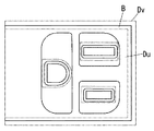
まず、画像記憶手段20に格納された濃淡画像に対して物品Bが含まれる範囲に、図3に示すように、着目領域Dvが設定される。着目領域Dvは、TVカメラ11の視野内において物品Bの少なくとも一部を含んでいればよいが、通常は物品Bの輪郭線を含むように設定される。
First, as shown in FIG. 3, a region of interest Dv is set in a range where the article B is included in the grayscale image stored in the
本実施形態では、製造ラインなどにおいてTVカメラ11に対する物品Bの位置がほぼ決まっていることを利用して、TVカメラ11の視野内において着目領域Dvを固定的に設定できる場合を想定する。なお、濃淡画像を適宜の閾値で二値化することにより物品Bと背景とを分離することにより、着目領域Dvを物品Bを含む領域として自動的に抽出するようにすることも可能である。また、単品の物品Bであれば、濃淡画像をモニタ装置の画面に表示して人手で着目領域Dvを設定することが可能である。
In the present embodiment, it is assumed that the region of interest Dv can be fixedly set within the field of view of the
着目領域Dvが決まると、着目領域Dvに含まれる画素について微分手段21による方向値の演算を行う。方向値は、濃淡画像における各画素の濃度勾配の方向を量子化した値であり、たとえば45度ずつ8個の方向値を濃度勾配に割り当てる。また、方向値では濃度勾配の方向に直交する方向を0度とし、たとえば、0度を中心とする±22.5度の範囲に対応する方向値を1とし、左回りに45度の範囲ごとに1〜8の数値を方向値として割り当てる。方向値は濃度勾配が閾値以下の画素には付与しない。
When the attention area Dv is determined, the direction value is calculated by the differentiating
次に、追跡処理手段22において、着目領域Dvの中で方向値を用いて画素を追跡する。方向値を用いて画素を追跡するとは、方向値の得られているいずれかの画素を着目画素とし、着目画素の方向値に対して一定範囲(たとえば、±112.5度の範囲)内に±90度に相当する方向値の画素が隣接しているときに、当該画素を次の着目画素として同処理を繰り返すことにより、連続する画素列を抽出することを意味している。この処理により、物品Bの輪郭線上の画素や物品Bに刻印された文字の輪郭線上の画素のように、濃度勾配が閾値以上になる部位の画素列が抽出される。物品Bの外周縁の内側に孔が形成されている場合には、孔の開口周縁も輪郭線になる。 Next, the tracking processing means 22 tracks the pixels using the direction value in the region of interest Dv. Tracking a pixel using a direction value means that any pixel from which the direction value is obtained is a target pixel and is within a certain range (for example, a range of ± 112.5 degrees) with respect to the direction value of the target pixel. This means that when pixels having a direction value corresponding to ± 90 degrees are adjacent to each other, the same process is repeated as the next pixel of interest to extract a continuous pixel row. By this processing, a pixel row of a part where the density gradient is equal to or greater than a threshold value, such as pixels on the outline of the article B and pixels on the outline of the character imprinted on the article B, is extracted. When a hole is formed inside the outer peripheral edge of the article B, the opening peripheral edge of the hole is also a contour line.
方向値を用いて追跡した画素により物品Bなどの輪郭線が抽出されると、対象領域設定手段23において、輪郭線に近似する近似線を求め、さらに輪郭線に対して物品Bの内側となる部位に近似線を設定し、近似線よりも物品Bの内側の領域を処理対象領域Duに定める。近似線は、輪郭線に微小な凹凸があってもこれを無視した直線または曲線として求められる。近似線を直線とすべきか円弧や楕円弧のような曲線とすべきかは、輪郭線上の画素の方向値の並びにより決定することができる。たとえば、同じ方向値が規定個数以上含まれていれば直線、画素の並び順で方向値が順に変化する傾向があれば曲線とする。
When a contour line such as the article B is extracted by the pixel tracked using the direction value, the target
対象領域設定手段23には、位置指定手段24が付設されており、求めた近似線の輪郭線に対する位置を画素数で設定できるようにしてある。近似線は輪郭線に対して指定した画素数分だけ物品Bの内側に設定される。物品Bに孔が形成されている場合には孔の開口周縁から物品B側に離れて近似線が設定される。このようにして設定された近似線に囲まれた領域が処理対象領域Duになる。図3から明らかなように、物品Bにおいて輪郭線が存在しない箇所では、処理対象領域Duの境界と着目領域Dvの境界とが一致する。 The target area setting means 23 is provided with a position specifying means 24 so that the position of the obtained approximate line relative to the contour line can be set by the number of pixels. The approximate line is set inside the article B by the number of pixels specified for the contour line. When a hole is formed in the article B, an approximate line is set away from the opening periphery of the hole toward the article B. The region surrounded by the approximate line set in this way is the processing target region Du. As is clear from FIG. 3, the boundary of the processing target area Du and the boundary of the attention area Dv coincide with each other in the part where no outline exists in the article B.
画像処理装置2は、処理対象領域Duが設定されると、濃淡画像を適宜の閾値により二値化した二値画像から異物が存在する可能性のある領域を候補領域として抽出し、候補領域が存在する場合には、候補領域を囲むように検査領域を設定する。
When the processing target region Du is set, the
二値画像は、二値化手段25が画像記憶手段20に格納された濃淡画像を読み出し、この濃淡画像に適宜の閾値を適用して二値化することにより得られる。二値化手段25に設定される閾値は、異物Fが物品Bに埋入されているか付着しているかにかかわらず、異物の存在範囲を抽出することができるように設定される。すなわち、物品Bと異物Fとの反射率および透過率の相違に起因した濃淡画像内での明度の差を利用して物品Bと異物Fとを区別する。
The binary image is obtained by the
異物Fは画像内である程度の大きさを有しているから、候補領域抽出手段26において、連結領域(ここでは、二値画像において各画素に隣接する画素が異物Fに相当する画素値を有する画素の集合)の画素数を評価し、画素数が規定条件を満たすときに、当該連結領域を異物Fが存在する候補領域とみなす。画素数に対する条件は、規定した閾値以上であるときに異物Fの可能性があると判断する。
Since the foreign substance F has a certain size in the image, the candidate
ただし、候補領域抽出手段26では、上記条件を満たす連結領域(候補領域)であっても、以下のいずれかの条件が成立するときには、検査領域を設定せずに欠陥品と判断する。すなわち、候補領域の個数が閾値以上であるか、いずれかの候補領域の画素数が上述の閾値よりも大きい上限値を超えるか、すべての候補領域の画素数の総和が規定した閾値を超えるときには、過剰な汚れで異物Fの量が多すぎる欠陥品と判断する。
However, the candidate
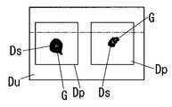
候補領域抽出手段26において、候補領域である連結領域に関して欠陥品ではないと判断されると、検査領域設定手段27において候補領域を囲むように検査領域が設定される。検査領域設定手段27は、図4に示すように、二値化手段25により生成された二値画像を用いて候補領域Dsの重心Gを求め、この重心を中心とする矩形状の領域を検査領域Dpとして設定する。ただし、検査領域Dpにおいて処理対象領域Duの外側となる領域があれば、設定した検査領域Dpのうちで処理対象領域Duの内側となる領域のみを検査領域Dpとして採用する。
When the candidate
設定する検査領域Dpを矩形状の領域とする場合には、候補領域Dsの水平方向(X方向)および垂直方向(Y方向)の幅寸法(画素数)Lx,Lyを求め、各幅寸法Lx,Lyに規定画素数を加算した長さ寸法の辺を持つ長方形(または正方形)を検査領域Dpとする。なお、検査領域Dpは矩形状に限定されるものではなく、幅寸法Lx,Lyに規定画素数を加算した寸法の長径および短径を有する楕円形(または円形)の検査領域Dpを採用することも可能である。 When the inspection region Dp to be set is a rectangular region, the width dimensions (number of pixels) Lx and Ly of the candidate area Ds in the horizontal direction (X direction) and the vertical direction (Y direction) are obtained, and each width dimension Lx , Ly is a rectangular (or square) having a side with a length dimension obtained by adding the specified number of pixels to the inspection area Dp. Note that the inspection region Dp is not limited to a rectangular shape, and an elliptical (or circular) inspection region Dp having a major axis and a minor axis with dimensions obtained by adding a specified number of pixels to the width dimensions Lx and Ly is adopted. Is also possible.
検査領域Dpの設定後には、検査領域Dpの濃淡画像について二値化手段25で二値化を行う。この二値化にあたって用いる閾値は、候補領域Dsを抽出する際の二値化で用いた閾値と等しい値を用いることができる。したがって、あらためて二値化を行わずに先の二値化により得られた二値画像のうち検査領域Dp内の部位を用いてもよい。 After the inspection area Dp is set, the binarization means 25 binarizes the grayscale image in the inspection area Dp. As the threshold used for binarization, a value equal to the threshold used for binarization when extracting the candidate region Ds can be used. Therefore, a part in the examination region Dp may be used in the binary image obtained by the previous binarization without performing binarization again.
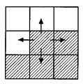
検査領域Dpの二値画像が得られると、第1のエッジ抽出手段28において、検査領域Dp内の二値画像から異物Fの輪郭線となるエッジが抽出される。この処理では、図5に示すように、二値化により異物Fの存在領域と判断された連結領域(つまり、候補領域Ds)の各画素について、4近傍の画素(垂直方向または水平方向に隣接する4個の画素)の画素値を取り出し、4近傍の画素のいずれかの画素値が着目画素の画素値と異なっている場合に、着目画素を異物Fの輪郭線に相当するエッジ上の画素として抽出する。たとえば、異物Fに対応する領域の画素が黒画素であるときに、4近傍に白画素が存在すると、当該黒画素を異物Fの輪郭線に相当するエッジ上の画素とする。図示例(升目は画素を意味する)では、中央の画素が着目画素であり、4近傍のうちの上と左とに着目画素とは異なる画素値の画素が存在するから、着目画素はエッジ上の画素と判断される。
When a binary image of the inspection region Dp is obtained, the first
第1のエッジ抽出手段28により抽出されるエッジ上の画素は、異物Fが異物付着か異物混入か異物部分混入かにかかわらず、異物Fの略全周についてエッジ上の画素を抽出する。
The pixels on the edge extracted by the first
画像処理装置2は、異物Fにおいて物品Bから露出している部位のエッジ上の画素を抽出し物品Bに埋入されている部位の画素は抽出しない第2のエッジ抽出手段29も備えている。第2のエッジ抽出手段29では検査領域Dpの濃淡画像から微分手段21で生成した微分画像を用い、以下の処理によってエッジ上の画素を抽出する。ここに、微分画像を求める範囲を検査領域Dpに制限しているから、微分処理に要する処理負荷が小さく高速な処理が期待できる。
The
第2のエッジ抽出手段29は、第1のエッジ抽出手段28により抽出したエッジ上の画素の8近傍の画素(着目画素に隣接する8個の画素)の中に微分値(微分画像の画素値)が規定の閾値以上のものがあれば、当該画素を第2のエッジ抽出手段29により抽出したエッジ上の画素とする。微分値に対する閾値は、異物Fにおいて物品Bに埋入されている部位を抽出しない程度に設定する。つまり、異物Fにおいて物品Bから露出している部位の微分値の極大値付近で数画素程度が抽出されるように閾値を設定すればよい。
The second
第2のエッジ抽出手段29により抽出されるエッジ上の画素は、第1のエッジ抽出手段28により抽出されるエッジ上の画素のうちで、8近傍の画素が上記条件を満たす画素であるから、第1のエッジ抽出手段28により抽出された画素の一部または全部になる。 Since the pixels on the edge extracted by the second edge extracting means 29 are pixels on the edge extracted by the first edge extracting means 28, the pixels in the vicinity of 8 are pixels satisfying the above condition. Some or all of the pixels extracted by the first edge extraction means 28 are used.
いま、図5の各升目を画素として黒塗りの画素が第1のエッジ抽出手段28により抽出された画素のうちの着目画素であるとする。第2のエッジ抽出手段29は、着目画素の8近傍の画素について微分値が閾値以上の画素が存在するか否かを判断する。図示例では、微分値が閾値以上である画素に斜線を施してあり、着目画素の8近傍の画素のうち3個の画素が条件を満たしていることになる。したがって、着目画素は第2のエッジ抽出手段29で抽出される画素になる。
Now, assume that each pixel in FIG. 5 is a pixel of interest among the pixels extracted by the first
上述したように、第1のエッジ抽出手段28では、物品Bに埋入されているか否かにかかわらず異物Fの輪郭線に相当するエッジ上の画素が抽出され、第2のエッジ抽出手段29では、物品Bの表面に露出する異物Fの輪郭線に相当するエッジのみを抽出することができる。したがって、異物付着では両エッジ抽出手段28,29でともにエッジが抽出され、異物混入では第1のエッジ抽出手段28でエッジが抽出されるが第2のエッジ抽出手段29ではエッジが抽出されないことになる。
As described above, the first
ところで、異物部分混入の場合には、異物付着の場合と同様に、両エッジ抽出手段28,29でともにエッジが抽出される。ただし、異物部分混入では、異物Fの一部が物品Bの表面に露出し、一部が物品Bの内部に埋入されているから、第1のエッジ抽出手段28で抽出したエッジの長さに対して、第2のエッジ抽出手段29で抽出したエッジの長さが短くなる。
By the way, in the case of foreign matter part mixing, the edges are extracted by both
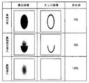
異物付着、異物部分混入、異物混入の各場合について、濃淡画像と第2のエッジ抽出手段29により抽出したエッジ上の画素を表すエッジ画像とを並記して図6に示す。エッジ画像ではエッジが白画素になるが、図6では実際の画像とは白黒を反転させて表記している。また、図6には第1のエッジ抽出手段28により抽出したエッジ上の画素と、第2のエッジ抽出手段29により抽出したエッジ上の画素との画素数の変化率を表記している。変化率ηは、第1のエッジ抽出手段28で得られる画素数をn1、第2のエッジ抽出手段29で得られる画素数をn2とすれば、η={(n1−n2)/n1}×100%で表すことができる。
FIG. 6 shows a grayscale image and an edge image representing pixels on the edge extracted by the second edge extraction means 29 for each case of foreign matter adhesion, foreign matter partial contamination, and foreign matter contamination. In the edge image, the edge is a white pixel, but in FIG. 6, the actual image is represented by reversing black and white. FIG. 6 shows the rate of change in the number of pixels between the pixel on the edge extracted by the first
異物付着の場合には画素数の変化は少なく変化率は高々10%程度であり、異物部分混入の場合には異物Fが物品Bに埋入されている部位の割合にもよるが変化率は50%前後(たとえば、20〜80%)になることが多い。また、異物混入の場合には異物Fが物品Bに完全に埋入されているから変化率は100%になる。 In the case of foreign matter adhesion, the change in the number of pixels is small and the rate of change is about 10% at most. In the case of foreign matter part mixing, the rate of change depends on the proportion of the part where the foreign matter F is embedded in the article B. Often around 50% (for example, 20-80%). Further, in the case of contamination, the change rate is 100% because the foreign matter F is completely embedded in the article B.
このように、異物付着か異物部分混入か異物混入かは第1のエッジ抽出手段28で抽出したエッジと第2のエッジ抽出手段29で抽出したエッジとのエッジ長の変化の程度により判別することができる。画像処理装置2には、エッジ長の変化により異物付着か異物部分混入か異物混入かを判別する判定手段30が設けられる。判定手段30では、変化率ηが判定閾値以下であれば異物付着と判断し、判定閾値以上であるときには異物部分混入または異物混入であるから欠陥品と判断する。なお、上述の動作例では、判定手段30においてエッジ長の変化を変化率として求めているが、エッジ長の比率やエッジ長の差分を用いてもよい。
In this way, whether foreign matter is attached, foreign matter part or foreign matter is determined by the degree of change in the edge length between the edge extracted by the first
本実施形態の動作を図2にまとめる。まず、撮像手段であるTVカメラ11により撮像された濃淡画像を画像記憶手段20に格納し、着目領域Dvを設定する(S1)。次に、着目領域Dvを設定し(S2)、微分手段21により着目領域Dvの中で方向値を求め、物品Bの輪郭線を抽出する(S3)。物品Bの輪郭線が濃淡画像から抽出されると、輪郭線に対して指定画素分だけ近似線を変位させて処理対象領域Duを設定する(S4)。
The operation of this embodiment is summarized in FIG. First, the grayscale image imaged by the
処理対象領域Duの中の濃淡画像は二値化され(S5)、二値画像内の連結領域が求められるとともに、その画素数が求められる(S6)。ここで、連結領域の画素数が閾値Th1よりも小さいときには異物Fが存在していないと言えるから、異物Fに関して良品の判断がなされる(S7)。この処理は処理対象領域Duに存在するすべての連結領域について行われる(S8)。 The grayscale image in the processing target area Du is binarized (S5), and a connected area in the binary image is obtained and the number of pixels is obtained (S6). Here, when the number of pixels in the connected area is smaller than the threshold value Th1, it can be said that the foreign matter F does not exist, and therefore, the non-defective product is determined for the foreign matter F (S7). This process is performed for all connected areas existing in the processing target area Du (S8).
ここで、連結領域の個数が規定の閾値Th2以上であるか、いずれかの連結領域の画素数が規定の閾値Th3以上であるか(Th3>Th1)、処理対象領域Duに存在するすべての連結領域の画素数の総和が規定の閾値Th4以上である場合には(S9)、物品Bに多数の異物Fが存在しており、異物付着、異物部分混入、異物混入の判断に適さない欠陥品と判断する。つまり、上述の3条件のいずれかが満たされるときには欠陥品と判断する。 Here, whether the number of connected areas is equal to or greater than a prescribed threshold Th2, or whether the number of pixels in any connected area is equal to or greater than the prescribed threshold Th3 (Th3> Th1), all the connections existing in the processing target area Du. If the sum of the number of pixels in the area is equal to or greater than the prescribed threshold Th4 (S9), there are many foreign substances F in the article B, and the defective article is not suitable for the determination of foreign matter adhesion, foreign matter partial contamination, and foreign matter contamination. Judge. That is, if any of the above three conditions is satisfied, it is determined as a defective product.
連結領域の画素数が閾値Th1以上であり、かつ欠陥品ではないと判断されると、当該連結領域を候補領域Dsとし、候補領域Dsを囲む検査領域Dpを設定する(S10)。検査領域Dpの設定後には、検査領域Dpの中の画素について二値化を行って(S11)、二値画像から候補領域Dsの輪郭線に相当するエッジ上の画素を抽出する(S12)。さらに、検査領域Dpの範囲で微分画像を生成し(S13)、ステップS12において求めたエッジ上の画素のうち、8近傍の画素の微分値が閾値以上である画素を抽出する(S14)。 If it is determined that the number of pixels in the connected area is equal to or greater than the threshold Th1 and is not defective, the connected area is set as a candidate area Ds, and an inspection area Dp surrounding the candidate area Ds is set (S10). After the inspection area Dp is set, the pixels in the inspection area Dp are binarized (S11), and the pixels on the edge corresponding to the contour line of the candidate area Ds are extracted from the binary image (S12). Further, a differential image is generated in the range of the inspection area Dp (S13), and among the pixels on the edge obtained in step S12, pixels whose differential values of 8 neighboring pixels are equal to or greater than the threshold are extracted (S14).
ステップS12とステップS14とで求めたエッジ上の画素は、画素数の変化率が求められ(S15)、変化率が判定閾値Th5以下であるときには異物付着と判断する(S16)。なお、判定手段30では、変化率の範囲に応じて異物付着、異物部分混入、異物混入の別を判別してもよい。
For the pixels on the edge obtained in steps S12 and S14, the rate of change in the number of pixels is obtained (S15), and when the rate of change is equal to or less than the determination threshold Th5, it is determined that foreign matter is attached (S16). Note that the
上述のように、異物部分混入および異物混入と異物付着とを画像処理によって区別することが可能になったことにより、除去可能な異物Fが物品Bに付着している異物付着を欠陥品として処理する無駄ばねを防止することができ、歩留まりの向上につながる。なお、検査領域Dpは上述のように候補領域Dsを基準として設定するのが望ましいが、候補領域Dsを含んでいればより広い領域を検査領域Dpに用いることも可能である。 As described above, it is possible to discriminate foreign matter mixing and foreign matter adhering from foreign matter adhering by image processing, so that the foreign matter adhering to the article B with the removable foreign matter F is treated as a defective product. It is possible to prevent the useless spring, which leads to an improvement in yield. The inspection region Dp is desirably set with the candidate region Ds as a reference as described above, but a wider region can be used as the inspection region Dp as long as the candidate region Ds is included.
11 TVカメラ(撮像手段)
12 照明装置
20 画像記憶手段
21 微分手段
22 追跡処理手段
23 対象領域抽出手段
24 位置指定手段
25 二値化手段
26 候補領域抽出手段
27 検査領域設定手段
28 第1のエッジ抽出手段
29 第2のエッジ抽出手段
30 判定手段
B 物品
Dp 検査領域
Ds 候補領域
Du 処理対象領域
Dv 着目領域
F 異物
G 重心
11 TV camera (imaging means)
DESCRIPTION OF
Claims (7)
Priority Applications (1)
| Application Number | Priority Date | Filing Date | Title |
|---|---|---|---|
| JP2007170898A JP5390755B2 (en) | 2007-06-28 | 2007-06-28 | Appearance inspection method and apparatus using image processing |
Applications Claiming Priority (1)
| Application Number | Priority Date | Filing Date | Title |
|---|---|---|---|
| JP2007170898A JP5390755B2 (en) | 2007-06-28 | 2007-06-28 | Appearance inspection method and apparatus using image processing |
Publications (2)
| Publication Number | Publication Date |
|---|---|
| JP2009008564A true JP2009008564A (en) | 2009-01-15 |
| JP5390755B2 JP5390755B2 (en) | 2014-01-15 |
Family
ID=40323787
Family Applications (1)
| Application Number | Title | Priority Date | Filing Date |
|---|---|---|---|
| JP2007170898A Active JP5390755B2 (en) | 2007-06-28 | 2007-06-28 | Appearance inspection method and apparatus using image processing |
Country Status (1)
| Country | Link |
|---|---|
| JP (1) | JP5390755B2 (en) |
Cited By (6)
| Publication number | Priority date | Publication date | Assignee | Title |
|---|---|---|---|---|
| JP2010197176A (en) * | 2009-02-24 | 2010-09-09 | Panasonic Electric Works Co Ltd | Method and device for inspecting defect |
| JP2013529166A (en) * | 2010-04-21 | 2013-07-18 | エルジー・ケム・リミテッド | Glass sheet cutting device |
| KR20210084545A (en) * | 2019-03-04 | 2021-07-07 | 시케이디 가부시키가이샤 | Inspection device, blister packing machine and manufacturing method of blister pack |
| JP2021110629A (en) * | 2020-01-09 | 2021-08-02 | 株式会社小糸製作所 | Inspection device and method for inspection |
| CN119273680A (en) * | 2024-12-06 | 2025-01-07 | 浙江宏奔电气有限公司 | Assembly quality inspection method, device and system for fuse protection box |
| US12430763B2 (en) | 2021-02-15 | 2025-09-30 | Terumo Kabushiki Kaisha | Coating layer inspection device and method for inspecting coating layer |
Citations (7)
| Publication number | Priority date | Publication date | Assignee | Title |
|---|---|---|---|---|
| JPH04350546A (en) * | 1991-05-28 | 1992-12-04 | Matsushita Electric Works Ltd | Detection of foreign matter |
| JPH0815174A (en) * | 1995-06-26 | 1996-01-19 | Matsushita Electric Works Ltd | Defect inspection method by visual inspection |
| JPH1115975A (en) * | 1997-06-25 | 1999-01-22 | Matsushita Electric Works Ltd | Appearance inspecting method |
| JPH1164236A (en) * | 1997-08-19 | 1999-03-05 | Kobe Steel Ltd | Defect detection method and device, and recording medium recording defect detection control program |
| JP3494006B2 (en) * | 1998-04-23 | 2004-02-03 | 松下電工株式会社 | Appearance inspection method |
| JP2004219122A (en) * | 2003-01-10 | 2004-08-05 | Dainippon Printing Co Ltd | Inspection apparatus and inspection method for foreign matter defect |
| JP2006201135A (en) * | 2005-01-24 | 2006-08-03 | Nikon Corp | Defect inspection apparatus, defect inspection method, and defect inspection program |
-
2007
- 2007-06-28 JP JP2007170898A patent/JP5390755B2/en active Active
Patent Citations (7)
| Publication number | Priority date | Publication date | Assignee | Title |
|---|---|---|---|---|
| JPH04350546A (en) * | 1991-05-28 | 1992-12-04 | Matsushita Electric Works Ltd | Detection of foreign matter |
| JPH0815174A (en) * | 1995-06-26 | 1996-01-19 | Matsushita Electric Works Ltd | Defect inspection method by visual inspection |
| JPH1115975A (en) * | 1997-06-25 | 1999-01-22 | Matsushita Electric Works Ltd | Appearance inspecting method |
| JPH1164236A (en) * | 1997-08-19 | 1999-03-05 | Kobe Steel Ltd | Defect detection method and device, and recording medium recording defect detection control program |
| JP3494006B2 (en) * | 1998-04-23 | 2004-02-03 | 松下電工株式会社 | Appearance inspection method |
| JP2004219122A (en) * | 2003-01-10 | 2004-08-05 | Dainippon Printing Co Ltd | Inspection apparatus and inspection method for foreign matter defect |
| JP2006201135A (en) * | 2005-01-24 | 2006-08-03 | Nikon Corp | Defect inspection apparatus, defect inspection method, and defect inspection program |
Non-Patent Citations (3)
| Title |
|---|
| CSNH200700129004; 上ミ 弘高 Hirotaka Uemi: '生産技術 Production Engineering' 松下電工技報 Vol.55 No.2 Technical Report 第55巻, 松下電工株式会社 Matsushita Electric Works,Ltd. * |
| JPN6012018261; 上ミ 弘高 Hirotaka Uemi: '生産技術 Production Engineering' 松下電工技報 Vol.55 No.2 Technical Report 第55巻, 松下電工株式会社 Matsushita Electric Works,Ltd. * |
| JPN6013045877; 井上敏範,白澤満,大塚倫生: '"電気部品製造ラインにおける画像処理技術"' 自動化技術 第27巻、第8号, 19950801, p.53-57, 株式会社工業調査会 * |
Cited By (10)
| Publication number | Priority date | Publication date | Assignee | Title |
|---|---|---|---|---|
| JP2010197176A (en) * | 2009-02-24 | 2010-09-09 | Panasonic Electric Works Co Ltd | Method and device for inspecting defect |
| JP2013529166A (en) * | 2010-04-21 | 2013-07-18 | エルジー・ケム・リミテッド | Glass sheet cutting device |
| US8821211B2 (en) | 2010-04-21 | 2014-09-02 | Lg Chem, Ltd. | Device for cutting of glass sheet |
| US9327381B2 (en) | 2010-04-21 | 2016-05-03 | Lg Chem, Ltd. | Device for cutting of glass sheet |
| KR20210084545A (en) * | 2019-03-04 | 2021-07-07 | 시케이디 가부시키가이샤 | Inspection device, blister packing machine and manufacturing method of blister pack |
| KR102547732B1 (en) | 2019-03-04 | 2023-06-23 | 시케이디 가부시키가이샤 | Manufacturing method of inspection device, blister packaging machine and blister pack |
| JP2021110629A (en) * | 2020-01-09 | 2021-08-02 | 株式会社小糸製作所 | Inspection device and method for inspection |
| JP7546356B2 (en) | 2020-01-09 | 2024-09-06 | 株式会社小糸製作所 | Inspection device and inspection method |
| US12430763B2 (en) | 2021-02-15 | 2025-09-30 | Terumo Kabushiki Kaisha | Coating layer inspection device and method for inspecting coating layer |
| CN119273680A (en) * | 2024-12-06 | 2025-01-07 | 浙江宏奔电气有限公司 | Assembly quality inspection method, device and system for fuse protection box |
Also Published As
| Publication number | Publication date |
|---|---|
| JP5390755B2 (en) | 2014-01-15 |
Similar Documents
| Publication | Publication Date | Title |
|---|---|---|
| JP5351673B2 (en) | Appearance inspection device, appearance inspection method | |
| CN105334219B (en) | A kind of bottle mouth defect detection method of residual analysis dynamic threshold segmentation | |
| CN105139386B (en) | A kind of image processing method of fast automatic detecting electric connector solder joint defective work | |
| WO2017141611A1 (en) | Defect detection apparatus, defect detection method, and program | |
| CN104792794A (en) | Machine vision based optical film surface defect detecting method | |
| JP5390755B2 (en) | Appearance inspection method and apparatus using image processing | |
| CN104700112B (en) | Parasite egg detecting method in a kind of excrement based on morphological feature | |
| CN114018946B (en) | A detection method for highly reflective bottle cap defects based on OpenCV | |
| JP2004354100A (en) | Method and apparatus for detecting foreign matter in liquid within container | |
| US20120207379A1 (en) | Image Inspection Apparatus, Image Inspection Method, And Computer Program | |
| CN110288561A (en) | Scratch recognition method on refractory brick surface based on frequency domain filter enhancement | |
| CN114705696A (en) | Defect detection method based on digital image processing and automatic optical detection | |
| JP2019200775A (en) | Surface defect inspection device and surface defect inspection method | |
| CN102834704A (en) | Inspection of defects in contact lens | |
| JP2017166957A (en) | Defect detection device, defect detection method and program | |
| Duong et al. | Vision inspection system for pharmaceuticals | |
| JP2001034762A (en) | Method and device for image processing checking | |
| JP4336755B2 (en) | A signboard recognition method using color images | |
| JP6688629B2 (en) | Defect detecting device, defect detecting method and program | |
| CN105092589A (en) | Detection method for defects of capsule head | |
| KR101675532B1 (en) | Apparatus and Method for detecting defect of thick steel plate | |
| JP2017166956A (en) | Defect detection device detection method and program | |
| CN109934817B (en) | A detection method for fruit body external contour deformity | |
| JP2005241304A (en) | Appearance inspection method | |
| JPH03175343A (en) | Method for extracting flaw by inspection appearance |
Legal Events
| Date | Code | Title | Description |
|---|---|---|---|
| A621 | Written request for application examination |
Free format text: JAPANESE INTERMEDIATE CODE: A621 Effective date: 20100217 |
|
| RD04 | Notification of resignation of power of attorney |
Free format text: JAPANESE INTERMEDIATE CODE: A7424 Effective date: 20101021 |
|
| A711 | Notification of change in applicant |
Free format text: JAPANESE INTERMEDIATE CODE: A712 Effective date: 20120112 |
|
| A977 | Report on retrieval |
Free format text: JAPANESE INTERMEDIATE CODE: A971007 Effective date: 20120223 |
|
| A131 | Notification of reasons for refusal |
Free format text: JAPANESE INTERMEDIATE CODE: A131 Effective date: 20120410 |
|
| A521 | Written amendment |
Free format text: JAPANESE INTERMEDIATE CODE: A523 Effective date: 20120611 |
|
| A131 | Notification of reasons for refusal |
Free format text: JAPANESE INTERMEDIATE CODE: A131 Effective date: 20121204 |
|
| TRDD | Decision of grant or rejection written | ||
| A01 | Written decision to grant a patent or to grant a registration (utility model) |
Free format text: JAPANESE INTERMEDIATE CODE: A01 Effective date: 20130917 |
|
| A61 | First payment of annual fees (during grant procedure) |
Free format text: JAPANESE INTERMEDIATE CODE: A61 Effective date: 20131011 |
|
| R150 | Certificate of patent or registration of utility model |
Ref document number: 5390755 Country of ref document: JP Free format text: JAPANESE INTERMEDIATE CODE: R150 Free format text: JAPANESE INTERMEDIATE CODE: R150 |