JP2009008085A - Device for axially retaining blade mounted on turbomachine rotor disk - Google Patents
Device for axially retaining blade mounted on turbomachine rotor disk Download PDFInfo
- Publication number
- JP2009008085A JP2009008085A JP2008166894A JP2008166894A JP2009008085A JP 2009008085 A JP2009008085 A JP 2009008085A JP 2008166894 A JP2008166894 A JP 2008166894A JP 2008166894 A JP2008166894 A JP 2008166894A JP 2009008085 A JP2009008085 A JP 2009008085A
- Authority
- JP
- Japan
- Prior art keywords
- rotor disk
- retaining ring
- disk
- blade root
- support surface
- Prior art date
- Legal status (The legal status is an assumption and is not a legal conclusion. Google has not performed a legal analysis and makes no representation as to the accuracy of the status listed.)
- Granted
Links
Images


Classifications
-
- F—MECHANICAL ENGINEERING; LIGHTING; HEATING; WEAPONS; BLASTING
- F01—MACHINES OR ENGINES IN GENERAL; ENGINE PLANTS IN GENERAL; STEAM ENGINES
- F01D—NON-POSITIVE DISPLACEMENT MACHINES OR ENGINES, e.g. STEAM TURBINES
- F01D5/00—Blades; Blade-carrying members; Heating, heat-insulating, cooling or antivibration means on the blades or the members
- F01D5/30—Fixing blades to rotors; Blade roots ; Blade spacers
- F01D5/3007—Fixing blades to rotors; Blade roots ; Blade spacers of axial insertion type
- F01D5/3015—Fixing blades to rotors; Blade roots ; Blade spacers of axial insertion type with side plates
Abstract
Description
本発明は、低圧タービンの最終段のロータといった、ターボ機械ロータディスクに装着されるブレードを軸方向に保持する装置に関する。 The present invention relates to an apparatus for axially holding a blade mounted on a turbomachine rotor disk, such as a rotor at the last stage of a low pressure turbine.
知られている方式では、ターボ機械の低圧タービンは、静翼と交互に配置される複数段のロータブレードを備える。タービンの各段では、静翼は2つの同心シュラウドに固定され、ロータブレードはブレード根元部によってロータディスクに固定される。タービンのロータディスクのすべては、ボルト結合により互いに固定され、トラニオンによってターボ機械の低圧シャフトに固定される。 In a known manner, a turbomachine low-pressure turbine comprises multiple stages of rotor blades arranged alternately with stationary vanes. At each stage of the turbine, the vanes are fixed to two concentric shrouds and the rotor blades are fixed to the rotor disk by blade roots. All of the turbine rotor disks are secured together by bolted connections and secured to the turbomachine's low pressure shaft by trunnions.
また、このような低圧タービンの最終段のディスクは周辺部に複数の軸方向のスロットを有し、各スロットはスロット内にタービンのロータブレードの1つの根元部を装着していることが知られている。タービンを通過するガスストリームはロータブレード上に軸方向力を加え、そのため保持装置によりブレードの軸方向の移動を防止することが必要である。このような装置の1つは、ディスクおよびブレード根元部の半径方向の支持面に押し付けられる環状の端板を用いてブレード根元部の移動を防止することにあり、端板は環状の保持リングによりこの位置に保持される。例として、EP1180580およびEP1498579を参照できる。これは効果的ではあるが、このような装置は通常、いくつかの部品(特に、端板および端板保持リング)を利用するため、製造および装着が複雑である。 Further, it is known that the final stage disk of such a low-pressure turbine has a plurality of axial slots in the periphery, and each slot has one root part of the turbine rotor blade mounted in the slot. ing. The gas stream passing through the turbine exerts an axial force on the rotor blades, so it is necessary to prevent the blades from moving in the axial direction by means of a holding device. One such device is to prevent movement of the blade root using an annular end plate that is pressed against the radial support surface of the disk and blade root, which is supported by an annular retaining ring. Held in this position. As examples, reference can be made to EP 1118580 and EP 1498579. While this is effective, such devices typically utilize several components (especially end plates and end plate retaining rings) and are complex to manufacture and install.
また、ターボ機械の低圧タービンのロータディスクは、これらの重心が回転軸上にないため、重量分布が不均衡になることが知られている。このような不均衡を補正するために、釣合い重りがディスクの特定位置に、詳細には、タービンのそれぞれのディスク間にボルト結合部に、およびこの目的のために特に追加されているフランジに固定される。 Further, it is known that the rotor disk of the low-pressure turbine of the turbomachine has an unbalanced weight distribution because the center of gravity is not on the rotating shaft. To compensate for such imbalances, the counterweight is fixed at a specific position on the disk, in particular at the bolt joint between each disk of the turbine and at a flange that is specifically added for this purpose. Is done.
不都合なことは、低圧タービン構造によっては、タービン段の一部を事前に分解することなく、ボルト結合部にアクセスできないことである。さらに、釣合い重りを固定するために特定のフランジを追加することはタービンの総重量を増加する。
本発明は、ブレードを軸方向に保持する装置を提案することにより、上述の欠点を是正することを目的とし、この装置は製造および装着が簡単であり、またロータディスクの釣合いを保つのに役立ち得る。 The present invention aims to remedy the above-mentioned drawbacks by proposing a device for holding the blade in the axial direction, which device is easy to manufacture and install and also helps to keep the rotor disk balanced. obtain.
この目的は、ターボ機械のロータディスクに装着されたブレードを軸方向に保持する装置により達成される。装置はロータディスクを備えることを特徴とし、ロータディスクは、装置の周辺部に、外向きに開いている実質的に軸方向の複数のスロットと、半径方向の支持面上に、半径方向の外向きに延在して上記支持面と協働して、半径方向に外向きに開いている環状溝を画定するフランジと、複数のブレードであって、各ブレードはロータディスクの対応するスロット内に装着される根元部を備え、各ブレード根元部は、ロータディスクの支持面に相当するロータディスクの半径方向支持面上に、少なくとも1つの尖端部を備え、この尖端部は半径方向の内向きに延びてブレード根元部の上記支持面と協働して、半径方向内向きに開いている環状のノッチを画定する、複数のブレードと、ロータディスクのおよびブレード根元部の支持面に接して装着される保持リングであって、上記保持リングはディスクの溝に収容され、ブレード根元部のノッチに外向きに保持され、端と端をつけて配置された複数の角度セグメントにより構成される、保持リングと、を備える。 This object is achieved by a device for holding the blade mounted on the rotor disk of the turbomachine in the axial direction. The device is characterized in that it comprises a rotor disk, the rotor disk being arranged on the periphery of the device in a plurality of substantially axially open slots and on the radial support surface on the radially outer surface. A plurality of blades extending in a direction and cooperating with the support surface to define a radially outwardly opening annular groove, each blade in a corresponding slot in the rotor disk Each blade root is provided with at least one point on the radial support surface of the rotor disk corresponding to the support surface of the rotor disk, the point being radially inward A plurality of blades extending in cooperation with the support surface of the blade root and defining an annular notch that opens radially inward and mounted on the support surface of the rotor disk and of the blade root A retaining ring, wherein the retaining ring is housed in a groove in the disk, is retained outwardly in a notch at the blade root, and is comprised of a plurality of angular segments arranged end to end A ring.
本発明の装置は単一部品(すなわち保持リングであり、リング自体が分割されている)であるため、製造およびロータディスクへの装着が簡単である。さらに、保持リングは、端と端をつけて配置された複数の角度セグメントにより構成されているため、これらセグメントのそれぞれの重量を個々に変更することにより、ロータディスクに生じる不均衡を補正することができる。結果的に、不均衡の補正は構造的結合を分解することにより開始することを必要とせずに得られる。さらに、釣合い重りを固定するためのフランジを追加する必要がなく、全体重量を増すこともない。 Since the apparatus of the present invention is a single piece (ie, a retaining ring, the ring itself is divided), it is easy to manufacture and mount on the rotor disk. Furthermore, since the retaining ring is composed of a plurality of angular segments arranged end-to-end, the imbalance that arises in the rotor disk can be corrected by changing the weight of each of these segments individually. Can do. As a result, the imbalance correction is obtained without having to start by breaking up the structural bonds. Furthermore, it is not necessary to add a flange for fixing the counterweight, and the overall weight is not increased.
本発明の有利な特徴によると、保持リングのセグメントの少なくとも1つは、他のセグメントより大きい重量を有する。 According to an advantageous feature of the invention, at least one of the segments of the retaining ring has a greater weight than the other segments.
本発明の別の有利な特徴によると、保持リングの各セグメントは外向きに開いているカットアウトを含み、これにより、ブレード根元部の尖端部がカットアウトを通過できると同時に、保持リングをロータディスクの溝に装着できる。 According to another advantageous feature of the invention, each segment of the retaining ring includes an outwardly open cutout, which allows the blade root tip to pass through the cutout while at the same time removing the retaining ring from the rotor. Can be installed in the groove of the disc.
本発明のさらに別の有利な特徴によると、保持リングは、リングがロータディスクの溝内に突き出るのを防止する手段を含む。この結果、保持リングのセグメントの少なくとも1つは、保持リングがロータディスクの溝内に突き出るのを防止するために、ブレード根元部の2つの隣接する尖端部間で展開するのに適している、折曲げタング(tongue)を含んでもよい。 According to yet another advantageous feature of the invention, the retaining ring includes means for preventing the ring from protruding into the groove of the rotor disk. As a result, at least one of the retaining ring segments is suitable for deployment between two adjacent tips of the blade root to prevent the retaining ring from protruding into the groove of the rotor disk. A folded tongue may also be included.
本発明はまた、ロータディスクに装着されるブレードを軸方向に保持するための、上に定義された少なくとも1つの装置を含むターボ機械を提供する。 The invention also provides a turbomachine comprising at least one device as defined above for axially holding a blade mounted on a rotor disk.
本発明の他の特徴および利点は、非限定の特徴を有する実施形態を示す添付図面を参照して以下の説明から明らかである。 Other features and advantages of the present invention will be apparent from the following description with reference to the accompanying drawings, which illustrate embodiments having non-limiting features.
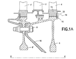
図1Aおよび図1Bは本発明の実施形態を構成する装置を装備した航空ターボ機械の低圧タービンの断片的な長手方向断面図である。 1A and 1B are fragmentary longitudinal cross-sectional views of a low pressure turbine of an aircraft turbomachine equipped with an apparatus constituting an embodiment of the present invention.
当然、本発明は、軸方向に移動することにより装着されるブレードを有するロータディスクを備える任意の他のターボ機械アセンブリ(航空または陸上用途の)に適用する。 Of course, the present invention applies to any other turbomachine assembly (for aviation or land use) comprising a rotor disk with blades mounted by axial movement.
低圧タービンはターボ機械の長手軸X−X上に中心合わせされる。タービンの最終段はノズルを備え、このノズルは、複数の静翼2と、ノズルの後ろに配置され、およびロータディスク6上に軸方向に装着された複数のロータブレード4により形成されるロータホイールとにより形成される。タービンの最後から2番目の段はまた、ノズル(図示せず)と、ロータディスク6’上に装着された複数のロータブレード4’により形成されるロータホイールとを有する。
The low pressure turbine is centered on the longitudinal axis XX of the turbomachine. The last stage of the turbine comprises nozzles, which are formed by a plurality of
タービンの最後および最後から2番目の段のディスク6および6’はボルト結合8により相互に固定され、これらは、環状のトラニオン10によりターボ機械の低圧シャフト(図示せず)に固定されている。トラニオンはまた同じボルト結合8によりディスク6および6’に固定されている。
The last and last
図1Bに示されるとおり、タービンの最終段のディスク6は周辺部に、実質的に軸方向に延びる複数のスロット12を有し、スロットはディスクの外側に通じ(すなわち長手軸X−Xから離れている)、各スロットはタービンのロータブレード4の根元部4a(例えば、クリスマスツリー形の)を軸方向に収容する(例えば、スロット内にはめ込むことにより)ように設計されている。
As shown in FIG. 1B, the
ディスク6はまた、ディスクの下流側の半径方向面14にフランジ16を有し(以下では、ディスクの支持面と称される)、このフランジ16は、ディスクの外側に向かって半径方向に延在し、これにより支持面と協働して外向きに開いている環状の溝18を画定する。
The
各ブレード根元部4aはまた、ロータディスク6の下流側の半径方向面に対応する根元部の下流側の半径方向面に少なくとも1つの尖端部20を備える。この尖端部20はディスクの内側に向かって(すなわち長手軸X−Xに向かって)半径方向に延在し、これにより上記下流側面と協働して内向きに開いている環状のノッチ22を画定する。
Each
本発明の装置は、ロータディスク6の支持面14に接しておよびブレード根元部4aに接して装着されている、保持リング24を含む。保持リング24はディスクの溝18内に収容され、外側をブレード根元部4aのノッチ22内に保持されている。
The apparatus of the present invention includes a
加えて、保持リング24は、端と端をつけて配置された複数の角度セグメント(またはセクタ)24aにより構成され、各リングセグメント24aは同一角距離で円周に沿って延びる。
In addition, the
例として、最終段が98のロータブレードを有するターボ機械の低圧タービンでは、セグメントのそれぞれが25°にわたって延びるように、14のリングセグメント24aを設けることができる。
As an example, in a turbomachine low pressure turbine having 98 rotor blades in the final stage, 14
セグメントをディスク6の溝18内に装着することを可能にするために、各リングセグメント24aは外向きに開いているカットアウト26を含む。図2Aに示されるとおり、これらのカットアウトの大きさは、ブレード根元部4aの尖端部20を通過可能にすると同時に、保持リングがディスクの溝内に装着される寸法とされる。したがって、この位置では、リングセグメントはブレード根元部のノッチ22内に外向きに保持されない。
Each
さらに例として、ロータディスク6は98のロータブレード4を有し、保持リング24は14のセグメント14aにより構成される場合、セグメント当たりのカットアウト26の数は7つであり得る。
As a further example, if the
リングセグメント24aは、ディスクの溝18内に装着されると、ターボ機械の長手軸X−X回りに回転して、ブレード根元部の尖端部20がカットアウト26の位置と一致しなくなる(図2B)。この位置では、次にリングセグメントはブレード根元部のノッチに外向きに保持される。
When the
さらに例として、ロータディスク6は98のロータブレード4を有し、保持リング24は14のセグメント24aで構成され、各セグメントは、7つのカットアウト26を有し、1.8°で保持リングを回転する(いずれか一方の方向において)ことは、図2Aに示されている位置から図2Bに示されている位置に通過するのに役立つ。
As a further example, the
当然、保持リングは、ブレード根元部の尖端部をリングセグメントのカットアウトの位置と再度一致させるのに十分な角度で回転することにより、同じ方法で結合から外れる。 Of course, the retaining ring is disengaged in the same manner by rotating it at an angle sufficient to realign the blade root tip to the position of the ring segment cutout.
本発明の有利な配置では、リングセグメント24aの少なくとも1つは、ブレード根元部4aの2つの隣接する尖端部20間で展開する折曲げタングを含み、これにより、タングが尖端部の間に正しく位置すると、保持リングがロータディスク6の溝18で回ることを防止する(図2B)。
In an advantageous arrangement of the invention, at least one of the
このように、図2Aおよび図2Bの実施形態では、タング28はリングセグメント24aのカットアウト26の1つと同じレベルに置かれ、折曲げられると2つの極限位置を占有するのに適する。2つの極限位置の一方の位置では、タングはリングセグメントの半径方向平面に対して傾斜する平面内に延びて、上記セグメントを回転可能にし(図2A)、他方の位置では、タングはブレード根元部の尖端部20と同一半径方向平面に置かれ、2つの隣接する尖端部20の間で円周方向に延びて、上記セグメントが回転することを防止し、これにより保持リング全体が回転することを防止する(図2B)。
Thus, in the embodiment of FIGS. 2A and 2B, the
リングセグメントのすべてがこのようなタングを取り付ける必要がないことは留意されるべきであり、上記リングの回転を防止するには、セグメントのすべてに対する単一のタングで十分である。 It should be noted that not all of the ring segments need to be fitted with such a tongue, and a single tongue for all of the segments is sufficient to prevent rotation of the ring.
本発明の別の有利な配置では、リングセグメント24aのうちの少なくとも1つが他のセグメントより大きい重量を有する。
In another advantageous arrangement of the invention, at least one of the
このような配置は、低圧タービンにおいて見られる不均衡の補正を容易にする。保持リング24はセグメントに分割されているため、リングセグメントのうちのいくつかに、他のセグメントの重量と異なる個別の重量を与えることにより、ロータディスクの重心がターボ機械の長手軸X−X上に正しく位置することを保証できる。リングセグメントの数が大きくなれば、ディスク全体にわたり正確に重量の釣合いが取れることは留意されるべきである。
Such an arrangement facilitates correction of imbalances found in low pressure turbines. Because the retaining
図1Aに示されるとおり、この配置は、タービンの最終段のディスク6の内端とトラニオン10との間の環状の空間がボルト結合8への直接アクセスを妨害し、その結果、最終タービン段の分解を開始する必要なく、これらのボルト結合に釣合い重りを固定することを不可能にする場合に、特に有利である。
As shown in FIG. 1A, this arrangement allows the annular space between the inner end of the
実際に、ロータディスクは、タービンが組み立てられた後に均衡を確認し、必要な場合は不均衡の補正が次に適用される。不均衡を補正する作業中、1つまたは複数のセグメントが、必要とされる補正に対して適切な変更された重量のセグメントに置き換えられる。変更された重量のセグメントは、他のセグメントより大きい重量のリングセグメントである。 In practice, the rotor disk checks the balance after the turbine is assembled, and if necessary an imbalance correction is then applied. During the work to correct the imbalance, one or more segments are replaced with segments of modified weights appropriate for the required correction. The modified weight segment is a ring segment that is heavier than the other segments.
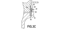
図3Aから図3Cは、本発明による装置の変形実施形態を示す長手方向断面図であり、リングセグメント24aの重量を変更する様々な方法を示している。
3A to 3C are longitudinal cross-sectional views illustrating alternative embodiments of the apparatus according to the present invention, illustrating various ways of changing the weight of the
このように、図3Bの実施形態では、リングセグメント24aは図3Aに示されているセグメントと比較して追加厚さ30を有する。このような余分の厚さに加えて、図3Cのリングセグメント24aは、図3Aのリングセグメントにも図3Bのリングセグメントにも示されていない突出部32を有する。この余分な厚さ30およびこの突出部32はリングセグメントのすべてまたはセグメントの一部のみを超えて円周方向に延在し得る。これらは重量を追加することに相当する。
Thus, in the embodiment of FIG. 3B, the
リングセグメントの重量を変更する他の方法もまた可能である。したがって、カットアウト26の深さ、カットアウト26の間のゾーンの高さおよび/または厚さを変更して、リングセグメントの重量を増加または低減することができる。
Other ways of changing the weight of the ring segment are also possible. Accordingly, the depth of the
リングセグメントを事前に機械加工して、重量の分類(例えばグラムごとに)に適合することにより、必要な不均衡の補正を実行するのに適応されるセグメントの幅広い選択を提供できる。代替として、リングセグメントは要求に応じて機械加工できる。 By pre-machining the ring segments and adapting to weight classification (eg, per gram), a wide selection of segments can be provided that are adapted to perform the necessary imbalance correction. Alternatively, the ring segment can be machined on demand.
軸方向保持ブレードに対する本発明の装置は、多数の利点を提示する。詳細には、単一の主部品(すなわち保持リング)により構成され、これにより、低コストで製造し、およびディスクの支持面に対する装着および/または除去を容易にする。加えて、リングセグメントを使用することにより、これらのセグメントのそれぞれの重量を変更することができ、したがってこの種の技術により観測される不均衡を補正することが容易になる。 The device of the present invention for an axial retaining blade presents a number of advantages. In particular, it consists of a single main part (i.e. a retaining ring), which makes it cheap to manufacture and facilitates mounting and / or removal from the support surface of the disk. In addition, by using ring segments, the weight of each of these segments can be changed, thus making it easier to correct the imbalances observed by this type of technique.
2 静翼
4 ブレード
4a ブレード根元部
6 ロータディスク
8 ボルト結合
10 トラニオン
12 スロット
14 半径方向面
16 フランジ
18 溝
20 尖端部
22 ノッチ
24 保持リング
24a リングセグメント
26 カットアウト
28 タング
30 追加厚さ
32 突出部
2
Claims (5)
ロータディスク(6)が、
ロータディスクの周辺部に、外向きに開いている実質的に軸方向の複数のスロット(12)および、
半径方向の支持面上(14)に、前記支持面と協働して半径方向に外向きに開いている環状の溝(18)を画定する、半径方向の外向きに延在するフランジ(16)を備え、さらに前記装置が、
複数のブレード(4)であって、各ブレードがロータディスクの対応するスロット内に装着される根元部(4a)を備え、各ブレード根元部が、ロータディスクの支持面に相当するロータディスクの半径方向支持面上に、少なくとも1つの尖端部(20)を備え、尖端部が半径方向の内向きに延びてブレード根元部の上記支持面と協働して、半径方向内向きに開いている環状のノッチ(22)を画定する、複数のブレードと、
を備える、装置において、
さらに、ロータディスクのおよびブレード根元部の支持面に接して装着される保持リング(24)を備え、前記保持リングが、ディスクの溝(18)に収容され、ブレード根元部のノッチ(22)内に外向きに保持され、端と端をつけて配置される複数の角度セグメント(24a)により構成され、保持リングの少なくとも1つのセグメントの重量は他のセグメントより大きいことを特徴とする、装置。 A device for axially holding a blade mounted on a rotor disk of a turbomachine, the apparatus comprising a rotor disk (6),
The rotor disk (6)
A plurality of substantially axial slots (12) open outwardly at the periphery of the rotor disk; and
A radially outwardly extending flange (16) defining on the radial support surface (14) an annular groove (18) opening radially outwardly in cooperation with said support surface. And the device further comprises:
A plurality of blades (4), each blade having a root portion (4a) mounted in a corresponding slot of the rotor disk, and each blade root portion corresponding to a support surface of the rotor disk An annular ring having at least one point (20) on the directional support surface, the point extending radially inward and cooperating with the support surface of the blade root to open radially inward A plurality of blades defining a notch (22)
An apparatus comprising:
And a retaining ring (24) mounted in contact with the support surface of the rotor disk and the blade root, wherein the retaining ring is received in the groove (18) of the disk and is located in the notch (22) of the blade root. A device comprising a plurality of angular segments (24a) that are held outwardly and arranged end to end, wherein the weight of at least one segment of the retaining ring is greater than the other segments.
Applications Claiming Priority (2)
| Application Number | Priority Date | Filing Date | Title |
|---|---|---|---|
| FR0756062 | 2007-06-27 | ||
| FR0756062A FR2918106B1 (en) | 2007-06-27 | 2007-06-27 | AXIS RETAINING DEVICE OF AUBES MOUNTED ON A TURBOMACHINE ROTOR DISC. |
Publications (2)
| Publication Number | Publication Date |
|---|---|
| JP2009008085A true JP2009008085A (en) | 2009-01-15 |
| JP5306721B2 JP5306721B2 (en) | 2013-10-02 |
Family
ID=39081577
Family Applications (1)
| Application Number | Title | Priority Date | Filing Date |
|---|---|---|---|
| JP2008166894A Active JP5306721B2 (en) | 2007-06-27 | 2008-06-26 | Device for axially holding a blade mounted on a turbomachine rotor disk |
Country Status (8)
| Country | Link |
|---|---|
| US (1) | US8348620B2 (en) |
| EP (1) | EP2009244B1 (en) |
| JP (1) | JP5306721B2 (en) |
| CN (1) | CN101333942B (en) |
| CA (1) | CA2635635C (en) |
| DE (1) | DE602008002103D1 (en) |
| FR (1) | FR2918106B1 (en) |
| RU (1) | RU2471999C2 (en) |
Cited By (2)
| Publication number | Priority date | Publication date | Assignee | Title |
|---|---|---|---|---|
| JP2017028674A (en) * | 2016-02-12 | 2017-02-02 | Necプラットフォームズ株式会社 | Management device, management method and management program |
| JP7037929B2 (en) | 2016-12-22 | 2022-03-17 | ヌオーヴォ・ピニォーネ・テクノロジー・ソチエタ・レスポンサビリタ・リミタータ | Turbine blade and locking set |
Families Citing this family (18)
| Publication number | Priority date | Publication date | Assignee | Title |
|---|---|---|---|---|
| FR2933442B1 (en) * | 2008-07-04 | 2011-05-27 | Snecma | HOLDING FLANGE FOR RETAINING RING, ASSEMBLY OF TURBOMACHINE ROTOR DISC, RESTRAINT ROD AND HOLDING FLANGE AND TURBOMACHINE COMPRISING SUCH ASSEMBLY |
| DE102010015404B4 (en) * | 2010-04-19 | 2012-02-16 | Mtu Aero Engines Gmbh | Method for repairing a rotor assembly of a turbomachine, ring element for a rotor assembly of a turbomachine and rotor assembly for a turbomachine |
| US8851853B2 (en) * | 2011-05-26 | 2014-10-07 | United Technologies Corporation | Hybrid rotor disk assembly for a gas turbine engine |
| US8834125B2 (en) | 2011-05-26 | 2014-09-16 | United Technologies Corporation | Hybrid rotor disk assembly with a ceramic matrix composite airfoil for a gas turbine engine |
| US8936440B2 (en) | 2011-05-26 | 2015-01-20 | United Technologies Corporation | Hybrid rotor disk assembly with ceramic matrix composites platform for a gas turbine engine |
| DE102011077501A1 (en) * | 2011-06-14 | 2012-12-20 | Rolls-Royce Deutschland Ltd & Co Kg | Rotor device for a jet engine with a disc wheel and a plurality of blades |
| US8979502B2 (en) * | 2011-12-15 | 2015-03-17 | Pratt & Whitney Canada Corp. | Turbine rotor retaining system |
| FR2988128A1 (en) * | 2012-03-19 | 2013-09-20 | Alstom Technology Ltd | TURBINE ROTOR FOR A THERMOELECTRIC POWER PLANT |
| EP2964894B1 (en) | 2013-03-05 | 2019-04-10 | Rolls-Royce North American Technologies, Inc. | Turbine segmented cover plate retention method |
| GB2506712B (en) * | 2013-05-14 | 2018-05-02 | Rolls Royce Plc | Balancing method |
| US9624775B2 (en) * | 2014-05-30 | 2017-04-18 | Rolls-Royce Plc | Developments in or relating to rotor balancing |
| EP3009608B1 (en) | 2014-10-02 | 2019-10-30 | United Technologies Corporation | Vane assembly with trapped segmented vane structures |
| US10724384B2 (en) | 2016-09-01 | 2020-07-28 | Raytheon Technologies Corporation | Intermittent tab configuration for retaining ring retention |
| US10415401B2 (en) | 2016-09-08 | 2019-09-17 | United Technologies Corporation | Airfoil retention assembly for a gas turbine engine |
| CN108808905B (en) * | 2017-05-04 | 2020-07-28 | 东元电机股份有限公司 | Method for producing a segmented rotor structure |
| US10458244B2 (en) | 2017-10-18 | 2019-10-29 | United Technologies Corporation | Tuned retention ring for rotor disk |
| FR3082232B1 (en) * | 2018-06-12 | 2020-08-28 | Safran Aircraft Engines | HOLDING SYSTEM FOR DISMANTLING A BLADE WHEEL |
| IT201900014739A1 (en) * | 2019-08-13 | 2021-02-13 | Ge Avio Srl | Elements for retaining blades for turbomachinery. |
Citations (3)
| Publication number | Priority date | Publication date | Assignee | Title |
|---|---|---|---|---|
| FR2524933A1 (en) * | 1982-04-13 | 1983-10-14 | Snecma | Turbine rotor blade root retainer - has grooved root packing engaging with circumferential grooves and other parts |
| US4730983A (en) * | 1986-09-03 | 1988-03-15 | Societe Nationale D'etude Et De Construction De Moteurs D'aviation "Snecma" | System for attaching a rotor blade to a rotor disk |
| JPH06280502A (en) * | 1993-02-03 | 1994-10-04 | Rolls Royce Plc | Balance rotor |
Family Cites Families (24)
| Publication number | Priority date | Publication date | Assignee | Title |
|---|---|---|---|---|
| US2751189A (en) * | 1950-09-08 | 1956-06-19 | United Aircraft Corp | Blade fastening means |
| US3181835A (en) * | 1964-01-07 | 1965-05-04 | Carroll C Davis | Blade vibration damping device |
| US3853425A (en) * | 1973-09-07 | 1974-12-10 | Westinghouse Electric Corp | Turbine rotor blade cooling and sealing system |
| US3888601A (en) * | 1974-05-23 | 1975-06-10 | Gen Electric | Turbomachine with balancing means |
| GB1479332A (en) * | 1974-11-06 | 1977-07-13 | Rolls Royce | Means for retaining blades to a disc or like structure |
| US4648799A (en) * | 1981-09-22 | 1987-03-10 | Westinghouse Electric Corp. | Cooled combustion turbine blade with retrofit blade seal |
| US4645425A (en) * | 1984-12-19 | 1987-02-24 | United Technologies Corporation | Turbine or compressor blade mounting |
| FR2663997B1 (en) * | 1990-06-27 | 1993-12-24 | Snecma | DEVICE FOR FIXING A REVOLUTION CROWN ON A TURBOMACHINE DISC. |
| US5244348A (en) * | 1991-12-18 | 1993-09-14 | Brunswick Corporation | Propeller drive sleeve |
| US5211407A (en) * | 1992-04-30 | 1993-05-18 | General Electric Company | Compressor rotor cross shank leak seal for axial dovetails |
| US5256035A (en) * | 1992-06-01 | 1993-10-26 | United Technologies Corporation | Rotor blade retention and sealing construction |
| FR2728299B1 (en) * | 1994-12-14 | 1997-01-24 | Snecma | DEVICE FOR AXIAL FIXING OF TURBO-SPINDLE ROTOR BLADES |
| US5518369A (en) * | 1994-12-15 | 1996-05-21 | Pratt & Whitney Canada Inc. | Gas turbine blade retention |
| FR2812906B1 (en) * | 2000-08-10 | 2002-09-20 | Snecma Moteurs | AXIAL RETAINER RING OF A FLANGE ON A DISC |
| US6951448B2 (en) * | 2002-04-16 | 2005-10-04 | United Technologies Corporation | Axial retention system and components thereof for a bladed rotor |
| RU2238412C1 (en) * | 2003-04-28 | 2004-10-20 | Открытое акционерное общество "Научно-производственное объединение "Сатурн" | Turbine wheel |
| FR2857691B1 (en) * | 2003-07-17 | 2006-02-03 | Snecma Moteurs | RETENTION OF ROTOR FLASK |
| FR2861128B1 (en) * | 2003-10-16 | 2007-06-08 | Snecma Moteurs | DEVICE FOR ATTACHING A MOBILE DARK TO A TURBINE ROTOR DISK IN A TURBOMACHINE |
| EP1619354B1 (en) * | 2004-07-22 | 2008-04-09 | Siemens Aktiengesellschaft | Device for fixing a blade on a rotor disc of a turbomachine, turbomachine and method to assemble and disassemble a blade on a rotor disc of a turbomachine. |
| GB0503676D0 (en) * | 2005-02-23 | 2005-03-30 | Rolls Royce Plc | A lock plate arrangement |
| DE102005035901A1 (en) * | 2005-07-30 | 2007-02-01 | Mtu Aero Engines Gmbh | Rotor blades` position securing unit for gas turbine, has plate-like base body having recess formed between its two end sections, where recess defines middle section of body and sections have contact surfaces running parallel to each other |
| US7500832B2 (en) * | 2006-07-06 | 2009-03-10 | Siemens Energy, Inc. | Turbine blade self locking seal plate system |
| DE602006006452D1 (en) * | 2006-09-25 | 2009-06-04 | Siemens Ag | Turbine rotor with closure plates and corresponding assembly process |
| US8128371B2 (en) * | 2007-02-15 | 2012-03-06 | General Electric Company | Method and apparatus to facilitate increasing turbine rotor efficiency |
-
2007
- 2007-06-27 FR FR0756062A patent/FR2918106B1/en not_active Expired - Fee Related
-
2008
- 2008-06-24 EP EP08158843A patent/EP2009244B1/en active Active
- 2008-06-24 DE DE602008002103T patent/DE602008002103D1/en active Active
- 2008-06-25 US US12/145,882 patent/US8348620B2/en active Active
- 2008-06-26 RU RU2008126092/06A patent/RU2471999C2/en active
- 2008-06-26 JP JP2008166894A patent/JP5306721B2/en active Active
- 2008-06-26 CA CA2635635A patent/CA2635635C/en active Active
- 2008-06-27 CN CN200810127534.5A patent/CN101333942B/en active Active
Patent Citations (3)
| Publication number | Priority date | Publication date | Assignee | Title |
|---|---|---|---|---|
| FR2524933A1 (en) * | 1982-04-13 | 1983-10-14 | Snecma | Turbine rotor blade root retainer - has grooved root packing engaging with circumferential grooves and other parts |
| US4730983A (en) * | 1986-09-03 | 1988-03-15 | Societe Nationale D'etude Et De Construction De Moteurs D'aviation "Snecma" | System for attaching a rotor blade to a rotor disk |
| JPH06280502A (en) * | 1993-02-03 | 1994-10-04 | Rolls Royce Plc | Balance rotor |
Cited By (2)
| Publication number | Priority date | Publication date | Assignee | Title |
|---|---|---|---|---|
| JP2017028674A (en) * | 2016-02-12 | 2017-02-02 | Necプラットフォームズ株式会社 | Management device, management method and management program |
| JP7037929B2 (en) | 2016-12-22 | 2022-03-17 | ヌオーヴォ・ピニォーネ・テクノロジー・ソチエタ・レスポンサビリタ・リミタータ | Turbine blade and locking set |
Also Published As
| Publication number | Publication date |
|---|---|
| CN101333942A (en) | 2008-12-31 |
| RU2471999C2 (en) | 2013-01-10 |
| FR2918106A1 (en) | 2009-01-02 |
| CA2635635C (en) | 2013-01-22 |
| RU2008126092A (en) | 2010-01-10 |
| EP2009244A1 (en) | 2008-12-31 |
| FR2918106B1 (en) | 2011-05-06 |
| US8348620B2 (en) | 2013-01-08 |
| US20090004018A1 (en) | 2009-01-01 |
| EP2009244B1 (en) | 2010-08-11 |
| JP5306721B2 (en) | 2013-10-02 |
| CA2635635A1 (en) | 2008-12-27 |
| CN101333942B (en) | 2013-07-24 |
| DE602008002103D1 (en) | 2010-09-23 |
Similar Documents
| Publication | Publication Date | Title |
|---|---|---|
| JP5306721B2 (en) | Device for axially holding a blade mounted on a turbomachine rotor disk | |
| JP4809798B2 (en) | Ring sector fixing device to turbine cowling of turbine engine | |
| JP4716772B2 (en) | A device for balancing rotating parts, especially turbojet rotors | |
| RU2532868C2 (en) | Turbine guide vanes for gas turbine engine, sector of guide vanes, continuous circular bracket, low pressure turbine of gas turbine engine and gas turbine engine | |
| US8727719B2 (en) | Annular flange for fastening a rotor or stator element in a turbomachine | |
| JP6336437B2 (en) | Turbine stage for turbine engine | |
| RU2459120C2 (en) | Gas-turbine engine fan | |
| US9605552B2 (en) | Non-integral segmented angel-wing seal | |
| JP5647975B2 (en) | An annular flange for mounting a rotor or stator element | |
| JP5726747B2 (en) | Turbine wheel having an axial holding device for locking the blade to the disk | |
| US9011098B2 (en) | Propeller for an aircraft turbine engine comprising a vane retaining ring mounted about the hub | |
| RU2008134590A (en) | FAN FOR AIRCRAFT TURBO MACHINE CONTAINING A BALANCING FLANGE CLOSED BY INLET CONE | |
| US8661641B2 (en) | Rotor blade assembly tool for gas turbine engine | |
| JP2005299650A (en) | Device for matching and assembling annular flanges in turbo machine, in particular | |
| JP5427398B2 (en) | Turbomachined sectorized nozzle | |
| JP2005248953A (en) | Turbo machine with small roller bearing | |
| JP2009008086A (en) | Device for cooling slot of turbomachine rotor disk | |
| US10012390B2 (en) | Combustion chamber of a gas turbine with bolted combustion chamber head | |
| JP2009008084A (en) | Device for cooling slot of rotor disk in turbomachine with two air supply | |
| US20110085914A1 (en) | Annulus filler element for a rotor of a turbomachine | |
| JP2009097510A (en) | Improvement of pitch control ring for stator blade of turbomachine | |
| JP2010230007A (en) | Turbomachine rotor assembly and method of assembling the same | |
| US8702374B2 (en) | Gas turbine engine | |
| JP2015500424A (en) | Releasable device for axially constraining a sealing ring in contact with an aircraft turbomachine module rotor wheel | |
| US20160177835A1 (en) | Gas turbine engine with angularly offset turbine vanes |
Legal Events
| Date | Code | Title | Description |
|---|---|---|---|
| A621 | Written request for application examination |
Free format text: JAPANESE INTERMEDIATE CODE: A621 Effective date: 20110513 |
|
| A131 | Notification of reasons for refusal |
Free format text: JAPANESE INTERMEDIATE CODE: A131 Effective date: 20120828 |
|
| A521 | Request for written amendment filed |
Free format text: JAPANESE INTERMEDIATE CODE: A523 Effective date: 20121127 |
|
| RD02 | Notification of acceptance of power of attorney |
Free format text: JAPANESE INTERMEDIATE CODE: A7422 Effective date: 20121127 |
|
| RD04 | Notification of resignation of power of attorney |
Free format text: JAPANESE INTERMEDIATE CODE: A7424 Effective date: 20130128 |
|
| TRDD | Decision of grant or rejection written | ||
| A01 | Written decision to grant a patent or to grant a registration (utility model) |
Free format text: JAPANESE INTERMEDIATE CODE: A01 Effective date: 20130528 |
|
| A61 | First payment of annual fees (during grant procedure) |
Free format text: JAPANESE INTERMEDIATE CODE: A61 Effective date: 20130626 |
|
| R150 | Certificate of patent or registration of utility model |
Free format text: JAPANESE INTERMEDIATE CODE: R150 Ref document number: 5306721 Country of ref document: JP Free format text: JAPANESE INTERMEDIATE CODE: R150 |
|
| R250 | Receipt of annual fees |
Free format text: JAPANESE INTERMEDIATE CODE: R250 |
|
| R250 | Receipt of annual fees |
Free format text: JAPANESE INTERMEDIATE CODE: R250 |
|
| R250 | Receipt of annual fees |
Free format text: JAPANESE INTERMEDIATE CODE: R250 |
|
| R250 | Receipt of annual fees |
Free format text: JAPANESE INTERMEDIATE CODE: R250 |
|
| R250 | Receipt of annual fees |
Free format text: JAPANESE INTERMEDIATE CODE: R250 |
|
| R250 | Receipt of annual fees |
Free format text: JAPANESE INTERMEDIATE CODE: R250 |
|
| R250 | Receipt of annual fees |
Free format text: JAPANESE INTERMEDIATE CODE: R250 |
|
| R250 | Receipt of annual fees |
Free format text: JAPANESE INTERMEDIATE CODE: R250 |