JP2008545588A - Apparatus and method for evacuating a storage bag - Google Patents
Apparatus and method for evacuating a storage bag Download PDFInfo
- Publication number
- JP2008545588A JP2008545588A JP2008513605A JP2008513605A JP2008545588A JP 2008545588 A JP2008545588 A JP 2008545588A JP 2008513605 A JP2008513605 A JP 2008513605A JP 2008513605 A JP2008513605 A JP 2008513605A JP 2008545588 A JP2008545588 A JP 2008545588A
- Authority
- JP
- Japan
- Prior art keywords
- storage bag
- valve element
- housing
- inflow opening
- way valve
- Prior art date
- Legal status (The legal status is an assumption and is not a legal conclusion. Google has not performed a legal analysis and makes no representation as to the accuracy of the status listed.)
- Pending
Links
- 238000000034 method Methods 0.000 title claims description 14
- 230000002093 peripheral effect Effects 0.000 claims description 12
- 238000007789 sealing Methods 0.000 claims description 10
- 238000004891 communication Methods 0.000 claims description 8
- 239000013536 elastomeric material Substances 0.000 claims description 2
- 239000003570 air Substances 0.000 description 25
- 239000000463 material Substances 0.000 description 14
- 239000000853 adhesive Substances 0.000 description 6
- 230000001070 adhesive effect Effects 0.000 description 6
- 229920001169 thermoplastic Polymers 0.000 description 6
- 239000004416 thermosoftening plastic Substances 0.000 description 6
- 229920002457 flexible plastic Polymers 0.000 description 4
- 239000012530 fluid Substances 0.000 description 4
- 230000009471 action Effects 0.000 description 3
- 229920001971 elastomer Polymers 0.000 description 3
- 239000000806 elastomer Substances 0.000 description 3
- 239000012815 thermoplastic material Substances 0.000 description 3
- 239000012080 ambient air Substances 0.000 description 2
- 230000008901 benefit Effects 0.000 description 2
- 239000006260 foam Substances 0.000 description 2
- 230000005484 gravity Effects 0.000 description 2
- 229920005669 high impact polystyrene Polymers 0.000 description 2
- 239000004797 high-impact polystyrene Substances 0.000 description 2
- 238000012986 modification Methods 0.000 description 2
- 230000004048 modification Effects 0.000 description 2
- 230000002265 prevention Effects 0.000 description 2
- 238000004804 winding Methods 0.000 description 2
- 239000004677 Nylon Substances 0.000 description 1
- 230000008878 coupling Effects 0.000 description 1
- 238000010168 coupling process Methods 0.000 description 1
- 238000005859 coupling reaction Methods 0.000 description 1
- 239000006261 foam material Substances 0.000 description 1
- -1 for example Substances 0.000 description 1
- 235000011389 fruit/vegetable juice Nutrition 0.000 description 1
- 230000006870 function Effects 0.000 description 1
- 239000004519 grease Substances 0.000 description 1
- 229920001903 high density polyethylene Polymers 0.000 description 1
- 239000004700 high-density polyethylene Substances 0.000 description 1
- 230000001788 irregular Effects 0.000 description 1
- 239000007788 liquid Substances 0.000 description 1
- 239000000314 lubricant Substances 0.000 description 1
- 230000007246 mechanism Effects 0.000 description 1
- 229920001778 nylon Polymers 0.000 description 1
- 239000003921 oil Substances 0.000 description 1
- 239000004417 polycarbonate Substances 0.000 description 1
- 229920000515 polycarbonate Polymers 0.000 description 1
- 239000011345 viscous material Substances 0.000 description 1
Images


Classifications
-
- B—PERFORMING OPERATIONS; TRANSPORTING
- B65—CONVEYING; PACKING; STORING; HANDLING THIN OR FILAMENTARY MATERIAL
- B65D—CONTAINERS FOR STORAGE OR TRANSPORT OF ARTICLES OR MATERIALS, e.g. BAGS, BARRELS, BOTTLES, BOXES, CANS, CARTONS, CRATES, DRUMS, JARS, TANKS, HOPPERS, FORWARDING CONTAINERS; ACCESSORIES, CLOSURES, OR FITTINGS THEREFOR; PACKAGING ELEMENTS; PACKAGES
- B65D33/00—Details of, or accessories for, sacks or bags
- B65D33/01—Ventilation or drainage of bags
-
- B—PERFORMING OPERATIONS; TRANSPORTING
- B65—CONVEYING; PACKING; STORING; HANDLING THIN OR FILAMENTARY MATERIAL
- B65D—CONTAINERS FOR STORAGE OR TRANSPORT OF ARTICLES OR MATERIALS, e.g. BAGS, BARRELS, BOTTLES, BOXES, CANS, CARTONS, CRATES, DRUMS, JARS, TANKS, HOPPERS, FORWARDING CONTAINERS; ACCESSORIES, CLOSURES, OR FITTINGS THEREFOR; PACKAGING ELEMENTS; PACKAGES
- B65D81/00—Containers, packaging elements, or packages, for contents presenting particular transport or storage problems, or adapted to be used for non-packaging purposes after removal of contents
- B65D81/18—Containers, packaging elements, or packages, for contents presenting particular transport or storage problems, or adapted to be used for non-packaging purposes after removal of contents providing specific environment for contents, e.g. temperature above or below ambient
- B65D81/20—Containers, packaging elements, or packages, for contents presenting particular transport or storage problems, or adapted to be used for non-packaging purposes after removal of contents providing specific environment for contents, e.g. temperature above or below ambient under vacuum or superatmospheric pressure, or in a special atmosphere, e.g. of inert gas
- B65D81/2007—Containers, packaging elements, or packages, for contents presenting particular transport or storage problems, or adapted to be used for non-packaging purposes after removal of contents providing specific environment for contents, e.g. temperature above or below ambient under vacuum or superatmospheric pressure, or in a special atmosphere, e.g. of inert gas under vacuum
- B65D81/2038—Containers, packaging elements, or packages, for contents presenting particular transport or storage problems, or adapted to be used for non-packaging purposes after removal of contents providing specific environment for contents, e.g. temperature above or below ambient under vacuum or superatmospheric pressure, or in a special atmosphere, e.g. of inert gas under vacuum with means for establishing or improving vacuum
-
- B—PERFORMING OPERATIONS; TRANSPORTING
- B65—CONVEYING; PACKING; STORING; HANDLING THIN OR FILAMENTARY MATERIAL
- B65B—MACHINES, APPARATUS OR DEVICES FOR, OR METHODS OF, PACKAGING ARTICLES OR MATERIALS; UNPACKING
- B65B31/00—Packaging articles or materials under special atmospheric or gaseous conditions; Adding propellants to aerosol containers
- B65B31/04—Evacuating, pressurising or gasifying filled containers or wrappers by means of nozzles through which air or other gas, e.g. an inert gas, is withdrawn or supplied
- B65B31/046—Evacuating, pressurising or gasifying filled containers or wrappers by means of nozzles through which air or other gas, e.g. an inert gas, is withdrawn or supplied the nozzles co-operating, or being combined, with a device for opening or closing the container or wrapper
- B65B31/047—Evacuating, pressurising or gasifying filled containers or wrappers by means of nozzles through which air or other gas, e.g. an inert gas, is withdrawn or supplied the nozzles co-operating, or being combined, with a device for opening or closing the container or wrapper the nozzles co-operating with a check valve in the opening of the container or wrapper
-
- B—PERFORMING OPERATIONS; TRANSPORTING
- B65—CONVEYING; PACKING; STORING; HANDLING THIN OR FILAMENTARY MATERIAL
- B65D—CONTAINERS FOR STORAGE OR TRANSPORT OF ARTICLES OR MATERIALS, e.g. BAGS, BARRELS, BOTTLES, BOXES, CANS, CARTONS, CRATES, DRUMS, JARS, TANKS, HOPPERS, FORWARDING CONTAINERS; ACCESSORIES, CLOSURES, OR FITTINGS THEREFOR; PACKAGING ELEMENTS; PACKAGES
- B65D31/00—Bags or like containers made of paper and having structural provision for thickness of contents
- B65D31/14—Valve bags, i.e. with valves for filling
Abstract
一態様において、間隙を画定する平行な第1および第2フラットパネルを有する、一方向バルブ要素を有する保管バッグを真空化するためのブラケットが設けられる。バッグのバルブ要素が第1パネルに配置された孔と整合するように、バッグが間隙に載置される。バッグを真空化するため、真空装置のノズルが孔に挿入され、バルブ要素の周囲のバッグ側壁に押圧される。真空装置が作動すると、バッグの側壁がノズルの周縁部に引き寄せられ、バルブ要素を通して空気が吸引される。別の実施例では、ノズルが孔の周囲で第1パネルに押圧される。別の態様では、ブラケットが手持ち式真空装置の一部として含まれる。In one aspect, a bracket is provided for evacuating a storage bag having a one-way valve element having parallel first and second flat panels defining a gap. The bag is placed in the gap so that the valve element of the bag is aligned with the hole located in the first panel. In order to evacuate the bag, the nozzle of the vacuum device is inserted into the hole and pressed against the bag side wall around the valve element. When the vacuum device is activated, the side wall of the bag is drawn to the periphery of the nozzle and air is drawn through the valve element. In another embodiment, the nozzle is pressed against the first panel around the hole. In another aspect, a bracket is included as part of the handheld vacuum device.
Description
本発明は、一般的に保管容器、より詳しくは密封および真空化されるように設計された可撓性の熱可塑性保管バッグに関連する。本発明は、特に食品保管の分野に応用が可能である。 The present invention relates generally to storage containers, and more particularly to flexible thermoplastic storage bags designed to be sealed and evacuated. The present invention is particularly applicable to the field of food storage.
保管バッグは通常、食品の保管など多様な目的に使用される。このような保管バッグは一般的に、食品が挿入される内部空間を設けるような構造を持つ可撓性かつ熱可塑性の巻取材料で製造される。挿入された食品を保存するため、内部空間を利用可能にするための開口部を密封状態で閉鎖するための、インタロック締結ストリップなどの独特な閉鎖機構も含む。 Storage bags are usually used for various purposes, such as food storage. Such storage bags are generally made of a flexible and thermoplastic winding material that is structured to provide an interior space into which food is inserted. It also includes a unique closure mechanism, such as an interlock fastening strip, for sealingly closing the opening to make the interior space available to store the inserted food.
上述した保管バッグに関して発生する問題の一つは、開口部を密封状態で閉鎖した後に内部空間に内在空気が封入されたままとなることである。封入された空気は、食品の腐敗または乾燥を引き起こすことがある。封入された空気を除去するため、内部空間と連通する一方向バルブ要素または他の真空装置を設けることは周知である。一方向バルブ要素は、周囲空間から内部空間への空気の流入を防止しながら、封入空気の排出を可能にする。バルブ要素から空気を排出する周知の方法の一つは、水平面に保管バッグを置き、バルブ要素を囲繞するように真空装置のノズルをバッグに載置することである。作動すると、真空装置はバルブ要素を通して内部空間から空気を吸引する。 One of the problems that occur with the storage bag described above is that the internal air remains sealed in the internal space after the opening is closed in a sealed state. Enclosed air can cause food to rot or dry. It is well known to provide a one-way valve element or other vacuum device in communication with the interior space to remove encapsulated air. The one-way valve element allows for the discharge of enclosed air while preventing the inflow of air from the surrounding space into the interior space. One known method of evacuating air from the valve element is to place a storage bag on a horizontal surface and place a vacuum device nozzle on the bag to surround the valve element. When activated, the vacuum device draws air from the interior space through the valve element.
上記の方法で保管バッグを真空化する時に、側壁の可撓性材料にはある問題が見られる。発生する問題の一つは、真空装置ノズルからの印加圧力を受けて可撓性側壁が歪んで変形し、ノズルと保管バッグとの間の真空密着シールの形成を困難にして真空化を妨げることである。また一部には側壁材料の可撓性のため、真空化の際の支持のため保管バッグはテーブル面などの表面に水平に置かれることが多い。水平に置かれると、バッグの中身はバルブ要素の方へ移動して、バルブ要素を通して真空装置へと吸引される。 When vacuuming the storage bag in the manner described above, certain problems are seen with the side wall flexible material. One of the problems that occur is that the flexible side wall is distorted and deformed by the pressure applied from the vacuum device nozzle, making it difficult to form a vacuum tight seal between the nozzle and the storage bag, preventing vacuuming. It is. Also, due to the flexibility of the side wall material in part, the storage bag is often placed horizontally on a surface such as a table surface for support during vacuuming. When placed horizontally, the contents of the bag move toward the valve element and are drawn through the valve element into the vacuum device.
本発明は、一方向バルブ要素を利用する保管バッグの真空化を簡単にし、改良する装置および方法を提供する。一実施例において本発明は、真空化の際に可撓性保管バッグを支持するのに適応した比較的剛性のブラケットを提供する。ブラケットは、可撓性保管バッグが挿入される間隙を間に備える二つのほぼ平行で離間したパネルを有する。一方向バルブ要素を利用可能にするため、パネルの一方には孔が配置される。バッグを真空化するため、真空装置のノズルが孔へ挿入されて、バルブ要素の周囲のバッグ側壁の付近に押圧される。孔はノズルとバルブ要素との整合を助けるため、シールの改良が実現する。そのうえ、ブラケットの第1および第2パネルは、真空化の際に保管バッグがノズルへ吸引されるのを防止するのに役立つクランプ作用を提供する。別の長所は、中身が重力によってバルブ要素から離間してバッグの底部へ落下するように、ブラケットにより保管バッグが垂直に保持されることである。 The present invention provides an apparatus and method that simplifies and improves the evacuation of storage bags that utilize one-way valve elements. In one embodiment, the present invention provides a relatively rigid bracket adapted to support a flexible storage bag during vacuuming. The bracket has two generally parallel spaced panels with a gap between which the flexible storage bag is inserted. To make the one-way valve element available, a hole is placed in one of the panels. In order to evacuate the bag, the nozzle of the vacuum device is inserted into the hole and pressed near the bag side wall around the valve element. The hole helps to align the nozzle and valve element, thus providing an improved seal. Moreover, the first and second panels of the bracket provide a clamping action that helps to prevent the storage bag from being sucked into the nozzle during vacuuming. Another advantage is that the storage bag is held vertically by the bracket so that the contents fall away from the valve element by gravity and onto the bottom of the bag.
別の実施例では、真空装置のノズルが孔の周囲で第1パネルの付近に押圧される。ノズルは可撓性保管バッグでなく比較的剛性のブラケットと接触するため、シールの改良が実現される。加えて、ブラケットおよび孔によりノズルとバルブ要素との正確な整合も保証される。 In another embodiment, the nozzle of the vacuum device is pressed near the first panel around the hole. An improved seal is realized because the nozzle contacts a relatively rigid bracket rather than a flexible storage bag. In addition, the bracket and the hole ensure an exact alignment of the nozzle and the valve element.
別の実施例では、本発明は、一方向バルブ要素を有する保管バッグを真空化するための装置を提供する。真空装置は、電動式気流発生ユニットを包囲するハウジングも含む。気流発生ユニットは、保管バッグに装着された一方向バルブ要素の周囲に載置されるのに適応したハウジングに配置された流入開口部と連通する。真空化の際に真空装置と保管バッグとの間に確立されなければならない気密シールを改良するため、真空装置は流入開口部の周縁部に装着されたガスケットを含む。別の面では、真空装置は、間に間隙を備える平行で離間した第1および第2パネルを有するブラケットを含む。可撓性保管バッグは間隙へ挿入され、一方向バルブ要素は上述した方法で流入開口部と整合する。真空装置の長所の一つは、ガスケットおよび/またはブラケットにより得られる改良型シールである。 In another embodiment, the present invention provides an apparatus for evacuating a storage bag having a one-way valve element. The vacuum apparatus also includes a housing that encloses the electric airflow generation unit. The airflow generating unit communicates with an inflow opening disposed in a housing adapted to be mounted around a one-way valve element mounted on a storage bag. In order to improve the hermetic seal that must be established between the vacuum device and the storage bag during evacuation, the vacuum device includes a gasket attached to the periphery of the inlet opening. In another aspect, the vacuum apparatus includes a bracket having parallel spaced apart first and second panels with a gap therebetween. The flexible storage bag is inserted into the gap and the one-way valve element is aligned with the inflow opening in the manner described above. One of the advantages of the vacuum device is an improved seal obtained with a gasket and / or bracket.
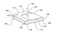
同様の参照符号が同様の要素を指す図面を参照すると、可撓性保管バッグ102に載置される、本発明の教示により設計された支持ブラケット100が図1に図示されている。進歩性を持つ支持ブラケット100との使用を目的とするタイプの保管バッグ102は、一般的に、内部空間120を設けるように第1および第2側縁部114,116と閉鎖された底縁部118とに沿って結合される可撓性かつ熱可塑性の巻取材料による第1および第2側壁110,112から製造される。内部空間120を利用可能にするため、第1および第2側壁110,112の上縁部を接続されないままにしておくことにより開口部122が設けられている。所望の際に開口部122を一時的に密封するため、保管バッグ102はインタロック締結ストリップ124を含む。
Referring to the drawings wherein like reference numerals refer to like elements, a
理解できるように、いったん開口部122が密封状態で閉鎖されると、保管バッグ102の内部空間120には内在空気が封入されたままとなることがある。内在空気は、内部空間に保管された食品を腐敗させ、バッグをかさばらせることになり、望ましくない。封入空気を除去するため、内部空間120と連通する、第1可撓性側壁110に装着された一方向バルブ要素128を保管バッグ102が備える。例えば、真空装置のノズル130を一方向バルブ要素128の周囲に載置し、装置を作動させバルブ要素を通して空気を吸引することにより、内部空間から空気が排出される。
As can be appreciated, once the opening 122 is closed in a sealed state, the
保管バッグ102からの空気の排出を容易にするため、バッグは進歩性を持つ支持ブラケット100に挿入される。図1,3,4を参照すると、ブラケット100は、第1パネル150とほぼ同一の第2パネル152とを含む。第1および第2パネル150,152は平坦な平面構造であり、適当な形状を有すればよいが、図示された実施例では、パネルは矩形であり、各々が第1長縁部160,162および平行な第2長縁部164,166を備えるとともに、各々が第1短縁部170,172および平行な第2短縁部174,176とを備える。パネル150,152は、可撓性保管バッグ102を収容するための間隙154を間に設けるように、相互に平行に離間して配置される。パネル150,152の内面および外面は凹凸のない仕上げである。離間したパネル150,152を一緒に接続するため、対応する第1長縁部160,162に沿ってU字形部分156が延在している。ブラケット100は、例えば比較的剛性の熱可塑性物質を含む適当な材料で製造される。
In order to facilitate the discharge of air from the
第1および第2パネル150,152の間に保管バッグ102が挿入された時に一方向バルブ要素128を利用可能にするため、第1パネル150には孔180が配置されている。孔180は図示された円形を含む適当な形状を有する。図1と2を参照すると、保管バッグ102の開口上縁部122からバルブ要素128が離間している距離に対応する第1長縁部160,162からの所定距離に、孔180が配置されている。さらに、孔180は、バルブ要素128がバッグ100の第1側縁部114から離間しているのと同じ距離だけ第1短側縁部170,172から離間している。したがって、開口上縁部122がU字形部分156と当接して第1側縁部112が第1短縁部170,172と一致するように、保管バッグ100が第1および第2パネル150,152の間に挿入されると、バルブ要素128が孔162と整合するのである。
A
保管バッグ102を真空化するには、ノズル130が第1パネル150の孔180に挿入され、保管バッグ102の第1側壁110の付近に押圧される。バルブ要素128が孔180と正確に整合されると、ノズル130はバルブ要素の周囲に延在する。ノズル130を円形の孔130に嵌着させてバルブ要素128の周囲に延在させるため、図示された実施例では、ノズル130も円形であって孔よりも短い直径を有する。この実施例では、ノズル130はバルブ要素よりも長い直径を有する。他の実施例では、孔に挿入されると、ノズルはバルブ要素と接触して、バルブ要素とほぼ同じサイズであってもよい。ノズル130に装着された真空装置130が作動すると、発生する吸引力が、ノズルの周縁部の付近で孔180から露出する第1側壁110の一部分を吸引することにより、ノズルとバルブ要素128との間に気密境界面を設ける。保管バッグ102の残部はブラケット100内に拘束されるため、さらに吸引すると、一方向バルブ要素128を通して内部空間120から内在空気を吸引する。
In order to evacuate the
ノズル130とバッグ側壁110との間の密封境界面をさらに改良するため、周縁部に装着された環状ガスケット132をノズルが含むことが可能である。そのうえ、孔180は、ノズル130をバルブ要素128と整合させて保管バッグ100の真空化を容易にする。さらに、保管バッグ102は第1および第2パネル150,152の間に保持されて、孔180を介して真空装置に露出しているに過ぎないため、ブラケット100は真空化の際にバッグがノズルへ吸引されるのを抑制する。図1から明らかなように、真空化の際にブラケット100は、上部とバルブ要素128とが横に折り曲げられた状態でバッグ102が垂直に保持されることを可能にする。こうして、バッグ100の中身は重力により底縁部118へ落下して、真空化の際にバルブ要素128およびノズルへ吸引される可能性が低い。
To further improve the sealing interface between the
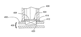
図5に図示されているのは、上記のタイプのブラケット200を使用して保管バッグ202を真空化する別の方法である。上述したように孔へ挿入される代わりに、真空装置に接続されたノズル230は、孔280の周囲で第1パネル250に押圧される。円形の孔280の周囲に嵌着するため、図示された実施例では、ノズル230も円形で孔よりも長い直径を有するべきである。ブラケット200は剛性で第1パネル250の外面は凹凸がないため、ノズル230はバルブ要素228の上で孔280の周りに気密状態で接触する。ノズルとブラケット200との間の密封境界面をさらに改良するため、ノズル230は、周縁部に装着された環状ガスケット232も含むことが可能である。真空装置が作動すると、図5から理解できるように、ノズル230での吸引により、第1パネル250の内面の付近の第1側壁210を引き寄せることにより、周囲の空気がノズルへ流入するのを阻止する。さらに吸引すると、バルブ要素228を通して内部空間222から内在空気が吸い出されて保管バッグ202を真空化する。こうして、ブラケット200は真空化の際に可撓性保管バッグ202を支持する役割を果たし、ノズル230が押圧される剛性の支持面となる。
Illustrated in FIG. 5 is another method of evacuating the
図5には、ともにその全体が参考として取り入れられている米国特許出願第11/039,735号および米国特許出願番号第11/166,574号に記載されたような流体分離器240を有する保管バッグ202に使用されるブラケット200が図示されている。これらの出願に記載された保管バッグ202は、真空供給源の影響を受けて膨張してバルブ要素228を第2側壁212から離間させる室242を設ける、第1側壁210に形成または装着された流体分離器240を有する。分離器240により設けられる室242は、排気に混入した流体およびジュースを分離するように機能する。図示された実施例では、分離器240が膨張形状へ膨張するのを孔280が可能にし、補助するため、孔はサイズおよび形状において分離器と対応する。ゆえに、分離器240は孔280を通って膨張し、孔により輪郭が形成される。
FIG. 5 shows storage with a
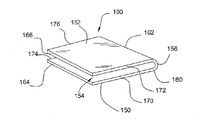
図6に図示されているのは、一方向バルブ要素328を有する保管バッグ302を収容する上記設計のブラケット300である。バルブ要素328と、ブラケット300の第1パネル350に配置された孔380との整合を容易にするため、バルブ要素が保管バッグ302の縁部312から離間している距離は、孔がU字形部分356から離間している距離と寸法的に対応する。そのうえ、保管バッグ302は、縁部312に沿って印刷されるか他の方法で付けられたしるし340を含む。こうして、縁部312がU字形部分356と当接して第1パネル350の第1短縁部370がしるし340と一致するように、保管バッグ302が間隙354へ挿入されると、バルブ要素328は孔380と整合し、ここから露出する。
Illustrated in FIG. 6 is a
図7を参照すると、保管バッグを真空化するための手持ち式真空装置400の実施例が図示されている。真空装置400は、剛性の熱可塑性材料から製造されるとともにノズル部分406の一端部に空気流入開口部404を有する長形のハウジング402を含む。ノズル部分406はほぼ円筒形で、ハウジング402の残部と一列に並んでいるが、他の実施例では、ノズル部分とハウジングとは他の形状および構造を有してもよい。ハウジング402はまた、気流発生ユニット408も包囲する。図示された気流発生ユニット408は電動式であって、ハウジング406の外部に露出したスイッチ410により選択的に作動する。他の実施例では、気流発生装置408は例えば手動ポンプなど他の形状を持ってもよいことは理解できるだろう。真空装置400を用いて保管バッグ450を真空化するには、図8を参照すると、側壁に装着された一方向バルブ要素454を流入開口部404が囲繞するように、ノズル部分406はバッグ450の側壁452に直接押圧される。言うまでもなく、他の実施例では、上述したタイプのような支持ブラケットとともに真空装置400が使用されてもよいことは容易に理解できるだろう。
Referring to FIG. 7, an embodiment of a
保管バッグ450と真空装置400との間の密封境界面を改善するため、真空装置は流入開口部404の周縁部414に装着されたガスケット412を含む。ノズル406と流入開口部404とが円形である図の実施例では、ガスケット412は環状を有する。ガスケット412は、例えば弾性フォームまたはエラストマ材料など適当な材料で製造される。さらに、図6に図示されているように、ガスケットは円形断面を有して、周縁部414に装着されるOリングとして形成される。バッグ450の側壁452にガスケット412が押圧されると、ガスケットが変形して漏出防止境界面が設けられる。ガスケット412が弾性で円形断面を有する実施例では、真空装置400をさらに側壁452に押圧すると、ガスケットを一層変形させることが理解できるだろう。ゆえにガスケット412のより広い表面積420が側壁452と接触することにより、密封作用を向上させる。さらに、側壁452に対する密封作用を向上させるため、ガスケット412はオイルまたは他の材料で含浸されてもよい。
To improve the sealing interface between the
エンドユーザが上述した方法で食品を保管および保存できるように、図7と8のバッグ450および真空装置400はシステムとして用意され一緒に販売されることが可能である。加えて、図1〜4のブラケット100,200も、バッグ、真空装置、またはその両方とともに販売されてもよい。
The
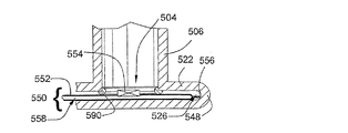
図9に図示されているのは、一方向バルブ要素を介して保管バッグから内在空気を除去するための手持ち式真空500装置の別の実施例である。真空装置500は、熱可塑性材料で製造できる長形ハウジング502も有する。ハウジング502は、ノズル部分506の一端部に流入開口部504を有する。実際に真空化を可能にするため、ハウジング502は、流入開口部504と連通する気流発生ユニット508を包囲する。気流発生ユニット508は電動式であり、ハウジング502の外側に露出したスイッチ520により選択的に作動する。他の実施例において気流発生装置508が例えば手動ポンプなど他の形状をもつものもよいことは理解できるだろう。
Illustrated in FIG. 9 is another embodiment of a
可撓性保管バッグの真空化を容易にするため、真空装置500は流入開口部504のすぐ近くに一体的ブラケット520も含む。上述したように、ブラケット520は、間隙526を設けるように相互に離間した平行な第1および第パネル522,524を有する。第1および第2パネル522,524は適当な形状を有すればよいが、図示された実施例では、パネルは矩形であり、各々が第1長縁部530,532および平行な第2長縁部534,536を有するとともに、各々が第1短縁部540,542および平行な第2短縁部544,546を有する。パネルを一緒に接続するため、U字形部分548が第1長縁部530,532に沿って延在し、これに結合されている。理解できるように、180度U字形部分548は第1および第2パネル522,524を平行に保持するとともに、間隙526のサイズを画定する。
To facilitate evacuation of the flexible storage bag, the
真空装置500の残部にブラケット520を結合するため、第1パネル522はノズル部分506に一体的に形成されるとともにこれと直交する。図10に図示されているように、間隙526に挿入された保管バッグ550に装着された一方向バルブ要素554と接触するように、第1パネル522には流入開口部504が配置されている。U字形部分548と流入開口部504との間の距離に対応する保管バッグ550の縁部556からの所定距離にバルブ要素554が装着されることが好ましい。ゆえに、縁部556がU字形部分548に当接するように保管バッグ500が間隙526に挿入されると、バルブ要素554は流入開口部504と整合する。
The
図9を参照すると、保管バッグ550と真空装置500との間の漏出防止境界面を改善するため、流入開口部504の周縁部にガスケット590が装着される。流入開口部504が円形である図の実施例では、ガスケット590は環状である。ガスケット590は、例えばフォームまたはエラストマ材料を含む適当な材料で製造される。第1および第2パネル522,524の間の間隙526へ一部分が突出するように、ガスケット590は流入開口部504の周縁部に配置される。図10を参照すると、バッグ550が間隙526に挿入されて真空装置が作動すると、バッグの側壁552がガスケット590へ押圧されることにより、ノズル506への周囲の空気の流入を阻止する。さらに吸引すると、バルブ要素554を通して内部空間558から内在空気を吸い出して、保管バッグ550を真空化する。
Referring to FIG. 9, a
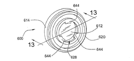
図11,12,13を参照すると、上記タイプの保管バッグに使用するための一方向バルブ要素600は、可動バルブ612と協働してバルブ要素を開閉する剛性バルブボデー610を含む。バルブボデー610は、平行な第1および第2フランジ面620,622の間に延在する円形フランジ部分614を含む。フランジ部分614と同心であり第2フランジ面622から突出するのは、第1および第2フランジ面と平行な平面状ボス面624を終端とする円形ボス部分618である。第2フランジ面622の最外部の環状周縁部が露出したままとなるように、円形ボス部分618はフランジ部分614より直径が短い。バルブボデー610は、ナイロン、HDPE、耐衝撃性ポリスチレン(HIPS)、ポリカーボネート(PC)その他など成形可能な熱可塑性材料などの適当な材料で製造される。
Referring to FIGS. 11, 12, and 13, a one-
バルブボデー610に同心に配置されているのは、カウンタボア628である。カウンタボア628は、第1フランジ面620からボス面624までの一部に延在している。カウンタボア628は、円筒形ボア壁630を画定する。ボス面624までの一部にのみ延在しているため、カウンタボア628は、好ましくは平面状のバルブシート632をバルブボデー610内に形成する。バルブボデー610を通る流体連通を確立するため、バルブシート632には少なくとも一つの孔634が配置されている。実際、図の実施例では、複数の孔634が同心に、円筒形ボア壁630から内側に離間して配置されている。
Concentrically disposed on the
協働するように可動ディスク612を収容するため、ディスクはカウンタボア628に挿入される。したがって、ディスク612は好ましくはカウンタボア628よりも直径が短く、第1フランジ面620とバルブシート632との間におけるカウンタボア628の長さよりかなり短い、第1ディスク面640と第2ディスク面642との間で測定される厚さを有する。ディスク612をカウンタボア630内に保持するため、第1フランジ面620のすぐ近くには径方向内側に延出する複数のフィンガ644が形成されている。ディスク612は、例えば弾性エラストマなど適当な材料で製造される。
To accommodate the
図13を参照すると、カウンタボア630内のディスク612がフィンガ644の付近で移動する時、バルブ要素600は、第1フランジ面620とボス面624との間に空気を連通させる開口配置である。しかし、ディスク612がバルブシート632に隣接することで孔634を被覆すると、バルブ要素600は閉口配置となる。孔634へのディスク612の密封を補助するため、バルブシート632には密封液体が供給される。さらに、ディスク612とバルブシート632とを閉位置で密着させるため、カウンタボア628にフォームまたは他の弾性部材が載置されてもよい。
Referring to FIG. 13, when the
バルブ要素600を第1側壁に装着するため、図12を参照すると、第2フランジ面622の露出した環状周縁部分には接着剤が塗布されている。次に、側壁に配置された孔にボス部分618が配置されて内部空間に入った状態で、バルブ要素600が第1側壁の外面の付近に置かれる。他の実施例では、側壁への装着前に、第1フランジ面など、バルブ要素の他の部分に接着剤が塗布されてもよいことは言うまでもない。
In order to mount the
他の実施例では、一方向バルブ要素が異なる構造を有する。例えば、一方向バルブ要素は、すべて参考としてその全体が取り入れられている特許文献1(米国特許第2,927,722号)と特許文献2(米国特許第2,946,502号)と特許文献3(米国特許第2,821,338号)に開示されたものに類似した可撓性フィルム材料で構成される。
図14に図示されているように、この方式により製造される可撓性の一方向バルブ要素710は、対応の円形弾性上部層724と協働してバルブ要素を開閉する可撓性の円形基部層712を含む。上部および底部層は、例えば可撓性の熱可塑性フィルムなど適当な材料で製造される。基部層712の中心に配置されているのは孔716であり、こうして基部層を環状とする。上部層714が基部層712の上に載置され、孔716の各側に延在する2本の平行なストリップ状接着剤718により基部層に接着されることにより、上部層で孔を被覆して溝を形成する。基部層712は次に、第1側壁702に配置された孔708を被覆するようにリング状接着材730により可撓性バッグ700に接着される。
As shown in FIG. 14, a flexible one-
当該技術の熟練者には理解できるだろうが、バッグ700の側壁702,704が一緒に押圧されると、内部空間706からの空気が穴708と孔716を通過することにより上部層714の一部を基部層712から移動させる。空気はストリップ状接着剤718の間に形成された通路を通って周囲へ放出される。側壁702,704への力が解放されると、弾性上部層714は、孔716を被覆および密封する以前の状態に戻る。空気がバッグへ再流入するのを防止するため、バルブ要素710は二つの層の間にオイル、グリース、潤滑剤などの粘性材料を含んでもよい。ある実施例では、基部層712は剛性シート材料でもよい。
As will be appreciated by those skilled in the art, when the
図15に図示されているのは、可撓性プラスチックバッグ800に装着されるバルブ要素810の別の実施例である。バルブ要素810は、第1端部812と第2端部814とを含む可撓性の熱可塑性フィルムの矩形片である。第1側壁に配置された穴808を被覆および密封するように、第1側壁802にバルブ要素810が装着される。バルブ要素810は、第1および第2端部812,814に対応するように穴808の各側に配置された接着剤パッチ818により、側壁802に装着される。可撓性バッグ800の側壁802,804が一緒に折り畳まれると、穴808を開封するように内部空間806からの空気が可撓性バルブ要素810を移動させる。内部空間806から空気を排出した後、バルブ要素810が再び穴808を被覆および密封する。
Illustrated in FIG. 15 is another embodiment of a
当業者には理解できるように、例えばエラストマスリットバルブ、ダックビルバルブ、チェックバルブなど一方向バルブ要素の他の実施例が、可撓性プラスチックバッグに使用できる。 As can be appreciated by those skilled in the art, other examples of one-way valve elements such as elastomer slit valves, duckbill valves, check valves, etc. can be used for flexible plastic bags.
ゆえに、本発明は、一方向バルブ要素が装着された保管バッグの真空化を改良するためのいくつかの装置と方法を提供する。 The present invention thus provides several devices and methods for improving the evacuation of storage bags fitted with one-way valve elements.
ここに引用された公報、特許出願、特許を含むすべての引例は、各引例が参考として取り入れられていると個別かつ明確に指摘され、その全体がここに記載された場合と同程度に、引例として取り入れられる。 All references, including publications, patent applications and patents cited herein, are individually and clearly pointed out that each reference is incorporated by reference, and to the same extent as if it were described in its entirety. As adopted.
本発明の説明における(特に以下の請求項における)指示語の使用は、他に指示されるか文脈から明らかに否定されない限り、単数と複数の両方を包含すると解釈される。「を包含する」、「を有する」、「を含む」、「を含有する」の語は、他に指摘されない限り、開放用語(つまり「を含むがこれに限定されない」を意味する)と解釈される。値の範囲の記載は、他に指示されない限り、範囲内に包含される個々の値を個別に言及することを省略した方法として機能するものに過ぎず、個々の値は、個別に記載されているかのように明細書に含まれる。ここに記されたすべての方法は、他に指示されるか内容から明らかに否定されない限り、適当な順序で実施できる。ここに提示されたいかなる例または例示的な語(例えば「など」)の使用はすべて、本発明をより明らかにすることのみを意図し、他に請求されないかぎり本発明の範囲に限定を加えるものではない。明細書中のいかなる語も、本発明の実施に不可欠な請求項に記載されていない要素を示すものと解釈されるべきでない。 The use of directives in the description of the invention (especially in the claims below) is to be interpreted as encompassing both the singular and the plural unless otherwise indicated or otherwise clearly denied from context. The terms “including”, “having”, “including”, “including” are interpreted as open terms (ie, including but not limited to) unless otherwise indicated. Is done. The description of a range of values, unless otherwise indicated, serves only as a way of omitting individual references to individual values encompassed within the range, and individual values are described individually. Included in the description as if. All methods described herein can be performed in any suitable order unless otherwise indicated or otherwise clearly denied from the contents. Any use of examples or exemplary words (such as “such as”) presented herein is intended only to make the present invention more apparent and limit the scope of the present invention unless otherwise claimed. is not. No language in the specification should be construed as indicating any non-claimed element essential to the practice of the invention.
発明者らに周知の、発明の実施に最適の態様を含む本発明の好適な実施例がここに記載されている。これらの好適な実施例の変形は、上記の説明を読めば当該技術の通常の技術を有するものには明らかになるだろう。発明者らは、当業者がこのような変形を適宜採用することを期待し、発明者らはここに明記したもの以外の形で発明が実施されることを予期している。したがって、適用法により認められるように、本発明は添付の請求項に記載された主題のすべての変形例と均等物とを含む。さらに、他に指示されないか、内容から明らかに否定されない限り、可能な変形すべてにおける上記の要素の組合せが本発明に包含される。 Preferred embodiments of this invention are described herein, including the best mode known to the inventors for carrying out the invention. Variations of these preferred embodiments will become apparent to those having ordinary skill in the art upon reading the above description. The inventors expect that those skilled in the art will appropriately employ such modifications, and the inventors expect that the invention will be implemented in forms other than those specified herein. Accordingly, as permitted by applicable law, the present invention includes all modifications and equivalents of the subject matter recited in the claims appended hereto. Further, combinations of the above-described elements in all possible variations are encompassed by the invention unless otherwise indicated or otherwise clearly denied from context.
Claims (20)
中に孔が配置された第1フラットパネルと、
前記保管バッグを収容するための間隙を間に設けるように前記第1パネルに接続されたほぼ平行な第2フラットパネルと、
を含むブラケット。 A support bracket to assist in the removal of air from a flexible storage bag having a unidirectional element,
A first flat panel having a hole disposed therein;
A substantially parallel second flat panel connected to the first panel so as to provide a gap for accommodating the storage bag;
Including bracket.
流入開口部を有するハウジングと、
前記ハウジング内で包囲されるとともに前記流入開口部と連通する気流発生ユニットと、
前記流入開口部のすぐ近くで前記ハウジングに結合される第1フラットパネルと、前記保管バッグを収容するための間隙を間に設けるように該第1パネルにほぼ平行に接続された第2フラットパネルとを有する支持ブラケットと、
を含む真空装置。 A vacuum device for removing air from a storage bag having a one-way valve element,
A housing having an inflow opening;
An airflow generating unit enclosed within the housing and in communication with the inflow opening;
A first flat panel coupled to the housing in the immediate vicinity of the inflow opening and a second flat panel connected substantially parallel to the first panel so as to provide a gap for accommodating the storage bag A support bracket having
Including vacuum equipment.
前記内部空間に生鮮食品を挿入する工程と、
前記開口部を密封状態で閉鎖する工程と、
支持ブラケットの平行な第1および第2フラットパネルの間に前記保管バッグを載置する工程と、
前記一方向バルブ要素を前記第1パネルに配置された孔と整合させる工程と、
前記側壁の付近かつ前記バルブ要素の周囲に前記孔を通して真空装置のノズルを載置する工程と、
前記内部空間を真空化する工程と、
を含む、生鮮食品を保管する方法。 A storage bag having a flexible side wall defining an internal space, a sealable opening for making the internal space available, and a one-way valve element attached to the side wall and in communication with the internal space A process of preparing
Inserting fresh food into the internal space;
Closing the opening in a sealed state;
Placing the storage bag between the parallel first and second flat panels of the support bracket;
Aligning the one-way valve element with a hole located in the first panel;
Placing a vacuum device nozzle through the hole in the vicinity of the side wall and around the valve element;
Evacuating the internal space;
A method of storing fresh food, including
第1フラットパネルと、間に間隙を設けるように該第1パネルに接続された平行な第2フラットパネルとを包含する支持ブラケットを用意する工程と、
前記第1および第2フラットパネルの間に前記保管バッグを載置する工程と、
前記一方向バルブ要素を前記第1パネルに配置された孔と整合させる工程と、
前記孔の周囲で前記第1パネルに真空装置のノズルを押圧する工程と、
前記内部空間を真空化する工程と、
を含む方法。 A storage bag comprising a flexible sidewall providing an interior space, a sealable opening for making the interior space available, and a one-way valve element attached to the sidewall and in communication with the interior space A method of evacuation,
Providing a support bracket including a first flat panel and a parallel second flat panel connected to the first panel so as to provide a gap therebetween;
Placing the storage bag between the first and second flat panels;
Aligning the one-way valve element with a hole located in the first panel;
Pressing a nozzle of a vacuum device against the first panel around the hole;
Evacuating the internal space;
Including methods.
ハウジングと、該ハウジングに包囲された気流発生ユニットと、該ハウジングに配置された流入開口部と、該流入開口部のすぐ付近で該ハウジングに結合される第1フラットパネルと該保管バッグを収容するための間隙を間に設けるように該第1パネルに接続された平行な第2フラットパネルとを含む支持ブラケットとを含む、保管バッグから空気を除去するための真空装置を用意する工程と、
前記保管バッグを前記間隙に載置する工程と、
前記一方向バルブ要素を前記流入開口部と整合させる工程と、
前記内部空間を真空化する工程と、
を包含する方法。 A storage bag comprising a flexible side wall defining an interior space, a sealable opening for making the interior space available, and a one-way valve element attached to the side wall and in communication with the interior space A method of evacuating
A housing, an airflow generating unit surrounded by the housing, an inflow opening disposed in the housing, a first flat panel coupled to the housing in the immediate vicinity of the inflow opening, and the storage bag are accommodated Providing a vacuum device for removing air from a storage bag, including a support bracket including a parallel second flat panel connected to the first panel so as to provide a gap therebetween.
Placing the storage bag in the gap;
Aligning the one-way valve element with the inlet opening;
Evacuating the internal space;
Including the method.
前記ハウジングに包囲されるとともに前記流入開口部と連通する気流発生ユニットと、
前記流入開口部の周縁部に配置されたガスケットであって、円形断面を有するガスケットと、
を含む真空装置。 A housing having an inflow opening;
An airflow generating unit surrounded by the housing and in communication with the inflow opening;
A gasket disposed at a peripheral edge of the inflow opening, the gasket having a circular cross section;
Including vacuum equipment.
流入開口部を有するハウジングと、該ハウジングに包囲されるとともに前記流入部と連通する気流発生ユニットと、該流入開口部の周縁部に配置されたガスケットとを含む真空装置と、
の組合せを包含する、食品を保管するためのシステム。 A storage bag comprising a flexible side wall providing an interior space and a one-way valve element attached to the side wall and in communication with the interior space;
A vacuum device including a housing having an inflow opening, an airflow generating unit that is surrounded by the housing and communicates with the inflow, and a gasket disposed at a peripheral edge of the inflow opening;
A system for storing food, including a combination of
Applications Claiming Priority (2)
| Application Number | Priority Date | Filing Date | Title |
|---|---|---|---|
| US68546205P | 2005-05-27 | 2005-05-27 | |
| PCT/US2006/019818 WO2006130384A2 (en) | 2005-05-27 | 2006-05-22 | Device and method for evacuating a storage bag |
Publications (2)
| Publication Number | Publication Date |
|---|---|
| JP2008545588A true JP2008545588A (en) | 2008-12-18 |
| JP2008545588A5 JP2008545588A5 (en) | 2009-06-25 |
Family
ID=37482145
Family Applications (1)
| Application Number | Title | Priority Date | Filing Date |
|---|---|---|---|
| JP2008513605A Pending JP2008545588A (en) | 2005-05-27 | 2006-05-22 | Apparatus and method for evacuating a storage bag |
Country Status (8)
| Country | Link |
|---|---|
| US (1) | US8191469B2 (en) |
| EP (1) | EP1886020A2 (en) |
| JP (1) | JP2008545588A (en) |
| KR (1) | KR20080017051A (en) |
| CN (1) | CN101522528A (en) |
| AU (1) | AU2006252840A1 (en) |
| CA (1) | CA2609540A1 (en) |
| WO (1) | WO2006130384A2 (en) |
Cited By (3)
| Publication number | Priority date | Publication date | Assignee | Title |
|---|---|---|---|---|
| JP2016074460A (en) * | 2014-10-06 | 2016-05-12 | 株式会社ユニバック | Deaeration device in bag on mouth part sealer of bag |
| JP2019500283A (en) * | 2015-10-26 | 2019-01-10 | ロールパック カンパニー リミテッド | Vacuum equipment |
| JP2021066451A (en) * | 2019-10-21 | 2021-04-30 | 株式会社ニシムラ | Intake valve and compression bag including the same |
Families Citing this family (12)
| Publication number | Priority date | Publication date | Assignee | Title |
|---|---|---|---|---|
| US7389629B2 (en) | 2004-07-23 | 2008-06-24 | Reynolds Foil Inc. | Portable vacuum pump for use with reclosable, evacuable containers |
| EP1886020A2 (en) * | 2005-05-27 | 2008-02-13 | The Glad Products Company | Device and method for evacuating a storage bag |
| US8397958B2 (en) | 2010-08-05 | 2013-03-19 | Ds Smith Plastics Limited | Closure valve assembly for a container |
| KR102492584B1 (en) * | 2011-09-30 | 2023-01-27 | 추가이 세이야쿠 가부시키가이샤 | Antigen-binding molecule inducing immune response to target antigen |
| US20150101285A1 (en) * | 2012-01-05 | 2015-04-16 | Rene Eric Vonwiller | Vacuum baggie |
| JP6033126B2 (en) * | 2012-12-22 | 2016-11-30 | 東洋自動機株式会社 | Gas sealing method and gas sealing device for bag with airbag |
| US9615689B2 (en) | 2014-05-20 | 2017-04-11 | Sunbeam Products, Inc. | Food cooking system |
| US10123648B2 (en) * | 2015-12-03 | 2018-11-13 | Robert GODFROID | System and method for cooking |
| KR20180003167A (en) * | 2016-06-30 | 2018-01-09 | 주식회사 롤팩 | Vacuum apparatus |
| US20180080860A1 (en) * | 2016-07-27 | 2018-03-22 | Uop Llc | Method for density measurement using multiple sensors |
| KR20180068072A (en) * | 2016-12-13 | 2018-06-21 | 삼성전자주식회사 | Refrigerator |
| CN114132554B (en) * | 2021-12-01 | 2022-12-27 | 刘惠舒 | Storage device for territory space planning information statistics |
Citations (12)
| Publication number | Priority date | Publication date | Assignee | Title |
|---|---|---|---|---|
| JPS5838288A (en) * | 1981-07-25 | 1983-03-05 | ビ−チヤム・グル−プ・ピ−エルシ− | Beta-lactam antibiotics, manufacture and medicinal composition |
| JPS6078705A (en) * | 1983-10-06 | 1985-05-04 | 株式会社豊田中央研究所 | Ceramics injection molding method |
| JPS62132907A (en) * | 1985-12-05 | 1987-06-16 | Mitsui Toatsu Chem Inc | Method for polymerizing vinyl chloride |
| JPS63162431A (en) * | 1986-12-26 | 1988-07-06 | 小松 正明 | Vacuum packaging method and deaerating section device |
| JPH0144408Y2 (en) * | 1985-05-11 | 1989-12-22 | ||
| JPH0780489B2 (en) * | 1991-10-15 | 1995-08-30 | 日栄電機工業株式会社 | Simple deaeration packaging machine |
| JPH08197470A (en) * | 1995-01-18 | 1996-08-06 | Toyota Auto Body Co Ltd | Vacuum suction cup |
| US5795001A (en) * | 1996-12-18 | 1998-08-18 | Burke; Stephen H. | Vacuum device for handling articles |
| JP3084653B2 (en) * | 1995-01-27 | 2000-09-04 | アラカリア ビイ.ヴイ. | Equipment for packaging of products contained in flexible bags under vacuum |
| JP3341834B2 (en) * | 2000-02-21 | 2002-11-05 | 株式会社サントク | Vacuum storage bag |
| US6520071B1 (en) * | 1999-05-21 | 2003-02-18 | Aracaria B. . | Hand-held suction pump |
| US6543491B1 (en) * | 1999-11-04 | 2003-04-08 | Chung Jing-Yau | Design package for temperature-controlled packaging |
Family Cites Families (58)
| Publication number | Priority date | Publication date | Assignee | Title |
|---|---|---|---|---|
| US2672268A (en) * | 1948-02-25 | 1954-03-16 | William R Mclain | Thermoplastic sealing of bags with vacuum nozzles |
| US2648474A (en) * | 1950-01-04 | 1953-08-11 | Crook Leslie George | Air extractor |
| US2695741A (en) * | 1953-06-16 | 1954-11-30 | Stephen L Haley | Air evacuator for plastic bags |
| US3958693A (en) * | 1975-01-20 | 1976-05-25 | E-Z-Em Company Inc. | Vacuum X-ray envelope |
| US4114668A (en) * | 1975-12-04 | 1978-09-19 | Hickey Christopher Daniel Dowl | Containers having fluid-tight sealing means |
| SE409977B (en) * | 1977-09-16 | 1979-09-17 | Lundblad Tage | DEVICE FOR CREATING PRESSURE IN ONE WITH AN OPENING PROVIDED STORAGE VESSEL |
| GB2008200B (en) * | 1977-11-09 | 1982-10-20 | Emerit Andre A C | Source of vacuum and device for creating and maintaining anegative pressure in an enclosure |
| DE2821852C3 (en) * | 1978-05-19 | 1980-12-18 | Zyliss Zysset Ag, Lyss (Schweiz) | Device for storing perishable goods |
| DE2856021A1 (en) * | 1978-12-23 | 1980-07-03 | Bosch Gmbh Robert | METHOD FOR SEALING A PACKAGE CONTAINER VALVE |
| US4583925A (en) * | 1984-10-03 | 1986-04-22 | Irrometer Company, Inc. | Suction pump |
| US4615361A (en) * | 1985-01-11 | 1986-10-07 | Bartle Sr David C | Evacuating pump |
| US4756422A (en) * | 1985-09-23 | 1988-07-12 | Kristen Hanns J | Plastic bag for vacuum sealing |
| USRE34929E (en) * | 1985-09-23 | 1995-05-09 | Tilia, Inc. | Plastic bag for vacuum sealing |
| US4745730A (en) * | 1986-10-22 | 1988-05-24 | Bartle Sr David C | Method and apparatus for evacuating air from food containers |
| IT1233855B (en) * | 1988-01-22 | 1992-04-21 | Interdibipack Spa | DEVICE FOR THE HERMETIC CLOSURE OF BAGS INTENDED FOR THE VACUUM PACKAGING OF VARIOUS PRODUCTS, IN PARTICULAR FOOD. |
| US4975028A (en) * | 1989-01-13 | 1990-12-04 | Schultz Glen R | Pump apparatus for evacuating containers |
| US5048269A (en) * | 1990-05-09 | 1991-09-17 | Frank Deni | Vacuum sealer |
| US5121590A (en) * | 1990-06-04 | 1992-06-16 | Scanlan Gregory P | Vacuum packing apparatus |
| USD338399S (en) * | 1990-11-20 | 1993-08-17 | Conte Jr Paul R | Vacuum pack freezer bag |
| DK0510360T3 (en) * | 1991-04-03 | 1995-10-30 | Jankovic Milan | Suction device for forming a vacuum in containers |
| US5215445A (en) * | 1992-10-28 | 1993-06-01 | Chen Chia Sing | Handy vacuum pump and heat sealer combination device |
| US5299917A (en) * | 1993-02-16 | 1994-04-05 | Pioneering Concepts Incorporated | Evacuation pump system with check valves for both rigid and flexible containers |
| US5338166A (en) * | 1993-02-16 | 1994-08-16 | Pioneering Concepts Incorporated | Evacuation pump system for both rigid and flexible containers |
| US5480030A (en) * | 1993-12-15 | 1996-01-02 | New West Products, Inc. | Reusable, evacuable enclosure for storage of clothing and the like |
| US5450963A (en) * | 1994-02-22 | 1995-09-19 | Carson; James A. | Air removal device for sealed storage container |
| US5501525A (en) * | 1994-02-24 | 1996-03-26 | Winpak Films, Inc. | Bone-guard bag |
| US5655357A (en) * | 1995-05-02 | 1997-08-12 | Tilia International, Inc. | Exhaust flow rate vacuum sensor |
| US5667627A (en) * | 1995-08-15 | 1997-09-16 | The United States Of America As Represented By The Secretary Of The Navy | Hand held vacuum heat sealer apparatus |
| US5765608A (en) * | 1995-11-08 | 1998-06-16 | Tilia International | Hand held vacuum device |
| US5735395A (en) * | 1996-06-28 | 1998-04-07 | Lo; Luke | Airtight garment hanging bag |
| US5873217A (en) * | 1997-05-09 | 1999-02-23 | Smith; George E. | Vacuum sealing methods and apparatus |
| US6058998A (en) * | 1998-02-12 | 2000-05-09 | Tilia International, Inc. | Plastic bag sealing apparatus with an ultracapacitor discharging power circuit |
| US6256968B1 (en) * | 1999-04-13 | 2001-07-10 | Tilia International | Volumetric vacuum control |
| US6357915B2 (en) * | 1999-08-13 | 2002-03-19 | New West Products, Inc. | Storage bag with one-way air valve |
| KR200190296Y1 (en) * | 2000-02-25 | 2000-07-15 | 안중근 | Bag for vacuum packing apparatus |
| US6581641B2 (en) * | 2001-04-05 | 2003-06-24 | Illinois Tool Works Inc. | One-way valve for use with vacuum pump |
| US6604634B2 (en) * | 2001-07-18 | 2003-08-12 | Fu-Long Su | Receiving bag with enhanced airtight effect |
| US6626092B2 (en) * | 2002-01-22 | 2003-09-30 | Kenneth P. Tarlow | Vacuum producing appliance |
| US20030183331A1 (en) * | 2002-03-26 | 2003-10-02 | Ciambrone David F. | System and method for vacuum bag fabrication |
| US7076929B2 (en) * | 2002-10-04 | 2006-07-18 | Jcs/Thg, Llc | Appliance for vacuum sealing food containers |
| US6971417B2 (en) * | 2002-10-22 | 2005-12-06 | Keystone Manufacturing Co., Inc. | Apparatus for evacuating bags |
| US6964519B2 (en) * | 2003-07-30 | 2005-11-15 | Erkenbrack Kenneth Beresford | Atmospheric and/or differential pressure closure for an evacuable storage container |
| US7021034B2 (en) * | 2003-07-31 | 2006-04-04 | Tilia International, Inc. | Decoupled vacuum packaging appliance |
| US7086211B2 (en) * | 2003-10-08 | 2006-08-08 | Bassett Wade M | Method, apparatus and system for evacuation of containers |
| US7565977B2 (en) * | 2004-02-13 | 2009-07-28 | Leonard Frenkil | Sealable bag with excess air evacuation blocking structure |
| US20050207679A1 (en) * | 2004-03-19 | 2005-09-22 | Armstrong Stephen G | Reclosable bag |
| US7350541B2 (en) * | 2004-03-23 | 2008-04-01 | Illinois Tool Works Inc. | Leakproof one-way valve for use with vacuum attachment |
| US7726880B2 (en) * | 2004-06-29 | 2010-06-01 | The Glad Products Company | Flexible storage bag |
| CA2594559A1 (en) * | 2005-01-12 | 2006-07-20 | Unovo, Inc. | Method and apparatus for evacuating and sealing containers |
| US7597479B2 (en) * | 2005-01-20 | 2009-10-06 | The Glad Products Company | Storage bag with fluid separator |
| US7422369B2 (en) * | 2005-01-20 | 2008-09-09 | The Glad Products Company | Storage bag with fluid separator |
| EP1886020A2 (en) * | 2005-05-27 | 2008-02-13 | The Glad Products Company | Device and method for evacuating a storage bag |
| US7510326B2 (en) * | 2005-07-18 | 2009-03-31 | Highland Champ Corporation | Moisture-proof sealing bag |
| US7513481B2 (en) * | 2005-10-28 | 2009-04-07 | Fu-Long Su | One way valve |
| WO2007143282A2 (en) * | 2006-05-31 | 2007-12-13 | The Glad Products Company | Device and method for evacuating a storage bag |
| US20080028730A1 (en) * | 2006-08-02 | 2008-02-07 | Savicki Alan F | Device and Method For Evacuating A Storage Bag |
| US7874731B2 (en) * | 2007-06-15 | 2011-01-25 | S.C. Johnson Home Storage, Inc. | Valve for a recloseable container |
| WO2009042848A1 (en) * | 2007-09-28 | 2009-04-02 | The Glad Products Company | Evacuable storage bag |
-
2006
- 2006-05-22 EP EP06770888A patent/EP1886020A2/en not_active Withdrawn
- 2006-05-22 CA CA002609540A patent/CA2609540A1/en not_active Abandoned
- 2006-05-22 AU AU2006252840A patent/AU2006252840A1/en not_active Abandoned
- 2006-05-22 US US11/913,055 patent/US8191469B2/en active Active
- 2006-05-22 KR KR1020077030072A patent/KR20080017051A/en not_active Application Discontinuation
- 2006-05-22 CN CNA2006800252203A patent/CN101522528A/en active Pending
- 2006-05-22 JP JP2008513605A patent/JP2008545588A/en active Pending
- 2006-05-22 WO PCT/US2006/019818 patent/WO2006130384A2/en active Application Filing
Patent Citations (12)
| Publication number | Priority date | Publication date | Assignee | Title |
|---|---|---|---|---|
| JPS5838288A (en) * | 1981-07-25 | 1983-03-05 | ビ−チヤム・グル−プ・ピ−エルシ− | Beta-lactam antibiotics, manufacture and medicinal composition |
| JPS6078705A (en) * | 1983-10-06 | 1985-05-04 | 株式会社豊田中央研究所 | Ceramics injection molding method |
| JPH0144408Y2 (en) * | 1985-05-11 | 1989-12-22 | ||
| JPS62132907A (en) * | 1985-12-05 | 1987-06-16 | Mitsui Toatsu Chem Inc | Method for polymerizing vinyl chloride |
| JPS63162431A (en) * | 1986-12-26 | 1988-07-06 | 小松 正明 | Vacuum packaging method and deaerating section device |
| JPH0780489B2 (en) * | 1991-10-15 | 1995-08-30 | 日栄電機工業株式会社 | Simple deaeration packaging machine |
| JPH08197470A (en) * | 1995-01-18 | 1996-08-06 | Toyota Auto Body Co Ltd | Vacuum suction cup |
| JP3084653B2 (en) * | 1995-01-27 | 2000-09-04 | アラカリア ビイ.ヴイ. | Equipment for packaging of products contained in flexible bags under vacuum |
| US5795001A (en) * | 1996-12-18 | 1998-08-18 | Burke; Stephen H. | Vacuum device for handling articles |
| US6520071B1 (en) * | 1999-05-21 | 2003-02-18 | Aracaria B. . | Hand-held suction pump |
| US6543491B1 (en) * | 1999-11-04 | 2003-04-08 | Chung Jing-Yau | Design package for temperature-controlled packaging |
| JP3341834B2 (en) * | 2000-02-21 | 2002-11-05 | 株式会社サントク | Vacuum storage bag |
Cited By (4)
| Publication number | Priority date | Publication date | Assignee | Title |
|---|---|---|---|---|
| JP2016074460A (en) * | 2014-10-06 | 2016-05-12 | 株式会社ユニバック | Deaeration device in bag on mouth part sealer of bag |
| JP2019500283A (en) * | 2015-10-26 | 2019-01-10 | ロールパック カンパニー リミテッド | Vacuum equipment |
| JP2021066451A (en) * | 2019-10-21 | 2021-04-30 | 株式会社ニシムラ | Intake valve and compression bag including the same |
| JP7140392B2 (en) | 2019-10-21 | 2022-09-21 | 株式会社ニシムラ | Intake valve and compression bag with the same |
Also Published As
| Publication number | Publication date |
|---|---|
| CN101522528A (en) | 2009-09-02 |
| CA2609540A1 (en) | 2006-12-07 |
| WO2006130384A3 (en) | 2008-11-13 |
| WO2006130384A8 (en) | 2008-05-02 |
| EP1886020A2 (en) | 2008-02-13 |
| US8191469B2 (en) | 2012-06-05 |
| WO2006130384A2 (en) | 2006-12-07 |
| AU2006252840A1 (en) | 2006-12-07 |
| KR20080017051A (en) | 2008-02-25 |
| US20090007803A1 (en) | 2009-01-08 |
Similar Documents
| Publication | Publication Date | Title |
|---|---|---|
| JP2008545588A (en) | Apparatus and method for evacuating a storage bag | |
| US8061899B2 (en) | Storage bag | |
| AU2003230991B2 (en) | Hose direct canister lid | |
| US20090173038A1 (en) | Device and method for evacuating storage bag | |
| US20080190512A1 (en) | Storage Bag with Evacuation Device | |
| TWM353909U (en) | Ventilation device of sealing jar | |
| JP3193730B2 (en) | Valve structure and restoration prevention body of deaerated packaging bag | |
| US7870708B2 (en) | Device and method for evacuating a storage bag | |
| CN201301042Y (en) | One-way valve and compression bag | |
| KR200389424Y1 (en) | Vacuum packing apparatus with nozzle-housing | |
| CN108792261B (en) | Sealed container, sealed cap and sealed film thereof | |
| KR200403774Y1 (en) | Absorption type cover for vessel | |
| KR20090129290A (en) | Air suction apparatus for vinyl bag | |
| JPH0551039A (en) | Packaging bag | |
| KR20100092093A (en) | Sticker type check valve for vacuum bag and vacuum bag sealing set using the same | |
| KR200403804Y1 (en) | Airtight Vessel Having Device for exhausting air | |
| CN210047813U (en) | Multi-effect exhaust valve for vacuum compression bag pumping and exhausting | |
| KR101178748B1 (en) | vacuum pack for foods packing | |
| WO2014003685A1 (en) | Food container system having lid valve mechanism | |
| KR100485883B1 (en) | Vacuum chamber apparatus provided with sealing means for a vacuum bag by biting it | |
| JP3000847U (en) | Vacuum suction closed container | |
| KR200207013Y1 (en) | vacuum comfirmation apparatus of vacuum preservation container having food | |
| JP2021041992A (en) | Valve device used for compression bag | |
| KR100717155B1 (en) | Airtight Vessel Having Device for exhausting air | |
| KR20100073896A (en) | Air suction apparatus for vinyl bag |
Legal Events
| Date | Code | Title | Description |
|---|---|---|---|
| A521 | Request for written amendment filed |
Free format text: JAPANESE INTERMEDIATE CODE: A523 Effective date: 20090430 |
|
| A621 | Written request for application examination |
Free format text: JAPANESE INTERMEDIATE CODE: A621 Effective date: 20090430 |
|
| A131 | Notification of reasons for refusal |
Free format text: JAPANESE INTERMEDIATE CODE: A131 Effective date: 20110829 |
|
| A02 | Decision of refusal |
Free format text: JAPANESE INTERMEDIATE CODE: A02 Effective date: 20120227 |