JP2008544396A - Portable device having a keyboard for text input - Google Patents
Portable device having a keyboard for text input Download PDFInfo
- Publication number
- JP2008544396A JP2008544396A JP2008518132A JP2008518132A JP2008544396A JP 2008544396 A JP2008544396 A JP 2008544396A JP 2008518132 A JP2008518132 A JP 2008518132A JP 2008518132 A JP2008518132 A JP 2008518132A JP 2008544396 A JP2008544396 A JP 2008544396A
- Authority
- JP
- Japan
- Prior art keywords
- housing part
- housing
- closed position
- housing portion
- protective surface
- Prior art date
- Legal status (The legal status is an assumption and is not a legal conclusion. Google has not performed a legal analysis and makes no representation as to the accuracy of the status listed.)
- Pending
Links
Images


Classifications
-
- G—PHYSICS
- G06—COMPUTING; CALCULATING OR COUNTING
- G06F—ELECTRIC DIGITAL DATA PROCESSING
- G06F1/00—Details not covered by groups G06F3/00 - G06F13/00 and G06F21/00
- G06F1/16—Constructional details or arrangements
- G06F1/1613—Constructional details or arrangements for portable computers
- G06F1/1615—Constructional details or arrangements for portable computers with several enclosures having relative motions, each enclosure supporting at least one I/O or computing function
- G06F1/1624—Constructional details or arrangements for portable computers with several enclosures having relative motions, each enclosure supporting at least one I/O or computing function with sliding enclosures, e.g. sliding keyboard or display
-
- G—PHYSICS
- G06—COMPUTING; CALCULATING OR COUNTING
- G06F—ELECTRIC DIGITAL DATA PROCESSING
- G06F1/00—Details not covered by groups G06F3/00 - G06F13/00 and G06F21/00
- G06F1/16—Constructional details or arrangements
- G06F1/1613—Constructional details or arrangements for portable computers
- G06F1/1615—Constructional details or arrangements for portable computers with several enclosures having relative motions, each enclosure supporting at least one I/O or computing function
- G06F1/1622—Constructional details or arrangements for portable computers with several enclosures having relative motions, each enclosure supporting at least one I/O or computing function with enclosures rotating around an axis perpendicular to the plane they define or with ball-joint coupling, e.g. PDA with display enclosure orientation changeable between portrait and landscape by rotation with respect to a coplanar body enclosure
-
- G—PHYSICS
- G06—COMPUTING; CALCULATING OR COUNTING
- G06F—ELECTRIC DIGITAL DATA PROCESSING
- G06F1/00—Details not covered by groups G06F3/00 - G06F13/00 and G06F21/00
- G06F1/16—Constructional details or arrangements
- G06F1/1613—Constructional details or arrangements for portable computers
- G06F1/1633—Constructional details or arrangements of portable computers not specific to the type of enclosures covered by groups G06F1/1615 - G06F1/1626
- G06F1/1662—Details related to the integrated keyboard
- G06F1/1671—Special purpose buttons or auxiliary keyboards, e.g. retractable mini keypads, keypads or buttons that remain accessible at closed laptop
-
- G—PHYSICS
- G06—COMPUTING; CALCULATING OR COUNTING
- G06F—ELECTRIC DIGITAL DATA PROCESSING
- G06F1/00—Details not covered by groups G06F3/00 - G06F13/00 and G06F21/00
- G06F1/16—Constructional details or arrangements
- G06F1/1613—Constructional details or arrangements for portable computers
- G06F1/1633—Constructional details or arrangements of portable computers not specific to the type of enclosures covered by groups G06F1/1615 - G06F1/1626
- G06F1/1675—Miscellaneous details related to the relative movement between the different enclosures or enclosure parts
- G06F1/1679—Miscellaneous details related to the relative movement between the different enclosures or enclosure parts for locking or maintaining the movable parts of the enclosure in a fixed position, e.g. latching mechanism at the edge of the display in a laptop or for the screen protective cover of a PDA
-
- H—ELECTRICITY
- H04—ELECTRIC COMMUNICATION TECHNIQUE
- H04M—TELEPHONIC COMMUNICATION
- H04M1/00—Substation equipment, e.g. for use by subscribers
- H04M1/02—Constructional features of telephone sets
- H04M1/0202—Portable telephone sets, e.g. cordless phones, mobile phones or bar type handsets
- H04M1/0206—Portable telephones comprising a plurality of mechanically joined movable body parts, e.g. hinged housings
- H04M1/0247—Portable telephones comprising a plurality of mechanically joined movable body parts, e.g. hinged housings comprising more than two body parts
-
- G—PHYSICS
- G06—COMPUTING; CALCULATING OR COUNTING
- G06F—ELECTRIC DIGITAL DATA PROCESSING
- G06F2200/00—Indexing scheme relating to G06F1/04 - G06F1/32
- G06F2200/16—Indexing scheme relating to G06F1/16 - G06F1/18
- G06F2200/161—Indexing scheme relating to constructional details of the monitor
- G06F2200/1614—Image rotation following screen orientation, e.g. switching from landscape to portrait mode
-
- H—ELECTRICITY
- H04—ELECTRIC COMMUNICATION TECHNIQUE
- H04M—TELEPHONIC COMMUNICATION
- H04M1/00—Substation equipment, e.g. for use by subscribers
- H04M1/02—Constructional features of telephone sets
- H04M1/0202—Portable telephone sets, e.g. cordless phones, mobile phones or bar type handsets
- H04M1/0206—Portable telephones comprising a plurality of mechanically joined movable body parts, e.g. hinged housings
- H04M1/0208—Portable telephones comprising a plurality of mechanically joined movable body parts, e.g. hinged housings characterized by the relative motions of the body parts
- H04M1/0225—Rotatable telephones, i.e. the body parts pivoting to an open position around an axis perpendicular to the plane they define in closed position
-
- H—ELECTRICITY
- H04—ELECTRIC COMMUNICATION TECHNIQUE
- H04M—TELEPHONIC COMMUNICATION
- H04M1/00—Substation equipment, e.g. for use by subscribers
- H04M1/02—Constructional features of telephone sets
- H04M1/0202—Portable telephone sets, e.g. cordless phones, mobile phones or bar type handsets
- H04M1/0206—Portable telephones comprising a plurality of mechanically joined movable body parts, e.g. hinged housings
- H04M1/0208—Portable telephones comprising a plurality of mechanically joined movable body parts, e.g. hinged housings characterized by the relative motions of the body parts
- H04M1/0235—Slidable or telescopic telephones, i.e. with a relative translation movement of the body parts; Telephones using a combination of translation and other relative motions of the body parts
- H04M1/0237—Sliding mechanism with one degree of freedom
-
- H—ELECTRICITY
- H04—ELECTRIC COMMUNICATION TECHNIQUE
- H04M—TELEPHONIC COMMUNICATION
- H04M2250/00—Details of telephonic subscriber devices
- H04M2250/18—Details of telephonic subscriber devices including more than one keyboard unit
Abstract
移動通信装置の筐体は第1の筐体部分、第2の筐体部分及び第3の筐体部分を備える。第2の筐体部分は第1の筐体部分に摺動自在に結合され且つ第3の筐体部分に回転自在に結合されている。第1の筐体部分が閉位置から開位置へ動かされることにより、第1の入力装置を含む第1の保護面が露出される。第3の筐体部分が閉位置から開位置へ動かされることにより、第2の入力装置を含む第2の保護面が露出される。 The casing of the mobile communication device includes a first casing portion, a second casing portion, and a third casing portion. The second housing part is slidably coupled to the first housing part and is rotatably coupled to the third housing part. The first protective surface including the first input device is exposed by moving the first housing part from the closed position to the open position. The second protective surface including the second input device is exposed by moving the third housing portion from the closed position to the open position.
Description
本発明は、一般に携帯通信装置に関し、特に、携帯通信装置のキーボード配置に関する。 The present invention relates generally to portable communication devices, and more particularly to keyboard layouts for portable communication devices.
携帯電子装置は現代社会の顧客にとってユビキタス装置として存在感が増している。当該装置には移動電話、パーソナルデジタルアシスタント、カメラ及びオーディオプレーヤが含まれる。異なる機能を実行するためにそのような多くの装置を持ち歩くのは不便であるため、顧客は多様な機能を実行できる多機能装置を求めている。このような傾向に対応して、無線通信技術及び計算技術が1つの装置に集約されるようになった。そのような装置には更にカメラ及び音声演奏記録/再生能力が含まれていてもよい。 Portable electronic devices are gaining presence as ubiquitous devices for customers in modern society. Such devices include mobile phones, personal digital assistants, cameras and audio players. Since it is inconvenient to carry many such devices to perform different functions, customers want multi-function devices that can perform a variety of functions. In response to this trend, wireless communication technology and computing technology have been integrated into one device. Such devices may further include camera and voice performance recording / playback capabilities.
そのような多機能装置を設計する際の問題の1つは、テキスト入力に便利な手段を狭いスペースに配置することである。多くの移動通信装置は、テキスト入力を標準的な携帯電話キーパッドに依存している。電話キーパッドの場合、各キーに複数の文字又は記号が割当てられる。他の装置では、テキスト入力のための手書き認識システムを有するタッチスクリーンを使用する。標準的な携帯電話キーパッド又は手書き認識システムのどちらを使用しても、テキスト入力は遅く、煩雑になりがちである。更に、手書き認識システムは入力の品質により大きく左右される。標準的なQWERTYキーボードは、多くの顧客に対してより便利なテキスト入力手段を提供する。課題は、コンパクトな移動通信装置の中に標準的なQWERTYキーボードを収納することである。 One of the problems in designing such multi-function devices is placing convenient means for text entry in a small space. Many mobile communication devices rely on standard cell phone keypads for text entry. In the case of a telephone keypad, multiple letters or symbols are assigned to each key. Other devices use a touch screen with a handwriting recognition system for text input. Text entry tends to be slow and cumbersome using either standard cell phone keypads or handwriting recognition systems. Furthermore, the handwriting recognition system is greatly influenced by the quality of input. The standard QWERTY keyboard provides a more convenient text input means for many customers. The challenge is to house a standard QWERTY keyboard in a compact mobile communication device.
本発明は、実行されるべきタスクに応じて選択的に露出される複数のユーザインタフェース要素を有するポータブル多機能装置を提供する。携帯装置は3つの筐体部分を具備する。第1の筐体部分は第2の筐体部分に摺動自在に装着され、第3の筐体部分は第2の筐体部分に回転自在に結合される。第1の筐体部分を閉位置から開位置へ摺動することにより、第1のユーザ入力装置を含む第1の保護面が露出される。第3の筐体部分を閉位置から開位置へ回転することにより、第2のユーザ入力装置が露出される。 The present invention provides a portable multifunction device having a plurality of user interface elements that are selectively exposed depending on the task to be performed. The portable device has three housing parts. The first housing portion is slidably attached to the second housing portion, and the third housing portion is rotatably coupled to the second housing portion. By sliding the first housing part from the closed position to the open position, the first protective surface including the first user input device is exposed. The second user input device is exposed by rotating the third housing portion from the closed position to the open position.
一実施形態においては、第1の筐体部分は上部分を構成し、第2の筐体部分は中央部分を構成し、第3の筐体部分は底部分を構成する。第1の保護面は第2の筐体部分に配置される。第1の保護面は、第1の筐体部分が閉位置にある場合に被覆され、第1の筐体部分が開位置にある場合には露出される。第2の保護面は第3の筐体部分に配置される。第2の保護面は、第3の筐体部分が閉位置にある場合に被覆され、第3の筐体部分が開位置にある場合には露出される。本実施形態は、第1の筐体部分が開位置及び閉位置の双方にある場合に見ることができるディスプレイを第1の筐体部分に含んでいてもよい。 In one embodiment, the first housing portion constitutes an upper portion, the second housing portion constitutes a central portion, and the third housing portion constitutes a bottom portion. The first protective surface is disposed on the second housing portion. The first protective surface is covered when the first housing part is in the closed position, and is exposed when the first housing part is in the open position. The second protective surface is disposed on the third housing portion. The second protective surface is covered when the third housing part is in the closed position, and is exposed when the third housing part is in the open position. This embodiment may include a display in the first housing portion that can be seen when the first housing portion is in both the open and closed positions.
別の実施形態においては、第1の筐体部分は底部分を構成し、第2の筐体部分は中央部分を構成し、第3の筐体部分は上部分を構成する。第1の保護面は第1の筐体部分に配置される。第1の保護面は、第1の筐体部分が閉位置にある場合に被覆され、第1の筐体部分が開位置にある場合には露出される。第2の保護面は第2の筐体部分に配置される。第2の保護面は、第3の筐体部分が閉位置にある場合に被覆され、第3の筐体部分が開位置にある場合には露出される。本実施形態は、第3の筐体部分が開位置及び閉位置の双方にある場合に見ることができるディスプレイを第3の筐体部分に含んでいてもよい。 In another embodiment, the first housing portion constitutes the bottom portion, the second housing portion constitutes the central portion, and the third housing portion constitutes the upper portion. The first protective surface is disposed on the first housing portion. The first protective surface is covered when the first housing part is in the closed position, and is exposed when the first housing part is in the open position. The second protective surface is disposed on the second housing portion. The second protective surface is covered when the third housing part is in the closed position, and is exposed when the third housing part is in the open position. This embodiment may include a display in the third housing portion that can be seen when the third housing portion is in both the open position and the closed position.
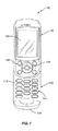
次に図面を参照すると、本発明の一実施形態による移動通信装置が示されており、全体が図中符号100により指し示されている。移動通信装置100は、3つの筐体部分102、106、110から構成される筐体を備える。
Referring now to the drawings, there is shown a mobile communication device according to one embodiment of the present invention, indicated generally by the
本明細書においては上部分と呼ばれる第1の筐体部分102は、上面104に配置された電子ディスプレイ150、ジョイスティック制御部146及び複数のファンクションキー148を含む。ディスプレイ150は従来の液晶ディスプレイ又はタッチスクリーンディスプレイから構成されていてもよい。ユーザは、ディスプレイ150において状態情報、メニューオプション及びアプリケーションデータなどの情報を見ることができる。ジョイスティック制御部146及びファンクションキー148は、移動通信装置100の動作を制御するために使用されてもよい。ユーザはジョイスティック制御部146を使用して、ディスプレイ150に提示されたメニューをナビゲートし、ディスプレイ上でポインタを移動し、ディスプレイ150に提示されたメニュー項目及び他の項目を選択することができる。ファンクションキー148には、対応するファンクションキー148を押下することにより起動又はイネーブルされる機能が割当てられていてもよい。例えば、デフォルトモードにある場合、ファンクションキー148は発呼を開始及び/又は終了するために使用されてもよい。ファンクションキー148に割当てられる特定の機能は動作モードに応じて変更されてもよい。
The
図2に示すように、中央部分と呼ばれる筐体部分106は、上面108にQWERTYキーボード142を備える。QWERTYキーボード142は、従来のコンピュータキーボードのようなテキスト入力及び一般的な計算用途に使用される。QWERTYキーボード142は移動通信装置100の長手方向に配列される。QWERTYキーボード142が図2に示されるように展開された場合、移動通信装置100のCPU120は、表示モードを通常の縦長モードから横長モードに変更するための信号を発生する。
As shown in FIG. 2, the
図3に示すように、底部分と呼ばれる第3の筐体部分110は、上面112に標準的な電話キーパッド144を備える。電話キーパッド144は電話をかける、電話に出る及び電話を切るなどの標準的な電話動作を実行するために使用される。電話キーパッド144が図3に示されるような展開位置にある場合、CPU120はディスプレイ150の表示モードを通常の縦長モードに設定するための制御信号を発生する。
As shown in FIG. 3, the
筐体の上部分102が図1に示されるような閉位置から図2に示されるような開位置へ上方に摺動するように、上部分102は中央部分106に摺動自在に結合されている。上部分102は、図4に示されるように下方へ突出する側壁又はリップ114を備える。側壁114は、中央部分106に形成された軌道116と係合している。側壁114及び軌道116は、中央部分106に対して上部分102を摺動させながら上部分102を中央部分106に保持するように構成されている。上部分102は、図1に示される閉位置と図2に示される開位置との間で摺動する。閉位置にあるとき、中央部分106の上面108は被覆される。開位置へ動かされると、中央部分106の上面108は露出されるので、QWERTYキーボード142を操作することができる。開示される実施形態においては、上部分102及び中央部分106の大きさ及び形状は一致している。従って、閉位置にあるとき、中央部分106の上部分108は全て被覆される。他の実施形態においては、上部分102が閉位置にある場合でも中央部分106の上面108の少なくとも一部が露出された状態となるように、上部分102は中央部分106より小さく構成される。そのような実施形態においては、キーボード142の一部は露出していてもよい。一例として、上部分102が閉位置にある場合、キーボード142の一番下の列のキーが見えていてもよい。第1の筐体部分が開位置及び閉位置のどちらにあっても、ディスプレイ150は見えている。
The
底部分110が閉位置(図1参照)と開位置(図3参照)との間で軸Aに関して回転するように、中央部分106は底部分110に回転自在に結合されている。閉位置にあるとき、中央部分106は底部分110の上面112の少なくとも一部を被覆する。開位置にあるとき、電話キーパッド144を操作できるように、上面112の少なくとも一部は露出される。開示される実施形態においては、底部分110が閉位置にある場合に上面112全体が被覆されるように、中央部分106及び底部分110の大きさ及び形状は一致している。他の実施形態においては、底部分110が閉位置へ移動された場合に上面112の一部が露出された状態となるように、中央部分106は底部分110より小さく構成される。例えば、底部分110が閉位置へ移動された場合、キーパッド114の一番下の列のキーが露出された状態にあり、操作可能となっていてもよい。
図5〜図8は、本発明による別の移動通信装置100を示す。本実施形態においては、上部分102は中央部分106に対して回動し、底部分110は中央部分106に対して摺動する。従って、QWERTYキーボード142は底部分110に配置され、電話キーパッド144は中央部分106に配置される。本発明の他の全ての面は先に説明した通りである。
5 to 8 show another
いくつかの実施形態においては、図1〜図4に示される実施形態において底部分110を中央部分106に対して回動させる場合に、上部分102が偶発的に摺動するのを防止するために、第1のロック機構150が設けられてもよい。同様に、上部分102を閉位置から開位置へ摺動させる場合に、底部分110が中央部分106に対して回転するのを防止するために、第2のロック機構170が設けられてもよい。第1のロック機構150は、図5〜図8に示される実施形態において上部分102を中央部分に対して回動させる場合に底部分110が偶発的に摺動するのを防止するために設けられてもよく、第2のロック機構170は、底部分110を閉位置から開位置へ摺動させる場合に上部分102が中央部分106に対して回転するのを防止するために設けられてもよいことは理解されるであろう。
In some embodiments, to prevent accidental sliding of the
図9A〜図9Cは、第1のロック機構150の一実施形態を示す。図9A〜図9Cは、3つの異なる位置にあるロック機構を示す。各図の上に示される図は、ロック機構150の横断面図である。下の図は、ロック機構150の縦断面図である。
9A-9C show one embodiment of the
ロック機構150は、中央部分106に固着されたロック部材152を具備する。ロック部材152は複数の側方突起154及び軸方向孔156を備える。ロック部材152は、上部分102の底面にあるT字形溝162と係合している。T字形溝162の端部は切欠き164を備える。ロック部材152の軸方向孔156の中には圧縮ばね158及び滑り軸受160が配置されている。ばね158は軸受部材160をT字形溝162の上部分に圧接させる。図9Aは、上部分102が閉位置にある場合のロック機構150を示している。この位置にあるとき、ばね158は上部分102に上向きの力を加え、側方突起154を案内溝162の切欠き164に当接させることにより、上部分102が中央部分106に対して摺動するのを防止している。上部分102のロックを解除する場合には、ユーザは上部分102に下方横向きの力を加える。上部分102を押下げると、図9Bに示されるように、ロック部材152の側方突起154は案内溝162の切欠き164から外れる。図9Cに示されるように、横向きの力によって、上部分102は中央部分106に対して摺動する。上部分102を閉位置に戻すと、ばね156は上部分を押上げ、図5に示されるように、ロック部材152の側方突起154を案内溝162の端部切欠き164に再び当接させる。
The
図10は、中央部分106に対する底部分110の回転を防止する第2のロック機構170を示している。ロック機構170は、回動部材172に関して回転する1対の円板形ロック部材174を備える。回動部材172は回転軸Aを規定している。ロック部材174は鋸歯形面176を備える。回動部材172の周囲に配置されたばね178は、図6に示されるようにロック部材174を互いに離間するように偏向する。ロック部材174が互いに離間していれば、中央部分196は底部分110に対して自在に回転することができる。中央部分106に下向きの圧力が加えられ且つ/又は底部分110に上向きの圧力が加えられると、ロック部材174は互いに係合し、それにより、部分106及び110の回転を防止することができる。
FIG. 10 shows a
上部分102に下向きの圧力が加えられた場合、第1のロック機構150におけるばね158のばね定数が第2のロック機構170におけるばね178のばね定数より大きければ、その力はばね156を介して中央部分106へ伝達されることが当業者には理解されるであろう。ばね定数を慎重に選択することにより、第1のロック機構150の係合が解除される前に第2のロック機構170が係合することを保証できる。従って、第1のロック機構150の係合を解除するのに十分な力が加えられれば、中央部分106に対する底部分110の回転は防止される。
When downward pressure is applied to the
図11は、移動通信装置100の機能要素を示す。機能要素は、中央処理装置120、メモリ122、音声処理回路124、トランシーバ130、カメラモジュール132及びユーザインタフェース140を含む。中央処理装置120は、メモリ122に格納されたプログラム命令に従って移動通信装置100の動作全般を制御する。メモリ122は、動作に必要とされるプログラム命令及びデータを格納する。音声処理回路124は、マイクロホン126を介して入力され且つスピーカ128を介して出力される音声信号を処理する。マイクロホン126は音響信号を電気音声信号に変換する。スピーカ128は電気音声信号を音響信号に変換する。トランシーバ130は遠隔装置との通信を可能にする。例えば、トランシーバ130は標準形セルラトランシーバ、又はBluetoothトランシーバなどの狭域無線インタフェースなどを具備していてもよい。カメラモジュール132は静止画像及び/又はビデオ画像を撮像するために使用され、それらの画像はメモリ122に格納されるか又はトランシーバ130を介して遠隔者へ送信されてもよい。ユーザインタフェース140は、前述のようにユーザとCPU120との間のインタフェースとして動作する。
FIG. 11 shows functional elements of the
本発明が本発明の範囲及び本質的特徴から逸脱せずに本明細書中に記載された方法以外の他の特定の方法で実施されてもよいことは言うまでもない。従って、上記の実施形態は、あらゆる面において限定的な意味を持たない例として考慮されるべきであり、添付の請求の範囲の意味及びそれと等価な範囲内に入る全ての変更は本発明に含まれるものとする。 It will be appreciated that the present invention may be practiced in other specific ways than those described herein without departing from the scope and essential characteristics of the invention. Therefore, the above embodiments should be considered as examples having no limitative meaning in all aspects, and all modifications that fall within the meaning of the appended claims and the equivalent scope thereof are included in the present invention. Shall be.
Claims (26)
第2の筐体部分(106)であって、前記第1の筐体(102、110)が閉位置と開位置との間で該第2の筐体部分(106)に対して摺動するように前記第1の筐体部分(102、110)に摺動自在に結合され、前記第1の筐体部分(102、110)が閉位置から開位置へ動かされることにより、前記第1の筐体部分(102、110)が閉位置にある場合には少なくとも一部が被覆されている第1の保護面(108)が露出される第2の筐体部分(106)と、
閉位置と開位置との間で回転するように前記第2の筐体部分(106)に回動自在に結合される第3の筐体部分(110、102)であって、該第3の筐体部分(110、102)が閉位置から開位置へ動かされることにより、該第3の筐体部分(110、102)が閉位置にある場合には少なくとも一部が被覆されている第2の保護面(112)が露出される第3の筐体部分(110、102)と
を備えることを特徴とする携帯装置。 A first housing portion (102, 110);
A second housing part (106), wherein the first housing (102, 110) slides relative to the second housing part (106) between a closed position and an open position; The first housing part (102, 110) is slidably coupled to the first housing part (102, 110), and the first housing part (102, 110) is moved from the closed position to the open position, thereby A second housing portion (106) exposing the first protective surface (108) at least partially covered when the housing portions (102, 110) are in the closed position;
A third housing part (110, 102) rotatably coupled to the second housing part (106) for rotation between a closed position and an open position, When the housing portion (110, 102) is moved from the closed position to the open position, the second housing portion is covered at least partially when the third housing portion (110, 102) is in the closed position. And a third housing part (110, 102) from which the protective surface (112) is exposed.
第1の保護面(108)に第1の入力装置(142)を配置する工程と、
第1の筐体部分(102、110)を第2の筐体部分(106)に対して閉位置から開位置へ摺動することにより、前記第1の入力装置を露出する工程と、
第2の保護面(112)に第2の入力装置(144)を配置する工程と、
第3の筐体部分(110、102)を前記第2の筐体部分(106)に対して閉位置から開位置へ回転することにより、前記第2の入力装置(144)を露出する工程と
を備えることを特徴とする方法。 A method for providing a user interface to a portable device comprising:
Disposing the first input device (142) on the first protective surface (108);
Exposing the first input device by sliding the first housing portion (102, 110) relative to the second housing portion (106) from a closed position to an open position;
Placing the second input device (144) on the second protective surface (112);
Exposing the second input device (144) by rotating a third housing part (110, 102) from a closed position to an open position relative to the second housing part (106); A method comprising the steps of:
Applications Claiming Priority (2)
| Application Number | Priority Date | Filing Date | Title |
|---|---|---|---|
| US11/166,944 US20060293093A1 (en) | 2005-06-24 | 2005-06-24 | Portable device with text-entry keyboard |
| PCT/US2006/008836 WO2007001516A1 (en) | 2005-06-24 | 2006-03-13 | Portable device with text-entry keyboard |
Publications (2)
| Publication Number | Publication Date |
|---|---|
| JP2008544396A true JP2008544396A (en) | 2008-12-04 |
| JP2008544396A5 JP2008544396A5 (en) | 2009-03-12 |
Family
ID=36576689
Family Applications (1)
| Application Number | Title | Priority Date | Filing Date |
|---|---|---|---|
| JP2008518132A Pending JP2008544396A (en) | 2005-06-24 | 2006-03-13 | Portable device having a keyboard for text input |
Country Status (5)
| Country | Link |
|---|---|
| US (1) | US20060293093A1 (en) |
| EP (1) | EP1896921A1 (en) |
| JP (1) | JP2008544396A (en) |
| CN (1) | CN101203822A (en) |
| WO (1) | WO2007001516A1 (en) |
Cited By (3)
| Publication number | Priority date | Publication date | Assignee | Title |
|---|---|---|---|---|
| JP2009003614A (en) * | 2007-06-20 | 2009-01-08 | Sony Corp | Slide mechanism and electronic apparatus |
| JP2016170539A (en) * | 2015-03-11 | 2016-09-23 | Necパーソナルコンピュータ株式会社 | Information processing apparatus |
| KR101983504B1 (en) * | 2018-08-29 | 2019-05-29 | 최태홍 | Smart phone case combination keyboard for blind |
Families Citing this family (15)
| Publication number | Priority date | Publication date | Assignee | Title |
|---|---|---|---|---|
| KR100704031B1 (en) * | 2004-04-29 | 2007-04-04 | 삼성전자주식회사 | Double sliding-type portable communication device |
| KR100616197B1 (en) * | 2004-08-24 | 2006-08-25 | 삼성전자주식회사 | Sliding apparatus for double sliding-type portable communication device |
| US20070142101A1 (en) * | 2005-08-23 | 2007-06-21 | Sudhir Seshagiri | Mobile electronic device having a rotatable keypad |
| US9244602B2 (en) * | 2005-08-24 | 2016-01-26 | Lg Electronics Inc. | Mobile communications terminal having a touch input unit and controlling method thereof |
| KR100652755B1 (en) * | 2005-08-30 | 2006-12-01 | 엘지전자 주식회사 | Portable phone of a touching and pushing type able to be backlighted |
| US7825907B2 (en) * | 2005-08-30 | 2010-11-02 | Lg Electronics Inc. | Touch key assembly for a mobile terminal |
| ES2444648T3 (en) * | 2005-08-30 | 2014-02-26 | Lg Electronics Inc. | Touch key set for a mobile terminal |
| US8920343B2 (en) | 2006-03-23 | 2014-12-30 | Michael Edward Sabatino | Apparatus for acquiring and processing of physiological auditory signals |
| KR100713479B1 (en) * | 2006-06-08 | 2007-05-02 | 삼성전자주식회사 | Mobile phone and sliding/swing-cradling apparatus thereof |
| US8101529B2 (en) * | 2007-02-15 | 2012-01-24 | Nec Corporation | Carbon nanotube resistor, semiconductor device, and manufacturing method thereof |
| TW200917929A (en) * | 2007-10-05 | 2009-04-16 | Qisda Corp | Bilateral sliding module and the electronic device for using the same |
| JP2009284018A (en) * | 2008-05-19 | 2009-12-03 | Fujitsu Ltd | Information terminal |
| US20100090959A1 (en) * | 2008-10-14 | 2010-04-15 | Sony Ericsson Mobile Communications Ab | Forming a keyboard from a combination of keys displayed on a touch sensitive display and on a separate keypad |
| US8391935B2 (en) * | 2009-03-23 | 2013-03-05 | T-Mobile Usa, Inc. | Multifunction mobile device having a movable element, such as a display, and associated functions |
| US20100331063A1 (en) * | 2009-06-30 | 2010-12-30 | Nokia Corporation | Method and apparatus for a sliding display |
Citations (4)
| Publication number | Priority date | Publication date | Assignee | Title |
|---|---|---|---|---|
| JP2003234809A (en) * | 2002-02-07 | 2003-08-22 | Toshiba Corp | Portable information terminal |
| JP2004235897A (en) * | 2003-01-29 | 2004-08-19 | Kato Electrical Mach Co Ltd | Portable telephone and slide mechanism |
| JP2005069468A (en) * | 2003-08-01 | 2005-03-17 | Strawberry Corporation | Hinge device and electronic equipment using hinge device |
| WO2005052777A2 (en) * | 2003-11-19 | 2005-06-09 | Qualcomm Incoporated | A portable device with versatile keyboards |
Family Cites Families (7)
| Publication number | Priority date | Publication date | Assignee | Title |
|---|---|---|---|---|
| US5584054A (en) * | 1994-07-18 | 1996-12-10 | Motorola, Inc. | Communication device having a movable front cover for exposing a touch sensitive display |
| GB2359963B (en) * | 1999-10-15 | 2004-02-11 | Matsushita Electric Ind Co Ltd | Portable telephone apparatus and control method thereof |
| US6665173B2 (en) * | 1999-12-20 | 2003-12-16 | Wireless Agents, Llc | Physical configuration of a hand-held electronic communication device |
| FI116345B (en) * | 2000-12-19 | 2005-10-31 | Nokia Corp | Portable electronic devices |
| KR100465961B1 (en) * | 2002-07-23 | 2005-01-13 | 삼성전자주식회사 | Portable wireless terminal with hinge device |
| GB2407933B (en) * | 2003-11-06 | 2006-03-08 | Inventec Appliances Corp | Hand-held communication electronic apparatus having two slidable keypads |
| US7907121B2 (en) * | 2003-11-19 | 2011-03-15 | Qualcomm Incorporated | Portable device with versatile keyboard |
-
2005
- 2005-06-24 US US11/166,944 patent/US20060293093A1/en not_active Abandoned
-
2006
- 2006-03-13 CN CNA2006800221366A patent/CN101203822A/en active Pending
- 2006-03-13 JP JP2008518132A patent/JP2008544396A/en active Pending
- 2006-03-13 WO PCT/US2006/008836 patent/WO2007001516A1/en active Application Filing
- 2006-03-13 EP EP06737954A patent/EP1896921A1/en not_active Withdrawn
Patent Citations (5)
| Publication number | Priority date | Publication date | Assignee | Title |
|---|---|---|---|---|
| JP2003234809A (en) * | 2002-02-07 | 2003-08-22 | Toshiba Corp | Portable information terminal |
| JP2004235897A (en) * | 2003-01-29 | 2004-08-19 | Kato Electrical Mach Co Ltd | Portable telephone and slide mechanism |
| JP2005069468A (en) * | 2003-08-01 | 2005-03-17 | Strawberry Corporation | Hinge device and electronic equipment using hinge device |
| WO2005052777A2 (en) * | 2003-11-19 | 2005-06-09 | Qualcomm Incoporated | A portable device with versatile keyboards |
| JP2007518155A (en) * | 2003-11-19 | 2007-07-05 | クゥアルコム・インコーポレイテッド | Portable device with universal keyboard |
Cited By (5)
| Publication number | Priority date | Publication date | Assignee | Title |
|---|---|---|---|---|
| JP2009003614A (en) * | 2007-06-20 | 2009-01-08 | Sony Corp | Slide mechanism and electronic apparatus |
| JP2016170539A (en) * | 2015-03-11 | 2016-09-23 | Necパーソナルコンピュータ株式会社 | Information processing apparatus |
| KR101983504B1 (en) * | 2018-08-29 | 2019-05-29 | 최태홍 | Smart phone case combination keyboard for blind |
| WO2020045832A1 (en) * | 2018-08-29 | 2020-03-05 | 최태홍 | Combined smartphone case and keyboard for visually impaired |
| US11310358B2 (en) | 2018-08-29 | 2022-04-19 | Tai Hong CHOI | Smart phone case combination keyboard for blind |
Also Published As
| Publication number | Publication date |
|---|---|
| CN101203822A (en) | 2008-06-18 |
| US20060293093A1 (en) | 2006-12-28 |
| EP1896921A1 (en) | 2008-03-12 |
| WO2007001516A1 (en) | 2007-01-04 |
Similar Documents
| Publication | Publication Date | Title |
|---|---|---|
| JP2008544396A (en) | Portable device having a keyboard for text input | |
| JP5130296B2 (en) | Electronic device and input interface switching method | |
| JP4828632B2 (en) | Housing configuration for portable equipment with display | |
| JP4663925B2 (en) | Foldable portable electronic device and handle device for foldable portable electronic device | |
| US7068259B2 (en) | Key data input device and mobile communication terminal using the same | |
| JP2007179525A (en) | Portable electronic equipment | |
| KR20040083788A (en) | Portable communication terminal capable of operating program using a gesture command and program operating method using thereof | |
| JP2003319044A (en) | Cellular phone | |
| EP2665240B1 (en) | Mobile terminal including a sliding door for a socket | |
| EP1638299A1 (en) | Hand-held communication device with two housings and a keypad accessible both in the open and the closed position | |
| US20080318617A1 (en) | Appearance adaptable keypad for a handheld communication device | |
| JP5968567B1 (en) | mobile phone | |
| WO2007078256A1 (en) | A keypad arrangement for a mobile phone and the like | |
| JP5363890B2 (en) | Mobile phone | |
| JPWO2007072664A1 (en) | Mobile communication terminal, function menu display method used therefor, and program thereof | |
| KR100640402B1 (en) | Portable terminal capable of variably displaying in difference area with screen electronic touch interfaces window according to input interface mode | |
| JP2002358155A (en) | Input device | |
| JP2004297648A (en) | Portable telephone set and program for making computer perform menu display thereof | |
| WO2018154332A1 (en) | A clamshell form-factor portable personal electronic computer | |
| EP2006761B1 (en) | Appearance adaptable keypad for a handheld communication device | |
| KR100605863B1 (en) | Poterble terminal and method capable of quickly seleting a menu | |
| JP4288204B2 (en) | Mobile phone | |
| KR101474437B1 (en) | Portable terminal | |
| KR100663554B1 (en) | Input device for portable terminal | |
| JP5452899B2 (en) | Function assignment method for portable terminal and operation buttons |
Legal Events
| Date | Code | Title | Description |
|---|---|---|---|
| A521 | Written amendment |
Free format text: JAPANESE INTERMEDIATE CODE: A523 Effective date: 20090122 |
|
| A621 | Written request for application examination |
Free format text: JAPANESE INTERMEDIATE CODE: A621 Effective date: 20090122 |
|
| A02 | Decision of refusal |
Free format text: JAPANESE INTERMEDIATE CODE: A02 Effective date: 20110905 |