JP2008539831A - Spinal stabilization implant - Google Patents
Spinal stabilization implant Download PDFInfo
- Publication number
- JP2008539831A JP2008539831A JP2008509279A JP2008509279A JP2008539831A JP 2008539831 A JP2008539831 A JP 2008539831A JP 2008509279 A JP2008509279 A JP 2008509279A JP 2008509279 A JP2008509279 A JP 2008509279A JP 2008539831 A JP2008539831 A JP 2008539831A
- Authority
- JP
- Japan
- Prior art keywords
- implant
- anchor
- bone
- vertebra
- anchor plates
- Prior art date
- Legal status (The legal status is an assumption and is not a legal conclusion. Google has not performed a legal analysis and makes no representation as to the accuracy of the status listed.)
- Pending
Links
Images


Classifications
-
- A—HUMAN NECESSITIES
- A61—MEDICAL OR VETERINARY SCIENCE; HYGIENE
- A61B—DIAGNOSIS; SURGERY; IDENTIFICATION
- A61B17/00—Surgical instruments, devices or methods, e.g. tourniquets
- A61B17/56—Surgical instruments or methods for treatment of bones or joints; Devices specially adapted therefor
- A61B17/58—Surgical instruments or methods for treatment of bones or joints; Devices specially adapted therefor for osteosynthesis, e.g. bone plates, screws, setting implements or the like
- A61B17/68—Internal fixation devices, including fasteners and spinal fixators, even if a part thereof projects from the skin
- A61B17/80—Cortical plates, i.e. bone plates; Instruments for holding or positioning cortical plates, or for compressing bones attached to cortical plates
-
- A—HUMAN NECESSITIES
- A61—MEDICAL OR VETERINARY SCIENCE; HYGIENE
- A61B—DIAGNOSIS; SURGERY; IDENTIFICATION
- A61B17/00—Surgical instruments, devices or methods, e.g. tourniquets
- A61B17/56—Surgical instruments or methods for treatment of bones or joints; Devices specially adapted therefor
- A61B17/58—Surgical instruments or methods for treatment of bones or joints; Devices specially adapted therefor for osteosynthesis, e.g. bone plates, screws, setting implements or the like
- A61B17/68—Internal fixation devices, including fasteners and spinal fixators, even if a part thereof projects from the skin
- A61B17/70—Spinal positioners or stabilisers ; Bone stabilisers comprising fluid filler in an implant
- A61B17/7062—Devices acting on, attached to, or simulating the effect of, vertebral processes, vertebral facets or ribs ; Tools for such devices
-
- A—HUMAN NECESSITIES
- A61—MEDICAL OR VETERINARY SCIENCE; HYGIENE
- A61B—DIAGNOSIS; SURGERY; IDENTIFICATION
- A61B17/00—Surgical instruments, devices or methods, e.g. tourniquets
- A61B17/56—Surgical instruments or methods for treatment of bones or joints; Devices specially adapted therefor
- A61B17/58—Surgical instruments or methods for treatment of bones or joints; Devices specially adapted therefor for osteosynthesis, e.g. bone plates, screws, setting implements or the like
- A61B17/68—Internal fixation devices, including fasteners and spinal fixators, even if a part thereof projects from the skin
- A61B17/80—Cortical plates, i.e. bone plates; Instruments for holding or positioning cortical plates, or for compressing bones attached to cortical plates
- A61B17/8033—Cortical plates, i.e. bone plates; Instruments for holding or positioning cortical plates, or for compressing bones attached to cortical plates having indirect contact with screw heads, or having contact with screw heads maintained with the aid of additional components, e.g. nuts, wedges or head covers
- A61B17/8042—Cortical plates, i.e. bone plates; Instruments for holding or positioning cortical plates, or for compressing bones attached to cortical plates having indirect contact with screw heads, or having contact with screw heads maintained with the aid of additional components, e.g. nuts, wedges or head covers the additional component being a cover over the screw head
-
- A—HUMAN NECESSITIES
- A61—MEDICAL OR VETERINARY SCIENCE; HYGIENE
- A61F—FILTERS IMPLANTABLE INTO BLOOD VESSELS; PROSTHESES; DEVICES PROVIDING PATENCY TO, OR PREVENTING COLLAPSING OF, TUBULAR STRUCTURES OF THE BODY, e.g. STENTS; ORTHOPAEDIC, NURSING OR CONTRACEPTIVE DEVICES; FOMENTATION; TREATMENT OR PROTECTION OF EYES OR EARS; BANDAGES, DRESSINGS OR ABSORBENT PADS; FIRST-AID KITS
- A61F2/00—Filters implantable into blood vessels; Prostheses, i.e. artificial substitutes or replacements for parts of the body; Appliances for connecting them with the body; Devices providing patency to, or preventing collapsing of, tubular structures of the body, e.g. stents
- A61F2/02—Prostheses implantable into the body
- A61F2/30—Joints
- A61F2/44—Joints for the spine, e.g. vertebrae, spinal discs
-
- A—HUMAN NECESSITIES
- A61—MEDICAL OR VETERINARY SCIENCE; HYGIENE
- A61B—DIAGNOSIS; SURGERY; IDENTIFICATION
- A61B17/00—Surgical instruments, devices or methods, e.g. tourniquets
- A61B17/56—Surgical instruments or methods for treatment of bones or joints; Devices specially adapted therefor
- A61B17/58—Surgical instruments or methods for treatment of bones or joints; Devices specially adapted therefor for osteosynthesis, e.g. bone plates, screws, setting implements or the like
- A61B17/68—Internal fixation devices, including fasteners and spinal fixators, even if a part thereof projects from the skin
- A61B17/70—Spinal positioners or stabilisers ; Bone stabilisers comprising fluid filler in an implant
- A61B17/7062—Devices acting on, attached to, or simulating the effect of, vertebral processes, vertebral facets or ribs ; Tools for such devices
- A61B17/7064—Devices acting on, attached to, or simulating the effect of, vertebral facets; Tools therefor
-
- A—HUMAN NECESSITIES
- A61—MEDICAL OR VETERINARY SCIENCE; HYGIENE
- A61F—FILTERS IMPLANTABLE INTO BLOOD VESSELS; PROSTHESES; DEVICES PROVIDING PATENCY TO, OR PREVENTING COLLAPSING OF, TUBULAR STRUCTURES OF THE BODY, e.g. STENTS; ORTHOPAEDIC, NURSING OR CONTRACEPTIVE DEVICES; FOMENTATION; TREATMENT OR PROTECTION OF EYES OR EARS; BANDAGES, DRESSINGS OR ABSORBENT PADS; FIRST-AID KITS
- A61F2/00—Filters implantable into blood vessels; Prostheses, i.e. artificial substitutes or replacements for parts of the body; Appliances for connecting them with the body; Devices providing patency to, or preventing collapsing of, tubular structures of the body, e.g. stents
- A61F2/02—Prostheses implantable into the body
- A61F2/30—Joints
- A61F2002/30001—Additional features of subject-matter classified in A61F2/28, A61F2/30 and subgroups thereof
- A61F2002/30316—The prosthesis having different structural features at different locations within the same prosthesis; Connections between prosthetic parts; Special structural features of bone or joint prostheses not otherwise provided for
- A61F2002/30329—Connections or couplings between prosthetic parts, e.g. between modular parts; Connecting elements
- A61F2002/30462—Connections or couplings between prosthetic parts, e.g. between modular parts; Connecting elements retained or tied with a rope, string, thread, wire or cable
-
- A—HUMAN NECESSITIES
- A61—MEDICAL OR VETERINARY SCIENCE; HYGIENE
- A61F—FILTERS IMPLANTABLE INTO BLOOD VESSELS; PROSTHESES; DEVICES PROVIDING PATENCY TO, OR PREVENTING COLLAPSING OF, TUBULAR STRUCTURES OF THE BODY, e.g. STENTS; ORTHOPAEDIC, NURSING OR CONTRACEPTIVE DEVICES; FOMENTATION; TREATMENT OR PROTECTION OF EYES OR EARS; BANDAGES, DRESSINGS OR ABSORBENT PADS; FIRST-AID KITS
- A61F2/00—Filters implantable into blood vessels; Prostheses, i.e. artificial substitutes or replacements for parts of the body; Appliances for connecting them with the body; Devices providing patency to, or preventing collapsing of, tubular structures of the body, e.g. stents
- A61F2/02—Prostheses implantable into the body
- A61F2/30—Joints
- A61F2/44—Joints for the spine, e.g. vertebrae, spinal discs
- A61F2002/4415—Joints for the spine, e.g. vertebrae, spinal discs elements of the prosthesis being arranged in a chain like manner
-
- A—HUMAN NECESSITIES
- A61—MEDICAL OR VETERINARY SCIENCE; HYGIENE
- A61F—FILTERS IMPLANTABLE INTO BLOOD VESSELS; PROSTHESES; DEVICES PROVIDING PATENCY TO, OR PREVENTING COLLAPSING OF, TUBULAR STRUCTURES OF THE BODY, e.g. STENTS; ORTHOPAEDIC, NURSING OR CONTRACEPTIVE DEVICES; FOMENTATION; TREATMENT OR PROTECTION OF EYES OR EARS; BANDAGES, DRESSINGS OR ABSORBENT PADS; FIRST-AID KITS
- A61F2/00—Filters implantable into blood vessels; Prostheses, i.e. artificial substitutes or replacements for parts of the body; Appliances for connecting them with the body; Devices providing patency to, or preventing collapsing of, tubular structures of the body, e.g. stents
- A61F2/02—Prostheses implantable into the body
- A61F2/30—Joints
- A61F2/44—Joints for the spine, e.g. vertebrae, spinal discs
- A61F2/442—Intervertebral or spinal discs, e.g. resilient
- A61F2002/4435—Support means or repair of the natural disc wall, i.e. annulus, e.g. using plates, membranes or meshes
Abstract
脊椎安定化インプラントが少なくとも2個の隣接した椎骨のために設けられ、このインプラントは、椎骨に固定されるための少なくとも2個のアンカープレートと、自然の靭帯をまねるためにそれらの間に延びる弾性部材とを備える。一実施形態では、アンカープレートまたはステープルが、各椎骨の対向する外側塊と係合するために対で設けられ、それによって脊椎の両側の安定化をもたらす。別の実施形態では、複数対のアンカープレートが棘突起の上に延びるコネクタを有する。別の実施形態では、複数対のアンカープレートが人工棘突起および板を形成するために1個または複数個のコネクタを有する。

Description
本発明は、一般に関節インプラントに関し、より詳細には、面関節または他の脊椎の靭帯など脊椎要素を安定化させる際に使用するインプラントに関する。より具体的には、本発明は、脊椎の頚椎の安定化のためのインプラントに関する。 The present invention relates generally to joint implants, and more particularly to implants for use in stabilizing spinal elements, such as facet joints or other spinal ligaments. More specifically, the present invention relates to an implant for the stabilization of the cervical spine of the spine.
脊椎は、様々な解剖学的要素からなる複雑な構造体であり、非常に可撓性があるが、構造体および身体の安定性をもたらす。脊椎は、椎骨で構成され、それぞれが概ね円筒形の腹側体を有する。隣接した椎体の対向する面は、ともに連結され、線維軟骨性材料からなる椎間板(「ディスク」)によって分離されている。これら椎体はまた、靭帯の複雑な構成によって互いに連結され、過度の運動を制限し安定性をもたらすようともに作動する。椎骨はまた、外側塊と呼ばれる厚い外側部を有する。各外側塊は、その上位端部および下位端部に小関節面を有する。1個の椎骨の上位小関節面は、次の上位に隣接した椎骨の下位小関節面と係合するようなされている。この小関節面の係合は、面関節と呼ばれる。 The spine is a complex structure of various anatomical elements that is very flexible but provides structural and body stability. The spine is composed of vertebrae, each having a generally cylindrical ventral body. Opposing surfaces of adjacent vertebral bodies are connected together and separated by an intervertebral disc (“disk”) made of fibrocartilage material. These vertebral bodies are also connected together by a complex configuration of ligaments and work together to limit excessive movement and provide stability. The vertebra also has a thick outer part called the outer mass. Each outer mass has a small joint surface at its upper and lower ends. The upper minor joint surface of one vertebra is adapted to engage the lower minor joint surface of the next adjacent upper vertebra. This small joint surface engagement is called a face joint.
安定した脊椎が、身体的自由を奪う痛み、進行性変形、および/または神経系障害を防止するために重要である。脊椎での靭帯機能不全の外科処置のための最近の方法は、小関節被膜除去および関節固定術を伴う。そのような場合、具体的には、下方の頚部の脊椎の不安定性を治療する際に隣接した椎骨の外側塊を通って延びるねじを用いることが通例である。この種の処置に関与する合併症は、ねじの外側塊への挿入の間の脊椎神経障害を含む。さらに、これら従来技術による方法の場合、小関節被膜の再生が不可能である。面関節を除去すると、面関節被膜が除去された脊椎の区域での運動が失われ、隣接した構造物の退化を加速させる場合がある。 A stable spine is important to prevent pain, progressive deformation, and / or nervous system disorders that deprive physical freedom. Recent methods for surgical treatment of ligament dysfunction in the spine involve small joint capsule removal and joint fusion. In such cases, specifically, it is customary to use screws that extend through the outer mass of the adjacent vertebrae in treating instability of the lower cervical spine. Complications associated with this type of procedure include spinal neuropathy during insertion of the screw into the outer mass. Furthermore, in the case of these prior art methods, it is impossible to regenerate the small joint capsule. Removal of the facet joint may lose motion in the area of the spine where the facet joint capsule has been removed, accelerating the degeneration of adjacent structures.
本発明は、一態様で従来技術の方法の少なくともいくつかの欠陥を取り除きまたは緩和させるインプラントを提供する。 The present invention provides in one aspect an implant that eliminates or mitigates at least some of the deficiencies of prior art methods.
概して、本発明は、一態様で脊椎安定化インプラントを提供し、この脊椎安定化インプラントは、3つの主要な構成部品、脊椎の上位および下位に配置され、それぞれが隣接する2個の椎骨にそれぞれ固定される2個のステープル(またはアンカープレート)、およびそれらの間に延びる弾力的な人工靭帯を有する。これらステープルは、ねじ、ピン、ボルトおよび他の同様の手段によって脊椎構造体に固定される。本明細書で説明されるインプラントは脊椎の外側の反対側に対で設けられることが好ましい。これらインプラントは、屈曲の間など椎間運動に抵抗力をもたらす働きをする。 In general, the present invention provides in one aspect a spinal stabilization implant that is positioned at three major components, the upper and lower parts of the spine, each in two adjacent vertebrae, respectively. It has two staples (or anchor plates) to be secured, and a resilient artificial ligament extending between them. These staples are secured to the spinal structure by screws, pins, bolts and other similar means. The implants described herein are preferably provided in pairs on the opposite side of the outside of the spine. These implants serve to provide resistance to intervertebral movement, such as during flexion.
一態様では、本明細書で説明されるインプラントが、椎骨面靭帯の再生のために適し、そのような場合にはそれぞれのステープルが椎骨の外側塊に固定される。 In one aspect, the implants described herein are suitable for vertebral ligament regeneration, in which case each staple is secured to the outer mass of the vertebra.
別の態様では、本明細書で説明されるインプラントが、棘突起間および/または棘上の靭帯の再生のために棘突起に固定するのに適する。 In another aspect, the implants described herein are suitable for fixation to the spinous process for regeneration of ligaments between and / or over the spinous processes.
別の態様では、インプラントが、補綴として使用するために人工の棘突起および板を備えるようになされている。 In another aspect, the implant is adapted to include artificial spinous processes and plates for use as a prosthesis.
したがって、一態様では、本発明は、2個の隣接した椎骨に取り付けるための脊椎安定化インプラントを提供し、この椎骨は1個または複数個の骨構造体を有し、この脊椎安定化インプラントは、
椎骨のうちの第1の椎骨に固定するための1対の第1の隔置されたアンカープレートと、
椎骨のうちの第2の椎骨に固定するための1対の第2の隔置されたアンカープレートと
を備え、
対のアンカープレートのそれぞれは概ね同一平面上にあり、
第1および第2のアンカープレートは、椎骨の骨構造体と係合するために締付具を受けるための1個または複数個の締付具開口を有し、
対のアンカープレートのそれぞれは概ね平面のフィンと連結され、フィンはそれぞれ対のアンカープレートを含む平面に概ね垂直であり、フィンは第1のアンカープレート連結端部と、反対側に方向付けられた第2の自由端部とを有し、
フィンはその間に延びる弾性部材と連結される。
Thus, in one aspect, the present invention provides a spinal stabilization implant for attachment to two adjacent vertebrae, the vertebra having one or more bone structures, the spinal stabilization implant being ,
A pair of first spaced anchor plates for securing to a first of the vertebrae;
A pair of second spaced anchor plates for securing to a second of the vertebrae,
Each of the pair of anchor plates is generally on the same plane,
The first and second anchor plates have one or more fastener openings for receiving fasteners for engaging the vertebral bone structure;
Each of the pair of anchor plates is connected to a generally planar fin, each fin being generally perpendicular to the plane containing the pair of anchor plates, and the fins being directed opposite the first anchor plate connecting end. A second free end,
The fins are connected to elastic members extending therebetween.
別の態様では、本発明は上述で定義されるインプラントを提供し、第1および第2のアンカープレートは椎骨の反対側にまたがるように対で設けられ、このインプラントは、第1の椎骨に固定するための1対の第1のアンカープレートと、第2の椎骨に固定するための1対の第2のアンカープレートとを備える。 In another aspect, the present invention provides an implant as defined above, wherein the first and second anchor plates are provided in pairs so as to straddle opposite sides of the vertebra, the implant being fixed to the first vertebra A pair of first anchor plates for securing and a pair of second anchor plates for securing to the second vertebra.
別の態様では、本発明は2個の隣接した椎骨に取り付けるための脊椎安定化補綴インプラントを提供し、この椎骨が1個または複数個の骨構造体を有し、
このインプラントは、
椎骨のうちの第1の椎骨に固定するための第1のアンカープレートと、
椎骨のうちの第2の椎骨に固定するための第2のアンカープレートと
を備え、
第1および第2のアンカープレートは、椎骨の骨構造体と係合するために締付具を受けるための1個または複数個の締付具開口を有し、
このインプラントがさらに、
第1および第2のアンカープレートの間に延び、アンカープレート間の弾力性のある相対運動を可能にする弾性部材を備える。
In another aspect, the present invention provides a spinal stabilization prosthetic implant for attachment to two adjacent vertebrae, the vertebra having one or more bone structures;
This implant
A first anchor plate for securing to the first of the vertebrae;
A second anchor plate for securing to a second of the vertebrae,
The first and second anchor plates have one or more fastener openings for receiving fasteners for engaging the vertebral bone structure;
This implant further
An elastic member is provided that extends between the first and second anchor plates and allows for a resilient relative movement between the anchor plates.
別の態様では、上述の補綴インプラントは、対のアンカープレートそれぞれとそれぞれのフィンとの間に延びるスペーサアームをさらに備え、それによってそれぞれのアンカープレートにフィンを連結する。 In another aspect, the prosthetic implant described above further comprises a spacer arm extending between each of the pair of anchor plates and the respective fin, thereby coupling the fin to the respective anchor plate.
別の態様では、本発明は、2個の隣接した椎骨に取り付けるための脊椎安定化インプラント用のキットを提供し、このキットは、
椎骨に固定するための第1および第2のアンカープレートと、
椎骨にアンカープレートを締め付けるための1個または複数の締結手段と、
第1と第2のアンカープレートを連結するための少なくとも1個の弾性部材と
を備える。
In another aspect, the present invention provides a kit for a spinal stabilization implant for attachment to two adjacent vertebrae, the kit comprising:
First and second anchor plates for fixation to the vertebrae;
One or more fastening means for fastening the anchor plate to the vertebrae;
And at least one elastic member for connecting the first and second anchor plates.
本発明の様々な目的、特徴および付随する利点が、いくつかの図にわたって同じ符号が同じまたは同様の部品を指定する添付図面を参照して考慮されるときにより完全に評価されより良く理解されよう。 Various objects, features and attendant advantages of the present invention will be more fully appreciated and better understood when considered with reference to the accompanying drawings, wherein like reference numerals designate like or similar parts throughout the several views. .
本発明が完全に理解されることができるように、実施例を用い、本発明の実施形態を示す添付図面を参照して本発明を説明する。 In order that the present invention may be more fully understood, the invention will be described by way of example and with reference to the accompanying drawings, in which embodiments of the invention are shown.
本明細書の説明および図面では、解剖学的平面図を説明するとき、特に断りがない限り、用語「前の」および「後の」は前頭面または前部の面で前方および後方を参照するために用いられるものとすることが理解されよう。用語「左」および「右」は、正中面または側方面で左および右を参照するために用いられるものとする。用語「上方へ」および「下方へ」は、身体中心部横軸で上方および下方を参照するものとする。「内側」への言及は、身体の中線に向かうことを参照するものとすることが理解されよう。「外側」への言及は、身体の中線から離れることを参照するものとすることが理解されよう。「下位」への言及は、「下に」、「下方の」または「下方へ」を参照するものとし、「上位」は、「上方の」、「上に」または「上方へ」を参照するものとする。「前部」は前を参照するものとし、「後部」は後ろまたは背部を参照するものとすることがさらに理解されよう。 In the description and drawings of this specification, when describing an anatomical plan view, the terms “front” and “rear” refer to anterior and posterior in the frontal or anterior plane, unless otherwise noted. It will be understood that it is used for this purpose. The terms “left” and “right” shall be used to refer to the left and right in the median or lateral plane. The terms “upward” and “downward” refer to upwards and downwards in the body center abscissa. It will be understood that reference to “inside” refers to heading toward the midline of the body. It will be understood that reference to “outside” refers to moving away from the midline of the body. References to “lower” shall refer to “down”, “down” or “down” and “upper” refers to “up”, “up” or “up” Shall. It will be further understood that “front” refers to the front and “rear” refers to the back or back.
本発明は、靭帯機能不全を被るかまたは起こす関節の靭帯の再生に用いるためのインプラントを提供する。本発明の好ましい実施形態は、面関節またはその中の他の関節などの靭帯機能不全を被るかまたは起こす脊椎の中の関節の靭帯の再生に用いるためのインプラントを提供する。本発明の実施形態はまた、通常または人工の板、茎、外側塊、または椎骨の他の領域に靭帯材料を固定するために用いられることができる。本発明の実施形態はまた、例えば面間節または面間節被膜など脊椎関節を含めて関節を再生するために用いられることができる。本発明が概して脊椎関節を含む様々な関節で用いられることができることが理解されようが、本発明の好ましい実施形態は、靭帯機能不全を被るかまたは起こす、まとめて「面関節」と呼ばれる面関節または面関節被膜での本発明の使用に関する。 The present invention provides an implant for use in the regeneration of joint ligaments that suffer or cause ligament dysfunction. Preferred embodiments of the present invention provide an implant for use in regeneration of joint ligaments in the spine that suffer from or cause ligament dysfunction such as facet joints or other joints therein. Embodiments of the invention can also be used to secure ligament material to normal or artificial plates, stems, lateral masses, or other areas of the vertebra. Embodiments of the present invention can also be used to regenerate joints, including spinal joints such as facet nodes or facet joint capsules. It will be appreciated that the present invention can be used with a variety of joints, including generally spinal joints, preferred embodiments of the present invention are face joints collectively referred to as “face joints” that suffer or cause ligament dysfunction. Or relates to the use of the present invention in a facet joint capsule.
図9Aおよび図9Bは、2個の隣接した椎骨、上位椎骨200aおよび下位椎骨200bを示す。上位椎骨および下位椎骨のそれぞれは、右外側塊(202aおよび202b)および左外側塊(204aおよび204b)をそれぞれ有する。図9Aは、右外側塊202aおよび左外側塊204aの上の右上位小間節面206aおよび左上位小間節面207aをそれぞれ示す。隣接した椎骨の反対側の上位小関節面および下位小間節面は、面関節280、210を形成する。当分野の技術者には理解されるように、典型的な脊椎構造体はまた、通常位置で椎骨を維持しそれら間の屈曲を可能にするために靭帯など(図9に図示せず)を有する。上述のように、ある特定の場合には、この種の靭帯は、様々な理由により損傷を受けるかまたは弱体化(すなわち、「機能不全」)される。この種の靭帯機能不全は、関係する脊椎構造体に痛み、および/または損傷をもたらす。
9A and 9B show two adjacent vertebrae, an
面関節の靭帯を再生する1つの方法は、靭帯機能不全の区域または領域の中の靭帯を置換するかまたは補強するための自然、人工、または合成の靭帯材料の取付けを伴う。いくつかのタイプの材料が本発明の靭帯材料として使用に適することが理解されよう。この靭帯材料は、自然または人工の靭帯、腱または筋膜、あるいは可撓性で(すなわち弾力的な)耐久性のある性質の人造材料であってもよい。この靭帯はまた、合成の可撓性のマトリックスで製造されてもよく、このマトリックスの中に線維芽細胞など細胞が浸透するかまたは移動することができる。このマトリックスは、その構造体を用い、その中におそらく含有される化学物質によってマトリックス内の移動する細胞の成長を促進されるように「方向性のある成長(directed growth)」を容易にすることができる。このマトリックス内に成長促進作用因子を有することによって、移動する細胞は、ヒト組織でできた新しい靭帯を作成するためにコラーゲンおよび/または他のタンパク質などの化合物を沈着させる。概して、用語「合成の」は、本明細書で用いられるように有機および無機の両方の材料であってもよい。例えば、有機材料に関しては、「合成の」靭帯は、自家移植片、同種移植片または異種移植片などの靭帯移植片を有することができる。あるいは、この合成の靭帯は、筋膜またはウシの心膜など必要とされる物理的要求性能を有する他の有機組織を有することができる。概して、この材料は、身体の中で見つかる自然の靭帯の弾力性のある性質を再現する材料である。靭帯は、伸張靭帯に類似の方法で運動の範囲を制限するよう働く。脊椎の中に見られる靭帯は、この能力で生理的な非剛性の脊椎安定化をもたらす。合成の靭帯を製造するための無機材料に関しては、多くの選択肢が可能である。当分野の技術者には理解されるように、本発明で用いることのできる合成の靭帯は、繊維または繊維状の、自然に生じる靭帯に近似する物理的特性を有する伸張靭帯から製造される。ほんの一例として、本明細書で説明するインプラントで用いられることができる1つの可能な合成の靭帯には、リーズ大学(UK)および慶應大学(日本)で開発されたリーズ−慶應人工靭帯が含まれる。この人工靭帯は、メッシュ構造体を有するポリエステル材料を有し、脊椎靭帯補綴として使用するために研究された(Suzuki K., Mochida J., Chiba M., Kikugawa H.の「Posterior Stabilization Of Degenerative Lumbar Spondylolisthesis With A Leeds−Keio Artificial Ligament. A Biomechanical Analysis In A Porcine Vertebral Model; Spine,1999; 24(l):26−31」)。同じ目的に役立つ様々な他の材料が、当分野の技術者には知られていよう。 One method of regenerating a facet joint ligament involves the attachment of natural, artificial, or synthetic ligament material to replace or reinforce the ligament in the ligament dysfunction area or region. It will be appreciated that several types of materials are suitable for use as the ligament material of the present invention. The ligament material may be a natural or artificial ligament, a tendon or fascia, or an artificial material that is flexible (ie, elastic) and durable. The ligament may also be made of a synthetic flexible matrix into which cells such as fibroblasts can penetrate or migrate. This matrix uses its structure and facilitates “directed growth” so that the chemicals contained within it can facilitate the growth of migrating cells within the matrix. Can do. By having growth promoting agents within this matrix, the migrating cells deposit compounds such as collagen and / or other proteins to create new ligaments made of human tissue. In general, the term “synthetic” may be both organic and inorganic materials as used herein. For example, with respect to organic materials, a “synthetic” ligament can have a ligament graft, such as an autograft, an allograft or a xenograft. Alternatively, the synthetic ligament can have other organic tissues with the required physical requirements, such as fascia or bovine pericardium. In general, this material is a material that replicates the elastic nature of natural ligaments found in the body. The ligament serves to limit the range of motion in a manner similar to the stretch ligament. The ligaments found in the spine provide a physiological, non-rigid spinal stabilization with this ability. There are many possible options for inorganic materials for producing synthetic ligaments. As will be appreciated by those skilled in the art, synthetic ligaments that can be used in the present invention are made from stretched ligaments that have physical properties that approximate fibers or fibrous, naturally occurring ligaments. By way of example only, one possible synthetic ligament that can be used in the implants described herein includes the Leeds-Keio prosthetic ligament developed at the University of Leeds (UK) and Keio University (Japan). . This artificial ligament has a polyester material with a mesh structure and has been studied for use as a spinal ligament prosthesis (Suzuki K., Mochida J., Chiba M., Kikugawa H. Sponyylosissis With A Leeds-Keio Artificial Ligment. A Biomechanical Analysis In A Porcine Vertical Model; Spine, 1999; 24 (l): 2631. Various other materials that serve the same purpose will be known to those skilled in the art.
これら機能不全の領域の再生により、隣接した区域の負荷を低減しながら運動の維持が可能になる。本明細書で説明する外側塊ステープル組立体を形成することによって、この面関節は、運動を可能にする一方、過度の注意散漫を防止するために屈曲(すなわち前向きまたは曲げ運動)を抑制するように再生されることができる。本説明の中では、用語「ステープル」または「アンカープレート」は、骨構造体に固定されるアンカーを説明するために用いられる。さらに以下で説明するように、この種のステープルは、骨にねじで取り付け、ボルトで取り付け、ピンで留めまたはその他の方法で固定されることができる。一実施形態では、ステープルは、その中に設けられた開口を通ってねじで取り付けられる。概して、本発明のこれらステープルは、ここで説明する目的のためにどのような容認できる形であってもよい。一態様では、ステープルは概ね平坦なアンカープレートである。これらステープルは、成長中の骨、筋肉、靭帯および/瘢痕組織を強化し、さらに埋め込まれると骨構造体にステープルを固定するために1つまたは複数の物理的および/または化学的特徴を有することができる。概して、これらステープルは、取り付けられるべきそれぞれの骨構造体と対合するために少なくともそれらの骨接触面上で成形される。 Regeneration of these dysfunctional areas makes it possible to maintain exercise while reducing the load on adjacent areas. By forming the outer mass staple assembly described herein, this facet joint is allowed to move while restraining bending (ie, forward or bending movement) to prevent excessive distraction. Can be played. Within this description, the term “staple” or “anchor plate” is used to describe an anchor that is secured to a bone structure. As described further below, this type of staple can be screwed, bolted, pinned or otherwise secured to the bone. In one embodiment, the staple is screwed through an opening provided therein. In general, the staples of the present invention may be in any acceptable form for the purposes described herein. In one aspect, the staple is a generally flat anchor plate. These staples have one or more physical and / or chemical characteristics to strengthen growing bone, muscle, ligaments and / or scar tissue and to further secure the staples to the bone structure when implanted. Can do. Generally, these staples are molded at least on their bone contacting surfaces to mate with the respective bone structure to be attached.
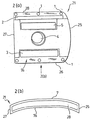
図3から図5には、椎骨10A、10A’の小間節面10、10’および面関節8を有する椎骨区域100の斜視図が示され、椎骨区域100は椎骨の区域を作り上げる。上述説明のように当分野の技術者には理解されるように、小間節面は椎骨の後部構造体であり、この椎骨は、脊椎の髄柱の中で運動を可能にする面関節を形成するために隣接した椎骨の小間節面とつながることができる。各椎骨は、2個の(右および左)上位小間節面および2個の下位小間節面を有する。椎骨10A、10A’の外側塊9、9’もまたそれぞれ示されている。用語「外側塊」は、脊椎の頚部などの、面関節および間にある骨ならびに骨と椎骨の動脈が通って走るトンネルから構成される脊椎の環の外側延長部を参照することが当分野の技術者には概ね理解されよう。
FIGS. 3 to 5 show perspective views of a
図3から図5にはまた、本発明による外側塊ステープル組立体20の実施形態が与えられている。外側塊ステープル組立体20は、2個の面関節ステープルすなわち上位または頭方の端部ステープル21および下位または尾方の端部ステープル21’で構成される。用語「上位または頭方の」および「下位または尾方の」は、埋め込まれたときのステープルの垂直配置を参照することが理解されよう。本明細書に含まれる図に示す実施形態で示すように、これらステープルはアンカープレートを備えることができ、これらアンカープレートは、4Aなどの締付具によって上位椎骨10Aおよび下位椎骨10A’にそれぞれ取り付けられる。概して、締付具4Aは、外側塊の骨材料と係合するための固定手段を有する。一実施形態では、これら締付具が図3から図5で示すように固定手段として役立つねじ部分を有する。本明細書に含まれる図では、1個のステープルが椎骨の各面に固定される一実施形態が示されている。しかしながら、必要に応じてどのような数のステープルも用いられることができることが、当分野の技術者には特に以下の説明に基づいて理解されよう。したがって、例えば2個以上の面関節ステープルが、外側塊の中に面ごとに配置されることができる。
3 to 5 also provide an embodiment of an outer
本発明のステープル(すなわちアンカープレート)が、適した外科グレードの金属または金属合金、あるいは当分野の技術者に知られる他のこの種の耐久性のある材料から作製されることができる。 The staples (ie, anchor plates) of the present invention can be made from a suitable surgical grade metal or metal alloy, or other such durable material known to those skilled in the art.
好ましい実施形態では、これら面関節ステープルが左および右のバージョンで設けられ、これらは椎骨の左および右外側の態様に対応することがまた理解されよう。図1で示す実施形態で示すように、各面関節ステープルは外側面を有し、この外側面は、容易な方向付けを可能にする湾曲形状25を有することができる。図3から図5は、異なるステープルの構成が示される図1の代替実施形態を示す。外側面を持った形状25(図1および図2の中の図の右側)は、外側塊9、9’の外側面に当接し、概して外側塊の概ねの形状に適合するよう成形されている。これは、関節と適合するための湾曲を有する軸プレートのアプリケーションに特に適する。この反対側、すなわち内側部27(図1および図2の図の左側)は、板11、11’に当接する概ね一直線の部分を有する。
It will also be appreciated that in a preferred embodiment, these facet staples are provided in left and right versions, which correspond to the left and right lateral aspects of the vertebra. As shown in the embodiment shown in FIG. 1, each facet joint staple has an outer surface, which can have a
図4および図5に示すように、本発明は、面関節ステープル21、21’に固定される合成の靭帯13を備える。上述のように、合成の靭帯13は、当分野の技術者には理解されるように様々な材料から作製されることができる。
As shown in FIGS. 4 and 5, the present invention comprises a
図1および図2は、本発明の面関節ステープルの一実施形態の追加の図を示す。本発明の面関節ステープルは、相異なったアプリケーションでの使用を可能にするために様々な形状および大きさで製造されることができる。当分野の技術者には、面関節ステープルが相異なった大きさの患者および他の椎骨区域での使用を可能にするために様々な高さおよび幅を含むことが理解されよう。面関節ステープルの高さおよび幅に対する考慮が、(1)患者の大きさ、(2)脊椎の領域、すなわち頚椎、胸椎または腰椎、および(3)アプリケーション、例えば外側塊または棘突起に関してなされることができる。好ましい実施形態では、本発明のインプラントが約2から3mmの厚さであってもよい。この厚さを有する面関節ステープルは靭帯の面関節への取付けが好ましい。 1 and 2 show additional views of one embodiment of the facet joint staple of the present invention. The facet joint staples of the present invention can be manufactured in a variety of shapes and sizes to enable use in different applications. Those skilled in the art will appreciate that facet joint staples include various heights and widths to allow use with different sized patients and other vertebral areas. Considerations for the height and width of the facet staples should be made with respect to (1) patient size, (2) spinal region, ie cervical, thoracic or lumbar, and (3) applications such as lateral mass or spinous processes Can do. In a preferred embodiment, the implant of the present invention may be about 2 to 3 mm thick. The facet joint staple having this thickness is preferably attached to the facet joint of the ligament.
面関節ステープル21、21’は、第1の面7、7’をそれぞれ有し、これら第1の面7、7’は、適用された位置に外面を有する。これらステープルはまた、適用された位置、すなわち外側塊または他の脊椎構造体と接触する面に内面を有する第2の反対側の面を有する。さらに、これらステープルは、第1の縁部28、第2の縁部25、第3の縁部26および第4の縁部27をそれぞれ有する。図1および図2で示す本発明の実施形態では、第1の概ね長手方向の開口3が、縁部26に隣接して各ステープルに対して設けられ、側部25および側部27から延びる長手方向の軸にわたって概ね延びる。長手方向の開口3はまた、外面と内面の間の開口部を画成する。開口3は、図3から図5で理解できるように、以下でさらに説明するように靭帯13の一部を受けるようになされている。第2の長手方向の開口5がまた、各ステープルに設けられている。第2の開口5はまた、外面と内面の間に延びる開口部を画成し、縁部28と隣接して設けられる。第2の開口5は、第1の開口3と構成が同様であり、靭帯13の一部を受けるようになされている。
The facet
各ステープルは、面関節ステープルを通って延びる締付具受入開口4をさらに備える。図1および図2に示す本発明の実施形態では、締付具受入開口4は、面関節ステープル21の概ね中央に設けられている。本発明の代替実施形態では、図6(a)、図6(b)および図6(c)で理解できるように、締付具受入開口4は、面関節ステープル21の周りの相異なった位置にあることができる。締付具受入開口4は、椎骨10Aまたは10A’に面関節ステープル21を付ける締付具を受けるようになされている。図2bに示すように、この面関節ステープルは、面関節ステープルが取り付けられるべき椎骨の面と概ね適合するように内側から外側への湾曲を有することができる。
Each staple further comprises a
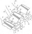
図に示すように、ステープル21は開口3および開口5を備え、一方、ステープル21は同等の開口3’および開口5’を備える。長手方向の開口3、開口3’、開口5および開口5’は、靭帯13がその中を通ることを可能にするために概ね平坦な面を備える。好ましい実施例では、靭帯13は、示すように開口3、開口5、開口3’および開口5’のそれぞれを通ってそれぞれ装着される。面関節ステープル21、21’が椎骨10、10A’に配置されるか付けられるときに外側塊ステープル組立体20を配置するために、靭帯13は、本明細書で説明するように関節に必要な安定性をもたらすためにそれら長手方向の開口の中を通されることができる。
As shown, the
図4および図5に示した実施形態に示すように、本発明の装置を埋め込む際、合成の靭帯13は、開口3、開口5、開口3’および開口5’をそれぞれ通って後部から下位に通される。示すように、この方法では、この靭帯は、脊椎の骨組織とそれぞれステープル21、21’の内側の面7、7’の間に横たわるように方向付けられる。理解できるように、この種の方向付けでは、ステープルを固定するために用いられる締付具4A、4A’は、合成の靭帯13を通って延びる。次いで、ステープル21、21’は、靭帯13を通って締付具4Aによって付けられることができる。
As shown in the embodiment shown in FIGS. 4 and 5, when implanting the device of the present invention, the
図4および図5は、合成の靭帯13の右の面関節への取付けのために用いる際の本発明の実施形態を示す。2個のステープル21、21’が示され、1個がこの面関節の各側に配置され、各ステープルは締付具4A、4A’によってそれぞれの外側塊に取り付けられる。
4 and 5 show an embodiment of the present invention when used for attaching a
図4は伸長時の右の面関節を示し、一方、図5は屈曲時の右の面関節を示す。当分野の技術者には理解されるように、用語「伸長」は、脊椎の前部から後部への運動(すなわち後方向きの曲げ)であり、一方、用語「屈曲」は脊椎の後部から前部への運動(すなわち前方向きの曲げ)である。図5で理解できるように、本発明の装置が埋め込まれている脊椎が屈曲していると、合成の靭帯13は生体内の面関節被膜と同種の方法で屈曲の程度を制限する働きをする。脊椎区域が伸長すると、本発明の外側塊ステープル組立体は運動の範囲を制限せずに、この制限は伸長への自然な制限の結果により、すなわちこれら面関節が互いに当接する。図4で理解できるように、伸長の間、合成の靭帯13は曲がることができ、この組み入れられた弛緩により、次の屈曲時に面関節の通常の運動が可能になる。
FIG. 4 shows the right face joint when extended, while FIG. 5 shows the right face joint when bent. As will be appreciated by those skilled in the art, the term “extension” is an anterior to posterior movement of the spine (ie, posterior bending), while the term “flexion” is the anterior to posterior of the spine. Movement to the part (ie bending forward). As can be seen in FIG. 5, when the spine in which the device of the present invention is implanted is bent, the
図5で理解できるように、合成の靭帯13は、屈曲時に面関節8をわたって緊張して伸ばされ、それによって関節を抑制する。したがって、外側塊ステープル組立体20は、屈曲時に面関節の安定性を可能にする。当分野の技術者には理解されるように、本明細書で説明する安定化インプラントは、首の屈曲を制限するための脊椎の頚部区域の中への埋込みに特に適している。特に、本明細書で開示する装置により、頚椎の中で面関節被膜によってもたらされる通常の屈曲の制限の再生が可能になる。
As can be seen in FIG. 5, the
最後に、外側塊ステープル組立体20の場合の回転運動(図示せず)は、下に横たわる面関節および反対側の面関節の構成によってある程度制限されることになる。しかしながら、靭帯13の特性が、被膜および小間節面脱臼によって制限される不全脱臼の地点までの過度の回転などの過度の回転を制限する。
Finally, the rotational motion (not shown) for the outer
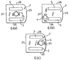
好ましい実施形態では、締付具受入開口4は、ねじおよびより詳しくは当技術分野で一般に知られる外側塊ねじなどの締付具を受けるためにねじ山をつけられることができる。本発明の面関節ステープルに関連して用いられることができる締付具の例には、ねじ、スパイク、ピン、ロッド、タイまたは縫合糸が含まれる。これら締付具は、関節間部、外側塊、茎、棘突起、または骨棘の中の全ての他の要素の中に挿入されることができる。この締付具はまた、上述の人工の同等物の中に挿入されることができる。しかしながら、本発明がこれら締付具とともに用いることに制限されないことが理解されよう。例えば、代替実施形態では、この締付具が、ナットと固定されたボルトであることがある。好ましくは締付具受入開口4は、図1および図2ならびに図6(a)、図6(b)、図6(c)で示すように、締付具の隣接した骨の中への角度のある挿入を可能にし、骨のてこ装置を最大化させ、締付具が他の組織を損傷する可能性を最小化させるために角度が付けられている。この角度は、脊椎の様々な領域で下に横たわる骨の量および配置ならびにこの骨を動かす力のある周りの構造体の関係によって決まる。この角度により、標準の外側塊ねじが用いられることが可能になる。ステープルのプレート部分の厚さ(概ね約2mm以上である)に応じて、一直線の穴を通る角度に適しまたは満足する軌跡を獲得することが、外科医にとって問題である場合があった。締付具受入開口4の角度は、この問題を克服する助けとなり、一方、面関節ステープルの厚さの変化を可能にする。好ましい実施形態では、締付具受入開口4は、外側の面(7、7’)から内側面に外側に(25に向かって)20から40°の間の角度および上位に(すなわち縁部28に向かって)0から20°の角度が付けられることができる。さらに好ましくは、頚部の外側塊および小間節面のアプリケーションでは、締付具受入開口4の角度は、外側塊かそれとも茎の固定を可能にするために両方向(「上向きおよび外向き」と呼ばれる上方および下方へならびに内側および外側)に25°であることができる。この締付具受入開口の角度および位置は、茎または標準のねじを含めて様々なタイプの締付具に適応するために変えられることができる。
In a preferred embodiment, the
この締付具受入開口の直径は、用いられる締付具の直径に応じて変えられることができる。締付具4Aはまた、隣接した骨構造体に面関節ステープルを取り付けるかまたは付けるとき、靭帯13を付けるために靭帯13の中を通ることができる。したがって、締付具4Aの挿入により、靭帯の周りの骨材料の成長を助長することができる。
The diameter of the fastener receiving opening can be varied depending on the diameter of the fastener used. The
別の実施形態では、ステープルの外側の面7、7’は、定位置で締付具受入開口4の中に挿入される締付具4Aを保持するための締付具錠を備えることができる。好ましい実施形態では、図1(b)に示すように、この錠は、締付具4Aの運動を停止させ、それが締付具受入開口4からはずれることを防止することができる少なくとも1個の回転可能なフランジ15で構成される。回転可能なフランジ15は、締付具受入開口4に隣接して第1の面7、7’の上に設けられる。締付具4Aが骨に脊椎インプラントを付けるために用いられると、締付具4Aの頭部は、第1の面の上にわずかに突出する。次いで、フランジ15は、締付具4Aの頭部の上を回転させられ、締付具4Aを定位置で施錠し、これにより骨から自由に動くことを防止することができる。図1で、より詳細には図7で示すように、フランジ15、15’を施錠すると、締付具受入開口4からの締付具4Aの出入りを可能にする第1の位置から、締付具受入開口4から締付具4Aが出て行くことを停止することができる第2の位置に移動されることができる。締付具4Aが締付具受入開口4の中に挿入されると、フランジ15、15’を施錠させることにより、締付具4Aを定位置に施錠するために第1の位置から第2の位置に移動されることができる。この形の締付具および錠は好ましいが、本発明は、この締付具および錠に限定はされない。このインプラントが付けられる骨から締付具が自由に動くことを防止する助けとなる様々な代替の締付具および錠が、少なくとも1個のフランジと置換されることができる。
In another embodiment, the
図6a、図6bおよび図6cは、本発明の外側塊ステープルの締付具受入開口4の位置が変えられた様々な実施形態を示す。好ましい実施形態では、締付具受入開口の配置が、このインプラントが用いられる脊椎の領域に基づく。図6aでは、締付具受入開口が、概して面関節ステープルの中央に設けられる。この実施形態は、靭帯の頚椎の外側塊への取付けのために特に役立つ。この実施形態では、締付具受入開口が、外側塊の中央に対して上向きで外向き25°の角度が付けられていることが好ましい。図6bは、面関節ステープルの代替実施形態を示し、この実施形態では、締付具受入開口は、開口3など第1の長手方向の下位開口の一端部ならびに隣接した縁部Cおよび縁部Dに隣接して設けられる。図6bで示す締付具受入開口24の配置は、より内側に配置された穴を通って配置できるC2部またはC2茎ねじでの靭帯のC2椎骨の板への取付けに特に役立つ。この茎ねじの配置はまた、示すようにより外側のねじ穴を通って容易にされる。この実施形態では、締付具受入開口4が上方に45°の角度が付けられていることが好ましい。
Figures 6a, 6b and 6c show various embodiments in which the position of the
図6cは、面関節ステープルの、締付具受入開口4が湾曲形状の縁部Bに隣接し、第1の開口3と第2の開口5の間に設けられる代替実施形態を示す。この実施形態は、靭帯のC7椎骨または胸茎への取付けに特に役立つ。この実施形態では、締付具受入開口は、より大きなねじ、例えば茎ねじを受け入れるような大きさである。この締付具受入開口は、下方に10°(26に向いて7から7’に)および内側に0から45°(27に向いて7から7’に)の角度がある。
FIG. 6 c shows an alternative embodiment of the facet joint staple where the
図2に示すように、塊ステープル21または21’の各内側の面7a、7a’はまた、それぞれ少なくとも1個の安定化部材1を有することができる。図2に示すように、一実施形態では、6個以上の安定化部材が設けられる。安定化部材1は、隣接した骨構造体を貫通することができ、したがって面関節ステープルの隣接した骨構造体への固定を可能にする。安定化部材の実施例には、歯、ピンおよびスパイクが含まれるが限定はされない。この少なくとも1個の安定化部材は、隣接した構造体にインプラントを取り付ける助けとなるだけでなく、靭帯材料または靭帯13の中を通り、靭帯を介して骨成長を可能にする。より最近の塊ステープル21、21’の内側(すなわち骨が接触する)の面7、7’のそれぞれは、外側塊ステープル組立体20の外側塊への持続的な固定を助長する骨成長を可能にするために粗面化された面、多孔性の表面処理または皮膜加工を有することが好ましい。一実施形態では、第1の長手方向の開口3および第2の長手方向の開口5の間の内側の面7a、7a’の区域は、この区域で骨成長の増進することを可能にするために粗くされることができる。別の実施形態では、内側の面7a、7a’が、チタニウム粒子噴霧またはプラズマポア(plasmapor)など多孔性の物質で被覆加工されることができる。別の実施形態では、内側の面7a、7a’が、当分野の技術者に知られる中空のケージまたは同様のメッシュタイプの構造体を有し、この構造体の中には,このケージの中に骨成長を促進する骨形態形成タンパク質(例えばrhBMP2またはrhBMP−7)など骨成長物質が配置され、したがって、面関節ステープルの中に骨を組み込むことができる。様々な他の同様の処理および被覆加工はまた、当分野の技術者には明らかな特徴を備えることができる。
As shown in FIG. 2, each
図1および図2に示すように、内側の面7a、7a’はまた、1個または複数個のリザバー2を有することができる。リザバー2は、骨成長を助長するために骨成長を促進するタンパク質など骨の癒着促進材料を有することができる。本発明の実施形態では、リザバー2は、面関節から最も離れた面に沿った面7’の中の概ねU字形の陥凹である。つまり、上位面関節ステープル21は、上位端部に近い開口5に隣接したリザバー2を有するが、下位関節ステープル21’に対しては、リザバーは、構造体の下位端部に近い開口5’に隣接して配置されることになる。次いで、3個以上の面関節ステープルが用いられるべき場合には、中間ステープルまたはステープルが開口3および開口5の両方に隣接してリザバーを有することができることが理解されよう。図3の構成は、2個の当接する小間節面ステープルのただの実施例である。
As shown in FIGS. 1 and 2, the
棘突起に取り付けるためのステープルが設けられている本発明の実施形態が図8aから図8eに示されている。図8(e)に示す棘突起ステープル110は、上述と同じ方法で合成の靭帯(図示せず)の図8(d)の棘突起150への取付けを可能にするようになされている。図8(a)から図8(e)に示すステープル110は、棘間および棘上の靭帯の靭帯再生のため、ならびに脊椎の屈曲を制限するために用いられることができる。ステープル110は、椎骨120の棘突起150をまたぐようになされている。概して、U字形のステープル110は、第1のアーム111および第2のアーム112をそれぞれ有する。図8(e)に示すように、第1および第2のアームは、U字形ステープル110の1つのアームの上に外面114、115、ならびに第1の面114および第2の面115の反対側に内面116、116’を有する。
An embodiment of the invention in which staples are provided for attachment to the spinous process is shown in FIGS. 8a to 8e. The
外面およびこれに対応する内面のそれぞれは、靭帯がそこを通ることを可能にするための各アームの本体を通って延びる少なくとも2個の開口(122、123、124、125)を有する。さらに、外面およびこれに対応する内面のそれぞれは、締付具がそこを通って隣接した棘突起の中を通ることを可能にするための締付具受入開口(130、132)を有する。 Each of the outer surface and the corresponding inner surface has at least two openings (122, 123, 124, 125) that extend through the body of each arm to allow the ligaments to pass therethrough. In addition, each of the outer surface and the corresponding inner surface has a fastener receiving opening (130, 132) for allowing the fastener to pass through the adjacent spinous process.
外面の少なくとも1つは、さらに前で説明したように機能する締付具錠を有する。図8(a)から図8(e)で示す実施形態では、第1の外面114に含まれる締付具錠は、1対のフランジ140で構成される。
At least one of the outer surfaces has a fastener lock that functions as further described above. In the embodiment shown in FIGS. 8A to 8E, the fastener lock included in the first
インプラント110の第1および第2の内面は、安定化部材、骨の癒着促進材料を含むためのリザバー、および骨の成長を促進する複数の微細孔を含む上述のステープル10の第2の面7’の全ての特徴を有することができる。
The first and second inner surfaces of the
上述の説明から、本発明の様々な独特の特徴が究明されることができる。まず、本明細書で説明した脊椎安定化インプラントは、効率的な面関節被膜、特に頚椎のための再生を備える。棘突起上で用いられる上述の実施形態により、棘間および棘上の靭帯再生、および脊椎の中の屈曲の動的制限がまた可能になることがまた理解されよう。 From the above description, various unique features of the present invention can be determined. First, the spinal stabilization implant described herein comprises an efficient facet joint capsule, particularly regeneration for the cervical spine. It will also be appreciated that the above-described embodiments used on the spinous process also allow for ligament regeneration between and above the spines and dynamic restriction of flexion in the spine.
本装置の独自の特徴の1つは、本装置が合成の靭帯の外側塊への急速で持続性のある固定をもたらすことである。これは、主としてステープルの構造的特徴によって実現される。例えば、ステープルの多孔性面構造体は骨成長をステープルの中に促進させる。さらに、安定化部材(例えば、ピン)は、外側塊の骨領域を捕捉し、さらに合成の靭帯の中を通る場合はそこを通って骨成長を促進する。骨の癒着促進材料のリザバー2はまた、合成の靭帯を通って骨成長を促進する。
One of the unique features of the device is that it provides rapid and persistent fixation to the outer mass of the synthetic ligament. This is achieved mainly by the structural features of the staples. For example, the porous surface structure of the staple promotes bone growth into the staple. In addition, the stabilizing member (eg, pin) captures the bone region of the outer mass and promotes bone growth therethrough when passing through the synthetic ligament. The bone adhesion promoting
本発明の別の特徴は、例えば外側塊上への配置を容易にするステープル下面の内側から外側の形状を含む。 Another feature of the present invention includes an inside-to-outside shape of the underside of the staple that facilitates placement on the outer mass, for example.
様々な方法が合成の靭帯にステープルを固定するために用いられることができることが当分野の技術者には理解されよう。上述のように、一実施形態では、合成の靭帯は、固定締付具(例えば、外側塊ねじなどのねじ)および安定化部材(例えば、安定化ピン)の両方によって定位置に保持される。代替的には、合成の靭帯は、クリップ、ねじ、またはさもなければその他の全ての方法でそれぞれのステープルに固定され、一方で同じ目的を実現することができる。 Those skilled in the art will appreciate that various methods can be used to secure the staples to the synthetic ligament. As described above, in one embodiment, the synthetic ligament is held in place by both a fixation fastener (eg, a screw such as an outer mass screw) and a stabilization member (eg, a stabilization pin). Alternatively, the synthetic ligament can be secured to the respective staples by clips, screws, or otherwise in all other ways, while achieving the same purpose.
図1から図8で示す上述説明では、本発明の実施形態が、設けられた2個のステープルに関して示された。しかしながら、理解されるように、本方法で脊椎を安定化させる過程では、所望の安定性を実現するためにいくつかの椎骨に本装置を適用することが必要なことがある。この方法では、合成の靭帯が、その長さに沿って各ステープルに固定された状態で各側が連続的であることができる。代替的には、合成の靭帯が、統合された靭帯を効率的に実現するために各部分が連続して固定された状態で様々な部分で形成されることができる。本発明に用いられる合成の靭帯が具体的な必要性に基づいた長さおよび弾性性能に対して選択されることもまた理解されよう。 In the above description shown in FIGS. 1 to 8, embodiments of the present invention have been shown with respect to two provided staples. However, as will be appreciated, the process of stabilizing the spine with this method may require that the device be applied to several vertebrae to achieve the desired stability. In this way, each side can be continuous with the synthetic ligament secured to each staple along its length. Alternatively, a synthetic ligament can be formed of various parts with each part secured in series to efficiently achieve an integrated ligament. It will also be appreciated that the synthetic ligaments used in the present invention are selected for length and elastic performance based on specific needs.
上述の説明のように、ステープルの締付具受入開口は、例えば、外側塊ねじの配置を可能にするために角度が付けられることが好ましい。さらに、この角度は、C2椎骨部および茎部の中へのねじなど相異なったねじの軌跡を受け入れるために必要に応じ変えられることができる。様々な他の角度および方向付けが、ステープルが中に固定されるべき所望の骨構造体に応じて当分野の技術者には明白であろう。例えば、本発明のステープルは、人工の板、茎、外側塊、または椎骨、あるいはそれらの全ての組合せに固定されることができる。 As described above, the staple fastener receiving opening is preferably angled, for example, to allow placement of the outer mass screw. In addition, this angle can be varied as needed to accommodate different screw trajectories, such as screws into the C2 vertebra and stem. Various other angles and orientations will be apparent to those skilled in the art depending on the desired bone structure in which the staples are to be secured. For example, the staples of the present invention can be secured to an artificial plate, stem, outer mass, or vertebra, or any combination thereof.
当分野の技術者には理解されるように、これらステープルの一実施形態の一直線の内側縁部は、椎板切除術など可能な減圧処置を妨害しない。上述のように、この一直線の縁部は、減圧部をまたぐことができる。 As will be appreciated by those skilled in the art, the straight inner edge of one embodiment of these staples does not interfere with possible decompression procedures such as discectomy. As described above, this straight edge can straddle the decompression section.
本明細書で説明される本装置の別の独特の特徴は、合成の靭帯のステープルおよび関連した骨構造体(すなわち、外側塊)への即時の固定を実現する「ベルトバックル」方法の使用である。この方法は、適した弾力性のある靭帯材料の選択とともに、通常の面関節被膜と同様の特定の量の弾力性を可能にする。この独特の取付け手段はまた、これの目立たない存在(すなわち、外側塊上に直接配置されていること)により、回転運動時に小間節面を安定化させる。 Another unique feature of the device described herein is the use of a “belt buckle” method that provides immediate fixation to a synthetic ligament staple and associated bone structure (ie, outer mass). is there. This method, together with the selection of a suitable elastic ligament material, allows a specific amount of elasticity similar to a normal facet joint capsule. This unique attachment means also stabilizes the booth surface during rotational movement due to its inconspicuous presence (i.e., located directly on the outer mass).
本発明の別の実施形態を図10から図11に示す。これらの図では、安定化インプラントは、このインプラントが外側塊などの椎骨の他の骨構造体に取り付けられた状態で椎骨用の人工の棘突起および板を備える。この実施形態では、インプラント300は、自然に生じる棘突起、および場合によっては板が脊髄および脊髄硬膜を露出させるために切除される場合に脊椎の領域にわたって配置されるようになされている。当分野の技術者には知られるように、この種の処置は減圧椎弓切除術を含むことができる。インプラント300は、外側塊その他などの椎骨の様々な部分に取り付けられることができる。代替的には、インプラント300は、上述説明のステープルなど他のステープル(および前図で品目21、21’と呼ばれる)、または人工面関節その他などの同様の補綴に取り付けられることができる。
Another embodiment of the present invention is shown in FIGS. In these figures, the stabilizing implant comprises an artificial spinous process and plate for the vertebra with the implant attached to other bone structures of the vertebra such as the outer mass. In this embodiment, the
図10aおよび図10bに示すように、インプラント300は、2個の外側に延び隔置されたステープル302、304を備え、これらステープルは、一実施形態では外側塊ステープルを備える。すなわち、ステープル302、304は椎骨上の2個の外側塊に付けられるようになされている。ステープル302、304は、所望の骨構造体に取り付けられるようなされたアンカープレートを有する。ステープル302、304が上述のように様々な骨成長促進手段を有することができることが理解されよう。さらに、ステープル302、304は、開口をもたらす締付具受入開口を有し、この開口を通ってねじ(すなわち、外側塊ねじ)、ピンなどの固定手段が下に横たわる骨構造体と係合するために中を通されることができる。示すように、2個のステープル302、304は、概ね平坦なプレートで、それぞれが同一平面上に横たわる。この方向付けの説明が決して限定を意味するものではないことが理解されよう。すなわち、多くの場合、ステープル302、304は正確には同一平面上にない場合があり、実際には脊椎区域の形状に適合させるために互いに対してわずかに角度が付けられる。
As shown in FIGS. 10a and 10b, the
一実施形態によると、ステープル302、304のそれぞれからは、ステープルの他方に向かって延びるスペーサアーム306、308がそれぞれ延び、アームのそれぞれが互いに延び接合部310で交わるようになる。接合部310は、可動の蝶番を有することができる。代替的には、接合部310は、アーム306、308間の固定された接合であってもよい。図10bに示すように、このスペーサアームは、プレートを有することができる。一実施形態では、スペーサアーム306、308は、接合部310が先端を有するようにステープル302、304が横たわる平面から離れて延びる。スペーサアーム306、308は、それぞれのステープルに固定して連結されることができ、または可動の蝶番312、314とそれぞれ連結されることができる。図10a、図10bで理解できるように、インプラント300は「翼」状の構造体をとる。別の実施形態では、ステープル自体は細長い構造体であってよく、それによって上述のスペーサの必要性をなくすことができる。
According to one embodiment, from each of the
このインプラントは、ステープル302、304が横たわる平面から概ね垂直に延びるフィン316をさらに有する。フィン316は、接合部310および反対側の第2の端部320に連結された第1の端部318を有し、好ましくは肥厚部分を有する。この種の肥厚または球状の構造体は、瘢痕組織または人工靭帯などの取付けを容易にする表面区域を増加させる。この種の構造体は、望まれない屈曲または脊柱後弯症を防止する助けとなる「てこ用アーム」を形成することによってインプラント300に生体力学的な利点を与える。
The implant further includes
第1の端部318は、蝶着または固定して接合部310に連結することができる。一実施形態では、フィン316は、スペーサアーム306またはスペーサアーム308の一方の延長部を含むことができる。スペーサアーム306、308およびフィン316が1個の構造体を有することができることがまた理解されよう。当分野の技術者には理解されるように、この種の単一の構造体は、それぞれの部品間のどのような運動も不能にすることができる。別の実施形態では、2個のスペーサアーム306、308だけが、フィン316およびステープル302、304が独立した構造体の状態で、単独の構造体を有する。別の実施形態では、ステープル、スペーサアームおよびフィンの組合せが、単独の構造体を有することができる。
The
図10および図11では、インプラント300のステープル302、304が、おおよそ同じサイズで示される。しかしながら、各ステープルのサイズは必要に応じて変えられることができる。例えば、より大きな間隔の硬膜鞘が椎骨の一方の側で必要とされるとき、ならびにより広くおよび/またはより長いステープルがその一方の側で必要とされるときなどのいくつかの場合である。
10 and 11, the
これらフィンは上位縁部311および下位縁部313を有し、これら縁部はインプラントが直立脊椎に配置されるとそれらの上位/下位位置にある。示すように、一実施形態では、下位縁部313は概ね一直線で、一方、上位縁部311はこの下位縁部に向かって湾曲を有する。したがって、埋め込まれるとフィン316の前部端部は後部端部より広い。上位縁部311は「後退」形状をさらに有する。
The fins have an
当分野の技術者には理解され、図11aから図11cを参照して説明されたように、フィン316用のこの種の構造体(すなわち一直線の下位縁部313および「後退」上位縁部311の組合せ)は、脊椎の伸長運動(すなわち吻側への運動または尾方への運動)への障害を最小化するかまたは回避し、障害なしに生じるようにする。すなわち、フィン316の先細り形状は、脊椎の運動の間、特に伸長運動の間に隣接したフィンまたは自然の骨構造体との衝突を防止する。この特徴は、図11aから図11cに示される。図11bは、自然の状態でのいくつかのインプラント300を有する脊椎を示す。図11cでは、脊椎は、屈曲(すなわち吻側への)運動にさらされている。図11aは、伸長(すなわち、尾方への)運動で脊椎を含めてインプラントを示す。理解できるように、どちらの場合でも、フィン316の構成は、隣接したインプラント300間、またはインプラント300と隣接した脊椎構造体の間の接触を防止する。
As understood by those skilled in the art and described with reference to FIGS. 11a to 11c, this type of structure for fins 316 (ie, a straight
フィン316は、1個または複数個のスロット319または好ましくはその長さに沿って概ね長手方向に延びる他のこの種の開口部を備える。このスロットまたは開口部は、本発明の前の実施形態を参照した上述の開口3、5の機能と同様である。一実施形態では、少なくとも2個のこの種のスロットが、本開示を考慮すれば当分野の技術者には明白である理由のために設けられる。しかしながら、以下でさらに説明するように、どのような数のスロットもまた設けられることができることもまた明白であろう。
The
図11aから図11cは、脊椎の中に埋め込まれたときのインプラント300を示す。これらインプラントは、例えば椎骨の外側塊に固定される。図11aから図11cの図では、4個のこの種のインプラントが示され、直立の脊椎と垂直に方向付けられている。示すようにこれらインプラントは、インプラントの各フィン316に連結された複数の合成の靭帯322を備える。これら合成の靭帯は、上述の合成の靭帯の場合と同様に全ての適する材料から作製されることができる。
Figures 11a to 11c show the
図11aから図11cに示すように、複数の合成の靭帯322は、それぞれが垂直に隣接したインプラント300を互いに連結する末端側端部を備える。例えば、図11で示す実施形態では、フィン316は、互いに垂直に分離された2個のスロット319を備える。これらスロットは、靭帯322の一方の端部を受け保持するようなされている。したがって、示すように、靭帯322は、上位インプラント300の下位スロットから下方に隣接したインプラントの上位スロットに延びる。このように、各インプラント300は、これに隣接したインプラントに連結される。隣接したインプラントが存在しない場合では(最上位または最下位のインプラントの場合など)、追加の合成の靭帯が設けられることができ(必要な場合)、そこでこの追加の靭帯は末端側端部(インプラントの反対側)で自然に存在する支持靭帯に固定される。代替的には、この種の末端側端部は、上述(図1から図8の品目21、21’参照)のように外側塊ステープルに取り付けられることができる。
As shown in FIGS. 11 a to 11 c, the plurality of
合成の靭帯322の端部は、全ての容認可能な方法によってフィン316に取り付けられることができる。例えば、一態様では、この靭帯はフィン316に縫合されることができる。別の態様では、この翼が、それらの間に歯付きまたはピン構造体を有する2個の分離した半部で形成されることができ、この構造体は、このフィンの半部がともに固定されると合成の靭帯1個または複数個の端部と係合する働きをする。一態様では、これらフィンが、これら半部をともに密閉するために、および/または合成の靭帯をそこにさらに固定するためにその中で骨成長を可能にするようなされている。
The end of the
上述の説明では、合成の靭帯322は、それぞれが隣接したインプラント300に引き続いて取り付けられる複数の部分よって実現されるものと説明された。しかしながら、同じ効果が各フィン316に取り付けられた連続的な靭帯などの連続的な合成の靭帯によって実現されることができることが理解できよう。この連続的な靭帯の端末側端部は、上述のように既存の脊椎要素に固定されることができる。
In the above description, the
上述のようにフィンで骨成長を促進することに加えて、インプラント300の様々な他の部分(または構造体全体)は、様々な被覆加工、表面処理、および骨成長を促進するための構造的または化学的因子を含むリザバーなどを備えることができることが理解されよう。この種の因子の様々な実施例は以前に説明された。例えば、インプラントの様々な部分は、骨、筋肉、筋膜、瘢痕組織などのための位置を固定させるためにくぼみのある表面を備えることができる。この種の表面にはまた、同じ目的を実現するために複数の穴を開けることができる。同様に、このインプラントのいくつかまたは全ての表面が、骨または他の組織(すなわち、瘢痕組織、筋肉など)の成長を促進するための物理的および/または化学的なエンハンサーで被覆加工することができる。 In addition to promoting bone growth with fins as described above, various other parts of implant 300 (or the entire structure) can be applied to various coating processes, surface treatments, and structural to promote bone growth. It will also be appreciated that a reservoir or the like containing chemical factors can be provided. Various examples of this type of factor have been described previously. For example, various portions of the implant can include recessed surfaces to fix positions for bone, muscle, fascia, scar tissue, and the like. This type of surface can also be perforated to achieve the same purpose. Similarly, some or all of the surface of the implant may be coated with a physical and / or chemical enhancer to promote the growth of bone or other tissue (ie, scar tissue, muscle, etc.). it can.
インプラント300間の運動の範囲が合成の靭帯の長さおよび弾力性によって決まることが理解されよう。これは図11aを図11cに比較して気づかれる。したがって、(特に)インプラント300によって与えられる屈曲の程度が合成の靭帯用に適した長さおよび材料のタイプを選択することによって必要に応じて調整できることが当分野の技術者には理解されよう。別の態様では、インプラント300の合成の靭帯322は、インプラント300間および/または隣接した椎骨との間の運動の範囲を制限するために1個または複数個の「ストッパ」機構を備えることができる。この種の制限は、変性疾患の進行を調節することが望まれるときに示唆される。この種の「ストッパ」は、例えば、フィンの端部320の延長部を含むことができる。そのような場合、これらストッパは、伸長(図11a)の間に伸長運動の範囲を制限するために互いに干渉するように(大きさおよび配置が)なされることができる。
It will be appreciated that the range of motion between the
本発明を特定の具体的な実施形態を参照して説明したが、当分野の技術者には、本明細書で説明された本発明の目的および範囲から逸脱することなくその様々な改変形態が明白であろう。上述の列挙された参照の開示の全ては、本明細書に参照として組み込まれる。 Although the invention has been described with reference to specific specific embodiments, those skilled in the art will recognize that various modifications can be made without departing from the purpose and scope of the invention described herein. It will be obvious. All of the above listed reference disclosures are incorporated herein by reference.
Claims (21)
前記椎骨が1個または複数個の骨構造体を有し、
前記インプラントが、
前記椎骨のうちの第1の椎骨に固定するための第1のアンカープレートと、
前記椎骨のうちの第2の椎骨に固定するための第2のアンカープレートと
を備え、
前記第1および第2のアンカープレートが、前記椎骨の前記骨構造体と係合するために締付具を受けるための1個または複数個の締付具開口を有し、
前記インプラントがさらに、
前記第1および第2のアンカープレートの間に延び、前記アンカープレート間の弾力性のある相対運動を可能にする弾性部材、
を備える脊椎安定化インプラント。 A spinal stabilization implant for attachment to two adjacent vertebrae,
The vertebra has one or more bone structures;
The implant is
A first anchor plate for securing to a first of the vertebrae;
A second anchor plate for securing to a second of the vertebrae,
The first and second anchor plates have one or more fastener openings for receiving fasteners for engaging the bone structure of the vertebra;
The implant further comprises:
An elastic member extending between the first and second anchor plates and enabling a resilient relative movement between the anchor plates;
A spinal stabilization implant comprising:
前記椎骨が1個または複数個の骨構造体を有し、
前記インプラントが、
前記椎骨のうちの第1の椎骨に固定するための1対の第1の隔置されたアンカープレートと、
前記椎骨のうちの第2の椎骨に固定するための1対の第2の隔置されたアンカープレートと
を備え、
前記対のアンカープレートのそれぞれが概ね同一平面上にあり、
前記第1および第2のアンカープレートが前記椎骨の前記骨構造体と係合するために締付具を受けるための1個または複数個の締付具開口を有し、
前記対のアンカープレートのそれぞれが概ね平面のフィンと連結され、前記フィンが前記それぞれの対のアンカープレートを含む平面に概ね垂直であり、前記フィンが第1のアンカープレート連結端部と、反対側に方向付けられた第2の自由端部とを有し、
前記フィンがその間に延びる弾性部材と連結される脊椎安定化インプラント。 A spinal stabilization implant for attachment to two adjacent vertebrae,
The vertebra has one or more bone structures;
The implant is
A pair of first spaced anchor plates for securing to a first of the vertebrae;
A pair of second spaced anchor plates for securing to a second of the vertebrae,
Each of the pair of anchor plates is generally coplanar;
The first and second anchor plates have one or more fastener openings for receiving fasteners for engaging the bone structure of the vertebra;
Each of the pair of anchor plates is coupled to a generally planar fin, the fin being generally perpendicular to a plane including the respective pair of anchor plates, and the fin being opposite the first anchor plate coupling end. A second free end directed to
A spinal stabilization implant in which the fins are connected to an elastic member extending therebetween.
前記椎骨に固定するための第1および第2のアンカープレートと、
前記椎骨に前記アンカープレートを締め付けるための1個または複数個の締結手段と、
前記第1と第2のアンカープレートを連結するための少なくとも1個の弾性部材と
を備えるキット。 A spinal stabilization implant kit for attachment to two adjacent vertebrae, comprising:
First and second anchor plates for fixation to the vertebrae;
One or more fastening means for fastening the anchor plate to the vertebra;
A kit comprising at least one elastic member for connecting the first and second anchor plates.
Applications Claiming Priority (2)
| Application Number | Priority Date | Filing Date | Title |
|---|---|---|---|
| US59473105P | 2005-05-02 | 2005-05-02 | |
| PCT/CA2006/000678 WO2006116853A1 (en) | 2005-05-02 | 2006-05-02 | Spinal stabilisation implant |
Publications (2)
| Publication Number | Publication Date |
|---|---|
| JP2008539831A true JP2008539831A (en) | 2008-11-20 |
| JP2008539831A5 JP2008539831A5 (en) | 2011-06-30 |
Family
ID=37307557
Family Applications (1)
| Application Number | Title | Priority Date | Filing Date |
|---|---|---|---|
| JP2008509279A Pending JP2008539831A (en) | 2005-05-02 | 2006-05-02 | Spinal stabilization implant |
Country Status (11)
| Country | Link |
|---|---|
| US (1) | US20080132954A1 (en) |
| EP (1) | EP1879516A4 (en) |
| JP (1) | JP2008539831A (en) |
| KR (1) | KR20080016586A (en) |
| CN (1) | CN100563591C (en) |
| AU (1) | AU2006243714A1 (en) |
| BR (1) | BRPI0610995A2 (en) |
| CA (1) | CA2607316A1 (en) |
| MX (1) | MX2007012980A (en) |
| RU (1) | RU2430700C2 (en) |
| WO (1) | WO2006116853A1 (en) |
Families Citing this family (39)
| Publication number | Priority date | Publication date | Assignee | Title |
|---|---|---|---|---|
| GB0107708D0 (en) * | 2001-03-28 | 2001-05-16 | Imp College Innovations Ltd | Bone fixated,articulated joint load control device |
| US7806911B2 (en) * | 2006-04-14 | 2010-10-05 | Warsaw Orthopedic, Inc. | Fixation plate and method of use |
| US7988691B2 (en) * | 2007-02-13 | 2011-08-02 | Depuy Products, Inc. | Orthopaedic trauma bone plate kit |
| US7799058B2 (en) | 2007-04-19 | 2010-09-21 | Zimmer Gmbh | Interspinous spacer |
| US9655648B2 (en) | 2007-05-01 | 2017-05-23 | Moximed, Inc. | Femoral and tibial base components |
| US20100137996A1 (en) | 2007-05-01 | 2010-06-03 | Moximed, Inc. | Femoral and tibial base components |
| US8123805B2 (en) | 2007-05-01 | 2012-02-28 | Moximed, Inc. | Adjustable absorber designs for implantable device |
| US8088166B2 (en) * | 2007-05-01 | 2012-01-03 | Moximed, Inc. | Adjustable absorber designs for implantable device |
| US20110245928A1 (en) | 2010-04-06 | 2011-10-06 | Moximed, Inc. | Femoral and Tibial Bases |
| US8709090B2 (en) | 2007-05-01 | 2014-04-29 | Moximed, Inc. | Adjustable absorber designs for implantable device |
| US8894714B2 (en) | 2007-05-01 | 2014-11-25 | Moximed, Inc. | Unlinked implantable knee unloading device |
| US20080275567A1 (en) | 2007-05-01 | 2008-11-06 | Exploramed Nc4, Inc. | Extra-Articular Implantable Mechanical Energy Absorbing Systems |
| US7678147B2 (en) * | 2007-05-01 | 2010-03-16 | Moximed, Inc. | Extra-articular implantable mechanical energy absorbing systems and implantation method |
| US9907645B2 (en) | 2007-05-01 | 2018-03-06 | Moximed, Inc. | Adjustable absorber designs for implantable device |
| US7846211B2 (en) * | 2007-07-09 | 2010-12-07 | Moximed, Inc. | Surgical implantation method and devices for an extra-articular mechanical energy absorbing apparatus |
| US20090018665A1 (en) * | 2007-07-09 | 2009-01-15 | Exploramed Nc4, Inc. | Surgical implantation method and devices for an extra-articular mechanical energy absorbing apparatus |
| US7632310B2 (en) * | 2007-07-09 | 2009-12-15 | Moximed, Inc. | Surgical implantation method and devices for an extra-articular mechanical energy absorbing apparatus |
| US8425616B2 (en) * | 2007-07-09 | 2013-04-23 | Moximed, Inc. | Surgical implantation method and devices for an extra-articular mechanical energy absorbing apparatus |
| US8252029B2 (en) | 2008-02-21 | 2012-08-28 | Zimmer Gmbh | Expandable interspinous process spacer with lateral support and method for implantation |
| WO2009155360A2 (en) | 2008-06-20 | 2009-12-23 | Neil Duggal | Systems and methods for posterior dynamic stabilization |
| US8945184B2 (en) * | 2009-03-13 | 2015-02-03 | Spinal Simplicity Llc. | Interspinous process implant and fusion cage spacer |
| US20100268278A1 (en) * | 2009-04-15 | 2010-10-21 | Warsaw Orthopedic, Inc. | Tension band |
| US9278004B2 (en) | 2009-08-27 | 2016-03-08 | Cotera, Inc. | Method and apparatus for altering biomechanics of the articular joints |
| CN116570353A (en) | 2009-08-27 | 2023-08-11 | 铸造有限责任公司 | Device for changing the load between the patella and the femur in a knee joint and for treating hip joint diseases |
| US10349980B2 (en) | 2009-08-27 | 2019-07-16 | The Foundry, Llc | Method and apparatus for altering biomechanics of the shoulder |
| US9668868B2 (en) | 2009-08-27 | 2017-06-06 | Cotera, Inc. | Apparatus and methods for treatment of patellofemoral conditions |
| US9861408B2 (en) | 2009-08-27 | 2018-01-09 | The Foundry, Llc | Method and apparatus for treating canine cruciate ligament disease |
| EP2481377A4 (en) * | 2009-09-22 | 2017-12-20 | Olympus Corporation | Space-securing device |
| FR2961687B1 (en) * | 2010-06-23 | 2015-05-22 | Cousin Biotech | LONGILINE ELEMENT RETENTION DEVICE SUITABLE FOR MAINTAINING DETERMINED INTERVERTEBRAL CLEARANCE |
| US9044270B2 (en) | 2011-03-29 | 2015-06-02 | Moximed, Inc. | Apparatus for controlling a load on a hip joint |
| EP2910208B1 (en) | 2011-04-01 | 2017-05-17 | Synthes GmbH | Posterior vertebral plating system |
| WO2013182062A1 (en) * | 2012-06-08 | 2013-12-12 | 河北医科大学第三医院 | Bionic elastic fixing device |
| CN102670293A (en) * | 2012-06-08 | 2012-09-19 | 张英泽 | Bionic elastic fixing device |
| US9468466B1 (en) | 2012-08-24 | 2016-10-18 | Cotera, Inc. | Method and apparatus for altering biomechanics of the spine |
| CN105073023A (en) * | 2012-12-20 | 2015-11-18 | 脊柱诊察公司 | Discectomy devices and methods |
| EP3111099B1 (en) | 2014-02-24 | 2020-04-01 | Curtin University Of Technology | A fastener |
| CN108778152B (en) | 2016-03-18 | 2022-05-10 | 科廷大学 | Expandable fasteners for orthopedic applications |
| US10463403B2 (en) * | 2017-07-31 | 2019-11-05 | Medos International Sarl | Systems and methods for reducing the risk of proximal junctional kyphosis using a bone anchor or other attachment point |
| US11389209B2 (en) | 2019-07-19 | 2022-07-19 | Medos International Sarl | Surgical plating systems, devices, and related methods |
Citations (3)
| Publication number | Priority date | Publication date | Assignee | Title |
|---|---|---|---|---|
| US5415661A (en) * | 1993-03-24 | 1995-05-16 | University Of Miami | Implantable spinal assist device |
| US5733284A (en) * | 1993-08-27 | 1998-03-31 | Paulette Fairant | Device for anchoring spinal instrumentation on a vertebra |
| US20050033434A1 (en) * | 2003-08-06 | 2005-02-10 | Sdgi Holdings, Inc. | Posterior elements motion restoring device |
Family Cites Families (11)
| Publication number | Priority date | Publication date | Assignee | Title |
|---|---|---|---|---|
| FR2689750B1 (en) * | 1992-04-10 | 1997-01-31 | Eurosurgical | BONE ANCHORING ELEMENT AND SPINAL OSTEOSYNTHESIS DEVICE INCORPORATING SUCH ELEMENTS. |
| US5352229A (en) * | 1993-05-12 | 1994-10-04 | Marlowe Goble E | Arbor press staple and washer and method for its use |
| JP2003523784A (en) * | 1999-04-05 | 2003-08-12 | サージカル ダイナミックス インコーポレイテッド | Artificial spinal ligament |
| US6296643B1 (en) | 1999-04-23 | 2001-10-02 | Sdgi Holdings, Inc. | Device for the correction of spinal deformities through vertebral body tethering without fusion |
| DK1239785T3 (en) * | 1999-12-20 | 2004-11-29 | Synthes Ag | Device for stabilizing two adjacent vertebral bodies of the vertebral column |
| US6312431B1 (en) * | 2000-04-24 | 2001-11-06 | Wilson T. Asfora | Vertebrae linking system |
| US6419703B1 (en) * | 2001-03-01 | 2002-07-16 | T. Wade Fallin | Prosthesis for the replacement of a posterior element of a vertebra |
| US20030187509A1 (en) | 2002-04-01 | 2003-10-02 | Lemole G. Michael | Modulus plating system and method |
| US6994727B2 (en) * | 2002-12-17 | 2006-02-07 | Amedica Corporation | Total disc implant |
| US7708765B2 (en) * | 2004-08-03 | 2010-05-04 | K Spine, Inc. | Spine stabilization device and method |
| US7837688B2 (en) * | 2005-06-13 | 2010-11-23 | Globus Medical | Spinous process spacer |
-
2006
- 2006-05-02 AU AU2006243714A patent/AU2006243714A1/en not_active Abandoned
- 2006-05-02 EP EP06741433A patent/EP1879516A4/en not_active Withdrawn
- 2006-05-02 CN CNB2006800151522A patent/CN100563591C/en not_active Expired - Fee Related
- 2006-05-02 WO PCT/CA2006/000678 patent/WO2006116853A1/en active Application Filing
- 2006-05-02 MX MX2007012980A patent/MX2007012980A/en unknown
- 2006-05-02 KR KR1020077027788A patent/KR20080016586A/en not_active Application Discontinuation
- 2006-05-02 RU RU2007144592/14A patent/RU2430700C2/en not_active IP Right Cessation
- 2006-05-02 JP JP2008509279A patent/JP2008539831A/en active Pending
- 2006-05-02 BR BRPI0610995-0A patent/BRPI0610995A2/en not_active IP Right Cessation
- 2006-05-02 CA CA002607316A patent/CA2607316A1/en not_active Abandoned
-
2007
- 2007-10-30 US US11/978,871 patent/US20080132954A1/en not_active Abandoned
Patent Citations (3)
| Publication number | Priority date | Publication date | Assignee | Title |
|---|---|---|---|---|
| US5415661A (en) * | 1993-03-24 | 1995-05-16 | University Of Miami | Implantable spinal assist device |
| US5733284A (en) * | 1993-08-27 | 1998-03-31 | Paulette Fairant | Device for anchoring spinal instrumentation on a vertebra |
| US20050033434A1 (en) * | 2003-08-06 | 2005-02-10 | Sdgi Holdings, Inc. | Posterior elements motion restoring device |
Also Published As
| Publication number | Publication date |
|---|---|
| CN100563591C (en) | 2009-12-02 |
| RU2430700C2 (en) | 2011-10-10 |
| KR20080016586A (en) | 2008-02-21 |
| EP1879516A4 (en) | 2010-02-03 |
| CA2607316A1 (en) | 2006-11-09 |
| EP1879516A1 (en) | 2008-01-23 |
| US20080132954A1 (en) | 2008-06-05 |
| CN101170954A (en) | 2008-04-30 |
| AU2006243714A1 (en) | 2006-11-09 |
| RU2007144592A (en) | 2009-06-10 |
| BRPI0610995A2 (en) | 2010-08-10 |
| WO2006116853A1 (en) | 2006-11-09 |
| MX2007012980A (en) | 2008-03-14 |
Similar Documents
| Publication | Publication Date | Title |
|---|---|---|
| JP2008539831A (en) | Spinal stabilization implant | |
| US8568453B2 (en) | Spinal stabilization systems and methods of use | |
| US9320549B2 (en) | Spinal fixation plates | |
| CN103841926B (en) | For stationary device outside cervical vertebra | |
| US9662150B1 (en) | Spinal stabilization system and methods of use | |
| US7112222B2 (en) | Anterior lumbar interbody fusion cage with locking plate | |
| US9375238B2 (en) | Rotatable bone plate | |
| JP2008510518A (en) | Adjoint level articulating device, spinal stabilization system and method | |
| US20090171394A1 (en) | Devices And Methods For The Treatment Of Facet Joint Disease | |
| US20050055096A1 (en) | Functional spinal unit prosthetic | |
| JP2002512079A (en) | Articulated spinal implant | |
| JP2002512079A5 (en) | ||
| US20070156239A1 (en) | Minimally invasive apparatus to manipulate and revitalize spinal column disc | |
| JP2010511437A (en) | Intervertebral and interspinous vertebra stabilization systems | |
| WO2017067461A1 (en) | Interspinous omnidirectional dynamic stabilization device | |
| US8388664B2 (en) | Low profile implant locking plates | |
| JP2007537834A (en) | Functional spinal unit prosthesis |
Legal Events
| Date | Code | Title | Description |
|---|---|---|---|
| A521 | Request for written amendment filed |
Free format text: JAPANESE INTERMEDIATE CODE: A523 Effective date: 20090428 |
|
| A621 | Written request for application examination |
Free format text: JAPANESE INTERMEDIATE CODE: A621 Effective date: 20090428 |
|
| A131 | Notification of reasons for refusal |
Free format text: JAPANESE INTERMEDIATE CODE: A131 Effective date: 20101026 |
|
| A977 | Report on retrieval |
Free format text: JAPANESE INTERMEDIATE CODE: A971007 Effective date: 20101028 |
|
| A601 | Written request for extension of time |
Free format text: JAPANESE INTERMEDIATE CODE: A601 Effective date: 20110120 |
|
| A602 | Written permission of extension of time |
Free format text: JAPANESE INTERMEDIATE CODE: A602 Effective date: 20110127 |
|
| A524 | Written submission of copy of amendment under article 19 pct |
Free format text: JAPANESE INTERMEDIATE CODE: A524 Effective date: 20110426 |
|
| A131 | Notification of reasons for refusal |
Free format text: JAPANESE INTERMEDIATE CODE: A131 Effective date: 20111025 |
|
| A601 | Written request for extension of time |
Free format text: JAPANESE INTERMEDIATE CODE: A601 Effective date: 20120119 |
|
| A602 | Written permission of extension of time |
Free format text: JAPANESE INTERMEDIATE CODE: A602 Effective date: 20120126 |
|
| A02 | Decision of refusal |
Free format text: JAPANESE INTERMEDIATE CODE: A02 Effective date: 20120724 |