JP2008536283A - Illumination system with 2DLED stack - Google Patents
Illumination system with 2DLED stack Download PDFInfo
- Publication number
- JP2008536283A JP2008536283A JP2008506027A JP2008506027A JP2008536283A JP 2008536283 A JP2008536283 A JP 2008536283A JP 2008506027 A JP2008506027 A JP 2008506027A JP 2008506027 A JP2008506027 A JP 2008506027A JP 2008536283 A JP2008536283 A JP 2008536283A
- Authority
- JP
- Japan
- Prior art keywords
- light
- lea
- engine
- leb
- illumination system
- Prior art date
- Legal status (The legal status is an assumption and is not a legal conclusion. Google has not performed a legal analysis and makes no representation as to the accuracy of the status listed.)
- Abandoned
Links
Images


Classifications
-
- G—PHYSICS
- G09—EDUCATION; CRYPTOGRAPHY; DISPLAY; ADVERTISING; SEALS
- G09F—DISPLAYING; ADVERTISING; SIGNS; LABELS OR NAME-PLATES; SEALS
- G09F9/00—Indicating arrangements for variable information in which the information is built-up on a support by selection or combination of individual elements
- G09F9/30—Indicating arrangements for variable information in which the information is built-up on a support by selection or combination of individual elements in which the desired character or characters are formed by combining individual elements
- G09F9/33—Indicating arrangements for variable information in which the information is built-up on a support by selection or combination of individual elements in which the desired character or characters are formed by combining individual elements being semiconductor devices, e.g. diodes
-
- G—PHYSICS
- G02—OPTICS
- G02B—OPTICAL ELEMENTS, SYSTEMS OR APPARATUS
- G02B27/00—Optical systems or apparatus not provided for by any of the groups G02B1/00 - G02B26/00, G02B30/00
- G02B27/09—Beam shaping, e.g. changing the cross-sectional area, not otherwise provided for
- G02B27/0905—Dividing and/or superposing multiple light beams
-
- G—PHYSICS
- G02—OPTICS
- G02B—OPTICAL ELEMENTS, SYSTEMS OR APPARATUS
- G02B27/00—Optical systems or apparatus not provided for by any of the groups G02B1/00 - G02B26/00, G02B30/00
- G02B27/09—Beam shaping, e.g. changing the cross-sectional area, not otherwise provided for
- G02B27/0938—Using specific optical elements
- G02B27/0977—Reflective elements
-
- G—PHYSICS
- G02—OPTICS
- G02B—OPTICAL ELEMENTS, SYSTEMS OR APPARATUS
- G02B27/00—Optical systems or apparatus not provided for by any of the groups G02B1/00 - G02B26/00, G02B30/00
- G02B27/09—Beam shaping, e.g. changing the cross-sectional area, not otherwise provided for
- G02B27/0938—Using specific optical elements
- G02B27/0994—Fibers, light pipes
-
- G—PHYSICS
- G02—OPTICS
- G02B—OPTICAL ELEMENTS, SYSTEMS OR APPARATUS
- G02B27/00—Optical systems or apparatus not provided for by any of the groups G02B1/00 - G02B26/00, G02B30/00
- G02B27/10—Beam splitting or combining systems
- G02B27/14—Beam splitting or combining systems operating by reflection only
- G02B27/145—Beam splitting or combining systems operating by reflection only having sequential partially reflecting surfaces
-
- G—PHYSICS
- G02—OPTICS
- G02B—OPTICAL ELEMENTS, SYSTEMS OR APPARATUS
- G02B27/00—Optical systems or apparatus not provided for by any of the groups G02B1/00 - G02B26/00, G02B30/00
- G02B27/10—Beam splitting or combining systems
- G02B27/14—Beam splitting or combining systems operating by reflection only
- G02B27/149—Beam splitting or combining systems operating by reflection only using crossed beamsplitting surfaces, e.g. cross-dichroic cubes or X-cubes
-
- F—MECHANICAL ENGINEERING; LIGHTING; HEATING; WEAPONS; BLASTING
- F21—LIGHTING
- F21W—INDEXING SCHEME ASSOCIATED WITH SUBCLASSES F21K, F21L, F21S and F21V, RELATING TO USES OR APPLICATIONS OF LIGHTING DEVICES OR SYSTEMS
- F21W2131/00—Use or application of lighting devices or systems not provided for in codes F21W2102/00-F21W2121/00
- F21W2131/40—Lighting for industrial, commercial, recreational or military use
- F21W2131/406—Lighting for industrial, commercial, recreational or military use for theatres, stages or film studios
Landscapes
- Physics & Mathematics (AREA)
- General Physics & Mathematics (AREA)
- Optics & Photonics (AREA)
- Engineering & Computer Science (AREA)
- Theoretical Computer Science (AREA)
- Non-Portable Lighting Devices Or Systems Thereof (AREA)
- Arrangement Of Elements, Cooling, Sealing, Or The Like Of Lighting Devices (AREA)
Abstract
本発明は、複数個の光エンジン(LEa1,1,LEa2,1,LEa3,1)及びシステム出口窓(OS)を有する照明システム(LS1)に関する。各光エンジンは、第1の所定数の発光ダイオード、第2の所定数のダイクロイックビームスプリッタ及びエンジン出力窓を有する。光エンジンは、発光ダイオードによって放出された光をダイクロイックビームスプリッタ経由でエンジン出力窓上に重ね合わせる。照明システムは、光エンジンによって放出された光をシステム出口窓の方へ案内する複数個の光ガイド(LGa1,1,LGa2,1,LGa3,1)を更に有する。光ガイドは、光ガイド出力窓(OGa1,1,OGa2,1,OGa3,1)を有する。複数個の光ガイド出力窓は、システム出口窓を構成するアレイをなして配列されている。光ガイドにより、光エンジンをシステム出口窓から見て遠くに配置することができる。これにより、光エンジンの発光ダイオードを効果的に冷却できると共に光ガイド出力窓をシステム出口窓内に互いに隣接して積み重ねることができる。The present invention relates to a lighting system (LS1) having a plurality of light engines (LEa 1,1 , LEa 2,1 , LEa 3,1 ) and a system exit window (OS). Each light engine has a first predetermined number of light emitting diodes, a second predetermined number of dichroic beam splitters, and an engine output window. The light engine superimposes the light emitted by the light emitting diodes on the engine output window via the dichroic beam splitter. The illumination system further comprises a plurality of light guides (LGa 1,1 , LGa 2,1 , LGa 3,1 ) that guide the light emitted by the light engine towards the system exit window. The light guide has a light guide-output window (OGa 1,1, OGa 2,1, OGa 3,1). The plurality of light guide output windows are arranged in an array constituting a system exit window. The light guide allows the light engine to be located far away from the system exit window. This effectively cools the light emitting diodes of the light engine and allows light guide output windows to be stacked adjacent to each other in the system exit window.
Description
本発明は、複数個の光エンジン及びシステム出口窓を有し、各光エンジンが、第1の所定数の発光ダイオード、第2の所定数のダイクロイックビームスプリッタ及びエンジン出力窓を有する照明システムに関する。 The present invention relates to an illumination system having a plurality of light engines and a system exit window, each light engine having a first predetermined number of light emitting diodes, a second predetermined number of dichroic beam splitters and an engine output window.
本発明は更に、ランプ及びディスプレイ装置に関する。 The invention further relates to a lamp and a display device.
高強度照明システムは、これら高強度照明システムで必要な高強度出力をもたらす高圧放電光源を有するのが通例である。しかしながら、高圧放電光源には、幾つかの欠点がある。例えば、高圧放電光源の光強度又は色に影響を及ぼすのは比較的困難である。別の欠点として、高圧放電光源を有する照明システムは、光源の故障の影響を受けやすい場合が多く、これにより、特に照明システムは、例えば交通信号機用途で用いられると、安全性が損なわれる場合がある。高輝度半導体光エミッタは、発光ダイオード(以下、「LED」とも言う)と同様、入手できるようになっており、高強度照明システムに一段と利用されている。技術動向は、一緒になって高強度光源を形成するLEDのアレイの利用に向かっているようである。多くの場合、LEDの互いに異なる色の出力は、照明システムから、ほぼ白色の光を提供することができるよう混ぜ合わされる。LEDを有する照明システムでは、LEDの出力は、典型的には、LEDの周囲温度の影響を受け、この結果、LEDの周囲温度は、LEDを有する照明システムにおける重要なパラメータである場合が多い。 High intensity lighting systems typically have a high pressure discharge light source that provides the high intensity output required by these high intensity lighting systems. However, the high pressure discharge light source has several drawbacks. For example, it is relatively difficult to affect the light intensity or color of the high-pressure discharge light source. Another disadvantage is that lighting systems with high-pressure discharge light sources are often susceptible to light source failure, which can compromise safety, especially when used in traffic signal applications, for example. is there. High-intensity semiconductor light emitters are available as well as light-emitting diodes (hereinafter also referred to as “LEDs”) and are increasingly used in high-intensity lighting systems. Technological trends appear to be toward the use of arrays of LEDs that together form a high intensity light source. In many cases, the different color outputs of the LEDs are blended to provide nearly white light from the lighting system. In lighting systems having LEDs, the output of the LEDs is typically affected by the ambient temperature of the LEDs, so that the ambient temperature of the LEDs is often an important parameter in lighting systems having LEDs.
複数個の発光ダイオードを有する照明システムの一例が、米国特許出願公開第2004/0080938号明細書で知られている。この米国特許出願公開明細書では、劇場又はスタジオ用照明システムが、光源キューブの二次元アレイを利用している。各光源キューブは、好ましくは光源キューブの3つの互いに異なる入力表面に直接つけられる3つの光源を有している。3つの光源は、好ましくは、1つの赤色光源、1つの緑色光源及び1つの青色光源を有するLEDトライアッドを呈する。光源キューブは、2つのダイクロイック膜を有するダイクロイックプリズムキューブ(これは、フィリップスプリズム構造とも呼ばれている)である。各ダイクロイック膜は、例えば光の波長に応じて光を選択的に反射し又は透過させる。公知の光源キューブ内の適当なダイクロイック膜を選択することにより、3つの光源の各々の光は、光源キューブの単一の光出力表面上に重ね合わせられる。 An example of an illumination system having a plurality of light emitting diodes is known from US 2004/0080938. In this US Patent Application, a theater or studio lighting system utilizes a two-dimensional array of light source cubes. Each light source cube preferably has three light sources that are directly applied to three different input surfaces of the light source cube. The three light sources preferably present an LED triad having one red light source, one green light source and one blue light source. The light source cube is a dichroic prism cube having two dichroic films (this is also called a Philips prism structure). Each dichroic film selectively reflects or transmits light according to the wavelength of light, for example. By selecting an appropriate dichroic film within a known light source cube, the light from each of the three light sources is superimposed on a single light output surface of the light source cube.
光源キューブの二次元アレイを有する照明システムでは、光源キューブの互いに異なる入力表面に取り付けられたLEDを効果的に冷却することは、かなり困難である。 In an illumination system having a two-dimensional array of light source cubes, it is quite difficult to effectively cool LEDs mounted on different input surfaces of the light source cube.
本発明の目的は、光源出力の二次元アレイを提供し、各光源が複数個の発光ダイオードの出力を組み合わせ、発光ダイオードを比較的容易に冷却することができる照明システムを提供することにある。 It is an object of the present invention to provide a two-dimensional array of light source outputs, each light source combining the outputs of a plurality of light emitting diodes, and providing an illumination system that can cool the light emitting diodes relatively easily.
本発明の第1の特徴によれば、この目的は、複数個の光エンジン及びシステム出口窓を有する照明システムであって、各光エンジンが、第1の所定数の発光ダイオードを有し、発光ダイオードが、同一の光エンジン中の他の発光ダイオードの任意のものの原色とは異なる原色の光を放出し、各発光ダイオードが、長手方向軸線を備えたコリメータを備え、各光エンジンが、第2の所定数のダイクロイックビームスプリッタ及びエンジン出力窓を更に有し、発光ダイオードの各々によって放出された光が、ダイクロイックビームスプリッタの少なくとも1つを介してエンジン出力窓上に重ね合わされ、照明システムが、光エンジンによって放出された光をシステム出口窓の方へ案内する複数個の光ガイドを更に有し、各光ガイドが、光ガイド出力窓を有し、システム出口窓が、光ガイド出力窓のアレイによって構成されていることを特徴とする照明システムによって達成される。 According to a first aspect of the present invention, this object is an illumination system having a plurality of light engines and a system exit window, each light engine having a first predetermined number of light emitting diodes and emitting light. A diode emits light of a primary color different from that of any of the other light emitting diodes in the same light engine, each light emitting diode includes a collimator with a longitudinal axis, and each light engine has a second A predetermined number of dichroic beam splitters and an engine output window, wherein light emitted by each of the light emitting diodes is superimposed on the engine output window via at least one of the dichroic beam splitters, It further comprises a plurality of light guides for guiding the light emitted by the engine towards the system exit window, each light guide being a light guide exit. Has a window, the system-exit window is achieved by an illumination system which is characterized by being composed by the light guide output window of the array.
本発明による解決手段の作用効果は、複数個の光ガイドにより、光エンジンをシステム出口窓から遠くに配置できるということにある。光ガイドの光ガイド出力窓のアレイは、光エンジンの冷却に影響を及ぼすことなく、システム出口窓内に密に積み重ねることができる。光エンジンは、遠くに配置されると共にLEDを効果的に冷却することができるように構成できる。 The effect of the solution according to the invention is that the light engine can be arranged far from the system exit window by means of a plurality of light guides. The array of lightguide output windows of the lightguide can be stacked closely within the system exit window without affecting the cooling of the light engine. The light engine can be configured to be remotely located and to effectively cool the LEDs.
光エンジンは、ダイクロイックビームスプリッタを有する。一般的に言って、ダイクロイックビームスプリッタは、光ビームの光を互いに異なる原色から成る互いに異なるビームの状態に分割する。本発明の光エンジンでは、ビームスプリッタは、互いに異なる原色の光を組み合わせ、互いに異なる原色の光をエンジン出力窓上に重ね合わせるよう用いられる。 The light engine has a dichroic beam splitter. Generally speaking, a dichroic beam splitter splits the light beam into different beam states of different primary colors. In the light engine of the present invention, the beam splitter is used to combine light of different primary colors and superimpose light of different primary colors on the engine output window.
システムの一実施形態では、各光エンジン内の発光ダイオードは、長手方向軸線に略垂直な直線に沿って配置される。この実施形態の利点は、この実施形態が、LEDの冷却を一段と容易にすることにあり、その理由は、例えば、直線に沿う空気の流れを光エンジン内の全てのLEDの冷却に利用できるからである。 In one embodiment of the system, the light emitting diodes in each light engine are arranged along a straight line that is substantially perpendicular to the longitudinal axis. The advantage of this embodiment is that it makes LED cooling much easier, for example because air flow along a straight line can be used to cool all LEDs in the light engine. It is.
システムの一実施形態では、各光エンジン内の発光ダイオードは、単一の基板上に配置される。この実施形態の利点は、この実施形態により、単一のヒートシンクを基板に利用することができ、かくして、光エンジン内のLEDの冷却が一段と単純化されることにある。 In one embodiment of the system, the light emitting diodes in each light engine are placed on a single substrate. The advantage of this embodiment is that this embodiment allows a single heat sink to be used for the substrate, thus further cooling the LEDs in the light engine.
システムの一実施形態では、各光エンジンの基板は、互いに平行に配置される。この実施形態の利点は、各光エンジン内のLEDの冷却を照明システム内の1箇所、例えば、照明システムのカバーの一方の側に集中させることができるということにある。光エンジンのこの構成により、例えば、向上した冷却特性が照明システムのカバーのその部分に割り当てられるようカバーを設計できる。 In one embodiment of the system, the substrates of each light engine are arranged parallel to each other. The advantage of this embodiment is that the cooling of the LEDs in each light engine can be concentrated in one place in the lighting system, for example on one side of the cover of the lighting system. With this configuration of the light engine, for example, the cover can be designed so that improved cooling characteristics are assigned to that part of the cover of the lighting system.
システムの一実施形態では、光ガイド出力窓は、システム出口窓を実質的に覆う表面を形成するようアレイ内に配置される。この構成の利点は、光ガイド出力窓を互いに隣接して配置でき、かくして、かかる光ガイド出力窓が、システム出口窓を実質的に完全に満たすということにある。公知の照明システムでは、3つのLEDを有する光源キューブが用いられている。3つのLEDは、各光源キューブの3つの入力表面に配置されている。光源キューブの二次元アレイが形成される場合、LEDの幾つかは、2つの光源キューブ相互間に配置され、それにより、これら光源キューブは、二次元アレイ内で互いに隣接して配置されるのが阻止される。光源キューブの光出力表面のアレイにより形成された先行技術の照明システムの出力窓は、光源キューブの光出力表面で完全に満たすことができない。 In one embodiment of the system, the light guide output window is disposed in the array to form a surface that substantially covers the system exit window. The advantage of this arrangement is that the light guide output windows can be arranged adjacent to each other, and thus such light guide output windows substantially completely fill the system exit window. In known illumination systems, a light source cube with three LEDs is used. Three LEDs are arranged on three input surfaces of each light source cube. When a two-dimensional array of light source cubes is formed, some of the LEDs are placed between two light source cubes so that the light source cubes are placed adjacent to each other in the two-dimensional array. Be blocked. The output window of the prior art illumination system formed by the array of light output surfaces of the light source cube cannot be completely filled with the light output surface of the light source cube.
本発明の照明システムは、光エンジンの各々からの光を光ガイド出力窓に案内する光ガイドを有する。光ガイド出力窓を備えた光ガイドを用いることにより、LEDは、遠くに配置され、アレイ内の光ガイド出力窓の構成に対する影響は生じない。光ガイド出力窓は、アレイ内に互いに隣接して配置され、かくして、システム出口窓を実質的に完全に満たすことができる。 The illumination system of the present invention has a light guide that guides light from each of the light engines to a light guide output window. By using a light guide with a light guide output window, the LEDs are located far away and have no effect on the configuration of the light guide output window in the array. The light guide output windows are arranged adjacent to each other in the array, and thus can substantially completely fill the system exit window.
システムの一実施形態では、各コリメータは、発光ダイオードによって放出された光の角度分布をコリメータの長手方向軸線に対して20°以内に減少させる。この実施形態の利点は、コリメータにより、ダイクロイックビームスプリッタによる比較的広い角度分布状態を備えた発光特性を有するLEDを効果的に使用できるということにある。ダイクロイックビームスプリッタは、例えば光の波長及び更に例えば光とダイクロイック層との間の入射角に応じて、光を選択的に反射し又は透過させる。代表的には、ダイクロイックビームスプリッタは、ダイクロイックビームスプリッタが比較的高い効率で光を選択的に反射し又は透過させる最適入射角に合わせて設計される。ダイクロイックビームスプリッタの効率は、代表的には、最適入射角から離れる入射角については低下する。特許請求の範囲に記載されたコリメータを用いた場合、放出された光の角度分布は、最適入射角から20°以内、好ましくは15°以内に減少し、その結果、光エンジンで用いられるダイクロイックビームスプリッタの相互的効率が比較的高くなる。 In one embodiment of the system, each collimator reduces the angular distribution of the light emitted by the light emitting diodes within 20 ° with respect to the longitudinal axis of the collimator. The advantage of this embodiment is that the collimator can effectively use LEDs having light emission characteristics with a relatively wide angular distribution due to the dichroic beam splitter. Dichroic beam splitters selectively reflect or transmit light depending on, for example, the wavelength of the light and further, for example, the angle of incidence between the light and the dichroic layer. Typically, dichroic beam splitters are designed for an optimal angle of incidence that allows the dichroic beam splitter to selectively reflect or transmit light with relatively high efficiency. The efficiency of a dichroic beam splitter typically decreases for incident angles away from the optimal angle of incidence. When using the collimator described in the claims, the angular distribution of the emitted light is reduced within 20 °, preferably within 15 ° from the optimum angle of incidence, so that the dichroic beam used in the light engine. The mutual efficiency of the splitter is relatively high.
システムの一実施形態では、各光ガイドは、コリメータからの光の光分布を実質的に維持する剛性光ガイドから成る。可撓性光ガイドを用いた場合、案内される光の角度分布は、代表的には、広げられ、他方、光エンジンからの光は、システム出口窓の方へ案内される。大抵の光用途、例えばスポットライトに関し、狭い角度分布が好ましい。コリメータの使用により、放出された光の角度分布は、例えば、15°以内まで狭くなる。剛性光ガイドを用いると、角度分布が実質的に保存され、コリメータの1つ1つにより提供される実質的に同一の全体的角度分布を有する照明システムが提供される。 In one embodiment of the system, each light guide consists of a rigid light guide that substantially maintains the light distribution of light from the collimator. When using a flexible light guide, the angular distribution of the guided light is typically widened, while the light from the light engine is guided towards the system exit window. For most light applications, such as spotlights, a narrow angular distribution is preferred. By using the collimator, the angular distribution of the emitted light is narrowed to within 15 °, for example. Using a rigid light guide provides an illumination system in which the angular distribution is substantially preserved and has substantially the same overall angular distribution provided by each of the collimators.
システムの一実施形態では、このシステムは、少なくとも2つのダイクロイックビームスプリッタを有し、2つのダイクロイックビームスプリッタは、単一のビームスプリッタキューブの状態に組み合わされる。この実施形態の利点は、この実施形態により、ダイクロイックビームスプリッタのコンパクトな構成が可能になり、かくして、照明システムのコンパクトな設計が可能になるということにある。 In one embodiment of the system, the system has at least two dichroic beam splitters, and the two dichroic beam splitters are combined into a single beam splitter cube. The advantage of this embodiment is that this embodiment allows a compact configuration of the dichroic beam splitter, thus enabling a compact design of the illumination system.
システムの一実施形態では、各光エンジンは、3つの発光ダイオードを有する。3つのLEDを用いた場合の利点は、このことにより、白色を含む実質的に全ての色の創出が可能になるということにある。 In one embodiment of the system, each light engine has three light emitting diodes. The advantage of using three LEDs is that this allows the creation of virtually all colors including white.
本発明の上述の特徴及び他の特徴は、以下に説明する実施形態から明らかであり、かかる実施形態を参照して説明する。 The above-described features and other features of the present invention will be apparent from the embodiments described below and will be described with reference to such embodiments.
図は、全くの略図であり、縮尺通りには作成されていない。特に、分かりやすくするため、寸法形状の中には、非常に誇張されているものがある。図中の互いに同一のコンポーネントは、できるだけ多くのものについて、同一の参照符号で示されている。 The figure is purely schematic and not drawn to scale. In particular, some dimensions are greatly exaggerated for clarity. The same components in the figures are denoted by the same reference numerals for as many as possible.
図中、アレイ内に配置可能な要素には、添え字i及びjが付けられている。添え字iは、アレイ内の行を表し、添え字jは、アレイ内の列を表している。添え字i又はjを有する参照符号は、これらが付けられている要素の一般的説明のために用いられ、添え字i又はjに代えて数字が用いられている参照符号は、アレイ内の特定の要素に言及するために用いられている。 In the figure, subscripts i and j are attached to elements that can be arranged in the array. The subscript i represents a row in the array, and the subscript j represents a column in the array. Reference signs with subscripts i or j are used for general description of the elements to which they are attached, and reference signs in which numbers are used in place of subscripts i or j are specified in the array It is used to refer to the elements.
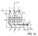
図1は、本発明の2つの実施形態としての照明システムLS1(図1c参照),LS2(図1d参照)を示しており、第1の光ガイドLGai,jが、第1の光エンジンLEai,jの出力を照明システムLS1,LS2のシステム出口窓OS(図1c、図1d及び図1e参照)まで案内する。図1aは、光源として3つの発光ダイオードR,G,Bを有する第1の光エンジンLEai,jの側面図である。動作にあたり、第1の光エンジンLEai,j内のLED−R,G,Bは、各々、他のLED−R,G,Bの任意のものの原色とは異なる原色の光をもたらす。この実施形態では、1つのLED−Rは、赤色光を放出し(これは、赤色LED−Rとしても示されている)、1つのLED−Gは、緑色光を放出し(これは又、緑色LED−Gとして示される)、1つのLED−Bは、青色光を放出する(これは又、青色LED−Bとして示される)。当然のことながら、原色の他の組み合わせも使用できる。各LED−R,G,Bは、長手方向軸線Caを有するコリメータCoを備えている。コリメータCoは、LED−R,G,Bにより放出された光の角度分布をコリメータCoの長手方向軸線Caに対し例えば20°以内、好ましくは15°以内に減少させる。第1の光エンジンLEai,jは、2つのダイクロイックビームスプリッタD1,D2、第1の鏡M1及びエンジン出力窓OEaを更に有している。第1のダイクロイックビームスプリッタD1は、赤色LED−Rにより放出された光を反射し、緑色LED−Gにより放出された光を透過させる。第2のダイクロイックビームスプリッタD2は、青色LED−Bにより放出された光を反射し、緑色LED−Gと赤色LED−Rの両方から放出された光を透過させる。図1aは、光ガイド出力窓OGai,jを備えた第1の光ガイドLEai,jを更に示している。第1の光ガイドLGai,jは、第1の光エンジンLEai,jの光出力を光ガイド出力窓OGai,jまで案内する。 FIG. 1 shows illumination systems LS1 (see FIG. 1c) and LS2 (see FIG. 1d) as two embodiments of the present invention, where the first light guide LGai , j is the first light engine LEa. The output of i, j is guided to the system exit window OS (see FIGS. 1c, 1d and 1e) of the lighting systems LS1, LS2. FIG. 1a is a side view of a first light engine LEa i, j having three light emitting diodes R, G, B as light sources. In operation, the LEDs-R, G, B in the first light engine LEa i, j each provide a light of a primary color that is different from the primary colors of any of the other LEDs-R, G, B. In this embodiment, one LED-R emits red light (which is also shown as red LED-R) and one LED-G emits green light (which is also One LED-B emits blue light (shown as green LED-G) (also shown as blue LED-B). Of course, other combinations of primary colors can be used. Each LED-R, G, B includes a collimator Co having a longitudinal axis Ca. The collimator Co reduces the angular distribution of the light emitted by the LEDs-R, G, and B with respect to the longitudinal axis Ca of the collimator Co, for example, within 20 °, preferably within 15 °. The first light engine LEa i, j further includes two dichroic beam splitters D1, D2, a first mirror M1, and an engine output window OEa. The first dichroic beam splitter D1 reflects the light emitted by the red LED-R and transmits the light emitted by the green LED-G. The second dichroic beam splitter D2 reflects the light emitted by the blue LED-B and transmits the light emitted from both the green LED-G and the red LED-R. FIG. 1 a further shows a first light guide LEa i, j with a light guide output window OGa i, j . The first light guide LGa i, j guides the light output of the first light engine LEa i, j to the light guide output window OGa i, j .
図1aでは、緑色LED−Gにより放出された光の主光路は、実線で示されている。放出された緑色光は、コリメータCoを通過し、このコリメータは、緑色光の角度分布を狭くする。次に、緑色光は、鏡M1で反射してエンジン出力窓OEaの方へ進み、第1のダイクロイックビームスプリッタD1及び第2のダイクロイックビームスプリッタD2を通過する。赤色LED−Rにより放出された光の主光路は、一点鎖線で示されている。放出された赤色光は、コリメータCoを通過し、このコリメータは、赤色光の角度分布を狭くする。次に、赤色光は、ダイクロイックビームスプリッタD1で反射してエンジン出力窓OEaの方へ進み、第2のダイクロイックビームスプリッタD2を通過する。青色LED−Bにより放出された光の主光路は、点線で示されている。放出された青色光は、コリメータCoを通過し、このコリメータは、青色光の角度分布を狭くする。次に、青色光は、ダイクロイックビームスプリッタD2で反射してエンジン出力窓OEaの方へ進む。第1の鏡M1及び2つのダイクロイックビームスプリッタD1,D2の構成により、3つのLED−R,G,Bの各々により放出された光を第1の光エンジンLEai,jの光出力表面OEa上に重ね合わせることができ、緑色光と赤色光と青色光の混色である光出力Sが作られる。光出力Sは、第1の光ガイドLEai,jによって光ガイド出力窓OGai,jまで案内される。第1の光ガイドLEai,jの寸法daは、本発明の範囲から逸脱することなく適用可能である。 In FIG. 1a, the main optical path of the light emitted by the green LED-G is indicated by a solid line. The emitted green light passes through the collimator Co, which narrows the angular distribution of the green light. Next, the green light is reflected by the mirror M1, travels toward the engine output window OEa, and passes through the first dichroic beam splitter D1 and the second dichroic beam splitter D2. The main optical path of the light emitted by the red LED-R is indicated by a one-dot chain line. The emitted red light passes through the collimator Co, which narrows the angular distribution of the red light. Next, the red light is reflected by the dichroic beam splitter D1, travels toward the engine output window OEa, and passes through the second dichroic beam splitter D2. The main optical path of the light emitted by the blue LED-B is indicated by a dotted line. The emitted blue light passes through the collimator Co, which narrows the angular distribution of the blue light. Next, the blue light is reflected by the dichroic beam splitter D2 and travels toward the engine output window OEa. Due to the configuration of the first mirror M1 and the two dichroic beam splitters D1, D2, the light emitted by each of the three LEDs-R, G, B is transmitted on the light output surface OEa of the first light engine LEai , j . And a light output S that is a mixed color of green light, red light, and blue light is produced. The light output S is guided to the light guide output window OGa i, j by the first light guide LEa i, j . Dimension d a of the first light guide LEa i, j can be applied without departing from the scope of the present invention.
図1bは、コリメータ延長部Ceが各コリメータCoの出口に追加された第1の光エンジンLEai,jの側面図である。コリメータの延長により、LEDと鏡M1又はダイクロイックビームスプリッタD1,D2との間の距離の延長が可能である。 FIG. 1 b is a side view of the first light engine LEa i, j in which a collimator extension Ce is added at the exit of each collimator Co. By extending the collimator, the distance between the LED and the mirror M1 or the dichroic beam splitters D1 and D2 can be extended.
図1cは、第1の光エンジンLEa1,1,LEa2,1,LEa3,1のアレイが、光を第1の光ガイドLGa1,1,LGa2,1,LGa3,1のアレイに提供する本発明の照明システムLS1の側面図である。光ガイドLGa1,1,LGa2,1,LGa3,1は、光エンジンLEa1,1,LEa2,1,LEa3,1の各々の出力を光ガイド出力窓OGa1,1,OGa2,1,OGa3,1まで案内する。光ガイドLGa1,1,LGa2,1,LGa3,1の寸法daは、LED−R,G,Bを効果的に冷却することができるよう第1の光エンジンLEa1,1,LEa2,1,LEa3,1の配置を容易にし、しかも、照明システム出口窓OSでの光ガイド出力窓OGa1,1,OGa2,1,OGa3,1の隣接配置を可能にする。図1cに示すような照明システムLS1の実施形態では、各第1光エンジンLEa1,1,LEa2,1,LEa3,1内のLEDは、基板Su1上に配置されている。基板Su1は、ヒートシンクHs1を更に有している。光ガイド出力窓OGa1,1,OGa2,1,OGa3,1のアレイは、照明システムのシステム出口窓OSを形成している。照明システムLS1の正面図が、例えば、図1eに示されている。図1cと図1eの両方から、各第1光エンジンLEa1,1,LEa2,1,LEa3,1が基板Su1を有し、照明システムのシステム出口窓OSが光ガイドOGa1,1…OGa3,4の二次元アレイにより構成されていることは、明らかである。 FIG. 1c shows an array of first light engines LEa 1,1 , LEa 2,1 , LEa 3,1 that emit light into an array of first light guides LGa 1,1 , LGa 2,1 , LGa 3,1 . It is a side view of lighting system LS1 of the present invention provided to. The light guides LGa 1,1 , LGa 2,1 , and LGa 3,1 respectively output the light engines LEa 1,1 , LEa 2,1 , LEa 3,1 to the light guide output windows OGa 1,1 , OGa 2. , 1 and OGa 3,1 . The dimensions d a of the light guides LGa 1,1 , LGa 2,1 , and LGa 3,1 are such that the first light engines LEa 1,1 , LEa can be used to effectively cool the LEDs R, G, B. 2,1 and LEa 3,1 can be easily arranged, and the light guide output windows OGa 1,1 , OGa 2,1 and OGa 3,1 can be arranged adjacent to each other at the illumination system exit window OS. In the embodiment of the illumination system LS1 as shown in FIG. 1c, the LEDs in each first light engine LEa 1,1 , LEa 2,1 , LEa 3,1 are arranged on the substrate Su1. The substrate Su1 further includes a heat sink Hs1. Array of light guide output window OGa 1,1, OGa 2,1, OGa 3,1 forms the system-exit window OS of the lighting system. A front view of the illumination system LS1 is shown, for example, in FIG. 1e. From both FIG. 1c and FIG. 1e, each first light engine LEa 1,1 , LEa 2,1 , LEa 3,1 has a substrate Su1, and the system exit window OS of the lighting system is a light guide OGa 1,1 . It is clear that it is constituted by a two-dimensional array of OGa 3,4 .
図1dは、第1の光エンジンLEa1,1,LEa2,1,LEa3,1のアレイが、光を第1の光ガイドLGa1,1,LGa2,1,LGa3,1のアレイに提供する本発明の別の照明システムLS2の側面図である。この場合も又、光ガイドLGa1,1,LGa2,1,LGa3,1の寸法daは、LED−R,G,Bを効果的に冷却することができるよう第1の光エンジンLEa1,1,LEa2,1,LEa3,1の配置を容易にし、しかも、照明システム出口窓OSでの光ガイド出力窓OGa1,1,OGa2,1,OGa3,1の隣接配置を可能にする。図1dに示されているような照明システムLS2の実施形態では、照明システムLS2の単一の列に配置された第1の光エンジンLEa1,1,LEa2,1,LEa3,1の全てのLEDは、単一の基板Su2上に配置されている。これは、適当なコリメータCoにコリメータ延長部Ceを用いることにより達成されている。基板Su2は、ヒートシンクHs2を更に有している。また、この照明システムLS2では、光ガイド出力窓OGa1,1,OGa2,1,OGa3,1のアレイは、照明システムLS2のシステム出口窓OSを形成している。照明システムLS2の正面図が、例えば、図1eに示されている。図1dと図1eの両方から、各第1光エンジンLEa1,1,LEa2,1,LEa3,1が基板Su2を有し、照明システムのシステム出口窓OSが光ガイドOGa1,1…OGa3,4の二次元アレイにより構成されていることは、明らかであろう。 FIG. 1d shows an array of first light engines LEa 1,1 , LEa 2,1 , LEa 3,1 that emit light into an array of first light guides LGa 1,1 , LGa 2,1 , LGa 3,1 . It is a side view of another lighting system LS2 of the present invention provided in FIG. Again, the light guide LGa 1, 1, LGa 2,1, dimension d a of LGa 3, 1 is, LED-R, G, so that B can effectively cool the first light engine LEa 1 , 1 , LEa 2 , 1 , LEa 3 , 1 can be easily arranged, and the light guide output windows OGa 1,1 , OGa 2 , 1 , OGa 3 , 1 can be arranged adjacent to each other at the illumination system exit window OS. enable. In the embodiment of the lighting system LS2 as shown in FIG. 1d, all of the first light engines LEa 1,1 , LEa 2,1 , LEa 3,1 arranged in a single row of the lighting system LS2 The LEDs are arranged on a single substrate Su2. This is achieved by using a collimator extension Ce in a suitable collimator Co. The substrate Su2 further includes a heat sink Hs2. In the illumination system LS2, the array of light guide output windows OGa 1,1 , OGa 2,1 , OGa 3,1 forms a system exit window OS of the illumination system LS2. A front view of the illumination system LS2 is shown, for example, in FIG. 1e. From both FIG. 1d and FIG. 1e, each first light engine LEa 1,1 , LEa 2,1 , LEa 3,1 has a substrate Su2, and the system exit window OS of the lighting system is a light guide OGa 1,1 . It will be clear that it is constituted by a two-dimensional array of OGa 3,4 .
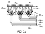
図2は、本発明の照明システムLS3の実施形態を示しており、この実施形態では、第2の光ガイドLGbi,jが、第2の光エンジンLEbi,jの出力を照明システムLS3のシステム出口窓OSの方へ案内する。図2aは、3つの発光ダイオードR,G,Bを有する第2の光エンジンLEbi,jの側面図であり、各発光ダイオードは、他のLED−R,G,Bの任意のものの原色とは異なる原色の光をもたらす。各LED−R,G,Bは、図1aに示された構成と同様に、LED−R,G,Bにより放出された光の角度分布を減少させる。第2の光エンジンLEbi,jは、ダイクロイックプリズムキューブの状態に配置された2つのダイクロイックビームスプリッタD2,D3、第1の鏡M1、第2の鏡M2及びシステム出力窓OEbを更に有している。ダイクロイックビームスプリッタD2は、青色LED−Bにより放出された光を反射し、緑色LED−G及び赤色LED−Rから放出された光を透過させる。第2のダイクロイックビームスプリッタD3は、緑色LED−Gにより放出された光を反射し、青色LED−Bと赤色LED−Rの両方から放出された光を透過させる。図2aは、光ガイド出力窓OGbi,jを有する第2の光ガイドLGbi,jを更に示している。第2の光ガイドLGbi,jは、第2の光エンジンLEbi,jの出力を光ガイド出力窓OGbi,jまで案内する。 FIG. 2 shows an embodiment of the illumination system LS3 according to the invention, in which the second light guide LGb i, j outputs the output of the second light engine LEb i, j of the illumination system LS3. Guide to the system exit window OS. FIG. 2a is a side view of a second light engine LEb i, j having three light emitting diodes R, G, B, each light emitting diode being a primary color of any of the other LEDs-R, G, B. Brings light of different primary colors. Each LED-R, G, B reduces the angular distribution of the light emitted by the LED-R, G, B, similar to the configuration shown in FIG. 1a. The second light engine LEb i, j further comprises two dichroic beam splitters D2, D3, a first mirror M1, a second mirror M2 and a system output window OEb arranged in a dichroic prism cube state. Yes. The dichroic beam splitter D2 reflects the light emitted from the blue LED-B and transmits the light emitted from the green LED-G and the red LED-R. The second dichroic beam splitter D3 reflects the light emitted by the green LED-G and transmits the light emitted from both the blue LED-B and the red LED-R. FIG. 2a further shows a second light guide LGb i, j with a light guide output window OGb i, j . The second light guide LGb i, j guides the output of the second light engine LEb i, j to the light guide output window OGb i, j .
図2aでは、緑色LED−Gにより放出された光の主光路は、実線で示されている。放出された緑色光は、コリメータCoを通過して第2の鏡M2の方へ進み、この第2の鏡は、緑色光をダイクロイックビームスプリッタD3の方へ反射する。ダイクロイックビームスプリッタD3は、緑色光をエンジン出力窓OEbの方へ反射し、この緑色光は、ダイクロイックビームスプリッタD2を通過する。赤色LED−Rにより放出された光の主光路は、一点鎖線で示されている。放出された赤色光は、コリメータCoを通過し、この赤色光は、ダイクロイックビームスプリッタD2及びダイクロイックビームスプリッタD3によりエンジン出力窓OEbの方へ透過される。青色LED−Bにより放出された光の主光路は、点線で示されている。放出された青色光は、コリメータCoを通過して第1の鏡M1の方へ進み、この第1の鏡は、青色光をダイクロイックビームスプリッタD2の方へ反射する。ダイクロイックビームスプリッタD2は、青色光をエンジン出力窓OEbの方へ反射し、この青色光は、ダイクロイックビームスプリッタD3を通過する。第1の鏡M1、第2の鏡M2及び2つのダイクロイックビームスプリッタD2,D3の構成により、3つのLED−R,G,Bの各々により放出された光を第2の光エンジンLEbi,jの光出力表面OEb上に重ね合わせることができ、緑色光と赤色光と青色光の混色である光出力Sが作られる。光出力Sは、第1の光ガイドLEbi,jによって光ガイド出力窓OGbi,jまで案内される。第2の光ガイドLEbi,jの寸法db1,寸法db2は、本発明の範囲から逸脱することなく適用可能である。 In FIG. 2a, the main optical path of the light emitted by the green LED-G is indicated by a solid line. The emitted green light passes through the collimator Co and travels toward the second mirror M2, which reflects the green light toward the dichroic beam splitter D3. The dichroic beam splitter D3 reflects green light toward the engine output window OEb, and this green light passes through the dichroic beam splitter D2. The main optical path of the light emitted by the red LED-R is indicated by a one-dot chain line. The emitted red light passes through the collimator Co, and this red light is transmitted toward the engine output window OEb by the dichroic beam splitter D2 and the dichroic beam splitter D3. The main optical path of the light emitted by the blue LED-B is indicated by a dotted line. The emitted blue light passes through the collimator Co and travels toward the first mirror M1, which reflects the blue light toward the dichroic beam splitter D2. The dichroic beam splitter D2 reflects blue light toward the engine output window OEb, and this blue light passes through the dichroic beam splitter D3. With the configuration of the first mirror M1, the second mirror M2, and the two dichroic beam splitters D2 and D3, the light emitted from each of the three LEDs-R, G, and B is converted into the second light engine LEb i, j. The light output S, which is a mixed color of green light, red light and blue light, can be produced. The light output S is guided to the light guide output window OGb i, j by the first light guide LEb i, j . The dimension d b1 and dimension d b2 of the second light guide LEb i, j are applicable without departing from the scope of the present invention.
図2bは、第2の光エンジンLEb1,1,LEb2,1,LEb3,1のアレイが、光を第2の光ガイドLGb1,1,LGb2,1,LGb3,1のアレイに提供する本発明の照明システムLS3の側面図である。光ガイドLGb1,1,LGb2,1,LGb3,1は、第2の光エンジンLEb1,1,LEb2,1,LEb3,1の各々の出力を光ガイド出力窓OGb1,1,OGb2,1,OGb3,1まで案内する。光ガイドLGb1,1,LGb2,1,LGb3,1の寸法db1,db2は、LED−R,G,Bを効果的に冷却することができるよう第2の光エンジンLEb1,1,LEb2,1,LEb3,1の配置を可能にし、しかも、照明システム出口窓OSでの光ガイド出力窓OGb1,1,OGb2,1,OGb3,1の隣接配置を可能にする。図2Bに示す実施形態では、第2の光エンジンLEb1,1,LEb2,1,LEb3,1の全てのLEDは、単一の基板Su3上に配置されている。基板Su3は、ヒートシンクHs3を更に有している。光ガイド出力窓OGb1,1,OGb2,1,OGb3,1のアレイは、照明システムのシステム出口窓OSを形成している。照明システムLS3の正面図が、例えば、図2cに示されている。図2bと図2cの両方から、図2に示す実施形態では、各第2光エンジンLEb1,1,LEb2,1,LEb3,1が基板Su3を有し、照明システムLS3のシステム出口窓OSが光ガイドOGb1,1…OGb3,4の二次元アレイにより構成されていることは、明らかであろう。 FIG. 2b shows an array of second light engines LEb 1,1 , LEb 2,1 , LEb 3,1 that emit light into an array of second light guides LGb 1,1 , LGb 2,1 , LGb 3,1 . It is a side view of lighting system LS3 of the present invention provided to. The light guides LGb 1,1 , LGb 2,1 , LGb 3,1 send the outputs of the second light engines LEb 1,1 , LEb 2,1 , LEb 3,1 to the light guide output window OGb 1,1. , OGb 2,1 and OGb 3,1 . The dimensions d b1 and d b2 of the light guides LGb 1,1 , LGb 2,1 , LGb 3,1 are the second light engines LEb 1, so that the LEDs R, G, B can be cooled effectively . 1 , LEb 2,1 , LEb 3,1 can be arranged, and the light guide output windows OGb 1,1 , OGb 2,1 , OGb 3,1 can be arranged adjacent to each other in the lighting system exit window OS. To do. In the embodiment shown in FIG. 2B, all the LEDs of the second light engines LEb 1,1 , LEb 2,1 , LEb 3,1 are arranged on a single substrate Su3. The substrate Su3 further includes a heat sink Hs3. The array of light guide output windows OGb 1,1 , OGb 2,1 , OGb 3,1 forms a system exit window OS of the illumination system. A front view of the illumination system LS3 is shown, for example, in FIG. 2c. From both Figure 2b and Figure 2c, in the embodiment shown in FIG. 2, each of the second light engine LEb 1,1, LEb 2,1, LEb 3,1 has a substrate Su3, the system-exit window of the illumination system LS3 It will be apparent that the OS is constituted by a two-dimensional array of light guides OGb 1,1 ... OGb 3,4 .
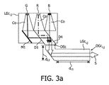
図3は、本発明の照明システムLS4の実施形態を示しており、この実施形態では、第3の光ガイドLGci,jが、第3の光エンジンLEci,jの出力を照明システムLS4のシステム出口窓OSの方へ案内する。図3aは、3つの発光ダイオードR,G,Bを有する第3の光エンジンLEci,jの側面図であり、各発光ダイオードは、他のLED−R,G,Bの任意のものの原色とは異なる原色の光をもたらす。各LED−R,G,Bは、図1a及び図2aに示された構成と同じく、LED−R,G,Bにより放出された光の角度分布を減少させる。第3の光エンジンLEci,jは、2つのダイクロイックビームスプリッタD1,D4、第1の鏡M1及びシステム出力窓OEcを更に有している。ダイクロイックビームスプリッタD1は、赤色LED−Rにより放出された光を反射し、緑色LED−Gから放出された光を透過させる。第2のダイクロイックビームスプリッタD4は、緑色LED−Gと赤色LED−Rの両方により放出された光を反射し、青色LED−Bから放出された光を透過させる。図3aは、光ガイド出力窓OGci,jを有する第3の光ガイドLGci,jを更に示している。第3の光ガイドLGci,jは、一次元に配置された光エンジンLEci,j(図3c参照)の出力を光ガイド出力窓OGci,jまで案内する。 FIG. 3 shows an embodiment of the illumination system LS4 according to the invention, in which the third light guide LGc i, j outputs the output of the third light engine LEc i, j of the illumination system LS4. Guide to the system exit window OS. FIG. 3a is a side view of a third light engine LEc i, j having three light emitting diodes R, G, B, each light emitting diode being a primary color of any of the other LEDs-R, G, B Brings light of different primary colors. Each LED-R, G, B reduces the angular distribution of the light emitted by the LED-R, G, B, similar to the configuration shown in FIGS. 1a and 2a. The third light engine LEc i, j further includes two dichroic beam splitters D1, D4, a first mirror M1, and a system output window OEc. The dichroic beam splitter D1 reflects the light emitted from the red LED-R and transmits the light emitted from the green LED-G. The second dichroic beam splitter D4 reflects the light emitted by both the green LED-G and the red LED-R and transmits the light emitted from the blue LED-B. FIG. 3a further shows a third light guide LGc i, j with a light guide output window OGc i, j . The third light guide LGc i, j guides the output of the light engine LEc i, j (see FIG. 3c) arranged one-dimensionally to the light guide output window OGc i, j .
図3aでは、緑色LED−Gにより放出された光の主光路は、実線で示されている。放出された緑色光は、コリメータCoを通過し、第1の鏡M1の方へ進み、この第1の鏡は、緑色光をダイクロイックビームスプリッタD4の方へ反射し、この緑色光は、ダイクロイックビームスプリッタD1を通過する。ダイクロイックビームスプリッタD4は、緑色光を第3の光エンジンLEci,jのエンジン出力窓OEcの方へ反射する。赤色LED−Rにより放出された光の主光路は、一点鎖線で示されている。放出された赤色光は、コリメータCoを通過してダイクロイックビームスプリッタD1の方へ進み、このダイクロイックビームスプリッタは、赤色光をダイクロイックビームスプリッタD4の方へ反射する。ダイクロイックビームスプリッタD4は、赤色光をエンジン出力窓OEcの方へ反射する。青色LED−Bにより放出された光の主光路は、点線で示されている。放出された青色光は、コリメータCoを通過し、ダイクロイックビームスプリッタD4によりエンジン出力窓OEcの方へ透過される。第1の鏡M1及び2つのダイクロイックビームスプリッタD1,D4の構成により、3つのLED−R,G,Bの各々により放出された光を第3の光エンジンLEci,jの光出力表面OEc上に重ね合わせることができ、緑色光と赤色光と青色光の混色である光出力Sが作られる。光出力Sは、第3の光ガイドLEci,jによって光ガイド出力窓OGci,jまで案内される。 In FIG. 3a, the main optical path of the light emitted by the green LED-G is indicated by a solid line. The emitted green light passes through the collimator Co and travels toward the first mirror M1, which reflects the green light toward the dichroic beam splitter D4, which is the dichroic beam. Passes through the splitter D1. The dichroic beam splitter D4 reflects the green light toward the engine output window OEc of the third light engine LEci , j . The main optical path of the light emitted by the red LED-R is indicated by a one-dot chain line. The emitted red light passes through the collimator Co and travels toward the dichroic beam splitter D1, and the dichroic beam splitter reflects the red light toward the dichroic beam splitter D4. The dichroic beam splitter D4 reflects red light toward the engine output window OEc. The main optical path of the light emitted by the blue LED-B is indicated by a dotted line. The emitted blue light passes through the collimator Co and is transmitted toward the engine output window OEc by the dichroic beam splitter D4. With the configuration of the first mirror M1 and the two dichroic beam splitters D1, D4, the light emitted by each of the three LEDs-R, G, B is reflected on the light output surface OEc of the third light engine LEci , j. And a light output S that is a mixed color of green light, red light, and blue light is produced. The light output S is guided to the light guide output window OGc i, j by the third light guide LEc i, j .
図3bは、第3の光エンジンLEc1,1,LEc2,1,LEc3,1のアレイが光を第3の光ガイドLGc1,1,LGc2,1,LGc3,1のアレイに提供する本発明の照明システムLS4の実施形態の側面図である。図示の実施形態では、各光ガイドLGc1,1,LGc2,1,LGc3,1は、第3の光エンジンLEc1,j,LEc2,j,LGc3,j(LEc1,jだけが図3cに示されている)の一次元構成の出力を光ガイド出力窓OGc1,1,OGc2,1,OGc3,1まで案内する。光ガイドLGc1,1,LGc2,1,LGc3,1の寸法dc,1,dc,2は、LED−R,G,Bを効果的に冷却することができるよう第3の光エンジンLEc1,1,LEc2,1,LEc3,1の配置を可能にし、しかも、照明システムLS4のシステム出口窓OSでの光ガイド出力窓OGc1,1,OGc2,1,OGc3,1の隣接配置を可能にする。図3bに示す実施形態では、第3の光エンジンLEc1,j,LEc2,j,LEc3,jの一次元構成のLEDは、単一の基板Su4上に配置されている。基板Su4は、ヒートシンクHs4を更に有している。光ガイド出力窓OGc1,1,OGc2,1,OGc3,1のアレイは、照明システムLS4のシステム出口窓OSを形成している。例えば、照明システムLS4の正面図が、図3cに示されている。 FIG. 3b shows that an array of third light engines LEc 1,1 , LEc 2,1 , LEc 3,1 directs light into an array of third light guides LGc 1,1 , LGc 2,1 , LGc 3,1 . It is a side view of embodiment of the illumination system LS4 of this invention to provide. In the illustrated embodiment, each light guide LGc 1,1 , LGc 2,1 , LGc 3,1 is a third light engine LEc 1, j , LEc 2, j , LGc 3, j (only LEc 1, j Is guided to the light guide output windows OGc 1,1 , OGc 2,1 , OGc 3,1 ( shown in FIG. 3c). Light guide LGc 1,1, LGc 2,1, dimension d c, 1, d c, 2 of LGc 3, 1 is, LED-R, G, the third light so that B can be effectively cooled The arrangement of the engines LEc 1,1 , LEc 2,1 , LEc 3,1 is possible, and the light guide output windows OGc 1,1 , OGc 2,1 , OGc 3, at the system exit window OS of the illumination system LS4 Allows 1 adjacent placement. In the embodiment shown in FIG. 3b, the one-dimensional LEDs of the third light engine LEc 1, j , LEc 2, j , LEc 3, j are arranged on a single substrate Su4. The substrate Su4 further includes a heat sink Hs4. The array of light guide output windows OGc 1,1 , OGc 2,1 , OGc 3,1 forms the system exit window OS of the illumination system LS4. For example, a front view of the lighting system LS4 is shown in FIG. 3c.
図3cは、図3bに示す照明システムLS4の実施形態の正面図である。 FIG. 3c is a front view of the embodiment of the illumination system LS4 shown in FIG. 3b.
図4は、本発明のランプL及びディスプレイ装置DDを示している。図4aは、カバーLc、冷却区分C、ヒンジH及び出口窓OLを有するランプLを示している。ランプLの出口窓OLは、本発明の照明システムのLS1,LS2,LS3,LS4のシステム出口窓OSを有している。先の図に示されている照明システムのヒートシンクHs1,Hs2,Hs3,Hs4は、カバーLcの冷却区分Cに集中して配置されている。代表的には、冷却区分Cは、向上した冷却特性がカバーLcのその部分に割り当てるよう設計されている。 FIG. 4 shows the lamp L and the display device DD of the present invention. FIG. 4a shows a lamp L having a cover Lc, a cooling section C, a hinge H and an exit window OL. The exit window OL of the lamp L has the system exit window OS of LS1, LS2, LS3, LS4 of the illumination system of the present invention. The heat sinks Hs1, Hs2, Hs3, and Hs4 of the lighting system shown in the previous figure are concentrated on the cooling section C of the cover Lc. Typically, the cooling section C is designed such that improved cooling characteristics are assigned to that part of the cover Lc.
図4bは、ディスプレイDi及びディスプレイDiを照明するための本発明の照明システムLS1,LS2,LS3,LS4を有するディスプレイ装置DDを示している。ディスプレイ装置DDのディスプレイDiは、例えば、液晶パネルであっても良く、或いは、例えば、ビルボードで用いられる部分的に透明なピクチャであっても良い。 FIG. 4b shows a display device DD having a display Di and a lighting system LS1, LS2, LS3, LS4 of the invention for illuminating the display Di. The display Di of the display device DD may be a liquid crystal panel, for example, or may be a partially transparent picture used on a billboard, for example.
第1の光ガイドLGai,j、第2の光ガイドLGbi,j及び第3の光ガイドLgci,jは、本発明の照明システムLS1,LS2,LS3,LS4で用いられた光ガイドの実施形態である。光ガイドLGai,j,LGbi,j,LGci,jは、光ガイドLEai,j,LEbi,j,LEci,j内のLED−R,G,Bをシステム出口窓OSから見て遠くに配置できるように光ガイドLEai,j,LEbi,j,LEci,jを照明システムLS1,LS2,LS3,LS4内に配置でき、それにより、LEDを効果的に冷却することができると共に照明システムLS1,LS2,LS3,LS4のシステム出口窓OSでの光ガイド出力窓OGai,j,OGbi,j,OGci,jの隣接構成を可能にする。光ガイドLGai,j,LGbi,j,LGci,jは、例えば、光エンジンLEai,j,LEbi,j,LEci,jの光出力Sを全反射により閉じ込める誘電体材料から成っている。誘電体材料は、可撓性であっても良く、剛性であっても良い。 The first light guide LGa i, j , the second light guide LGb i, j and the third light guide Lgc i, j are the light guides used in the illumination systems LS1, LS2, LS3 and LS4 of the present invention. It is an embodiment. Light guide LGa i, j, LGb i, j, LGc i, j is looked light guide LEa i, j, LEb i, j, LEc i, LED-R in j, G, and B from the system-exit window OS The light guides LEa i, j , LEb i, j , LEc i, j can be arranged in the illumination systems LS1, LS2, LS3, LS4 so that the LEDs can be effectively cooled. In addition, the light guide output windows OGa i, j , OGb i, j , OGc i, j at the system exit window OS of the illumination systems LS1, LS2, LS3, LS4 can be configured adjacently. The light guides LGai , j , LGbi , j , LGci , j are made of a dielectric material that confines the light output S of the light engines LEai , j , LEbi , j , LEci , j by total reflection, for example. ing. The dielectric material may be flexible or rigid.
光エンジンLEai,j,LEbi,j,LEci,jと光ガイドLGai,j,LGbi,j,LGci,jの種々の組み合わせは、本発明の範囲から逸脱することなく、当業者によって設計できる。 Various combinations of the light engines LEa i, j , LEb i, j , LEc i, j and the light guides LGai , j , LGb i, j , LGc i, j can be used without departing from the scope of the present invention. Can be designed by contractors.
LEDは、互いに異なる原色の光源、例えば、周知の赤色(R)光エミッタ、緑色(G)光エミッタ又は青色(B)光エミッタであるのが良い。加うるに、光エミッタは、例えば、原色としてアンバー色、マゼンタ色又はシアン色を有しても良い。これら原色を発光ダイオードチップにより直接発生させても良く、又は、発光ダイオードチップからの光による照射時に蛍光体により生じさせても良い。 The LEDs may be light sources of different primary colors, such as the well-known red (R) light emitter, green (G) light emitter or blue (B) light emitter. In addition, the light emitter may have, for example, amber, magenta or cyan as the primary color. These primary colors may be generated directly by the light emitting diode chip, or may be generated by the phosphor upon irradiation with light from the light emitting diode chip.
上述の実施形態は、本発明を限定するものではなく、当業者であれば、特許請求の範囲に記載された本発明の範囲から逸脱することなく多くの変形実施形態を設計できることは注目されるべきである。 It is noted that the above-described embodiments are not intended to limit the present invention, and that a person skilled in the art can design many modified embodiments without departing from the scope of the present invention described in the claims. Should.
特許請求の範囲において、括弧の中にある参照符号は、本発明を限定するものと解釈されてはならない。原文において、動詞“comprise”及びその活用形の使用は、特許請求の範囲に記載された要素又はステップ以外の要素又はステップの存在を排除するものではない。要素の前に位置する冠詞“a”又は“an”は、かかる要素が複数個あることを排除するものではない。幾つかの手段を列挙している装置クレームでは、これら手段の幾つかは、同一のハードウェアで具体化できる。或る特定の手段が相互に異なる従属形式の請求項に記載されているという単なる事実によっては、これら手段の組み合わせを有利に使用することはできないということを意味するものではない。 In the claims, any reference signs placed between parentheses shall not be construed as limiting the invention. In the text, the use of the verb “comprise” and its conjugations does not exclude the presence of elements or steps other than those stated in a claim. The article “a” or “an” preceding an element does not exclude the presence of a plurality of such elements. In the device claim enumerating several means, several of these means can be embodied by one and the same hardware. The mere fact that certain measures are recited in mutually different dependent claims does not indicate that a combination of these measured cannot be used to advantage.
Claims (13)
各光エンジン(LEai,j,LEbi,j,LEci,j)は、第1の所定数(N)の発光ダイオード(R,G,B)を有し、前記発光ダイオード(R,G,B)は、同一の光エンジン(LEai,j,LEbi,j,LEci,j)中の他の発光ダイオード(R,G,B)の任意のものの原色とは異なる原色の光を放出し、各発光ダイオード(R,G,B)は、長手方向軸線(Ca)を備えたコリメータ(Co)を備え、各光エンジン(LEai,j,LEbi,j,LEci,j)は、第2の所定数(M)のダイクロイックビームスプリッタ(D1,D2;D2,D3;D1,D4)及びエンジン出力窓(OEa,OEb,OEc)を更に有し、前記発光ダイオード(R,G,B)の各々によって放出された光は、前記ダイクロイックビームスプリッタ(D1,D2;D2,D3;D1,D4)の少なくとも1つを介して前記エンジン出力窓(OEa,OEb,OEc)上に重ね合わされ、
前記照明システム(LS1,LS2,LS3,LS4)は、前記光エンジン(LEai,j,LEbi,j,LEci,j)によって放出された光を前記システム出口窓(OS)の方へ案内する複数個の光ガイド(LGai,j,LGbi,j,LGci,j)を更に有し、
各光ガイド(LGai,j,LGbi,j,LGci,j)は、光ガイド出力窓(OGai,j,OGbi,j,OGci,j)を有し、
前記システム出口窓(OS)は、光ガイド出力窓(OGai,j,OGbi,j,OGci,j)のアレイによって構成されている、
ことを特徴とする照明システム(LS1,LS2,LS3,LS4)。 A lighting system (LS1, LS2, LS3, LS4) having a plurality of light engines (LEa i, j , LEb i, j , LEc i, j ) and a system exit window (OS),
Each light engine (LEa i, j , LEb i, j , LEc i, j ) has a first predetermined number (N) of light emitting diodes (R, G, B), and said light emitting diodes (R, G , B) emits light of a primary color different from the primary colors of any of the other light emitting diodes (R, G, B) in the same light engine (LEa i, j , LEb i, j , LEc i, j ). Each emitting light emitting diode (R, G, B) comprises a collimator (Co) with a longitudinal axis (Ca) and each light engine (LEa i, j , LEb i, j , LEc i, j ). Further includes a second predetermined number (M) of dichroic beam splitters (D1, D2; D2, D3; D1, D4) and engine output windows (OEa, OEb, OEc), and the light emitting diodes (R, G). , B) is emitted by each of the dichroic beam splitters (D1, 2; D2, D3; D1, D4) of said engine output window via at least one 1 (OEa, OEb, OEc) superimposed on,
The lighting system (LS1, LS2, LS3, LS4) guides the light emitted by the light engine (LEa i, j , LEb i, j , LEc i, j ) towards the system exit window (OS). A plurality of light guides (LGai , j , LGbi , j , LGci , j ),
Each light guide (LGai , j , LGbi , j , LGci , j ) has a light guide output window (OGai , j , OGbi , j , OGci , j ),
The system exit window (OS) is constituted by an array of light guide output windows (OGai , j , OGbi , j , OGci , j ).
A lighting system (LS1, LS2, LS3, LS4).
請求項1記載の照明システム(LS1,LS2,LS3,LS4)。 The light emitting diodes (R, G, B) in each light engine (LEa i, j , LEb i, j , LEc i, j ) are arranged along a straight line substantially perpendicular to the longitudinal axis (Ca). ing,
The illumination system (LS1, LS2, LS3, LS4) according to claim 1.
請求項2に記載の照明システム(LS1,LS2,LS3,LS4)。 The light emitting diodes (R, G, B) in each light engine (LEa i, j , LEb i, j , LEc i, j ) are arranged on a single substrate (Su1).
The illumination system (LS1, LS2, LS3, LS4) according to claim 2.
請求項3に記載の照明システム(LS1,LS2,LS3,LS4)。 The substrates (Su1, Su2) of the light engines (LEa i, j , LEb i, j , LEc i, j ) are arranged in parallel to each other,
The illumination system (LS1, LS2, LS3, LS4) according to claim 3.
請求項2に記載の照明システム(LS1,LS2,LS3,LS4)。 The light emitting diodes (R, G, B) of all the light engines (LEa i, j , LEb i, j , LEc i, j ) are arranged on a single substrate (Su3).
The illumination system (LS1, LS2, LS3, LS4) according to claim 2.
請求項1又は2に記載の照明システム(LS1,LS2,LS3,LS4)。 The light guide output windows (OGai , j , OGbi , j , OGci , j ) are disposed in the array to form a surface that substantially covers the system exit window (OS);
The illumination system (LS1, LS2, LS3, LS4) according to claim 1 or 2.
請求項1又は2に記載の照明システム(LS1,LS2,LS3,LS4)。 A light guide (LGai , j , LGbi , j , LGci , j ) emits light emitted by a plurality of light engines (LEai , j , LEbi , j , LEci , j ) at the system exit. Guide to the window (OS),
The illumination system (LS1, LS2, LS3, LS4) according to claim 1 or 2.
請求項1又は2に記載の照明システム(LS1,LS2,LS3,LS4)。 Each collimator (Co) reduces the angular distribution of light emitted by the light emitting diodes (R, G, B) within 20 ° with respect to the longitudinal axis (Ca) of the collimator (Co).
The illumination system (LS1, LS2, LS3, LS4) according to claim 1 or 2.
請求項8に記載の照明システム(LS1,LS2,LS3,LS4)。 Each light guide (LGai , j , LGbi , j , LGci , j ) is a rigid light guide (LGai , j , LGb) that substantially maintains the light distribution of the light from the collimator (Co). i, j , LGc i, j )
The lighting system (LS1, LS2, LS3, LS4) according to claim 8.
請求項1又は2に記載の照明システム(LS1,LS2,LS3,LS4)。 Having at least two dichroic beam splitters (D1, D2; D2, D3; D1, D4), the two dichroic beam splitters (D2, D3) are combined in a single beam splitter cube (Cu) state Yes,
The illumination system (LS1, LS2, LS3, LS4) according to claim 1 or 2.
請求項1又は2に記載の照明システム(LS1,LS2,LS3,LS4)。 Each light engine (LEa i, j , LEb i, j , LEc i, j ) has three light emitting diodes (R, G, B),
The illumination system (LS1, LS2, LS3, LS4) according to claim 1 or 2.
Applications Claiming Priority (2)
| Application Number | Priority Date | Filing Date | Title |
|---|---|---|---|
| EP05102917 | 2005-04-13 | ||
| PCT/IB2006/051099 WO2006120586A2 (en) | 2005-04-13 | 2006-04-11 | Lighting system comprising 2d led stack |
Publications (2)
| Publication Number | Publication Date |
|---|---|
| JP2008536283A true JP2008536283A (en) | 2008-09-04 |
| JP2008536283A5 JP2008536283A5 (en) | 2009-05-28 |
Family
ID=37396942
Family Applications (1)
| Application Number | Title | Priority Date | Filing Date |
|---|---|---|---|
| JP2008506027A Abandoned JP2008536283A (en) | 2005-04-13 | 2006-04-11 | Illumination system with 2DLED stack |
Country Status (6)
| Country | Link |
|---|---|
| US (1) | US20080205077A1 (en) |
| EP (1) | EP1875300A2 (en) |
| JP (1) | JP2008536283A (en) |
| CN (1) | CN101160544A (en) |
| TW (1) | TW200734747A (en) |
| WO (1) | WO2006120586A2 (en) |
Cited By (3)
| Publication number | Priority date | Publication date | Assignee | Title |
|---|---|---|---|---|
| JP2010045032A (en) * | 2008-08-15 | 2010-02-25 | Christie Digital Systems Usa Inc | Light integrator and light integrating system |
| JP2012525681A (en) * | 2009-04-30 | 2012-10-22 | イーストマン コダック カンパニー | Beam alignment room with diffusion correction function |
| JP2020514832A (en) * | 2017-03-21 | 2020-05-21 | マジック リープ, インコーポレイテッドMagic Leap,Inc. | Method, device and system for illuminating a spatial light modulator |
Families Citing this family (17)
| Publication number | Priority date | Publication date | Assignee | Title |
|---|---|---|---|---|
| US7846391B2 (en) | 2006-05-22 | 2010-12-07 | Lumencor, Inc. | Bioanalytical instrumentation using a light source subsystem |
| US8098375B2 (en) | 2007-08-06 | 2012-01-17 | Lumencor, Inc. | Light emitting diode illumination system |
| KR20100127284A (en) * | 2008-03-19 | 2010-12-03 | 아이2아이씨 코포레이션 | Photoluminescent light source |
| US8466436B2 (en) | 2011-01-14 | 2013-06-18 | Lumencor, Inc. | System and method for metered dosage illumination in a bioanalysis or other system |
| CA2829306C (en) * | 2011-03-08 | 2017-02-14 | Novadaq Technologies Inc. | Full spectrum led illuminator |
| US10585293B2 (en) * | 2011-10-17 | 2020-03-10 | Appotronics Corporation Limited | Light source and display system |
| US8967811B2 (en) | 2012-01-20 | 2015-03-03 | Lumencor, Inc. | Solid state continuous white light source |
| US9217561B2 (en) | 2012-06-15 | 2015-12-22 | Lumencor, Inc. | Solid state light source for photocuring |
| US9651231B2 (en) * | 2012-10-04 | 2017-05-16 | Guardian Industries Corp. | Laminated LED array and/or products including the same |
| US9956752B2 (en) * | 2012-10-04 | 2018-05-01 | Guardian Glass, LLC | Methods of making laminated LED array and/or products including the same |
| US9696012B2 (en) | 2012-10-04 | 2017-07-04 | Guardian Industries Corp. | Embedded LED assembly with optional beam steering optical element, and associated products, and/or methods |
| DE102013104046A1 (en) * | 2013-04-22 | 2014-10-23 | Osram Opto Semiconductors Gmbh | Optical arrangement and display device |
| TWI512334B (en) * | 2013-11-28 | 2015-12-11 | Delta Electronics Inc | Light source system and display apparatus comprising the same |
| EP3423877B1 (en) * | 2016-02-29 | 2022-10-26 | Magic Leap, Inc. | Virtual and augmented reality systems and methods |
| US10712775B2 (en) * | 2016-12-06 | 2020-07-14 | Facebook Technologies, Llc | Dichroic combiner backlight used in a head mounted display |
| CN109521599B (en) * | 2017-09-18 | 2021-10-22 | 宏碁股份有限公司 | Side light type backlight module, display device and backlight control method thereof |
| CN113900241B (en) * | 2021-10-18 | 2023-06-30 | 中国科学院光电技术研究所 | Integrated wide-spectrum double-view-field off-axis optical system sharing secondary mirror |
Family Cites Families (11)
| Publication number | Priority date | Publication date | Assignee | Title |
|---|---|---|---|---|
| US5654775A (en) * | 1995-12-27 | 1997-08-05 | Philips Electronics North America Corporation | Three lamp, three light valve projection system |
| US6036340A (en) * | 1998-03-03 | 2000-03-14 | Ford Global Technologies, Inc. | Dimpled manifold optical element for a vehicle lighting system |
| US6273589B1 (en) * | 1999-01-29 | 2001-08-14 | Agilent Technologies, Inc. | Solid state illumination source utilizing dichroic reflectors |
| US6224216B1 (en) * | 2000-02-18 | 2001-05-01 | Infocus Corporation | System and method employing LED light sources for a projection display |
| JP2003068115A (en) * | 2001-08-30 | 2003-03-07 | Koito Mfg Co Ltd | Luminaire for vehicle |
| KR100403599B1 (en) * | 2001-11-06 | 2003-10-30 | 삼성전자주식회사 | Illumination system and a projection system imploying it |
| EP2402797A3 (en) * | 2001-12-14 | 2012-08-08 | QUALCOMM MEMS Technologies, Inc. | Uniform illumination system |
| JP2004335992A (en) * | 2003-04-18 | 2004-11-25 | Victor Co Of Japan Ltd | Light source unit and projection display device applied with the light source unit |
| EP1636782A1 (en) * | 2003-06-13 | 2006-03-22 | Koninklijke Philips Electronics N.V. | Lcd display panel including segmented illumination scheme by scrolling illumination of the corresponding panel segments |
| EP1639402A1 (en) * | 2003-06-24 | 2006-03-29 | Koninklijke Philips Electronics N.V. | Method and apparatus for recycling reflected light in optical systems as e.g. projection display |
| US7234820B2 (en) * | 2005-04-11 | 2007-06-26 | Philips Lumileds Lighting Company, Llc | Illuminators using reflective optics with recycling and color mixing |
-
2006
- 2006-04-11 JP JP2008506027A patent/JP2008536283A/en not_active Abandoned
- 2006-04-11 EP EP06765657A patent/EP1875300A2/en not_active Withdrawn
- 2006-04-11 WO PCT/IB2006/051099 patent/WO2006120586A2/en not_active Application Discontinuation
- 2006-04-11 TW TW095112905A patent/TW200734747A/en unknown
- 2006-04-11 CN CNA2006800120651A patent/CN101160544A/en active Pending
- 2006-04-11 US US11/911,025 patent/US20080205077A1/en not_active Abandoned
Cited By (6)
| Publication number | Priority date | Publication date | Assignee | Title |
|---|---|---|---|---|
| JP2010045032A (en) * | 2008-08-15 | 2010-02-25 | Christie Digital Systems Usa Inc | Light integrator and light integrating system |
| JP2012525681A (en) * | 2009-04-30 | 2012-10-22 | イーストマン コダック カンパニー | Beam alignment room with diffusion correction function |
| JP2020514832A (en) * | 2017-03-21 | 2020-05-21 | マジック リープ, インコーポレイテッドMagic Leap,Inc. | Method, device and system for illuminating a spatial light modulator |
| US11567320B2 (en) | 2017-03-21 | 2023-01-31 | Magic Leap, Inc. | Methods, devices, and systems for illuminating spatial light modulators |
| JP7249285B2 (en) | 2017-03-21 | 2023-03-30 | マジック リープ, インコーポレイテッド | Methods, devices and systems for illuminating spatial light modulators |
| US11835723B2 (en) | 2017-03-21 | 2023-12-05 | Magic Leap, Inc. | Methods, devices, and systems for illuminating spatial light modulators |
Also Published As
| Publication number | Publication date |
|---|---|
| WO2006120586A3 (en) | 2007-03-08 |
| WO2006120586A2 (en) | 2006-11-16 |
| EP1875300A2 (en) | 2008-01-09 |
| CN101160544A (en) | 2008-04-09 |
| TW200734747A (en) | 2007-09-16 |
| US20080205077A1 (en) | 2008-08-28 |
Similar Documents
| Publication | Publication Date | Title |
|---|---|---|
| JP2008536283A (en) | Illumination system with 2DLED stack | |
| JP6361333B2 (en) | Light source device and optical engine | |
| US9323045B2 (en) | Illumination device and projector | |
| US8628199B2 (en) | Light source device with a plurality of light sources and a collimating lens | |
| US8823886B2 (en) | Lighting Device and Projector | |
| US11829058B2 (en) | Light source device and image projection apparatus including a rod integrator and light guide | |
| US9249949B2 (en) | Lighting device and projection-type display device using the same including a color-combining prism | |
| JP5914878B2 (en) | Light source device and projection display device | |
| JP5875865B2 (en) | Device for recycling light to increase the brightness of light output, and LED projector incorporating the device | |
| US10175566B2 (en) | Light source device, illumination device, and projector | |
| US7883238B2 (en) | Light collimation and mixing of remote light sources | |
| US20180149955A1 (en) | Illumination device and projector | |
| US10705416B2 (en) | Wavelength conversion element, light source apparatus, and projector | |
| US9989237B2 (en) | Light source device | |
| US20070242231A1 (en) | Illumination system and projection apparatus | |
| KR101583823B1 (en) | Light illumination unit and projection light illumination apparatus having thesame | |
| JP2009545846A (en) | Light emitting device | |
| US8371712B2 (en) | Light source module of projector | |
| CN112859499B (en) | Light source device and projector | |
| US20230238780A1 (en) | Light-emitting device and light-emitting system | |
| JP2005084633A (en) | Light source device and projection type display device |
Legal Events
| Date | Code | Title | Description |
|---|---|---|---|
| A521 | Written amendment |
Free format text: JAPANESE INTERMEDIATE CODE: A523 Effective date: 20090408 |
|
| A621 | Written request for application examination |
Free format text: JAPANESE INTERMEDIATE CODE: A621 Effective date: 20090408 |
|
| A762 | Written abandonment of application |
Free format text: JAPANESE INTERMEDIATE CODE: A762 Effective date: 20091104 |