JP2008531412A - container - Google Patents
container Download PDFInfo
- Publication number
- JP2008531412A JP2008531412A JP2007557061A JP2007557061A JP2008531412A JP 2008531412 A JP2008531412 A JP 2008531412A JP 2007557061 A JP2007557061 A JP 2007557061A JP 2007557061 A JP2007557061 A JP 2007557061A JP 2008531412 A JP2008531412 A JP 2008531412A
- Authority
- JP
- Japan
- Prior art keywords
- wall
- sealing portion
- sealing
- cutback
- cover
- Prior art date
- Legal status (The legal status is an assumption and is not a legal conclusion. Google has not performed a legal analysis and makes no representation as to the accuracy of the status listed.)
- Ceased
Links
- 238000007789 sealing Methods 0.000 claims abstract description 222
- 239000000463 material Substances 0.000 claims description 5
- 229920008790 Amorphous Polyethylene terephthalate Polymers 0.000 claims description 4
- 229920008651 Crystalline Polyethylene terephthalate Polymers 0.000 claims description 4
- 229920001903 high density polyethylene Polymers 0.000 claims description 4
- 239000004700 high-density polyethylene Substances 0.000 claims description 4
- 229920001684 low density polyethylene Polymers 0.000 claims description 4
- 239000004702 low-density polyethylene Substances 0.000 claims description 4
- 239000004417 polycarbonate Substances 0.000 claims description 4
- 239000004800 polyvinyl chloride Substances 0.000 claims description 4
- 229920000915 polyvinyl chloride Polymers 0.000 claims description 4
- 239000004743 Polypropylene Substances 0.000 claims description 3
- 239000004793 Polystyrene Substances 0.000 claims description 3
- -1 polypropylene Polymers 0.000 claims description 3
- 229920001155 polypropylene Polymers 0.000 claims description 3
- 229920000515 polycarbonate Polymers 0.000 claims description 2
- 229920002223 polystyrene Polymers 0.000 claims description 2
- 230000008878 coupling Effects 0.000 claims 1
- 238000010168 coupling process Methods 0.000 claims 1
- 238000005859 coupling reaction Methods 0.000 claims 1
- 239000006260 foam Substances 0.000 claims 1
- 238000000926 separation method Methods 0.000 abstract description 6
- 238000010411 cooking Methods 0.000 abstract description 2
- 230000008901 benefit Effects 0.000 description 11
- 230000000694 effects Effects 0.000 description 9
- 238000003860 storage Methods 0.000 description 6
- 238000000034 method Methods 0.000 description 2
- 230000000007 visual effect Effects 0.000 description 2
- 239000012611 container material Substances 0.000 description 1
- 230000006870 function Effects 0.000 description 1
- 238000001746 injection moulding Methods 0.000 description 1
- 238000004519 manufacturing process Methods 0.000 description 1
- 238000012986 modification Methods 0.000 description 1
- 230000004048 modification Effects 0.000 description 1
- 238000000465 moulding Methods 0.000 description 1
- 229920005629 polypropylene homopolymer Polymers 0.000 description 1
- 238000003825 pressing Methods 0.000 description 1
- 229920005604 random copolymer Polymers 0.000 description 1
- 230000035807 sensation Effects 0.000 description 1
- 238000003892 spreading Methods 0.000 description 1
- 238000003856 thermoforming Methods 0.000 description 1
- 229920001169 thermoplastic Polymers 0.000 description 1
- 239000012815 thermoplastic material Substances 0.000 description 1
- 239000004416 thermosoftening plastic Substances 0.000 description 1
- 238000007666 vacuum forming Methods 0.000 description 1
Images


Classifications
-
- B—PERFORMING OPERATIONS; TRANSPORTING
- B65—CONVEYING; PACKING; STORING; HANDLING THIN OR FILAMENTARY MATERIAL
- B65D—CONTAINERS FOR STORAGE OR TRANSPORT OF ARTICLES OR MATERIALS, e.g. BAGS, BARRELS, BOTTLES, BOXES, CANS, CARTONS, CRATES, DRUMS, JARS, TANKS, HOPPERS, FORWARDING CONTAINERS; ACCESSORIES, CLOSURES, OR FITTINGS THEREFOR; PACKAGING ELEMENTS; PACKAGES
- B65D77/00—Packages formed by enclosing articles or materials in preformed containers, e.g. boxes, cartons, sacks or bags
-
- B—PERFORMING OPERATIONS; TRANSPORTING
- B65—CONVEYING; PACKING; STORING; HANDLING THIN OR FILAMENTARY MATERIAL
- B65D—CONTAINERS FOR STORAGE OR TRANSPORT OF ARTICLES OR MATERIALS, e.g. BAGS, BARRELS, BOTTLES, BOXES, CANS, CARTONS, CRATES, DRUMS, JARS, TANKS, HOPPERS, FORWARDING CONTAINERS; ACCESSORIES, CLOSURES, OR FITTINGS THEREFOR; PACKAGING ELEMENTS; PACKAGES
- B65D43/00—Lids or covers for rigid or semi-rigid containers
- B65D43/02—Removable lids or covers
- B65D43/0202—Removable lids or covers without integral tamper element
- B65D43/0204—Removable lids or covers without integral tamper element secured by snapping over beads or projections
- B65D43/021—Removable lids or covers without integral tamper element secured by snapping over beads or projections only on the inside, or a part turned to the inside, of the mouth
-
- B—PERFORMING OPERATIONS; TRANSPORTING
- B65—CONVEYING; PACKING; STORING; HANDLING THIN OR FILAMENTARY MATERIAL
- B65D—CONTAINERS FOR STORAGE OR TRANSPORT OF ARTICLES OR MATERIALS, e.g. BAGS, BARRELS, BOTTLES, BOXES, CANS, CARTONS, CRATES, DRUMS, JARS, TANKS, HOPPERS, FORWARDING CONTAINERS; ACCESSORIES, CLOSURES, OR FITTINGS THEREFOR; PACKAGING ELEMENTS; PACKAGES
- B65D43/00—Lids or covers for rigid or semi-rigid containers
- B65D43/02—Removable lids or covers
- B65D43/0202—Removable lids or covers without integral tamper element
- B65D43/0204—Removable lids or covers without integral tamper element secured by snapping over beads or projections
- B65D43/0206—Removable lids or covers without integral tamper element secured by snapping over beads or projections inside a peripheral U-shaped channel in the mouth of the container
-
- B—PERFORMING OPERATIONS; TRANSPORTING
- B65—CONVEYING; PACKING; STORING; HANDLING THIN OR FILAMENTARY MATERIAL
- B65D—CONTAINERS FOR STORAGE OR TRANSPORT OF ARTICLES OR MATERIALS, e.g. BAGS, BARRELS, BOTTLES, BOXES, CANS, CARTONS, CRATES, DRUMS, JARS, TANKS, HOPPERS, FORWARDING CONTAINERS; ACCESSORIES, CLOSURES, OR FITTINGS THEREFOR; PACKAGING ELEMENTS; PACKAGES
- B65D43/00—Lids or covers for rigid or semi-rigid containers
- B65D43/02—Removable lids or covers
- B65D43/06—Removable lids or covers having a peripheral channel embracing the rim of the container
-
- B—PERFORMING OPERATIONS; TRANSPORTING
- B65—CONVEYING; PACKING; STORING; HANDLING THIN OR FILAMENTARY MATERIAL
- B65D—CONTAINERS FOR STORAGE OR TRANSPORT OF ARTICLES OR MATERIALS, e.g. BAGS, BARRELS, BOTTLES, BOXES, CANS, CARTONS, CRATES, DRUMS, JARS, TANKS, HOPPERS, FORWARDING CONTAINERS; ACCESSORIES, CLOSURES, OR FITTINGS THEREFOR; PACKAGING ELEMENTS; PACKAGES
- B65D2205/00—Venting means
-
- B—PERFORMING OPERATIONS; TRANSPORTING
- B65—CONVEYING; PACKING; STORING; HANDLING THIN OR FILAMENTARY MATERIAL
- B65D—CONTAINERS FOR STORAGE OR TRANSPORT OF ARTICLES OR MATERIALS, e.g. BAGS, BARRELS, BOTTLES, BOXES, CANS, CARTONS, CRATES, DRUMS, JARS, TANKS, HOPPERS, FORWARDING CONTAINERS; ACCESSORIES, CLOSURES, OR FITTINGS THEREFOR; PACKAGING ELEMENTS; PACKAGES
- B65D2543/00—Lids or covers essentially for box-like containers
- B65D2543/00009—Details of lids or covers for rigid or semi-rigid containers
- B65D2543/00018—Overall construction of the lid
- B65D2543/00064—Shape of the outer periphery
- B65D2543/00074—Shape of the outer periphery curved
- B65D2543/00101—Shape of the outer periphery curved square-like or rectangular-like
-
- B—PERFORMING OPERATIONS; TRANSPORTING
- B65—CONVEYING; PACKING; STORING; HANDLING THIN OR FILAMENTARY MATERIAL
- B65D—CONTAINERS FOR STORAGE OR TRANSPORT OF ARTICLES OR MATERIALS, e.g. BAGS, BARRELS, BOTTLES, BOXES, CANS, CARTONS, CRATES, DRUMS, JARS, TANKS, HOPPERS, FORWARDING CONTAINERS; ACCESSORIES, CLOSURES, OR FITTINGS THEREFOR; PACKAGING ELEMENTS; PACKAGES
- B65D2543/00—Lids or covers essentially for box-like containers
- B65D2543/00009—Details of lids or covers for rigid or semi-rigid containers
- B65D2543/00018—Overall construction of the lid
- B65D2543/00259—Materials used
- B65D2543/00296—Plastic
-
- B—PERFORMING OPERATIONS; TRANSPORTING
- B65—CONVEYING; PACKING; STORING; HANDLING THIN OR FILAMENTARY MATERIAL
- B65D—CONTAINERS FOR STORAGE OR TRANSPORT OF ARTICLES OR MATERIALS, e.g. BAGS, BARRELS, BOTTLES, BOXES, CANS, CARTONS, CRATES, DRUMS, JARS, TANKS, HOPPERS, FORWARDING CONTAINERS; ACCESSORIES, CLOSURES, OR FITTINGS THEREFOR; PACKAGING ELEMENTS; PACKAGES
- B65D2543/00—Lids or covers essentially for box-like containers
- B65D2543/00009—Details of lids or covers for rigid or semi-rigid containers
- B65D2543/00342—Central part of the lid
- B65D2543/00351—Dome-like
-
- B—PERFORMING OPERATIONS; TRANSPORTING
- B65—CONVEYING; PACKING; STORING; HANDLING THIN OR FILAMENTARY MATERIAL
- B65D—CONTAINERS FOR STORAGE OR TRANSPORT OF ARTICLES OR MATERIALS, e.g. BAGS, BARRELS, BOTTLES, BOXES, CANS, CARTONS, CRATES, DRUMS, JARS, TANKS, HOPPERS, FORWARDING CONTAINERS; ACCESSORIES, CLOSURES, OR FITTINGS THEREFOR; PACKAGING ELEMENTS; PACKAGES
- B65D2543/00—Lids or covers essentially for box-like containers
- B65D2543/00009—Details of lids or covers for rigid or semi-rigid containers
- B65D2543/00342—Central part of the lid
- B65D2543/00398—Reinforcing ribs in the central part of the closure
- B65D2543/00416—Reinforcing ribs in the central part of the closure circular
-
- B—PERFORMING OPERATIONS; TRANSPORTING
- B65—CONVEYING; PACKING; STORING; HANDLING THIN OR FILAMENTARY MATERIAL
- B65D—CONTAINERS FOR STORAGE OR TRANSPORT OF ARTICLES OR MATERIALS, e.g. BAGS, BARRELS, BOTTLES, BOXES, CANS, CARTONS, CRATES, DRUMS, JARS, TANKS, HOPPERS, FORWARDING CONTAINERS; ACCESSORIES, CLOSURES, OR FITTINGS THEREFOR; PACKAGING ELEMENTS; PACKAGES
- B65D2543/00—Lids or covers essentially for box-like containers
- B65D2543/00009—Details of lids or covers for rigid or semi-rigid containers
- B65D2543/00444—Contact between the container and the lid
- B65D2543/00592—Snapping means
- B65D2543/00601—Snapping means on the container
- B65D2543/00611—Profiles
- B65D2543/0062—Groove or hollow bead
-
- B—PERFORMING OPERATIONS; TRANSPORTING
- B65—CONVEYING; PACKING; STORING; HANDLING THIN OR FILAMENTARY MATERIAL
- B65D—CONTAINERS FOR STORAGE OR TRANSPORT OF ARTICLES OR MATERIALS, e.g. BAGS, BARRELS, BOTTLES, BOXES, CANS, CARTONS, CRATES, DRUMS, JARS, TANKS, HOPPERS, FORWARDING CONTAINERS; ACCESSORIES, CLOSURES, OR FITTINGS THEREFOR; PACKAGING ELEMENTS; PACKAGES
- B65D2543/00—Lids or covers essentially for box-like containers
- B65D2543/00009—Details of lids or covers for rigid or semi-rigid containers
- B65D2543/00444—Contact between the container and the lid
- B65D2543/00592—Snapping means
- B65D2543/00601—Snapping means on the container
- B65D2543/00675—Periphery concerned
- B65D2543/00685—Totality
-
- B—PERFORMING OPERATIONS; TRANSPORTING
- B65—CONVEYING; PACKING; STORING; HANDLING THIN OR FILAMENTARY MATERIAL
- B65D—CONTAINERS FOR STORAGE OR TRANSPORT OF ARTICLES OR MATERIALS, e.g. BAGS, BARRELS, BOTTLES, BOXES, CANS, CARTONS, CRATES, DRUMS, JARS, TANKS, HOPPERS, FORWARDING CONTAINERS; ACCESSORIES, CLOSURES, OR FITTINGS THEREFOR; PACKAGING ELEMENTS; PACKAGES
- B65D2543/00—Lids or covers essentially for box-like containers
- B65D2543/00009—Details of lids or covers for rigid or semi-rigid containers
- B65D2543/00444—Contact between the container and the lid
- B65D2543/00592—Snapping means
- B65D2543/00712—Snapping means on the lid
- B65D2543/00722—Profiles
- B65D2543/00731—Groove or hollow bead
-
- B—PERFORMING OPERATIONS; TRANSPORTING
- B65—CONVEYING; PACKING; STORING; HANDLING THIN OR FILAMENTARY MATERIAL
- B65D—CONTAINERS FOR STORAGE OR TRANSPORT OF ARTICLES OR MATERIALS, e.g. BAGS, BARRELS, BOTTLES, BOXES, CANS, CARTONS, CRATES, DRUMS, JARS, TANKS, HOPPERS, FORWARDING CONTAINERS; ACCESSORIES, CLOSURES, OR FITTINGS THEREFOR; PACKAGING ELEMENTS; PACKAGES
- B65D2543/00—Lids or covers essentially for box-like containers
- B65D2543/00009—Details of lids or covers for rigid or semi-rigid containers
- B65D2543/00444—Contact between the container and the lid
- B65D2543/00592—Snapping means
- B65D2543/00712—Snapping means on the lid
- B65D2543/00787—Periphery concerned
- B65D2543/00796—Totality
-
- B—PERFORMING OPERATIONS; TRANSPORTING
- B65—CONVEYING; PACKING; STORING; HANDLING THIN OR FILAMENTARY MATERIAL
- B65D—CONTAINERS FOR STORAGE OR TRANSPORT OF ARTICLES OR MATERIALS, e.g. BAGS, BARRELS, BOTTLES, BOXES, CANS, CARTONS, CRATES, DRUMS, JARS, TANKS, HOPPERS, FORWARDING CONTAINERS; ACCESSORIES, CLOSURES, OR FITTINGS THEREFOR; PACKAGING ELEMENTS; PACKAGES
- B65D81/00—Containers, packaging elements, or packages, for contents presenting particular transport or storage problems, or adapted to be used for non-packaging purposes after removal of contents
- B65D81/34—Containers, packaging elements, or packages, for contents presenting particular transport or storage problems, or adapted to be used for non-packaging purposes after removal of contents for packaging foodstuffs or other articles intended to be cooked or heated within the package
- B65D81/3446—Containers, packaging elements, or packages, for contents presenting particular transport or storage problems, or adapted to be used for non-packaging purposes after removal of contents for packaging foodstuffs or other articles intended to be cooked or heated within the package specially adapted to be heated by microwaves
- B65D81/3453—Rigid containers, e.g. trays, bottles, boxes, cups
Abstract
容器は、ベースと着脱可能なカバーとを有する。カバーをベースに脱着可能に結合するために、ベースは第1の封止部分を有し、カバーは係合可能な第2の封止部分を有し、一態様において、第1と第2の封止部分は、完全係合位置と中間係合位置の両方で係合するように構成され、中間係合位置において、容器は、更に、例えば電子レンジ調理中に蒸気を逃すように構成することができる。別の態様では、第1と第2の封止部分を有する容器は、好ましくはカバーの中心に下方の力を加えることにより係合を可能にすることによって、ベースとカバーの係合を簡単にするように構成することができ、更に別の態様において、第1と第2の封止部分は、ベースとカバーの分離を簡単にする分岐フランジを備えるように構成することができる。 The container has a base and a removable cover. To removably couple the cover to the base, the base has a first sealing portion, the cover has a second sealing portion that is engageable, and in one aspect, the first and second The sealing portion is configured to engage in both a fully engaged position and an intermediate engaged position, and in the intermediate engaged position, the container is further configured to escape steam during, for example, microwave cooking. Can do. In another aspect, a container having first and second sealing portions simplifies base-cover engagement, preferably by allowing engagement by applying a downward force to the center of the cover. In yet another aspect, the first and second sealing portions can be configured to include a branch flange that facilitates separation of the base and the cover.
Description
本発明は、一般に、容器に関し、より詳細には食物などの物品を収容するための使い捨て容器に関する。 The present invention relates generally to containers, and more particularly to disposable containers for containing items such as food.
食物を収容し運ぶために様々なタイプの半硬質熱可塑性容器が使用されていることは周知である。1つの適切なタイプの容器の例は、特許文献1(米国特許第6,170,696号)に示されており、この特許は、参照によりその全体が本明細書に組み込まれる。この設計の容器は、比較的安価であり、従って、あまり出費をせずに使用後に容易に破棄することができる。しかしながら、この容器はまた、特に高い耐久性と密閉性を備えるように適応されており、更に電子レンジ対応で、冷凍可能で、食洗機にも使用することができる。従って、開示されたタイプの容器は、ずっと多用途であり、少なくとも限られた時間再使用することができる。
一般に、前述のタイプの容器や他のタイプの容器は両方とも、空洞または収納部分を画定するベース部分と、収納部分を開閉するためにベース部分に取り付け可能なカバー部分の両方を有する。ベース部分とカバー部分を物理的に着脱するために、ベース部分とカバー部分には、その周縁に延在する係合可能な封止部分を有する。封止部分の間の係合は、カバー部分がベース部分から意図せずに外れることがないように十分に安定していることが重要である。食物を保持しこぼれを防ぐためには、封止部分が十分に漏れのないシールを形成するように係合することがより重要である。しかしながら、また、封止部分の係合は、あまり難しくなくまた過度の努力を必要とすることなく行われることが望ましい。 In general, both the aforementioned types of containers and other types of containers have both a base portion that defines a cavity or storage portion and a cover portion that can be attached to the base portion to open and close the storage portion. In order to physically attach and detach the base part and the cover part, the base part and the cover part have an engagable sealing part extending around the periphery thereof. It is important that the engagement between the sealing parts is sufficiently stable so that the cover part does not unintentionally disengage from the base part. In order to retain food and prevent spillage, it is more important that the sealing portion engages to form a sufficiently leak-proof seal. However, it is also desirable that the engagement of the sealing portion is not difficult and does not require undue effort.
本発明は、食物を収容し運ぶための容器を提供する。この容器は、空洞を画定するベースと、ベースに取り付け可能で空洞を封止するカバーとを有する。ベースとカバーを係合させるために、ベースは、その周囲に、第1の封止部分を有し、カバーは、第1の封止部分と係合可能な第2の封止部分を有する。容器は、熱可塑性材料から作成することができ、使い捨て品と再使用可能品の両方と考えることができる。 The present invention provides a container for containing and carrying food. The container has a base defining a cavity and a cover attachable to the base and sealing the cavity. In order to engage the base and the cover, the base has a first sealing portion around it and the cover has a second sealing portion engageable with the first sealing portion. Containers can be made from thermoplastic materials and can be considered both disposable and reusable.
本発明の態様では、第1と第2の封止部分はそれぞれ、U字型の封止部分の辺に配置された少なくとも2つの隣り合ったカットバック部分(cutback portion)を備えた概略U字型構造として形成される。係合されたとき、第2の封止部分上のカットバック部分は、第1の封止部分上のカットバック部分と位置が合い当接してベースとカバーを連結し、それにより容器を密閉することができる。それぞれの封止部分に2つの隣り合ったカットバック部分を形成する利点は、封止部分が、2倍の係合触覚または聴覚指示を提供できることである。封止部分ごとに2つのカットバック部分を有するもう1つの利点は、ベースとカバーを中間係合位置にすることができることである。封止部分は、更に、ベースとカバーが中間位置で係合されたときに電子レンジ調理を容易にする機能を有することができる。 In an aspect of the invention, each of the first and second sealing portions is generally U-shaped with at least two adjacent cutback portions disposed on the sides of the U-shaped sealing portion. Formed as a mold structure. When engaged, the cutback portion on the second sealing portion aligns and abuts with the cutback portion on the first sealing portion to connect the base and cover, thereby sealing the container. be able to. An advantage of forming two adjacent cutback portions on each sealing portion is that the sealing portion can provide twice the engagement tactile or audible indication. Another advantage of having two cutback portions per sealing portion is that the base and cover can be in an intermediate engagement position. The sealing portion may further have a function to facilitate microwave cooking when the base and cover are engaged at an intermediate position.
本発明の別の態様では、第1と第2の封止部分は、例えばカバーの中心に下向きの係合力を加えることによりベースとカバーの係合を可能にすることによって、ベースとカバーの取り付けを容易にするように構成することができる。カバーの中心に下向きの力を加えることにより係合を可能にするために、第1と第2の封止部分は、それぞれ概略U字型の封止部分の内側壁に形成された単一のカットバック部分のような様々な特徴形状を有する。 In another aspect of the invention, the first and second sealing portions may be attached to the base and cover, for example by allowing engagement of the base and cover by applying a downward engagement force to the center of the cover. Can be configured to facilitate. In order to allow engagement by applying a downward force to the center of the cover, the first and second sealing portions are each a single formed on the inner wall of the generally U-shaped sealing portion. It has various features such as a cut-back part.
本発明の別の態様では、第1と第2の封止部分は、連結して容器を封止するシール部分と外向きのフランジとを備えることができる。ベースとカバーが係合されたとき、フランジは、外方に分岐した辺を提供する。ベースとカバーを分離するために、ユーザは、分岐した辺の間に指を入れて封止部分を握って引っ張ることができる。これにより、容器は、開けやすくなり、一般にベースからカバーを分離するために設けられる独立した把持タブなしに容器を形成することができる。 In another aspect of the invention, the first and second sealing portions can include a sealing portion that connects and seals the container and an outward flange. When the base and cover are engaged, the flange provides an outwardly branched edge. In order to separate the base and the cover, the user can place a finger between the branched sides and grasp and pull the sealing portion. This makes the container easier to open and can be formed without a separate grip tab generally provided to separate the cover from the base.
以上の他に本発明のこの他の特徴と利点は、詳細な説明と図面から明らかになるであろう。 In addition to the above, other features and advantages of the present invention will become apparent from the detailed description and the drawings.
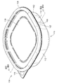
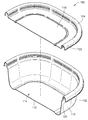
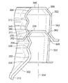
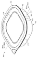
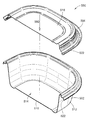
次に、図面を参照すると、図1と図2には、食物を収容し運ぶための容器100が示されている。図面では、類似の参照番号は類似の要素を指す。容器100は、底面110と、示した実施形態では底面から延在し互いに直角に配置されて正方形を構成する4つの直立側面112とを備えたベース102を有する。当然ながら、他の実施形態では、側面112の数と構成は異なってもよい。例えば、底面から円筒形の単一の側面が延在してもよいことは容易に理解されるであろう。任意の構成において、底面110と側面112は、食物を入れることができる収納部分として働く空洞114を画定するようにモールド成形によって一体形成することができる。
Referring now to the drawings, FIGS. 1 and 2 show a
空洞または収納スペース114を封止するために、容器100は、着脱可能なカバー104も有する。示した実施形態では、カバー104は、一般に、水平面116と、ベース102の四角形状に対応する四角形状とを有する平らなトレーとして形成されている。更に、カバー104は、ベース102から完全に分離可能である。しかしながら、他の実施形態では、カバー104は、ベース102の形状に対応する任意の形状を有することができ、開位置と閉位置の間で関節運動するようにベースにヒンジ式に接続されてもよい。ベース102からカバー104を分離しやすくするために、カバーは、角部から水平方向に突出する分離用タブ118を備えてもよい。
In order to seal the cavity or
ベース102とカバー104を脱着可能に結合するために、ベースとカバーは、それぞれ係合可能な第1と第2の封止部分120、122を備える。第1の封止部分120は、直立側面112によって画定されたベース102の周縁に形成されそのまわりに延在しており、第2の封止部分は、それに対応した形状でカバー104の周縁に形成されそのまわりに延在している。図1と図2によって理解されるように、第1と第2の封止部分120と122は、ベース102とカバー104を位置合わせして互いに押し付けることにより係合される。
To removably couple the
図4と図5を参照すると、第1と第2の封止部分120、122は、ベース102とカバー104の周縁に延在するU字型断面を有するスカートとして形成されている。第1の封止部分120は、直立側面112に繋がりそこからほぼ直立に延在する内側壁130を有する。また、第1の封止部分120の一部として、内側壁130から離間されその反対側にある外側壁132を有する。参照のため、用語「内側」や「外側」などは、図4と図5の基準線134を基準とし、本発明の追加の制限として解釈されるべきではない。内側壁130の上部と外側壁132の上部の間には、上向きに湾曲した中間壁136がつながり延在している。
Referring to FIGS. 4 and 5, the first and
第2の封止部分122は、第1の封止部分120と同様に形成されている。例えば、第2の封止部分122は、カバーの平坦面116に繋がりそこからほぼ直角に延在する第2の内側壁140と、その第2の内側壁140と向かい合い離間された第2の外側壁142とを有する。「内側」や「外側」などの用語の使用は、この場合も、図4と図5の基準線134を基準にして使用される。第2の内側壁140と第2の外側壁142をつなげるために、第2の封止部分122もやはり第2の上向きに湾曲した中間壁146を有する。
The
第1の封止部分120と第2の封止部分122を係合させるために、第1の封止部分は、第2の封止部分の内側壁140と外側壁142の間にはめ込まれ把持される。第1の封止部分120が第2の封止部分122にはめ込まれたとき、サイズの違いにより、第2の封止部分が第1の封止部分を締め付けるように把持することを理解するであろう。第1と第2の中間壁136、146は、内側壁と外側壁に把持力を提供し伝える弾力特性を有することができる。
To engage the
本発明の態様によれば、係合されたときに第1の封止部分120と第2の封止部分122を脱着可能に結合するために、内側壁に少なくとも1つのカットバック部分が形成される。図4と図5に示した実施形態では、第1の封止部分120の第1の内側壁130に、第1のカットバック部分150と第2のカットバック部分152が形成されている。第1と第2のカットバック部分150、152は、実質的にベース102の周縁の第1の封止部分120に沿って延在している。第1のカットバック部分150は、直立側面112から延在して第1の内向き辺(inwardly directed leg)156と交わる第1の外向き辺(outwardly directed leg)154によって形成された浅い概略V字形ノッチである。第1の外向き辺154と第1の内向き辺156の交わる部分によって、第1の外向き凹部158ができる。また、第2のカットバック部分152は、第2の外向き凹部164を作成するように交わる第2の外向き辺160と第2の内向き辺162によって形成された浅い概略V字形ノッチである。第1と第2のカットバック部分150、152は、互いに隣り合って垂直に配置され、それにより、第1の内向き辺156は、第2の外向き辺160と交わって第1の内向き凸部166を作る。更に、第2の内向き辺162は、第1の中間壁136と交差して第2の内向き凸部168を作る。
In accordance with aspects of the present invention, at least one cutback portion is formed on the inner wall to removably couple the
第2の封止部分122は、また、第3のカットバック部分170と、それと垂直方向に隣り合った第4のカットバック部分172とを有する。第3のカットバック部分170は、第3の外向き凹部178を形成するように交わる第3の外向き辺174と第3の内向き辺176によって形成された浅い概略V字形ノッチである。第4のカットバック部分172は、また、第4の外向き凹部184を形成するように交わる第4の外向き辺180と第4の内向き辺182によって形成された浅い概略V字形ノッチである。第3と第4のカットバック部分170、172は垂直方向に並べられており、その結果、第3の外向き辺174は平坦面116につながる。更に、第3の内向き辺176と第4の外向き辺180は交わって第3の内向き凸部186を作る。更に、第4の内向き辺178は第2の中間壁146と交わって第4の内向き凸部188を形成する。第3のカットバック部分170と第4のカットバック部分172間の垂直方向の距離は、第1のカットバック部分150と第2のカットバック部分152間の垂直方向の距離に対応することができる。第3と第4のカットバック部分170、172は、実質的にカバー104の周囲に延在していることを理解されよう。
The
カットバック部分は、ベースとカバーの全体寸法による任意の適切な深さ有することができる。一実施形態では、カットバック部分によって形成された概略V字形ノッチは、約0.030インチ(0.076センチ)の深さを有することができる。 The cutback portion can have any suitable depth depending on the overall dimensions of the base and cover. In one embodiment, the generally V-shaped notch formed by the cutback portion can have a depth of about 0.030 inches.
図5に示したように、第1と第2の封止部分120、122が完全に係合されたとき、第1のカットバック部分150は、第3のカットバック部分170と位置が合い当接し、第2のカットバック部分152は、第4のカットバック部分172と位置が合い当接する。以上のようにカットバック部分と位置合わせし接すると、封止部分が結合され、カバーがベースから外れにくくなることは理解されるであろう。第1と第2の封止部分120と122の係合を容易にするために、第1と第2の中間壁136、146の弾力性によって、第1の内側壁と外側壁130、132は互いに近づくように撓み、また第2の内側壁と外側壁140、142が互いから離れるように撓むことができる。従って、第1の封止部分120が第2の封止部分122に嵌め込まれたとき、内側壁と外側壁は互いに滑ってずれる。滑り込み易くするために、示した実施形態では、外側壁132、142を両方とも垂直方向にまっすぐな平坦構造で作成してもよい。カットバック部分の位置が合った後で、第1と第2の内側壁130、140は、互いに弾力的に撓んでカットバック部分を連結させる。
As shown in FIG. 5, when the first and
第1と第2の内側壁130、140のそれぞれに2つの垂直方向に隣り合ったカットバック部分150、152、170、172を有する利点は、第1と第2の封止部分120、122間の係合が強化されることである。例えば、図5から、ベース102からカバー104を取り外すには、第3と第4凹部178、184を第1と第2の凸部166、168上を滑らせるのに十分な引っ張り力を加えなければならないことを理解されよう。従って、複数のカットバック部分150、152、170、172をそれぞれ備えた第1と第2の封止部分120、122を形成すると、ベース102からカバー104を外すために加えなければならない引っ張り力が大きくなる。必要とされる力は、意図せずに外れるのを防ぐのに十分で且つ意図して外すのを難しくするほど大き過ぎないものである。
The advantage of having two vertically
内側壁130、140のそれぞれに2つのカットバック部分150、152、170、172を備えるもう1つの利点は、2倍のシール効果が提供されることである。例えば、図5を参照すると、第1と第2の封止部分が完全に係合されたとき、当接する第1と第3のカットバック部分150、170と、互いに接触する内向き辺156、176が第1のシールを作る。当接する第2と第4のカットバック部分152、172と、互いに接触する内向き辺162、182とによって、第2のシールができる。接触場所が2箇所あるので、容器内に収容された食物を保存しやすくしまた容器から漏れたりこぼたりするのを防ぐ2倍のシール効果が得られる。
Another advantage of having two
図5に示したような中間壁136、146と外側壁132、142を有するもう1つの利点は、内容物が漏れるのを防ぐのに役立つ遠回り経路を促進する連続または不連続の接触面を設けることができることである。
Another advantage of having
第1と第2の内側壁130、140のそれぞれに2つの垂直方向に隣り合ったカットバック部分150、152、170、172を有するもう1つの利点は、カットバック部分が中間係合位置を可能にすることである。例えば、図6を参照すると、第1と第4のカットバック部分150、172を係合させないまま、第2のカットバック部分152が第3のカットバック部分170と係合するように、第1の封止部分120を第2の封止部分122に嵌め込むことができる。カットバック部分のうちの2つしか係合しないことにより、シールはあまり強くなく、そのシールを容易に破ることができる。これは、容器100内の食物を電子レンジで調理するときに有利であり、その理由は、容器に圧力がかかるのを防ぐために、封止部分120、122を外して蒸気が通りやすくできるからである。
Another advantage of having two vertically
食物を更に電子レンジで調理しやすくするために、本発明の別の機能では、第1と第2の封止部分120、122に不連続部分190を形成することができる。図7と図8によく示したように、不連続部分190は、垂直方向の隣りにある第4のカットバック部分172はその状態のまま、カバー104の第3のカットバック部分170内に形成される。従って、図7に示したように、第1と第2の封止部分120、122が中間位置で係合されたとき、不連続部分190は、係合された第2と第3のカットバック部分152、170によって形成されたシールを介して空洞114から蒸気が漏れる開いたチャネルを提供する。しかしながら、図8に示したように、第1と第2の封止部分120、122が完全に係合されたとき、第2のカットバック部分152と第4のカットバック部分172は、互いに当接してベース102とカバー104の間に連続的なシールを提供する。
In order to make the food easier to cook in the microwave oven, another feature of the present invention is to form
様々な実施形態では、複数の不連続部分が、第2の封止部分に形成され、カバーの周縁に離間されてもよい。更に、第3のカットバック部分に形成された不連続部分の代わりまたは追加として、他のカットバック部分に不連続部分を形成してもよいことが理解されよう。 In various embodiments, a plurality of discontinuous portions may be formed in the second sealing portion and spaced apart at the periphery of the cover. Furthermore, it will be appreciated that discontinuities may be formed in other cutback portions in place of or in addition to the discontinuities formed in the third cutback portion.
2つの垂直方向に隣り合ったカットバック部分150、152、170、172を有する別の利点は、カットバック部分が、第1と第2の封止部分120、122が係合されたという触覚または聴覚指示を提供できることである。図4、図5および図6を参照すると、第3のカットバック部分170が滑って第2のカットバック部分152と係合したとき、ベース102とカバー104が中間的に係合されたことをユーザに示す第1の触覚および/または聴覚指示が生成されることは理解されるであろう。次に、第3のカットバック部分170が滑って第1のカットバック部分150と係合し、第4のカットバック部分172が第2のカットバック部分152と係合したとき、ベース102とカバー104が完全に係合されたことをユーザに示す第2の触覚および/または聴覚指示が生成される。
Another advantage of having two vertically
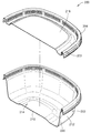
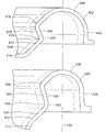
図9、図10および図11を参照すると、ベース202と着脱可能なカバー204を有する容器200の別の実施形態が示されている。ベース202は、底面210と、食物を入れることができる収納部分として機能する空洞214を画定する4つの直立側壁212とを有する。カバー204は、ベース202と係合して空洞214を密封することができる水平面216を有するほぼ平らなトレーである。ベース202とカバー204を脱着可能に結合するために、ベースとカバーはそれぞれ第1と第2の封止部分220、222を有する。第1の封止部分220は、4つの側面212の上縁によって画定されたベース202の周縁に形成されそのまわりに延在する。同じように、第2の封止部分222は、カバー204の周縁に形成されそのまわりに延在している。
Referring to FIGS. 9, 10 and 11, another embodiment of a
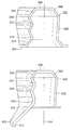
図12と図13を参照すると、第1と第2の封止部分220、222はそれぞれ、ベース202とカバー204の周縁のまわりに延在するU字型断面を有するスカートとして形成される。第1の封止部分220は、直立側面212に接合されそこからほぼ直角に延在する内側壁230を有する。また、第1の封止部分220の一部として、内側壁230から離間され対向する外側壁232を有する。内側壁230と外側壁232の間には、それらを相互接続する上方に湾曲した中間壁236がある。参照のため、用語「内側」や「外側」などは、図12と図13の基準線234を基準としており、本発明の更なる限定として解釈されるべきではない。第2の封止部分222は、また、カバー202の水平面216から延在する内側壁240と、それと離間した、上方に湾曲した中間壁246によって内側壁に相互接続された外側壁242とを有するU字型スカートとして形成される。
Referring to FIGS. 12 and 13, the first and
第1の封止部分220が第2の封止部分222にはめ込まれたとき、そのサイズの違いによって、第1と第2の封止部分を係合させる圧縮的な把持力がかかることは理解されるであろう。
When the
係合されたときに第1と第2の封止部分220、222を脱着可能に連結できるようにするために、両方の封止部分の内側壁230、240は、1つまたは複数のカットバック部分を有する。例えば、第1の封止部分220の内側壁230は、第1のカットバック部分250と、これと垂直方向に隣り合った第2のカットバック部分252とを有する。同様に、第2の封止部分222の内側壁240は、第3のカットバック部分270と、これと垂直方向に隣り合った第4のカットバック部分272を有する。カットバック部分250、252、270、272は、以上述べたように形成し係合することができる。従って、2倍のカットバック部分250、252、270、272は、2倍のシール効果と、2倍の係合触覚および/または聴覚指示を提供する。例えば、図13を参照すると、第1と第2の封止部分が完全に係合されたとき、第1と第3のカットバック部分250、270の上にある内向き辺の間の接触によって第1のシールが作成される。第2のシールは、カットバック部分252、272の上にあって互いに接触する内向き辺の間の接触によって作成される。接触位置が2箇所あるため、容器に収容された食物の保存を容易にし且つ容器から漏れたりこぼれたりするのを防ぐ2倍のシール効果が得られる。
In order to allow the first and
図13に示したような中間壁236、246と外側壁232、242を有することの別の利点は、内容が漏れるのを防ぐ遠回り経路を促進する連続または不連続接触面を設けることができることである。
Another advantage of having
更に、カットバック部分250、252、270、272は、ベース202またはカバー204を、図13に示したような完全係合位置または図14に示したような中間位置で結合させることを可能にする。
Further, the
係合された封止部分220、222間の把持力を更に高めるために、図12と図13に示した実施形態では、第2の封止部分の外側壁242が、内側壁240の方に少し傾いた角度で形成される。例えば、外側壁242は、中間壁246から下方で内側壁240と基準線234の方に少し傾いて延在する第1の傾斜辺280を有する。外側壁は、また、外方に突出する第1の段282と、内側壁240と基準線234の方に少し傾いて延在する第2の傾斜辺284とを有する。第2の傾斜辺284の下縁から外方に、外向きフランジ286が延在している。第1の封止部分220の外側壁232は、また、場所が第1の段282に対応する第2の外方に突出する段288を有する。従って、図13において、第1と第2の封止部分220、222が完全に係合されたとき、第1の傾斜辺280が第1の外側壁232を押し、第1の段282は第2の段288のまわりを滑り、その結果第2の傾斜辺284が第2の段にぶつかる。更に、図14において、第1と第2の封止部分220、222が中間係合されたとき、外向きフランジ286は第2の段288の上に当たる。
In order to further increase the gripping force between the engaged sealing
図15、図16および図17を参照すると、ベース302と着脱可能なカバー304を有する容器300の別の実施形態が示されている。ベース302は、底面310と、食物を入れることができる収納部分としての機能する空洞314を画定する4つの直立側壁312とを有する。カバー304は、ベース302と係合して空洞314を封止することができる水平面316を有するほぼ平らなトレーである。ベース302とカバー304を解除可能に結合するために、ベースとカバーはそれぞれ、第1と第2の封止部分320、322を有する。第1の封止部分320は、4つの側面312の上縁によって画定されたベース302の周縁に形成されそのまわりに延在している。同じように、第2の封止部分322は、カバー304の周縁に形成されそのまわりに延在している。
With reference to FIGS. 15, 16 and 17, another embodiment of a
図18と図19を参照すると、第1と第2の封止部分320、322は両方とも、それぞれのベース302とカバー304の周縁のまわりに延在するU字型スカートとして形成される。第1の封止部分320は、直立側壁312から垂直方向に延在する内側壁330と、離間された外側壁332とを有する。前述のように、用語「内側」と「外側」は、基準線334を基準にしている。内側壁330と外側壁332は、中間壁336によってつながっている。第1の封止部分320と同じように、第2の封止部分322も、中間壁346によって相互接続された内側壁340とそれと離間した外側壁342とを有する。第1と第2の封止部分320、322を係合させるために、第1の封止部分は、第2の封止部分の内側壁と外側壁340、342の間にはめ込まれ、第2の封止部分によって圧縮的に把持される。
With reference to FIGS. 18 and 19, both the first and
係合されたときに第1と第2の封止部分320、322が解除可能に連結できるように、両方の封止部分の内側壁330、340は、1つまたは複数のカットバック部分を有する。例えば、第1の封止部分320の内側壁330は、第1のカットバック部分350と垂直方向に隣り合った第2のカットバック部分352とを有する。同様に、第2の封止部分322の内側壁340は、第3のカットバック部分370と垂直方向に隣り合った第4のカットバック部分372とを有する。カットバック部分350、352、370、372は、前述のように形成し係合させることができる。従って、2倍のカットバック部分350、352、370、372は、2倍のシール効果と、2倍の係合触覚および/または聴覚指示を提供する。例えば、図19を参照すると、第1と第2のカットバック部分350、370の上にある内向き辺の間の接触によって第1のシールができる。同様に、第3と第4のカットバック部分352、372の上にある内向き辺の間の接触によって第2のシールができる。接点位置が2箇所あるため、容器に収容された食物の保存を容易にし容器から漏れたりこぼれたりするのを防ぐ2倍のシール効果が得られる。
The
更に、カットバック部分350、352、370、372は、ベース302とカバー304を、図19に示したような完全係合位置または図6と図14に示した位置と同じ中間位置で結合することを可能にする。
Further, the
図18と図19の実施形態に示したような本発明の別の態様では、ベース302とカバー304の積み重ねを容易にするために、第1と第2の封止部分320、322は、内側壁および外側壁のそれぞれと中間壁との間に形成された肩部を有することができる。例えば、第1の封止部分320の垂直方向の内側壁330は、内側壁と中間壁の間で約45度の角度で傾斜する第1の肩部380によって、水平方向の中間壁336につながっている。同じように、垂直方向の外側壁332と中間壁336は、傾斜した第2の肩部382によってつながっている。カバー304上の第2の封止部分322を参照すると、垂直方向の内側壁と外側壁330、332も、傾斜した第3と第4の肩部384、386によってそれぞれ水平方向の中間壁336につながっている。
In another aspect of the invention as shown in the embodiment of FIGS. 18 and 19, the first and
肩部と動作可能に係合するために、それぞれの第1と第3のカットバック部分350、370の第1と第3の内向き辺354、374は、約45度の角度で傾けられている。更に、第2の外側壁342の下縁には、約45度の角度で外方に傾いた辺388が形成されている。
In order to operably engage the shoulder, the first and third
図20を参照すると、ベース302と蓋304は、積み重ね用肩部が、積み重ね式または組み立て式で動作可能に係合された状態で配置されている。例えば、第2の封止部分322は、第3のカットバック部分370の第3の内向き辺374が第1の肩部部分380と接触するように第1の封止部分320の上にセットすることができる。更に、第2の外側壁342の傾斜辺388は、第2の肩部部分382と接触する。従って、第2の封止部分322は、(1)第1の肩部380と第3の内向き辺370の係合部と(2)第2の肩部382と傾斜辺388の係合部との2つの別個の接触部分で、第1の封止部分320の上に安定して支持される。更に、第1と第2の肩部380と382を、それぞれの第3の内向き辺370と傾斜辺388と約45度の傾斜面に沿って係合させることにより、水平方向と垂直方向の両方の力に抗する入れ子効果が提供されることは理解されよう。従って、積み重ねられたときにベース302とカバー304が横方向の力によって意図せずにずれるのが防止される。ベースとカバーを積み重ねるか組み立てることにより、容器を戸棚にきちんと収納し易くなる。更に、当業者は、肩部により、複数のカバーを積み重ねたり、複数のベースを積み重ねたりすることも可能になることを理解するであろう。
Referring to FIG. 20, the
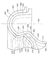
図21、図22および図23を参照すると、ベース402と着脱可能なカバー404を有する容器400の別の実施形態が示されている。説明的なベース402は、食物を入れることができる空洞414を画定する水平の底面410と4つの直立部材側面412とを有する。カバー404は、ベース402と係合して空洞414を封止することができる水平面416を有するほぼ平らなトレーである。ベース402とカバー404を脱着可能に結合するために、ベースとカバーはそれぞれ、第1と第2の封止部分420、422を備える。第1の封止部分420は、4つの側面412の上縁によって画定されたベース402の周縁に形成されそのまわりに延在している。同様に、第2の封止部分422が、カバー404の周縁に形成されそのまわりに延在している。
Referring to FIGS. 21, 22, and 23, another embodiment of a
図24と図25を参照すると、第1と第2の封止部分420、422は両方とも、それぞれのベース402とカバー404の周縁に延在するU字型スカートとして形成される。第1の封止部分420は、直立側壁412から垂直方向に延在する内側壁430と、それと離間した外側壁432とを有する。この場合も、用語「内側」と「外側」は、基準線434を基準とする。内側壁430と外側壁432は、上向きに湾曲した中間壁436によってつながっている。第1の封止部分420と同じように、第2の封止部分422も、中間壁446によって相互接続された内側壁440とそれと離間した外側壁442とを有する。
Referring to FIGS. 24 and 25, the first and
第1と第2の封止部分420、422を係合させるために、第1の封止部分は、第2の封止部分の内側壁440と外側壁442の間にはめ込まれ把持される。第1の封止部分420が、第2の封止部分422にはめ込まれたとき、サイズの違いにより、第2の封止部分が第1の封止部分を締め付けるように把持することは理解されよう。第1と第2の中間壁436、446は、内側壁と外側壁に把持力を提供し伝える弾力特性を有することができる。
To engage the first and
係合されたときに第1と第2の封止部分420、422を解除可能に連結するために、第1と第2の内側壁430、440はそれぞれ、第1と第2のカットバック部分450、470を有する。第1のカットバック部分450は、湾曲した中間壁436から延在する第1の内向き辺454と交わる直立側面412から延在している第1の外向き辺452によって形成された浅い概略V字形ノッチとして形成される。第1と第2の辺452、454の交わる部分には外向き凹部456が作成される。更に、第2の辺454と中間壁436の交わる部分に内向き凸部458が作成される。同様に、第2のカットバック部分470は、第2の外向き凹部476を提供するように交わる第2の外向き辺472と第2の内向き辺474によって形成された概略V字形ノッチとして形成される。また、第2の内向き辺474は、中間壁436と交わって内向き凸部478を作成する。
In order to releasably connect the first and
第1と第2の封止部分が完全係合位置にあるとき、図25に示したように、第1と第2のカットバック部分は互いに位置が合い当接する。前述のようにカットバック部分が位置合わせされ隣接されたとき、封止部分が連結され、カバーがベースから外れにくくなることは理解されるであろう。封止部分の係合を容易にするために、中間壁436、446は、第1の封止部分を第2の封止部分にはめ込む際に内側壁430、440と外側壁432、442がずれるのを可能にする柔軟で弾力的な特性を有することができる。柔軟で弾力的な特性は、封止部分を保持する圧縮把持力を提供する。
When the first and second sealing portions are in the fully engaged position, as shown in FIG. 25, the first and second cutback portions are positioned and abutted against each other. It will be appreciated that when the cutback portions are aligned and adjacent as described above, the sealing portions are connected and the cover is less likely to come off the base. In order to facilitate engagement of the sealing portions, the
この実施形態の封止部分420、422を前述のように設計することにより、例えばカバーの中心を下方に押すことにより係合できるようにすることによって、ベース402とカバー404の取り付けが簡単になる。例えば、図21と図23を参照すると、カバー404の平らな水平面416には、係合力が封止部分420、422の方に外側に広がるのを妨げる障害物がない。更に、ベース402とカバー404の角部は、丸くされるか曲げられている。丸い角部は尖った角部よりも密封力が封止部分に均一に分散しやすくなることは理解されよう。他の実施形態では、ベースとカバーを円形に形成することによってこの効果の利点を更に活用することができる。
By designing the sealing
封止部分420、422において、図24と図25に示したように、第2の封止部分470の傾斜した第2の内向き辺472は、はめ込む際に、第2の封止部分422の第2の内側壁440と第2の外側壁442の間で第1の封止部分420をガイドする働きをすることが分かる。更に、第2の外側壁442は、第1の中間壁436の湾曲した半円形の形状によって滑るように外方に導かれる。内側壁と外側壁を前述のようにガイドすることにより、封止部分を係合させるのに必要な係合力または密封力に対する抵抗が小さくなる。更に、内側壁430、440のそれぞれに1つのカットバック部分450、470しか設けられないので、封止部分420、422と係合するのに必要な力が小さくなる。最後に、第1と第2の外側壁432、442が、滑らかで垂直方向に真っ直ぐな構造なので、外側壁は、はめ込む際に互いに滑り易い。従って、ベース402とカバー404は、カバーの中心を単純に押すことによって完全に係合させることができる。また、内側壁のそれぞれに単一のカットバック部分を設けることによって、封止部分420、422が係合されたときに聴覚および/または触覚指示が1回しか提供されないことを理解されたい。例えば、図25を参照すると、内向き辺454、474の間の接触によってシールが作成される。この接触位置により、容器に収容された食物を保存しやすくし且つ容器から漏れたりこぼれたりするのを防ぐシール効果が向上する。
In the sealing
図25に示したような中間壁436、446と外側壁432、442を有する別の利点は、内容物が漏れるのを防ぐのに役立つ遠回り経路を促進する連続または不連続な接触面を提供できることである。
Another advantage of having
図26、図27および図28を参照すると、ベース502と着脱可能なカバー504を有する容器500の別の実施形態が示されている。説明のためのベース502は、食物を入れることができる空洞514を画定する水平な底面510と4つの直立側面512とを有する。空洞514に上部空間を提供するために、カバー504は、下方に延在するスカート518によって支持されたほぼ水平な上面516を有するシェルである。当然ながら、他の実施形態では、上面516とスカート518を有するカバー504は、他の適切な形状を有することができる。空洞514を密封するために、カバー504はベース502と係合することができる。ベース502からカバー504を分離し易くするために、カバーの角部から突出する分離用タブ519を設けることができる。ベース502とカバー504を解除可能に連結するために、ベースとカバーは、それぞれの第1と第2の封止部分520、522を有する。第1の封止部分520は、4つの側面512の上縁によって画定されたベース502の周縁に形成されそのまわりに延在する。第2の封止部分522は、下向きのスカート518の最下縁に形成されそのまわりに延在している。
26, 27 and 28, another embodiment of a
図29と図30を参照すると、第1の封止部分520は、直立側面512につながったシール部分530と、一体形成された外向きフランジ540とを有する。同様に、第2の封止部分522は、下向きのスカート518につながった第2のシール部分550と、一体的で外向きの第2のフランジ560とを有する。
Referring to FIGS. 29 and 30, the
第1と第2の封止部分520、522を連結し封止するために、第1のシール面530は、直立側面512から延在する水平方向の縁または辺532と、水平方向の辺の端部に形成された外方に突出する凸部534とを有する。凸部534にはそのほぼ下に、第1のほぼ湾曲した第1のカットバック部分536がつながっている。第2のシール部分550は、また、下向きスカート518から延在する第2の水平方向の縁または辺552と、第2の水平方向の辺のほぼ下にある第2のカットバック部分554とを有する。第1と第2の封止部分520、522が共に押されたとき、第2のカットバック部分554は、凸部534を通り過ぎて、第1のカットバック部分536と位置が合い当接する。当業者によって理解されるように、カットバック部分を前述のように位置合わせし隣接させると、封止部分が連結され、ベースからカバーが外れにくくなる。更に、図28に示したように、第1と第2のカットバック部分536、554がこのように隣接されたとき、第1の水平な辺532と第2の水平な辺552が互いに接触して、空洞514を漏れないようにシールする。
In order to connect and seal the first and
更に、各封止部分に1つのカットバック部分しかないので、封止部分と係合するのに必要な力が実質的に小さくなる。図27を参照すると、カバー502の水平面516の中心に単純な下方の力を加えるか押すことによって(矢印580で示した)、第1と第2の封止部分520、522を係合させることができる。また、内側壁のそれぞれに単一のカットバック部分を設けることによって、封止部分520、522が係合されたときに聴覚および/または触覚指示が1回しか提供されないことを理解されたい。
Furthermore, since each sealing portion has only one cutback portion, the force required to engage the sealing portion is substantially reduced. Referring to FIG. 27, engaging the first and
図29と図30に示した第1と第2のフランジ540、560を再び参照すると、各フランジは、それぞれの第1と第2のカットバック部分536、554から外方に延在するそれぞれの第3と第4の水平な辺542、562を有する。更に、各フランジ540、560は、第3と第4の水平な辺542、562から続く第1と第2の反った辺544、564をそれぞれ有する。第1と第2の封止部分520、522を係合させたとき、第1と第2の水平な辺542、562は互いに接触して封止力を高め、第1と第2の分岐する辺544、564が互いから離れて分岐する。図29と図30から分かるように、ユーザは、第1と第2の分岐する辺544、564の間に指を入れて辺を掴んで逆方向に引っ張ることにより、ベース502とカバー504を開けることができる。従って、この実施形態は、図26に示した分離用タブ519がない場合でも容器を簡単に開けることができる。
Referring again to the first and
前述の実施形態のいずれの容器も、例えば透明なポリプロピレンホモポリマを含む任意の適切な材料で作成することができる。更に、容器は、透明なランダムコポリマポリプロピレン素材から作成することができる。容器を製造するのに適した他の材料には、PS(ポリスチレン)、CPET(結晶ポリエチレンテレフタレート)、APET(非晶質ポリエチレンテレフタレート)、LDPE(低密度ポリエチレン)、HDPE(高密度ポリエチレン)、PVC(ポリ塩化ビニル)、PC(ポリカーボネート)および発泡ポリプロピレンがある。 Any container of the foregoing embodiments can be made of any suitable material including, for example, a clear polypropylene homopolymer. Further, the container can be made from a transparent random copolymer polypropylene material. Other materials suitable for manufacturing the container include PS (polystyrene), CPET (crystalline polyethylene terephthalate), APET (amorphous polyethylene terephthalate), LDPE (low density polyethylene), HDPE (high density polyethylene), PVC (Polyvinyl chloride), PC (polycarbonate) and expanded polypropylene.
容器の材料は、容器の内容物を見ることができるように透明か半透明でよく、様々な実施形態では、容器は、第1と第2の封止部分が適切に係合されてシールされていることを示す視覚的指示を備えてもよい。例えば、視覚的指示は、第1と第2の封止部分が係合されたとき第3の色を生成する第1の封止部分上の第1の色と第2の封止部分上の第2の色を塗布することによって提供することができる。 The container material may be transparent or translucent so that the contents of the container can be seen, and in various embodiments, the container is sealed with the first and second sealing portions properly engaged. A visual indication may be provided. For example, the visual indication may be that the first color on the first sealing portion and the second sealing portion generate a third color when the first and second sealing portions are engaged. It can be provided by applying a second color.
容器は、例えば熱成形、射出成形、真空成形を含む任意の適切な方法で製造することができる。更に、容器は、容器を区分するために空洞を分割する1つまたは複数の一体形成された区分室を含むように製造されてもよい。 The container can be manufactured by any suitable method including, for example, thermoforming, injection molding, vacuum forming. Further, the container may be manufactured to include one or more integrally formed compartments that divide the cavity to divide the container.
容器のベースとカバーは、前述のどのタイプの材料シートからも製造することができる。以上の特徴により、容器は、1回使用するもの、使い捨てのもの、または何度も再使用しやすいものと考えることができる。 The base and cover of the container can be made from any of the aforementioned types of material sheets. Due to the above characteristics, the container can be considered to be used once, disposable, or easily reused many times.
本明細書で引用した出版物、特許出願および特許を含むすべての参考文献は、それぞれの参照文献が、参照により組み込まれるように個別に具体的に示され、全体が本明細書で説明されたのと同じように参照により本明細書に組み込まれる。 All references, including publications, patent applications, and patents cited herein, are individually and specifically shown with each reference incorporated by reference, and are described herein in their entirety. As is incorporated herein by reference.
本発明を説明する文脈(特に、特許請求の範囲の文脈)における用語の使用は、本明細書で特に示すか文脈によって明らかに否定されない限り、単数と複数の両方を対象として含むように解釈されるべきである。用語「成る」、「もつ」、「含む」および「有する」は、特に断らない限り、オープンエンドの用語(即ち、「含むが限定されない」の意味)として解釈されるべきである。本明細書における値の範囲の列挙は、本明細書で特に示さない限り、範囲内にあるそれぞれの別の値を個々に参照する簡略的な方法として役立つように意図されており、それぞれの別の値は、本明細書で個々に引用されたかのように本明細書に組み込まれる。本明細書で述べたすべての方法は、本明細書に特に示さないかまたは文脈によって明らかに否定しない限り、任意の適切な順序で実行することができる。本明細書に提供される任意およびすべての例、または例示的言語の使用は、単に本発明をよりよく解明するように意図されており、特に請求しない限り本発明の範囲を限定しない。本明細書内の言語は、本発明の実施に不可欠なものとしていかなる非請求要素も示すように解釈されるべきでない。 The use of terms in the context of describing the present invention (especially in the context of the claims) is to be interpreted to include both the singular and the plural unless specifically indicated herein or otherwise clearly contradicted by context. Should be. The terms “consisting”, “having”, “including” and “having” are to be interpreted as open-ended terms (ie, meaning “including but not limited to”), unless otherwise specified. The recitation of value ranges herein is intended to serve as a concise way of referring individually to each other value within the range, unless specifically stated otherwise herein. The values of are incorporated herein as if individually cited herein. All methods described herein can be performed in any suitable order unless otherwise indicated herein or otherwise clearly contradicted by context. The use of any and all examples or exemplary languages provided herein are merely intended to better elucidate the invention and do not limit the scope of the invention unless specifically claimed. No language in the specification should be construed as indicating any non-claimed element as essential to the practice of the invention.
本明細書において、本発明を実施するために発明者に知られている最良の形態を含む本発明の好ましい実施形態が説明される。そのような好ましい実施形態の変形例は、以上の説明を読むことにより当業者に明らかになる。発明者は、当業者がそのような変形例を適切に使用することを期待し、また発明者は、本明細書に具体的に示された以外の方法で本発明を実施することを意図する。従って、本発明は、準拠法によって許可されるように添付された特許請求の範囲内で列挙された内容のすべての修正物と均等物を含む。更に、すべての可能な変形例における前述の要素の任意の組み合わせは、本明細書に特に示されず文脈によって明確に否定されない限り、本発明に含まれる。 Preferred embodiments of this invention are described herein, including the best mode known to the inventors for carrying out the invention. Variations of such preferred embodiments will become apparent to those of ordinary skill in the art upon reading the foregoing description. The inventor expects those skilled in the art to properly use such variations, and the inventor intends to practice the invention in ways other than those specifically set forth herein. . Accordingly, this invention includes all modifications and equivalents of the subject matter recited in the claims appended hereto as permitted by applicable law. Moreover, any combination of the above-described elements in all possible variations thereof is encompassed by the invention unless otherwise indicated herein and otherwise clearly contradicted by context.
102 ベース
104 カバー
120 第1の封止部分
122 第2の封止部分
130 第1の内側壁
132 第1の外側壁
136 第1の中間壁
140 第1の内側壁
142 第2の外側壁
146 第2の中間壁
150 第1のカットバック部分
152 第2のカットバック部分
154 第1の外向き辺
156 第1の内向き辺
158 第1の外向き凹部
160 第2の外向き辺
162 第2の内向き辺
164 第2の外向き凹部
166 第1の内向き凸部
168 第2の内向き凸部
170 第3のカットバック部分
172 第4のカットバック部分
174 第3の外向き辺
176 第3の内向き辺
178 第3の外向き凹部
180 第4の外向き辺
182 第4の内向き辺
184 第4の外向き凹部
186 第3の内向き凸部
188 第4の内向き凸部
102
Claims (20)
内側壁およびそれと離間した外側壁を備えた第1の封止部分を有するベースであって、内側壁が第1のカットバック部分と第2のカットバック部分とを有するベースと、
カバーであって、カバーをベースに脱着可能に結合するために第1の封止部分と係合可能な第2の封止部分を有するカバーとを備えた容器。 A container,
A base having a first sealing portion with an inner wall and an outer wall spaced therefrom, wherein the inner wall has a first cutback portion and a second cutback portion;
A cover comprising a cover having a second sealing portion engageable with the first sealing portion for releasably coupling the cover to the base.
第1の封止部分を有するベースであって、第1の封止部分が内側壁およびそれと離間された外側壁を有し、内側壁が第1のカットバック部分を有し、外側壁がほぼ垂直方向に平坦であるベースと、
第2の封止部分を有するカバーであって、第2の封止部分が内側壁およびそれと離間された外側壁を有し、内側壁が第2のカットバック部分を有し、外側壁がほぼ垂直方向に平坦であるカバーとを有する容器。 A container,
A base having a first sealing portion, wherein the first sealing portion has an inner wall and an outer wall spaced apart from the inner wall, the inner wall has a first cutback portion, and the outer wall is approximately A base that is flat in the vertical direction;
A cover having a second sealing portion, wherein the second sealing portion has an inner wall and an outer wall spaced apart from the inner wall, the inner wall has a second cutback portion, and the outer wall is approximately A container having a cover that is flat in the vertical direction.
第1の封止部分を有するベースであって、第1の封止部分が、第1のシール部分と、第2のシール部分から外方に向けられた第1のフランジとを備えたベースと、
第2の封止部分を有するカバーであって、第2の封止部分が、第2のシール部分と、第2のシール部分から外方に向けられた第2のフランジとを備えたカバーとを備え、
第1と第2のフランジは、第1と第2の封止部分が係合されたときに互いから部分的に離れるように適応された容器。 A container,
A base having a first sealing portion, wherein the first sealing portion comprises a first sealing portion and a first flange directed outwardly from the second sealing portion; ,
A cover having a second sealing portion, wherein the second sealing portion includes a second sealing portion and a second flange directed outwardly from the second sealing portion; With
The container wherein the first and second flanges are adapted to be partially separated from each other when the first and second sealing portions are engaged.
Applications Claiming Priority (2)
| Application Number | Priority Date | Filing Date | Title |
|---|---|---|---|
| US11/064,868 US8157123B2 (en) | 2005-02-23 | 2005-02-23 | Container |
| PCT/US2006/005491 WO2006091471A2 (en) | 2005-02-23 | 2006-02-16 | Container |
Publications (2)
| Publication Number | Publication Date |
|---|---|
| JP2008531412A true JP2008531412A (en) | 2008-08-14 |
| JP2008531412A5 JP2008531412A5 (en) | 2009-04-02 |
Family
ID=36927910
Family Applications (1)
| Application Number | Title | Priority Date | Filing Date |
|---|---|---|---|
| JP2007557061A Ceased JP2008531412A (en) | 2005-02-23 | 2006-02-16 | container |
Country Status (14)
| Country | Link |
|---|---|
| US (2) | US8157123B2 (en) |
| EP (1) | EP1851133B1 (en) |
| JP (1) | JP2008531412A (en) |
| KR (1) | KR20070108876A (en) |
| CN (1) | CN101128364B (en) |
| AU (1) | AU2006216890B2 (en) |
| CA (1) | CA2596218C (en) |
| DE (1) | DE602006021279D1 (en) |
| ES (1) | ES2363987T3 (en) |
| HK (1) | HK1114591A1 (en) |
| MX (1) | MX2007010252A (en) |
| NZ (1) | NZ560382A (en) |
| WO (1) | WO2006091471A2 (en) |
| ZA (1) | ZA200706450B (en) |
Cited By (6)
| Publication number | Priority date | Publication date | Assignee | Title |
|---|---|---|---|---|
| JP2013075915A (en) * | 2005-09-16 | 2013-04-25 | Cornell Research Foundation Inc | Method for decreasing expression of cd36 |
| JP2013530888A (en) * | 2010-05-27 | 2013-08-01 | ボカ エンタープライズ グループ,インコーポレーテッド | Container lid |
| JP2014201313A (en) * | 2013-04-01 | 2014-10-27 | 電気化学工業株式会社 | Packaging container |
| JP2016185826A (en) * | 2013-07-19 | 2016-10-27 | エス.シー. ジョンソン アンド サン、インコーポレイテッド | Storage container system |
| US9624011B2 (en) | 2014-03-05 | 2017-04-18 | uVu Technologies, LLC | Lid with rotatable closure tab |
| JP2022538966A (en) * | 2019-07-05 | 2022-09-07 | エス.シー. ジョンソン アンド サン、インコーポレイテッド | A storage container system including a container and corresponding lid |
Families Citing this family (75)
| Publication number | Priority date | Publication date | Assignee | Title |
|---|---|---|---|---|
| US8074831B2 (en) * | 2004-04-15 | 2011-12-13 | Berry Plastics Corporation | Drink cup and lid |
| US7866502B2 (en) * | 2005-06-21 | 2011-01-11 | The Glad Products Company | Venting container |
| US20090084796A1 (en) * | 2006-01-18 | 2009-04-02 | Coonce Ryan J | Containers with interlocking covers |
| US20110089187A1 (en) * | 2006-08-10 | 2011-04-21 | Capitol Vial Inc. | Shatterproof Container And Cap Assembly |
| US8083094B2 (en) * | 2006-08-10 | 2011-12-27 | Capitol Vial Inc. | Container and cap assembly |
| KR101308349B1 (en) | 2006-11-15 | 2013-09-17 | 히타치가세이가부시끼가이샤 | Process for producing heat curable resin composition for light reflection |
| WO2009089389A1 (en) * | 2008-01-08 | 2009-07-16 | Clear Lam Packaging, Inc. | Tamper evident container |
| US8083095B2 (en) * | 2008-06-27 | 2011-12-27 | Shye Worldwide, LLC, (CA Ltd Liability Co.) | Container assembly having positive snap seal |
| US8484888B2 (en) * | 2009-01-26 | 2013-07-16 | Amba Technologies, Llc | Landscape soil and water retention device |
| US8875927B2 (en) * | 2009-09-23 | 2014-11-04 | Anchor Packaging, Inc. | Container with self-venting features |
| US20110114638A1 (en) * | 2009-11-16 | 2011-05-19 | Kettner Catherine E | Lid for containers and methods |
| US8074830B2 (en) | 2010-03-04 | 2011-12-13 | Maple Leaf Foods Inc. | Reclosable container and closure therefor |
| US8322558B2 (en) * | 2010-05-18 | 2012-12-04 | Edward A Andrews | Free-standing, stackable cereal bowl with elevated trough |
| US9340330B2 (en) | 2010-06-24 | 2016-05-17 | S. C. Johnson & Son, Inc. | Storage container lids |
| US20110315566A1 (en) * | 2010-06-29 | 2011-12-29 | Clever Girl Concepts, LLC | Customizable storage container system |
| CA2804720C (en) * | 2010-07-16 | 2018-05-01 | Cascades Canada Ulc | Plastic container |
| DE102011000392B4 (en) * | 2011-01-28 | 2014-02-06 | Emsa Gmbh | Aufbewahrungsbehälterset |
| US9034231B2 (en) | 2011-04-14 | 2015-05-19 | Berry Plastics Corporation | Cup lid |
| US8863975B2 (en) * | 2011-12-02 | 2014-10-21 | Rehrig Pacific Company | Waste container |
| TWM433375U (en) * | 2012-01-06 | 2012-07-11 | Ya-Qian Zheng | Double seal structure for both inside and outside of rectangular food container |
| TWM434753U (en) * | 2012-01-06 | 2012-08-01 | Ya-Qian Zheng | Inside-outside double seal assembly structure for round food container |
| US9340334B2 (en) | 2012-03-09 | 2016-05-17 | Fit & Fresh, Inc. | Sealable container for household use |
| US8727620B2 (en) * | 2012-09-28 | 2014-05-20 | S.C. Johnson & Son, Inc. | Storage bag with dimple features |
| US9364107B2 (en) | 2013-03-15 | 2016-06-14 | Berry Plastics Corporation | Drink cup lid |
| USD720178S1 (en) | 2013-07-19 | 2014-12-30 | S.C. Johnson & Son, Inc. | Container |
| USD719399S1 (en) | 2013-07-19 | 2014-12-16 | S. C. Johnson & Son, Inc. | Container |
| USD742743S1 (en) | 2013-10-10 | 2015-11-10 | S.C. Johnson & Son, Inc. | Container |
| USD721246S1 (en) | 2013-07-19 | 2015-01-20 | S. C. Johnson & Son, Inc. | Container |
| USD742224S1 (en) | 2013-07-19 | 2015-11-03 | S.C. Johnson & Son, Inc. | Container |
| USD760073S1 (en) | 2014-03-13 | 2016-06-28 | S.C. Johnson & Son, Inc. | Container |
| USD723864S1 (en) | 2013-07-19 | 2015-03-10 | S.C. Johnson & Son, Inc. | Container |
| USD741171S1 (en) | 2013-07-19 | 2015-10-20 | S.C. Johnson & Son, Inc. | Container |
| USD752973S1 (en) | 2013-07-19 | 2016-04-05 | S. C. Johnson & Son, Inc. | Container |
| USD725433S1 (en) | 2013-07-19 | 2015-03-31 | S.C. Johnson & Son, Inc. | Container |
| USD741708S1 (en) | 2013-10-10 | 2015-10-27 | S.C. Johnson & Son, Inc. | Container |
| USD744336S1 (en) | 2013-07-19 | 2015-12-01 | S.C. Johnson & Son, Inc. | Container lid |
| USD741170S1 (en) | 2013-07-19 | 2015-10-20 | S.C. Johnson & Son, Inc. | Container |
| USD724891S1 (en) | 2013-07-19 | 2015-03-24 | S.C. Johnson & Son, Inc. | Container |
| USD712703S1 (en) | 2013-09-06 | 2014-09-09 | Kraft Foods Group Brands Llc | Container for food product |
| USD744294S1 (en) * | 2013-10-01 | 2015-12-01 | Jacqueline Linder | Container |
| USD744295S1 (en) * | 2013-10-01 | 2015-12-01 | Jacqueline Linder | Container |
| EP3085635A4 (en) * | 2013-12-18 | 2017-07-26 | Toyo Seikan Co., Ltd. | Molded lid and method for fitting said lid onto container, and sealing method |
| USD759478S1 (en) * | 2014-06-04 | 2016-06-21 | Peninsula Packaging, Llc | Container |
| US9814334B2 (en) | 2014-10-24 | 2017-11-14 | Berry Plastics Corporation | Drink cup lid |
| US9371153B1 (en) * | 2015-03-04 | 2016-06-21 | Modern Twist, Inc. | Shaped elastomeric container with integrated leak resistant seal |
| USD781703S1 (en) | 2015-09-02 | 2017-03-21 | First Quality Packaging Solutions, Llc | Cup lid |
| USD770279S1 (en) | 2015-09-02 | 2016-11-01 | First Quality Packaging Solutions, Llc | Cup lid |
| USD782303S1 (en) | 2015-09-02 | 2017-03-28 | First Quality Packaging Solutions, Llc | Cup lid |
| USD819407S1 (en) * | 2015-10-28 | 2018-06-05 | Lourdes Hutchinson | Tray with lid |
| USD795015S1 (en) * | 2016-03-07 | 2017-08-22 | Alexander Segal | Food container including base and lid |
| USD795057S1 (en) * | 2016-03-08 | 2017-08-22 | Alexander Segal | Food container |
| EP3426737B1 (en) * | 2016-03-08 | 2021-11-24 | 3D Systems, Incorporated | Non-isocyanate polyurethane inks for 3d printing |
| CN108128539A (en) * | 2016-12-01 | 2018-06-08 | 曹文岭 | A kind of sealing container with staggeredly fin |
| USD808794S1 (en) * | 2016-12-13 | 2018-01-30 | Dart Industries Inc. | Storage container |
| JP6355707B2 (en) * | 2016-12-22 | 2018-07-11 | シーピー化成株式会社 | Packaging container |
| US10577159B2 (en) | 2017-04-07 | 2020-03-03 | Berry Plastics Corporation | Drink cup lid |
| ES2951634T3 (en) | 2017-08-07 | 2023-10-24 | Berry Global Inc | Method and apparatus for thermoforming an article |
| USD895420S1 (en) * | 2018-07-16 | 2020-09-08 | Taishan Changjiang Plastic Product Co., Ltd | Container |
| USD907997S1 (en) | 2018-08-10 | 2021-01-19 | Berry Global, Inc. | Drink cup lid |
| US10625906B1 (en) * | 2018-11-16 | 2020-04-21 | Stasher, Inc. | Inside out method of manufacturing a container with a leak resistant seal |
| USD903483S1 (en) | 2018-11-16 | 2020-12-01 | Stasher, Inc. | Sealable container |
| US10407217B1 (en) | 2018-11-16 | 2019-09-10 | Stasher, Inc. | Method of manufacturing a container with a leak resistant seal |
| WO2020163461A1 (en) | 2019-02-06 | 2020-08-13 | Berry Global, Inc. | Polypropylene sheets and articles |
| US11433591B2 (en) | 2019-02-06 | 2022-09-06 | Berry Global, Inc. | Process of forming polymeric material |
| USD911168S1 (en) | 2019-03-05 | 2021-02-23 | Berry Global, Inc. | Drink cup lid |
| USD955874S1 (en) | 2019-12-20 | 2022-06-28 | S. C. Johnson & Son, Inc. | Container |
| US11873143B2 (en) | 2020-02-06 | 2024-01-16 | Stasher, Inc. | Shaped elastomeric container with integrated leak resistant seal and pressure shield |
| US11124330B2 (en) | 2020-02-06 | 2021-09-21 | Stasher, Inc. | Shaped elastomeric container with integrated leak resistant seal and pressure shield |
| US11639252B2 (en) | 2020-03-16 | 2023-05-02 | Helen Of Troy Limited | Container with venting or multiple sealing feature |
| CN111559559A (en) * | 2020-03-23 | 2020-08-21 | 浙江百珍堂食品有限公司 | Portable multifunctional lunch box with heat preservation and heating functions |
| USD972880S1 (en) * | 2020-04-17 | 2022-12-20 | Bradshaw Home | Lid |
| USD973788S1 (en) * | 2020-07-16 | 2022-12-27 | Gymworld Inc. | Toy block |
| KR102387561B1 (en) * | 2021-08-20 | 2022-04-15 | 김분례 | A laminated container with a container lid with finger gripping grooves formed on the outer circumference of the protruding joint |
| US11724859B2 (en) | 2021-08-30 | 2023-08-15 | Marc Foreman & Connie Foreman, as Trustees of the Marc & Connie Foreman Family Trust | Food containers with gas diversion |
| USD1021555S1 (en) * | 2022-01-13 | 2024-04-09 | Cambro Manufacturing Company | Flanged sealed lid |
Citations (3)
| Publication number | Priority date | Publication date | Assignee | Title |
|---|---|---|---|---|
| JPH07132953A (en) * | 1993-09-16 | 1995-05-23 | Sanei Kogyo:Kk | Tight-closed type covered container |
| JP2000272647A (en) * | 1999-03-19 | 2000-10-03 | Risu Pack Co Ltd | Packaging container |
| US6170696B1 (en) * | 1996-03-04 | 2001-01-09 | The Glad Products Company | Sealing container |
Family Cites Families (53)
| Publication number | Priority date | Publication date | Assignee | Title |
|---|---|---|---|---|
| US2868410A (en) * | 1956-07-05 | 1959-01-13 | Continental Can Co | Paint can and cover |
| US3055540A (en) * | 1961-02-09 | 1962-09-25 | J E Plastics Mfg Corp N | Container and closure therefor |
| US3198375A (en) * | 1962-05-01 | 1965-08-03 | Union Carbide Corp | Blow molded container |
| US3381872A (en) * | 1966-05-18 | 1968-05-07 | Monsanto Co | Sanitary packages |
| US3392871A (en) * | 1967-04-07 | 1968-07-16 | Monsanto Co | Container with opening means |
| US3458079A (en) * | 1967-08-14 | 1969-07-29 | Bennett Ind Inc | Sealing arrangement for plastic container |
| US3516572A (en) * | 1968-09-06 | 1970-06-23 | Sweetheart Plastics | Closure having double fastening means |
| US3677435A (en) * | 1969-10-30 | 1972-07-18 | Sweetheart Plastics | Container |
| US3737093A (en) * | 1971-07-13 | 1973-06-05 | Owens Illinois Inc | Multi wall container and package |
| US3931890A (en) | 1974-06-27 | 1976-01-13 | Sweetheart Plastics, Inc. | Stackable lid |
| US4027776A (en) * | 1975-07-31 | 1977-06-07 | Avon Products, Inc. | Recloseable container |
| US4275815A (en) | 1976-05-24 | 1981-06-30 | Sweetheart Plastics, Inc. | Lid |
| US4076123A (en) | 1976-06-17 | 1978-02-28 | Sweetheart Plastics, Inc. | Disposable plastic lid |
| FR2411774A1 (en) * | 1977-12-14 | 1979-07-13 | Sicopal | INVIOLABLE CLOSING DEVICE FOR PLASTIC CONTAINER |
| US4335827A (en) * | 1979-09-28 | 1982-06-22 | Lippy Can Company, Ltd. | Can or container and lid therefor |
| EP0046880A1 (en) * | 1980-08-28 | 1982-03-10 | Kunststoffwerk Eugen Saier GmbH & Co. | Container and closure therefor |
| US4421244A (en) | 1981-09-08 | 1983-12-20 | Amhil Enterprises Ltd. | Plastic lid for containers |
| US4474305A (en) * | 1983-06-10 | 1984-10-02 | Illinois Tool Works Inc. | Tamper-evident container |
| DE8601223U1 (en) | 1986-01-20 | 1986-02-27 | Polarcup GmbH, 56859 Alf | Thin-walled, stackable container lid |
| US4679699A (en) * | 1986-05-22 | 1987-07-14 | Rexcel, Inc. | Sealing lid and container |
| CN87200907U (en) * | 1987-01-26 | 1987-11-04 | 吴广义 | Bottle plastic stopper |
| CN87201425U (en) * | 1987-03-24 | 1988-03-30 | 张建科 | Sealing cap for home-made simple-structured tin |
| US4747510A (en) | 1987-07-06 | 1988-05-31 | Fort Howard Cup Corporation | Tear open lid |
| JPS6432275A (en) | 1987-07-28 | 1989-02-02 | Minolta Camera Kk | Driving method for image forming device |
| US4836407A (en) * | 1987-08-04 | 1989-06-06 | Cpc-Rexcel, Inc. | Tamper-evident, differential pressure-thermoformed lidded plastic container |
| US4765501A (en) * | 1987-09-02 | 1988-08-23 | Joe Kao | Toy container |
| US4877151A (en) | 1988-06-30 | 1989-10-31 | Rush Jonathan E | Snap-on lid and mold for making the lid |
| US5253781A (en) | 1992-06-29 | 1993-10-19 | James River Corporation Of Virginia | Disposable drink-through cup lid |
| US5692517A (en) * | 1993-01-06 | 1997-12-02 | Junker; Andrew | Brain-body actuated system |
| US5377860A (en) | 1993-09-14 | 1995-01-03 | James River Corporation Of Virginia | Double seal food container |
| US5419451A (en) | 1993-11-10 | 1995-05-30 | Design Specialties, Inc. | Stacking tray and lid assembly |
| US5385255A (en) | 1993-11-23 | 1995-01-31 | Sherwood Tool, Inc. | Snap-on lid |
| US5507406A (en) * | 1994-04-26 | 1996-04-16 | Belford Patrick, Inc. | Tamperproof/tamper evident container |
| US5692617A (en) | 1996-01-11 | 1997-12-02 | Adams; Kathleen | Container storage system |
| US6056138A (en) * | 1997-02-11 | 2000-05-02 | Newspring Industrial Corp. | Triple seal container |
| US6152318A (en) * | 1997-02-20 | 2000-11-28 | Walker; Jack A. | Storage container with self-retaining lid |
| US6467647B1 (en) | 1997-03-18 | 2002-10-22 | The Glad Products Company | Seating container |
| AUPO720797A0 (en) * | 1997-06-05 | 1997-07-03 | Gilmour's Comfort Shoes Pty. Ltd. | Container with tamper evident seal |
| US5881880A (en) | 1997-10-23 | 1999-03-16 | Ipl, Inc. | Nestable lid |
| US6047851A (en) | 1997-10-24 | 2000-04-11 | Fort James Corporation | Injection blow molded container and related method |
| US5979690A (en) | 1997-11-19 | 1999-11-09 | Berry Plastic Corporation | Reclosable rectangular container assembly with tamper indicator |
| US6032827A (en) | 1998-06-25 | 2000-03-07 | S. C. Johnson Home Storage, Inc. | Container having a selectively detachable lid including a rigid tab member |
| US6170969B1 (en) | 1999-11-16 | 2001-01-09 | James F. Dumse | Boat light |
| US6460716B1 (en) * | 2001-05-15 | 2002-10-08 | Nancy Wong | Container with food seals |
| US20040124322A1 (en) | 2002-11-27 | 2004-07-01 | Turvey Robert R. | Holding device |
| US20040108430A1 (en) | 2002-11-27 | 2004-06-10 | Turvey Robert R. | Suspension device for thermoplastic containers |
| AU2003295957A1 (en) | 2002-11-27 | 2004-06-23 | S. C. Johnson Home Storage, Inc. | Stacking device for thermoplastic containers and/or lids |
| AU2003296018A1 (en) | 2002-11-27 | 2004-06-23 | S. C. Johnson Home Storage, Inc. | Suspension device for thermoplastic containers |
| US7063231B2 (en) | 2003-06-06 | 2006-06-20 | S. C. Johnson Home Storage, Inc. | Container including a bowl and a lid each having interfitting lips |
| US20040262478A1 (en) | 2003-06-27 | 2004-12-30 | Schultz Marissa A. K. | Holding device for thermoplastic lids |
| CA2533046C (en) * | 2003-07-21 | 2019-10-01 | Inline Plastics Corp. | Tamper-resistant container with tamper-evident feature |
| US7337916B2 (en) * | 2003-12-29 | 2008-03-04 | Sonoco Development, Inc. | Pressure/moisture release cooking container |
| US7055715B2 (en) * | 2004-04-15 | 2006-06-06 | Berry Plastics Corporation | Drink cup and lid |
-
2005
- 2005-02-23 US US11/064,868 patent/US8157123B2/en active Active
-
2006
- 2006-02-16 WO PCT/US2006/005491 patent/WO2006091471A2/en active Application Filing
- 2006-02-16 CA CA2596218A patent/CA2596218C/en not_active Expired - Fee Related
- 2006-02-16 KR KR1020077019184A patent/KR20070108876A/en not_active Application Discontinuation
- 2006-02-16 CN CN2006800058148A patent/CN101128364B/en not_active Expired - Fee Related
- 2006-02-16 NZ NZ560382A patent/NZ560382A/en not_active IP Right Cessation
- 2006-02-16 JP JP2007557061A patent/JP2008531412A/en not_active Ceased
- 2006-02-16 ES ES06735248T patent/ES2363987T3/en active Active
- 2006-02-16 EP EP06735248A patent/EP1851133B1/en not_active Expired - Fee Related
- 2006-02-16 AU AU2006216890A patent/AU2006216890B2/en not_active Ceased
- 2006-02-16 DE DE602006021279T patent/DE602006021279D1/en active Active
- 2006-02-16 MX MX2007010252A patent/MX2007010252A/en unknown
-
2007
- 2007-08-02 ZA ZA200706450A patent/ZA200706450B/en unknown
-
2008
- 2008-04-23 HK HK08104483.8A patent/HK1114591A1/en not_active IP Right Cessation
-
2010
- 2010-09-13 US US12/880,812 patent/US8267278B2/en active Active
Patent Citations (3)
| Publication number | Priority date | Publication date | Assignee | Title |
|---|---|---|---|---|
| JPH07132953A (en) * | 1993-09-16 | 1995-05-23 | Sanei Kogyo:Kk | Tight-closed type covered container |
| US6170696B1 (en) * | 1996-03-04 | 2001-01-09 | The Glad Products Company | Sealing container |
| JP2000272647A (en) * | 1999-03-19 | 2000-10-03 | Risu Pack Co Ltd | Packaging container |
Cited By (14)
| Publication number | Priority date | Publication date | Assignee | Title |
|---|---|---|---|---|
| JP2015164953A (en) * | 2005-09-16 | 2015-09-17 | コーネル リサーチ ファウンデイション インコーポレイテッド | Methods for reducing cd36 expression |
| JP2013075915A (en) * | 2005-09-16 | 2013-04-25 | Cornell Research Foundation Inc | Method for decreasing expression of cd36 |
| US9802735B2 (en) | 2010-05-27 | 2017-10-31 | uVu Technologies, LLC | Lid having circumferential rim with plurality of ribs |
| JP2013530888A (en) * | 2010-05-27 | 2013-08-01 | ボカ エンタープライズ グループ,インコーポレーテッド | Container lid |
| JP2014201313A (en) * | 2013-04-01 | 2014-10-27 | 電気化学工業株式会社 | Packaging container |
| JP2016185826A (en) * | 2013-07-19 | 2016-10-27 | エス.シー. ジョンソン アンド サン、インコーポレイテッド | Storage container system |
| JP2017206312A (en) * | 2013-07-19 | 2017-11-24 | エス.シー. ジョンソン アンド サン、インコーポレイテッド | Storage container systems |
| JP2018167910A (en) * | 2013-07-19 | 2018-11-01 | エス.シー. ジョンソン アンド サン、インコーポレイテッド | Storage container system |
| US10138020B2 (en) | 2013-07-19 | 2018-11-27 | S. C. Johnson & Son, Inc. | Storage container systems |
| US10583961B2 (en) | 2013-07-19 | 2020-03-10 | S. C. Johnson & Son, Inc. | Storage container systems |
| US9624011B2 (en) | 2014-03-05 | 2017-04-18 | uVu Technologies, LLC | Lid with rotatable closure tab |
| US9868571B2 (en) | 2014-03-05 | 2018-01-16 | uVu Technologies, LLC | Lid with rotatable closure tab |
| JP2022538966A (en) * | 2019-07-05 | 2022-09-07 | エス.シー. ジョンソン アンド サン、インコーポレイテッド | A storage container system including a container and corresponding lid |
| US11873142B2 (en) | 2019-07-05 | 2024-01-16 | S.C. Johnson & Son, Inc. | Storage container systems including containers and corresponding lids |
Also Published As
| Publication number | Publication date |
|---|---|
| NZ560382A (en) | 2010-11-26 |
| CN101128364B (en) | 2010-11-03 |
| CA2596218A1 (en) | 2006-08-31 |
| KR20070108876A (en) | 2007-11-13 |
| CA2596218C (en) | 2014-05-20 |
| HK1114591A1 (en) | 2008-11-07 |
| AU2006216890A1 (en) | 2006-08-31 |
| EP1851133A2 (en) | 2007-11-07 |
| WO2006091471A2 (en) | 2006-08-31 |
| US20070007298A1 (en) | 2007-01-11 |
| DE602006021279D1 (en) | 2011-05-26 |
| EP1851133B1 (en) | 2011-04-13 |
| CN101128364A (en) | 2008-02-20 |
| AU2006216890B2 (en) | 2012-08-02 |
| ES2363987T3 (en) | 2011-08-22 |
| US8267278B2 (en) | 2012-09-18 |
| US20110000927A1 (en) | 2011-01-06 |
| MX2007010252A (en) | 2007-09-11 |
| EP1851133A4 (en) | 2009-08-05 |
| WO2006091471A3 (en) | 2007-10-04 |
| US8157123B2 (en) | 2012-04-17 |
| ZA200706450B (en) | 2008-10-29 |
Similar Documents
| Publication | Publication Date | Title |
|---|---|---|
| JP2008531412A (en) | container | |
| EP3099592B1 (en) | Resealable container with collar and lid | |
| US8251245B2 (en) | Container with sealing lid | |
| US7097066B2 (en) | Plate container with detachable cover | |
| US7097063B2 (en) | Plate container with detachable cover | |
| AU2007205980B2 (en) | Containers with interlocking gripping tabs covers | |
| US20080041850A1 (en) | Container | |
| US20120024873A1 (en) | Anti-splash device configured for removable placement within a cup interior | |
| GB2538397A (en) | Ventable storage container and method of use | |
| KR20070107712A (en) | A container | |
| CA2597665A1 (en) | A container | |
| JP2022538966A (en) | A storage container system including a container and corresponding lid | |
| WO2007064833A2 (en) | Nestable containers with bending covers for improved storage | |
| JP2019081571A (en) | Food container with inner plate | |
| JP2024049998A (en) | Lids for yogurt containers etc. | |
| WO2004080831A1 (en) | Plate container with detachable cover |
Legal Events
| Date | Code | Title | Description |
|---|---|---|---|
| A521 | Request for written amendment filed |
Free format text: JAPANESE INTERMEDIATE CODE: A523 Effective date: 20090216 |
|
| A621 | Written request for application examination |
Free format text: JAPANESE INTERMEDIATE CODE: A621 Effective date: 20090216 |
|
| A977 | Report on retrieval |
Free format text: JAPANESE INTERMEDIATE CODE: A971007 Effective date: 20110812 |
|
| A01 | Written decision to grant a patent or to grant a registration (utility model) |
Free format text: JAPANESE INTERMEDIATE CODE: A01 Effective date: 20110819 |
|
| A601 | Written request for extension of time |
Free format text: JAPANESE INTERMEDIATE CODE: A601 Effective date: 20110920 |
|
| A602 | Written permission of extension of time |
Free format text: JAPANESE INTERMEDIATE CODE: A602 Effective date: 20110928 |
|
| A045 | Written measure of dismissal of application [lapsed due to lack of payment] |
Free format text: JAPANESE INTERMEDIATE CODE: A045 Effective date: 20111220 |