JP2008527357A - Tilt detection method and apparatus - Google Patents
Tilt detection method and apparatus Download PDFInfo
- Publication number
- JP2008527357A JP2008527357A JP2007550753A JP2007550753A JP2008527357A JP 2008527357 A JP2008527357 A JP 2008527357A JP 2007550753 A JP2007550753 A JP 2007550753A JP 2007550753 A JP2007550753 A JP 2007550753A JP 2008527357 A JP2008527357 A JP 2008527357A
- Authority
- JP
- Japan
- Prior art keywords
- light
- lens
- processor
- detector
- point source
- Prior art date
- Legal status (The legal status is an assumption and is not a legal conclusion. Google has not performed a legal analysis and makes no representation as to the accuracy of the status listed.)
- Pending
Links
Images

Classifications
-
- G—PHYSICS
- G01—MEASURING; TESTING
- G01C—MEASURING DISTANCES, LEVELS OR BEARINGS; SURVEYING; NAVIGATION; GYROSCOPIC INSTRUMENTS; PHOTOGRAMMETRY OR VIDEOGRAMMETRY
- G01C9/00—Measuring inclination, e.g. by clinometers, by levels
- G01C9/02—Details
- G01C9/06—Electric or photoelectric indication or reading means
-
- G—PHYSICS
- G01—MEASURING; TESTING
- G01C—MEASURING DISTANCES, LEVELS OR BEARINGS; SURVEYING; NAVIGATION; GYROSCOPIC INSTRUMENTS; PHOTOGRAMMETRY OR VIDEOGRAMMETRY
- G01C1/00—Measuring angles
- G01C1/02—Theodolites
-
- G—PHYSICS
- G01—MEASURING; TESTING
- G01C—MEASURING DISTANCES, LEVELS OR BEARINGS; SURVEYING; NAVIGATION; GYROSCOPIC INSTRUMENTS; PHOTOGRAMMETRY OR VIDEOGRAMMETRY
- G01C9/00—Measuring inclination, e.g. by clinometers, by levels
- G01C9/18—Measuring inclination, e.g. by clinometers, by levels by using liquids
- G01C9/20—Measuring inclination, e.g. by clinometers, by levels by using liquids the indication being based on the inclination of the surface of a liquid relative to its container
-
- G—PHYSICS
- G01—MEASURING; TESTING
- G01C—MEASURING DISTANCES, LEVELS OR BEARINGS; SURVEYING; NAVIGATION; GYROSCOPIC INSTRUMENTS; PHOTOGRAMMETRY OR VIDEOGRAMMETRY
- G01C9/00—Measuring inclination, e.g. by clinometers, by levels
- G01C9/02—Details
- G01C9/06—Electric or photoelectric indication or reading means
- G01C2009/066—Electric or photoelectric indication or reading means optical
Abstract
Description
本発明は傾斜を検知する方法及び装置に関するものであって、特に、トータルステーション等の測地装置の傾斜を検知する方法及び装置に関するものである。 The present invention relates to a method and apparatus for detecting inclination, and more particularly, to a method and apparatus for detecting inclination of a geodetic device such as a total station.
幾つかの傾斜検知器は、重力ベクトルを測定することにより真の垂直からの逸れを決定するために容器内の液体を使用する。供給源からの光ビームが該液体の表面上で反射される。その反射された光ビームは検知器上に入射する。該検知器上の入射位置は、該容器が傾斜されると共に変化する。 Some tilt detectors use the liquid in the container to determine the deviation from true vertical by measuring the gravity vector. The light beam from the source is reflected on the surface of the liquid. The reflected light beam is incident on the detector. The incident position on the detector changes as the container is tilted.
センサーとしてCCDラインを使用し、反射ビームが検知器に入射する位置は出力信号として与えることが可能である。シェブロンパターンにある互いに直交する2つのこのような検知器を使用して、2つの直交方向における傾斜を米国特許第6,088,090号におけるように検知することが可能である。 A CCD line is used as a sensor, and the position where the reflected beam is incident on the detector can be given as an output signal. Using two such orthogonal detectors in a chevron pattern, tilt in two orthogonal directions can be detected as in US Pat. No. 6,088,090.
WO99/57513は、単一の大型の平凸ボールレンズと共に2個の光源及び2個のCCDラインを具備する2軸傾斜検知器を示している。この形態の直径及び高さは多くの適用例に対して大き過ぎるものである。 WO 99/57513 shows a biaxial tilt detector comprising a single large plano-convex ball lens with two light sources and two CCD lines. The diameter and height of this form is too large for many applications.
DE19610941A1はエリアセンサーを使用する傾斜検知器を示している。 DE19610941A1 shows an inclination detector using an area sensor.
米国特許第4,159,422号は発光ダイオード及び水銀溜まりから反射されたラジエーションに比例する出力信号を発生するフォトセルを使用する変位センサーを示している。 U.S. Pat. No. 4,159,422 shows a displacement sensor that uses a light emitting diode and a photocell that produces an output signal proportional to the radiation reflected from the mercury reservoir.
より小さいな全体的な寸法、低い全体的な高さ、低コスト、最近のセンサー及びデータインターフェース技術との適合性、動作範囲、正確度及び寸法に関する要求が異なる種々の適用例において使用するためのスケーラビリティ及び/又は半自動化製造を提供する傾斜検知器の改良が必要とされている。 For use in a variety of applications with different overall dimensions, low overall height, low cost, compatibility with modern sensor and data interface technologies, operating ranges, accuracy and dimensions There is a need for improved tilt detectors that provide scalability and / or semi-automated manufacturing.
本発明の実施例によれば、傾斜を検知する装置及び方法が点光源を使用し、それから光が容器内に収容されている液体の反射表面に向けてレンズを介して射出される。該表面から反射された光は該レンズを介して通過して検知器要素からなる二次元アレイ上に点光源のデフォーカスされた即ち焦点のずれた画像を形成する。該アレイから採取したデータは該検知器要素の各々に入射する光の強度を表わしている。該容器の傾斜を表わす重心が該データから決定される。 In accordance with an embodiment of the present invention, an apparatus and method for detecting tilt uses a point light source, and then light is emitted through a lens toward the reflective surface of the liquid contained in the container. The light reflected from the surface passes through the lens to form a defocused or defocused image of the point light source on a two-dimensional array of detector elements. Data collected from the array represents the intensity of light incident on each of the detector elements. A centroid representing the tilt of the container is determined from the data.
本発明に基づく装置の実施例は、反射表面を有する液体を収容する容器、該反射表面と該レンズのフォーカルプレーンとの間の光路内に位置されているレンズ、該レンズを介して該液体表面に向かって光を射出させる点源、該反射表面から反射された光が該レンズを介して該検知器要素へ通過し、各検知器要素が入射光の振幅に対応する値を発生するように位置されている検知器要素からなる二次元アレイ、及び該検知器要素上に形成された画像の重心を計算するために該検知器要素により発生される値に応答するプロセッサ、を有しており、該計算される重心が該容器の傾斜に依存する。 An embodiment of the device according to the invention comprises a container containing a liquid having a reflective surface, a lens located in the optical path between the reflective surface and the focal plane of the lens, the liquid surface via the lens A point source that emits light toward the light source, so that light reflected from the reflective surface passes through the lens to the detector element and each detector element generates a value corresponding to the amplitude of the incident light. A two-dimensional array of located detector elements and a processor responsive to values generated by the detector elements to calculate a centroid of an image formed on the detector elements The calculated center of gravity depends on the inclination of the container.
本発明の実施例に基づく装置は、1つ又はそれ以上の付加的な特徴を包含することが可能である。該光は該検知器要素上に該点源の画像を形成することが可能である。該光源及び該アレイのうちの一方又は両方が、該検知器要素上に形成される画像が該点源のデフォーカスされた画像であるように該フォーカルプレーン及び該レンズから実質的に外れて位置することが可能である。該プロセッサはサブピクセル精度で重心を計算することが可能である。その計算された重心は2つの直交軸に関して該要素の傾斜に依存することが可能である。該レンズは該液体と接触する非平坦な表面を有することが可能である。該点源と該反射表面との間の光路内にプリズムを位置させることが可能であり、それは該点源から該液体表面に向けて光を指向させるべく作用する。該プリズムは該反射表面から該二次元アレイに向けて光を指向させるべく作用することが可能である。 An apparatus according to an embodiment of the invention can include one or more additional features. The light is capable of forming an image of the point source on the detector element. One or both of the light source and the array are positioned substantially off the focal plane and the lens such that the image formed on the detector element is a defocused image of the point source Is possible. The processor can calculate the centroid with sub-pixel accuracy. The calculated centroid can depend on the tilt of the element with respect to two orthogonal axes. The lens can have a non-planar surface that contacts the liquid. A prism can be located in the optical path between the point source and the reflective surface, which serves to direct light from the point source toward the liquid surface. The prism can act to direct light from the reflective surface toward the two-dimensional array.
該プロセッサは該検知器要素上に形成される画像の重心を計算するためのスレッシュホールドを超える該検知器要素により発生される値に応答することが可能である。該装置は、更に、大気温度に依存する信号を発生するセンサーを有することが可能であり、その場合に、該プロセッサは、該検知器要素上に形成されている画像の重心を計算する場合に、該信号に応答して温度補正を適用する。該プロセッサは所定の時間間隔にわたり該検知器要素により発生される値に応答して該所定の時間間隔にわたり平均化された該検知器要素上に形成された画像の重心を計算することが可能である。該プロセッサは該所定の時間間隔のユーザ選択に応答することが可能である。該プロセッサは該点源からの光の射出を制御することが可能である。該検知器要素はCMOSフォトダイオードを有することが可能である。 The processor may be responsive to values generated by the detector element that exceed a threshold for calculating a centroid of an image formed on the detector element. The apparatus may further comprise a sensor that generates a signal that depends on the atmospheric temperature, in which case the processor calculates the centroid of the image formed on the detector element. , Applying temperature correction in response to the signal. The processor is capable of calculating a centroid of an image formed on the detector element averaged over the predetermined time interval in response to a value generated by the detector element over a predetermined time interval. is there. The processor can respond to user selections at the predetermined time interval. The processor can control light emission from the point source. The detector element can comprise a CMOS photodiode.
本発明の実施例に基づく装置は、更に、ベース、支持軸周りに回転するために該ベース上に装着したアリダード、及びエレベーション軸即ち仰角軸周りに回転するために該アリダード上に回転自在に装着したテレスコープユニットを有することが可能である。本装置は、更に、該アリダードの回転オリエンテーションを検知するための方位センサー及び該テレスコープユニットの回転方位を検知するためのエレベーションセンサーを有することが可能である。該プロセッサは、更に、該方位センサー及び該エレベーションセンサーに応答して回転制御信号を発生することが可能であり、且つ該回転制御信号に応答して該アリダード及び該テレスコープユニットをオリエンティング即ち方向付けするために駆動する。 An apparatus according to an embodiment of the present invention further comprises a base, an aridade mounted on the base for rotation about a support axis, and a rotation on the aridade for rotation about an elevation or elevation axis. It is possible to have a telescope unit attached. The apparatus can further include an orientation sensor for detecting the rotational orientation of the aridade and an elevation sensor for detecting the rotational orientation of the telescope unit. The processor is further capable of generating a rotation control signal in response to the orientation sensor and the elevation sensor, and orienting the aridade and the telescope unit in response to the rotation control signal. Drive to direct.
該プロセッサは、(i)本装置の軸の垂直からの逸れに対する補正、及び(ii)コリメーションエラーに対する補正、のうちの少なくとも1つを決定するために該計算された重心を使用することが可能である。該プロセッサは、(i)照準補償、(ii)垂直ライン拡張、(iii)水平ライン拡張、のうちの少なくとも1つを決定するために該計算された重心を使用することが可能である。該テレスコープユニットは、本装置から遠隔にあるターゲットへの距離を測定するための距離測定モジュールを有することが可能である。該テレスコープユニットは、テレスコープ、及び該テレスコープの光学的フォーカシングのためのサーボフォーカスモジュールを有することが可能である。該テレスコープユニットは、遠隔ターゲットと相対的な該テレスコープユニットのオリエンテーションを検知するためのトラッカー(tracker)を有することが可能であり、その場合に、該プロセッサは該トラッカーに応答して該テレスコープユニットが該テレスコープの光路に沿って該遠隔ターゲットを維持するように該アリダード及び該テレスコープユニットを方向付けるための回転制御信号を発生する。本装置は、更に、該プロセッサと遠隔制御ユニットとの間で情報を通信するための無線通信機を有することが可能である。本装置は、更に、少なくとも1個の入力装置及び少なくとも1個のディスプレイを有することが可能である。 The processor may use the calculated centroid to determine at least one of (i) a correction for vertical deviation of the axis of the device and (ii) a correction for collimation error. It is. The processor may use the calculated centroid to determine at least one of (i) aiming compensation, (ii) vertical line extension, (iii) horizontal line extension. The telescope unit may have a distance measuring module for measuring the distance to a target remote from the device. The telescope unit may have a telescope and a servo focus module for optical focusing of the telescope. The telescope unit may have a tracker for detecting the telescope unit's orientation relative to a remote target, in which case the processor is responsive to the tracker and the telescope unit is responsive to the telescope unit. A scope control unit generates a rotation control signal for directing the aridade and the telescope unit to maintain the remote target along the telescope optical path. The apparatus can further comprise a wireless communicator for communicating information between the processor and the remote control unit. The device can further comprise at least one input device and at least one display.
本発明の実施例に基づく傾斜を決定する方法は、該液体表面から反射され且つ該レンズを介して通過してアレイ上に該点源のデフォーカスした画像を形成する検知器要素からなるアレイ上に入射する光を検知して該検知器要素の各々に入射する光の検知された強度を表わすデータを採取し、且つ該データから重心を決定し、該重心が該容器の傾斜を表わしている、ことを包含することが可能である。 A method for determining tilt in accordance with an embodiment of the present invention includes a detector element that is reflected from the liquid surface and passes through the lens to form a defocused image of the point source on the array. Collecting data representing the detected intensity of light incident on each of the detector elements and determining a centroid from the data, the centroid representing the inclination of the container , Can be included.
本発明の実施例に基づく方法は、1つ又はそれ以上の付加的な特徴を包含することが可能である。大気温度を表わす温度値を採取することが可能であり、且つ該データから重心を決定する場合に、大気温度に対して補正された重心を決定するために該温度値を適用することが可能である。データを採取するために光を検知する場合に、データセットにおけるデータを採取し且つデータのフレームを得るために複数のデータセットを収集することが可能であり、且つ重心を決定する場合に、データのフレームから重心を計算することが可能である。重心を決定する場合に、選択した時間間隔にわたって採取したデータを平均化することが可能である。方法は、更に、2つの直交軸に関しての容器の傾斜の表現として重心のディスプレイを発生することが可能である。方法は、更に、大気温度に対するチルト感度を補正することを包含することが可能である。 Methods according to embodiments of the invention can include one or more additional features. It is possible to collect a temperature value representing the atmospheric temperature, and when determining the center of gravity from the data, it is possible to apply the temperature value to determine the center of gravity corrected for the atmospheric temperature. is there. When sensing light to collect data, it is possible to collect data in a data set and collect multiple data sets to obtain a frame of data, and to determine the centroid It is possible to calculate the center of gravity from the frames. In determining the centroid, it is possible to average the data collected over a selected time interval. The method can also generate a center of gravity display as a representation of the tilt of the container with respect to two orthogonal axes. The method can further include correcting for tilt sensitivity to atmospheric temperature.
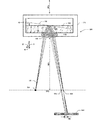
図1は本発明の1実施例に基づく傾斜検知器100を模式的に例示している。図1は何等かの特定の縮尺で描かれているものではなく、動作原理を例示するために相対的な寸法が誇張されている。流体105が、レンズ120が嵌められている床115を具備する容器110内に収容されている。光源125がフォーカルプレーン140におけるレンズ120の焦点距離135に位置されている。検知器アレイ145がレンズ120のフォーカルプレーン140の外に位置されている。傾斜検知器100は、例えば、図1には示していない測地装置の中心線150上に装着されている。
FIG. 1 schematically illustrates a
流体105は、例えば、約1.4の屈折率(nS)を有するシリコンオイルである。レンズ120は、例えば、約1.5の屈折率(nG)を有しているガラスであり且つ光源125からの光を無限遠に対してコリメートさせる。光源125は約150μmの直径の射出面積を有する発光ダイオード等の点光源である。
The fluid 105 is, for example, silicon oil having a refractive index (n S ) of about 1.4. The
光源125からの光線155はレンズ120及び流体105を介して通過し、液体105の上側表面から反射され、且つ流体105及びレンズ120を介して検知器アレイ145へ通過する。検知器アレイ145上に入射する光線が検知され且つ検知器信号へ変換される。
The
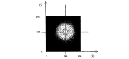
静止状態において、液体105の上側表面は重力ベクトルに対して直交している。傾斜検知器100が水平である場合には、液体105の上側表面は160において示した如くであり且つ重力ベクトルの相対的なオリエンテーション即ち配向状態はGで示した如くである。液体105の上側表面から反射された光線165はレンズ120のフォーカルプレーン140における1つの点へフォーカスする。検知器アレイ145がレンズ120のフォーカルプレーンの外に位置されると、検知器アレイ145上に入射する光線は光源125のデフォーカスされた即ち焦点のずれた画像を発生し(1つの点ではなく光のスポット)、その1つの例を図2に示してある。
In the stationary state, the upper surface of the liquid 105 is orthogonal to the gravity vector. When the
傾斜検知器100が角度αでチルトされると、液体105の上側表面は170における点線で示した如く容器110内において対応的にチルト即ち傾斜され、且つ重力ベクトルの相対的オリエンテーションはG′において示した如くである。液体105の上側表面に入射する光線と相対的な液体105の上側表面の対応する角度チルトαは、反射角度においてシフトを発生させ、点線の光線175で示した如く検知器アレイ145に入射する光線は光源125のデフォーカスされた画像を発生し、それは検知器アレイ145の表面上で位置がシフトされている。この位置シフトは図1における180において模式的に表わしてある。検知器アレイ145上の画像の位置シフトは2つの直交方向のいずれか一方又は両方において発生する場合がある。
When the
1実施例においては、検知器アレイ145は検知器要素からなるN個の行とM個の列の二次元アレイであり、例えば、検知器要素の256個の行と256個の列である。図2は検知器アレイ145上に入射する光のスポットを示しており、この光のスポットは光源125のデフォーカスされた画像である。何故ならば、検知器アレイ145はレンズ120のフォーカルプレーン140の外側に位置しているからである。図2の画像において、光のスポットの中心は検知器アレイ上に中心位置決めされており、256個の行のうちの行128及び256個の列のうちの列128にある。該光スポットの中心は、傾斜検知器100のチルト角度αが変化されると検知器アレイ上において変位される。
In one embodiment,
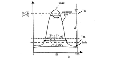
図3は検知器アレイ上に入射する光のスポットと交差する検知器アレイ要素の行からの検知器信号の振幅を示している。例えば、光のスポットの中心近くに位置している検知器アレイ145の行(例えば、256個の行のうちの行128)の夫々の検知器要素上に入射する光の検知された振幅(A/Dレベル)は実質的に310において示したような分布を有している。光のスポットの外側に位置している検知器アレイの1つの行(例えば、256個の行のうちの行1又は行256)の夫々の検知された要素上に入射する光の検知された振幅(I/Dレベル)は、実質的に320で示したような分布を有しており、このレベルはレンズ120と液体105との間の界面から反射された光等のファクタに起因するものであり、従ってバックグラウンドノイズと考えられる。バックブラウンドノイズはその他のファクタからも発生する場合がある。好適には、検知器アレイ145からの信号がスレッシュホールド330を適用することによりフィルタされ、従って光のスポットを表わす検知器信号130の部分が維持され且つバックグラウンドノイズが拒否される。検知器アレイ145からの信号の採取及び処理の例を以下に与える。
FIG. 3 shows the amplitude of the detector signal from a row of detector array elements that intersects a spot of light incident on the detector array. For example, the detected amplitude (A of light incident on each detector element of a row of detector array 145 (eg,
図3は、更に、強度分布の最大強度Imax、強度分布の最小強度Imin、及び最大強度Imaxと最小強度Iminとの間の差ΔIを表示している。線I10はIminよりΔIの10%上である強度(A/Dレベル)に対応しており、且つ線I90はIminより90%のΔI高いか又はImaxよりΔIの10%低い強度(A/Dレベル)に対応している。DmaxはImaxを超える強度を有する強度分布の部分の直径を表わしており、且つDminはIminを超える強度を有する強度分布の部分の直径を表わしている。検知器要素からなるアレイ上に形成される光源の画像はデフォーカスされた画像であるので、DmaxはDminよりも実質的により小さく、例えばDmax<0.95×Dminである。更にデフォーカスされた画像の場合においては、Dmax<0.90×Dmin又はDmax<0.80×Dmin又はDmax<0.60×Dminの場合も充足される場合がある。特に、線310の形状はガウス形状である場合がある。 FIG. 3 further displays the maximum intensity Imax of the intensity distribution, the minimum intensity Imin of the intensity distribution, and the difference ΔI between the maximum intensity Imax and the minimum intensity Imin. Line I10 corresponds to an intensity (A / D level) that is 10% above ΔI over Imin, and line I90 is an intensity (A / D) that is 90% ΔI higher than Imin or 10% below Imax ΔI. Level). Dmax represents the diameter of the portion of the intensity distribution having an intensity exceeding Imax, and Dmin represents the diameter of the portion of the intensity distribution having an intensity exceeding Imin. Since the image of the light source formed on the array of detector elements is a defocused image, Dmax is substantially smaller than Dmin, for example Dmax <0.95 × Dmin. Further, in the case of a defocused image, the case of Dmax <0.90 × Dmin, Dmax <0.80 × Dmin, or Dmax <0.60 × Dmin may be satisfied. In particular, the shape of the line 310 may be a Gaussian shape.
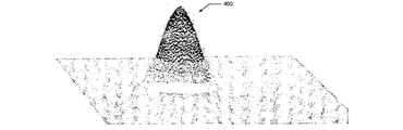
図4は図2及び図3に対応する検知された振幅分布の三次元透視表現400を示している。
FIG. 4 shows a three-
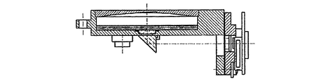
図5は光ビームを折り曲げ且つ光源及び検知器アレイを容器の側部に配置させることにより装置の高さを減少させるためにプリズムを使用する本発明に基づく傾斜検知器500の1実施例を示している。図5はいずれかの特定の縮尺に描いたものではなく、且つ動作原理を例示するために相対的な寸法を誇張してある。この形態は、2つの直交軸に関する傾斜を測定する能力を維持しながら横方向に小さな寸法を有している。流体505がレンズ520とプリズム525とが嵌め込まれた床515を有する容器510内に収容されている。光源530がフォーカルプレーン535内のレンズ520の焦点距離に位置されている。検知器アレイ540はレンズ520のフォーカルプレーン535の外側に位置されている。傾斜検知器500は、例えば、図5には示していない測地装置の中心線550とその光学的垂直経路545とを実質的に整合させて装着されている。
FIG. 5 illustrates one embodiment of a
流体505は、例えば、約1.4の屈折率nSを有するシリコンオイルである。レンズ520及びプリズム525は、例えば、約1.5の屈折率nGを有するガラスである。レンズ520は光源530からの光を無限遠に対してコリメートさせる。光源530は約150μmの直径の射出面積を有する発光ダイオード等の点光源である。
The fluid 505 is, for example, silicone oil having a refractive index n S of about 1.4. The
光源530からの光線555はプリズム525を介して通過し、プリズム525の表面560から反射され、且つレンズ520及び流体505を介して液体505の上側表面へ通過する。液体505の上側表面から反射された光線565は流体505、レンズ520及びプリズム525を介して通過し、プリズム525の表面560から反射され、且つプリズム525を介して検知器アレイ540へ通過する。検知器アレイ540上に入射する光線が検知され且つ検知器信号へ変換される。
静止状態においては、液体505の上側表面は重力ベクトルに対して直交している。傾斜検知器500が水平である場合には、液体505の上側表面は575に示した如くであり且つ重力ベクトルの相対的なオリエンテーションはGに示した如くである。液体505の上側表面から反射された光線565はレンズ520のフォーカルプレーン535における1つの点へフォーカスされる。検知器アレイ540はレンズ520のフォーカルプレーンの外側に位置されており、検知器アレイ540上に入射する光線は、例えば、図2に示したように光源530のデフォーカスされた即ち焦点がずれた画像を発生する(1つの点ではなく光のスポット)。
In the stationary state, the upper surface of the liquid 505 is orthogonal to the gravity vector. When
傾斜検知器500が角度αにチルトされると、液体505の上側表面は570における点線により示したように容器510において対応的にチルトされ且つ重力ベクトルの相対的なオリエンテーションはG′に示した如くである。液体505の上側表面上に入射する光線と相対的な液体505の上側表面の対応する角度のチルトαは、反射角度においてシフトを発生させ、従って検知器アレイ540上に入射する光線は光源530のデフォーカスされた画像を発生し、それは検知器アレイ540の表面上において位置がシフトされている。この位置シフトは図5における580において模式的に表わしてある。検知器アレイ540上の画像のこの位置シフトは、2つの直交方向のうちのいずれか一方又は両方において発生する場合がある。
When the
図5の実施例においては、光源530及び検知器アレイ540は種々の信号処理コンポーネントを例えば585及び590として示した回路ボード582上に装着されている。
In the embodiment of FIG. 5, the
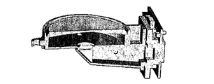
図6は本発明の1実施例に基づく傾斜検知器モジュールの断面図である。 FIG. 6 is a cross-sectional view of a tilt detector module according to one embodiment of the present invention.
図7は図6の傾斜検知器モジュールの一部切断斜視図である。 FIG. 7 is a partially cut perspective view of the tilt detector module of FIG.
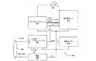
図8は本発明の実施例に基づく傾斜検知器において有用な信号処理回路800の概略図である。発光ダイオード805等の点光源がマイクロコントローラ810からの制御信号に応答して光を射出する。ダイオード805からの光線は上述した如く容器内の液体の表面から反射され、且つ反射光線は検知器アレイ815上のダイオード805の発光区域のデフォーカスされた画像を形成する。マイクロコントローラ810は制御線820、データ線825及びインター集積回路(I2C)バス830を介して検知器アレイ815と通信を行う。温度センサー835及びユニバーサルシリアルバス(USB)インターフェース840もI2Cバス830を介してマイクロコントローラ810と通信を行う。電源850がマイクロコントローラ810及びダイオード805、検知器アレイ815、温度センサー835及びUSBインターフェース840を動作させるための電力を供給する。USBインターフェース840は、図8に示していない外部プロセッサ又はディスプレイへUSBコネクタ855を介して傾斜測定信号の通信を可能とする。電源850は、例えば、図8には示していない外部供給源からUSBコネクタを介して電力供給される。
FIG. 8 is a schematic diagram of a
検知器アレイ815は任意の適宜のイメージセンサーとすることが可能であり、その多くは、アジレント(Agilent)テクノロジーズインコーポレイテッドから市販されているADCSシリーズアジレントCMOSイメージセンサー等が市販されている。これらはタイミング制御及びオンボードアナログ・デジタル(A/D)変換器と共に感応性フォトダイオード要素からなるアレイを統合する。ウインドウ寸法はアレイ全体(例えば、640×480ピクセル)から4×4ピクセルまで、又は256×256ピクセル等の中間の何等かの値にプログラムすることが可能である。統合されたタイミング制御は行及び列アドレッシング、及びプログラム可能な露光制御、フレームレート及びデータレートを与える。マイクロコントローラ810はアトメル(Atmel)コーポレイションから市販されているAVR8ビットRISC装置等の任意の適宜の装置とすることが可能である。発光ダイオード805は、ELCOS GmbHから市販されている点源ダイオードモデルPL15−R等の任意の適宜の装置とすることが可能である。
The
傾斜検知器の傾斜は、検知器アレイ上に入射する光スポットの重心を計算することにより決定される。検知器アレイのフォトダイオード要素の行の方向における傾斜は、例えば、以下の関係から決定され、 The tilt of the tilt detector is determined by calculating the centroid of the light spot incident on the detector array. The inclination in the direction of the rows of photodiode elements of the detector array is determined, for example, from the following relationship:
![]()
![]()
尚、U(r)は行の方向における傾斜であり、U0(r)は行の方向における水準点エラーであり、p(r)は行の方向における感度であり、rは行順序数であり、cは列順序数であり、A(c,r)は行c及び列rにおけるピクセルのA/D値であり、[...]は全てのピクセルにわたっての和である。検知器アレイのフォトダイオード要素の列の方向における傾斜は、例えば、次の関係から決定され、 U (r) is the slope in the row direction, U 0 (r) is the level error in the row direction, p (r) is the sensitivity in the row direction, and r is the row order number. C is the column order number, A (c, r) is the A / D value of the pixel in row c and column r, [. . . ] Is the sum over all pixels. The tilt in the direction of the rows of photodiode elements of the detector array is determined, for example, from the following relationship:
![]()
![]()
尚、U(c)は列の方向における傾斜であり、U0(r)は列の方向における水準点エラーであり、p(r)は列の方向における感度であり、rは行順序数であり、cは列順序数であり、A(c,r)は行c及び列rにおけるピクセルのA/D値であり、且つ[...]は全てのピクセルにわたっての和である。 U (c) is the slope in the column direction, U 0 (r) is the level error in the column direction, p (r) is the sensitivity in the column direction, and r is the row order number. C is the column order number, A (c, r) is the A / D value of the pixel in row c and column r, and [. . . ] Is the sum over all pixels.
チルト感度p(c),p(r)は光学系の焦点距離及びピクセル間隔に依存する。入射光強度に関する感度は、例えば、入射光に対するフォトダイオード感度の線形範囲を使用するために150(8ビット形態における256レベルのうちの)のレベルへ規制される。 The tilt sensitivity p (c), p (r) depends on the focal length of the optical system and the pixel interval. Sensitivity with respect to incident light intensity is limited to a level of 150 (out of 256 levels in an 8-bit form), for example, to use a linear range of photodiode sensitivity to incident light.
例えば、所望の限界を超えたフォトダイオード要素からの値(A/Dレベル)のみを使用することによりノイズ拒否のためのスレッシュホールド処理が実施される。 For example, threshold processing for noise rejection is performed by using only values (A / D levels) from photodiode elements exceeding a desired limit.
温度センサー835は、傾斜検知器回路のキャリブレーションのためにオプションとして設けられている。流体の屈折率は温度と共に変化し、傾斜検知器の水準点U0(r),U0(c)を変化させ、従って、広い範囲の大気温度にわたって傾斜検知器を使用するための温度キャリブレーションを与えることが望ましい。チルト感度p(c),p(r)を温度で補正することも可能である。補正定数は人工気象室内において測定し且つマイクロコントローラ810内に格納することが可能であり、従って傾斜検知器が使用中である場合に、マイクロコントローラ810は温度センサー635から大気温度値を獲得し且つその大気温度に対して適切な水準点エラー値U0(r),U0(c)に基づいて傾斜値U(r),U(c)を計算することが可能である。
A
マイクロコントローラ810はI2Cバス830を介して検知器アレイ815の動作モードを制御し、且つ計算した傾斜値をI2Cバス830を介してUSBインターフェース840へ通信する。マイクロコントローラ810は、発光ダイオード805への電流を制御することにより及び/又は露光時間を制御することにより光強度レベルを制御する。発光ダイオード805は、所望により、連続して照明させることが可能であり、又は光出力にわたってより精細な制御を与えるためにパルス動作させることが可能である。例えば、マイクロコントローラ810が15個の電流レベルを可能とする場合には、中間レベルの光出力を得るために発光ダイオード805への電流をパルス動作させることによりより細かい電流制御を得ることが可能である。1つの可能なスキームは、8−10msの期間でパルス動作させ且つ各電流レベルの間で8個のステップを与えることである(0個のパルスがオンで8個のパルスがオフから8個のパルスがオンで0個のパルスがオフまで)。
Microcontroller 810 controls the operating mode of
1実施例においては、マイクロコントローラ810は開始コマンドをI2Cバス830を介して検知器アレイ815へ送信する。動作において、検知器アレイ815はプログラムされているフォトダイオードアレイ(例えば、256×256)を介して継続的にループ動作し且つデータバス825を介して各フォトダイオードに対して8ビットレベルの値をマイクロコントローラ810へ送信する。マイクロコントローラ810が情報からなるフレームを得ると、それは傾斜値を計算し且つ計算した傾斜値を、USBケーブル855を介して再送するためにUSBインターフェース840へI2Cバス830を介して送信する。
In one embodiment, microcontroller 810 sends a start command to
1実施例においては、マイクロコントローラ810は継続的に検知器アレイ815からデータを受取り且つデータの各新たなフレームに対して新しい組の計算した傾斜値を送信する。傾斜測定の頻繁なアップデートが、例えば、装置が衝撃や振動に露呈される場合のある建設現場等の厳しい環境条件の下における装置において使用する場合に望ましい。
In one embodiment, microcontroller 810 continuously receives data from
厳しい環境条件の下において、情報の喪失を回避するために高い露光時間に対して検知器アレイをプログラムすることが望ましい。1実施例においては、露光時間がデータの1つのフレーム(例えば、256本のライン)を送信するために検知器アレイ815に対して必要とされる時間とマッチするように、露光強度が発光ダイオード805へ印加される電流を調節することにより調節される。1実施例においては、露光時間は、このラインのフォトダイオードの電荷をリセットすることによりそのラインをクリアすることと複数のライン番号におけるこのラインのフォトダイオードのデータを読み出す時間との間の時間である。この固定されたライン数は1から例えば5又はそれより多いライン等の何等かのより大きな数の範囲にわたることが可能である。
Under severe environmental conditions, it is desirable to program the detector array for high exposure times to avoid loss of information. In one embodiment, the exposure intensity is a light emitting diode such that the exposure time matches the time required for the
1実施例においては、傾斜値の計算はローリングプロセスであり、その場合に、データが1つのフレームの遅延又は1つの露光時間間隔の遅延で処理される。1実施例においては、データがフレームあたり0.2秒のレートで採取され且つマイクロコントローラ810は毎秒5組の傾斜値を計算する。1実施例においては、マイクロコントローラ810が例えば0.2秒の露光時間にわたる平均として傾斜値を計算する間にデータが継続的に採取される。1実施例においては、傾斜値は複数個のフレームの期間にわたる平均として計算され、その計算はマイクロコントローラ810におけるか又は本発明に基づく傾斜検知器を構成する装置の別個の制御器(不図示)におけるかのいずれかで発生する。 In one embodiment, the slope value calculation is a rolling process in which data is processed with a delay of one frame or a delay of one exposure time interval. In one embodiment, data is taken at a rate of 0.2 seconds per frame and the microcontroller 810 calculates 5 sets of slope values per second. In one embodiment, data is continuously collected while the microcontroller 810 calculates the slope value as an average over an exposure time of, for example, 0.2 seconds. In one embodiment, the slope value is calculated as an average over a plurality of frame periods, and the calculation is a separate controller (not shown) in the microcontroller 810 or of a device comprising a slope detector according to the present invention. Occurs in either of
実施例においては、ダイオード電流、露光時間、平均間隔等のパラメータの選択は意図された使用、予測される振動条件、大気温度、容器内の流体の静止状態を乱す装置の予測された移動及び/又はその他の考慮事項に基づいている。例えば、人間のオペレータが手作業により装置のレベリングを行う場合には、人間のオペレータは手作業のレベリングが行われる場合に即時に測定変化を見ることを望むものであるから、長期間にわたっての傾斜測定値を平均化することは望ましいことではない。手作業のレベリング動作が完了すると、人間のオペレータは改良した測定精度のために平均化が多数のフレームにわたって(例えば、3秒の期間にわたって)発生するモードへ変化することを望む場合がある。従って、装置は人間のオペレータにより選択されるべき異なる動作モードを提供することが可能である。 In an embodiment, the selection of parameters such as diode current, exposure time, average interval, etc. is intended use, predicted vibration conditions, atmospheric temperature, predicted movement of the device that disturbs the rest of the fluid in the container, and / or Or based on other considerations. For example, if a human operator manually levels the device, the human operator wants to see the measurement change immediately when manual leveling is performed, so tilt measurements over a long period of time It is not desirable to average Once the manual leveling operation is complete, the human operator may wish to change to a mode where averaging occurs over a number of frames (eg, over a 3 second period) for improved measurement accuracy. Thus, the device can provide different modes of operation to be selected by a human operator.
本発明に基づく実施例は、以下の特性のうちの1つ又はそれ以上を有することが可能である。第一に、光ビームは90度に近い角度で液体表面に入射する。CCDライン検知器を使用する従来の装置は、より大きな光エネルギを与えるために入射光の全反射に対し約45度の入射角度を有している。CMOSフォトダイオードアレイ等のエリアセンサーは、より少ないエネルギを必要とし、従って約2.5%の反射エネルギが充分である。より大きな入射角度はよりコンパクトな傾斜検知器形態を可能とする。 Embodiments in accordance with the present invention can have one or more of the following characteristics. First, the light beam is incident on the liquid surface at an angle close to 90 degrees. Conventional devices using CCD line detectors have an incident angle of about 45 degrees with respect to total reflection of incident light to provide greater light energy. Area sensors such as CMOS photodiode arrays require less energy, so about 2.5% reflected energy is sufficient. A larger angle of incidence allows for a more compact tilt detector configuration.
第二に光源はドット源である。ドット源を使用することが可能である理由は、検知器アレイが高感度の要素(例えば、CMOSダイオード)及び、それからサブピクセル精度で検知された信号の重心を計算することが可能なデータを供給する内部アナログ・デジタル変換器を有しているからである。ピクセル寸法(フォトダイオード間隔)は、例えば、7μmである。 Second, the light source is a dot source. The reason why the dot source can be used is that the detector array provides sensitive elements (eg, CMOS diodes) and data from which the centroid of the detected signal can then be calculated with sub-pixel accuracy. This is because it has an internal analog / digital converter. The pixel dimension (photodiode interval) is, for example, 7 μm.
第三に、検知器アレイ上のドットの画像は、検知器アレイをレンズのフォーカルプレーンの外に配置させることによりデフォーカスされている。例えば、約150μm直径のドット源からのドットの検知器アレイ上の画像は約250μmのエリアへデフォーカスされる。画像の重心を計算する場合の高精度のために、シャープな画像端部を有するものでないことが有益的である。ピクセル振幅(フォトダイオードレベル)のガウス分布の端部は、サブピクセル精度でドット画像の重心を計算するために使用される。センサーパッケージ内のプロセッサ(マイクロコントローラ)でもって、該画像の重心が実時間で計算される。 Third, the dot image on the detector array is defocused by placing the detector array outside the focal plane of the lens. For example, an image on a detector array of dots from a dot source of about 150 μm diameter is defocused to an area of about 250 μm. For high accuracy when calculating the center of gravity of the image, it is beneficial not to have sharp image edges. The end of the Gaussian distribution of pixel amplitude (photodiode level) is used to calculate the centroid of the dot image with subpixel accuracy. With the processor (microcontroller) in the sensor package, the center of gravity of the image is calculated in real time.
第四に、液体と接触しているレンズ表面(例えば、液体105と接触しているレンズ120の上側表面及び液体505と接触しているレンズ520の上側表面)は非平坦状である。ドット源からの光が該液体の上側表面に対してほぼ直交する角度で入射すると、低い反射率(例えば、約2.5%)のために信号は低い。平坦状の上側レンズ表面はレンズ/液体界面における反射を発生させ、検知器アレイに入射するスポットの中央領域におけるノイズを増加させる傾向となる。凸状又は凹状の上側レンズ表面は、広い区域にわたりレンズ・液体界面において発生する反射を分散させる傾向となり、興味のある区域(検知器アレイに入射する光のスポットの中心)におけるより高い信号対ノイズ比を発生させる。該レンズのアクティブなフォーカシング表面は凸状であり且つ液体と接触しているレンズの非アクティブな表面は凸状(図1におけるように)又は凹状(図5におけるように)である。
Fourth, the lens surface in contact with the liquid (eg, the upper surface of the
1実施例において、フォーカルプレーンはレンズの後の単一の焦点距離に位置されている。1実施例においては、光源及び検知器アレイのうちの少なくとも一方がフォーカルプレーンの外に位置しており、従って検知器アレイに入射する光源の画像は、例えば、ガウス分布でデフォーカスされる。1実施例においては、全アパーチャが使用される。 In one embodiment, the focal plane is located at a single focal length after the lens. In one embodiment, at least one of the light source and the detector array is located outside the focal plane, so the image of the light source incident on the detector array is defocused, for example, with a Gaussian distribution. In one embodiment, all apertures are used.
1実施例においては、レンズは液体と接触していないが、液体の近くに配置されており且つウインドウが設けられており、ドット源からの光はレンズ及びウインドウを介して液体内へ通過し且つウインドウ及びレンズを介して検知器アレイへ戻る。ウインドウが設けられる場合には、1実施例においては、液体と接触するウインドウ表面は非平坦状である(例えば、凸状又は凹状)。 In one embodiment, the lens is not in contact with the liquid, but is located near the liquid and provided with a window, and light from the dot source passes through the lens and window into the liquid and Return to the detector array through the window and lens. Where a window is provided, in one embodiment, the window surface that contacts the liquid is non-planar (eg, convex or concave).
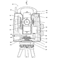
本発明に基づく実施例は、傾斜検知器を組込んだ測地装置を包含している。例えば、図9は本発明の1実施例に基づくトータルステーションの部分断面正面図を示しており、且つ図10はこのようなトータルステーションの機能ブロック図である。 Embodiments in accordance with the present invention include geodetic devices that incorporate tilt detectors. For example, FIG. 9 shows a partial sectional front view of a total station according to one embodiment of the present invention, and FIG. 10 is a functional block diagram of such a total station.
図9を参照すると、トータルステーション900は支持軸906周りに回転するために調節可能な整準台904上に装着されているアリダード902を有しており、支持軸906はアリダード902が水平である場合に垂直である。光学的中心線(視線方向)912を具備するテレスコープ910を有するテレスコープユニット908が、支持軸906に直交するエレベーション軸914周りに回転するために装着されている。
Referring to FIG. 9, the
制御可能な水平ドライブ916が制御信号に応答して支持軸906周りにアリダード902を回転させる。整準台904に関して固定されている目盛りが付けられたリング918のマーキングが、アリダード902が回転される場合に、水平角度センサー920により検知される。制御可能な垂直ドライブ922は制御信号に応答してエレベーション軸914周りにテレスコープユニット908を回転させる。テレスコープユニット908に関して固定されている目盛りの付いたリング924のマーキングが、テレスコープユニット908が回転される場合に、垂直角度センサー926によって検知される。手動的に動作可能なノブを具備する水平制御部928及び手動的に動作可能なノブを具備する垂直制御部930は、夫々、水平ドライブ916及び垂直ドライブ922の制御に対するユーザ入力を与える。
A controllable
アリダード902は支持軸906周りを任意の所望の角度へ回転可能であり且つテレスコープユニット920はエレベーション軸914周りを任意の所望の角度へ回転可能であり、任意に位置された外部ターゲットに対してテレスコープ910へ照準させるために365度を超える角度であっても可能である。スリップリング932は、外部電源(図10に示してある)からアリダード902への電力の伝達及び/又はアリダード902と外部制御ユニット(図10に示してある)との間のデータ及びコマンドの通信を与える。スリップリング934は、アリダード902からテレスコープユニット908への電力の伝達及びアリダード902とテレスコープユニット908との間のデータ及びコマンドの通信を与える。
The
アリダード902は容易な運搬のためのハンドル936を包含している。支持軸906と同軸上に垂直下方向への光ビームを射出させるか又は選択した点において938における小さなテレスコープを介して観察することのいずれかにより調査目標又はその他の選択した点にわたってトータルステーション900の手動的位置決めを簡単化させるために光学的下げ振り938が設けられている。図1−8を参照して説明したような傾斜検知器940が、2つの相互に直交する方向におけるアリダード902の傾斜を表わす信号を供給し、従って、支持軸906が垂直であり且つエレベーション軸が水平であるようにトータルステーションをセットアップすることを可能とする。傾斜センサー940が図5,6,7の形状を有している場合には、該センサーをアリダードの側部の代わりに光学的下げ振り938の側の中心で且つ装置の回転期間中の擾乱を最小とするために支持軸906と同軸上に装着することが望ましい。
The
アンテナ944を具備する無線中心モジュール942が、トータルステーション900と外部無線中心制御ユニット(図10に示してある)との間のデータ及びコマンドの通信を与える。バッテリ946が、トータルステーション900に対する電力を供給するために設けられている。トータルステーション900は、又、キーパッド及び/又はその他の入力装置及びディスプレイスクリーン(図10に示してある)を具備する着脱自在な制御ユニットを有している。
A
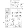
図10のブロック線図1000を参照すると、点線は夫々の要素が配置されている物理的なユニットを表わしている。アリダード902内においてメインプロセッサ1004及びトータルステーションのその他の要素へ電力を供給するために電源1002がバッテリ946へ接続している。メインプロセッサ1004は、図示していない関連するメモリ、プログラム格納部等を包含している。電源接続はコンポーネントの機能的関係をぼかすことがないように図示していない。電力が電源1002からトータルステーションのコンポーネントへ個々の接続を介して及び/又は電力分布とデータ通信とを結合させるユニバーサルシリアルバス(USB)等のバスを介して供給される。同様に、メインプロセッサ1004とトータルステーションのその他のコンポーネントとの間の通信は、個々の接続を介して及び/又はユニバーサルシリアルバス等の共通バス1006を介して行われる。スリップリング932は電源1010及び/又は外部制御ユニット1012を具備する外部ユニット1008への電気的接続を与える。スリップリング934はメインプロセッサ1004とテレスコープユニット908のコンポーネントとの間のデータ通信及びテレスコープユニット908のコンポーネントへの電力の供給を与える。該機能的要素の各々はメインプロセッサ1004の制御下にあり且つ測定結果をメインプロセッサ1004へ送信すべく命令される場合がある。
Referring to the block diagram 1000 of FIG. 10, the dotted lines represent the physical units in which the respective elements are arranged. A power supply 1002 is connected to the
水平制御部928、垂直制御部930及びフォーカス制御部1014は、アリダード902、エレベーションテレスコープユニット908及びテレスコープ910の光学的フォーカスの方位方向におけるオリエンテーションを設定するためのコマンドの手動的入力を与える。該コマンドはインターフェース1016を介してメインプロセッサ1004へ通信される。着脱自在なコンソール1018はディスプレイスクリーン1020及びキーパッド及び/又はタッチスクリーン等の入力装置1022を与える。コンソール1018は人間のオペレータとトータルステーションとの間の通信を司り、コマンド及びデータの手動的入力及びユーザメニュー及びデータの表示を可能とする。コンソール1018はメインプロセッサ1004との通信を管理し且つ測地計算等のその他の作業をサポートするための入力/出力プロセッサ1024を包含している。コンソール1018はコネクタ1026によってメインプロセッサ1004及び電源1002と接続されている。
無線通信モジュール942はバス1006を介してメインプロセッサ1004と及びアンテナ944を介してアンテナ1028を具備する無線通信制御ユニット1026と通信を行う。トータルステーションは、例えば、測定ターゲットに位置されている場合に、無線通信制御ユニット1026から遠隔的に制御することが可能である。
The
テレスコープユニット908は距離測定モジュール1030、サーボフォーカスモジュール1032、トラッカーモジュール1034及びトラッキングアシスタントモジュール1036を包含している。
距離測定モジュール1030は、例えば、ターゲットに向けて光を射出し且つ反射光の位相変化を検知することにより又はターゲットに向けて光パルスを射出し且つ反射パルスの飛行時間を決定することにより、トータルステーションからターゲットへの距離を測定する。距離測定計算は、距離測定モジュール1030の回路において及び/又はメインプロセッサ1004において実施される。
The
サーボフォーカスモジュール1032は、フォーカス制御部1014の手動的調節に応答して及び/又はサーボフォーカスモジュール1032内のオートフォーカス回路に応答してメインプロセッサ1004からの信号に依存して、テレスコープ光学系の制御可能なフォーカスを与える。
The servo focus module 1032 is responsive to manual adjustment of the
トラッカーモジュール1034は、トータルステーションが自動的にターゲットにテレスコープを照準させ且つターゲットが移動する場合にターゲットに追従することを可能とする。トラッカーモジュール1034は、テレスコープ光学系を介して幅狭の光ビームを射出する。この光は、ターゲットから反射された場合に、センサーにより検知され、該センサーは追跡信号をメインプロセッサ1004へ送信してアジマス即ち方位角及びエレベーション即ち仰角の必要とされる変化を表示する。
The tracker module 1034 allows the total station to automatically aim the telescope at the target and follow the target as the target moves. The tracker module 1034 emits a narrow light beam through the telescope optical system. This light is detected by a sensor when reflected from the target, which sends a tracking signal to the
トラッキングアシスタントモジュール1036は、テレスコープの視線方向の片側又は反対側に位置された場合に人間のオペレータが夫々の異なる色を見るように指向される光を射出することにより、人間のオペレータが移動可能なターゲットをテレスコープの光軸内に配置させることを助ける。 The tracking assistant module 1036 allows the human operator to move by emitting light that is directed to the human operator to see each different color when positioned on one side or the other side of the telescope's line of sight Helping to position the target within the telescope's optical axis.
アリダード902の方位方向オリエンテーションは水平角度センサー920から受取った信号からメインプロセッサ1004に対して既知である。アリダード902の方位方向オリエンテーションは、メインプロセッサ1004から水平駆動制御部1040へ送信される信号により命令される。水平駆動部916は水平駆動制御部1040に応答して支持軸906周りにアリダード902を回転させる。テレスコープユニット908のエレベーションは垂直角度センサー926から受取った信号からメインプロセッサ1004にとって既知である。テレスコープユニット908のエレベーションは、メインプロセッサ1004から垂直駆動制御部1042へ送信される信号により命令される。垂直駆動部922は垂直駆動制御部1042に応答してエレベーション軸914周りにテレスコープユニット908を回転させる。
The azimuthal orientation of
メインプロセッサ1004は幾つかの供給源、即ち制御部928及び930の手動的設定、入力装置1022を介してのデータの手動的エントリ、無線通信制御ユニット1028からの遠隔コマンド、及びトラッキング機能がイネーブルされている場合のトラッカー1036からの自動的信号、のうちの1つから所望の方位角及び仰角を決定する。
The
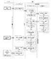
図11は本発明の実施例に基づくトータルステーション等の傾斜検知器及び測地装置の動作を例示したフローチャート1100を示している。理解を容易にさせるために、図11のフローチャートは、最初に、人間のオペレータにより実施される機能と装置により実施される機能との間で分けられている。装置内において実施される機能は、メインプロセッサ1004等の装置のメインプロセッサにより実施されるものと傾斜検知器940等の装置の傾斜検知器により実施されるものとの間で分けられている。傾斜検知器内に実施される機能は、更に、マイクロコントローラ810等の傾斜検知器のマイクロコントローラにより実施されるものと検知器アレイ815等の傾斜検知器の検知器アレイにより実施されるものとの間で分けられている。
FIG. 11 shows a flowchart 1100 illustrating the operation of an inclination detector such as a total station and a geodetic device according to an embodiment of the present invention. For ease of understanding, the flowchart of FIG. 11 is initially divided between functions performed by a human operator and functions performed by the device. The functions performed in the device are divided between those performed by the main processor of the device such as the
人間のオペレータが開始コマンド1102で装置を開始させる。メインプロセッサは1104において動作を開始させ且つ1106においてマイクロコントローラを開始させるためのコマンドを送信する。マイクロコントローラは1108において動作を開始し、1110において検知器アレイを開始させるためのコマンドを送信し、且つ1112において点源LEDを照明させるための電力を送る。検知器アレイは1114において動作を開始し且つ1116においてデータセットの採取を開始する。データセットが採取されると(例えば、1つの光検知器のA/D値)、検知器アレイは1118において採取したデータを1120においてマイクロコントローラへ送信する。検知器アレイは1124において検知器要素をインクリメントさせる。検知器アレイはそれが動作状態に留まる限り、データの採取及び送信を継続して行う。 A human operator starts the device with a start command 1102. The main processor sends a command to start operation at 1104 and to start the microcontroller at 1106. The microcontroller begins operation at 1108, sends a command to start the detector array at 1110, and sends power to illuminate the point source LED at 1112. The detector array begins operation at 1114 and begins collecting data sets at 1116. When the data set is acquired (eg, the A / D value of one photodetector), the detector array transmits the data acquired at 1118 to the microcontroller at 1120. The detector array increments the detector element at 1124. The detector array continues to collect and transmit data as long as it remains operational.
マイクロコントローラにより受取られるデータセット1118は1126においてメモリ内に格納される。マイクロコントローラは、完全なデータフレームが採取されたか否かを1128においてチェックする(例えば、点源LEDの完全なデフォーカスされた画像を表わすデータセットの総数)。マイクロコントローラは、オプションとして、温度補正した傾斜測定値を計算する場合に使用すべき温度値を1130において採取する。平均化パラメータは、オプションとして、1132において人間の入力から及び/又は予めプログラムしたか又はデフォルトパラメータから供給される。メインプロセッサは、オプションとして、1134において適宜のパラメータを設定し及び/又はオプションとして平均化パラメータ1136をマイクロコントローラへ送信する。マイクロコントローラは、オプションとして、その平均化パラメータを設定する。
A
マイクロコントローラは1140において傾斜測定値を計算し、オプションとして温度補正を適用し且つオプションとして複数のデータセット及び/又は複数のデータフレームにわたり平均化する。マイクロコントローラは1142において計算した傾斜測定値をメインプロセッサへ送信し且つデータの別のフレームを待機する。メインプロセッサは、オプションとして、1146において指定した時間間隔にわたっての傾斜測定値を平均化する。メインプロセッサは、傾斜測定信号を1150においてディスプレイへ送信する。ディスプレイスクリーン又はその他の適宜の出力装置は人間のオペレータの情報のための傾斜測定値を表示する。 The microcontroller calculates the tilt measurements at 1140, optionally applying temperature correction and optionally averaging over multiple data sets and / or multiple data frames. The microcontroller sends the tilt measurement calculated at 1142 to the main processor and waits for another frame of data. The main processor optionally averages the slope measurements over the time interval specified at 1146. The main processor sends a tilt measurement signal at 1150 to the display. A display screen or other suitable output device displays tilt measurements for human operator information.
角度センサーは角度データを表示し且つ格納するためのみならず、角度計算のための高速データでサーボシステムをサポートするように構成されている。更に、角度測定システムは以下のことを補償する。 The angle sensor is configured not only to display and store angle data, but also to support the servo system with high speed data for angle calculation. In addition, the angle measurement system compensates for the following:
・垂直軸の逸れに対する自動補正
・コリメーションエラーの自動補正
・トラニオン軸チルトの自動補正
・照準エラーを減少させるための演算的平均化。
-Automatic correction for vertical axis deviation-Automatic correction of collimation error-Automatic correction of trunnion axis tilt-Computational averaging to reduce aiming error.
垂直軸における逸れは、不安定な土地又は道路舗装の加熱等の土地粘度における変化の結果として三脚の脚部のうちの1つ又はそれ以上が移動する場合に発生する場合がある。この移動に対する補正は正確な測定を確保する。 Deviations in the vertical axis may occur when one or more of the tripod legs move as a result of changes in land viscosity, such as heating of unstable land or road pavements. Correction for this movement ensures an accurate measurement.
最も最近のトータルステーションは整準誤りにより発生される垂直軸における何等かの逸れに対する水平及び垂直角度を自動的に補正する二軸補償器が装備されている。本発明の実施例によれば、レベル補償器センサーが、装置の振動及び回転に対する感度を最小とさせるために装置の中心に装着されている。その装着設備は、好適には、絶対的なレベル補償器を与えることが可能であるように最も高い安定性に対して設計されており、従って該補償器は装置がパワーアップされた直ぐ後に完全な正確度で活性化することが可能である。更に、該補償器のルーチンのキャリブレーションのために自動的手順を設けることが可能である。そのキャリブレーションプロセスは、装置の360度の回転期間中に装置のバランスされた垂直軸と相対的に水平基準面を確立することが関与する。基準面のオリエンテーションは、大きな温度変動又はその他の機械的応力と共に僅かに変化する場合がある。 Most recent total stations are equipped with a biaxial compensator that automatically corrects the horizontal and vertical angles for any deviation in the vertical axis caused by leveling errors. According to an embodiment of the present invention, a level compensator sensor is mounted in the center of the device to minimize sensitivity to vibration and rotation of the device. The mounting equipment is preferably designed for the highest stability so as to be able to provide an absolute level compensator, so that the compensator is completely after the device is powered up. It is possible to activate with high accuracy. Furthermore, an automatic procedure can be provided for routine calibration of the compensator. The calibration process involves establishing a horizontal reference plane relative to the balanced vertical axis of the device during a 360 degree rotation of the device. The orientation of the reference plane may change slightly with large temperature fluctuations or other mechanical stresses.
整準誤りに対する水平及び垂直角度の補正に加えて、水準誤りにより発生される照準エラーが本発明の実施例に基づいて補正される。整準誤り補正は装置を再度照準させるためにサーボ駆動部へ印加される。例えば、真の垂直線を得ることが可能であることを確保するために垂直線を拡張する場合に照準を補正することが可能である。その結果は、装置が正しい位置において正確に照準される一方、水平及び垂直角度が整準誤りに対して補正される。この能力は、整準誤りが正確な角度測定値を与えるために補正されることを確保する。 In addition to horizontal and vertical angle correction for leveling errors, aiming errors caused by level errors are corrected according to an embodiment of the present invention. Leveling error correction is applied to the servo drive to aim the device again. For example, the aim can be corrected when extending the vertical line to ensure that it is possible to obtain a true vertical line. The result is that the device is accurately aimed at the correct position while the horizontal and vertical angles are corrected for leveling errors. This ability ensures that leveling errors are corrected to give an accurate angle measurement.
測定された水平及び垂直角度に影響を与えるコリメーションエラーも本発明の実施例に基づいて補正される。水平コリメーションエラーは、視線方向とトラニオン軸に対して垂直な面との間の差であり、垂直コリメーションエラーは垂直メモリ盤ゼロと垂直軸との間の差である。従来、両方の装置面上の角度を観察することによりコリメーションエラーが除去されていた。本発明の実施例によれば、コリメーションエラーは測定前コリメーションテストを実施することにより予め決定することが可能である。コリメーションエラーを計算し且つ夫々の補正値を装置内に格納することを可能とするために角度測定値が両方の装置面上で観察される。次いで、コリメーション補正値はその後の全ての角度測定値に対して適用される。単一面上で観察された角度は、従って、コリメーションエラーに対して補正され、それにより両方の装置面上で測定することの必要性を取除いている。トラッカーユニットは、自動的にターゲットをロックし且つ追跡することを可能とする。ターゲットへの照準は装置により実施されるので、水平及び垂直コリメーションの効果は手動的照準期間中に経験されるものと同様である。トラッカーユニットにおけるコリメーションエラーを補正するために、オートロックコリメーションテストを実施することが可能である。オートロックコリメーションテストは、両方の装置面上におけるターゲットに対する角度測定値を自動的に観察する。次いで、オートロックコリメーションエラーが計算され且つ夫々の補正値が装置内に格納される。オートロックコリメーション補正値は、次いで、オートロックがイネーブルされている場合に観察されるその後の全ての角度測定値に対して適用される。従って、単一面上で観察される角度はコリメーションエラーに対して補正され、それにより両方の装置面上で測定することの必要性を取除いている。 Collimation errors that affect the measured horizontal and vertical angles are also corrected based on embodiments of the present invention. Horizontal collimation error is the difference between the line-of-sight direction and the plane perpendicular to the trunnion axis, and vertical collimation error is the difference between the vertical memory board zero and the vertical axis. Conventionally, collimation errors have been removed by observing the angles on both device surfaces. According to an embodiment of the present invention, the collimation error can be determined in advance by performing a pre-measurement collimation test. Angle measurements are observed on both device planes in order to be able to calculate collimation errors and store the respective correction values in the device. The collimation correction value is then applied to all subsequent angle measurements. The angle observed on a single surface is therefore corrected for collimation error, thereby eliminating the need to measure on both device surfaces. The tracker unit makes it possible to automatically lock and track the target. Since aiming at the target is performed by the device, the effects of horizontal and vertical collimation are similar to those experienced during manual aiming. An auto-lock collimation test can be performed to correct the collimation error in the tracker unit. The auto-lock collimation test automatically observes the angle measurement relative to the target on both device surfaces. The autolock collimation error is then calculated and the respective correction values are stored in the device. The autolock collimation correction value is then applied to all subsequent angle measurements that are observed when autolock is enabled. Thus, the angle observed on a single surface is corrected for collimation error, thereby eliminating the need to measure on both device surfaces.
トラニオン軸チルトエラーも本発明の実施例に基づいて自動的に補正される。トラニオン軸チルトエラーはトラニオン軸と垂直軸に対して垂直な面との間の差である。トラニオン軸チルトエラーは、測定前トラニオン軸チルトテストを実施することにより決定することが可能である。水平チルト軸エラーを計算し且つ夫々の補正値を装置内に格納することを可能とするために両方の装置面上で角度測定値が観察される。次いで、水平チルト軸補正値が全てのその後の水平角度に対して適用される。 The trunnion axis tilt error is also automatically corrected based on the embodiment of the present invention. The trunnion axis tilt error is the difference between the trunnion axis and the plane perpendicular to the vertical axis. The trunnion axis tilt error can be determined by performing a pre-measurement trunnion axis tilt test. Angular measurements are observed on both device planes in order to be able to calculate the horizontal tilt axis error and store the respective correction values in the device. The horizontal tilt axis correction value is then applied to all subsequent horizontal angles.
整準誤りに対する視線方向の補償も本発明の実施例に基づいて実施することが可能である。従来のトータルステーションは、整準の誤りの効果に対する水平及び垂直角度を補正するために二軸補償器を使用している。然しながら、その角度補正は整準誤りにより導入されるエイミング(aiming)即ち照準エラーを補償するものではない。本発明の実施例によれば、チルトセンサー出力が整準誤りに対する水平及び垂直角度を補正するばかりでなく、整準誤りにより発生される照準エラーも補正するために使用される。整準誤り補正は装置を正しい位置に対して再度照準させるためにサーボドライブへ適用される。その結果は、装置が正しい位置において正確に照準されると共に水平及び垂直角度が整準誤りに対して補正されることとなる。 Compensation of the line-of-sight direction for leveling errors can also be performed based on the embodiment of the present invention. Conventional total stations use biaxial compensators to correct the horizontal and vertical angles for the effects of leveling errors. However, the angle correction does not compensate for aiming errors introduced by leveling errors. According to an embodiment of the present invention, the tilt sensor output is used not only to correct horizontal and vertical angles for leveling errors, but also to correct aiming errors caused by leveling errors. Leveling error correction is applied to the servo drive to aim the device again at the correct position. The result is that the device is accurately aimed at the correct position and the horizontal and vertical angles are corrected for leveling errors.
従来のトータルステーションの制限は、単純に垂直衛御ノブを移動させることにより同一の水平角度で垂直線を上又は下へ拡張させることの能力である。この能力は、装置が全ての軸が完全に調節された状態で完全に整準されていることを要求する。実際上、装置は垂直方向に回転され、水平角度が僅かに変化する。真の垂直線を得るためには、水平角度が調節されねばならない。本発明の実施例によれば、垂直制御ノブが回転される場合に水平角度及び照準を固定した値に自動的に調節するために補償及びエラー情報が使用される。従って、単純に垂直制御ノブを回転させることにより完全な垂直線を拡張させることが可能である。 A limitation of the conventional total station is the ability to extend the vertical line up or down at the same horizontal angle by simply moving the vertical control knob. This capability requires the device to be fully leveled with all axes fully adjusted. In practice, the device is rotated vertically and the horizontal angle changes slightly. To obtain a true vertical line, the horizontal angle must be adjusted. According to an embodiment of the present invention, compensation and error information is used to automatically adjust the horizontal angle and aim to fixed values when the vertical control knob is rotated. Therefore, it is possible to extend the complete vertical line by simply rotating the vertical control knob.
垂直線を拡張させるために使用される技術と同様に、与えられた水平方向と正確に反対の方向に水平な直線を設定する従来の方法は、単純に垂直制御ノブを回転させることによりテレスコープを180度トランシットさせることである。従来の装置では、この技術は正確な結果のために水平コリメーションエラーなしで完全に調節された軸を必要とする。本発明の実施例によれば、垂直制御ノブが回転される場合に水平角度を固定した値に自動的に調節させるためにコリメーション及び補償器エラー情報が使用される。垂直制御ノブのみを回転させることにより水平角度は正確な直線方向を与えるために調節される。 Similar to the technique used to extend the vertical line, the traditional method of setting a horizontal straight line in exactly the opposite direction to the given horizontal direction is simply to rotate the vertical control knob to telescope. Is 180 degrees. In conventional devices, this technique requires a perfectly adjusted axis without horizontal collimation errors for accurate results. In accordance with an embodiment of the present invention, collimation and compensator error information is used to automatically adjust the horizontal angle to a fixed value when the vertical control knob is rotated. By rotating only the vertical control knob, the horizontal angle is adjusted to give an accurate linear direction.
説明の便宜上、ここに記載した実現例のルーチンの特徴の全てが示され且つ記載されているものではない。理解されるように、いずれかのこのような実際の実現例の開発においては、応用及びビジネスに関連する拘束条件の遵守等の開発者の特定の目標を達成するために多くの実現例に特定の決定がなされねばならず、且つこれらの特定の目標は実現例毎に且つ開発者毎に異なるものである。更に、理解されるように、このような開発努力は複雑且つ時間がかかる場合があるが、それにも拘わらず、本開示の利益を有する当業者にとって日常のエンジニアリング作業である。 For convenience of explanation, not all features of the implementation routines described herein are shown and described. As will be appreciated, in the development of any such actual implementation, a number of implementations are identified to achieve the developer's specific goals, such as compliance with application and business related constraints. Decisions must be made, and these specific goals will vary from implementation to implementation and from developer to developer. Further, as will be appreciated, such development efforts may be complex and time consuming, but nevertheless are routine engineering tasks for those skilled in the art having the benefit of this disclosure.
本発明に基づく実施例及び適用例について示し且つ説明したが、本開示の利益を有する当業者にとって、上述したもの以外のより多くの修正例がここにおける発明概念から逸脱することなしに可能なものであることは明らかである。従って、本発明は特許請求の範囲の精神を除いて制限されるべきものではない。 While embodiments and applications in accordance with the present invention have been shown and described, those skilled in the art having the benefit of this disclosure may have more modifications than those described above without departing from the inventive concepts herein. Obviously. Accordingly, the invention is not to be restricted except in the spirit of the appended claims.
Claims (33)
レンズ(120)、
液体表面(160)に向かってレンズ(120)を介して光を射出する点源(125)、
反射表面(160)から反射された光がレンズ(120)を介して検知要素上通過するように位置されている検知要素の二次元アレイ(140)であって、各検知器要素が入射光の振幅に対応する値を発生する二次元アレイ(145)、
検知器要素上に形成された画像の重心を計算するために検知器要素により発生された値に応答するプロセッサ(810)、
を有しており、計算された重心が容器(110)の傾斜に依存する装置。 A container (110) containing a liquid (105) having a reflective surface (160);
Lens (120),
A point source (125) that emits light through the lens (120) towards the liquid surface (160);
A two-dimensional array (140) of sensing elements positioned such that light reflected from the reflective surface (160) passes over the sensing elements via a lens (120), each detector element being configured for incident light A two-dimensional array (145) for generating values corresponding to the amplitudes,
A processor (810) responsive to a value generated by the detector element to calculate a centroid of an image formed on the detector element;
And the calculated center of gravity depends on the inclination of the container (110).
(i)本装置の軸の垂直からの逸れに対する補正、及び
(ii)コリメーションエラーに対する補正、
のうちの少なくとも1つを決定するために該計算した重心を使用する装置。 21. One of claims 19 and 20, wherein the processor is
(I) correction for deviations from the vertical axis of the device, and (ii) correction for collimation errors,
An apparatus that uses the calculated center of gravity to determine at least one of
(i)照準補償、
(ii)垂直線拡張、及び
(iii)水平線拡張、
のうちの少なくとも1つを決定するために該計算した重心を使用する装置。 The processor of claim 20, wherein the processor
(I) sighting compensation,
(Ii) vertical line extension; and (iii) horizontal line extension;
An apparatus that uses the calculated center of gravity to determine at least one of
レンズ(120)を介して点源(125)からの光を容器(110)内に収容されている反射性液体表面(160)へ向かって射出させ、
液体表面(160)から反射され且つレンズ(120)を介して通過する検知器要素のアレイ(145)上に入射する光を検知して該検知器要素の各々に入射する光の検知された強度を表わすデータを採取するためにアレイ(145)上に点源(125)のデフォーカスしたイメージを形成させ、
該データから重心を決定し、該重心が容器(110)の傾斜を表わしている、
ことを包含している方法。 In the method of determining the slope,
Light from the point source (125) is emitted through the lens (120) toward the reflective liquid surface (160) contained in the container (110);
Detected light incident on an array (145) of detector elements reflected from the liquid surface (160) and passing through the lens (120) and detected intensity of light incident on each of the detector elements Forming a defocused image of the point source (125) on the array (145) to collect data representing
Determining the center of gravity from the data, the center of gravity representing the inclination of the container (110);
The method that encompasses that.
Applications Claiming Priority (2)
| Application Number | Priority Date | Filing Date | Title |
|---|---|---|---|
| US64351305P | 2005-01-12 | 2005-01-12 | |
| PCT/EP2006/000225 WO2006074929A1 (en) | 2005-01-12 | 2006-01-12 | Inclination detection methods and apparatus |
Publications (2)
| Publication Number | Publication Date |
|---|---|
| JP2008527357A true JP2008527357A (en) | 2008-07-24 |
| JP2008527357A5 JP2008527357A5 (en) | 2009-02-26 |
Family
ID=36228648
Family Applications (1)
| Application Number | Title | Priority Date | Filing Date |
|---|---|---|---|
| JP2007550753A Pending JP2008527357A (en) | 2005-01-12 | 2006-01-12 | Tilt detection method and apparatus |
Country Status (7)
| Country | Link |
|---|---|
| US (3) | US7388658B2 (en) |
| EP (1) | EP1836456B1 (en) |
| JP (1) | JP2008527357A (en) |
| CN (1) | CN101103249B (en) |
| AT (1) | ATE475865T1 (en) |
| DE (1) | DE602006015770D1 (en) |
| WO (1) | WO2006074929A1 (en) |
Cited By (2)
| Publication number | Priority date | Publication date | Assignee | Title |
|---|---|---|---|---|
| JP2016109602A (en) * | 2014-12-09 | 2016-06-20 | 株式会社トプコン | Inclination detector |
| JP2019078682A (en) * | 2017-10-26 | 2019-05-23 | 日本電気株式会社 | Laser distance measuring device, laser distance measuring method, and position adjustment program |
Families Citing this family (43)
| Publication number | Priority date | Publication date | Assignee | Title |
|---|---|---|---|---|
| US7388658B2 (en) | 2005-01-12 | 2008-06-17 | Trimble Jena Gmbh | Inclination detection methods and apparatus |
| US8331888B2 (en) * | 2006-05-31 | 2012-12-11 | The Boeing Company | Remote programmable reference |
| WO2009106144A1 (en) | 2008-02-29 | 2009-09-03 | Trimble | Automated calibration of a surveying instrument |
| US8289528B2 (en) * | 2008-03-07 | 2012-10-16 | Trimble Ab | Tilt sensor for a measuring instrument |
| US9482755B2 (en) | 2008-11-17 | 2016-11-01 | Faro Technologies, Inc. | Measurement system having air temperature compensation between a target and a laser tracker |
| US8184276B2 (en) | 2008-12-08 | 2012-05-22 | Carl Embry | Continuous index of refraction compensation method for measurements in a medium |
| WO2010143108A2 (en) | 2009-06-11 | 2010-12-16 | Koninklijke Philips Electronics N.V. | Optical scanner |
| DE102009042123B3 (en) * | 2009-09-18 | 2011-02-10 | Trimble Jena Gmbh | Geodetic instrument and method for this |
| US8724119B2 (en) | 2010-04-21 | 2014-05-13 | Faro Technologies, Inc. | Method for using a handheld appliance to select, lock onto, and track a retroreflector with a laser tracker |
| US9377885B2 (en) | 2010-04-21 | 2016-06-28 | Faro Technologies, Inc. | Method and apparatus for locking onto a retroreflector with a laser tracker |
| US8422034B2 (en) | 2010-04-21 | 2013-04-16 | Faro Technologies, Inc. | Method and apparatus for using gestures to control a laser tracker |
| US9400170B2 (en) | 2010-04-21 | 2016-07-26 | Faro Technologies, Inc. | Automatic measurement of dimensional data within an acceptance region by a laser tracker |
| US8537371B2 (en) | 2010-04-21 | 2013-09-17 | Faro Technologies, Inc. | Method and apparatus for using gestures to control a laser tracker |
| US9772394B2 (en) | 2010-04-21 | 2017-09-26 | Faro Technologies, Inc. | Method and apparatus for following an operator and locking onto a retroreflector with a laser tracker |
| US8619265B2 (en) | 2011-03-14 | 2013-12-31 | Faro Technologies, Inc. | Automatic measurement of dimensional data with a laser tracker |
| CN102141401B (en) * | 2010-12-14 | 2013-09-04 | 长春理工大学 | Vertical horizontal compensator |
| JP5718068B2 (en) * | 2011-01-17 | 2015-05-13 | 株式会社トプコン | Tilt detector and tilt detector |
| US20120194454A1 (en) * | 2011-02-01 | 2012-08-02 | Nuvoton Technology Corporation | Finger tilt detection in touch surface-based input devices |
| GB2518769A (en) | 2011-03-03 | 2015-04-01 | Faro Tech Inc | Target apparatus and method |
| US9686532B2 (en) | 2011-04-15 | 2017-06-20 | Faro Technologies, Inc. | System and method of acquiring three-dimensional coordinates using multiple coordinate measurement devices |
| JP2014516409A (en) | 2011-04-15 | 2014-07-10 | ファロ テクノロジーズ インコーポレーテッド | Improved position detector for laser trackers. |
| US9164173B2 (en) | 2011-04-15 | 2015-10-20 | Faro Technologies, Inc. | Laser tracker that uses a fiber-optic coupler and an achromatic launch to align and collimate two wavelengths of light |
| US9482529B2 (en) | 2011-04-15 | 2016-11-01 | Faro Technologies, Inc. | Three-dimensional coordinate scanner and method of operation |
| FI20115767A0 (en) * | 2011-07-22 | 2011-07-22 | Kinetricks Oy | METHOD, SYSTEM AND SMART TOOL FOR BUILDING AN ARCHITECTURAL SITE |
| CN102384741B (en) * | 2011-09-28 | 2013-08-28 | 广州日滨科技发展有限公司 | Mining inclinometer, bracket inclination angle measuring system and inclination angle measuring method |
| GB2515922A (en) | 2012-01-27 | 2015-01-07 | Faro Tech Inc | Inspection method with barcode identification |
| CN102607516B (en) * | 2012-04-17 | 2015-07-08 | 中国核工业二三建设有限公司 | Method for measuring standard elevation in nuclear power engineering |
| KR20140036644A (en) * | 2012-09-17 | 2014-03-26 | 삼성전자주식회사 | Tilt check apparatus and the method thereof |
| US9041914B2 (en) | 2013-03-15 | 2015-05-26 | Faro Technologies, Inc. | Three-dimensional coordinate scanner and method of operation |
| CN103453886A (en) * | 2013-07-30 | 2013-12-18 | 贵州中建建筑科研设计院有限公司 | Method for measuring perpendicularity of untouchable measuring point of existing building |
| US9395174B2 (en) | 2014-06-27 | 2016-07-19 | Faro Technologies, Inc. | Determining retroreflector orientation by optimizing spatial fit |
| CN105004319A (en) * | 2015-06-01 | 2015-10-28 | 苏州一光仪器有限公司 | Inclined sensor |
| CN105115476B (en) * | 2015-09-02 | 2017-08-25 | 合肥工业大学 | The flat board inclination measuring device detected based on multiple spot defocus |
| JP6650726B2 (en) | 2015-10-20 | 2020-02-19 | 株式会社トプコン | measuring device |
| JP6650727B2 (en) | 2015-10-20 | 2020-02-19 | 株式会社トプコン | Tilt angle measuring device |
| US10088124B2 (en) * | 2015-12-11 | 2018-10-02 | Abl Ip Holding Llc | Dynamic optic |
| CN106949843A (en) * | 2016-01-07 | 2017-07-14 | 上海新微技术研发中心有限公司 | Device and method for detecting warping degree of micro-mirror surface |
| WO2017181338A1 (en) * | 2016-04-19 | 2017-10-26 | Abb Schweiz Ag | Tilt detection apparatus and method thereof |
| CN105758587B (en) * | 2016-04-27 | 2018-05-29 | 小煷伴(深圳)智能科技有限公司 | Robot center of gravity perceptible feedback system |
| DE102017118908A1 (en) * | 2017-08-18 | 2019-02-21 | Carl Zeiss Vision International Gmbh | Method and devices for determining the position and / or orientation of a spectacle lens on a holder |
| WO2019226487A1 (en) * | 2018-05-23 | 2019-11-28 | The Charles Stark Draper Laboratory, Inc. | Parallel photon counting |
| WO2021226357A1 (en) * | 2020-05-06 | 2021-11-11 | Fullbrook Jim E | Field of reach ultraviolet light disinfecting system |
| CN113251995B (en) * | 2021-05-18 | 2023-03-21 | 中国科学院云南天文台 | Method for obtaining all-weather astronomical longitude and latitude indirect measurement value |
Citations (7)
| Publication number | Priority date | Publication date | Assignee | Title |
|---|---|---|---|---|
| JPH08334327A (en) * | 1995-06-06 | 1996-12-17 | Nikon Corp | Inclination angle sensor |
| DE19610941A1 (en) * | 1996-03-20 | 1997-09-25 | Zeiss Carl Jena Gmbh | Two-axis inclination meter with housing containing transparent liquid for horizon |
| JPH10176927A (en) * | 1996-12-16 | 1998-06-30 | Nikon Corp | Inclination sensor |
| JPH10239051A (en) * | 1997-02-28 | 1998-09-11 | Nikon Corp | Tilt angle measuring device |
| JPH11118482A (en) * | 1997-10-08 | 1999-04-30 | Topcon Corp | Tilt sensor and surveying instrument using the same |
| JP2001304831A (en) * | 2000-04-21 | 2001-10-31 | Keyence Corp | Optical angle measuring apparatus |
| JP2002513922A (en) * | 1998-05-04 | 2002-05-14 | ツェットエスペー ゲオデーティッシェ ジステーメ ゲーエムベーハー | Optical clinometer |
Family Cites Families (18)
| Publication number | Priority date | Publication date | Assignee | Title |
|---|---|---|---|---|
| US4159422A (en) | 1977-10-26 | 1979-06-26 | Shigeo Okubo | Temperature stable displacement sensor with fine resolution |
| DE3634244A1 (en) | 1986-10-08 | 1988-04-21 | Telefunken Electronic Gmbh | Optoelectronic inclination sensor |
| CH673707A5 (en) | 1987-07-24 | 1990-03-30 | Kern & Co Ag | |
| DE4110858A1 (en) * | 1991-04-04 | 1992-10-08 | Wild Heerbrugg Ag | TWO-AXIS INCLINATOR |
| JP2913984B2 (en) * | 1992-03-11 | 1999-06-28 | 株式会社ニコン | Tilt angle measuring device |
| DE4217658B4 (en) | 1992-05-27 | 2006-01-26 | Hl Planartechnik Gmbh | Sensor for determining the inclination and method for determining an inclination |
| US5933393A (en) * | 1995-03-02 | 1999-08-03 | Nikon Corporation | Laser beam projection survey apparatus with automatic grade correction unit |
| JPH09236435A (en) | 1995-12-29 | 1997-09-09 | Nikon Corp | Automatic inclination compensation device and inclination detection device using it |
| US5680708A (en) | 1996-01-16 | 1997-10-28 | Precision Navigation, Inc. | Temperature compensated tilt sensor |
| US5731761A (en) | 1996-12-06 | 1998-03-24 | Caterpillar Inc. | Inclination sensor |
| US6138367A (en) | 1998-08-14 | 2000-10-31 | Trimble Navigation Limited | Tilt prediction for total station |
| DE19850485C1 (en) * | 1998-11-02 | 2000-02-24 | Zeiss Carl Jena Gmbh | Multi-axis inclinometer for measuring inclinations and inclination alterations; has cuvette containing liquid to form datum line with transparent base, unit to illuminate pattern of lines on each of two graticules and imaging optic |
| JP2001273661A (en) * | 2000-03-28 | 2001-10-05 | Samsung Electro Mech Co Ltd | Tilt detector |
| AU4308800A (en) | 2000-05-05 | 2001-11-20 | Ercument Yalcin Surucu | Temperature compensated inclinometer |
| JP4712212B2 (en) | 2001-03-28 | 2011-06-29 | 株式会社トプコン | Laser sighting device |
| US6621560B2 (en) * | 2002-01-09 | 2003-09-16 | Trimble Navigation Limited | Laser transmitter with thermally induced error compensation and method of transmitter compensation |
| SE0301830D0 (en) | 2003-06-23 | 2003-06-23 | Trimble Ab | A surveying instrument |
| US7388658B2 (en) | 2005-01-12 | 2008-06-17 | Trimble Jena Gmbh | Inclination detection methods and apparatus |
-
2006
- 2006-01-10 US US11/329,751 patent/US7388658B2/en active Active
- 2006-01-12 AT AT06706207T patent/ATE475865T1/en not_active IP Right Cessation
- 2006-01-12 JP JP2007550753A patent/JP2008527357A/en active Pending
- 2006-01-12 EP EP06706207A patent/EP1836456B1/en active Active
- 2006-01-12 DE DE602006015770T patent/DE602006015770D1/en active Active
- 2006-01-12 CN CN200680002088.4A patent/CN101103249B/en active Active
- 2006-01-12 WO PCT/EP2006/000225 patent/WO2006074929A1/en active Application Filing
-
2008
- 2008-06-16 US US12/214,157 patent/US7688433B2/en active Active
-
2010
- 2010-02-14 US US12/658,661 patent/US7973916B2/en active Active
Patent Citations (7)
| Publication number | Priority date | Publication date | Assignee | Title |
|---|---|---|---|---|
| JPH08334327A (en) * | 1995-06-06 | 1996-12-17 | Nikon Corp | Inclination angle sensor |
| DE19610941A1 (en) * | 1996-03-20 | 1997-09-25 | Zeiss Carl Jena Gmbh | Two-axis inclination meter with housing containing transparent liquid for horizon |
| JPH10176927A (en) * | 1996-12-16 | 1998-06-30 | Nikon Corp | Inclination sensor |
| JPH10239051A (en) * | 1997-02-28 | 1998-09-11 | Nikon Corp | Tilt angle measuring device |
| JPH11118482A (en) * | 1997-10-08 | 1999-04-30 | Topcon Corp | Tilt sensor and surveying instrument using the same |
| JP2002513922A (en) * | 1998-05-04 | 2002-05-14 | ツェットエスペー ゲオデーティッシェ ジステーメ ゲーエムベーハー | Optical clinometer |
| JP2001304831A (en) * | 2000-04-21 | 2001-10-31 | Keyence Corp | Optical angle measuring apparatus |
Cited By (3)
| Publication number | Priority date | Publication date | Assignee | Title |
|---|---|---|---|---|
| JP2016109602A (en) * | 2014-12-09 | 2016-06-20 | 株式会社トプコン | Inclination detector |
| JP2019078682A (en) * | 2017-10-26 | 2019-05-23 | 日本電気株式会社 | Laser distance measuring device, laser distance measuring method, and position adjustment program |
| JP7007637B2 (en) | 2017-10-26 | 2022-01-24 | 日本電気株式会社 | Laser ranging device, laser ranging method and position adjustment program |
Also Published As
| Publication number | Publication date |
|---|---|
| US7973916B2 (en) | 2011-07-05 |
| ATE475865T1 (en) | 2010-08-15 |
| US20100195094A1 (en) | 2010-08-05 |
| DE602006015770D1 (en) | 2010-09-09 |
| US7388658B2 (en) | 2008-06-17 |
| CN101103249A (en) | 2008-01-09 |
| EP1836456B1 (en) | 2010-07-28 |
| US20060170908A1 (en) | 2006-08-03 |
| EP1836456A1 (en) | 2007-09-26 |
| CN101103249B (en) | 2013-01-02 |
| US7688433B2 (en) | 2010-03-30 |
| US20090002690A1 (en) | 2009-01-01 |
| WO2006074929A1 (en) | 2006-07-20 |
Similar Documents
| Publication | Publication Date | Title |
|---|---|---|
| EP1836456B1 (en) | Inclination detection methods and apparatus | |
| CN105890578B (en) | Posture detection device and data acquisition device | |
| US4717251A (en) | Elevation measurement in high order surveying | |
| US11536568B2 (en) | Target instrument and surveying system | |
| JP6560596B2 (en) | Surveying equipment | |
| CN100580374C (en) | Laser measuring method and laser measuring system | |
| US11402207B2 (en) | Surveying instrument | |
| JP6577295B2 (en) | measuring device | |
| US6237235B1 (en) | Electronic level and process for video sighting | |
| CN105424005B (en) | Measurement apparatus with the function for calibrating the focusing optical element position to be set in the way of distance is related | |
| CN113340279B (en) | Surveying device with on-axis beam deflection element | |
| CN101960256A (en) | Automated calibration of a surveying instrument | |
| EP1695030A2 (en) | Calibration of a surveying instrument | |
| US11598854B2 (en) | Surveying system | |
| CN111721265A (en) | Three-dimensional measuring device of indoor ground gradient | |
| CN112556663A (en) | Measuring device and measuring device system | |
| EP4151949A1 (en) | Electro-optical level apparatus | |
| US11378395B1 (en) | Electro-optical level apparatus | |
| CN212254080U (en) | Three-dimensional measuring device of indoor ground gradient | |
| EP4155664A1 (en) | Measuring device comprising a targeting unit and a scanning module | |
| CN101728653B (en) | Active control method for sub-reflector of radio astronomical telescope | |
| EP1340998A1 (en) | Apparatus and method for identifying the orientation of an object | |
| JP2019109153A (en) | Surveying device |
Legal Events
| Date | Code | Title | Description |
|---|---|---|---|
| A521 | Request for written amendment filed |
Free format text: JAPANESE INTERMEDIATE CODE: A523 Effective date: 20090109 |
|
| A621 | Written request for application examination |
Free format text: JAPANESE INTERMEDIATE CODE: A621 Effective date: 20090109 |
|
| A131 | Notification of reasons for refusal |
Free format text: JAPANESE INTERMEDIATE CODE: A131 Effective date: 20110906 |
|
| A601 | Written request for extension of time |
Free format text: JAPANESE INTERMEDIATE CODE: A601 Effective date: 20111205 |
|
| A602 | Written permission of extension of time |
Free format text: JAPANESE INTERMEDIATE CODE: A602 Effective date: 20111212 |
|
| A601 | Written request for extension of time |
Free format text: JAPANESE INTERMEDIATE CODE: A601 Effective date: 20111222 |
|
| A602 | Written permission of extension of time |
Free format text: JAPANESE INTERMEDIATE CODE: A602 Effective date: 20120105 |
|
| A601 | Written request for extension of time |
Free format text: JAPANESE INTERMEDIATE CODE: A601 Effective date: 20120203 |
|
| A602 | Written permission of extension of time |
Free format text: JAPANESE INTERMEDIATE CODE: A602 Effective date: 20120210 |
|
| A521 | Request for written amendment filed |
Free format text: JAPANESE INTERMEDIATE CODE: A523 Effective date: 20120224 |
|
| A02 | Decision of refusal |
Free format text: JAPANESE INTERMEDIATE CODE: A02 Effective date: 20120327 |