JP2008526390A - Catheter guide insert assembly for use with a catheter position guidance system - Google Patents
Catheter guide insert assembly for use with a catheter position guidance system Download PDFInfo
- Publication number
- JP2008526390A JP2008526390A JP2007550635A JP2007550635A JP2008526390A JP 2008526390 A JP2008526390 A JP 2008526390A JP 2007550635 A JP2007550635 A JP 2007550635A JP 2007550635 A JP2007550635 A JP 2007550635A JP 2008526390 A JP2008526390 A JP 2008526390A
- Authority
- JP
- Japan
- Prior art keywords
- guide insert
- insert assembly
- electromagnetic field
- catheter
- stiffener
- Prior art date
- Legal status (The legal status is an assumption and is not a legal conclusion. Google has not performed a legal analysis and makes no representation as to the accuracy of the status listed.)
- Withdrawn
Links
Images


Classifications
-
- A—HUMAN NECESSITIES
- A61—MEDICAL OR VETERINARY SCIENCE; HYGIENE
- A61B—DIAGNOSIS; SURGERY; IDENTIFICATION
- A61B17/00—Surgical instruments, devices or methods, e.g. tourniquets
- A61B17/34—Trocars; Puncturing needles
- A61B17/3403—Needle locating or guiding means
-
- A—HUMAN NECESSITIES
- A61—MEDICAL OR VETERINARY SCIENCE; HYGIENE
- A61B—DIAGNOSIS; SURGERY; IDENTIFICATION
- A61B34/00—Computer-aided surgery; Manipulators or robots specially adapted for use in surgery
- A61B34/20—Surgical navigation systems; Devices for tracking or guiding surgical instruments, e.g. for frameless stereotaxis
-
- A—HUMAN NECESSITIES
- A61—MEDICAL OR VETERINARY SCIENCE; HYGIENE
- A61B—DIAGNOSIS; SURGERY; IDENTIFICATION
- A61B5/00—Measuring for diagnostic purposes; Identification of persons
- A61B5/06—Devices, other than using radiation, for detecting or locating foreign bodies ; determining position of probes within or on the body of the patient
-
- A—HUMAN NECESSITIES
- A61—MEDICAL OR VETERINARY SCIENCE; HYGIENE
- A61B—DIAGNOSIS; SURGERY; IDENTIFICATION
- A61B34/00—Computer-aided surgery; Manipulators or robots specially adapted for use in surgery
- A61B34/20—Surgical navigation systems; Devices for tracking or guiding surgical instruments, e.g. for frameless stereotaxis
- A61B2034/2046—Tracking techniques
- A61B2034/2051—Electromagnetic tracking systems
-
- A—HUMAN NECESSITIES
- A61—MEDICAL OR VETERINARY SCIENCE; HYGIENE
- A61B—DIAGNOSIS; SURGERY; IDENTIFICATION
- A61B90/00—Instruments, implements or accessories specially adapted for surgery or diagnosis and not covered by any of the groups A61B1/00 - A61B50/00, e.g. for luxation treatment or for protecting wound edges
- A61B90/39—Markers, e.g. radio-opaque or breast lesions markers
- A61B2090/397—Markers, e.g. radio-opaque or breast lesions markers electromagnetic other than visible, e.g. microwave
- A61B2090/3975—Markers, e.g. radio-opaque or breast lesions markers electromagnetic other than visible, e.g. microwave active
-
- A—HUMAN NECESSITIES
- A61—MEDICAL OR VETERINARY SCIENCE; HYGIENE
- A61M—DEVICES FOR INTRODUCING MEDIA INTO, OR ONTO, THE BODY; DEVICES FOR TRANSDUCING BODY MEDIA OR FOR TAKING MEDIA FROM THE BODY; DEVICES FOR PRODUCING OR ENDING SLEEP OR STUPOR
- A61M25/00—Catheters; Hollow probes
- A61M25/01—Introducing, guiding, advancing, emplacing or holding catheters
- A61M25/0105—Steering means as part of the catheter or advancing means; Markers for positioning
- A61M2025/0166—Sensors, electrodes or the like for guiding the catheter to a target zone, e.g. image guided or magnetically guided
Landscapes
- Health & Medical Sciences (AREA)
- Life Sciences & Earth Sciences (AREA)
- Engineering & Computer Science (AREA)
- Surgery (AREA)
- Medical Informatics (AREA)
- Public Health (AREA)
- Biomedical Technology (AREA)
- Heart & Thoracic Surgery (AREA)
- Veterinary Medicine (AREA)
- Molecular Biology (AREA)
- Animal Behavior & Ethology (AREA)
- General Health & Medical Sciences (AREA)
- Pathology (AREA)
- Nuclear Medicine, Radiotherapy & Molecular Imaging (AREA)
- Robotics (AREA)
- Human Computer Interaction (AREA)
- Physics & Mathematics (AREA)
- Biophysics (AREA)
- Media Introduction/Drainage Providing Device (AREA)
Abstract
カテーテル位置案内システムは、電気コネクタと、コネクタに動作可能に接続された長尺状コンダクタと、コネクタに接続された長尺状補剛材と、長尺状補剛材に接続され、コンダクタに動作可能に接続された支持デバイスを含む電磁場ラジエータとを有するガイドインサートアセンブリーと併用される。電磁場ラジエータは、動作可能に接続されたインダクタンス増強素子を有する。 The catheter position guidance system includes an electrical connector, an elongate conductor operatively connected to the connector, an elongate stiffener connected to the connector, and an elongate stiffener connected to the conductor. Used in conjunction with a guide insert assembly having an electromagnetic field radiator including a support device connected in a possible manner. The electromagnetic field radiator has an inductance enhancing element operably connected.
Description
本願は、下記の同時係属の特許出願(2003年8月21日に出願された「カテーテル探知装置及び使用方法」についてのミクロニックス・ピーティーワイ・リミテッドに譲渡されたオーストラリア特許出願2001283703(83703/01))を参照することによって組み込むものである。 This application is based on the following co-pending patent application (Australian patent application 2001283703 (83703/01) assigned to Micronix PETY Limited for “Catheter Detecting Device and Method of Use” filed on August 21, 2003: )) Is incorporated by reference.
医師、その他の医療提供者は、患者を治療するためにしばしばカテーテルを使用する。公知のカテーテルとしては、例えば、人体内に挿入されるチューブが含まれる。 Physicians and other health care providers often use catheters to treat patients. Known catheters include, for example, tubes that are inserted into the human body.
ある種のカテーテルは、一般に、患者の鼻、口又は外科的切開を通じて、消化管にアクセスするために挿入される。これらのカテーテルは、しばしば腸内カテーテルとして患者に栄養を供給するために使用され、一般にフィーディングチューブと言われる。フィーディングチューブの遠位端は、胃又は腸内に留置され、フィーディーングバッグは、液体栄養素、液体薬剤又はこれらの混合物を、チューブを介して患者に供給する。腸内カテーテルが使用される他の役割としては、胃減圧及び機能性運動研究が含まれる。 Some catheters are typically inserted to access the gastrointestinal tract through the patient's nose, mouth or surgical incision. These catheters are often used as intestinal catheters to feed patients and are commonly referred to as feeding tubes. The distal end of the feeding tube is placed in the stomach or intestine, and the feeding bag supplies liquid nutrients, liquid drugs or mixtures thereof to the patient via the tube. Other roles in which enteric catheters are used include gastric decompression and functional exercise studies.
他の種類のカテーテルは、心臓血管系にアクセスするために、患者の静脈又は動脈に挿入される。これらのカテーテルは、特に、中心静脈カテーテル、抹消静脈カテーテル、及び抹消穿刺中心静脈カテーテル(PICC)を含む。これらのカテーテルは、多くの場合、患者の静脈又は動脈を通過するマルチルーメンチューブである。医療提供者は、診断目的でこれらのカテーテルを使用し、患者に薬剤、薬、流動食、栄養物、又は血液製剤を長年にわたって、特に数日から最大で数ヶ月にわたって供給する。 Other types of catheters are inserted into a patient's veins or arteries to access the cardiovascular system. These catheters include, among others, central venous catheters, peripheral venous catheters, and peripheral puncture central venous catheters (PICCs). These catheters are often multi-lumen tubes that pass through a patient's veins or arteries. Health care providers use these catheters for diagnostic purposes and supply patients with drugs, drugs, liquid foods, nutrients, or blood products for many years, especially days to up to months.
上記の種類のカテーテルのいずれかを使用する際には、カテーテルの遠位端を人体内の望ましい部位に留置することが重要である。カテーテルの先端の留置間違いは、患者を危険にさらし、又はカテーテルの機能性を低減させるおそれがある。例えば、もし、医療提供者が、間違いにより患者の肺に腸内カテーテルを留置すると、胃又は腸を対象とした液剤が肺に導入され、有害な結果がもたらされるおそれがある。もし、医療提供者が、心臓血管系内の誤った部位にカテーテルを留置すると、患者は、心タンポナーデを引き起こしたり、または血栓形成の発生率を増加させたりする静脈の炎症等の合併症を起こすおそれがあり、カテーテルの機能を低下させる。さらに、チューブを通じて薬剤が誤った部位に運ばれるおそれがある。 When using any of the above types of catheters, it is important to place the distal end of the catheter at a desired site in the human body. Incorrect placement of the catheter tip can endanger the patient or reduce the functionality of the catheter. For example, if a health care provider mistakenly places an intestinal catheter in the patient's lungs, a solution intended for the stomach or intestine may be introduced into the lungs, resulting in adverse consequences. If a health care provider places a catheter at the wrong site within the cardiovascular system, the patient may experience complications such as venous inflammation that can cause cardiac tamponade or increase the incidence of thrombus formation. There is a risk that the function of the catheter is reduced. Furthermore, there is a risk that the drug is carried to the wrong site through the tube.
場合によっては、医療提供者は、体内におけるカテーテルの先端の正しい留置を確認するために用いられる情報を収集するために、X線装置を使用する。X線装置の使用に伴う様々な不利益がある。例えば、これらの装置は、相対的に大きく、扱い難く、高度な訓練を受けたオペレータを必要とし、他の方法が十分である場合であっても患者が放射線に曝されてしまう。また、それらの装置の大きさにより、それらの装置は、一般に、すぐに使用しづらい。なぜなら、それらは、通常、特別な放射線室に設置され、特定の患者にとって必ずしも使い勝手の良いものであるとはいえない。 In some cases, the health care provider uses an x-ray device to collect information that is used to confirm the correct placement of the catheter tip in the body. There are various disadvantages associated with the use of X-ray equipment. For example, these devices are relatively large, unwieldy, require highly trained operators, and patients are exposed to radiation even when other methods are sufficient. Also, due to the size of these devices, they are generally difficult to use immediately. Because they are usually installed in a special radiation room, they are not always easy to use for a particular patient.
放射線衛生学の最も良いプラクティスは、固有の危険性と比較して高い効果がある場合にのみX線の使用を義務付ける。 The best practice of radiation hygiene mandates the use of X-rays only when they are highly effective compared to the inherent risks.
技術的に固有のものである正しい留置を示すためのX線の効果に制限もある。X線における三次元の対象の最適な二次元表示は、オペレータの技術に左右され、専門的な解釈を必要とする。 There is also a limitation on the effect of X-rays to show correct placement, which is technically unique. Optimal two-dimensional display of a three-dimensional object in X-rays depends on the skill of the operator and requires professional interpretation.
そのため、医療提供者は、カテーテル留置処置の補助又は確認のためにX線装置を使用することが不便であり、高価であることを認めることができる。さらにまた、X線装置は、病院のベッドサイドや患者の家でカテーテルを留置する処置を、カテーテルの遠位端の位置を即座に確認するための移動に不便である。 Therefore, the health care provider can recognize that it is inconvenient and expensive to use the X-ray apparatus for assisting or confirming the catheter placement procedure. Furthermore, the X-ray apparatus is inconvenient to move in order to immediately confirm the position of the distal end of the catheter during the procedure of placing the catheter at the hospital bedside or at the patient's home.
したがって、患者の治療を適時に可能とするために、これらの課題を解決する必要がある。 Therefore, it is necessary to solve these problems in order to be able to treat patients in a timely manner.
電子案内システムは、医療提供者が選択された標的エリアにカテーテルの遠位端を留置するのを補助するために使用される。このような電子案内システムは、電磁信号の誘導検出の原理を利用するものである。ここに開示されるガイドインサートは、このシステムのラジエータ又はセンサーとして機能し、挿入され、検出されるカテーテルの先端部又はその近くに位置するラジエータ又はセンサーの使用、及び患者へのカテーテルの挿入の間若しくは挿入後に医療提供者に示されるカテーテルの相対的な位置を含むものである。さらにまた、ガイドインサートアセンブリーは、患者の様々な通路や体腔を通ってカテーテルの遠位端を操作するために、医療提供者によって使用されるものであり、それ自身によってその全長にわたってカテーテルを硬化させるのに使用可能であり、カテーテルの操作を有用なものとすることができる。 The electronic guidance system is used to assist the healthcare provider in placing the distal end of the catheter at the selected target area. Such an electronic guidance system utilizes the principle of induction detection of electromagnetic signals. The guide insert disclosed herein functions as a radiator or sensor of the system and is used during the use of the radiator or sensor located at or near the tip of the catheter to be inserted and detected, and during insertion of the catheter into the patient. Or the relative position of the catheter shown to a medical provider after insertion is included. Furthermore, the guide insert assembly is used by the health care provider to manipulate the distal end of the catheter through various passages and body cavities of the patient and by itself stiffens the catheter over its entire length. Can be used to make the operation of the catheter useful.
電子案内システムは、カテーテル用のガイドインサートアセンブリーと併用することができるとともに、腸内又は非経口的栄養補給に最適なカテーテルや、その他の特定の用途の上述した種類のカテーテルの留置用に使用することができる。 The electronic guidance system can be used in conjunction with a guide insert assembly for a catheter, and is used for placement of catheters that are ideal for enteral or parenteral feeding and for other specific applications of the types described above. can do.
電子案内システムは、カテーテル用のガイドインサートアセンブリーと併用することができ、さらなる用途としては、気管内チューブ、腹膜透析用カテーテル、硬膜外カテーテル、末梢神経用カテーテル、治験用カテーテル、及びインターベンション用カテーテルの留置を含む。心臓カテーテルの留置においてガイドインサートアセンブリーと併用される電子案内システムも、内視鏡検査や経皮的内視鏡胃切除用カテーテルの留置にとってに便利であり、これらは、そのようなシステムのいくつかの可能な用途である。上述した種類のガイドインサートアセンブリー以外に、カテーテルは、スタイレット(stylet)と呼ばれる硬いワイヤとともに使用され、又は予め挿入されるガイドワイヤとともに使用されるが、一般に、患者においてカテーテルの遠位端を位置させるためのプロトコル(protocols)及びX線案内装置、並びに/又はX線確認装置等の従来の留置補助装置とのみ併用される。 The electronic guidance system can be used in conjunction with a guide insert assembly for catheters, and further uses include endotracheal tubes, peritoneal dialysis catheters, epidural catheters, peripheral nerve catheters, clinical trial catheters, and interventions. Including indwelling catheters. Electronic guidance systems used in conjunction with guide insert assemblies in cardiac catheter placement are also convenient for endoscopy or percutaneous endoscopic gastrectomy catheter placement, and some of these systems This is a possible use. In addition to guide insert assemblies of the type described above, catheters are used with a hard wire called a stylet, or with a pre-inserted guide wire, but generally the distal end of the catheter in a patient Only used in conjunction with conventional placement aids such as protocols and X-ray guidance devices and / or X-ray confirmation devices for positioning.
したがって、上述した不利益を克服し又は最小限に抑えることが必要であり、カテーテルの遠位端を留置させるためにガイドインサートアセンブリーと併用される電子案内システムをより活用させる手段を提供する。 Therefore, it is necessary to overcome or minimize the disadvantages described above and provide a means to make better use of the electronic guidance system used in conjunction with the guide insert assembly to place the distal end of the catheter.
本発明は、一般に、カテーテル位置案内システムに関する。カテーテル位置案内システムは、体内の位置へのカテーテルの案内を補助するために使用される。このシステムは、腸内、非経口、その他の好適なカテーテル栄養法の用途のためのカテーテルの留置、又は心臓若しくはその他の部位やその他の種類のカテーテルによって体内の臓器に薬物を送達するためのカテーテルの留置に限定されることなく使用される。カテーテル及びガイドインサートアセンブリーは、カテーテル位置案内システムと併用される。 The present invention generally relates to catheter position guidance systems. The catheter position guidance system is used to assist in guiding the catheter to a position within the body. This system can be used to place a catheter for enteral, parenteral, or other suitable catheter nutrition applications, or to deliver drugs to internal organs through the heart or other sites or other types of catheters. It is used without being limited to indwelling. The catheter and guide insert assembly are used in conjunction with a catheter position guidance system.
ガイドインサートアセンブリーはまた、ガイドインサートアセンブリーの一部を覆うためのチューブアセンブリーを使用する。 The guide insert assembly also uses a tube assembly to cover a portion of the guide insert assembly.
チューブアセンブリーもガイドインサートアセンブリーも、カテーテルがその使用位置にあるときに目に見えるほど変化しないように比較的軽量であり、使用や使い捨てが容易であり、いかなる医療環境、特に患者のベッドサイド又は患者の家でカテーテル位置案内システムとともに使用される。カテーテルは、それ自身もまた、使い捨てのアイテムであるが、必要に応じて、治療及び/又は診断の間、患者の体内に残されたままである。 Both the tube assembly and the guide insert assembly are relatively lightweight so that they do not change appreciably when the catheter is in its use position, are easy to use and disposable, and can be used in any medical environment, especially the patient bedside. Or it is used with a catheter position guidance system in a patient's home. The catheter itself is also a disposable item, but it remains in the patient's body during treatment and / or diagnosis, if desired.
一の実施形態において、ガイドインサートアセンブリーは、コネクタ部、コネクタ部に接続された長尺状補剛ワイヤアセンブリー、及び信号導電ワイヤを含む。電磁場ラジエータは、長尺状補剛ワイヤの遠位端に隣接するその遠位端において、信号導電ワイヤから形成される。信号導電ワイヤの近位端は、コネクタ部を経由してカテーテル位置案内システムに接続される。長尺状補剛ワイヤアセンブリーは、留置されるカテーテルを硬化させるために使用されるとともに、体内における所望の位置にカテーテルの遠位端を案内するに際して医療提供者を補助するために使用される。チューブアセンブリーは、カテーテルとコネクタ部との間に位置するガイドインサートアセンブリーの一部を囲む保護チューブを含む。 In one embodiment, the guide insert assembly includes a connector portion, an elongated stiffening wire assembly connected to the connector portion, and a signal conducting wire. The electromagnetic field radiator is formed from a signal conducting wire at its distal end adjacent to the distal end of the elongated stiffening wire. The proximal end of the signal conducting wire is connected to the catheter position guiding system via the connector portion. The elongate stiffening wire assembly is used to stiffen the indwelling catheter and to assist the healthcare provider in guiding the distal end of the catheter to a desired location within the body. . The tube assembly includes a protective tube that surrounds a portion of the guide insert assembly located between the catheter and the connector portion.
一の実施形態において、電磁場ラジエータは、コイルとして形成され、使用中にカテーテルの遠位端でともに留置されるインダクタンス増強素子をコイルの内側に含む。電磁場ラジエータは、高透磁性材料からなるインダクタンス増強素子と結びつくものであり、通常コア(鉄心)として使用される。インダクタンス増強素子は、電磁場ラジエータによって発生した電磁場を増強する。これは、インダクタンス増強素子が電磁場ラジエータと結びつかないよりも、ガイドインサートアセンブリーがカテーテルの遠位端で体内に留置される間に、カテーテル位置案内システムの受信素子が電磁場ラジエータから強い信号を受信するのを可能にする。 In one embodiment, the electromagnetic field radiator includes an inductance enhancing element formed as a coil and placed together at the distal end of the catheter during use inside the coil. The electromagnetic field radiator is associated with an inductance enhancing element made of a highly permeable material, and is usually used as a core (iron core). The inductance enhancing element enhances the electromagnetic field generated by the electromagnetic field radiator. This is because the receiving element of the catheter position guidance system receives a stronger signal from the electromagnetic field radiator while the guide insert assembly is placed in the body at the distal end of the catheter than the inductance enhancing element is not associated with the electromagnetic field radiator. Make it possible.
他の実施形態において、ガイドインサートアセンブリーは、コネクタ部、信号導電ワイヤを搬送するチューブ、信号導電ワイヤをコネクタ部に接続する連結部を含む。チューブは、使用されるカテーテルに類似する機械的特性のタイプであってもよいし、又は使用されるカテーテルよりも硬いタイプであってもよい。信号導電ワイヤは、チューブ内に位置し、又は何らかの方法によりチューブに組み込まれており、電磁場ラジエータは、信号導電ワイヤから形成され、チューブの遠位端に隣接すればよい。電磁場ラジエータは、チューブ材料に組み込まれるか、又はチューブの外側に位置すればよい。電磁場ラジエータは、巻型に巻き付けられたコイルの形状である。電磁場ラジエータは、高透磁性材料からなるインダクタンス増強素子と結び付けられる。インダクタンス増強素子は、電磁場ラジエータが形成される巻型である。 In another embodiment, the guide insert assembly includes a connector portion, a tube that carries the signal conductive wire, and a coupling portion that connects the signal conductive wire to the connector portion. The tube may be of a mechanical property type similar to the catheter used, or may be of a stiffer type than the catheter used. The signal conducting wire is located within the tube or is somehow incorporated into the tube, and the electromagnetic field radiator may be formed from the signal conducting wire and adjacent the distal end of the tube. The electromagnetic field radiator may be incorporated into the tube material or located outside the tube. The electromagnetic field radiator is in the form of a coil wound around a winding form. The electromagnetic field radiator is associated with an inductance enhancing element made of a highly permeable material. The inductance enhancing element is a winding type in which an electromagnetic field radiator is formed.
ガイドインサートアセンブリー及びオプショナルチューブアセンブリーは、カテーテル位置案内システムの他の要素と併用され、カテーテルの留置処置の実行において医療提供者を補助する。また、一の実施形態において、電磁場ラジエータは、カテーテル位置案内システムの性能を向上させるインダクタンス増強素子に関連する。したがって、本発明のカテーテル位置案内システムと併用されるガイドインサートアセンブリー及びオプショナルチューブアセンブリーは、現在可能な薬物療法におけるカテーテル留置方法の向上を提供する。 The guide insert assembly and optional tube assembly are used in conjunction with other elements of the catheter position guidance system to assist the healthcare provider in performing the catheter placement procedure. In one embodiment, the electromagnetic field radiator is also associated with an inductance enhancing element that improves the performance of the catheter position guidance system. Thus, the guide insert assembly and optional tube assembly used in conjunction with the catheter position guidance system of the present invention provides an improved catheter placement method in currently available drug therapy.
本発明の効果は、カテーテル位置案内システムのガイドインサートアセンブリー用の電磁場ラジエータを提供することにある。 It is an advantage of the present invention to provide an electromagnetic field radiator for a guide insert assembly of a catheter position guidance system.
また、本発明の他の効果は、体内へのカテーテル端部の適切な留置においてその使用者を補助することにある。 Another advantage of the present invention is that it assists the user in the proper placement of the catheter end into the body.
さらに、本発明の他の効果は、体内の所望の空洞に正しくカテーテルを案内するのに必要な時間を減少させることにある。 Yet another advantage of the present invention is to reduce the time required to properly guide the catheter into the desired cavity in the body.
さらにまた、本発明の他の効果は、カテーテルの留置及び留置の確認を補助する機械によってさらされる照射線量を減少することにある。 Yet another advantage of the present invention is to reduce the exposure dose exposed by the machine that assists in catheter placement and confirmation of placement.
本発明の他の効果は、体内にカテーテルを留置することによって起こる可能性のある危害を減少させることにある。 Another advantage of the present invention is to reduce the harm that can occur by placing a catheter in the body.
また、他の効果は、カテーテル留置処置のプロセスを簡易化することにある。 Another effect is to simplify the catheter placement procedure.
さらに、本発明の他の効果は、カテーテル留置処置の安全性を高めることにある。 Furthermore, another effect of the present invention is to increase the safety of the catheter placement procedure.
さらにまた、本発明の他の効果は、患者のベッドサイドで体内にカテーテルを案内し、留置させる医療提供者を補助することにある。 Still another advantage of the present invention is to assist a healthcare provider who guides and places a catheter in the body at the patient's bedside.
本発明の他の効果は、カテーテルの留置中及び留置後にカテーテル位置情報の取得の利便性を高めることにある。 Another effect of the present invention is to improve the convenience of acquiring catheter position information during and after catheter placement.
また、本発明の他の効果は、カテーテルの機能性を高めることにある。 Another advantage of the present invention is to increase the functionality of the catheter.
本発明の他の効果は、患者のベッドサイトにおいて医療提供者に対しカテーテルを案内するとともに、カテーテルを留置することを可能にさせることにある。 Another advantage of the present invention is to guide the catheter to the health care provider at the patient's bed site and allow the catheter to be indwelled.
本発明の付加的な特徴及び効果は、下記発明の詳細な説明及び図面に記載され、またこれらから明白である。 Additional features and advantages of the present invention are described in, and are apparent from, the following Detailed Description of the Invention and the figures.
1.カテーテル位置案内システム
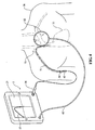
図面を参照すると、図1及び2に示す実施形態において、カテーテル位置案内システム2は、(a)コントローラ又はプロセッサ20(図2)と表示装置22とを支持するハウジング18を有する装置10;(b)ワイヤ、ケーブル、信号データ接続、又は搬送波62によってプロセッサ20に電気的に接続された非侵襲性の移動可能な電磁信号受信機32;(c)電源25;(d)装置10に電気的に接続された、一例を挙げれば、表示装置22にも表示される相対的なカテーテル位置情報を表示するデータ及び/又はグラフィック(図形)37を有する印刷装置又はシリアル回線インターネットプロトコル(slips)のようなハードコピー装置43;及び(e)受信機32と通信し、ワイヤ、ケーブル、コード又は電気的延長コード34によって装置10に動作可能に接続され、次に、プロセッサ20に動作可能に接続されたガイドインサートアセンブリー12(図3)を含む。
1. Catheter Position Guidance System Referring to the drawings, in the embodiment shown in FIGS. 1 and 2, the catheter position guidance system 2 includes (a) a
ここに詳細に開示された一の実施形態において、デバイス32が受信機であることは、十分に理解されるべきであり、ガイドインサートアセンブリーの電磁場ラジエータが患者の体内に位置している。しかしながら、デバイス32は、それぞれ患者の体内に留置された電磁場ラジエータ又は受信素子から信号を受信し、及びそれらに信号を送信するように、互いに独立して動作する信号受信機及び信号送信機を含む。あるいは、デバイス32は、ガイドインサートアセンブリーの一部である、患者の体内に留置された受信素子によって受信される信号を、その患者の体内に送信する送信機を含む。
In one embodiment disclosed in detail herein, it should be appreciated that the
図2に最も良く示されるように、一の実施形態において、システム2は、(a)1又は2以上のコントロールボタン29、タッチスクリーン31(コントロールボタン29のように表示装置22に内蔵される)及び受信機32のような、システム2に入力信号を供給するための複数の入力装置17;(b)受信機32によって受信される信号を放射する電磁場ラジエータ58;(c)機械読み込み可能な指示命令、及び電磁場ラジエータ58によって送信され、受信機32によって受信される信号データを処理し、さらに使用されるガイドインサートアセンブリーの種類及び様々なコントロールボタンの操作又はシステムの動作に必要なタッチスクリーンによる指示を処理するプロセッサ20によって使用される1又は2以上のコンピュータプログラム(例えば、ソフトウェアプログラム30及び複数のアルゴリズム23を含む)を有するメモリデバイス21;及び(d)医療提供者及び電磁場ラジエータ58に接続するための信号送信装置51にカテーテル追跡情報を示す表示装置22、ハードコピー装置43のような複数の出力装置19を備える。表示装置22は、特に限定されるものではないが、液晶ディスプレイ(LCD)、発光ダイオード(LED)ディスプレイ、ブラウン管(CTR)ディスプレイ、又はプラズマスクリーンを含む適当なディスプレイであればよい。
As best shown in FIG. 2, in one embodiment, the system 2 includes (a) one or
医療提供者は、様々なカテーテルの位置決めの用途にシステム2を使用することができる。図3に示す一例において、システム2は、腸内の用途に使用される。ここで、ガイドインサートアセンブリー12の一部70は、患者の鼻72(又は口)を介して留置される。ガイドインサートアセンブリー12の遠位端又は先端60は、図3に示すように、空腸74内における腸内栄養供給法に最も適した位置に留置され、胃の幽門口を介してカテーテルを留置することによってアクセスされ、患者の腸の内部に接近する。医療提供者は、特にカテーテル位置案内システム及びカテーテルを留置しながらカテーテルの遠位端の経路の目安となるディスプレイによる手段に従って体78の胸部76の上に受信機32を置く。特に、表示装置22及びハードコピー装置43は、体78の中のガイドインサートアセンブリーの電磁場ラジエータ58に隣接する先端部分60の位置に関連する情報、さらに経時的にガイドインサートアセンブリー12によって得られる経路の形状に関連する情報を表示する。当然のことながら、システム2は、患者の所定の位置にカテーテルの遠位端を留置することにおいて医師を補助するために、ガイドインサートアセンブリー12の正確な位置又は経路を表示する必要はない。一の実施形態において、表示装置22は、ガイドインサートアセンブリー12の遠位端が、ここに参照される係属中の出願において十分に開示される方法で、人体の構造の解剖学的テンプレートに関する位置を表示する。医療提供者は、腸内栄養供給の準備に空腸74にガイドインサートアセンブリー12の遠位端を適正に留置するために補助となる案内として、画像37を使用する。
The healthcare provider can use the system 2 for various catheter positioning applications. In the example shown in FIG. 3, the system 2 is used for intestinal applications. Here, a
図4に示す他の例では、ガイドインサートアセンブリー12(先の図面で詳述されたものと同じ構造である必要はない)の一部71が、心臓75に至る静脈又は動脈73を通って患者の体78の中に導入される。システム2は、薬剤又は他の液体の送達の準備において、心臓75における所定の空洞に患者の静脈又は動脈73を介してガイドインサートアセンブリー12の一部71を案内することにおいて、医療提供者を補助する。
In another example shown in FIG. 4, a
2.カテーテル
図5に示すように、一の実施形態において、カテーテル50の一例としては、(a)近位端162(図示せず);(b)遠位端164及び(c)外面部を有する本体160を備えるフィーディングチューブを含む。近位端162は、Y−ポートコネクタを通じて流動食をカテーテル50に送り込むためのY−ポートコネクタタイプ(図示せず)のカテーテル分岐部に挿入可能である。一の実施形態において、外面部は、カテーテル50の本体160に沿って間隔をあけて均一に、複数の容量、測定又は単位のための模様を有する(図示せず)。模様は、カテーテル50が体内に留置された深さの見極めにおいてユーザを補助する留置目印として機能する。
2. Catheter As shown in FIG. 5, in one embodiment, an example of a
図5に最もよく示すように、一の実施形態において、カテーテル50の端部のチップ60(用途に適合する様々な構造を有するものであればよい)は、カテーテルの遠位端164に取り付けられる。チップ60は、本体部172と端部176とを有する。本体部172は、通路178と開口部180とを決定する。開口部180は、環状部174と端部176との間に位置する。端部176の先端部177は、曲線的形状を有している。チップ60の開口部180の形状は、開口部180が詰まる可能性が減少するまでの間に、カテーテル50から患者の体内に流動食が流れやすいように構成される。
As best shown in FIG. 5, in one embodiment, a
Y−ポートコネクタ(図示せず)、カテーテル50(フィーディングチューブ)及びチップ60(図1)は、それぞれ、ポリアミド、ポリエチレン、ポリプロピレン、ポリウレタン、シリコン及びポリアクリロニトリルを含む適当なポリマー又はプラスチック部材からなるものであるが、これらに限定されるものではない。カテーテルが必要に応じて使用されるように、電磁場ラジエータを含むガイドインサートアセンブリーが格納されるまでの間に必要である限り、カテーテルは体内に残される。 The Y-port connector (not shown), catheter 50 (feeding tube) and tip 60 (FIG. 1) are each made of a suitable polymer or plastic member including polyamide, polyethylene, polypropylene, polyurethane, silicon and polyacrylonitrile. However, it is not limited to these. The catheter remains in the body as long as necessary until the guide insert assembly including the electromagnetic radiator is retracted so that the catheter can be used as needed.
3.ガイドインサートアセンブリーI
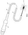
図6〜10に最もよく示すように、大きな内径のカテーテルに最も適合する一の実施形態において、ガイドインサートアセンブリー12は、(a)プロセッサ20(図示せず)に動作可能なように接続された電気コネクタ36;(b)コネクタ36に動作可能なように接続された信号導電ワイヤアセンブリー38(図7A,10);(c)コネクタ36に接続され、この実施形態において信号導電ワイヤアセンブリー38の支持部としての役割を果たす長尺状補剛材(単独で使用される際に、カテーテル50を固定し、位置へのカテーテルの操作を補助するために使用される「スタイレット」として最もよく知られる素子)39;(d)信号導電ワイヤの一部として動作可能であり、信号導電ワイヤアセンブリー38の遠位端に位置する電磁場ラジエータ58(図6,8,10);(e)この実施形態において、長尺状補剛材39の遠位端に接続され、この実施形態において電磁場ラジエータ58の支持部としての役割を果たすインダクタンス増強素子238(図9,10);(f)電磁場ラジエータ58を覆う、又は封入する保護部63(図10);及び(g)この実施形態において長尺状補剛材39の遠位端226を電磁場ラジエータ58(図10)に取り付ける固定部64を含む。管状のカバー部40(図6)は、図1に描かれた実施形態において、ガイドインサートアセンブリー12の残りがカテーテル50内に延びている間のYコネクタまでの信号導電ワイヤアセンブリー38の一部分を覆う。
3. Guide insert assembly I
As best shown in FIGS. 6-10, in one embodiment that best fits a large inner diameter catheter, the
熱収縮材料でアセンブリーを覆い、アセンブリーの部分についてその熱収縮材料が収縮するように熱をかけることによって、コネクタ、長尺状補剛材、信号導電ワイヤ及び電磁場ラジエータを有するガイドインサートアセンブリーを封入することは可能であり、このようにしてアセンブリーに保護カバーを設けることができる。 Enclose the guide insert assembly with connector, elongated stiffener, signal conducting wire and electromagnetic field radiator by covering the assembly with heat shrink material and applying heat so that the heat shrink material shrinks for parts of the assembly It is possible to do this and in this way a protective cover can be provided on the assembly.
他のガイドインサートアセンブリーは、本明細書の後段に同様の見出しで開示される。 Other guide insert assemblies are disclosed under similar headings later in this specification.
4.コネクタ
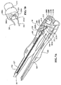
図7Aに最もよく示すように、一の実施形態において、コネクタ36は、電子リード線アセンブリー又はコネクタ36の本体の内部に位置する電子コネクタ180を有する。図7Aに示された実施形態は、複数の固定部を有するが、当然のことながら、他の実施形態において、1つの固定部が、コネクタ36の2つの部分の本体を構成する2つの面186,189(図7A)の間にブロック213をしっかりと位置させる。
4). Connector As best shown in FIG. 7A, in one embodiment, the
図7A,B及び10に最もよく示すように、一の実施形態において、信号導電ワイヤアセンブリー38は、(a)端子206Aに接続された銅線(又は他の適当な低抵抗導線)202のような長尺状の弾性を有する導線の第1の端部206;及び(b)端子212Aに接続された信号導電ワイヤ202の第2の端部212を有する。両端子は、ブロック213を通って縦方向に延伸し、他のコネクタ又は装置10に配置されたプロセッサに直接的に接続するためのソケット206B,212Bをそれぞれ備える。
As best shown in FIGS. 7A, B and 10, in one embodiment, the signal
銅線の端部202A,202Bは、対応する端子206A,212Aにはんだ付け、さもなければ機械的に又は化学的に接続され、又は電気的連続性が銅線と端子との間で維持される限り、コネクタ36の本体の2つの部分の閉成によって、示さない一の実施形態にて達成される圧接処理を含む適切な手段によって取り付けられる。適切な化学的固定手段は、接着剤、化学結合、溶接ボンド及びアセンブリーの他の領域で素子をともに固定するために使用される成形手段からなる群より選ばれる固定手段を含む。
The copper wire ends 202A, 202B are soldered to the
端子とブロック213とを交換可能な他の実施形態において、回路基板は、それぞれの回路基板トラック上に形成された接触部を備える。回路基板は、信号導電ワイヤ202の端部からコネクタ36の本体の近位端に延伸するようにして配置され、装置10に設置されたプロセッサに電気的接続を達成するための適切なコネクタを有する。
In another embodiment in which the terminals and block 213 can be exchanged, the circuit board includes a contact formed on each circuit board track. The circuit board is arranged to extend from the end of the
図7Bには、ブロック213上の付加端子208A,210Aが示され、それらの間に個別抵抗214の形で所定の抵抗値を与えることができる。両端子は、ブロック213を通って縦方向に延伸し、その他のコネクタ又は装置に設置されたプロセッサに直接的に接続するためのソケット208B,210Bをそれぞれ備える。付随する電子装置及びソフトウェアを使用するプロセッサによって決定される抵抗値214は、電磁場ラジエータ58によって放射され、受信機32によって受信される信号を処理する際に、所定のファクターが考慮されるように、プロセッサに接続されたガイドインサートの種類をプロセッサに示す。それらの接続にわたって測定される抵抗量は、コネクタが固定されたガイドインサートアセンブリーの種類に特有である。抵抗測定は、コネクタが使用されるときにカテーテル位置案内システムによって行われる。このようなシステムは、そのときに使用される様々なガイドインサートを自動的に知ることができる。
FIG. 7B shows
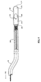
図6には、コネクタ36と、電磁場ラジエータ58が位置する遠位端に補剛タイプのワイヤを有するガイドインサートアセンブリー12とが示されている。
FIG. 6 shows the
図8は、中心静脈カテーテルに好適な本発明の一実施形態における電磁場ラジエータの斜視図である。コネクタ36は、装置10と、ガイドインサートアセンブリー12の遠位端に電磁場ラジエータを有するとともに、その長さにわたってカバー400を有する信号導電ワイヤ202から形成されたガイドインサートアセンブリー12とを介して、プロセッサに直接取り付け可能である。
FIG. 8 is a perspective view of an electromagnetic field radiator in one embodiment of the present invention suitable for a central venous catheter. Via the
信号導電ワイヤアセンブリー39の遠位端204は、電磁場ラジエータ58を形成する。
The
図10に示す実施形態において、銅線の遠位端204は、電磁場ラジエータ58を形成するコイル配置にて形成される。銅線は、図9及び10に示す、通常の円筒型の低透磁性材料からなる巻型に巻き付けられる。電磁場ラジエータ58は、銅線の一部分で他の実施形態においてインダクタンス増強素子238である巻型を包み込むことによって製造される複数の螺旋状構造物から形成される。単線は、コイル注意深く配列した2つの層にて巻型に巻き付けられる。そのような方法で製造されたコイルの断面形状が図10に描かれている。コイルは、約0.02mmの外径及び約0.035mmの長さを形成する。
In the embodiment shown in FIG. 10, the
図7A及び10を参照すると、信号導電ワイヤ202は、この実施形態において、長尺状補剛材39に巻き付けられている。信号導電ワイヤの巻き付きが、その長さにわたって信号の放射を取り消し、又は最小限に抑え、図7A,B及び10に示されるように、長尺状補剛材39に巻き付く構造217を有する。一の実施形態において、信号導電ワイヤは、その長さにわたって1mにつき約500の巻き付きを有するが、信号導電ワイヤアセンブリー38は、適当な巻き付き数を含むものであればよく、1mにつき600の巻き付き数を有するのが適当である。したがって、手持ち受信機32は、信号導電ワイヤアセンブリー38によって発生した電磁場から生じる信号干渉がもしあったとしても、それを受信することがない。
With reference to FIGS. 7A and 10, the
5.長尺状補剛材
一の実施形態において、開示されたコネクタは、いかなる種類のガイドインサートにも使用し得るが、図7Aに示すように、コネクタは、素子を固定するワイヤを有するガイドインサートとともに使用するものとして示される。長尺状補剛材39は、部分228に屈曲部を有する。長尺状補剛材39は、例えば、スチールワイヤ等の鉄鋼材からなるのが好ましいが、他の適当な材料からなるものであってもよく、患者の体内の位置にカテーテルを留置する間、医療提供者のために、カテーテルの端部の操作を補助するためのスタイレットのように作動するのが好ましい。長尺状補剛材39の中心部分228は、この実施形態において、コネクタ36の固定部194の回りに巻き付けられ、補剛材のワイヤは、それ自身の回りに巻き付けられ、巻き付き(ツイスト)構造234を形成する。他の実施形態において、その2つの半分が互いに固定されたら、部分228の屈曲部は、コネクタにてワイヤを維持するのに十分である。
5. Elongate Stiffener In one embodiment, the disclosed connector can be used with any type of guide insert, but as shown in FIG. 7A, the connector is coupled with a guide insert having wires to secure the element. Shown for use. The
ワイヤの捻じれ構造234は、長尺状補剛材39の剛性を増加させる。長尺状補剛材は、使用され、一の実施形態において電磁場ラジエータ58を支持する巻型に接続されるカテーテルの隣接する遠位端を終端処理する。それ故に、上記長尺状補剛材は、単線から中心部分228を形成する。しかしながら、他の実施形態において、長尺状補剛材は、互いに巻き付けられ、機械的にではあるが非導電的にコネクタ本体及び電磁場ラジエータのそれぞれに互いの端部を接続した2つの分離するワイヤからなるものであってもよい。
The
6.電磁場ラジエータ
図9,10に最もよく示すように、一の実施形態において、電磁場ラジエータ58は、信号導電ワイヤの複数の螺旋巻きによって形成される。一の実施形態において、装置10は、信号導電ワイヤを通じて交流を送り、使用時に、カテーテル50の遠位端に設けられた電磁場ラジエータ58から、好ましくはそれのみから放射される電磁場の放射を引き起こす。示された実施形態は、電磁場ラジエータ58としてコイルからなるものであるが、電磁場ラジエータ58が、その電磁場を作り出すための電磁エネルギー又は電磁場を生成し又は生産する代替メカニズム又は装置からなるものであると理解すべきである。
6). Electromagnetic Field Radiator As best shown in FIGS. 9 and 10, in one embodiment, the
一の実施形態において、電磁場ラジエータ58は、例えば、永久磁石、常伝導磁石、超伝導磁石等の低透磁性素子(図9,10)238からなるものであり、アモルファス磁性材料タイプ又はその他の適当な材料からなるものであればよい。
In one embodiment, the
一の実施形態において、インダクタンス増強素子238は、フェライト特性を有する筒状素子を含む。一の実施形態において、そのようなフェライト特性は、特に限定されるものではないが、フェライト酸化物と他の酸化物との適当な複合物や、あるいはそれぞれ高透磁性を有する適当な強磁性化合物を含む。インダクタンス増強素子283は、電磁場ラジエータ58から受信機32に、電磁フラックス、電磁エネルギー又は電磁場(図9)258を増加させ、又は追加する(図示せず)。一の実施形態において、インダクタンス増強素子238は、筒状であり、他の実施形態においてはロッド形状である。フェライト素子がインダクタンス増強素子として使用されるとき、フェライト元素によって生成される電磁場は、コイル246,248によって生成される電磁場を増大させ、これにより、受信機32によって受信可能な信号を強化する。当然のことながら、適した数のコイル及び適した交流が使用され、電磁場ラジエータによって放射された電磁場の強さの一つの要素が、コイルの数、並びに電流のレベル及び周波数などの多くの他の因子に依存する。
In one embodiment, the
図10に最もよく示されるように、一の実施形態において、インダクタンス増強素子238は、開口部244を決定する外面240と内壁242を含む形状を有する。当然のことながら、開口部244は、コア又はインダクタンス増強素子238までずっと延伸する必要はない。信号導電ワイヤ202は、最外面240を覆い、コイルを形成する。上述したように、コイルは複数の螺旋からなる。
As best shown in FIG. 10, in one embodiment, the
螺旋構造物は、均一のパターンを有するのが好ましい。一の実施形態において、各個別の螺旋構造物252は、対応する下にある螺旋構造物250と同一のX軸上の位置に配置される。代わりの実施形態において、各螺旋構造物252は、下にある各螺旋構造物250から偏心した位置に配置され、各実施形態は、均一なパターンの螺旋構造物を形成する。螺旋構造物の均一のパターン(特に前者のパターン)は、コイルによって生成される電磁場のベクトルの和を増加させる。当然のことながら、コイルから電磁場の照射を促進する螺旋構造物250,252のいかなる均一なパターンをも使用することができる。信号導電ワイヤのポリマーコート218の厚さは、比較的薄いものである。したがって、信号導電ワイヤは、互いに相対的に接近し、インダクタンス増強素子238の回りに巻き付けられる。これにより、空間効率が増加する。空間効率は、特に、様々なカテーテル又は信号導電ワイヤキャリア(この明細書にてさらに後述する)を収納するのに十分に小さくなるために、コイルの外径を最小に維持する。
The spiral structure preferably has a uniform pattern. In one embodiment, each individual
被覆剤又は保護剤63は、コイル及びインダクタンス増強素子238を封入し又は覆う。通常の使用において、チューブアセンブリーが体内でカテーテル50内にある期間がわずかであったとしても、この保護剤63は、コイル246,248を流体から保護する。特に限定されるものではないが、ポリマー及び紫外線抵抗性接着剤を含む防液物質又はこの目的にとって好適な防液剤が、コイルを覆い又は封入するために使用される。コーティング表面の最遠位外表面は、カテーテルが留置される患者の体の内部に与えるダメージを最小限にし又は未然に防ぐために、電磁場ラジエータ58アセンブリーの外表面の通常の形状のように、滑らかに作られる。これは、ポリマー材料製のカテーテルにおいてあまり適切ではなく、シリコン製のカテーテルにおいて可能である。
A coating or
固定部64は、インダクタンス増強素子238の内壁242の内側の長尺状補剛材39の部分225,227に取り付けられる。そのため、信号導電ワイヤに力が実質的に移ることなく、ユーザのカテーテル及びガイドインサートアセンブリーの挿入力が、長尺状補剛材39からインダクタンス増強素子238に伝わる。非導電性接着剤、エポキシ又は他の適当な固定部のいずれの種類であっても、内壁242に長尺状補剛材39を固定するのに使用することができる。インダクタンス増強素子又はコイルに長尺状補剛材を固定する他の処理は、上述した固定部の代わりに、又は付加的に使用される。
The fixing
操作中において、装置10が電磁場ラジエータ(この実施形態においてはコイル)に電流を送るとき、コイルは、非侵襲性の受信機32によって検出可能な信号又は電磁場258を放射する。図9に示す一例において、信号の1サイクル間、電磁場258は、コイルに近接する端部255から、すぐ近くの空気及び他の材料を通して流れ、コイルへの電流の流れが適当な方向にあるときに、コイルの遠位端257に再入する。インダクタンス増強素子238内において、電磁場258は、遠位端からその素子の近位端に流れ戻る。したがって、信号導電ワイヤが、インダクタンス増強素子についてコイルの形状を有するとき、これらの形状が、インダクタンス増強素子238なしで信号導電ワイヤ又はコイルの直線部分によって生産された電磁場の上に、増強された電磁場258を作り出す。当然のことながら、電磁場258の磁性部分は、コイルを通る電流方向に極性依存性を有する。
In operation, when the
7.信号導電ワイヤ
図11は、特定の用途のガイドインサートアセンブリーの一部分を示すものであり、長尺状補剛材39は、一組のツイストワイヤ302,304と、それらの上に巻き付けられる、カバー部500を有する信号導電ワイヤアセンブリー38を含む。図11に示すイラストレーションには、ワイヤ間の間隙が明白に描かれているが、ワイヤ間の間隙は実際の巻き線には存在せず、むしろ図12に示すような空間的関係を有する。
7). Signal Conductive Wire FIG. 11 shows a portion of a guide insert assembly for a particular application, with an
信号導電ワイヤが単線であるため、導電ワイヤが長尺状補剛材と同様にそれ自身に巻き付けられる、図11に示す構成に仕上げるための方法で、長尺状補剛材ワイヤ上に巻き付けられる。示した結果を達成するいくつかの方法があるが、一の実施形態における巻き線は、最初に信号導電ワイヤ202のほぼ中央で電磁場ラジエータ58を形成し、それから、長尺状補剛ワイヤの間の一の溝に信号導電ワイヤの位置の半分を巻き付け、コネクタに至る長尺状補剛材の長さにわたる他の溝に信号導電ワイヤの一の半分を巻き付ける。このように、信号導電部がワイヤを含み、ワイヤは高分子塗膜を有し、ワイヤの端部は、それぞれコネクタ36のコンタクト部材に動作可能に接続される。そして、信号導電ワイヤは、その長さにわたり自身に巻き付く(信号導電ワイヤがツイストした補剛ワイヤアセンブリーに巻き付いているにせよ、信号導電ワイヤが自身に巻き付いて、自身に接触する必要はない)。
Since the signal conducting wire is a single wire, the conducting wire is wound on itself in the same manner as the elongated stiffener, and is wound on the elongated stiffener wire in a manner to finish the configuration shown in FIG. . Although there are several ways to achieve the results shown, the windings in one embodiment first form an
説明したような信号導電ワイヤの捻れは、信号導電ワイヤアセンブリー38の長尺状部分からの電磁場の放射を最小限にするのに役立つ。図11,12を参照すると、電磁場ラジエータ58に搬送される電流は、ワイヤ308と効果的に平行し、反対方向に電流を搬送する一のワイヤ306で搬送されるため、各電流によって生成される電磁場は、当業者によって理解されるように、実質的に互いに相殺されて流れる。
Twisting of the signal conducting wire as described helps to minimize electromagnetic field radiation from the elongated portion of the signal
そのような配置は、相互に直接的に反対の電流によって生成される電磁場を設けるのに役立つ。図12は、ガイドインサートアセンブリー12のA−A線断面図を示し、互いに平行する長尺状補剛材ワイヤ302,304及び信号導電ワイヤ306,308の断片を示す。
Such an arrangement serves to provide an electromagnetic field generated by currents directly opposite each other. FIG. 12 shows a cross-sectional view of the
図12はまた、熱収縮性材料、ポリウレタンによって提供されるカバー部500に適合する形状、又は非導電的であり、医学的応用分野において使用可能な材料に適合する他の形状を示す。
FIG. 12 also shows a heat shrinkable material, a shape that conforms to the
8.ガイドインサートアセンブリーII及びIII
これまで詳細に説明したガイドインサートアセンブリーのタイプは、スタイレットに非常に類似するが、信号導電ワイヤ及び電磁場ラジエータもまた移送する、ワイヤタイプの長尺状補剛材を含むタイプのものである。長尺状補剛材の他のタイプは、カテーテルに酷似し、いくつかの実施形態においてカテーテルと同一の材料で作られるチューブである。
8). Guide insert assembly II and III
The type of guide insert assembly described in detail so far is of a type that includes a wire-type elongated stiffener that is very similar to a stylet but also carries a signal conducting wire and an electromagnetic field radiator. . Another type of elongate stiffener is a tube that closely resembles a catheter and in some embodiments is made of the same material as the catheter.
長尺状補剛材のようなチューブが使用されると、信号導電ワイヤ及び電磁場ラジエータは、ガイドインサートアセンブリーになるようにチューブ内に搬送される。そのカテーテル内への挿入は、カテーテルを硬化し、医療提供者が位置にカテーテルを操作するのをより容易にし、カテーテル位置案内システムと併用する際に、仕事をより容易にし、患者をより安全にする。 When a tube such as an elongated stiffener is used, the signal conducting wire and the electromagnetic field radiator are conveyed into the tube to become a guide insert assembly. Its insertion into the catheter stiffens the catheter, makes it easier for healthcare providers to manipulate the catheter into position, makes work easier and safer for patients when used with a catheter position guidance system. To do.
長尺状補剛材チューブの外径は、使用中に留置されるのに最も適しているカテーテルの大きさを決定する。いくつかのカテーテルは、1を超えるルーメン(近位端から遠位端に流動食を通す通路)を有することがなく、ガイドインサートアセンブリーチューブは、内部に固定することができる必要があり、また、十分な摩擦干渉なくしてルーメンから引き抜くことができる必要がある。管腔の最も小さい内径としては、0.05mmと同様に小さければよく、チューブのサイズが外径と同一又はそれよりも小さくなければならない。さらにまた、電磁場ラジエータの外径は、そのような実施形態のガイドインサートアセンブリーが作り出されるとき、ガイドインサートアセンブリーチューブ内にフィットするように小さくなければならない。 The outer diameter of the elongate stiffener tube determines the size of the catheter that is most suitable for placement during use. Some catheters do not have more than one lumen (passage through which liquid food passes from the proximal end to the distal end), the guide insert assembly tube must be able to be secured internally, and It must be able to be pulled out of the lumen without sufficient frictional interference. The smallest inner diameter of the lumen may be as small as 0.05 mm, and the size of the tube must be the same as or smaller than the outer diameter. Furthermore, the outer diameter of the electromagnetic field radiator must be small to fit within the guide insert assembly tube when the guide insert assembly of such an embodiment is created.
さらにまた、チューブを作る材料の種類もチューブの硬さを決定する。例えば、チューブ材料が高分子化合物からなる群より選ばれる場合、その材料がシリコン化合物からなる群より選ばれる場合よりも硬くさせる可能性がある。これらの2種類の材料は、単に使用可能な材料というだけではない。たとえチューブ材料がカテーテルと同一であったとしても、患者に挿入されるときに、チューブがカテーテルを硬化しやすい範囲内であって、チューブの用途の範囲内で使用される。 Furthermore, the type of material from which the tube is made also determines the hardness of the tube. For example, when the tube material is selected from the group consisting of polymer compounds, it may be harder than when the material is selected from the group consisting of silicon compounds. These two types of materials are not just usable materials. Even if the tube material is the same as the catheter, it is used within the scope of the tube application, as long as the tube is easy to cure the catheter when inserted into the patient.
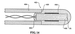
図13,14は、ガイドインサートアセンブリーのようなチューブの実施形態を示す。図13は、電磁場ラジエータ58は、チューブ500内に完全に留置され、非導電性接着剤402又はチューブの端部を封止し、チューブ500の遠位端に隣接する電磁場ラジエータ58の位置を固定するための類似の化合物で、その遠位端(使用時)に栓をされる、ガイドインサートアセンブリー401の構造を示す。電磁場ラジエータ58は、チューブ500の外面に構成され、電磁場ラジエータを形成するために使用する信号導電ワイヤは、あらかじめチューブ500を通過させるか、電磁場ラジエータの形成の後にチューブを通過させる。電磁場ラジエータ58、及び非導電性接着剤又は類似の化合物の適用は、チューブ500の遠位端から引き戻され、又はそこに設置され、チューブ500の遠位端に隣接する位置に固定される。
Figures 13 and 14 show an embodiment of a tube such as a guide insert assembly. FIG. 13 shows that the
また、電磁場ラジエータ58は、ラジエータコイルが非常に小さい径を有するときに、コイルのための巻型としてのインダクタンス増強材料を、たいがいは有している。
Also, the
信号導電ワイヤは、信号導電ワイヤの長尺状部分からの電磁的放射が最小限になるアセンブリーを形成するために、それ自身で巻き付いているのが好ましい。 The signal conducting wire is preferably wrapped by itself to form an assembly that minimizes electromagnetic radiation from the elongated portion of the signal conducting wire.
図14は、電磁場ラジエータ58がチューブ404の外側に位置するガイドインサートアセンブリー403と同様なチューブのさらなる実施形態を示す。そのような配置は、チューブ404の外径と厳密に合致するために電磁場ラジエータコイルとカバー材料406との最大外径を許容する。カバー材料406は、チューブ404の遠位端409で巻型408(インダクタンス増強材料であればよく、同一及び対称の、コイルによって覆われない部分とコイルによって覆われる部分とを有するもの)の端部を滑らかな外形で固定し、電磁場ラジエータコイルを露出させることなく封入する非導電性接着剤又は類似する化合物であればよい。
FIG. 14 shows a further embodiment of a tube similar to the
図15は、抹消静脈穿刺(PICC)型カテーテル410に挿入されたガイドインサートアセンブリー405(図14)のようなチューブの使用の図を示す。
FIG. 15 shows a diagram of the use of a tube such as a guide insert assembly 405 (FIG. 14) inserted into a peripheral venipuncture (PICC)
説明した各ガイドインサートアセンブリーは、それらの用途に適したサイズに設定されるものであり、通常のバリエーションにおいて、それらは特に大人用のサイズや、大人と比較して子供のより小さい体及び通路に適合するために、長さと同様により小さい外側及び内側の局面のカテーテルを使用する小児科用途において要求される小児への使用において、より小さいサイズ(長さと同様に外径)が設定される。 Each of the described guide insert assemblies is sized to suit their application, and in normal variations, they are especially for adults and smaller bodies and passages for children compared to adults. In order to meet the requirements, smaller sizes (outer diameter as well as length) are set for pediatric use as required in pediatric applications using smaller outer and inner aspect catheters as well as length.
9.カテーテル位置案内システムとガイドインサートアセンブリーとの使用
作動中に、受信機32は、人の体内の電磁場ラジエータ58によって生成された電磁場又は信号258を検出する。プロセッサ20は、表示装置22及びハードコピー装置43に、カテーテル留置処理において医療提供者を補助する画像37を表示させる。
9. Use of the Catheter Position Guidance System and Guide Insert Assembly During operation, the
ほんの一例として図1に示すように、システム2は、最初に、カテーテル50の長さを決定することによって使用される。
As shown by way of example only in FIG. 1, the system 2 is used by first determining the length of the
ガイドインサートアセンブリーの使用のいくつかの実施形態において、カテーテルの長さは厳密であり、ガイドインサートアセンブリーの対応する長さが測定される。このように、その2つのアイテムは、既に設置された特定のカテーテルに適した、事前に適合されたガイドインサートアセンブリーが供給され、装置10に、又は本明細書において前述し、図7Aに示したタイプの中間のコネクタに直接的に接続される状態にある。 In some embodiments of use of the guide insert assembly, the length of the catheter is exact and the corresponding length of the guide insert assembly is measured. As such, the two items are supplied with a pre-adapted guide insert assembly suitable for a particular catheter already installed, as shown in FIG. It is in a state where it is directly connected to an intermediate connector of another type.
現在使用されているほとんどのカテーテルにおいて、カテーテルの長さを患者に合わせる必要があり、最初に、患者の表面で測定された測定値、及びそのような機器の使用のために定められる手順からの手引きによって、必要とされるカテーテルの長さを推測する。カテーテルは、適するようにその遠位端又は近位端にて切断される。 For most catheters currently in use, the length of the catheter needs to be adapted to the patient, first from measurements measured on the patient's surface, and from procedures established for the use of such devices. Guidance is made on the required catheter length by guidance. The catheter is cut at its distal or proximal end as appropriate.
ガイドインサートアセンブリーの使用のいくつかの例では、図16に示すように腸内又は非経口の栄養補給のために人体にカテーテル50を留置する前に、ユーザ又はアセンブラは、カテーテル50内に、遠位端に電磁場ラジエータ58を備えるガイドインサートアセンブリー12(この例においてガイドインサートアセンブリーは、チューブ状の長尺状補剛材を有する,図14参照)を留置する。ある配置において、電磁場ラジエータ58は、図15に断面図で詳細に示すように、カテーテルのチップ60に隣接して位置される。
In some examples of use of the guide insert assembly, prior to placing the
カテーテル内のガイドインサートアセンブリー12の長さを固定することは、効果的であり、これは、一の実施形態において、ガイドインサートを通過し、トゥヒーボーストアダプターの操作によってカテーテルに相対的にロックされるトゥヒーボーストアダプター520に接続されたカテーテルの近位端上のルアーロック接続部510で済ませることができる。
It is advantageous to fix the length of the
それから、医療提供者は、患者の胸の上に受信機32を置き、体内にカテーテル50を挿入する。ここで留意すべきは、ガイドインサートアセンブリー16が、患者の体内にカテーテルを留置する間にだけ、カテーテル内に必要とされることである。ガイドインサートアセンブリーは、トゥヒーボーストから解除され、一度留置が達成されると取り除かれる。
The health care provider then places the
それから、カテーテルは、腸内の例において、胃又は他の消化管の内部における要求される位置に栄養物を運ぶために使用される。動脈又は静脈を含む用途のためにカテーテルは第1に使用されるが、これに限定されるものではなく、しばしば、体の心臓血管系で体の必要な位置に薬剤を運ぶためにも使用される。 The catheter is then used to deliver nutrients to the required location within the stomach or other gastrointestinal tract in the intestine example. Catheters are primarily used for applications involving arteries or veins, but are not limited to this, and are often used to deliver drugs to the body's cardiovascular system where it is needed. The
カテーテルが留置されると、表示装置22は、人体内の所望の位置にカテーテルの先端60を案内するのにユーザを補助する画像37を表示する。それらの画像は、X線と同様ではなく、画像イメージは、医療提供者へのカテーテルの遠位端の位置の表示のみ役立つ表示のみである。カテーテル50が所望の位置に一度留置されると、ユーザは、カテーテル50の位置が維持される間、ガイドインサートアセンブリー12を取り除く。それから、管状のカバー部40は、コネクタ及びもし使用するならY−ポートから除去され、廃棄される。
Once the catheter is in place, the
それから、例えば、ユーザは、薬物療法のため体内に液体を導入するために、医薬及び栄養物移送管をY−ポートコネクタ44の適当なポートに取り付ける。Y−ポートコネクタの使用は、そのような栄養補給又は薬物の送達のために知られている。
Then, for example, the user attaches a medication and nutrient transfer tube to the appropriate port of the Y-
他の実施形態において、当然のことながら、アセンブラは、各カテーテルを測定してもよいし、各カテーテルが長すぎるとか短すぎるとかいうことを無視してもよいが、本発明のガイドインサートアセンブリーは、ラジエータ位置制御装置を含む必要がない。また、当然のことながら、他のアセンブリープロセス及びメカニズムは、カテーテル、特に先端60の部分と相対的に電磁場ラジエータ58の適した留置を制御するために使用されてもよい。
In other embodiments, it will be appreciated that the assembler may measure each catheter or ignore that each catheter is too long or too short, but the guide insert assembly of the present invention is It is not necessary to include a radiator position control device. It should also be appreciated that other assembly processes and mechanisms may be used to control the proper placement of the
同様に当然のことながら、図1に絵を用いて示されたアセンブリー、本発明のガイドインサートアセンブリー及びカテーテル位置案内システムは、様々なカテーテル、カテーテル処置及びカテーテルの用途において使用することができる。これらの処置は、消化管、心血管系、又は人体の他の部分の治療を含んでもよい。これらの処置は、医師、臨床医、医師助手(PA)、看護士、又は他の医療提供者による人間の治療を含んでもよい。追加的に、これらの処置は、獣医、研究者等によるその他の哺乳動物及び動物の治療を含んでもよい。 Similarly, it will be appreciated that the assembly illustrated pictorially in FIG. 1, the guide insert assembly and catheter position guidance system of the present invention can be used in a variety of catheters, catheter procedures and catheter applications. These treatments may include treatment of the digestive tract, cardiovascular system, or other parts of the human body. These procedures may include human treatment by a physician, clinician, physician assistant (PA), nurse, or other health care provider. In addition, these treatments may include treatment of other mammals and animals by veterinarians, researchers, and the like.
一の実施形態において、本発明は、カテーテル位置案内システムのガイドインサートアセンブリーのための電磁場ラジエータを含む。電磁場ラジエータは、カテーテル留置処置行うにあたりユーザを補助するために、システムの他の要素と併用される。また、電磁場ラジエータは、システムの性能を向上させるインダクタンス増強素子を備える。したがって、カテーテル位置案内システムと併用される電磁場ラジエータは、薬物療法の向上を提供する。 In one embodiment, the present invention includes an electromagnetic field radiator for a guide insert assembly of a catheter position guidance system. The electromagnetic field radiator is used in conjunction with other elements of the system to assist the user in performing the catheter placement procedure. The electromagnetic field radiator also includes an inductance enhancing element that improves system performance. Thus, an electromagnetic field radiator used in conjunction with a catheter position guidance system provides improved drug therapy.
当然のことながら、ここに開示した好適な実施形態の様々な変更及び改良は、当業者にとって明らかであろう。そのような変更及び改良は、本発明の精神及び範囲から逸脱するものではなく、目的とする効果を損なうものではない。したがって、そのような変更及び改良は、添付の請求の範囲によってカバーされていることが意図される。 Of course, various changes and modifications to the preferred embodiments disclosed herein will be apparent to those skilled in the art. Such changes and modifications do not depart from the spirit and scope of the present invention and do not impair the intended effect. Accordingly, such modifications and improvements are intended to be covered by the appended claims.
Claims (50)
前記カテーテルに挿入したときに前記カテーテルの前記遠位端に隣接する第1の端部及び遠位端を有し、挿入された際にカテーテルを硬化するための長尺状補剛材と、
その2つの端部によって前記プロセッサに接続可能であり、前記長尺状補剛材の全長に沿った屈曲部を形成するとともに、さらに前記長尺状補剛材の遠位端に隣接する電磁場ラジエータを形成する信号導電ワイヤと
を備え、
前記長尺状補剛材の遠位端が、前記電磁場ラジエータに非導電的に接続されている、ガイドインサートアセンブリー。 A guide insert assembly for use with a catheter having a distal end inserted into the body and a catheter position guidance system having a processor comprising:
An elongate stiffener having a first end and a distal end adjacent to the distal end of the catheter when inserted into the catheter and for curing the catheter when inserted;
An electromagnetic field radiator that is connectable to the processor by its two ends, forms a bend along the entire length of the elongated stiffener, and is adjacent to the distal end of the elongated stiffener A signal conducting wire forming
A guide insert assembly, wherein a distal end of the elongated stiffener is non-conductively connected to the electromagnetic field radiator.
前記第1及び第2のセグメントが相互に巻き付くようにし、前記長尺状補剛材の第1の端部と遠位端との間の少なくとも一部にツイストアセンブリーを形成する、請求項1に記載のガイドインサートアセンブリー。 The elongate stiffener forms a first segment and a second segment;
The first and second segments wrap around each other to form a twist assembly at least in part between the first end and the distal end of the elongated stiffener. The guide insert assembly according to claim 1.
前記信号導電ワイヤの一部が、前記外面の周囲を包み込んで第1のコイル層及び第2のコイル層を形成し、
前記第1及び第2のコイル層が、複数の螺旋構造物を有し、
前記第2のコイル層の螺旋構造物が、前記第1のコイル層の螺旋構造物に対応して一様にパターン化されている、請求項5に記載のガイドインサートアセンブリー。 The inductance enhancing element has an outer surface and an inner wall defining an opening;
A portion of the signal conductive wire wraps around the outer surface to form a first coil layer and a second coil layer;
The first and second coil layers have a plurality of helical structures;
The guide insert assembly of claim 5, wherein the second coil layer helical structure is uniformly patterned corresponding to the first coil layer helical structure.
上面部と、底面部と、回路基板と、前記上面部を前記底面部に取り付ける少なくとも1つの締結部とを有し、前記回路基板が、前記上面部と前記底面部との間に位置し、複数のコンタクト部材を有し、当該複数のコンタクト部材が前記回路基板の一部に広がり、当該複数のコンタクト部材が前記プロセッサと動作可能に接続可能であるコネクタ部;
高分子塗膜を有するワイヤを含み、前記ワイヤの端部が前記回路基板の各コンタクト部材に動作可能に接続し、前記ワイヤがその長さにわたってそれ自身に巻き付く信号導電部;
第1の端部及び第2の端部を有する長尺状補剛材アセンブリーであって、前記長尺状補剛材の第1の端部が前記コネクタ部の一部に接続されて第1のセグメント及び第2のセグメントを形成し、前記第1及び第2のセグメントが互いに巻き付き、前記信号導電部のワイヤアセンブリーが前記長尺状補剛材に巻き付く、長尺状補剛材アセンブリー;
開口部を決定する外面部及び内壁部を有し、前記信号導電ワイヤの一部が、前記外面部の周囲を包み込んで少なくとも1つのコイルを形成し、当該コイルが複数の螺旋構造物を有するインダクタンス増強素子;
前記インダクタンス増強素子及び少なくとも1つのコイルを封入する保護材;及び
前記長尺状補剛材の第2の端部の一部と前記インダクタンス増強素子の開口部内のインダクタンス増強素子との結合部
を備える、ガイドインサートアセンブリー。 A guide insert assembly for use with a catheter position guidance system having a processor comprising:
An upper surface portion, a bottom surface portion, a circuit board, and at least one fastening portion for attaching the upper surface portion to the bottom surface portion; and the circuit board is located between the upper surface portion and the bottom surface portion, A connector portion having a plurality of contact members, the plurality of contact members extending over a portion of the circuit board, and the plurality of contact members being operatively connectable to the processor;
A signal conducting portion comprising a wire having a polymer coating, wherein the end of the wire is operatively connected to each contact member of the circuit board, and the wire wraps around itself over its length;
A long stiffener assembly having a first end and a second end, wherein a first end of the long stiffener is connected to a part of the connector portion to form a first end. And a second segment, the first and second segments are wound around each other, and the wire assembly of the signal conducting portion is wound around the long stiffener. ;
An inductance having an outer surface portion and an inner wall portion that determine an opening, a part of the signal conductive wire wraps around the outer surface portion to form at least one coil, and the coil has a plurality of helical structures Enhancement element;
A protective material enclosing the inductance enhancing element and at least one coil; and a coupling portion between a part of the second end of the elongated stiffener and the inductance enhancing element in the opening of the inductance enhancing element. , Guide insert assembly.
前記プロセッサに動作可能に接続された複数のコンタクト部材を有するコネクタ部;
前記コネクタ部に接続された少なくとも1つのワイヤを有する信号導電部;
第1の端部及び第2の端部を有し、前記第1の端部が前記コネクタ部に接続された長尺状補剛材;及び
前記信号導電部の遠位端に動作可能に形成され、前記長尺状補剛材の第2の端部に動作可能に接続された電磁場ラジエータを備え、
前記電磁エネルギーラジエータが、前記受信機によって検出可能な電磁場を生成し、前記受信機が、前記電磁場に基づいて前記プロセッサに信号を通信し、前記表示装置に表示させる処理をし、前記信号に基づく少なくとも一部のカテーテル情報のグラフィック表示を可能にする、ガイドインサートアセンブリー。 A guide insert assembly for use with a catheter position guidance system having a processor in communication with a display device and a receiver comprising:
A connector portion having a plurality of contact members operably connected to the processor;
A signal conducting portion having at least one wire connected to the connector portion;
An elongate stiffener having a first end and a second end, wherein the first end is connected to the connector; and operably formed at a distal end of the signal conducting portion An electromagnetic field radiator operatively connected to the second end of the elongated stiffener,
The electromagnetic energy radiator generates an electromagnetic field that can be detected by the receiver, and the receiver communicates a signal to the processor based on the electromagnetic field and causes the display device to display the signal. Based on the signal A guide insert assembly that allows a graphical display of at least some catheter information.
前記第1及び第2のセグメントが、相互に巻き付くことで、ツイストアセンブリーを形成し、
各信号導電ワイヤが、前記長尺状補剛材のツイストアセンブリーの一部に巻き付く、請求項20に記載のガイドインサートアセンブリー。 The elongate stiffener forms a first segment and a second segment;
The first and second segments wrap around each other to form a twist assembly;
21. The guide insert assembly of claim 20, wherein each signal conducting wire wraps around a portion of the elongated stiffener twist assembly.
前記プロセッサに動作可能に接続された少なくとも1つのワイヤを有する信号導電部;
第1の端部及び第2の端部を有し、前記第1の端部が前記信号導電部に対応して固定されてなる長尺状補剛材;
前記長尺状補剛材の第2の端部に隣接し、前記信号導電部に接続された電磁場ラジエータ;及び
前記長尺状補剛材の第2の端部の一部と前記電磁場ラジエータとの間の結合部
を備える、ガイドインサートアセンブリー。 A guide insert assembly for use with a catheter position guidance system having a processor comprising:
A signal conductor having at least one wire operably connected to the processor;
A long stiffener having a first end and a second end, the first end being fixed in correspondence with the signal conducting portion;
An electromagnetic field radiator adjacent to the second end of the elongated stiffener and connected to the signal conducting portion; and a portion of the second end of the elongated stiffener and the electromagnetic field radiator; A guide insert assembly comprising a joint between.
前記プロセッサに動作可能に接続された複数のコンタクト部材を有するコネクタ部;
前記コネクタ部に接続された少なくとも1つのワイヤを有する信号導電部;
第1の端部及び第2の端部を有し、前記第1の端部が前記コネクタ部に接続された長尺状補剛材;及び
前記信号導電部の遠位端に動作可能に形成され、前記長尺状補剛材の第2の端部に動作可能に接続された電磁場ラジエータを備え、
前記電磁場ラジエータが、前記受信機によって検出可能な電磁場を生成するように作動し、前記受信機が、前記電磁場に基づいて前記プロセッサに信号を通信し、前記表示装置に表示させる処理をし、前記信号に基づく少なくとも一部のカテーテル情報のグラフィック表示を可能にする、ガイドインサートアセンブリー。 A guide insert assembly for use with a catheter position guidance system having a processor in communication with a display and a receiver comprising:
A connector portion having a plurality of contact members operably connected to the processor;
A signal conducting portion having at least one wire connected to the connector portion;
An elongate stiffener having a first end and a second end, wherein the first end is connected to the connector; and operably formed at a distal end of the signal conducting portion An electromagnetic field radiator operatively connected to the second end of the elongated stiffener,
The electromagnetic field radiator operates to generate an electromagnetic field detectable by the receiver, the receiver communicates a signal to the processor based on the electromagnetic field, and causes the display device to display, and A guide insert assembly that allows a graphical display of at least some catheter information based on the signal.
Applications Claiming Priority (3)
| Application Number | Priority Date | Filing Date | Title |
|---|---|---|---|
| US64417905P | 2005-01-14 | 2005-01-14 | |
| AU2005900142A AU2005900142A0 (en) | 2005-01-14 | Guiding insert assembly for a catheter used with a catheter position guidance system | |
| PCT/AU2006/000027 WO2006074510A1 (en) | 2005-01-14 | 2006-01-12 | Guiding insert assembly for a catheter used with a catheter position guidance system |
Publications (2)
| Publication Number | Publication Date |
|---|---|
| JP2008526390A true JP2008526390A (en) | 2008-07-24 |
| JP2008526390A5 JP2008526390A5 (en) | 2009-04-02 |
Family
ID=36677301
Family Applications (1)
| Application Number | Title | Priority Date | Filing Date |
|---|---|---|---|
| JP2007550635A Withdrawn JP2008526390A (en) | 2005-01-14 | 2006-01-12 | Catheter guide insert assembly for use with a catheter position guidance system |
Country Status (6)
| Country | Link |
|---|---|
| US (1) | US20110098559A1 (en) |
| EP (1) | EP1843810A1 (en) |
| JP (1) | JP2008526390A (en) |
| AU (1) | AU2006206037A1 (en) |
| CA (1) | CA2594863A1 (en) |
| WO (1) | WO2006074510A1 (en) |
Cited By (3)
| Publication number | Priority date | Publication date | Assignee | Title |
|---|---|---|---|---|
| JP2010524581A (en) * | 2007-04-16 | 2010-07-22 | シー・アール・バード・インコーポレーテッド | Guidewire-assisted catheter positioning system |
| JP2013538622A (en) * | 2010-09-08 | 2013-10-17 | コヴィディエン リミテッド パートナーシップ | Catheter with imaging assembly |
| CN109381778A (en) * | 2017-08-04 | 2019-02-26 | 奇美医疗财团法人奇美医院 | Intracorporeal placement tube with positioning device |
Families Citing this family (45)
| Publication number | Priority date | Publication date | Assignee | Title |
|---|---|---|---|---|
| US8784336B2 (en) | 2005-08-24 | 2014-07-22 | C. R. Bard, Inc. | Stylet apparatuses and methods of manufacture |
| CA2662883A1 (en) * | 2006-09-08 | 2008-03-13 | Micronix Pty Ltd | Guide-wire and guiding insert placement assembly for over-the-wire catheter placement and method of use |
| US7794407B2 (en) | 2006-10-23 | 2010-09-14 | Bard Access Systems, Inc. | Method of locating the tip of a central venous catheter |
| US8388546B2 (en) | 2006-10-23 | 2013-03-05 | Bard Access Systems, Inc. | Method of locating the tip of a central venous catheter |
| ES2651898T3 (en) | 2007-11-26 | 2018-01-30 | C.R. Bard Inc. | Integrated system for intravascular catheter placement |
| US9649048B2 (en) | 2007-11-26 | 2017-05-16 | C. R. Bard, Inc. | Systems and methods for breaching a sterile field for intravascular placement of a catheter |
| US9521961B2 (en) | 2007-11-26 | 2016-12-20 | C. R. Bard, Inc. | Systems and methods for guiding a medical instrument |
| US10524691B2 (en) | 2007-11-26 | 2020-01-07 | C. R. Bard, Inc. | Needle assembly including an aligned magnetic element |
| US8849382B2 (en) | 2007-11-26 | 2014-09-30 | C. R. Bard, Inc. | Apparatus and display methods relating to intravascular placement of a catheter |
| US10751509B2 (en) | 2007-11-26 | 2020-08-25 | C. R. Bard, Inc. | Iconic representations for guidance of an indwelling medical device |
| US8781555B2 (en) | 2007-11-26 | 2014-07-15 | C. R. Bard, Inc. | System for placement of a catheter including a signal-generating stylet |
| US9636031B2 (en) | 2007-11-26 | 2017-05-02 | C.R. Bard, Inc. | Stylets for use with apparatus for intravascular placement of a catheter |
| US10449330B2 (en) | 2007-11-26 | 2019-10-22 | C. R. Bard, Inc. | Magnetic element-equipped needle assemblies |
| US8478382B2 (en) | 2008-02-11 | 2013-07-02 | C. R. Bard, Inc. | Systems and methods for positioning a catheter |
| US8075531B2 (en) * | 2008-07-16 | 2011-12-13 | Marvao Medical Ltd. | Modular implantable medical device |
| ES2525525T3 (en) | 2008-08-22 | 2014-12-26 | C.R. Bard, Inc. | Catheter assembly that includes ECG and magnetic sensor assemblies |
| US8437833B2 (en) | 2008-10-07 | 2013-05-07 | Bard Access Systems, Inc. | Percutaneous magnetic gastrostomy |
| US9445734B2 (en) | 2009-06-12 | 2016-09-20 | Bard Access Systems, Inc. | Devices and methods for endovascular electrography |
| ES2745861T3 (en) | 2009-06-12 | 2020-03-03 | Bard Access Systems Inc | Apparatus, computer-aided data-processing algorithm, and computer storage medium for positioning an endovascular device in or near the heart |
| US9532724B2 (en) | 2009-06-12 | 2017-01-03 | Bard Access Systems, Inc. | Apparatus and method for catheter navigation using endovascular energy mapping |
| US10639008B2 (en) | 2009-10-08 | 2020-05-05 | C. R. Bard, Inc. | Support and cover structures for an ultrasound probe head |
| WO2011044421A1 (en) | 2009-10-08 | 2011-04-14 | C. R. Bard, Inc. | Spacers for use with an ultrasound probe |
| WO2011050085A2 (en) * | 2009-10-21 | 2011-04-28 | Wolfe Thomas J | Electromagnetic thrombus treatment system and method |
| US9216299B2 (en) | 2009-10-21 | 2015-12-22 | Thomas J. Wolfe | Electromagnetic pathologic lesion treatment system and method |
| CN102821679B (en) | 2010-02-02 | 2016-04-27 | C·R·巴德股份有限公司 | For the apparatus and method that catheter navigation and end are located |
| ES2778041T3 (en) | 2010-05-28 | 2020-08-07 | Bard Inc C R | Apparatus for use with needle insertion guidance system |
| EP2912999B1 (en) | 2010-05-28 | 2022-06-29 | C. R. Bard, Inc. | Apparatus for use with needle insertion guidance system |
| WO2012024577A2 (en) | 2010-08-20 | 2012-02-23 | C.R. Bard, Inc. | Reconfirmation of ecg-assisted catheter tip placement |
| US8801693B2 (en) | 2010-10-29 | 2014-08-12 | C. R. Bard, Inc. | Bioimpedance-assisted placement of a medical device |
| US8971993B2 (en) | 2010-11-19 | 2015-03-03 | Mediguide Ltd. | Systems and methods for navigating a surgical device |
| AU2012278809B2 (en) | 2011-07-06 | 2016-09-29 | C.R. Bard, Inc. | Needle length determination and calibration for insertion guidance system |
| USD699359S1 (en) | 2011-08-09 | 2014-02-11 | C. R. Bard, Inc. | Ultrasound probe head |
| US9211107B2 (en) | 2011-11-07 | 2015-12-15 | C. R. Bard, Inc. | Ruggedized ultrasound hydrogel insert |
| US9711259B2 (en) | 2011-11-28 | 2017-07-18 | Koninklijke Philips N.V. | Cable for medical instruments |
| EP2861153A4 (en) | 2012-06-15 | 2016-10-19 | Bard Inc C R | Apparatus and methods for detection of a removable cap on an ultrasound probe |
| CN105979868B (en) | 2014-02-06 | 2020-03-10 | C·R·巴德股份有限公司 | Systems and methods for guidance and placement of intravascular devices |
| US10973584B2 (en) | 2015-01-19 | 2021-04-13 | Bard Access Systems, Inc. | Device and method for vascular access |
| WO2016200334A1 (en) * | 2015-06-10 | 2016-12-15 | Venia Medical Systems Pte. Ltd. | System and method for determining the position of inserted medical tubes |
| US10349890B2 (en) | 2015-06-26 | 2019-07-16 | C. R. Bard, Inc. | Connector interface for ECG-based catheter positioning system |
| US11721476B1 (en) * | 2015-11-05 | 2023-08-08 | St Jude Medical International Holding S.À R.L. | Sensor coil assembly |
| US11022421B2 (en) | 2016-01-20 | 2021-06-01 | Lucent Medical Systems, Inc. | Low-frequency electromagnetic tracking |
| US11000207B2 (en) | 2016-01-29 | 2021-05-11 | C. R. Bard, Inc. | Multiple coil system for tracking a medical device |
| US11779239B2 (en) * | 2016-09-01 | 2023-10-10 | St. Jude Medical International Holding S.À R.L. | Core designs for miniature inductive coil sensors |
| US11779280B2 (en) * | 2018-06-29 | 2023-10-10 | Biosense Webster (Israel) Ltd. | Reference wires to remove noise and artifacts in cardiac mapping catheter |
| WO2020081373A1 (en) | 2018-10-16 | 2020-04-23 | Bard Access Systems, Inc. | Safety-equipped connection systems and methods thereof for establishing electrical connections |
Family Cites Families (29)
| Publication number | Priority date | Publication date | Assignee | Title |
|---|---|---|---|---|
| US4905698A (en) * | 1988-09-13 | 1990-03-06 | Pharmacia Deltec Inc. | Method and apparatus for catheter location determination |
| CN1049287A (en) * | 1989-05-24 | 1991-02-20 | 住友电气工业株式会社 | The treatment conduit |
| EP0419729A1 (en) * | 1989-09-29 | 1991-04-03 | Siemens Aktiengesellschaft | Position finding of a catheter by means of non-ionising fields |
| US6757557B1 (en) * | 1992-08-14 | 2004-06-29 | British Telecommunications | Position location system |
| US5375596A (en) * | 1992-09-29 | 1994-12-27 | Hdc Corporation | Method and apparatus for determining the position of catheters, tubes, placement guidewires and implantable ports within biological tissue |
| US5425382A (en) * | 1993-09-14 | 1995-06-20 | University Of Washington | Apparatus and method for locating a medical tube in the body of a patient |
| US5803089A (en) * | 1994-09-15 | 1998-09-08 | Visualization Technology, Inc. | Position tracking and imaging system for use in medical applications |
| US5762064A (en) * | 1995-01-23 | 1998-06-09 | Northrop Grumman Corporation | Medical magnetic positioning system and method for determining the position of a magnetic probe |
| US6266551B1 (en) * | 1996-02-15 | 2001-07-24 | Biosense, Inc. | Catheter calibration and usage monitoring system |
| US6618612B1 (en) * | 1996-02-15 | 2003-09-09 | Biosense, Inc. | Independently positionable transducers for location system |
| US6019725A (en) * | 1997-03-07 | 2000-02-01 | Sonometrics Corporation | Three-dimensional tracking and imaging system |
| US6129668A (en) * | 1997-05-08 | 2000-10-10 | Lucent Medical Systems, Inc. | System and method to determine the location and orientation of an indwelling medical device |
| GB2331807B (en) * | 1997-11-15 | 2002-05-29 | Roke Manor Research | Catheter tracking system |
| GB2331365B (en) * | 1997-11-15 | 2002-03-13 | Roke Manor Research | Catheter tracking system |
| CA2326642C (en) * | 1998-04-03 | 2008-06-17 | Image Guided Technologies, Inc. | Wireless optical instrument for position measurement and method of use therefor |
| US6233476B1 (en) * | 1999-05-18 | 2001-05-15 | Mediguide Ltd. | Medical positioning system |
| WO2001006917A1 (en) * | 1999-07-26 | 2001-02-01 | Super Dimension Ltd. | Linking of an intra-body tracking system to external reference coordinates |
| US6381485B1 (en) * | 1999-10-28 | 2002-04-30 | Surgical Navigation Technologies, Inc. | Registration of human anatomy integrated for electromagnetic localization |
| US6553326B1 (en) * | 2000-04-07 | 2003-04-22 | Northern Digital Inc. | Errors in systems using magnetic fields to locate objects |
| EP2380550A3 (en) * | 2000-08-23 | 2012-10-31 | Micronix Pty Ltd | Catheter locator apparatus and method of use |
| EP1208808B1 (en) * | 2000-11-24 | 2003-06-18 | BrainLAB AG | Naviation device and method |
| FI113564B (en) * | 2001-03-19 | 2004-05-14 | Elekta Neuromag Oy | Tracking of tracks |
| US6895267B2 (en) * | 2001-10-24 | 2005-05-17 | Scimed Life Systems, Inc. | Systems and methods for guiding and locating functional elements on medical devices positioned in a body |
| US6774624B2 (en) * | 2002-03-27 | 2004-08-10 | Ge Medical Systems Global Technology Company, Llc | Magnetic tracking system |
| US7881769B2 (en) * | 2002-11-18 | 2011-02-01 | Mediguide Ltd. | Method and system for mounting an MPS sensor on a catheter |
| US7158754B2 (en) * | 2003-07-01 | 2007-01-02 | Ge Medical Systems Global Technology Company, Llc | Electromagnetic tracking system and method using a single-coil transmitter |
| US7015859B2 (en) * | 2003-11-14 | 2006-03-21 | General Electric Company | Electromagnetic tracking system and method using a three-coil wireless transmitter |
| US8620406B2 (en) * | 2004-01-23 | 2013-12-31 | Boston Scientific Scimed, Inc. | Medical devices visible by magnetic resonance imaging |
| US7197354B2 (en) * | 2004-06-21 | 2007-03-27 | Mediguide Ltd. | System for determining the position and orientation of a catheter |
-
2006
- 2006-01-12 CA CA002594863A patent/CA2594863A1/en not_active Abandoned
- 2006-01-12 EP EP06700291A patent/EP1843810A1/en not_active Withdrawn
- 2006-01-12 US US11/795,281 patent/US20110098559A1/en not_active Abandoned
- 2006-01-12 AU AU2006206037A patent/AU2006206037A1/en not_active Abandoned
- 2006-01-12 JP JP2007550635A patent/JP2008526390A/en not_active Withdrawn
- 2006-01-12 WO PCT/AU2006/000027 patent/WO2006074510A1/en active Application Filing
Cited By (5)
| Publication number | Priority date | Publication date | Assignee | Title |
|---|---|---|---|---|
| JP2010524581A (en) * | 2007-04-16 | 2010-07-22 | シー・アール・バード・インコーポレーテッド | Guidewire-assisted catheter positioning system |
| JP2013538622A (en) * | 2010-09-08 | 2013-10-17 | コヴィディエン リミテッド パートナーシップ | Catheter with imaging assembly |
| JP2014166576A (en) * | 2010-09-08 | 2014-09-11 | Covidien Lp | Catheter with imaging assembly |
| CN109381778A (en) * | 2017-08-04 | 2019-02-26 | 奇美医疗财团法人奇美医院 | Intracorporeal placement tube with positioning device |
| JP2019030658A (en) * | 2017-08-04 | 2019-02-28 | 奇美醫療財團法人奇美醫院 | Tube indwelling in living body, having positioning device |
Also Published As
| Publication number | Publication date |
|---|---|
| AU2006206037A2 (en) | 2008-10-02 |
| AU2006206037A1 (en) | 2006-07-20 |
| CA2594863A1 (en) | 2006-07-20 |
| US20110098559A1 (en) | 2011-04-28 |
| EP1843810A1 (en) | 2007-10-17 |
| WO2006074510A1 (en) | 2006-07-20 |
Similar Documents
| Publication | Publication Date | Title |
|---|---|---|
| JP2008526390A (en) | Catheter guide insert assembly for use with a catheter position guidance system | |
| US10549074B2 (en) | Tubing assembly and signal generation placement device and method for use with catheter guidance systems | |
| US9918907B2 (en) | Method for electromagnetic guidance of feeding and suctioning tube assembly | |
| WO2006074509A1 (en) | Tubing assembly for use with a catheter position guidance system | |
| US20080249507A1 (en) | Emergency Electrode on Medical Tube | |
| US20100036284A1 (en) | Guide-Wire and Guiding Insert Placement Assembly for Over-the-Wire Catheter Placement and Method of Use | |
| WO2006060458A1 (en) | Emergency electrode on medical tube | |
| CN109864892B (en) | Feeding tube with electromagnetic sensor | |
| EP3952776A1 (en) | In-scale tablet display for medical device position guidance | |
| US11944761B2 (en) | System and method for medical device position guidance | |
| AU2012202990B2 (en) | Tubing assembly and signal generator placement control device and method for use with catheter guidance systems |
Legal Events
| Date | Code | Title | Description |
|---|---|---|---|
| A521 | Request for written amendment filed |
Free format text: JAPANESE INTERMEDIATE CODE: A523 Effective date: 20090106 |
|
| A621 | Written request for application examination |
Free format text: JAPANESE INTERMEDIATE CODE: A621 Effective date: 20090106 |
|
| A521 | Request for written amendment filed |
Free format text: JAPANESE INTERMEDIATE CODE: A821 Effective date: 20090108 |
|
| A761 | Written withdrawal of application |
Free format text: JAPANESE INTERMEDIATE CODE: A761 Effective date: 20101221 |