JP2008525862A - Prism retroreflective article having fluorine-containing or silicon-containing prism - Google Patents
Prism retroreflective article having fluorine-containing or silicon-containing prism Download PDFInfo
- Publication number
- JP2008525862A JP2008525862A JP2007549553A JP2007549553A JP2008525862A JP 2008525862 A JP2008525862 A JP 2008525862A JP 2007549553 A JP2007549553 A JP 2007549553A JP 2007549553 A JP2007549553 A JP 2007549553A JP 2008525862 A JP2008525862 A JP 2008525862A
- Authority
- JP
- Japan
- Prior art keywords
- cube corner
- optical element
- corner optical
- retroreflective article
- pat
- Prior art date
- Legal status (The legal status is an assumption and is not a legal conclusion. Google has not performed a legal analysis and makes no representation as to the accuracy of the status listed.)
- Pending
Links
Images


Classifications
-
- G—PHYSICS
- G02—OPTICS
- G02B—OPTICAL ELEMENTS, SYSTEMS OR APPARATUS
- G02B5/00—Optical elements other than lenses
- G02B5/12—Reflex reflectors
- G02B5/122—Reflex reflectors cube corner, trihedral or triple reflector type
-
- G—PHYSICS
- G02—OPTICS
- G02B—OPTICAL ELEMENTS, SYSTEMS OR APPARATUS
- G02B5/00—Optical elements other than lenses
- G02B5/12—Reflex reflectors
- G02B5/122—Reflex reflectors cube corner, trihedral or triple reflector type
- G02B5/124—Reflex reflectors cube corner, trihedral or triple reflector type plural reflecting elements forming part of a unitary plate or sheet
Abstract
約13×108パスカル未満の弾性率を有する透明ポリマー本体部分と、約14×108パスカルを超える弾性率を有し、共有結合したフッ素またはケイ素を有するポリマーを含む、内部反射性で開放空気に露出したキューブコーナー光学素子の層とを含む、プリズム再帰反射物品。従来使用されていた裏面カバーフィルムを除去することができ(それによって、費用、重量、剛性、およびシール脚形成による再帰反射性の低下が減少する)、湿潤条件、汚れた条件、または湿潤条件および汚れた条件の両方における再帰反射性を少なくとも部分的に維持することができる。Internally reflective and open air comprising a transparent polymer body portion having a modulus of elasticity less than about 13 × 10 8 Pascal and a polymer having a modulus of elasticity greater than about 14 × 10 8 Pascal and having covalently bonded fluorine or silicon A prism retroreflective article comprising a cube corner optical element layer exposed to the surface. Previously used back cover films can be removed (which reduces cost, weight, stiffness, and loss of retroreflectivity due to seal leg formation), wet conditions, dirty conditions, or wet conditions and Retroreflectivity in both dirty conditions can be maintained at least partially.
Description
本開示は、履物、衣類、標識、および路面表示などの用途に使用するためのプリズム再帰反射物品に関する。 The present disclosure relates to prism retroreflective articles for use in applications such as footwear, clothing, signs, and road markings.
通常、プリズム再帰反射物品は、入射光を再帰反射するために多数のキューブコーナー光学素子を使用している。典型的には、この物品は透明であり、平滑な前面と、キューブコーナー素子が突出する裏面とを有する。入射光は、物品の前面に入り、物品を透過して、キューブコーナー素子小面によって内部反射し、物品を透過して戻り、前面から出て、光源に向かって戻る。キューブコーナー小面における反射は、キューブコーナー素子がより低屈折率の媒体(たとえば空気)内に入れられる場合には全反射によって、あるいは蒸着アルミニウムコーティングまたは屈折率の一致しない多層薄膜コーティングなどの適切な反射構造でキューブコーナー素子がコーティングされている場合には鏡面反射によって生じうる。種々のプリズム再帰反射物品およびそれらの製造が、たとえば、特許文献1、特許文献2、特許文献3、特許文献4、特許文献5、特許文献6、特許文献7、特許文献8、特許文献9、特許文献10、特許文献11、特許文献12、特許文献13、特許文献14、特許文献15、特許文献16、特許文献17、特許文献18、特許文献19、特許文献20、特許文献21、特許文献22、特許文献23、特許文献24、特許文献25、特許文献26、特許文献27、特許文献28、特許文献29、特許文献30;特許文献31、特許文献32、特許文献33、特許文献34、特許文献35、特許文献36、特許文献37、特許文献38、特許文献39、特許文献40、特許文献41、特許文献42、特許文献43、特許文献44、特許文献45、特許文献46、特許文献47、特許文献48、特許文献49、特許文献50、特許文献51、特許文献52、特許文献53、特許文献54、特許文献55、特許文献56、特許文献57、および特許文献58;特許文献59および特許文献60;ならびに特許文献61に言及または開示されている。
Typically, prism retroreflective articles use a number of cube corner optical elements to retroreflect incident light. Typically, the article is transparent and has a smooth front surface and a back surface from which cube corner elements protrude. Incident light enters the front of the article, passes through the article, is internally reflected by the cube corner element facets, passes back through the article, exits the front, and returns toward the light source. Reflection at the cube corner facet is appropriate by total reflection when the cube corner element is encased in a lower refractive index medium (eg air), or by suitable deposition such as vapor deposited aluminum coating or refractive index mismatch multilayer coating. If the cube corner element is coated with a reflective structure, it can be caused by specular reflection. Various prism retroreflective articles and their manufacture are disclosed in, for example, Patent Literature 1,
微細構造の層または領域を有する種々の他の物品は、たとえば、特許文献62、特許文献63、特許文献64、特許文献65、特許文献66、特許文献67、特許文献68、特許文献69、特許文献70、特許文献71、特許文献72、特許文献73、特許文献74、特許文献75、特許文献76、特許文献77、および特許文献78;特許文献79、特許文献80、および特許文献81;特許文献82;ならびに特許文献83に言及または開示されている。
より低屈折率の媒体中にキューブコーナー素子が入れられているプリズム再帰反射物品の場合、裏面カバーフィルムまたはその他の一般に不浸透性の構造は、通常、キューブコーナー素子の一部にシールまたはその他の方法で接着され、残りのキューブコーナー素子は、キューブコーナー素子、裏面カバーフィルム、およびシーリング構造によって形成されるチャンバーまたはセルの内側の媒体中に入ったままとなる。たとえば、図4は、前面152、本体部分154、空気の入ったキューブコーナー素子156、および裏面カバーフィルム158を有する、従来技術のプリズム再帰反射物品150を示している。裏面カバーフィルム158は、シール脚(seal legs)162においてキューブコーナー素子160に熱溶接される。シールされたセルまたはチャンバー164の中の空気は、空気の入ったキューブコーナー素子において、より低屈折率の媒体となり、小面166および168などの小面においてキューブコーナー素子156内で全反射が可能となる。セル164および裏面カバーフィルム158は、湿気、汚れ、またはその他の汚染物質からキューブコーナー素子を保護し、再帰反射性の維持に役立つ。しかし、裏面カバーフィルム158によって、物品150の重量、費用、および剛性が大きく増加し、シール脚162によって、再帰反射に利用可能なキューブコーナー素子の数が減少する。
In the case of prism retroreflective articles in which the cube corner element is encased in a lower refractive index medium, the back cover film or other generally impervious structure usually has a seal or other part of the cube corner element. The remaining cube corner elements remain in the medium inside the chamber or cell formed by the cube corner elements, the back cover film, and the sealing structure. For example, FIG. 4 shows a prior art prism
可撓性が望まれる実施形態(たとえば、反射性の履物または衣類の用途、あるいは巻き上げ式標識の場合)においては、本体部分154および裏面カバーフィルム158は、キューブコーナー素子材料よりも軟質で可撓性のフィルムから作製することができる。しかし、裏面カバーフィルム158の可撓性がかなり高い場合でさえも、裏面カバーフィルムが存在することで物品150全体の剛性が大きく増加しうる。
In embodiments where flexibility is desired (eg, in reflective footwear or clothing applications, or in the case of roll-up signs), the
裏面カバーフィルム158を除去することはできる。しかし、その結果得られる再帰反射物品は、露出したキューブコーナー素子が濡れたり汚れたりすると、再帰反射性の大部分またはすべてが失われることがある。これは、屋外、競技用衣類、防火、および水中の用途において特に問題となる。
The
低弾性率の透明本体部分と、共有結合したフッ素またはケイ素を有するポリマーから少なくとも部分的に形成された高弾性率で開放空気に露出した内部反射性のキューブコーナー光学素子とからプリズム再帰反射物品を形成することによって、可撓性物品を形成することができ、裏面カバーフィルムを除去することができ(それによって費用、重量、剛性、およびシール脚の形成による再帰反射性の低下を減少させることができ)、湿潤条件、汚れた条件、または湿潤条件と汚れた条件との両方における再帰反射性を少なくとも部分的に維持することができる。低弾性率の透明本体部分および高弾性率のキューブコーナー素子を使用することで、本体部分およびキューブコーナー素子の性質は、完成した再帰反射物品中のそれぞれの機能に関して個別に最適化させることができる。共有結合したフッ素またはケイ素を有するポリマーから少なくとも部分的に形成されたキューブコーナー光学素子を成形することによって製造された物品は、フルオロ界面活性剤などの移動性化学種を含有するキューブコーナー光学素子を成形することで物品を製造した場合よりも、金型汚染を起こりにくくすることができる。共有結合したフッ素またはケイ素を有するポリマーから少なくとも部分的に形成されたキューブコーナー光学素子から製造された物品は、露出したキューブコーナー小面を単に表面処理するだけで得られるであろう耐久性よりも、高い耐久性を得ることができる。したがって、一態様において、本発明は、約13×108パスカル未満の弾性率を有する透明ポリマー本体部分と、約14×108パスカルを超える弾性率を有し、共有結合したフッ素またはケイ素を有するポリマーを含む、内部反射性で開放空気に露出したキューブコーナー光学素子の層とを含む、プリズム再帰反射物品を提供する。 A prism retroreflective article from a low modulus transparent body portion and a high modulus, internally reflective cube corner optical element exposed to open air at least partially formed from a covalently bonded fluorine or silicon polymer. By forming, a flexible article can be formed and the back cover film can be removed (which reduces cost, weight, stiffness, and loss of retroreflectivity due to the formation of seal legs) Can be) maintained at least partially in wet conditions, dirty conditions, or both wet and dirty conditions. By using a low modulus transparent body portion and a high modulus cube corner element, the properties of the body portion and cube corner element can be individually optimized for each function in the finished retroreflective article. . Articles made by molding cube corner optical elements formed at least partially from a polymer having covalently bonded fluorine or silicon have cube corner optical elements containing mobile chemical species such as fluorosurfactants. Mold contamination can be made less likely to occur than when an article is manufactured by molding. Articles made from cube corner optics formed at least partially from a polymer having covalently bonded fluorine or silicon are more durable than would be obtained by simply surface treating the exposed cube corner facets. High durability can be obtained. Accordingly, in one aspect, the present invention comprises a transparent polymer body portion having an elastic modulus less than about 13 × 10 8 Pascal and a covalently bonded fluorine or silicon having an elastic modulus greater than about 14 × 10 8 Pascal. A prism retroreflective article is provided that includes a layer of cube corner optical elements that are internally reflective and exposed to open air, including a polymer.
別の態様においては、本発明は、約13×108パスカル未満の弾性率を有する透明本体部分を提供するステップと、その上に、約14×108パスカルを超える弾性率を有し、共有結合したフッ素またはケイ素を有するポリマーから少なくとも部分的に形成された、内部反射性で開放空気に露出したキューブコーナー光学素子の層を形成するステップと、キューブコーナー光学素子を開放空気に露出した状態で残すステップとを含む、プリズム再帰反射物品の製造方法の製造方法を提供する。 In another aspect, the invention provides a transparent body portion having a modulus of elasticity less than about 13 × 10 8 Pascals, and further having a modulus of elasticity greater than about 14 × 10 8 Pascals, Forming an internally reflective and open air exposed cube corner optic layer formed at least partially from a polymer having bonded fluorine or silicon, with the cube corner optic exposed to open air; A method of manufacturing a prism retroreflective article.
本発明のこれらの態様およびその他の態様は、添付の図面および本明細書から明らかとなるであろう。しかし、いかなる場合においても、以上の要約は、請求される主題を限定するものとして構成されたものではなく、この主題は、添付の特許請求の範囲によってのみ定義され、手続処理中には修正可能である。 These and other aspects of the invention will be apparent from the accompanying drawings and from the specification. In no case, however, the foregoing summary is not intended to be limiting on the claimed subject matter, which is defined solely by the appended claims and may be modified during the processing. It is.
種々の図面中の類似の参照記号は、類似の要素を示している。図面中の要素の縮尺は一定ではない。 Like reference symbols in the various drawings indicate like elements. The scale of elements in the drawings is not constant.
単語「一つの(a)」、「一つの(an)」、および「その(the)」は、「少なくとも1つ」と同じ意味で使用され、説明される要素の1つ以上を意味する。本開示の物品中の種々の位置に関して「頂上(atop)」、「〜の上(on)」、「最上の(uppermost)」、「下にある(underlying)」などの方向付けの単語を使用することによって、水平に配置され下方に面する透明本体部分に対する要素の相対位置を表している。本開示の物品は、それらの製造中または製造後に空間内のいずれかの特定の方向を有するべきであると、本発明者らが意図しているものではない。 The words “a”, “an”, and “the” are used interchangeably with “at least one” to mean one or more of the elements being described. Use directional words such as “top”, “on”, “uppermost”, “underlying”, etc., for various locations in the articles of the present disclosure By doing so, the relative position of the element with respect to the transparent main body portion arranged horizontally and facing downward is represented. The articles of the present disclosure are not intended by the inventors to have any particular direction in space during or after their manufacture.
語句「屈折率」(index of refraction)および「屈折率」(refractive index)は、真空中と、その材料中の電磁波の位相速度の比を表す材料の性質を意味する。単語「光」は可視光を意味する。1つの光路中の2つ以上の要素に関して使用される場合、語句「光学的関連」は、その光路に沿って透過する光の有意な部分が、それらの要素を通過することを意味する。「再帰反射」物品は、光源またはその付近の観察者または検出器が反射光を見たり検出したりすることができるように、斜めから入射する光を、入射方向と平行な方向またはそれに近い方向に反射する。「透明」再帰反射素子は、垂直軸に沿って測定して約400nm〜約700nmの間の対象波長領域において少なくとも100nmの帯域幅で少なくとも約5%(より好ましくは少なくとも約10%、20%、または50%)の一方向透過率を有する。キューブコーナー光学素子に関して使用される場合、語句「内部反射」は、キューブコーナー素子裏面上の反射コーティング(たとえば、金属化コーティング、反射顔料を含有するコーティング、または屈折率の一致しない複数のコーティング層の積層体)によるのではなく、主としてキューブコーナー素子裏面上の空気界面によって、入射光を反射する要素を意味する。 The terms “index of refraction” and “refractive index” refer to the property of a material that represents the ratio of the phase velocity of the electromagnetic wave in the material to that in vacuum. The word “light” means visible light. When used with respect to two or more elements in an optical path, the phrase “optical association” means that a significant portion of the light transmitted along that optical path passes through those elements. A “retroreflective” article is a light that is incident obliquely, in a direction parallel to or close to the incident direction, so that an observer or detector in the vicinity of the light source can see and detect the reflected light. Reflect on. A “transparent” retroreflective element has at least about 5% (more preferably at least about 10%, 20%, at least 100 nm bandwidth in a wavelength range of interest between about 400 nm and about 700 nm as measured along the vertical axis. Or 50%). When used with respect to a cube corner optical element, the phrase “internal reflection” refers to a reflective coating on the back of the cube corner element (eg, a metallized coating, a coating containing a reflective pigment, or a plurality of coating layers with inconsistent refractive indices). It means an element that reflects incident light mainly by an air interface on the back surface of the cube corner element, not by a laminate.
キューブコーナー素子に関して使用される場合、語句「空気の入った」は、密封されたセル内の空気と接触する裏面を有する要素を意味する。キューブコーナー素子に関して使用される場合、語句「開放空気に露出した」および「開放空気への露出」は、周囲空気に接触したポリマーの裏面を有する要素であって、金属化されたり、密封セル中に入ったりはしていない要素を意味する。 When used with respect to a cube corner element, the phrase “aired” means an element having a back surface that contacts the air in the sealed cell. When used with respect to cube corner elements, the phrases “exposed to open air” and “exposed to open air” are elements having a polymer back that is in contact with ambient air and are either metallized or in a sealed cell. Means an element that has not been entered.
単語「ポリマー」は、ホモポリマーおよびコポリマー、ならびに、たとえば、同時押出によって、またはエステル交換などの反応によって混和性ブレンド中に形成されうるホモポリマーまたはコポリマーを含んでいる。用語「コポリマー」は、ランダムコポリマーおよびブロックコポリマーの両方を含んでいる。「架橋」ポリマーは、通常は分子または基の架橋を介した共有化学結合によって複数のポリマー鎖が互いに結合して、網状ポリマーを形成するポリマーを意味する。一般に架橋ポリマーは不溶性であることを特徴とするが、適切な溶媒の存在下で膨潤する場合がある。キューブコーナー光学素子に関して使用される場合、語句「フッ素含有またはケイ素含有ポリマーから少なくとも部分的に形成された」は、共有結合したフッ素またはケイ素を有するポリマーを内部に有する光学素子を意味し、単に移動性で未結合のフッ素含有またはケイ素含有化学種(たとえば、フルオロ界面活性剤またはシロキサン界面活性剤)を含有することができるキューブコーナー光学素子や、露出面が単に局所的なフッ素含有またはケイ素含有コーティングを有することができるキューブコーナー光学素子とは区別される。 The word “polymer” includes homopolymers and copolymers, and homopolymers or copolymers that can be formed in a miscible blend, for example, by coextrusion or by reactions such as transesterification. The term “copolymer” includes both random and block copolymers. "Crosslinked" polymer means a polymer in which a plurality of polymer chains are joined together by covalent chemical bonds, usually via cross-linking of molecules or groups to form a network polymer. In general, crosslinked polymers are characterized by insolubility, but may swell in the presence of a suitable solvent. When used with respect to a cube corner optical element, the phrase “at least partially formed from a fluorine-containing or silicon-containing polymer” means an optical element having a polymer having a covalently bonded fluorine or silicon therein, and is simply transferred Cube-corner optics that can contain functional, unbonded fluorine-containing or silicon-containing species (eg, fluorosurfactants or siloxane surfactants), or fluorine-containing or silicon-containing coatings where the exposed surface is simply local A cube corner optical element that can have
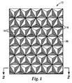
図1は、三面体の角錐型プリズムを形成するよう配置された開放空気に露出した3つの平面状小面18によってそれぞれ画定される複数のキューブコーナー素子16を有する再帰反射物品10の一部を示している。キューブコーナー光学素子16は、シーティングの一辺上に規則的な配列で適合した組として配置されており、図面のページから外側に突出するように示されている。平面状小面18は、たとえば、互いに実質的に垂直であってよい(部屋の角と同様)。小面18の間の角度は、通常は、配列内の各キューブコーナー素子で同じであり、約90°である。しかし、この角度は、米国特許第4,775,219号明細書などに記載されるように、90°からずれていてもよい。各キューブコーナー素子16の頂点20は、米国特許第3,684,348号明細書などに記載されるように、キューブコーナー素子底面の中心と垂直方向で位置合わせされる場合もあるが、米国特許第4,588,258号明細書などに記載されるようにこの頂点が傾いていてもよい。したがって、本開示の発明は、いずれかの特定のキューブコーナー形状に限定されるものではなく、現在知られている、またはこれ以降開発されるあらゆる形状を使用することもできる。
FIG. 1 shows a portion of a
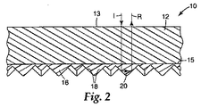
図2は、図1の線2−2に沿った、再帰反射物品10の断面図を示している。再帰反射物品10は、前面または入射面13とおよび裏面15とを有する本体部分12を有する。本体部分12は、約13×108パスカル未満の弾性率を有する。内部反射キューブコーナー光学素子16の層が、裏面15から突出し、本体部分12と光学的に関連している。小面18の裏面は、開放空気に対して露出している。キューブコーナー光学素子16は、約14×108パスカルを超える弾性率を有し、共有結合したフッ素またはケイ素を有するポリマーから少なくとも部分的に形成されている。ポリマー中にフッ素原子またはケイ素原子が存在すると、キューブコーナー光学素子16と接触しうる水滴または油滴の付着および拡散が減少することなどによって、素子16が水または油の一方または両方に対して露出する場合の再帰反射性の低下が軽減される。キューブコーナー光学素子16は、水、鉱油、または水と鉱油との両方が、素子16に適用された場合に拡散するのではなくビードを形成する(bead up)ように、望ましくは十分低い表面エネルギーを有する。望ましくは、物品10の裏面が降雨またはその他の液体に曝露した場合に、入射光Iは、本体部分12に前面13から入り、キューブコーナー光学素子16内まで通過して、キューブコーナー小面18で反射され、反射光ビームRで示される入射ビームとほぼ同じ方向に再度向かうことができる。
FIG. 2 shows a cross-sectional view of the
本体部分12は、種々の好適な可撓性で、好適には光透過性のポリマー材料から製造することができる。前述の米国特許第5,691,846号明細書において「オーバーレイフィルム」(overlay film)として記載されている材料が好ましい。たとえば、本体部分12は、望ましくは、可塑化ポリ塩化ビニルフィルム、脂肪族または芳香族のポリウレタンフィルム、アイオノマーのエチレンコポリマーフィルム、低密度ポリエチレンフィルム、ポリエチレンコポリマーフィルム(たとえば、酸官能性またはアクリル官能性のポリマーフィルム)、あるいはそれらの組み合わせから製造することができる。
The
キューブコーナー光学素子16は、種々の好適な剛性光透過性ポリマー材料から製造することができる。たとえば、キューブコーナー光学素子16全体を、フルオロポリマーから製造することができる。フルオロポリマーは、再帰反射シーティングの本体層フィルム(たとえば、米国特許第3,684,348号明細書参照)、ならびに金属化または封入されたキューブコーナー光学素子(たとえば、米国特許第6,258,443B1号明細書参照)において有用であると従来言われているが、開放空気に露出したキューブコーナー光学素子の製造には使用されていないと思われる。キューブコーナー光学素子16全体を、シロキサンポリマーから製造することもできる。「ハード」セグメントと「ソフト」ポリシロキサンセグメントとを有するポリマーは、モノリス再帰反射シーティング(たとえば、米国特許第4,668,558号明細書参照)の製造に従来使用されているが、低弾性率の透明本体部分と高弾性率のキューブコーナー光学素子とを有する再帰反射物品中の開放空気に露出したキューブコーナー光学素子の製造には使用されていないと思われる。キューブコーナー光学素子16は、種々の他の熱可塑性または熱硬化性材料(たとえば、ポリメタクリル酸メチル、ポリカーボネート、ポリウレタン、未可塑化ポリ塩化ビニル、およびエポキシアクリレート)から製造することもでき、これらの材料を、フッ素またはケイ素含有ポリマーメルト添加剤、あるいは共重合性フッ素またはケイ素含有モノマー、オリゴマーまたはポリマーに加えた後、キューブを形成することができる。当業者であれば、共有結合したフッ素またはケイ素を有するポリマーから少なくとも部分的に形成されたキューブコーナー光学素子より本開示の再帰反射物品を形成するために他の方法を使用できることは理解できるであろう。
The cube corner
単独で使用したり、熱可塑性または熱硬化性樹脂への添加剤として使用したりすることができ、それらからキューブコーナー光学素子が形成される代表的なフッ素含有またはケイ素含有材料(すなわち「キューブ樹脂」)としては、フッ素含有およびケイ素含有アクリレートおよびメタクリレート(たとえば、アクリル酸またはメタクリル酸パーフルオロアルキル、たとえば、アクリル酸メチルパーフルオロブチルスルホンアミドエチル、メタクリル酸メチルパーフルオロブチルスルホンアミドエチル、および次式のオリゴマー:
C3F7O[CF2CF(CF3)O]nCF(CF3)CONHC2H4−OCO−C(CH3)=CH2
(上式中、nは、たとえば6〜7であってよい);ポリジメチルシロキサンアクリレートおよびメタクリレート、たとえばポリエーテル改質ポリジメチルシロキサンアクリレートおよびポリエーテル改質ポリジメチルシロキサンメタクリレート);ならびにポリエーテル改質ポリジメチルシロキサンが挙げられる。
Typical fluorine-containing or silicon-containing materials (ie “cube resins”) that can be used alone or as additives to thermoplastic or thermosetting resins from which cube corner optical elements are formed )) Includes fluorine-containing and silicon-containing acrylates and methacrylates (eg, perfluoroalkyl acrylate or methacrylate, such as methyl perfluorobutylsulfonamidoethyl acrylate, methyl perfluorobutylsulfonamidoethyl methacrylate, and Oligomers:
C 3 F 7 O [CF 2 CF (CF 3) O] nCF (CF 3) CONHC 2 H 4 -OCO-C (CH 3) =
(Wherein n may be, for example, 6-7); polydimethylsiloxane acrylates and methacrylates, such as polyether modified polydimethylsiloxane acrylate and polyether modified polydimethylsiloxane methacrylate); and polyether modified Examples include polydimethylsiloxane.
図3は、本開示の方法により再帰反射物品(連続再帰反射シーティングの形態)をキャスティングし硬化させるための装置の概略図であり、この装置は全体的に30で示されている。図3に示されるように、可撓性本体層フィルム31が供給リール32から引き出される。高弾性率のフッ素またはケイ素含有キューブ樹脂34が、低弾性率本体フィルム31の上面にコーティングダイ36から適用される。本体フィルム31およびそれに適用されたキューブ樹脂層は、ゴムで覆われたニップローラー33によって、パターンが形成された工具ロール35に押し付けられる。工具ロール35中のキューブコーナー素子を形成する空隙37の上に延在するキューブ樹脂の厚さが存在する場合、その厚さは、ニップローラー33のニップ幅またはニップ圧を設定することによって調節することができる。たとえば、延在する樹脂厚さを最小限にしたり厚さが無くなったりするようにニップを設定することによって、完成した再帰反射シーティング中の個別のキューブコーナー光学素子の間のランド部分の破壊を促進することができる。この破壊によって、個別のキューブコーナー素子を隣接するキューブコーナー素子から分断することができ、完成した再帰反射シーティングをより可撓性にすることができる。
FIG. 3 is a schematic diagram of an apparatus for casting and curing a retroreflective article (in the form of a continuous retroreflective sheeting) according to the method of the present disclosure, which apparatus is generally designated 30. As shown in FIG. 3, the flexible main
成形された熱可塑性キューブ樹脂は、当業者に周知である種々の方法(たとえば、冷却されパターン形成された工具ロール)を使用して冷却して、完成キューブコーナー素子を形成することができる。熱硬化性キューブ樹脂は、当業者に周知である種々の方法(たとえば、電子ビーム曝露などの好適な放射線源;紫外線、可視光線、または赤外線などの化学線;あるいはキューブ樹脂の性質に依存したその他の好適なエネルギー源への曝露によって)を使用して1つ以上の段階で硬化させて、完成キューブコーナー素子を形成することができる。たとえば、キューブ樹脂が空隙37内に埋め込まれているときに、1つ以上の第1の放射線源39を使用して、本体層フィルム31を通して熱硬化性キューブ樹脂に照射することができる。この第1または主要の硬化ステップは、キューブコーナー光学素子を実質的に完全に硬化させることができるし、あるいは、キューブコーナー光学素子が寸法安定性となり、工具ロール35からの支持がもはや不要となる程度まで、キューブ樹脂を単に部分的に硬化させることもできる。次に、ローラー41でシーティングを工具ロール35から取り外して、キューブコーナー素子を露出させることができ、この完成した再帰反射シーティング43を巻き取りリール45で巻き取ることができる。
The molded thermoplastic cube resin can be cooled to form a finished cube corner element using various methods well known to those skilled in the art (eg, cooled and patterned tool rolls). Thermoset cube resins can be produced by various methods well known to those skilled in the art (eg, suitable radiation sources such as electron beam exposure; actinic radiation such as ultraviolet, visible, or infrared; or others depending on the nature of the cube resin. Can be cured in one or more stages to form a finished cube corner element. For example, one or more
場合により、キューブ樹脂の性質に依存して選択される1つ以上の二次的な硬化処理を使用することで、キューブコーナー光学素子のアレイをさらに硬化させ、それらの本体層フィルムへの結合を強化することができる。この2つの部分に分かれた硬化方法によって、プロセスおよび材料の最適化が可能となる。たとえば、紫外線吸収剤(より高い耐久性および耐候性を付与するため)を含有する本体層を有する再帰反射シーティングは、放射線源39を使用して透明本体層フィルムを通した可視光の1次硬化処理を行い、次に工具ロール35からシーティングを取り外し、場合により選択される第2の放射線源47を使用して、露出したキューブコーナー素子に対して紫外線の第2の硬化処理を行うことによって、製造することができる。
Optionally, one or more secondary curing processes selected depending on the nature of the cube resin can be used to further cure the array of cube corner optics and bond them to the body layer film. Can be strengthened. This two-part cure method allows process and material optimization. For example, retroreflective sheeting with a body layer containing a UV absorber (to provide greater durability and weather resistance) can be used for primary curing of visible light through a transparent body layer film using a
場合により、本体層フィルム31は、構造的および機械的耐久性を本体層フィルム31に付与する好適なキャリアフィルム(図3中には示していない)によって、キャスティングおよび硬化の間に支持することができ、このキャリアフィルムは、完成した再帰反射シーティング43を巻き取りリール45で巻き取る前に本体層フィルム31から除去される。このようなキャリアフィルムの使用は、低弾性本体層フィルムの場合に特に好ましい。
Optionally, the
本開示の方法は、再帰反射シーティングを工具ロール35から取り外した後に、加熱処理を行うこともできる。このような加熱によって、本体層フィルムまたはキューブコーナー光学素子の内部に生じうる応力が緩和し、未反応の水分および副反応生成物が除去される。通常、このような処理は、高温、たとえばキューブ樹脂のガラス転移温度より高温までシーティングを加熱することを伴う。
In the method of the present disclosure, after the retroreflective sheeting is removed from the
完成した再帰反射物品は、そのまま使用することもできるし、あるいは、キューブコーナー光学素子を開放空気に対して露出したままにする好適な支持体上に取り付けることもできる。多種多様な支持体を使用することができ、それらは当業者には周知である。代表的な支持体としては、織布、不織布、または編物(たとえば、衣類および履物に使用される)、プラスチック、皮革、金属、タイル、コンクリート、メーソンリー、および木材が挙げられる。多種多様な取付技術を使用することができ、それらは当業者には周知である。代表的な取付技術としては、縫製、接着剤、溶接(たとえば超音波溶接)、および固定具(たとえばリベット)が挙げられる。 The completed retroreflective article can be used as is or mounted on a suitable support that leaves the cube corner optical element exposed to open air. A wide variety of supports can be used and are well known to those skilled in the art. Exemplary supports include woven, non-woven, or knitted fabric (eg, used in clothing and footwear), plastic, leather, metal, tile, concrete, masonry, and wood. A wide variety of attachment techniques can be used and are well known to those skilled in the art. Typical attachment techniques include sewing, adhesives, welding (eg, ultrasonic welding), and fasteners (eg, rivets).
以下の例示的実施例において本発明をさらに説明するが、特に明記しない限り、これらの実施例におけるすべての部数およびパーセント値は、重量を基準としている。 The invention is further described in the following illustrative examples, unless stated otherwise, all parts and percentage values in these examples are on a weight basis.
実施例1
24.75部のエベクリル(EBECRYL)(商標)3700ビスフェノールAエポキシジアクリレート(UCBケミカルズ・インコーポレイテッド(UCB Chemicals,Inc.))、49.5部のトリメチロールプロパントリアクリレート、24.75部のヘキサンジオールジアクリレート、および1部のダロキュア(DAROCURE)(商標)4265光開始剤(チバ・スペシャルティ・ケミカルズ・インコーポレイテッド(Ciba Specialty Chemicals,Inc.))から、対照キューブ樹脂を形成した。3部のBYK(商標)UV3510ポリエーテル改質ポリジメチルシロキサン(ビックケミーUSAインコーポレイテッド(Byk−Chemie USA,Inc.))を、97部の上記対照キューブ樹脂に加えることによって、改質キューブ樹脂を調製した。3.5のハンド値および約108パスカル未満の弾性率を有する厚さ0.25mmの可塑化透明ポリ塩化ビニル本体層フィルム(アキレスUSA・インコーポレイテッド(Achilles USA,Inc.)のNo.KGC193)を、図3に示すような装置に取り付けた。対照キューブ樹脂および改質キューブ樹脂を、本体層フィルムに対してUV硬化させて、高さ0.9mmの開放空気に露出したキューブコーナー光学素子を有する未封止の再帰反射シーティングを形成した。対照シーティングのキューブ側を水に曝露すると、水がキューブコーナー光学素子の裏面を濡らし、再帰反射性が大きく低下した。改質キューブ樹脂シーティングを水に曝露すると、水はキューブコーナー光学素子を濡らさなかった。その代わり、適用した水は水滴となり、液体との接触面積が最小限となり、再帰反射性は大部分が保存された。鉱油、ケロシン、ミネラルスピリット、およびイソプロパノールを使用してこれらの試験を繰り返すと、これらすべてが、対照シーティングおよび改質シーティングの両方を濡らすことが分かった。
Example 1
24.75 parts EBECRYL ™ 3700 bisphenol A epoxy diacrylate (UCB Chemicals, Inc.), 49.5 parts trimethylolpropane triacrylate, 24.75 parts hexane A control cube resin was formed from diol diacrylate and 1 part DAROCURE ™ 4265 photoinitiator (Ciba Specialty Chemicals, Inc.). A modified cube resin was prepared by adding 3 parts BYK ™ UV3510 polyether modified polydimethylsiloxane (Byk-Chemie USA, Inc.) to 97 parts of the control cube resin. did. 0.25 mm thick plasticized clear polyvinyl chloride body layer film (No. KGC193 from Achilles USA, Inc.) having a hand value of 3.5 and a modulus of elasticity of less than about 10 8 Pascals Was attached to an apparatus as shown in FIG. Control cube resin and modified cube resin were UV cured to the body layer film to form an unsealed retroreflective sheeting with cube corner optical elements exposed to 0.9 mm high open air. When the cube side of the control sheeting was exposed to water, the water wetted the back of the cube corner optical element and the retroreflectivity was greatly reduced. When the modified cube resin sheeting was exposed to water, the water did not wet the cube corner optics. Instead, the applied water was water droplets, the contact area with the liquid was minimized, and the retroreflectivity was largely preserved. When these tests were repeated using mineral oil, kerosene, mineral spirits, and isopropanol, all of these were found to wet both the control sheet and the modified sheet.
実施例2
実施例1の方法を使用して、3部の共重合性材料BYK(商標)UV3500ポリエーテル改質ポリジメチルシロキサンアクリレート(ビックケミーUSAインコーポレイテッド(Byk−Chemie USA,Inc.))を97部の上記対照キューブ樹脂に加えることによって、改質キューブ樹脂を調製した。この改質キューブ樹脂を、本体層フィルムに対してUV硬化させて、高さ0.9mmの開放空気に露出したキューブコーナー光学素子を有する未封止の再帰反射シーティングを形成した。この改質キューブ樹脂シーティングを水に曝露すると、水はキューブコーナー光学素子を濡らさなかった。その代わり、適用した水は水滴となり、液体との接触面積が最小限となり、再帰反射性は大部分が保存された。鉱油、ケロシン、ミネラルスピリット、およびイソプロパノールを使用してこれらの試験を繰り返すと、これらすべてが、改質シーティングを濡らすことが分かった。
Example 2
Using the method of Example 1, 3 parts of the copolymerizable material BYK ™ UV3500 polyether modified polydimethylsiloxane acrylate (Byk-Chemie USA, Inc.) 97 parts of the above. A modified cube resin was prepared by adding to the control cube resin. This modified cube resin was UV cured on the main body layer film to form an unsealed retroreflective sheeting having cube corner optical elements exposed to 0.9 mm high open air. When this modified cube resin sheeting was exposed to water, the water did not wet the cube corner optics. Instead, the applied water was water droplets, the contact area with the liquid was minimized, and the retroreflectivity was largely preserved. When these tests were repeated using mineral oil, kerosene, mineral spirits, and isopropanol, all of these were found to wet the modified sheeting.
実施例3
実施例1の方法を使用して、10部または25部の、共重合性材料のアクリル酸メチルパーフルオロブチルスルホンアミドエチルまたはメタクリル酸メチルパーフルオロブチルスルホンアミドエチルを、90部または75部の上記対照キューブ樹脂に加えることによって、4種類の改質キューブ樹脂を調製した。これらの改質キューブ樹脂を、本体層フィルムに対してUV硬化させて、高さ0.9mmの開放空気に露出したキューブコーナー光学素子を有する未封止の再帰反射シーティングを形成した。水はこれらのキューブコーナー光学素子を濡らさなかった。その代わり、適用した水は水滴となり、液体との接触面積が最小限となり、再帰反射性は大部分が保存された。鉱油、ケロシン、ミネラルスピリット、およびイソプロパノールを使用してこれらの試験を繰り返すと、これらすべてが、改質シーティングを濡らすことが分かった。
Example 3
Using the method of Example 1, 10 parts or 25 parts of the copolymerizable material methyl perfluorobutylsulfonamidoethyl acrylate or methyl perfluorobutylsulfonamidoethyl methacrylate 90 parts or 75 parts of the above. Four modified cube resins were prepared by adding to the control cube resin. These modified cube resins were UV cured on the body layer film to form an unsealed retroreflective sheeting having cube corner optical elements exposed to 0.9 mm high open air. Water did not wet these cube corner optics. Instead, the applied water was water droplets, the contact area with the liquid was minimized, and the retroreflectivity was largely preserved. When these tests were repeated using mineral oil, kerosene, mineral spirits, and isopropanol, all of these were found to wet the modified sheeting.
対照シーティングおよび改質シーティングのそれぞれを、安全ベストに使用される軽量ポリエステル編物に縫い付けた後、水シャワー試験を行い、欧州規格(European Standard)EN−471(「業務用高視認性安全作業衣−試験方法および要求事項」(High visibility warning clothing for professional use−Test methods and requirements))の付録D(Annex D)(「湿潤時の再帰反射性能の測定方法」(Method of measuring wet retroreflective performance))に準拠して再帰反射性を測定した。次に、試料について、ISO 6330(「織物−織物試験のための家庭での洗浄および乾燥の手順」(Textiles−Domestic washing and drying procedures for textile testing))に準拠して、60℃洗浄サイクルの後、50℃乾燥サイクルを使用して、洗濯を行い、次に再帰反射性を再測定した。これらの試料について、4回のさらなる60℃洗浄サイクルの後、1回の50℃乾燥サイクル(したがって、洗浄サイクルの総数は5回になる)を行い、さらに再帰反射測定を行った。再帰反射性結果は、次式で計算される分率で表した:
性能の改善=((改質−対照)/対照)×100
キューブコーナー光学素子の弾性率値は、ナノメカニカル分析を使用して求めた。洗濯後の再帰反射性および弾性率の結果を以下の表Iに示す:
Each of the control sheet and the modified sheeting is sewn on a lightweight polyester knitted fabric used for a safety vest, and then subjected to a water shower test. -Test method and requirements "(High visibility warning for professional use)-Test methods and requirements (Appendix D (Annex D) (Method for measuring retroreflective performance in wet conditions) (Methoref) The retroreflectivity was measured according to the above. The sample is then subjected to a 6O 0 C wash cycle in accordance with ISO 6330 ("Textiles-Domestic Washing and Drying Procedures for Textile Testing"). Laundry was performed using a 50 ° C. drying cycle, and then the retroreflectivity was re-measured. These samples were subjected to four additional 60 ° C. wash cycles followed by one 50 ° C. drying cycle (thus the total number of wash cycles was 5) and further retroreflective measurements were made. The retroreflective result was expressed as a fraction calculated by the following formula:
Performance improvement = ((modified-control) / control) × 100
The elastic modulus value of the cube corner optical element was determined using nanomechanical analysis. The retroreflective and elastic results after washing are shown in Table I below:
表I

1回の洗濯後には、未改質対照試料に対して、すべての試料で性能の改善が見られた。実験3−3試料は、5回の洗浄後でも、未改質対照試料に対する性能の改善が見られた。 After one wash, all samples showed improved performance over the unmodified control sample. Experiment 3-3 The sample showed improved performance over the unmodified control sample even after 5 washes.
本明細書に引用されているすべての参考文献は、それらの記載内容全体が明示的に本開示に援用される。本開示の例示的実施形態が議論され、本開示の範囲内の実現可能な変形に対する参照が行われている。本開示の範囲から逸脱しない本開示のこれらおよびその他の変形および修正は当業者には明らかであり、本開示が、本明細書に記載の例示的実施形態に限定されるものではないことを理解されたい。したがって、本発明は、特許請求の範囲によってのみ限定されるものではない。 All references cited in this specification are expressly incorporated herein by reference in their entirety. Exemplary embodiments of the present disclosure are discussed and reference is made to possible variations within the scope of the present disclosure. These and other variations and modifications of this disclosure that do not depart from the scope of this disclosure will be apparent to those skilled in the art, and it is understood that this disclosure is not limited to the exemplary embodiments described herein. I want to be. Accordingly, the invention is not limited only by the scope of the claims.
Claims (22)
Applications Claiming Priority (2)
| Application Number | Priority Date | Filing Date | Title |
|---|---|---|---|
| US63971304P | 2004-12-28 | 2004-12-28 | |
| PCT/US2005/047070 WO2006071863A1 (en) | 2004-12-28 | 2005-12-28 | Prismatic retroreflective article with fluorine- or silicon-containing prisms |
Publications (2)
| Publication Number | Publication Date |
|---|---|
| JP2008525862A true JP2008525862A (en) | 2008-07-17 |
| JP2008525862A5 JP2008525862A5 (en) | 2009-02-12 |
Family
ID=36218611
Family Applications (1)
| Application Number | Title | Priority Date | Filing Date |
|---|---|---|---|
| JP2007549553A Pending JP2008525862A (en) | 2004-12-28 | 2005-12-28 | Prism retroreflective article having fluorine-containing or silicon-containing prism |
Country Status (10)
| Country | Link |
|---|---|
| US (1) | US7347571B2 (en) |
| EP (1) | EP1831735A1 (en) |
| JP (1) | JP2008525862A (en) |
| KR (2) | KR20130008643A (en) |
| CN (1) | CN100526917C (en) |
| AU (1) | AU2005322041B2 (en) |
| CA (1) | CA2593502C (en) |
| MX (1) | MX2007007695A (en) |
| NO (1) | NO20073967L (en) |
| WO (1) | WO2006071863A1 (en) |
Cited By (1)
| Publication number | Priority date | Publication date | Assignee | Title |
|---|---|---|---|---|
| KR20130072404A (en) * | 2011-12-22 | 2013-07-02 | 엘지이노텍 주식회사 | Retro-reflection structure for improving luminance and durability and process method |
Families Citing this family (28)
| Publication number | Priority date | Publication date | Assignee | Title |
|---|---|---|---|---|
| KR101318441B1 (en) * | 2007-07-18 | 2013-10-16 | 엘지디스플레이 주식회사 | Prism sheet, Backlight unit comprising the prism sheet and Liquid crystal display comprising the same |
| KR101292972B1 (en) * | 2007-10-25 | 2013-08-02 | 코오롱인더스트리 주식회사 | Optical sheet with elasticity |
| US7547105B2 (en) * | 2007-07-16 | 2009-06-16 | 3M Innovative Properties Company | Prismatic retroreflective article with cross-linked image layer and method of making same |
| CN101456667B (en) * | 2007-12-10 | 2011-12-21 | 鸿富锦精密工业(深圳)有限公司 | Prismatic lens producing method |
| KR101325444B1 (en) * | 2008-03-07 | 2013-11-04 | 코오롱인더스트리 주식회사 | Optical sheet |
| JP2012524381A (en) | 2009-04-15 | 2012-10-11 | スリーエム イノベイティブ プロパティズ カンパニー | Black light for light guide and display system with optical film containing voids |
| US9291752B2 (en) | 2013-08-19 | 2016-03-22 | 3M Innovative Properties Company | Retroreflecting optical construction |
| TWI605276B (en) | 2009-04-15 | 2017-11-11 | 3M新設資產公司 | Optical construction and display system incorporating same |
| KR101766494B1 (en) | 2009-04-15 | 2017-08-08 | 쓰리엠 이노베이티브 프로퍼티즈 컴파니 | Optical film for preventing optical coupling |
| BRPI1006654A2 (en) | 2009-04-15 | 2016-02-10 | 3M Innovative Properties Co | retroreflective optical constructions and optical films |
| USD665584S1 (en) | 2010-03-05 | 2012-08-21 | Orafol Europe Gmbh | Retro-reflective sheeting with a corner cube surface pattern having angular corner cube circular regions |
| US20110216412A1 (en) * | 2010-03-05 | 2011-09-08 | David Reed | Master tools with selectively orientable regions for manufacture of patterned sheeting |
| US20110242851A1 (en) * | 2010-04-06 | 2011-10-06 | Skc Haas Display Films Co., Ltd. | Double-sided light guide plate manufactured with patterned rollers |
| MX341955B (en) | 2010-04-15 | 2016-09-08 | 3M Innovative Properties Co | Retroreflective articles including optically active areas and optically inactive areas. |
| KR101954457B1 (en) | 2010-04-15 | 2019-03-05 | 쓰리엠 이노베이티브 프로퍼티즈 캄파니 | Retroreflective articles including optically active areas and optically inactive areas |
| WO2011129833A1 (en) | 2010-04-15 | 2011-10-20 | 3M Innovative Properties Company | Retroreflective articles including optically active areas and optically inactive areas |
| KR101332510B1 (en) * | 2010-09-30 | 2013-11-22 | 코오롱인더스트리 주식회사 | Condensing type optical sheet |
| CN105359009A (en) * | 2013-06-24 | 2016-02-24 | 3M创新有限公司 | Retroreflective article with multilayer seal film |
| EP3014317A4 (en) * | 2013-06-24 | 2017-01-11 | 3M Innovative Properties Company | Beaded retroreflective article with multilayer seal film |
| KR102437478B1 (en) * | 2016-06-07 | 2022-08-30 | 쓰리엠 이노베이티브 프로퍼티즈 캄파니 | Acrylic Polyvinyl Acetal Film for Light Directing Applications |
| US11297885B2 (en) | 2017-05-21 | 2022-04-12 | Nike, Inc. | Reflective articles of wear |
| US10555565B2 (en) | 2017-05-31 | 2020-02-11 | Nike, Inc. | Reflective articles of wear |
| US10444615B2 (en) | 2017-08-29 | 2019-10-15 | Avery Dennison Corporation | Retroreflective sheeting for projector-based display system |
| DE102018101291B4 (en) * | 2018-01-22 | 2020-10-29 | Hans-Erich Gubela | Use and method for producing an elastic retroreflector |
| DE102018101289B4 (en) | 2018-01-22 | 2019-10-17 | Imos Gubela Gmbh | Retroreflector with a curved surface, forming tool for the production of the retroreflector and method for the production of the molding tool |
| DE102018101292B4 (en) | 2018-01-22 | 2020-10-29 | Hans-Erich Gubela | Retroreflector element for use in traffic and injection mold |
| WO2020097095A1 (en) * | 2018-11-06 | 2020-05-14 | CLEARink Display, Inc. | High brightness retroreflector for static and switchable image displays |
| DE102019128755A1 (en) * | 2019-10-24 | 2021-04-29 | Imos Gubela Gmbh | Sensor device |
Citations (1)
| Publication number | Priority date | Publication date | Assignee | Title |
|---|---|---|---|---|
| JP2000509168A (en) * | 1996-04-30 | 2000-07-18 | ミネソタ マイニング アンド マニュファクチャリング カンパニー | Fabrication method of glitter corner cube retroreflective sheet |
Family Cites Families (102)
| Publication number | Priority date | Publication date | Assignee | Title |
|---|---|---|---|---|
| US3684348A (en) | 1970-09-29 | 1972-08-15 | Rowland Dev Corp | Retroreflective material |
| US3689346A (en) | 1970-09-29 | 1972-09-05 | Rowland Dev Corp | Method for producing retroreflective material |
| US3712706A (en) | 1971-01-04 | 1973-01-23 | American Cyanamid Co | Retroreflective surface |
| JPS5320837B1 (en) | 1971-07-07 | 1978-06-29 | ||
| US3811983A (en) | 1972-06-23 | 1974-05-21 | Rowland Dev Corp | Method for producing retroreflective sheeting |
| US3830682A (en) | 1972-11-06 | 1974-08-20 | Rowland Dev Corp | Retroreflecting signs and the like with novel day-night coloration |
| US3975083A (en) | 1974-07-24 | 1976-08-17 | Reflexite Corporation | Wide angle retroreflector assembly and method of making same |
| US4025159A (en) | 1976-02-17 | 1977-05-24 | Minnesota Mining And Manufacturing Company | Cellular retroreflective sheeting |
| US4349598A (en) | 1976-12-01 | 1982-09-14 | Minnesota Mining And Manufacturing Company | High incidence angle retroreflective material |
| US4202600A (en) | 1978-04-24 | 1980-05-13 | Avery International Corporation | Diced retroreflective sheeting |
| US4668558A (en) | 1978-07-20 | 1987-05-26 | Minnesota Mining And Manufacturing Company | Shaped plastic articles having replicated microstructure surfaces |
| US4576850A (en) | 1978-07-20 | 1986-03-18 | Minnesota Mining And Manufacturing Company | Shaped plastic articles having replicated microstructure surfaces |
| US4243618A (en) | 1978-10-23 | 1981-01-06 | Avery International Corporation | Method for forming retroreflective sheeting |
| US4332847A (en) | 1979-09-20 | 1982-06-01 | Relfexite Corporation | Method for compression molding of retroreflective sheeting and sheeting produced thereby |
| US4588258A (en) | 1983-09-12 | 1986-05-13 | Minnesota Mining And Manufacturing Company | Cube-corner retroreflective articles having wide angularity in multiple viewing planes |
| US4842893A (en) | 1983-12-19 | 1989-06-27 | Spectrum Control, Inc. | High speed process for coating substrates |
| US5097800A (en) | 1983-12-19 | 1992-03-24 | Spectrum Control, Inc. | High speed apparatus for forming capacitors |
| US4672089A (en) | 1984-08-10 | 1987-06-09 | Amerace Corporation | Retroreflective sheeting |
| US4618518A (en) | 1984-08-10 | 1986-10-21 | Amerace Corporation | Retroreflective sheeting and methods for making same |
| US4722515A (en) | 1984-11-06 | 1988-02-02 | Spectrum Control, Inc. | Atomizing device for vaporization |
| US4756931A (en) | 1984-11-30 | 1988-07-12 | Potters Industries, Inc. | Retroreflective materials and methods for their production and use |
| US4609587A (en) | 1984-11-30 | 1986-09-02 | Potters Industries, Inc. | Retroreflective materials and use |
| US4954371A (en) | 1986-06-23 | 1990-09-04 | Spectrum Control, Inc. | Flash evaporation of monomer fluids |
| US4938563A (en) | 1986-11-21 | 1990-07-03 | Minnesota Mining And Manufacturing Company | High efficiency cube corner retroflective material |
| US4775219A (en) | 1986-11-21 | 1988-10-04 | Minnesota Mining & Manufacturing Company | Cube-corner retroreflective articles having tailored divergence profiles |
| US4755425A (en) | 1987-03-09 | 1988-07-05 | Minnesota Mining And Manufacturing Company | Retroreflective sheet coated with silica layer |
| US5073404A (en) | 1987-03-09 | 1991-12-17 | Minnesota Mining And Manufacturing Company | Silica coating composition for reflective sheeting |
| US4852885A (en) | 1987-10-14 | 1989-08-01 | Shahin Baratpour | Game device |
| US4801193A (en) | 1988-03-04 | 1989-01-31 | Reflexite Corporation | Retroreflective sheet material and method of making same |
| US4895428A (en) | 1988-07-26 | 1990-01-23 | Minnesota Mining And Manufacturing Company | High efficiency retroreflective material |
| JP2990608B2 (en) | 1989-12-13 | 1999-12-13 | 株式会社ブリヂストン | Surface treatment method |
| US5264063A (en) | 1990-05-16 | 1993-11-23 | Reflexite Corporation | Method for making flexible retroreflective sheet material |
| US5229882A (en) | 1990-05-16 | 1993-07-20 | Reflexite Corporation | Colored retroreflective sheeting and method of making same |
| US5138488A (en) | 1990-09-10 | 1992-08-11 | Minnesota Mining And Manufacturing Company | Retroreflective material with improved angularity |
| US5117304A (en) * | 1990-09-21 | 1992-05-26 | Minnesota Mining And Manufacturing Company | Retroreflective article |
| US5069577A (en) | 1990-10-23 | 1991-12-03 | Murphy Patrick E | Flexible raised pavement marker |
| DE69232591T2 (en) | 1991-01-23 | 2002-08-22 | Matsushita Electric Ind Co Ltd | Water and oil repellent adsorbed film |
| US5236751A (en) | 1991-03-28 | 1993-08-17 | Reflexite Corporation | Cone collars with temporary release coating and method for making and assembling same |
| US5213872A (en) | 1991-04-19 | 1993-05-25 | Stimsonite Corporation | Preprinted retroreflective highway sign and method for making the sign |
| EP0588937B1 (en) | 1991-06-13 | 1996-08-28 | Minnesota Mining And Manufacturing Company | Retroreflecting polarizer |
| US5508084A (en) | 1991-08-28 | 1996-04-16 | Minnesota Mining And Manufacturing Company | Repositionable articles having a microstructured surface, kits for producing same, and methods of use |
| US5415911A (en) | 1992-01-16 | 1995-05-16 | Stimsonite Corporation | Photoluminescent retroreflective sheeting |
| US5200262A (en) | 1992-04-01 | 1993-04-06 | Minnesota Mining And Manufacturing Company | Launderable retroreflective applique with improved retention of retroreflective elements |
| US5260095A (en) | 1992-08-21 | 1993-11-09 | Battelle Memorial Institute | Vacuum deposition and curing of liquid monomers |
| US5831766A (en) | 1993-02-17 | 1998-11-03 | Reflexite Corporation | Retroreflective structure |
| US5637173A (en) | 1993-02-17 | 1997-06-10 | Reflexite Corporation | Method for forming a retroreflective structure having free-standing prisms |
| US5376431A (en) | 1993-05-12 | 1994-12-27 | Reflexite Corporation | Retroreflective microprism sheeting with silver/copper reflecting coating and method of making same |
| WO1995003558A1 (en) | 1993-07-19 | 1995-02-02 | Reflexite Corporation | Retroreflective structure |
| US5648145A (en) | 1993-09-10 | 1997-07-15 | Reflexite Corporation | Fire-resistant, retroreflective structure |
| EP0724738B1 (en) | 1993-10-20 | 2000-05-10 | Minnesota Mining And Manufacturing Company | Asymetric cube corner article and method of manufacture |
| US5691846A (en) | 1993-10-20 | 1997-11-25 | Minnesota Mining And Manufacturing Company | Ultra-flexible retroreflective cube corner composite sheetings and methods of manufacture |
| US5600484A (en) | 1993-10-20 | 1997-02-04 | Minnesota Mining And Manufacturing Company | Machining techniques for retroreflective cube corner article and method of manufacture |
| US5450235A (en) | 1993-10-20 | 1995-09-12 | Minnesota Mining And Manufacturing Company | Flexible cube-corner retroreflective sheeting |
| DE69428450T2 (en) | 1993-10-20 | 2002-05-16 | Minnesota Mining & Mfg | MULTIPLE STRUCTURED CUBE CORNER BODY |
| US6318867B1 (en) * | 1993-10-20 | 2001-11-20 | 3M Innovative Properties Company | Conformable cube corner retroreflective sheeting |
| US5614286A (en) | 1993-10-20 | 1997-03-25 | Minnesota Mining And Manufacturing Company | Conformable cube corner retroreflective sheeting |
| CA2188413A1 (en) | 1994-05-19 | 1995-11-30 | Tzu-Li J. Huang | Polymeric article having improved hydrophilicity and a method of making the same |
| US5512219A (en) | 1994-06-03 | 1996-04-30 | Reflexite Corporation | Method of casting a microstructure sheet having an array of prism elements using a reusable polycarbonate mold |
| US6258443B1 (en) | 1994-09-28 | 2001-07-10 | Reflexite Corporation | Textured retroreflective prism structures and molds for forming same |
| US5592330A (en) | 1995-05-19 | 1997-01-07 | Reflexite Corporation | Retroreflective prism arrays with formed air spheres therein |
| US5558740A (en) | 1995-05-19 | 1996-09-24 | Reflexite Corporation | Method and apparatus for producing seamless retroreflective sheeting |
| DE69604402T2 (en) | 1995-06-29 | 2000-03-23 | Minnesota Mining & Mfg | RETROREFLECTIVE MARKING BODY FOR WET ENVIRONMENTAL CONDITIONS |
| US5812317A (en) | 1995-10-26 | 1998-09-22 | Minnesota Mining And Manufacturing Company | Exposed lens retroreflective article having a polymeric intermediate layer disposed between microspheric and reflective layers |
| US5620775A (en) * | 1995-11-03 | 1997-04-15 | Minnesota Mining And Manufacturing Company | Low refractive index glass microsphere coated article having a smooth surface and a method for preparing same |
| US20030170426A1 (en) * | 1995-12-01 | 2003-09-11 | W. Scott Thielman | Cellular retroreflective sheeting |
| US5706132A (en) * | 1996-01-19 | 1998-01-06 | Minnesota Mining And Manufacturing Company | Dual orientation retroreflective sheeting |
| US6015214A (en) | 1996-05-30 | 2000-01-18 | Stimsonite Corporation | Retroreflective articles having microcubes, and tools and methods for forming microcubes |
| US6243112B1 (en) | 1996-07-01 | 2001-06-05 | Xerox Corporation | High density remote plasma deposited fluoropolymer films |
| US5888594A (en) | 1996-11-05 | 1999-03-30 | Minnesota Mining And Manufacturing Company | Process for depositing a carbon-rich coating on a moving substrate |
| US5948166A (en) | 1996-11-05 | 1999-09-07 | 3M Innovative Properties Company | Process and apparatus for depositing a carbon-rich coating on a moving substrate |
| US6461003B1 (en) * | 1997-06-12 | 2002-10-08 | Purdue Research Foundation | Corner cube arrays and manufacture thereof |
| US5851674A (en) | 1997-07-30 | 1998-12-22 | Minnesota Mining And Manufacturing Company | Antisoiling coatings for antireflective surfaces and methods of preparation |
| JP3580999B2 (en) | 1997-11-17 | 2004-10-27 | 日本カーバイド工業株式会社 | Triangular pyramidal cube corner retroreflective sheet |
| EP1049578B1 (en) | 1998-01-21 | 2002-12-04 | Reflexite Corporation | Extended life fluorescence polyvinyl chloride sheeting |
| US6277485B1 (en) | 1998-01-27 | 2001-08-21 | 3M Innovative Properties Company | Antisoiling coatings for antireflective surfaces and methods of preparation |
| US6589650B1 (en) | 2000-08-07 | 2003-07-08 | 3M Innovative Properties Company | Microscope cover slip materials |
| CA2329011A1 (en) | 1998-04-29 | 1999-11-04 | 3M Innovative Properties Company | Receptor sheet for inkjet printing having an embossed surface |
| US6132861A (en) | 1998-05-04 | 2000-10-17 | 3M Innovatives Properties Company | Retroreflective articles including a cured ceramer composite coating having a combination of excellent abrasion, dew and stain resistant characteristics |
| US6245833B1 (en) | 1998-05-04 | 2001-06-12 | 3M Innovative Properties | Ceramer composition incorporating fluoro/silane component and having abrasion and stain resistant characteristics |
| US6352758B1 (en) * | 1998-05-04 | 2002-03-05 | 3M Innovative Properties Company | Patterned article having alternating hydrophilic and hydrophobic surface regions |
| US6265061B1 (en) | 1998-05-04 | 2001-07-24 | 3M Innovative Properties Company | Retroflective articles including a cured ceramer composite coating having abrasion and stain resistant characteristics |
| JP2000028811A (en) * | 1998-07-13 | 2000-01-28 | Sekisui Jushi Co Ltd | Reflector having retroreflectivity and its production |
| US6228434B1 (en) | 1998-12-16 | 2001-05-08 | Battelle Memorial Institute | Method of making a conformal coating of a microtextured surface |
| US6274221B2 (en) | 1999-01-29 | 2001-08-14 | 3M Innovative Properties Company | Angular brightness microprismatic retroreflective film or sheeting incorporating a syndiotactic vinyl aromatic polymer |
| US6172810B1 (en) * | 1999-02-26 | 2001-01-09 | 3M Innovative Properties Company | Retroreflective articles having polymer multilayer reflective coatings |
| US6503564B1 (en) | 1999-02-26 | 2003-01-07 | 3M Innovative Properties Company | Method of coating microstructured substrates with polymeric layer(s), allowing preservation of surface feature profile |
| AU5452500A (en) | 1999-06-01 | 2000-12-18 | 3M Innovative Properties Company | Random microembossed receptor media |
| US6440550B1 (en) | 1999-10-18 | 2002-08-27 | Honeywell International Inc. | Deposition of fluorosilsesquioxane films |
| US6590711B1 (en) | 2000-04-03 | 2003-07-08 | 3M Innovative Properties Co. | Light directing construction having corrosion resistant feature |
| WO2001030873A1 (en) | 1999-10-27 | 2001-05-03 | 3M Innovative Properties Company | Fluorochemical sulfonamide surfactants |
| JP3975039B2 (en) | 1999-12-13 | 2007-09-12 | 日本カーバイド工業株式会社 | Triangular pyramid cube corner retroreflective element |
| US6632508B1 (en) | 2000-10-27 | 2003-10-14 | 3M Innovative Properties Company | Optical elements comprising a polyfluoropolyether surface treatment |
| US6541591B2 (en) | 2000-12-21 | 2003-04-01 | 3M Innovative Properties Company | High refractive index microreplication resin from naphthyloxyalkylmethacrylates or naphthyloxyacrylates polymers |
| US20040191481A1 (en) * | 2001-05-31 | 2004-09-30 | Volker Erb | Reflective sheet treated with fluorosilane |
| JP3820922B2 (en) * | 2001-06-14 | 2006-09-13 | ブラザー工業株式会社 | Piezoelectric actuator and inkjet head using the same |
| US20030134949A1 (en) * | 2001-07-17 | 2003-07-17 | Brown Ward Thomas | Wear-resistant coating composition and method for producing a coating |
| US6734227B2 (en) | 2001-09-24 | 2004-05-11 | 3M Innovative Properties Company | Optical elements comprising a fluoropolymer surface treatment |
| US7887889B2 (en) * | 2001-12-14 | 2011-02-15 | 3M Innovative Properties Company | Plasma fluorination treatment of porous materials |
| US6582759B1 (en) | 2002-02-15 | 2003-06-24 | 3M Innovative Properties Company | Optical elements comprising a fluorinated surface treatment comprising urethane, ester or phosphate linkages |
| US20030198814A1 (en) * | 2002-04-23 | 2003-10-23 | 3M Innovative Properties Company | Retroreflective sheeting comprising thin continuous hardcoat |
| US6905754B2 (en) * | 2002-04-26 | 2005-06-14 | 3M Innovative Properties Company | Optical elements comprising fluorochemical surface treatment |
| AU2003298540A1 (en) * | 2002-08-02 | 2004-05-25 | Avery Dennison Corporation | Process and apparatus for microreplication |
-
2005
- 2005-12-28 KR KR1020127032617A patent/KR20130008643A/en not_active Application Discontinuation
- 2005-12-28 KR KR1020077014600A patent/KR101303508B1/en active IP Right Grant
- 2005-12-28 WO PCT/US2005/047070 patent/WO2006071863A1/en active Application Filing
- 2005-12-28 CA CA2593502A patent/CA2593502C/en not_active Expired - Fee Related
- 2005-12-28 AU AU2005322041A patent/AU2005322041B2/en not_active Ceased
- 2005-12-28 MX MX2007007695A patent/MX2007007695A/en active IP Right Grant
- 2005-12-28 CN CNB2005800452351A patent/CN100526917C/en not_active Expired - Fee Related
- 2005-12-28 EP EP05857218A patent/EP1831735A1/en not_active Withdrawn
- 2005-12-28 US US11/319,965 patent/US7347571B2/en not_active Expired - Fee Related
- 2005-12-28 JP JP2007549553A patent/JP2008525862A/en active Pending
-
2007
- 2007-07-30 NO NO20073967A patent/NO20073967L/en not_active Application Discontinuation
Patent Citations (1)
| Publication number | Priority date | Publication date | Assignee | Title |
|---|---|---|---|---|
| JP2000509168A (en) * | 1996-04-30 | 2000-07-18 | ミネソタ マイニング アンド マニュファクチャリング カンパニー | Fabrication method of glitter corner cube retroreflective sheet |
Cited By (2)
| Publication number | Priority date | Publication date | Assignee | Title |
|---|---|---|---|---|
| KR20130072404A (en) * | 2011-12-22 | 2013-07-02 | 엘지이노텍 주식회사 | Retro-reflection structure for improving luminance and durability and process method |
| KR101896935B1 (en) * | 2011-12-22 | 2018-09-12 | 엘지이노텍 주식회사 | Retro-reflection structure for improving luminance and durability and process method |
Also Published As
| Publication number | Publication date |
|---|---|
| KR101303508B1 (en) | 2013-09-03 |
| CN101091123A (en) | 2007-12-19 |
| US7347571B2 (en) | 2008-03-25 |
| NO20073967L (en) | 2007-09-28 |
| WO2006071863A1 (en) | 2006-07-06 |
| EP1831735A1 (en) | 2007-09-12 |
| CA2593502A1 (en) | 2006-07-06 |
| KR20070089959A (en) | 2007-09-04 |
| MX2007007695A (en) | 2007-08-21 |
| AU2005322041A1 (en) | 2006-07-06 |
| CN100526917C (en) | 2009-08-12 |
| KR20130008643A (en) | 2013-01-22 |
| AU2005322041B2 (en) | 2009-10-08 |
| US20060158736A1 (en) | 2006-07-20 |
| CA2593502C (en) | 2013-05-21 |
Similar Documents
| Publication | Publication Date | Title |
|---|---|---|
| JP2008525862A (en) | Prism retroreflective article having fluorine-containing or silicon-containing prism | |
| AU2005322446B2 (en) | Prismatic retroreflective article and method | |
| CN1040694C (en) | Flexible cube-corner retroreflective sheeting | |
| KR101842728B1 (en) | Antireflective films comprising microstructured surface | |
| JP6637243B2 (en) | Anti-fogging anti-fouling laminate, its manufacturing method, article, its manufacturing method, and anti-fouling method | |
| KR20150125704A (en) | Multilayer structure, method for producing same, and article | |
| JPH0811211B2 (en) | Flexible louvered plastic film with protective coating and method of making same | |
| JP6684046B2 (en) | Transparent laminate | |
| JP6890011B2 (en) | Retroreflective sheet material including low modulus layer | |
| JP6689224B2 (en) | Laminated film for molding | |
| TW200815797A (en) | Retroreflective article comprising a copolyester ether composition layer and method of making same | |
| JP4778416B2 (en) | Photocurable adhesive composition and its use in optical field | |
| CN101361011A (en) | Optical films comprising high refractive index and antireflective coatings | |
| TW293091B (en) | Plastic lens and preparation thereof | |
| Park et al. | Sustainable antireflection using recoverable nanopattern arrays | |
| JP2007305673A (en) | Photoelectric sensor | |
| JP2019091071A (en) | Laminated film for molding | |
| JP2003300282A (en) | Hydrophilic film laminate | |
| JP2002098809A (en) | Light diffusing sheet | |
| KR20230130347A (en) | Release film, manufacturing method for same and manufacturing method for artificial leather using same | |
| CN117120257A (en) | Transfer film, hard coat molded body, and method for producing same | |
| JPH04214744A (en) | Production of uneven pattern |
Legal Events
| Date | Code | Title | Description |
|---|---|---|---|
| A521 | Written amendment |
Free format text: JAPANESE INTERMEDIATE CODE: A523 Effective date: 20081217 |
|
| A621 | Written request for application examination |
Free format text: JAPANESE INTERMEDIATE CODE: A621 Effective date: 20081217 |
|
| A131 | Notification of reasons for refusal |
Free format text: JAPANESE INTERMEDIATE CODE: A131 Effective date: 20110308 |
|
| A601 | Written request for extension of time |
Free format text: JAPANESE INTERMEDIATE CODE: A601 Effective date: 20110608 |
|
| A602 | Written permission of extension of time |
Free format text: JAPANESE INTERMEDIATE CODE: A602 Effective date: 20110615 |
|
| A601 | Written request for extension of time |
Free format text: JAPANESE INTERMEDIATE CODE: A601 Effective date: 20110630 |
|
| A602 | Written permission of extension of time |
Free format text: JAPANESE INTERMEDIATE CODE: A602 Effective date: 20110707 |
|
| A601 | Written request for extension of time |
Free format text: JAPANESE INTERMEDIATE CODE: A601 Effective date: 20110801 |
|
| A602 | Written permission of extension of time |
Free format text: JAPANESE INTERMEDIATE CODE: A602 Effective date: 20110808 |
|
| A02 | Decision of refusal |
Free format text: JAPANESE INTERMEDIATE CODE: A02 Effective date: 20111108 |