JP2008525779A - Method for recovering noble gases from gas mixtures - Google Patents
Method for recovering noble gases from gas mixtures Download PDFInfo
- Publication number
- JP2008525779A JP2008525779A JP2007547615A JP2007547615A JP2008525779A JP 2008525779 A JP2008525779 A JP 2008525779A JP 2007547615 A JP2007547615 A JP 2007547615A JP 2007547615 A JP2007547615 A JP 2007547615A JP 2008525779 A JP2008525779 A JP 2008525779A
- Authority
- JP
- Japan
- Prior art keywords
- gas
- column
- rich
- stream
- noble
- Prior art date
- Legal status (The legal status is an assumption and is not a legal conclusion. Google has not performed a legal analysis and makes no representation as to the accuracy of the status listed.)
- Pending
Links
Images


Classifications
-
- C—CHEMISTRY; METALLURGY
- C01—INORGANIC CHEMISTRY
- C01B—NON-METALLIC ELEMENTS; COMPOUNDS THEREOF; METALLOIDS OR COMPOUNDS THEREOF NOT COVERED BY SUBCLASS C01C
- C01B23/00—Noble gases; Compounds thereof
-
- C—CHEMISTRY; METALLURGY
- C01—INORGANIC CHEMISTRY
- C01B—NON-METALLIC ELEMENTS; COMPOUNDS THEREOF; METALLOIDS OR COMPOUNDS THEREOF NOT COVERED BY SUBCLASS C01C
- C01B23/00—Noble gases; Compounds thereof
- C01B23/001—Purification or separation processes of noble gases
- C01B23/0036—Physical processing only
- C01B23/0042—Physical processing only by making use of membranes
-
- B—PERFORMING OPERATIONS; TRANSPORTING
- B01—PHYSICAL OR CHEMICAL PROCESSES OR APPARATUS IN GENERAL
- B01D—SEPARATION
- B01D15/00—Separating processes involving the treatment of liquids with solid sorbents; Apparatus therefor
- B01D15/08—Selective adsorption, e.g. chromatography
- B01D15/10—Selective adsorption, e.g. chromatography characterised by constructional or operational features
- B01D15/24—Selective adsorption, e.g. chromatography characterised by constructional or operational features relating to the treatment of the fractions to be distributed
-
- B—PERFORMING OPERATIONS; TRANSPORTING
- B01—PHYSICAL OR CHEMICAL PROCESSES OR APPARATUS IN GENERAL
- B01D—SEPARATION
- B01D53/00—Separation of gases or vapours; Recovering vapours of volatile solvents from gases; Chemical or biological purification of waste gases, e.g. engine exhaust gases, smoke, fumes, flue gases, aerosols
- B01D53/02—Separation of gases or vapours; Recovering vapours of volatile solvents from gases; Chemical or biological purification of waste gases, e.g. engine exhaust gases, smoke, fumes, flue gases, aerosols by adsorption, e.g. preparative gas chromatography
- B01D53/025—Separation of gases or vapours; Recovering vapours of volatile solvents from gases; Chemical or biological purification of waste gases, e.g. engine exhaust gases, smoke, fumes, flue gases, aerosols by adsorption, e.g. preparative gas chromatography with wetted adsorbents; Chromatography
-
- C—CHEMISTRY; METALLURGY
- C01—INORGANIC CHEMISTRY
- C01B—NON-METALLIC ELEMENTS; COMPOUNDS THEREOF; METALLOIDS OR COMPOUNDS THEREOF NOT COVERED BY SUBCLASS C01C
- C01B23/00—Noble gases; Compounds thereof
- C01B23/001—Purification or separation processes of noble gases
- C01B23/0036—Physical processing only
- C01B23/0052—Physical processing only by adsorption in solids
-
- G—PHYSICS
- G01—MEASURING; TESTING
- G01N—INVESTIGATING OR ANALYSING MATERIALS BY DETERMINING THEIR CHEMICAL OR PHYSICAL PROPERTIES
- G01N30/00—Investigating or analysing materials by separation into components using adsorption, absorption or similar phenomena or using ion-exchange, e.g. chromatography or field flow fractionation
- G01N30/02—Column chromatography
-
- B—PERFORMING OPERATIONS; TRANSPORTING
- B01—PHYSICAL OR CHEMICAL PROCESSES OR APPARATUS IN GENERAL
- B01D—SEPARATION
- B01D2258/00—Sources of waste gases
- B01D2258/02—Other waste gases
- B01D2258/0216—Other waste gases from CVD treatment or semi-conductor manufacturing
-
- C—CHEMISTRY; METALLURGY
- C01—INORGANIC CHEMISTRY
- C01B—NON-METALLIC ELEMENTS; COMPOUNDS THEREOF; METALLOIDS OR COMPOUNDS THEREOF NOT COVERED BY SUBCLASS C01C
- C01B2210/00—Purification or separation of specific gases
- C01B2210/0029—Obtaining noble gases
-
- C—CHEMISTRY; METALLURGY
- C01—INORGANIC CHEMISTRY
- C01B—NON-METALLIC ELEMENTS; COMPOUNDS THEREOF; METALLOIDS OR COMPOUNDS THEREOF NOT COVERED BY SUBCLASS C01C
- C01B2210/00—Purification or separation of specific gases
- C01B2210/0029—Obtaining noble gases
- C01B2210/0037—Xenon
-
- Y—GENERAL TAGGING OF NEW TECHNOLOGICAL DEVELOPMENTS; GENERAL TAGGING OF CROSS-SECTIONAL TECHNOLOGIES SPANNING OVER SEVERAL SECTIONS OF THE IPC; TECHNICAL SUBJECTS COVERED BY FORMER USPC CROSS-REFERENCE ART COLLECTIONS [XRACs] AND DIGESTS
- Y02—TECHNOLOGIES OR APPLICATIONS FOR MITIGATION OR ADAPTATION AGAINST CLIMATE CHANGE
- Y02C—CAPTURE, STORAGE, SEQUESTRATION OR DISPOSAL OF GREENHOUSE GASES [GHG]
- Y02C20/00—Capture or disposal of greenhouse gases
- Y02C20/30—Capture or disposal of greenhouse gases of perfluorocarbons [PFC], hydrofluorocarbons [HFC] or sulfur hexafluoride [SF6]
Abstract
【課題】ガス流から希ガスを回収する方法及びそのための機器を提供する。
【解決手段】1つが希ガスであり、他が典型的にヘリウム及び/又は窒素、アルゴン、及び比較的軽質のフッ化炭素である複数の成分を含む第1のガス混合物からキセノン又はクリプトンのような希ガスを回収する方法。ガス混合物は、ガス混合物の他の成分から希ガスを分離するためにガスクロマトグラフィーカラムまで最初に運ばれる。希ガスは、カラムを通って比較的ゆっくり進むので、他の成分は、比較的遅い希ガスの前にカラムから排出される。これらの他の成分の排出に続いて、搬送ガスがカラムに供給されてそこから希ガスを追い出す。希ガス及び搬送ガスを含む排出ガスは、再利用のためにカラムに再循環して戻すことができる希ガスリッチなガス流及びパージガスリッチなガス流に第2のガス混合物を分離する膜分離器までカラムから運ばれる。希ガスリッチなガス流は、次に、その再利用の前に浄化される。
【選択図】図6A method for recovering a rare gas from a gas stream and an apparatus therefor are provided.
Like a xenon or krypton from a first gas mixture comprising a plurality of components, one is a noble gas and the other is typically helium and / or nitrogen, argon, and a relatively light fluorocarbon. To recover rare gases. The gas mixture is first conveyed to a gas chromatography column to separate the noble gas from the other components of the gas mixture. As the noble gas travels relatively slowly through the column, other components are exhausted from the column before the relatively slow noble gas. Following the discharge of these other components, a carrier gas is supplied to the column to drive out the noble gas therefrom. The exhaust gas, including the noble gas and carrier gas, can be recirculated back to the column for reuse up to a membrane separator that separates the second gas mixture into a noble gas rich gas stream and a purge gas rich gas stream. Carried from the column. The noble gas rich gas stream is then purified prior to its reuse.
[Selection] Figure 6
Description
本発明は、ガス流から希ガスを回収する方法及びそのための機器に関する。本発明は、半導体処理チャンバから排出された排ガス流からの希ガスの回収、及び患者によって吐き出されたガスからの希ガスの回収においても用途を見出すことができる。 The present invention relates to a method for recovering a noble gas from a gas stream and an apparatus therefor. The present invention can also find use in the recovery of noble gases from an exhaust gas stream exhausted from a semiconductor processing chamber and in the recovery of noble gases from gas exhaled by a patient.
集積回路製作の共通の要件は、半導体基板上に形成された誘電体における接点、バイア、及びトレンチのような開口部のプラズマエッチングである。装置の幾何学形状が益々小さくなると、高アスペクト比を有する深くて狭い開口部を形成する要件が存在する。酸化珪素でこのような開口部を形成するための1つの好ましい技術は、プラズマエッチング技術であり、そこでは、x≧1、y≧1、及びz≧0の場合の一般式CxFyHzを有するフッ化炭素エッチャントガスが、エッチャントガスのための不活性搬送ガスを提供し、酸化珪素の攻撃においてフルオレンを助ける二重の役割を果たす1つ又はそれよりも多くの希ガスと共にプラズマエッチング反応器の処理チャンバに供給される。 A common requirement in integrated circuit fabrication is plasma etching of openings such as contacts, vias, and trenches in dielectrics formed on a semiconductor substrate. As device geometries get smaller and smaller, there is a requirement to form deep and narrow openings with high aspect ratios. One preferred technique for forming such openings in silicon oxide is a plasma etching technique, where the general formula C x F y H for x ≧ 1, y ≧ 1, and z ≧ 0. Fluorocarbon etchant gas with z provides an inert carrier gas for the etchant gas and plasma etch with one or more noble gases that play a dual role in assisting fluorene in silicon oxide attack Supplied to the processing chamber of the reactor.
希ガスの1つとしてのキセノンの用途は、アルゴンだけを用いるシステムに比較して選択性の増大及び耐損傷性の低減をもたらすことが見出されている。しかし、キセノンは、大気中に非常に低濃度で発生するので、その費用は非常に高く(キセノンの時価は、約4$/slである)、その利用可能性は幾分限定される可能性がある。4つの処理チャンバを含むプラズマエッチング反応器内のキセノンの推定使用量は、1年当たり約250,000から500,000リットルであることを考えると、処理器具から排出された流出流内に含まれるキセノン及び/又はクリプトンのような高価な希ガスを回収し、再利用することは非常に望ましい。 The use of xenon as one of the rare gases has been found to provide increased selectivity and reduced damage resistance compared to systems using only argon. However, since xenon occurs at very low concentrations in the atmosphere, its cost is very high (the market price of xenon is about 4 $ / sl) and its availability may be somewhat limited. There is. Given that the estimated xenon usage in a plasma etch reactor containing four processing chambers is about 250,000 to 500,000 liters per year, it is included in the effluent discharged from the processing equipment. It is highly desirable to recover and reuse expensive noble gases such as xenon and / or krypton.
しかし、このような希ガス又は希ガス混合物の回収は、流出流の他の成分によって妨げられる。これらは、以下のものを含むことができる。
・未消費反応物質、
・プラズマエッチングからの副産物、
・チャンバから流出流を引き出すためのポンプシステムに供給されたパージガス、及び
・他の希ガス。
However, recovery of such noble gases or noble gas mixtures is hindered by other components of the effluent stream. These can include the following:
・ Unconsumed reactants,
By-products from plasma etching,
Purge gas supplied to the pump system to draw the effluent from the chamber, and other noble gases.
未消費フッ化炭素エッチャントは、このようなガスが、比較的高い温室効果活性を有することが公知なので特に望ましくない。
キセノンはまた、例えば、臨床麻酔として及び神経保護としていくつかの医療用途を有する。このような用途では、典型的に主成分として酸素及びキセノンを含むガスの混合物が患者に送出される。キセノンの費用に起因して、患者によって吐き出されるガス内に含まれるキセノンを回収し、再利用することが望ましい。
Unconsumed fluorocarbon etchants are particularly undesirable because such gases are known to have relatively high greenhouse activity.
Xenon also has several medical uses, for example as clinical anesthesia and as neuroprotection. In such applications, a mixture of gases typically containing oxygen and xenon as the main components is delivered to the patient. Due to the cost of xenon, it is desirable to recover and reuse xenon contained in the gas exhaled by the patient.
第1の態様では、本発明は、1つが希ガスである複数の成分を含むガス混合物から希ガスを回収する方法を提供し、本方法は、ガスクロマトグラフィーカラムにガス混合物を供給してガス混合物の成分を分離し、かつそこから連続的に成分を排出する段階と、搬送ガスをカラムに供給する段階と、カラムから排出された搬送ガスと希ガスとを含む排出ガスを、希ガスリッチなガス流と搬送ガスリッチなガス流に分離する段階と、希ガスリッチなガス流を浄化する段階とを含む。 In a first aspect, the present invention provides a method for recovering a noble gas from a gas mixture comprising a plurality of components, one of which is a noble gas, the method comprising supplying the gas mixture to a gas chromatography column to provide a gas Separating the components of the mixture and continuously discharging the components therefrom, supplying the carrier gas to the column, and the exhaust gas containing the carrier gas and the rare gas discharged from the column are rich in noble gas. Separating the gas stream into a carrier gas rich gas stream and purifying the noble gas rich gas stream.
搬送ガスリッチなガス流は、好ましくはガスクロマトグラフィーカラムに戻される。その結果、搬送ガスリッチなガス流内に存在するあらゆる希ガスは、失われずにガスクロマトグラフィーカラムに戻される。
排出ガスは、排出ガスを希ガスリッチなガス流と搬送ガスリッチなガス流に分離するための膜分離器まで運ぶことができる。代替的に、排出ガスは、排出ガス内に含まれる希ガスを選択的に吸着するための吸着材料を収容する貯蔵容器まで運ぶことができる。希ガスは、好ましくは、排気及び/又は熱再生によって吸着材料から脱着される。次に、希ガスリッチなガス流は、搬送ガスから希ガスリッチなガス流を浄化するために貯蔵容器から膜分離器まで運ぶことができる。膜分離器は、希ガスリッチなガス流を第2の希ガスリッチなガス流と希ガス希薄ガス流に分離することができ、これは、ガスクロマトグラフィーカラムに戻ることができ、それによってここでもまた、希ガス希薄ガス流内に存在するあらゆる希ガスは、失われずにガスクロマトグラフィーカラムに戻される。
The carrier gas rich gas stream is preferably returned to the gas chromatography column. As a result, any noble gas present in the carrier gas rich gas stream is returned to the gas chromatography column without being lost.
The exhaust gas can be carried to a membrane separator for separating the exhaust gas into a rare gas rich gas stream and a carrier gas rich gas stream. Alternatively, the exhaust gas can be carried to a storage container that contains an adsorbent material for selectively adsorbing noble gases contained in the exhaust gas. The noble gas is preferably desorbed from the adsorbent material by exhaust and / or heat regeneration. The noble gas rich gas stream can then be conveyed from the storage vessel to the membrane separator to purify the noble gas rich gas stream from the carrier gas. The membrane separator can separate the noble gas rich gas stream into a second noble gas rich gas stream and a noble gas lean gas stream, which can be returned to the gas chromatography column, thereby again here. Any noble gas present in the noble gas lean gas stream is returned to the gas chromatography column without being lost.
希ガスリッチなガス流は、希ガスリッチなガス流から水、炭化水素、搬送ガス、及びそこからの軽質フッ化炭素のうちの1つ又はそれよりも多くの除去によって浄化することができる。希ガスリッチなガス流の浄化は、好ましくは、希ガスリッチなガス流内の希ガスの濃度が所定レベル又はそれを超えるまで繰り返される。二酸化炭素は、例えば、ガスクロマトグラフィーカラムとガス分離装置の間に設けられた1つ又はそれよりも多くのトラップにおいて、排出ガスからそれを希ガスリッチなガス流と搬送ガスリッチなガス流に分離する前に除去することができる。 A noble gas rich gas stream can be purified from the noble gas rich gas stream by removal of one or more of water, hydrocarbons, carrier gas, and light fluorocarbons therefrom. Purification of the noble gas rich gas stream is preferably repeated until the concentration of the noble gas in the noble gas rich gas stream is at or above a predetermined level. Carbon dioxide, for example, separates it from the exhaust gas into a noble gas rich gas stream and a carrier gas rich gas stream in one or more traps provided between the gas chromatography column and the gas separator. Can be removed before.
ガス混合物は、好ましくは、それをガスクロマトグラフィーカラムに供給する前にその1つ又は複数の成分を除去するために処理される。ガス混合物は、ガス混合物の1つ又はそれよりも多くの成分を他の種に変換するために除去装置内で処理することができる。除去装置は、ガス混合物の成分の少なくとも1つと反応するための反応物質を含むことができる。代替的に又は追加的に、ガス混合物は、ガス混合物から1つ又はそれよりも多くの成分を分離するための分離器を通して運ぶことができる。これは、そうでなければ希ガスの少なくとも一部と同じ速度で及び従ってそれと共にガスクロマトグラフィーカラムを通って進むであろうガス混合物の成分を、ガス混合物がカラムに入る前にガス混合物から除去することを可能にする。それによって、カラムから排出される排出ガスのその後の浄化を促進することができる。 The gas mixture is preferably treated to remove its component or components before feeding it to the gas chromatography column. The gas mixture can be processed in a removal device to convert one or more components of the gas mixture to other species. The removal device can include a reactant for reacting with at least one of the components of the gas mixture. Alternatively or additionally, the gas mixture can be conveyed through a separator for separating one or more components from the gas mixture. This removes the components of the gas mixture that would otherwise travel through the gas chromatography column at the same rate as and at least part of the noble gas from the gas mixture before it enters the column. Make it possible to do. Thereby, the subsequent purification of the exhaust gas discharged from the column can be facilitated.
従って、第2の態様では、本発明は、1つが希ガスである複数の成分を含むガス混合物から希ガスを回収する方法を提供し、本方法は、ガスクロマトグラフィーカラムにガス混合物を供給してガス混合物の成分を分離し、かつそこから連続的に成分を排出する段階と、搬送ガスをカラムに供給する段階と、カラムから排出された搬送ガスと希ガスとを含む排出ガスを希ガスリッチなガス流と搬送ガスリッチなガス流に分離する段階とを含み、ガス混合物は、そうでなければ希ガスの少なくとも一部と共にカラムを通って進むであろう1つ又はそれよりも多くの成分をガス混合物から除去するために、カラムへのガス混合物の供給の前に処理される。 Accordingly, in a second aspect, the present invention provides a method for recovering a noble gas from a gas mixture comprising a plurality of components, one of which is a noble gas, the method supplying the gas mixture to a gas chromatography column. Separating the components of the gas mixture and continuously discharging the components therefrom, supplying the carrier gas to the column, and the exhaust gas containing the carrier gas and the rare gas exhausted from the column is rich in a rare gas. Separating the gas stream into a carrier gas rich gas stream, wherein the gas mixture removes one or more components that would otherwise travel through the column with at least a portion of the noble gas. In order to be removed from the gas mixture, it is processed before feeding the gas mixture to the column.
ガス混合物は、好ましくは、ガス混合物を含む廃ガスを受け取るための少なくとも1つの廃ガス貯蔵容器からガスクロマトグラフィーカラムに供給される。廃ガスは、上述の少なくとも1つの貯蔵容器内に貯蔵する前に圧縮することができる。代替的に又は追加的に、希ガスは、各貯蔵容器内に設けられた吸着材上に選択的に吸着させることができる。希ガスは、排気、パージ、及び/又は熱再生によって吸着材から脱着させることができる。上述の少なくとも1つの貯蔵容器内で吸着材料を再生するためのパージガスは、ガスクロマトグラフィーカラムに搬送ガスを供給するための搬送ガスの供給源から供給することができる。
希ガスは、キセノン、クリプトン、ネオン、及びこれらの混合物のうちの1つを含むことができる。搬送ガスは、ヘリウム及び水素の一方を含むことができる。
The gas mixture is preferably supplied to the gas chromatography column from at least one waste gas storage vessel for receiving waste gas containing the gas mixture. The waste gas can be compressed before being stored in at least one storage container as described above. Alternatively or additionally, the noble gas can be selectively adsorbed on an adsorbent provided in each storage vessel. The noble gas can be desorbed from the adsorbent by evacuation, purging, and / or heat regeneration. The purge gas for regenerating the adsorbent material in the at least one storage vessel described above can be supplied from a carrier gas source for supplying carrier gas to the gas chromatography column.
The noble gas can include one of xenon, krypton, neon, and mixtures thereof. The carrier gas can include one of helium and hydrogen.
第3の態様では、本発明は、1つが希ガスである複数の成分を含むガス混合物から希ガスを回収するための機器を提供し、この機器は、ガス混合物の成分を分離し、かつ連続的にガス混合物から成分を排出するためのガスクロマトグラフィーカラムと、搬送ガスをカラムに供給するための手段と、カラムから排出された搬送ガスと希ガスとを含む排出ガスを希ガスリッチなガス流と搬送ガスリッチなガス流に分離するための手段と、希ガスリッチなガス流を浄化するための手段とを含む。 In a third aspect, the present invention provides an apparatus for recovering a noble gas from a gas mixture comprising a plurality of components, one of which is a noble gas, the apparatus separating and continuously separating the components of the gas mixture. Gas chromatography column for exhausting the components from the gas mixture, means for supplying the carrier gas to the column, and the exhaust gas comprising the carrier gas and the rare gas exhausted from the column in a rare gas rich gas stream. And means for separating the carrier gas rich gas stream and means for purifying the rare gas rich gas stream.
第4の態様では、本発明は、1つが希ガスである複数の成分を含むガス混合物から希ガスを回収するための機器を提供し、この機器は、ガス混合物の成分を分離し、かつ連続的にガス混合物から成分を排出するためのガスクロマトグラフィーカラムと、搬送ガスをカラムに供給するための手段と、カラムから排出された搬送ガスと希ガスとを含む排出ガスを希ガスリッチなガス流と搬送ガスリッチなガス流に分離するための手段と、そうでなければ希ガスの少なくとも一部と共にカラムを通って進むであろう1つ又はそれよりも多くの成分をガス混合物から除去するためにガス混合物をカラムへのその供給の前に処理するための手段とを含む。
本発明の第1の態様に関して上述した特徴は、第2の態様から第4の態様まで等しく適用可能であり、逆もまた同様である。
本発明の好ましい特徴を添付の図面を参照してここで以下に説明する。
In a fourth aspect, the present invention provides an apparatus for recovering a noble gas from a gas mixture comprising a plurality of components, one of which is a noble gas, the apparatus separating and continuously separating the components of the gas mixture. Gas chromatography column for exhausting the components from the gas mixture, means for supplying the carrier gas to the column, and the exhaust gas comprising the carrier gas and the rare gas exhausted from the column in a rare gas rich gas stream. And means for separating the carrier gas rich gas stream, and to remove one or more components from the gas mixture that would otherwise travel through the column with at least a portion of the noble gas. Means for treating the gas mixture prior to its supply to the column.
Features described above with respect to the first aspect of the invention are equally applicable from the second aspect to the fourth aspect, and vice versa.
Preferred features of the present invention will now be described hereinbelow with reference to the accompanying drawings.
図面に例示するガス回収システムは、プラズマエッチング反応器の処理チャンバから排出された流出流内に含まれる希ガスの回収で用いるために提供される。しかし、本発明は、このような目的に限定されない。例えば、本発明の態様はまた、患者によって吐き出されるガスからキセノンを分離することにより、手術用の麻酔剤として用いる時、及びプラズマチャンバからキセノンを送り込むのに用いるポンプシステムに供給されるパージガスから及びチャンバから送り込むガス流内の他の汚染物質からキセノンを分離することにより、極端紫外線(EUV)照射の発生のための供給源として用いる時にキセノンの回収の用途を見出すものである。 The gas recovery system illustrated in the drawings is provided for use in recovering noble gases contained in an effluent stream exiting a processing chamber of a plasma etching reactor. However, the present invention is not limited to such an object. For example, aspects of the invention can also separate xenon from a gas exhaled by a patient, and as a surgical anesthetic, and from a purge gas supplied to a pump system used to pump xenon from a plasma chamber and Separation of xenon from other contaminants in the gas stream coming from the chamber finds use for xenon recovery when used as a source for the generation of extreme ultraviolet (EUV) radiation.
以下に示す実施例は、流出流からのキセノンの回収に関するが、本発明は、キセノンの回収に制限されない。本発明はまた、クリプトン並びにキセノン及びクリプトンの混合物のような他のガスの回収に適切である。回収ガスは、「そのままで」再利用することができ、又は回収ガスを再利用前に別のガスと混合することができる。例えば、回収希ガスは、再利用前にフレッシュアルゴンと混合することができる。本明細書で用いる用語「希ガス」は、単一ガスに限定されることなく、2つ又はそれよりも多くの希ガスの混合物も含む。 The following examples relate to xenon recovery from the effluent stream, but the invention is not limited to xenon recovery. The present invention is also suitable for the recovery of other gases such as krypton and mixtures of xenon and krypton. The recovered gas can be reused “as is”, or the recovered gas can be mixed with another gas prior to reuse. For example, the recovered noble gas can be mixed with fresh argon before reuse. The term “noble gas” as used herein is not limited to a single gas, but also includes a mixture of two or more noble gases.
図1を参照すると、プラズマエッチング反応器の処理チャンバ10は、図1に14で全体的に指し示すガス供給装置から処理ガスを受け取るための少なくとも1つの吸気口12を備える。必要な量のガスが処理チャンバ10に供給されることを保証するシステムコントローラによって制御されている質量流量コントローラは、各それぞれのガスに対して設けることができる。この実施例では、処理ガスは、ヘリウム及びアルゴンと共に処理チャンバ10内に導かれている処理用の反応物質としてエッチャント及び酸素を含む。好ましいエッチャントの例は、CF4、C2F6、C3F8、及びC4F8のようなx≧1及びy≧1の場合の一般式CxFyを有するペルフルオロ化合物を含むが、CHF3、C2HF5、及びCH2F2のようなハイドロフルオロカーボンガス、フッ素、NF3、SF6、又はCl2又はHBrのようなあらゆる他の好ましいハロゲン含有成分を含む他のエッチャントもまた用いることができる。ヘリウムは、一般的に、ウェーハの背面を冷却するために比較的少量で処理チャンバ10に供給される。アルゴンは、処理チャンバ10内に導かれている処理のための誘導ガスを提供する。
Referring to FIG. 1, the plasma etching
プラズマエッチング反応器は、そこに設けられた基板の表面を望ましい幾何学形状にエッチングするためのプラズマを生成するためのあらゆる好ましい反応器とすることができる。例としては、誘導結合されたプラズマエッチング反応器、電子サイクロトロン共鳴(ECR)プラズマエッチング反応器、又は他の高密度プラズマ反応器を含む。この例では、プラズマエッチング反応器は、半導体製造工程が行われる反応器であり、そこでは基板の表面は、ポリシリコン又は誘電体膜を含むことができる。代替的に、フラットパネルディスプレイの製造は、プラズマエッチング反応器内で行うことができる。 The plasma etching reactor can be any preferred reactor for generating a plasma for etching the surface of the substrate provided therein into a desired geometry. Examples include inductively coupled plasma etch reactors, electron cyclotron resonance (ECR) plasma etch reactors, or other high density plasma reactors. In this example, the plasma etch reactor is a reactor in which a semiconductor manufacturing process is performed, where the surface of the substrate can include polysilicon or a dielectric film. Alternatively, the manufacture of flat panel displays can be done in a plasma etch reactor.
処理チャンバ10は、クリプトン、キセノン、又はクリプトン又はキセノンの混合物のような希ガスを受け取るための第2の吸気口16を備える。図示の例では、希ガスはキセノンである。キセノンは、一般的に、キセノンがシステムコントローラの制御下で質量流量コントローラ22を通って第2の吸気口16に供給される緩衝タンク20にキセノンを提供する1つ又はそれよりも多くのガスシリンダを含むキセノン供給装置18から提供される。図1に示すように、質量流量コントローラ22は、再循環システムコントローラ23に対してその現在の設定値を示す信号を出す。
The
排ガス流は、図1に26で指し示すポンプシステムによって処理チャンバ10の排出口24から引き出される。エッチング処理中に、反応物質の部分のみが消費されることになり、そこで処理チャンバ10の排出口24から排出された排ガス流は、反応物質、チャンバに供給した非反応性の希ガス、及びエッチング処理からの副産物の混合物を含むことになる。例えば、流出流は、CXFY、O2、Xe、Ar、He、SiF4、並びにCO及びCO2の一方又は両方の混合物を含むことができる。
The exhaust gas stream is withdrawn from the outlet 24 of the
ポンプシステム26は、処理チャンバ10から流出流を引き出すためのターボ分子ポンプ28を含む。キセノン分子は、軽質ガスと比較して「重質」であり、従って、ターボ分子ポンプ28を通ってよりゆっくり移動する。仕事が重質キセノン分子に対して為された状態で、これらの内部エネルギが増加して熱が生じる。ターボ分子ポンプ28の金属インペラが高熱伝導率を有するので、この熱は、インペラを通って急速に導かれるが、ターボ分子ポンプ28の固定子構成要素は、冷たいままである。キセノンを送り込んでいる間中ポンプが損傷しないように、この例のようにヘリウム又は窒素のようなキセノンよりも軽質のパージガスは、ターボ分子ポンプ28のパージポート34とパージガスの供給源32を接続する導管システム30を通じてターボ分子ポンプ28に供給される。平均してN2及びHeのような軽質ガス分子は、Xeよりも速く進み、そこでこれらのガスは、インペラに対してより高い衝突速度を有する。これらのガスはまた、Xeよりも高い熱伝導率を有するので、パージガスの分子は、ポンプインペラから熱を引き出す。それによって、このようなパージガスの非存在下で可能なものよりも遥かに長い期間信頼することができるポンプ作動を可能にするレベルでターボ分子ポンプ28の内側の温度を維持することができる。
The
ターボ分子ポンプ28は、処理チャンバ10内に少なくとも10-3mbarの真空状態を生成することができる。流出流は、一般的に、約1mbarの圧力でターボ分子ポンプ28から排出される。これに鑑みて、ポンプシステム26はまた、ターボ分子ポンプ28から排出された流出流を受け取り、この実施例では周囲を僅かに超える圧力まで流出流の圧力を上昇させるための補助ポンプ36を含む。補助ポンプ36はまた、補助ポンプ36のポンプ機構に対する損傷を防止するパージポート38を通じて導管30からパージガスを受け取る。
The
従って、補助ポンプ36から排出された流出流は、ここで処理チャンバ10から排出されたガスに加えてN2を含む。流出流から成分の一部を除去するために、流出流は、連続的に除去装置40を通って運ばれる。除去装置40は、流出流から望ましい成分を除去するための焼却、プラズマ除去、又は熱分解ユニットのようなあらゆる望ましい形態を取ることができる。補助ポンプ36から下流に除去装置40を設置する代わりとして、除去装置40の性質に応じてターボ分子ポンプ28と補助ポンプ36の間に除去装置40を設置することがより望ましい場合があり、補助ポンプ36から排出された流出流の圧力の上昇ではなく、大気圧以下の圧力で除去装置40を作動することがより効率的な場合がある。
Thus, the effluent stream discharged from the
CXFY成分に比較して流出流内のパージガスの比較的大部分の存在に起因して、プラズマ除去技術を用いて流出流からCF4及びC2F6のようなより安定なCXFY成分を除去するエネルギ要件は、比較的高い。加えて大気圧プラズマ除去ユニットは、特殊ガス荷重及び収量のための比較的精密かつ複雑な構成を必要とすることになる。同様に、熱分解ユニット内の流出流を燃焼するための燃料ガスを提供する要件に起因して、図示の実施例では、除去装置40は、流出流からS1F4、酸性ガス、及びより反応性のCXFY成分を除去するためのガス反応器カラムの形態で提供される。適切なガス反応器カラムの実施例は、本明細書においてその内容が引用により組み込まれている米国特許第5,213,767号に説明されている。概観では、ガス反応器カラムは、流出流から特定の成分の除去用に選択された材料のいくつかの加熱層を含む。この実施例では、ガス反応器カラムは、電気加熱炉によって囲まれた取外し可能カートリッジ内に有利に設けることができる少なくとも2つの加熱ステージを含む。第1のステージは、流出流を予熱し、より反応性のCXFY成分をSiF4及びCに変換するためのシリコンの加熱顆粒を含み、それは、煤煙の形態でカラムから落ち、又は流出流内に存在するO2によってCO及びCO2に変換される。第2のステージは、SiF4をCaF2及びSiO2に、並びにHF及びF2をCaF2に変換するための好ましくは石灰の形態の加熱酸化カルシウムを含む。流出流中の比較的非反応性のガス、すなわち、この実施例では希ガスHe、Ar、及びXe、N2パージガス、CF4のようなより安定なCXF2x+2成分、並びにC2H6、CO、及び/又はCO2は、不変の状態でガス反応器カラムを通過する。
Due to the presence of a relatively large portion of the purge gas in the effluent compared to the C X F Y component, more stable C X such as CF 4 and C 2 F 6 can be obtained from the effluent using plasma removal techniques. The energy requirement for removing the F Y component is relatively high. In addition, the atmospheric pressure plasma removal unit will require a relatively precise and complex configuration for special gas loads and yields. Similarly, due to the requirement to provide fuel gas for combusting the effluent in the pyrolysis unit, in the illustrated embodiment, the
図2に例示するように、単一除去装置40を設けることができるが、2つ又はそれよりも多くの同様の除去装置40を並行して設けることもできる。例えば、2つのガス反応器カラムが提供される場合、他のガス反応器カラムが、例えばカートリッジの1つ又はそれよりも多くの取り換えのためにオフラインであり、又は例えば窒素ガスを用いてパージを受けている間中、補助ポンプ36から排出された流出流を1つのガス反応器カラムに向けることができるように、1つ又はそれよりも多くの弁42、44を補助ポンプ36とガス反応器カラムの間に配置することができる。それによって流出流を連続的に処理することができる。この場合には、1つ又はそれよりも多くの弁46、48の配置はまた、排出口をガス反応器カラムからガス回収システム60の吸気口ガス導管50に接続するようにガス反応器カラムから下流に設けられ、それは、以下でより詳細に説明されている。バイパス導管52はまた、例えば、流出流がガス反応器カラムによって除去されることになる成分を何も含まない時、ガス反応器カラムを通過することなく、補助ポンプ36から排出された流出流がガス導管50に迂回することを可能にするように設けることができる。特に指定しない限り、再循環システムコントローラ23は、そこに適切な信号を出すことによって全ての弁の作動及び弁配置を制御する。
As illustrated in FIG. 2, a
上述のように、除去装置40から排出された流出流は、一般的に、この実施例では、He、Xe、Ar、N2、1つ又はそれよりも多くのCXF2x+2成分、及びCO2及びCOの一方又は両方を含む。キセノンの高い費用を考慮して、このガス混合物からキセノンを回収するためのガス回収システム60は、回収キセノンが再利用のために処理チャンバ10に再循環されて戻ることができるように設けられるものである。例えば、処理がキセノンの存在を必要としない処理チャンバ10内に導かれている時、キセノンが処理チャンバ10から排出された流出流内に含まれない場合には、流出流が別のガス処理システムを迂回することができるように、三方弁54が設けられる。図2に例示するように、三方弁54は、流出流が除去装置40を通過することなく別のガス処理システムを通ることができるように、ポンプシステム26と除去装置40の間に設置することができる。この別のガス処理システムは、キセノン及び従ってそうでなければポンプシステム26に供給されるであろうあらゆるパージガスの非存在下で流出流からCXFY成分を除去するためのより効率的な除去装置を含むことができる。
As described above, the effluent stream discharged from the
図1のシステムで用いるためのガス回収システム60の実施例は、図3により詳細に示されている。
ガス回収システム60は、ガス混合物を受け取るための少なくとも2つのガス貯蔵容器62、64を含む。弁66は、貯蔵容器の1つを吸気口ガス導管50に選択的に接続するために貯蔵容器62、64から上流に設けられ、弁68は、貯蔵容器62、64から離れてガス混合物を運ぶための排出口ガス導管70に貯蔵容器の1つを選択的に接続するために貯蔵容器62、64から下流に設けられる。再循環システムコントローラ23は、貯蔵容器62の一方が吸気口ガス導管50に接続された時に他方の貯蔵容器64が排出口ガス導管70に接続されるように、貯蔵容器62、64間で切り換える弁66、68を制御する。言い換えると、弁66、68は、貯蔵容器62の一方にガスが供給され、他方の貯蔵容器64はガスが空の状態であるように制御される。貯蔵容器62が一杯になるか又は所定の期間の満了により、弁66は、他方の貯蔵容器64が代わりにガスが供給されるように切り換わり、弁68は、貯蔵容器62が更にガスが空の状態であるように切り換わる。これの1つの効果は、ガス回収システム60に入る連続的(又は、ガスが処理チャンバに供給される手法に依存して、間欠的)ガス流が、図3に示すガス回収システム100、200の残りに対するバッチガス供給装置(ガスが順に貯蔵容器62、64からガス回収システム100、200の残りに供給される)に変換されることである。
An embodiment of a
The
図3に示すように、予備濃縮器71は、貯蔵容器62、64内に貯蔵する前にガス混合物内のキセノンの量を濃縮するための弁66から上流に設けることができる。図示の実施例では、予備濃縮器71は、流出流の他の成分の1つ又はそれよりも多くからガス混合物内の少なくともキセノンを分離するための膜分離器の形態である。例えば、分離器71は、窒素リッチなガス流が、大気に放出するための分離器71の第1の排出口72aから生成され、窒素リッチなガス流が、弁66に向って分離器71の第2の排出口72bから生成されるように、ガス混合物の残りからガス混合物内の窒素の大部分を分離するように構成することができる。
貯蔵容器62、64のための2つの別の配置をここで以下に説明する。
As shown in FIG. 3, a
Two alternative arrangements for the
図3に例示する第1の配置では、貯蔵容器62、64は、貯蔵ガスのための圧力容器である。圧力容器の貯蔵容量を増大させるために、コンプレッサ73は、好ましくは、貯蔵容器に供給する前にガスを圧縮するための弁66から上流に設けられる。膜分離器71が設けられる場合、コンプレッサ73は、膜にわたって適切な圧力差をもたらすことができる。ガスが各貯蔵容器62、64に入って出るそれぞれの質量流量に応じて、貯蔵容器62、64の1つのみを必要とする場合があり、そこで弁66、68は、ガスが常に単一容器に入って出るように設定することができる。この場合には、貯蔵容器64は、全く省略することができる。
In the first arrangement illustrated in FIG. 3, the
図4に例示される第2の配置では、貯蔵容器62、64は、貯蔵容器に入るガス流の成分から少なくともキセノンを吸着するための吸着材料74を含む。この配置では、貯蔵容器62、64は、ガス混合物内に存在するN2パージガス又はHeガスを優先的に吸着しないが、代わりに優先的にガス混合物の他の成分を吸着する吸着材料74を含む。1つの適切な吸着材料は、活性炭の所定の容積に対して非常に大きな表面積をもたらす活性炭であり、従って、N2パージガスのかなりの量(及び同様に処理チャンバ10に設けられたHeガスの比較的少量)が活性炭を通過することを可能にしながら、ガス混合物の吸着成分のための多数のサイトを提供する。一般的に、吸着材料74の表面積が大きくなればなるほど、次に貯蔵容器62、64内に貯蔵することができるガスの量は大きくなる。吸着材料74によって吸着されないHe及びN2は、各貯蔵容器の排出口から下流に設けられた適切な弁76を用いて貯蔵容器62、64から送り出すことができる。
In the second arrangement illustrated in FIG. 4, the
この配置では、補助ポンプ36から排出されたガスの逆圧は、ガス混合物を貯蔵容器62、64内に入れる。しかし、第1の配置と同様に、付加的コンプレッサ73をガス混合物を貯蔵容器62、64内に入れるための弁66から上流に設けることができる。
吸着材料74の使用は、それによって第1の配置のコンプレッサ72の必要なしに貯蔵容器62、64のキセノン容量を増大させ、同様に吸着ガス混合物内のキセノンを濃縮する。
In this arrangement, the back pressure of the gas discharged from the
The use of the
この第2の配置内の貯蔵容器62、64を空にするために、吸着材料74は、吸着ガスを脱着する再生処理を必要とする。以下の治療のいずれか1つ又はそれよりも多くは、吸着材料74から吸着ガスを脱着するように実施することができる:
・吸着材料の温度の上昇、
・貯蔵容器内の圧力の低下、及び
・適切な再生パージガスで貯蔵容器をパージする。
図示の配置では、貯蔵容器62、64の1つが空になると、再生パージガスは、貯蔵容器まで運ばれる。パージガスは、好ましくは低分子量ガスである。図示の実施例では、パージガスはヘリウムであるが、水素が、ガス回収システム60内の様々な作動条件(例えば、温度及び圧力)の下でガス混合物の成分のいずれとも反応しない限り、水素を代わりに用いることができる。
In order to empty the
-Increase in temperature of adsorbent material,
• Reduce the pressure in the storage vessel, and • Purge the storage vessel with an appropriate regeneration purge gas.
In the illustrated arrangement, when one of the
ヘリウムパージガスは、この実施例では、ヘリウムがヘリウム供給導管82に供給される加圧緩衝タンク80にヘリウムを供給する高純度ヘリウムの供給源を含むヘリウム供給装置78から提供される。ヘリウム供給導管82は、弁84を通る貯蔵容器62、64に制御されたヘリウムの量を供給する。再循環システムコントローラ23は、ヘリウムが、ガスが脱着されることになる貯蔵容器に供給され、ガスが現在吸着されている貯蔵容器に供給されないように、弁66、68と同期して弁84を制御する。
The helium purge gas is provided in this embodiment from a
吸着材料74を再生する貯蔵容器62、64のパージに加えて、吸着材料74の温度は、吸着材料74を再生するように上昇させることができる。例えば、パージガスは、ヘリウム供給導管82の一部を囲むか又はその内部に位置するガス加熱器86を用いて加熱することができる。代替的に、加熱ジャケット88は、ガスが脱着されることになる吸着材料74を加熱する貯蔵容器62、64の各々の周囲に設置することができる。それによって吸着材料74だけの温度を上昇させることにより、吸着材料74を再生する選択肢を設ける。図5に示すように、他の貯蔵容器62、64と同様に付加的貯蔵容器90は、貯蔵容器の第2のものが吸着材料を再生するように加熱され、貯蔵容器の第3のものがガス混合物を受け取る準備を整えて冷却されている間中、あらゆる与えられた瞬間にガス混合物が貯蔵容器の第1のものに提供されるように、弁66、68及び84を3つの貯蔵容器62、64、90の間でガス混合物及びヘリウムパージガスを切り換える弁66a、66b、68a、68b、84a、84b、84c、84dによって置き換えて有利に設けることができる。
In addition to purging the
図4及び5に例示するように、コンプレッサ92は、吸着材料74の加熱及び/又は貯蔵容器62、64を通るパージガスの運搬と切り離して又はそれと組み合わせて貯蔵容器62、64内の圧力を低下させるように、ガス排出口導管70と流体連通して設けることができる。コンプレッサ92が設けられる場合、逆圧調整器93は、貯蔵容器62、64内の圧力制御をもたらすことができる。
従って、上述のあらゆる配置の貯蔵容器の1つから生成されるガス混合物は、Xe、Ar、1つ又はそれよりも多くのCxF2X+2成分、並びにCO2及びCOの一方又は両方を含む。貯蔵容器が、上述の第1の配置のように吸着材料を何も含まない圧力容器である場合、ガス混合物は、付加的にある程度のN2パージガス(膜分離器71が用いられるか否かに依存する相対量)及びHeを含むことになる。ガス混合物は、圧力容器に入る前に圧縮されるので、ガスは、ガス排出口導管70の端部の間の既存の圧力差の下でガス排出口導管70内に運ばれる。貯蔵容器62、64は、吸着材料として活性炭を含む時に、加圧緩衝タンク80とガス排出口導管70の排出口端の間の既存の圧力差の下で又はコンプレッサ92のポンプ作用の下でガス排出口導管70内に運ばれる。活性炭素を再生するのに用いる技術に応じて、ガス混合物は、付加的なHeを含むことができる。
As illustrated in FIGS. 4 and 5, the
Thus, the gas mixture produced from one of the storage containers in any of the above arrangements will contain Xe, Ar, one or more C x F 2X + 2 components, and one or both of CO 2 and CO. Including. If the storage vessel is a pressure vessel that does not contain any adsorbent material as in the first arrangement described above, the gas mixture may additionally contain some N 2 purge gas (whether or not the
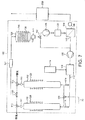
ガス混合物は、ガス混合物内に含まれる他のガスからキセノンガスを分離するためのガス分離システム100まで排出口ガス導管70によって運ばれる。図6に例示するように、ガス分離システム100は、ガス混合物の他の成分からキセノンを分離する機能を実施する加熱ガスクロマトグラフィーカラム102を含む。公知のように、ガスクロマトグラフィーカラムは、成分がカラムを通過する様々な速度に基づいてガスの成分を分離する。ガスクロマトグラフィーカラムは、当業技術で公知であり、従って本明細書で詳細に以下に説明しない。成分が特定のガスクロマトグラフィーカラムを進む速度は、いくつかの要因に依存し、以下を含む:
・成分の化学的及び物理的特性−比較的大きな分子は、比較的小さな分子よりもゆっくりカラムを通って進む、
・カラムの温度−カラム温度の上昇は、カラムを通過する成分の全てを加速する、
・カラムの長さ−カラムの長さの増大は、成分の分離を改善する、
・カラムを通るガスの流速−流速の低下は、成分の全てがカラムを通過する速度を低下させる、及び
・カラムの成分−カラムは、ガス混合物の成分を分離するための活性炭素の層、分子篩、又は他の材料を収容することができる。
The gas mixture is carried by an
The chemical and physical properties of the components-relatively large molecules travel through the column more slowly than relatively small molecules;
Column temperature-increasing the column temperature accelerates all of the components that pass through the column,
Column length-increasing column length improves component separation,
The flow rate of the gas through the column—the decrease in flow rate reduces the rate at which all of the components pass through the column; andthe component of the column—the column is a layer of activated carbon, molecular sieves for separating the components of the gas mixture Or other materials can be accommodated.
上記リストから、ガス内の成分の分離に最も大きく影響を与える要因は、成分の化学的及び物理的特性である。キセノン分子は、ガス混合物の他の成分のサイズと比較して比較的大きなサイズを有する。加えてキセノンは、電子の核から比較的長距離のシェル電子リングを有する大きな分子であるので、キセノンは、電子親和力を有し、そこでキセノンの分子は、弱いファン・デル・ワールス力の下でカラム内に時間的に保持される傾向がある。結果としてキセノンは、ガス混合物の多くの他の成分よりも遥かにゆっくりとカラム102の充填層を通って拡散する。例えば、ガス混合物の可能な成分のうち、He、Ar、O2、N2、CF4、及びCO2は、Xeよりも速くカラム102を通って拡散することになるが、C2F6は、Xeよりもゆっくりとカラム102を通って拡散することになる。
From the above list, the factors that have the greatest influence on the separation of components in the gas are the chemical and physical properties of the components. Xenon molecules have a relatively large size compared to the size of the other components of the gas mixture. In addition, since xenon is a large molecule with a shell electron ring that is relatively long distance from the electron nucleus, xenon has an electron affinity, where the xenon molecule is under weak van der Waals forces. There is a tendency to remain in the column in time. As a result, xenon diffuses through the packed bed of
カラム102の温度及びサイズ、並びにカラム102内へのガス混合物の流速は、従って、キセノンが依然としてカラム102内に保持される間中、多くの他の成分がカラム102の排出口108から出ていくように構成される。これらの要因は、好ましくはカラム102のサイズが最小にされるように、他の成分がカラム102から生成されるのに要する時間、及び従ってガス混合物の他の成分からキセノンを分離するのに要する時間もまた最小にされるように構成される。
キセノンがカラム102内に残っている間中、カラム102の排出口108から生成されるガス内の成分の性質に応じて、このガスは、例えば、排出口108から生成されるガスからCXF2X+2成分を除去するための三方弁110を用いてガス処理システムに運ぶか又は大気に放出することができる。
The temperature and size of the
While xenon remains in the
カラム102の排出口108に隣接して設けられた適切な検出器111を用いて検出することができる、ガス混合物の「より高速の」成分がカラム102から排出された状態で、「より低速の」キセノンが、カラム102から抽出される。図示の配置では、ヘリウム(又は水素)搬送ガスは、ヘリウムがヘリウム供給導管112に供給される加圧緩衝タンク116に制御されたヘリウムの量を供給する高純度ヘリウムの供給源114に接続した第2のヘリウム供給導管112からカラムに供給される。図6に例示するように、第2のヘリウム供給導管112は、カラム102からキセノンを追い出すために、弁118を通ってカラム102の吸気口106に搬送ガスの加圧流を供給する。必要に応じて、カラム102に入るガスの混合物のための搬送ガスを提供するために、ある程度のヘリウムもガス混合物と共に供給することができる。
With the “faster” components of the gas mixture being discharged from the
カラムを加熱するために、加熱器120が、カラム102の少なくとも一部の周囲に延びている。通常の使用では、カラム102は、約200℃の温度まで加熱される。カラム102の温度の上昇は、更に、カラムの充填層を再生するための技術として用いることができる。図7に例示するように、この場合には、第2のカラム122は、一方のカラムがカラムを再生するように約200℃の温度まで加熱され、他方のカラムが導管70からガス混合物を受け取るために200℃まで冷却されているように、第1のカラム102と並列で設けることができる。適切な弁124、126は、ガス流をカラムの1つに選択的に運ぶことができるように、キセノン及びヘリウム搬送ガスを含む排出ガスをカラムの1つから排出することができるようにカラム102、122から上流及び下流に設けられる。
A
図6に戻ると、搬送ガスをカラム102から追い出す間、三方弁110(又は、図7では三方弁126)は、カラム102から排出されたヘリウム及びキセノンのガス混合物を貯蔵容器128に向けるように切り換わる。熱交換機構127は、貯蔵容器128に入る前にカラム102から排出されたガス混合物を冷却するように、この三方弁と貯蔵容器128の間に設けることができる。
カラム102内への搬送ガスの流速は、好ましくは、キセノンを存在するC2F6のようなガス混合物の他の「より低速の」成分から離れてカラムから追い出することができるように選択される。この場合には、検出器111を用いて検出することができる、キセノンがカラム102から追い出された状態で、三方弁110は、排出口108から生成されるガスのC2F6及びあらゆる他の低速成分を処理することができるように、カラム102の排出口108から生成されるガスをガス処理システムに向け直して戻すように切り換わる。
Returning to FIG. 6, while the carrier gas is expelled from the
The flow rate of the carrier gas into the
CO2が貯蔵容器128に向って運ばれた排出ガス内に存在する場合には、図6に示すように、1つ又はそれよりも多くのCO2トラップ150を排出ガスからCO2を除去するためにカラム102と貯蔵容器128の間に設けることができる。キセノンの少なくとも一部と同様のカラムを通る通過速度を有するC2F6及びあらゆる細菌のような種は、キセノンがカラム102から現れ始める前に、例えば、ガス混合物からこれらの種を除去するために又はこれらの種をカラム102を通過することになる1つ又はそれよりも多くのより軽い種に変換するために導管70内で適切なプラズマ又は膜反応器152によりカラム102の吸気口106にガス混合物を供給する前に、ガス混合物から除去することができる。それによってカラム102から排出される希ガスを含むガスのその後の浄化を促進することができる。
If CO 2 is present in the exhaust gas carried toward the
貯蔵容器128は、著しい量のヘリウムガスが貯蔵容器128を通過することを可能にしながらガス混合物からキセノンを優先的に吸着するための吸着材料130を含む。1つの適切な吸着材料は、活性炭である。貯蔵容器128から排出口134に接続した弁132は、貯蔵容器128から排出されたヘリウムリッチなガス流を適切なコンプレッサ136を通じて加圧緩衝タンク116に向けて戻す。結果として貯蔵容器から排出されたヘリウムは、カラム102からキセノンを追い出すのに再利用するためのカラム102に再循環されて戻ることができる。更に、ヘリウムガスを有する貯蔵容器128から排出されるあらゆる非吸着キセノンは、ガス回収システム60から失われることなく、代わりにガス回収システム60内に保持される。
The
ヘリウムが貯蔵容器128から排出された状態で、弁132は、排出口を貯蔵容器128から、貯蔵容器から排出されたキセノンリッチなガス流を浄化するための分離器104に接続するように切り換わる。貯蔵容器128内の圧力は、吸着材料130からガスを脱着するコンプレッサ138によって低下する。図6に示すように、加熱器140は、ガス脱着のための吸着材料の再生を助ける吸着材料130を加熱するために貯蔵容器128の周囲に設けることができる。この場合には、2つの貯蔵容器は、一方の貯蔵容器が吸着材料からガスを脱着するように加熱され、他方の貯蔵容器がカラム102からガス流を受け取るために冷却されているように、次に、カラム102からガス流を受け取るために図4に例示する貯蔵容器と同様に設けることができる。逆圧調整器141は、貯蔵容器128内の圧力を制御するように、貯蔵容器128とコンプレッサ136、138の間に設けられる。
With helium being discharged from the
従って、コンプレッサ138から排出されたキセノンリッチなガスは、大部分はキセノンを含むが、同様に貯蔵容器128内の吸着材料130によって吸着された一般的に約10%Heのヘリウムの量を含むことになる。このガス混合物は、一般的に、5から10barの大気圧よりも大きな圧力でコンプレッサ138からガス混合物がガス分離器104に排出される貯蔵タンク180まで運ばれる。好ましい配置では、ガス分離器104は、膜装置を含む。ガス分離器としての膜装置104の使用の代替として、ガスの融点と沸点の間の差に起因して他のガスからキセノンを分離するための深冷分離器を含む。膜装置は、上述の他の装置に勝るこの分離器の購入及び作動に関連する低コストにより好ましいものである。
Thus, the xenon-rich gas exhausted from the
膜装置104は、ガス混合物の成分の1つが選択的に浸透する半透膜を含む。この実施例では、膜は、米国特許第6,168,649号に説明されている実施例のポリマー材料である。ガス混合物は、膜と接触させられる。貯蔵タンク180から排出されたガスの圧力の上昇は、膜にわたる圧力差をもたらす。ガス混合物内のヘリウム分子は、キセノン分子よりもより急速に膜を通って浸透する。それによってヘリウムを使い果たし、一般的に、0.5%よりも少ないHeを含む膜のより高圧力の側に第2のキセノンリッチなガス流をもたらす。従って、膜分離器104は、ヘリウムのキセノンリッチなガス流を浄化するのに役立つ。次に、キセノン希薄(すなわち、ヘリウム豊富)ガス流は、膜の低圧力側で得られる。第2のガス流は、貯蔵容器から排出されたヘリウムをカラム102からキセノンを追い出すのに再利用するためのカラム102まで排出して戻すことができるように、膜装置104の第1の排出口142から加圧緩衝タンク116まで運んで戻される。更に、ヘリウムガスを有する膜装置104から排出されるあらゆる非吸着キセノンは、ガス回収システム60から失われることなく、代わりにキセノン回収システム60内に保持される。
水素が搬送ガスとして用いられる場合には、貯蔵容器128なしで済ますことができ、カラム102からの排出ガスは、排出ガスをキセノンリッチなガス流とヘリウムリッチなガス流に分離するのに役立つ膜装置104まで直接運ばれる。
The
If hydrogen is used as the carrier gas, the
図6及び7に示す実施例では、搬送ガスは、カラム102の吸気口106に供給される。しかし、キセノン分子がカラム102を通って移動する速度に応じて、C2F6が同様にカラム102内に存在しないと、キセノンをカラム102から「バックフラッシュ」するようにカラム102の排出口108に搬送ガスを供給することにより、カラム102を急速にパージすることができる。搬送ガスをカラムの102の排出口に供給する配置は、図8に例示されている。この配置では、ガス分離システム100は、ヘリウムをカラムの吸気口106に供給するための第1のヘリウム供給導管112、及びヘリウムをカラム102の排出口108に供給するための第2のヘリウム供給導管146を含む。システム100は、排出ガスをカラム102の吸気口106から貯蔵容器128まで運ぶための第1の排出口ガス導管148と、排出ガスをカラム102の排出口108から貯蔵容器128まで運ぶための第2の排出口ガス導管150を更に含む。使用中、ガス導管70内の弁152は開かれ、第1のヘリウム供給導管112内の弁118、第1の排出口ガス導管148内の弁154、及び第2の排出ガス導管150内の弁156は、ガス混合物がカラム102の吸気口106を通ってガス導管70から運ばれるように閉じている。弁配置158は、ガス混合物からの高速ガスが必要に応じて大気に放出されるか又はガス処理システムに向けられるように、最初に切り換わる。キセノンをカラム102の排出口108から追い出すために、弁152、154は閉じ、弁156は開き、弁配置158は、排出ガスを第2の排出ガス導管150に向けるように切り換わる。キセノンをカラム102の吸気口106から追い出すために、交換ガスがカラム102の吸入口106から排出されて、第1の排出ガス導管148を通って貯蔵容器128まで運ばれるように、弁118、152、156は閉じ、弁154は開き、弁配置158は、搬送ガスをカラムの排出口108内に向けるように切り換わる。従って、この配置は、あらゆる好ましい方向のカラム102からキセノンを追い出すのに適切である。例えば、定期的にカラム102を洗浄し、従って、カラム102の層内又はカラム102の吸気口106又は排出口108のいずれかに閉じ込められたあらゆるキセノンを除去するために、搬送ガスは、カラム102を通って貯蔵容器128まで、及び次に貯蔵容器132の排出口134から緩衝タンク116までのいずれの方向にも運ばれる。このようにして、カラム102内に残っているあらゆるキセノンは、更にガス回収システム60内に保持される。搬送ガスの貯蔵容器128通過の代わりとして、パージガスを直接第1の排出ガス導管148から緩衝タンク116に戻るためのコンプレッサ136まで運ぶために、バイパス導管を設けることができる。
In the embodiment shown in FIGS. 6 and 7, the carrier gas is supplied to the
上述のように、ガス分離システム100は、キセノンをカラム102から追い出すためにヘリウム搬送ガスを用いる。ガス混合物内のキセノンを濃縮するために、このようなシステム100を図4及び5に示す配置と組み合わせて用いると、2つの別々の供給源を利用するのではなく、ヘリウム(又は水素)の単一供給源を利用することが明らかに望ましいものになる。ヘリウム(又は水素)ガスが、単一供給源78から、内部に含まれる吸着材料74を再生するための貯蔵容器62、64及びキセノンをカラム102から追い出すためのカラム102の両方に供給されるこのような配置が図9に示されている。この配置では、ヘリウム供給導管112は、搬送ガスを緩衝タンク80からカラム102に供給することができるように、ヘリウム供給導管82と流体連通している。コンプレッサ136は、貯蔵容器128の排出口から排出された搬送ガスを緩衝タンク80に戻すように、緩衝タンク80と流体連通している。導管170は、第1の排出口142から排出されたヘリウムリッチなガス流がガス回収システム内に保持されるように、第1の排出口142から排出されたヘリウムリッチなガス流をガス分離器104からガス混合物との結合及び/又は貯蔵容器62、64内の吸着材料74の再生の用途のための導管50まで運んで戻す。
As described above,
キセノンリッチなガス流は、膜装置104の第2の排出口144から貯蔵及び送出モジュール200まで運ばれる。図10を参照すると、貯蔵及び送出モジュール200は、キセノンリッチなガス流を圧縮し、圧縮したガス流をコンプレッサ202からガス流に移動したあらゆる水分を除去するための乾燥器204に排出するためのコンプレッサ202を含む。乾燥器204は、ゲル又はゼオライオトベース乾燥器とすることができる。ガス流は、乾燥器202から処理チャンバ10まで戻るキセノンを貯蔵するための貯蔵容器206まで通る。貯蔵容器206内のキセノンの量が所定の数値よりも下に低下する場合には、貯蔵容器206に直接フレッシュキセノンを供給するために、フレッシュキセノンの供給源208を設けることができる。貯蔵容器206及びキセノン供給源208は、図示のように、キセノン供給源18及び緩衝タンク20から分離することができる。代替的に、キセノン供給源18及び緩衝タンク20は省略することができ、キセノンは、貯蔵タンク206からチャンバ10に最初に供給されている。更に別の代替として、比較的不純なキセノンは、この比較的不純なキセノンが貯蔵容器206に達する前にガス回収システム60によって浄化されるように、例えば、カラム102から上流のガス回収システム60に供給することができる。
A xenon-rich gas stream is conveyed from the
貯蔵容器206から生成されるキセノンは、ガス流内に残るC2F6及び炭化水素のようなあらゆる不純物と反応するゲッタ材料を収容するガス研磨機210を通過する。ガス研磨機210は、微量のヘリウムを有する少なくとも99.9%の純度、より典型的には、少なくとも99.99%純度のキセノンを含むガス流を生成する。
ガス研磨機210から生成されるキセノンの純度を検査することを可能にするために、貯蔵容器206から生成されるキセノンの純度を検出するための適切な検出器216を含む再循環導管214にキセノンの一部を選択的に送出する弁212が設けられる。図10に示すように、キセノンは、検出器216が正確に測定することができるように、弁配置212を通じてキセノン供給源208から再循環導管214まで選択的に運ぶことができる。キセノンは、再循環導管214を通過するあらゆるキセノンがモジュール200内に保持されて更に別の浄化を受けるように、検出器216からコンプレッサ202まで運んで戻される。貯蔵容器206から生成されるキセノンの純度が所定のレベルよりも小さい場合には、コントローラ23は、キセノン供給源208をモジュール200と質量流量コントローラ22の間に延びるガス導管252に接続するように弁配置212を制御する。コントローラ23は、フレッシュキセノンを貯蔵容器206に供給するために、貯蔵及び送出モジュール200内の弁220を開くことができ、それによって貯蔵容器208内のキセノンの純度を増大させる。弁配置212は、貯蔵容器206から生成されるキセノンの純度を継続的に再評価することができるように、キセノンを貯蔵容器206から再循環導管214まで運搬し続けるように制御することができる。純度が所定のレベルに等しいか又はそれよりも大きくなる場合には、弁配置212は、キセノンを貯蔵タンクから供給するように制御される。キセノンの純度が、例えば、システム60の成分の1つの障害に起因して大きく阻害される場合には、キセノンは、三方弁218を用いて大気に貯蔵容器206から放出することができ、貯蔵容器206は、その後にキセノン供給源から充填され、それによってシステム60によってチャンバに戻るキセノンの純度を維持する。
The xenon produced from the
In order to be able to inspect the purity of the xenon produced from the
上述の事項は、本発明の一実施形態を表し、その他は、本明細書の特許請求の範囲によって定められた本発明の真の範囲から逸脱することなく当業者に想起されることになることは理解されるものとする。
例えば、ガス回収システム60は、複数の処理チャンバ10に供給された希ガスを回収するのに用いることができる。図11は、ガス回収システム60が、4つの処理チャンバ10に供給された希ガスの回収に設けられた実施例を例示する図である。この実施例では、ガスは、それぞれのポンプシステム26を用いて処理チャンバ10の各々から排出され、ポンプシステム26の各々が、共通の除去装置40にガスを排出する。除去装置40及びガス回収システム60は、ガス流の増加時に対処するようにサイズが拡大縮小される。
The foregoing represents one embodiment of the invention and others will occur to those skilled in the art without departing from the true scope of the invention as defined by the claims herein. Should be understood.
For example, the
前の実施例では、単一希ガス、すなわち、キセノンが、ガス混合物から分離される。図12は、ガスの混合物、例えば、キセノン及びクリプトンの混合物をガス混合物から回収することができるように、ガス回収システムを修正することができる方法を例示する図である。図示のように、ガス回収システム100は、カラム102からの排出ガスが第1の貯蔵容器128内に運ばれる第1の位置と、カラム102からの排出ガスが第1の貯蔵容器128と同様である第2の貯蔵容器262内に運ばれる第2の位置との間で移動することができる三方弁260を含む。それによってキセノンがカラム102から排出された時にキセノン及びヘリウム搬送ガスを含む排出ガスを第1の貯蔵容器128まで運搬し、クリプトンがカラム102から排出された時にクリプトン及びヘリウム搬送ガスを含む排出ガスを第2の貯蔵容器262まで運ぶことができる。各貯蔵容器128、262の排出口134は、貯蔵容器128、262から排出されたヘリウムリッチなガス流を緩衝タンク116まで運ぶことができ、かつ次に貯蔵容器128、262から排出された希ガスリッチなガス流をヘリウムから希ガスリッチなガス流を浄化するためのそれぞれのガス分離器104まで各々運ぶことができるように、それぞれの三方弁132に接続される。図示のように、ガス分離器104から排出された2つの浄化された希ガスリッチなガス流は、貯蔵及び送出モジュール200まで運ばれる前に組み合わせることができる。ガス分離器104から排出された希ガス希薄ガス流は、緩衝タンク116まで運ぶことができる。
In the previous embodiment, a single noble gas, xenon, is separated from the gas mixture. FIG. 12 is a diagram illustrating a method by which a gas recovery system can be modified so that a mixture of gases, eg, a mixture of xenon and krypton, can be recovered from the gas mixture. As shown, the
100 ガス分離システム
102 加熱ガスクロマトグラフィーカラム
106 吸気口
112 第2のヘリウム供給導管
118 弁
100
Claims (42)
ガスクロマトグラフィーカラムにガス混合物を供給して該ガス混合物の成分を分離し、かつそこから連続的に該成分を排出する段階と、
搬送ガスを前記カラムに供給する段階と、
カラムから排出された前記搬送ガスと前記希ガスとを含む排出ガスを希ガスリッチなガス流と搬送ガスリッチなガス流に分離する段階と、
前記希ガスリッチなガス流を浄化する段階と、
を含むことを特徴とする方法。 A method of recovering a noble gas from a gas mixture containing a plurality of components, one of which is a noble gas,
Supplying a gas mixture to a gas chromatography column to separate components of the gas mixture and continuously discharging the components therefrom;
Supplying a carrier gas to the column;
Separating the exhaust gas comprising the carrier gas and the rare gas discharged from the column into a rare gas rich gas stream and a carrier gas rich gas stream;
Purifying the noble gas-rich gas stream;
A method comprising the steps of:
ガスクロマトグラフィーカラムにガス混合物を供給して該ガス混合物の成分を分離し、かつそこから連続的に該成分を排出する段階と、
搬送ガスを前記カラムに供給する段階と、
カラムから排出された前記搬送ガスと前記希ガスとを含む排出ガスを希ガスリッチなガス流と搬送ガスリッチなガス流に分離する段階と、
を含み、
前記ガス混合物は、そうでなければ前記希ガスの少なくとも一部と共に前記カラムを通って進むであろう1つ又はそれよりも多くの成分を該ガス混合物から除去するために、該カラムへの該ガス混合物の供給の前に処理される、
ことを特徴とする方法。 A method of recovering a noble gas from a gas mixture containing a plurality of components, one of which is a noble gas,
Supplying a gas mixture to a gas chromatography column to separate components of the gas mixture and continuously discharging the components therefrom;
Supplying a carrier gas to the column;
Separating the exhaust gas comprising the carrier gas and the rare gas discharged from the column into a rare gas rich gas stream and a carrier gas rich gas stream;
Including
The gas mixture is supplied to the column to remove one or more components from the gas mixture that would otherwise travel through the column with at least a portion of the noble gas. Processed before supply of gas mixture,
A method characterized by that.
ガス混合物の成分を分離し、かつ連続的に該成分を排出するためのガスクロマトグラフィーカラムと、
搬送ガスを前記カラムに供給するための手段と、
カラムから排出された前記搬送ガスと前記希ガスとを含む排出ガスを希ガスリッチなガス流と搬送ガスリッチなガス流に分離するための手段と、
前記希ガスリッチなガス流を浄化するための手段と、
を含むことを特徴とする機器。 An apparatus for recovering a rare gas from a gas mixture containing a plurality of components, one of which is a rare gas,
A gas chromatography column for separating the components of the gas mixture and continuously discharging the components;
Means for supplying a carrier gas to the column;
Means for separating the exhaust gas comprising the carrier gas and the rare gas discharged from the column into a rare gas rich gas stream and a carrier gas rich gas stream;
Means for purifying the rare gas rich gas stream;
A device characterized by including.
ガス混合物の成分を分離し、かつ連続的に該成分を排出するためのガスクロマトグラフィーカラムと、
搬送ガスを前記カラムに供給するための手段と、
カラムから排出された前記搬送ガスと前記希ガスとを含む排出ガスを希ガスリッチなガス流と搬送ガスリッチなガス流に分離するための手段と、
そうでなければ前記希ガスの少なくとも一部と共に前記カラムを通って進むであろう1つ又はそれよりも多くの成分を前記ガス混合物から除去するために該カラムへの該ガス混合物の供給の前に該ガス混合物を処理するための手段と、
を含むことを特徴とする機器。 An apparatus for recovering a rare gas from a gas mixture containing a plurality of components, one of which is a rare gas,
A gas chromatography column for separating the components of the gas mixture and continuously discharging the components;
Means for supplying a carrier gas to the column;
Means for separating the exhaust gas comprising the carrier gas and the rare gas discharged from the column into a rare gas rich gas stream and a carrier gas rich gas stream;
Prior to feeding the gas mixture to the column to remove one or more components from the gas mixture that would otherwise travel through the column with at least a portion of the noble gas. Means for treating the gas mixture;
A device characterized by including.
Applications Claiming Priority (2)
| Application Number | Priority Date | Filing Date | Title |
|---|---|---|---|
| US11/019,843 US7368000B2 (en) | 2004-12-22 | 2004-12-22 | Treatment of effluent gases |
| PCT/GB2005/004839 WO2006067384A1 (en) | 2004-12-22 | 2005-12-15 | Method of recovering a noble gas from a gas mixture |
Publications (2)
| Publication Number | Publication Date |
|---|---|
| JP2008525779A true JP2008525779A (en) | 2008-07-17 |
| JP2008525779A5 JP2008525779A5 (en) | 2009-02-12 |
Family
ID=36051545
Family Applications (1)
| Application Number | Title | Priority Date | Filing Date |
|---|---|---|---|
| JP2007547615A Pending JP2008525779A (en) | 2004-12-22 | 2005-12-15 | Method for recovering noble gases from gas mixtures |
Country Status (6)
| Country | Link |
|---|---|
| US (1) | US7368000B2 (en) |
| EP (1) | EP1841690A1 (en) |
| JP (1) | JP2008525779A (en) |
| KR (1) | KR20070086519A (en) |
| TW (1) | TWI399236B (en) |
| WO (1) | WO2006067384A1 (en) |
Cited By (2)
| Publication number | Priority date | Publication date | Assignee | Title |
|---|---|---|---|---|
| JP2009297709A (en) * | 2008-05-28 | 2009-12-24 | L'air Liquide-Sa Pour L'etude & L'exploitation Des Procedes Georges Claude | Plasma processing system for fluid or fluid mixture |
| KR20140111335A (en) * | 2012-01-10 | 2014-09-18 | 알스톰 테크놀러지 리미티드 | A method for filtration of gas effluents from an industrial installation |
Families Citing this family (46)
| Publication number | Priority date | Publication date | Assignee | Title |
|---|---|---|---|---|
| US20050250347A1 (en) * | 2003-12-31 | 2005-11-10 | Bailey Christopher M | Method and apparatus for maintaining by-product volatility in deposition process |
| WO2005072852A1 (en) * | 2004-01-29 | 2005-08-11 | Taiyo Nippon Sanso Corporation | Method and apparatus for treating exhaust gas |
| GB0521944D0 (en) | 2005-10-27 | 2005-12-07 | Boc Group Plc | Method of treating gas |
| DE102006034601B3 (en) * | 2006-07-26 | 2008-02-07 | Schmidt, Klaus, Prof. Dr. | Retention of noble gases in the respiratory gas in ventilated patients by means of membrane separation |
| GB0618016D0 (en) * | 2006-09-13 | 2006-10-18 | Boc Group Plc | Method of recycling hydrogen |
| US20080072953A1 (en) * | 2006-09-27 | 2008-03-27 | Thinsilicon Corp. | Back contact device for photovoltaic cells and method of manufacturing a back contact device |
| JP5202836B2 (en) * | 2006-12-01 | 2013-06-05 | 日本エア・リキード株式会社 | Xenon recovery system and recovery device |
| US20080295882A1 (en) * | 2007-05-31 | 2008-12-04 | Thinsilicon Corporation | Photovoltaic device and method of manufacturing photovoltaic devices |
| WO2009055750A1 (en) * | 2007-10-26 | 2009-04-30 | Applied Materials, Inc. | Methods and apparatus for smart abatement using an improved fuel circuit |
| CN101939079B (en) * | 2008-02-05 | 2013-06-12 | 应用材料公司 | Systems and methods for treating flammable effluent gases from manufacturing processes |
| US20090222128A1 (en) * | 2008-02-05 | 2009-09-03 | Applied Materials, Inc. | Methods and apparatus for operating an electronic device manufacturing system |
| US8340827B2 (en) * | 2008-06-20 | 2012-12-25 | Lam Research Corporation | Methods for controlling time scale of gas delivery into a processing chamber |
| US8021468B2 (en) * | 2008-06-23 | 2011-09-20 | Siemens Medical Solutions Usa, Inc. | Room temperature chemical trap for the purification of gaseous methane |
| US8042566B2 (en) * | 2008-07-23 | 2011-10-25 | Atmel Corporation | Ex-situ component recovery |
| WO2010037102A2 (en) * | 2008-09-29 | 2010-04-01 | Thinsilicon Corporation | Monolithically-integrated solar module |
| US8444766B2 (en) * | 2008-12-10 | 2013-05-21 | Thinsilicon Corporation | System and method for recycling a gas used to deposit a semiconductor layer |
| GB2469647B (en) | 2009-04-21 | 2014-03-05 | Linde Ag | Lasers |
| CN102272944B (en) * | 2009-05-06 | 2013-08-14 | 薄膜硅公司 | Photovoltaic cells and methods to enhance light trapping in semiconductor layer stacks |
| US20110114156A1 (en) * | 2009-06-10 | 2011-05-19 | Thinsilicon Corporation | Photovoltaic modules having a built-in bypass diode and methods for manufacturing photovoltaic modules having a built-in bypass diode |
| JP2012522404A (en) * | 2009-06-10 | 2012-09-20 | シンシリコン・コーポレーション | Photovoltaic module and method of manufacturing a photovoltaic module having multiple semiconductor layer stacks |
| US8535414B2 (en) * | 2010-09-30 | 2013-09-17 | Air Products And Chemicals, Inc. | Recovering of xenon by adsorption process |
| US8920573B2 (en) * | 2011-09-14 | 2014-12-30 | Institute Of Nuclear Energy Research, Atomic Energy Council | Method of improving purity and yield of chemical product in automatic radioactive medicine synthesis system |
| CN102832096B (en) * | 2012-09-20 | 2015-11-25 | 中微半导体设备(上海)有限公司 | A kind of gas supply device for vacuum treatment installation and gas supply thereof and changing method |
| US10076620B2 (en) | 2012-12-22 | 2018-09-18 | Dmf Medical Incorporated | Anesthetic circuit having a hollow fiber membrane |
| JP6368458B2 (en) * | 2013-05-24 | 2018-08-01 | 株式会社荏原製作所 | Vacuum pump with abatement function |
| JP6441660B2 (en) * | 2014-03-17 | 2018-12-19 | 株式会社荏原製作所 | Vacuum pump with abatement function |
| JP6472653B2 (en) * | 2014-03-17 | 2019-02-20 | 株式会社荏原製作所 | Vacuum pump with abatement function |
| CN104383784B (en) * | 2014-11-27 | 2016-03-02 | 中国科学技术大学 | The system and method for separation and Extraction inert gas from environmental gas |
| TWI547305B (en) * | 2014-12-18 | 2016-09-01 | 財團法人工業技術研究院 | Hollow fiber adsorbent compressed dry air system |
| JP6175471B2 (en) * | 2015-10-30 | 2017-08-02 | 日本エア・リキード株式会社 | Neon recovery and purification system and neon recovery and purification method |
| JP6734061B2 (en) * | 2016-01-29 | 2020-08-05 | アジレント・テクノロジーズ・インクAgilent Technologies, Inc. | Plasma spectroscopy analyzer |
| US10677713B1 (en) * | 2016-08-04 | 2020-06-09 | Hrl Laboratories, Llc | Adaptive gas analyzer |
| CN107632099A (en) * | 2017-08-31 | 2018-01-26 | 天津市鹏翔科技有限公司 | A kind of intelligent online continuous sampling automatic analysis system and method |
| US10773203B2 (en) * | 2017-09-27 | 2020-09-15 | U.S. Department Of Energy | Transition group metals for the capture of radioactive xenon |
| US10824049B1 (en) | 2017-10-06 | 2020-11-03 | Hrl Laboratories, Llc | Optical-frequency up-converting spectrometric imager |
| JP7096004B2 (en) | 2018-02-07 | 2022-07-05 | 株式会社Screenホールディングス | Board processing method and board processing equipment |
| JP7020951B2 (en) * | 2018-02-09 | 2022-02-16 | 東京エレクトロン株式会社 | Plasma processing system and plasma processing method |
| CN108899104B (en) * | 2018-07-26 | 2020-12-04 | 中国核动力研究设计院 | Is used for preparing85Method of Kr standard source |
| CN109665505B (en) * | 2018-12-21 | 2020-11-06 | 北京放射性核素实验室 | Atmospheric xenon enrichment and purification method and device |
| CN109665506B (en) * | 2018-12-21 | 2020-11-06 | 北京放射性核素实验室 | Atmospheric xenon enrichment and purification method and device |
| US11557462B2 (en) * | 2019-03-13 | 2023-01-17 | Kla Corporation | Collecting and recycling rare gases in semiconductor processing equipment |
| KR102368202B1 (en) * | 2020-02-19 | 2022-03-02 | (주)한양기술공업 | System and method for gas capture |
| WO2021167218A1 (en) * | 2020-02-19 | 2021-08-26 | (주)한양기술공업 | Gas collecting system and gas collecting method |
| GB2597545A (en) * | 2020-07-28 | 2022-02-02 | Edwards Ltd | A noble gas recovery system |
| US20230277974A1 (en) * | 2020-07-28 | 2023-09-07 | Edwards Limited | A noble gas recovery system |
| TWI808870B (en) * | 2022-08-11 | 2023-07-11 | 印能科技股份有限公司 | Gas Recovery Equipment |
Citations (4)
| Publication number | Priority date | Publication date | Assignee | Title |
|---|---|---|---|---|
| JPS58190799A (en) * | 1982-04-21 | 1983-11-07 | フォルシュングスツエントルム・ユーリッヒ・ゲゼルシャフト・ミト・ベシュレンクテル・ハフツング | Method and device for seperating krypton from radioactive gaseous waste |
| DE19641643A1 (en) * | 1996-10-09 | 1998-04-16 | Linde Ag | Production of pure xenon in an air separation plant |
| US6565821B1 (en) * | 1999-09-06 | 2003-05-20 | L'Air Liquide - Société Anonyme Á Directoire et Conseil de Surveillance pour l'Etude et l'Exploitation des Procédés Georges Claude | Process for removing the fluorocompounds or fluorosulphur compounds from a stream of xenon and/or krypton by permeation |
| US20030221448A1 (en) * | 2002-05-28 | 2003-12-04 | Kazuo Shoji | Method of producing high-purity helium |
Family Cites Families (13)
| Publication number | Priority date | Publication date | Assignee | Title |
|---|---|---|---|---|
| DE1619936A1 (en) | 1967-06-12 | 1971-03-25 | Leuna Werke Veb | Process for the industrial production of pure gases |
| US3683589A (en) * | 1970-09-08 | 1972-08-15 | Us Interior | Helium purifier |
| US3890121A (en) * | 1974-02-19 | 1975-06-17 | Us Energy | Noble gas absorption process |
| US4093429A (en) * | 1975-12-19 | 1978-06-06 | General Electric Company | Gas separation system |
| US4238204A (en) * | 1979-06-18 | 1980-12-09 | Monsanto Company | Selective adsorption process |
| FR2510539A1 (en) | 1981-07-28 | 1983-02-04 | Expertises Sa Cie Maritime | PROCESS AND PLANT FOR PURIFYING THE HELIUM CONTAINED IN A GAS MIXTURE |
| DD257996A1 (en) * | 1986-04-29 | 1988-07-06 | Dresden Komplette Chemieanlag | METHOD FOR SEPARATING A CRYPTONE XENONE MIXTURE |
| US4747854A (en) * | 1986-05-22 | 1988-05-31 | Air Products And Chemicals, Inc. | Selective chromatographic process using an ion-exchanged, dehydrated chabazite adsorbent |
| GB8813270D0 (en) | 1988-06-04 | 1988-07-06 | Plasma Products Ltd | Dry exhaust gas conditioning |
| US5457720A (en) * | 1994-04-15 | 1995-10-10 | General Electric Company | System for krypton-xenon concentration, separation and measurement for rapid detection of defective nuclear fuel bundles |
| US6168649B1 (en) * | 1998-12-09 | 2001-01-02 | Mg Generon, Inc. | Membrane for separation of xenon from oxygen and nitrogen and method of using same |
| JP4652860B2 (en) * | 2004-04-27 | 2011-03-16 | 大陽日酸株式会社 | How to recover krypton or xenon |
| US7285154B2 (en) * | 2004-11-24 | 2007-10-23 | Air Products And Chemicals, Inc. | Xenon recovery system |
-
2004
- 2004-12-22 US US11/019,843 patent/US7368000B2/en not_active Expired - Fee Related
-
2005
- 2005-12-15 KR KR1020077014130A patent/KR20070086519A/en not_active Application Discontinuation
- 2005-12-15 WO PCT/GB2005/004839 patent/WO2006067384A1/en active Application Filing
- 2005-12-15 EP EP05821460A patent/EP1841690A1/en not_active Withdrawn
- 2005-12-15 JP JP2007547615A patent/JP2008525779A/en active Pending
- 2005-12-22 TW TW094145911A patent/TWI399236B/en not_active IP Right Cessation
Patent Citations (4)
| Publication number | Priority date | Publication date | Assignee | Title |
|---|---|---|---|---|
| JPS58190799A (en) * | 1982-04-21 | 1983-11-07 | フォルシュングスツエントルム・ユーリッヒ・ゲゼルシャフト・ミト・ベシュレンクテル・ハフツング | Method and device for seperating krypton from radioactive gaseous waste |
| DE19641643A1 (en) * | 1996-10-09 | 1998-04-16 | Linde Ag | Production of pure xenon in an air separation plant |
| US6565821B1 (en) * | 1999-09-06 | 2003-05-20 | L'Air Liquide - Société Anonyme Á Directoire et Conseil de Surveillance pour l'Etude et l'Exploitation des Procédés Georges Claude | Process for removing the fluorocompounds or fluorosulphur compounds from a stream of xenon and/or krypton by permeation |
| US20030221448A1 (en) * | 2002-05-28 | 2003-12-04 | Kazuo Shoji | Method of producing high-purity helium |
Cited By (3)
| Publication number | Priority date | Publication date | Assignee | Title |
|---|---|---|---|---|
| JP2009297709A (en) * | 2008-05-28 | 2009-12-24 | L'air Liquide-Sa Pour L'etude & L'exploitation Des Procedes Georges Claude | Plasma processing system for fluid or fluid mixture |
| KR20140111335A (en) * | 2012-01-10 | 2014-09-18 | 알스톰 테크놀러지 리미티드 | A method for filtration of gas effluents from an industrial installation |
| KR101687461B1 (en) | 2012-01-10 | 2016-12-19 | 제네럴 일렉트릭 테크놀러지 게엠베하 | A method for filtration of gas effluents from an industrial installation |
Also Published As
| Publication number | Publication date |
|---|---|
| TW200640555A (en) | 2006-12-01 |
| EP1841690A1 (en) | 2007-10-10 |
| US20060130649A1 (en) | 2006-06-22 |
| WO2006067384A1 (en) | 2006-06-29 |
| TWI399236B (en) | 2013-06-21 |
| US7368000B2 (en) | 2008-05-06 |
| KR20070086519A (en) | 2007-08-27 |
Similar Documents
| Publication | Publication Date | Title |
|---|---|---|
| US7368000B2 (en) | Treatment of effluent gases | |
| KR100878946B1 (en) | Method and apparatus for feeding gases | |
| US7594955B2 (en) | Process for recovering rare gases using gas-recovering container | |
| EP1334758B1 (en) | Gas separating and purifying method and its apparatus | |
| US7285154B2 (en) | Xenon recovery system | |
| JP2008525779A5 (en) | ||
| JP7198676B2 (en) | Rare gas recovery system and rare gas recovery method | |
| EP2531274A1 (en) | Inert gas recovery system and method | |
| JPH1154851A (en) | Excimer laser gas recovery device | |
| JP4430913B2 (en) | Gas supply method and apparatus | |
| JP5584887B2 (en) | Ozone gas concentration method and apparatus | |
| JP5116195B2 (en) | Gas separation and purification method | |
| JP3869831B2 (en) | Gas separation method and apparatus | |
| JP2004339187A (en) | Method for purification and film-forming of perfluoro-compound | |
| JP2002137909A (en) | Helium gas refining method | |
| WO2021094709A1 (en) | Inert gas recovery from a semiconductor manufacturing tool | |
| JP2011117032A (en) | Fluorine gas generating apparatus | |
| KR101912348B1 (en) | Apparatus for manufacturing noble gases | |
| JP2000117052A (en) | Process and device for recovering fluoride | |
| JP2020006324A (en) | Gas separator and gas separation method | |
| JP2006507121A (en) | Gas supply and recovery for metal atomizers |
Legal Events
| Date | Code | Title | Description |
|---|---|---|---|
| A521 | Written amendment |
Free format text: JAPANESE INTERMEDIATE CODE: A523 Effective date: 20081215 |
|
| A621 | Written request for application examination |
Free format text: JAPANESE INTERMEDIATE CODE: A621 Effective date: 20081215 |
|
| A131 | Notification of reasons for refusal |
Free format text: JAPANESE INTERMEDIATE CODE: A131 Effective date: 20111107 |
|
| A02 | Decision of refusal |
Free format text: JAPANESE INTERMEDIATE CODE: A02 Effective date: 20120409 |