JP2008520487A - Spoke wheel rim for tubeless tires - Google Patents
Spoke wheel rim for tubeless tires Download PDFInfo
- Publication number
- JP2008520487A JP2008520487A JP2007541782A JP2007541782A JP2008520487A JP 2008520487 A JP2008520487 A JP 2008520487A JP 2007541782 A JP2007541782 A JP 2007541782A JP 2007541782 A JP2007541782 A JP 2007541782A JP 2008520487 A JP2008520487 A JP 2008520487A
- Authority
- JP
- Japan
- Prior art keywords
- rim
- sealing device
- relief
- sealing
- bed
- Prior art date
- Legal status (The legal status is an assumption and is not a legal conclusion. Google has not performed a legal analysis and makes no representation as to the accuracy of the status listed.)
- Pending
Links
Images


Classifications
-
- B—PERFORMING OPERATIONS; TRANSPORTING
- B60—VEHICLES IN GENERAL
- B60B—VEHICLE WHEELS; CASTORS; AXLES FOR WHEELS OR CASTORS; INCREASING WHEEL ADHESION
- B60B1/00—Spoked wheels; Spokes thereof
- B60B1/02—Wheels with wire or other tension spokes
- B60B1/04—Attaching spokes to rim or hub
- B60B1/041—Attaching spokes to rim or hub of bicycle wheels
-
- B—PERFORMING OPERATIONS; TRANSPORTING
- B60—VEHICLES IN GENERAL
- B60B—VEHICLE WHEELS; CASTORS; AXLES FOR WHEELS OR CASTORS; INCREASING WHEEL ADHESION
- B60B1/00—Spoked wheels; Spokes thereof
- B60B1/02—Wheels with wire or other tension spokes
- B60B1/04—Attaching spokes to rim or hub
- B60B1/043—Attaching spokes to rim
- B60B1/044—Attaching spokes to rim by the use of spoke nipples
-
- B—PERFORMING OPERATIONS; TRANSPORTING
- B60—VEHICLES IN GENERAL
- B60B—VEHICLE WHEELS; CASTORS; AXLES FOR WHEELS OR CASTORS; INCREASING WHEEL ADHESION
- B60B21/00—Rims
- B60B21/02—Rims characterised by transverse section
- B60B21/025—Rims characterised by transverse section the transverse section being hollow
-
- B—PERFORMING OPERATIONS; TRANSPORTING
- B60—VEHICLES IN GENERAL
- B60B—VEHICLE WHEELS; CASTORS; AXLES FOR WHEELS OR CASTORS; INCREASING WHEEL ADHESION
- B60B21/00—Rims
- B60B21/02—Rims characterised by transverse section
- B60B21/026—Rims characterised by transverse section the shape of rim well
-
- B—PERFORMING OPERATIONS; TRANSPORTING
- B60—VEHICLES IN GENERAL
- B60B—VEHICLE WHEELS; CASTORS; AXLES FOR WHEELS OR CASTORS; INCREASING WHEEL ADHESION
- B60B21/00—Rims
- B60B21/02—Rims characterised by transverse section
- B60B21/028—Rims characterised by transverse section the shape of hump
-
- B—PERFORMING OPERATIONS; TRANSPORTING
- B60—VEHICLES IN GENERAL
- B60B—VEHICLE WHEELS; CASTORS; AXLES FOR WHEELS OR CASTORS; INCREASING WHEEL ADHESION
- B60B21/00—Rims
- B60B21/02—Rims characterised by transverse section
- B60B21/04—Rims characterised by transverse section with substantially radial flanges
-
- B—PERFORMING OPERATIONS; TRANSPORTING
- B60—VEHICLES IN GENERAL
- B60B—VEHICLE WHEELS; CASTORS; AXLES FOR WHEELS OR CASTORS; INCREASING WHEEL ADHESION
- B60B21/00—Rims
- B60B21/06—Rims characterised by means for attaching spokes, i.e. spoke seats
- B60B21/062—Rims characterised by means for attaching spokes, i.e. spoke seats for bicycles
-
- B—PERFORMING OPERATIONS; TRANSPORTING
- B60—VEHICLES IN GENERAL
- B60B—VEHICLE WHEELS; CASTORS; AXLES FOR WHEELS OR CASTORS; INCREASING WHEEL ADHESION
- B60B21/00—Rims
- B60B21/06—Rims characterised by means for attaching spokes, i.e. spoke seats
- B60B21/068—Rims characterised by means for attaching spokes, i.e. spoke seats the spoke seat comprising sealing means, e.g. for tubeless racing bike tyres
-
- B—PERFORMING OPERATIONS; TRANSPORTING
- B60—VEHICLES IN GENERAL
- B60B—VEHICLE WHEELS; CASTORS; AXLES FOR WHEELS OR CASTORS; INCREASING WHEEL ADHESION
- B60B21/00—Rims
- B60B21/12—Appurtenances, e.g. lining bands
Abstract
Description
本発明は、リムのウェルにおいてリムベッド領域に配置される封止装置を含むチューブレスタイヤ用スポークホイールリムに関し、請求項1の前提部分に記載するように、リムはリム中心面の両側に封止部分を備えたレリーフを含む。
The present invention relates to a spoke wheel rim for a tubeless tire comprising a sealing device arranged in the rim bed region in the rim well, as described in the premise part of
本発明はまた、請求項23の前提部分に記載するように、チューブレスタイヤ用スポークホイールリム、及び請求項31の前提部分に記載するように、チューブレスタイヤを備えたスポークホイールリム用封止装置に関する。
The present invention also relates to a spoke wheel rim for a tubeless tire as described in the premise part of
上述のような、封止装置及びリムを含むチューブレスタイヤ用スポークホイールリム、並びに封止装置自体は、とりわけ自動二輪車及び自転車で使用するために供給されるが、またスポークホイールを使用する他の車両で使用するためにも供給される。このようなスポークホイールでは、複数のスポークはリム及びホイールハブの間に延出する。 Spoke wheel rims for tubeless tires, including sealing devices and rims, as described above, and the sealing devices themselves are supplied for use in motorcycles and bicycles, among others, but also other vehicles that use spoke wheels Also supplied for use in. In such a spoke wheel, the plurality of spokes extend between the rim and the wheel hub.
含まれるリムは通常、打ち抜きリムと呼ばれるものであり、即ちスポークニップルを受入れ且つ配向するための凹部を特色とする。それ故、所謂打ち抜き穴は、リム及びリム上に載置されるタイヤの間に形成される空間が開放し、従って気密的でないことを保証する。このため、チューブが通常、このようなスポークホイールに用いられる。かかる周知のチューブを備えたスポークホイールは、多くの欠点を有する。 The included rims are usually called punched rims, i.e. feature a recess for receiving and orienting the spoke nipple. The so-called punched holes therefore ensure that the space formed between the rim and the tire mounted on the rim is open and therefore not airtight. For this reason, tubes are usually used for such spoke wheels. Spoke wheels with such known tubes have a number of disadvantages.
通常、リムベッド及びチューブの間に嵌合されるのは、スポークニップルや、タイヤ、チューブ、リムバンド及びリムの結合物におけるチューブの破損を阻止するように構成されたリムバンドであり、その結果、このように形成されたスポークホイールでは、高質量が生じる。ホイールハブから見ると、半径方向外方への質量集中に起因して、これはもはや、このように形成されたスポークホイールの高速慣性回転運動をもたらし、例えば意図的に方向を変化させる時に、このようなスポークホイールが嵌合された自動二輪車の操作機敏性を失う。更に、チューブはまた蛇の噛み傷のような破損を受け易い、即ちオフロードバイクでのジャンプ、続く着地の後で、チューブがリムベッドに押し潰されてその結果2個の穴が作られた後に、2個の穴がチューブの下側に生じる。また、このようなチューブを備えたスポークホイールに設けられる必要があるのは、リムに対してタイヤが所定位置から捩れ出るのを阻止する任務を有するリム上の所謂タイヤホルダである。タイヤの捩れは、捩れたタイヤがチューブと「同調」し、従ってチューブに嵌合された弁がチューブをスポークリムを通るように押し付けて、チューブを剪断するという問題が付随することが多い。 Usually fitted between the rim bed and the tube is a spoke nipple or a rim band configured to prevent tube breakage in the tire, tube, rim band and rim combination. In the spoke wheel formed in a high mass occurs. When viewed from the wheel hub, due to the mass concentration radially outward, this no longer results in a high-speed inertial rotation of the spoke wheel thus formed, e.g. when intentionally changing direction. The operation agility of a motorcycle fitted with such a spoke wheel is lost. In addition, the tube is also susceptible to breakage such as a snake bite, ie after an off-road bike jump, subsequent landing, after the tube is crushed into the rim bed, resulting in two holes. Two holes are created on the underside of the tube. Also, what is needed to be provided on a spoke wheel with such a tube is a so-called tire holder on the rim that has the task of preventing the tire from twisting out of position with respect to the rim. Tire twisting is often accompanied by the problem that the twisted tire "synchronizes" with the tube, so that a valve fitted to the tube pushes the tube through the spoke rim and shears the tube.
これらの問題を回避するために、弁に嵌合させるための穴を除き、リムベッドに開口を含まないように特別に形成されたリムを必要とするチューブレスタイヤが既に知られている。これにより、かかるチューブレスリム上において、例えば鋳造リムとしてリムベッドと一体的に製造される必要もあるスポークが結果的に得られ、このリムも同様に、重くまた製造に起因して鋳造の間に破壊し易く、従って高負荷には不適切である。 In order to avoid these problems, tubeless tires are already known that require a rim that is specially formed so as not to include an opening in the rim bed, except for a hole for fitting the valve. This results in spokes on such tubeless rims that also need to be produced integrally with the rim bed, for example as a cast rim, which is likewise heavy and breaks during casting due to production. It is easy to do and is therefore unsuitable for high loads.
これらの問題を回避するために、チューブレスタイヤを備えたスポークリムを作り出すべく、幾つかの試みが既に為されている。
特許文献1は、チューブレスタイヤを備えたスポークリムを開示しており、封止装置の上方に保護帯を嵌合することにより封止効果が達成され、保護帯上には、嵌合されたタイヤがその縁によって静止しており、保護帯と接触する縁によって封止効果が結果的に得ら
れる。このようなスポークホイールが、例えばオフロード競技用自動二輪車に使用される時には、砂利等が封止部分において縁と保護帯の間に侵入し、それ故封止が失われてしまう。このように構成されたホイールに対するタイヤの嵌合及び取り外しは、保護帯が所定位置から滑り出ることによって妨げられる。
In order to avoid these problems, several attempts have already been made to create spoke rims with tubeless tires.
特許文献2から知られるのは、間に砂利等が侵入するチューブレスタイヤ用インレイであり、この場合もやはり、このようなスポークホイールがオフロード乗車用自動二輪車又は自転車に使用された時には、封止が失わせてしまう。ここでも、このように構成されたホイールに対するタイヤの嵌合及び取り外しは、インレイが所定位置から滑り出ることによって妨げられる。
Known from
特許文献3から知られるのは、スポークホイール用封止装置であり、同様に封止効果がタイヤ縁及び封止装置間の接触圧によって得られることになっている。ここでは加えて、本装置はまた、過大な縁を必要とする特別なタイヤを構成し、従ってこの特徴を有さないタイヤは使用され得ない。 Patent Document 3 discloses a sealing device for a spoke wheel, and similarly, a sealing effect is obtained by contact pressure between a tire edge and a sealing device. In addition, the apparatus also constitutes a special tire that requires an excessive edge, so tires that do not have this feature cannot be used.
特許文献4から知られるのは、チューブレスタイヤを備えたスポークホイールであり、封止装置はリムのウェルに形成されるリムベッド領域に嵌合される。封止リングとして構成されるこの封止装置は、画定された封止部分を有しておらず、リムバンド又はテープとの接触圧はただ低く、結果的に、かかるスポークホイールが嵌合された自動二輪車が高速で、ホイールの対応する回転角速度が高い状態で走行した時に、封止リングがリムテープから外れてしまい、封止リングがリムベッドから離れて、ホイールは空気を失う。 Patent Document 4 discloses a spoke wheel having a tubeless tire, and a sealing device is fitted in a rim bed region formed in a rim well. This sealing device, which is configured as a sealing ring, does not have a defined sealing part, the contact pressure with the rim band or tape is only low, and as a result the automatic with which such a spoke wheel is fitted When the two-wheeled vehicle is traveling at a high speed and the corresponding rotational angular velocity of the wheel is high, the sealing ring is detached from the rim tape, the sealing ring is separated from the rim bed, and the wheel loses air.
また知られているのは、リムベッド領域から封止装置を排除するように試みたチューブレスタイヤを備えるスポークホイールである。
この試行は例えば、特許文献5から知られているが、特許文献5はスポークニップル及びスポーク間領域における高負荷起因して、オフロード乗車にはあまり適切でない一方で、多数の十字スポークに起因する高回転慣性モーメント問題を有する。
Also known are spoke wheels with tubeless tires that have attempted to eliminate the sealing device from the rim bed area.
This trial is known, for example, from US Pat. No. 6,057,096, which is due to the high load in the spoke nipple and the inter-spoke region, which is not very suitable for off-road riding, but due to a large number of cross spokes. Has high rotational moment of inertia problem.
特許文献6は、チューブレスタイヤ用スポークリムであり、側壁と近接するガス不透過性薄壁部材を備えたリムバンドと、リムの内周縁上の封止部分にある凹部を含む。この構成では、側壁及びリム内周縁封止部分は、リムバンドを受け入れるように構成される。リムバンドは、リムの溝に置かれるH形環状リムバンドであると共に、溝の2個の側壁に近接して一体的な部材を含む。ウェルの2個の側壁からリムの長手方向中心面に対して所定角度で延出するのは、H形状リムバンドの2個の脚部が係合する凹部であり、リムはリム中心面と平行な面に対してリム中心面の両側のこれら凹部領域において、レリーフを特徴とする。しかしながら、リム側壁の凹部から半径方向外方領域においてリムバンドは、タイヤの膨張圧によってのみ、即ちリム中心面から各横方向へ側壁に付勢されており、チューブレスタイヤ及びリムの間における内圧の低下に伴い、空気がH形状リムバンドの2個の脚部及びリム側壁の間から逃げる恐れがある。 Patent Document 6 is a spokeless tire for a tubeless tire, and includes a rim band provided with a gas-impermeable thin wall member adjacent to the side wall, and a recess in a sealing portion on the inner periphery of the rim. In this configuration, the side wall and the rim inner peripheral sealing portion are configured to receive the rim band. The rim band is an H-shaped annular rim band placed in the groove of the rim and includes an integral member proximate to the two side walls of the groove. Extending from the two side walls of the well at a predetermined angle with respect to the longitudinal center plane of the rim is a recess in which the two legs of the H-shaped rim band engage, and the rim is parallel to the rim center plane. Relief features in these recessed areas on either side of the rim center plane relative to the surface. However, in the radially outward region from the recess in the rim side wall, the rim band is biased to the side wall only by the tire inflation pressure, i.e., laterally from the center surface of the rim, and the internal pressure decreases between the tubeless tire and the rim. As a result, air may escape from between the two legs of the H-shaped rim band and the rim side wall.
タイヤがこのように構成されたホイールに嵌合された時に、タイヤが嵌合状態におけるリムバンドと接触するのを妨げるものはない。リムバンドのタイヤとのこの接触は、リムバンドをリム上の所定位置から滑り出させて、ホイールに空気が入れられる前であっても、リムバンド及びリム間に漏れ位置が結果的に得られる。リムバンドは再度置かれる必要があるが、これですら漏れ位置の回復を保証するものではなく、その結果、実際の処置では、リムバンド及びリムが固着してしまう。嵌合されたタイヤを取り外すときには、リムバンド及びリムの間の漏出問題は、タイヤが再度リムバンドと接触するのに起因して繰り返され、固着にも拘わらずリムバンドを移動させる。続いて新しいタイヤが据え付けられた時には、漏出問題はもはや、リムバンドがリムへ再度固着した時であっても、取り除か
れ得ない。
There is nothing that prevents the tire from coming into contact with the rim band in the engaged state when the tire is fitted into the wheel thus configured. This contact of the rim band with the tire results in a leak position between the rim band and the rim, even before the rim band is slid out of position on the rim and air is introduced into the wheel. Although the rim band needs to be put again, even this does not guarantee the recovery of the leak position, and as a result, the rim band and the rim are fixed in actual treatment. When removing the fitted tire, the leakage problem between the rim band and the rim is repeated due to the tire coming into contact with the rim band again, causing the rim band to move despite sticking. When a new tire is subsequently installed, the leakage problem can no longer be removed even when the rim band is reattached to the rim.
特許文献7は、チューブレスタイヤ膨張用アセンブリであって、リムのウェルに挿入するための耐空気バンドと、リムバンドと一体構成される弁を含む。弁はリムの穴に挿入され得、そこで弁はナット又はタイヤの膨張圧によって所定位置に固定される。タイヤがこのように構成されたホイールに嵌合される時には、タイヤが嵌合状態においてリムバンドと接触するのは妨げられない。リムバンドのタイヤとのこの接触により、リムバンドはリム上の所定位置から滑り落ち、それ故ホイールに空気が入れられる前であっても、リムバンド及びリムの間に漏れ位置がもたらされ、その結果、ここでも実際の処置では、リムバンドが所定位置から滑り落ちるのを阻止する試みにおいて、リムバンドがリムに固着してしまう。タイヤを外し且つ新しいタイヤを嵌める時に、上記問題は繰り返される。 Patent Document 7 is an assembly for inflating a tubeless tire, and includes an air-resistant band for insertion into a well of a rim, and a valve integrally formed with the rim band. The valve can be inserted into the hole in the rim, where it is fixed in place by nut or tire inflation pressure. When the tire is fitted to the wheel thus configured, the tire is not prevented from coming into contact with the rim band in the fitted state. This contact of the rim band with the tire causes the rim band to slide off from a predetermined position on the rim, thus providing a leak position between the rim band and the rim, even before the wheel is inflated. Again, in an actual procedure, the rim band sticks to the rim in an attempt to prevent the rim band from sliding down from a predetermined position. The above problem is repeated when the tire is removed and a new tire is fitted.
特許文献8から知られるのは、チューブレスタイヤを据え付けるためのリムであって、リムバンド又はテープを有するリムは、側部によって、ロール状リムフランジ封止部分の内部封止部分と接触し、或いはリムフランジ封止部分の端部下側領域へ横方向に延出し、且つこれらの端部によってそこで保持される。タイヤがこのように構成されたホイールに嵌合される時には、タイヤが嵌合状態においてリムバンドと接触するのを妨げるものはない。リムバンドのタイヤとのこの接触により、リムバンドはリム上の所定位置から滑り落ち、それ故たとえホイールに空気が入れられる前であっても、リムバンド及びリムの間に漏出位置がもたらされてしまう。 Patent Document 8 discloses a rim for installing a tubeless tire, and the rim having a rim band or a tape is brought into contact with an inner sealing portion of a roll-shaped rim flange sealing portion or a rim by a side portion. It extends laterally to the region below the ends of the flange sealing part and is held there by these ends. When the tire is fitted to the wheel thus configured, there is nothing that prevents the tire from contacting the rim band in the fitted state. This contact of the rim band with the tire causes the rim band to slip from a predetermined position on the rim, thus providing a leak position between the rim band and the rim, even before the wheel is inflated.
特許文献9から知られるのは、アセンブリとしてチューブレスタイヤを据え付けるための自転車リムであって、リムバンド及びリムを含む。本構成では、気密材料例えばゴムから作られるリムバンドは、リムバンドの縁がリムのキャッチフックによって所定位置に保持されるように、リムの凹部に挿入可能とされる。 Patent document 9 discloses a bicycle rim for installing a tubeless tire as an assembly, which includes a rim band and a rim. In this configuration, a rim band made of an airtight material such as rubber can be inserted into the recess of the rim so that the edge of the rim band is held in place by the catch hook of the rim.
特許文献10から知られるのは、タイヤから空気が抜かれている時であっても乗車可能な本体を含むリムである。このリムは、タイヤから突然空気が抜けても、発泡ゴムの環状体は空気圧タイヤの荷重を受けるのに適当であるように、緊急走行特性を有するように意図される。本体はリムベッドの凹部部分に配置されており、リム中心面の両側のくぼみを画定する凹部が本体を所定位置に保持するように、タイヤの回転軸に対して半径方向内方に位置させられる。
最後に、特許文献11から知られるのは、自転車及び同様な車両用安全リムであって、リムのフランクは、磨耗を表す印即ち磨耗表示が内部に設けられた中空室を含む。
上記従来技術に基づいて、本発明は、チューブの使用を除去すると共に、リムの形状に
特別に適合される必要がない通常のチューブレスタイヤの使用を可能にする封止装置を備えたチューブレスタイヤ用スポークホイールリムを提供するという目的に基づく。また、封止装置を備えたリムが、完全に適合可能なオフロード性能が高操作敏捷性と組み合わさる一方で、低膨張圧及びスポークホイールの高回転角速度であってもこのように構成されたホイールの空気抜けを阻止するチューブレスタイヤを備えた軽量スポークホイールに役立つことを目的とする。また、リムは封止装置の嵌合、並びにタイヤの嵌合及び取り外しを容易にする一方、タイヤの嵌合及び取り外しの間に、封止装置がリム上の所定位置から飛び出ないことを保証するように意図される。また本発明は、チューブレスタイヤを備えたこのようなスポークホイールを形成するのに適当なリム及び封止装置を提供するように意図される。
Based on the above prior art, the present invention is for a tubeless tire with a sealing device that eliminates the use of a tube and allows the use of a normal tubeless tire that does not need to be specially adapted to the shape of the rim. Based on the objective of providing spoke wheel rims. Also, the rim with the sealing device was configured in this way even at low inflation pressure and high rotational angular velocity of the spoke wheel, while fully adaptable off-road performance combined with high operational agility It is intended to be useful for lightweight spoke wheels with tubeless tires that prevent the wheel from deflating. The rim also facilitates the fitting of the sealing device and the fitting and removal of the tire, while ensuring that the sealing device does not pop out of place on the rim during fitting and removal of the tire. Is intended to be. The present invention is also intended to provide a rim and sealing device suitable for forming such spoke wheels with tubeless tires.
本目的と達成するために、本発明は、チューブレスタイヤ用スポークホイールリム及び封止装置に関する請求項1の特徴を含む。請求項1の有利な態様は、更なる請求項に書いてある。
To achieve this object, the present invention includes the features of
また、リムに関する上記目的を達成するために、本発明は請求項23に記載の特徴を含み、その有利な態様は、更なる請求項に書いてある。更に、本発明は封止装置に関する上記目的を達成する請求項31に記載の特徴を含み、その有利な態様は、請求項31に続く請求項に書いてある。
In order to achieve the above object with respect to the rim, the invention also includes the features of
本発明は、チューブレスタイヤ用スポークホイールリムを提供し、このリムは、リムのウェルに形成されるリムベッド領域に配置される封止装置を含む。リムはリム中心面の両側に、封止部分を備えたレリーフを含む。レリーフには封止部分を形成する2個のくびれが設けられる。封止装置は形状及び寸法がレリーフと略相補的に構成されると共に、レリーフに配置される。 The present invention provides a spoke wheel rim for a tubeless tire that includes a sealing device disposed in a rim bed region formed in a well of the rim. The rim includes reliefs with sealing portions on both sides of the rim center plane. The relief is provided with two constrictions forming a sealing part. The sealing device is configured to be substantially complementary to the relief in shape and size and is disposed in the relief.
封止装置を含むリムを伴い、レリーフに起因して、封止装置は嵌合状態において単純且つ容易にレリーフに挿入され得る。結果的な構成は、タイヤが本発明に基づくリムとの使用のために特別に構成される必要なく、通常のチューブレスタイヤとの使用に適合可能である。チューブレスタイヤがリムに据え付けられた時に、封止装置はタイヤの縁と直接的に接触せず、タイヤのリムとのいかなる相対移動も、タイヤのガス抜けをもたらさない。実際には、例えばがたがた面でのタイヤの幅広い踏み後によって、より良い牽引を達成するために、低膨張圧のタイヤに乗車する時でさえ、チューブレスタイヤと組み合わせて本発明に基づくリムが嵌合された自動二輪車又は自転車での例えばジャンプ後のタイヤの底づきでは、破損しやすいチューブが含まれていないので、タイヤ漏れとなることがない。 With the rim containing the sealing device, due to the relief, the sealing device can be simply and easily inserted into the relief in the fitted state. The resulting configuration is adaptable for use with conventional tubeless tires without the tire needing to be specifically configured for use with the rim according to the present invention. When the tubeless tire is mounted on the rim, the sealing device does not come into direct contact with the tire rim, and any relative movement with the tire rim does not result in outgassing of the tire. In fact, the rim according to the invention fits in combination with tubeless tires, even when riding on low inflation tires, for example, to achieve better traction by extensive treading of the tire on the rattle side For example, in the bottoming of a tire after a jump in a motorcycle or a bicycle that has been used, since a tube that is easily damaged is not included, there is no possibility of tire leakage.
形状及び寸法がリムのレリーフと相補的な封止装置の構成によれば、封止装置はリムベッドの構成要素となるように、レリーフに一体的に収まり、結果的にリムの輪郭はタイヤの嵌合のために必要とされるようになる。 According to the configuration of the sealing device whose shape and dimensions are complementary to the relief of the rim, the sealing device is integrated into the relief so that it becomes a component of the rim bed, so that the contour of the rim is fitted to the tire fit. It will be needed for a match.
レリーフ領域の封止部分は、主に半径方向に作用するように設けられ得る。レリーフ及び封止装置は、封止装置及び半径方向外方にある封止部分領域におけるリムの封止部分の間の接触圧が、リムの回転角速度の増加に伴い増加するように、構成され得る。これにより、低膨張圧でタイヤに乗る時でさえ、タイヤが嵌合された自動二輪車又は自転車の高速時であっても、タイヤからのガス抜けは生じない。 The sealing part of the relief area can be provided to act mainly in the radial direction. The relief and sealing device may be configured such that the contact pressure between the sealing device and the sealing portion of the rim in the radially outward sealing portion region increases with increasing rim rotational angular velocity. . As a result, even when riding on the tire at a low inflation pressure, gas escape from the tire does not occur even at the high speed of the motorcycle or bicycle fitted with the tire.
本構成では、レリーフを絞る2個の部分が、リムの両側に構成される。形状及び寸法がレリーフと相補的な封止装置の構成に起因して、例えばチューブレスタイヤがリムと相対移動した時でさえ、局所的な高い接触圧がレリーフ領域に実現され得る。結果的にリムに
嵌合されたチューブレスタイヤの高負荷となる好ましくない乗車条件の下でさえも、ガス抜けが生じないことが保証されるので、例えばオフロードスポーツ競技状況下で、リムの高回転角速度と組み合わされて極めて低い膨張圧が意図的に供給される時でさえも、タイヤの膨張圧の低下が回避される。
In this configuration, two portions for narrowing the relief are formed on both sides of the rim. Due to the configuration of the sealing device whose shape and dimensions are complementary to the relief, a high local contact pressure can be realized in the relief region, for example even when the tubeless tire moves relative to the rim. As a result, it is guaranteed that no outgassing will occur even under unfavorable riding conditions that result in high loads of tubeless tires fitted to the rim, for example under high-road sports conditions Even when a very low inflation pressure is deliberately supplied in combination with the rotational angular velocity, a decrease in tire inflation pressure is avoided.
封止部分は、リム中心面の両側に構成されたレリーフにおいて、レリーフの半径方向内方部及び半径方向外の両方に配置されるように設けられる。これら封止部分は、封止部分が各レリーフ上において、実質的に半径方向に互いに対向するように、各レリーフの領域に構成されたくびれによって構成される。これら封止部分を通過する面は、本発明に基づくリムの中心面に対して約0から120度の範囲の角度を形成し、換言すれば、封止部分を覆う面は、0度の角度に対応して、リムの中心面と並行に延在し、或いはリム中心面に対して約120度までの角度をとる。また、封止部分面は、リム中心面に対してマイナス20度まで下がったいかなる角度を覆ってもよい。これにより、リムを構成する際に、高い設計自由度、即ちリムベッド及びリムベッドからリムフランジへの移行部分、及び例えばこぶ等の間の部分を設計する際の高い自由度に役立つ。本発明によれば、レリーフはリム中心面から離れる方向を向く部分において、封止装置を略完全に包囲するように構成される。これにより、たとえホイールの回転角速度が高く、また膨張圧が低い状態で、封止装置のレリーフの所定位置からの滑り落ちが回避されて、意図しないいかなるタイヤのガス抜けも阻止されるように、封止装置はレリーフによって包囲され、とりわけ抱き抱えられる。 The sealing portions are provided so as to be disposed on both the radially inner portion and the radially outer portion of the relief in the reliefs configured on both sides of the rim center plane. These sealing portions are constituted by a constriction configured in the area of each relief so that the sealing portions are substantially radially opposite each other on each relief. The planes passing through these sealing portions form an angle in the range of about 0 to 120 degrees with respect to the central plane of the rim according to the invention, in other words the plane covering the sealing portions is at an angle of 0 degrees. Corresponding to the rim center plane, or an angle of up to about 120 degrees with respect to the rim center plane. Further, the sealing portion surface may cover any angle down to minus 20 degrees with respect to the rim center surface. This helps in the design of the rim with a high degree of design freedom, i.e. when designing the rim bed and the transition from the rim bed to the rim flange, and for example the part between the humps. According to the present invention, the relief is configured to substantially completely surround the sealing device in a portion facing away from the rim center plane. This prevents slipping of the relief of the sealing device from a predetermined position in a state where the rotational angular velocity of the wheel is high and the expansion pressure is low, so that any unintentional tire outgassing is prevented. The sealing device is surrounded by a relief and in particular is held.
本構成では、封止装置は、このようにしてリム中心面の両側に設けられたレリーフと形状及び寸法が相補的に収まる時に、リム中心面の両側に設けられたレリーフ間におけるリムベッド部分を覆い、従って完全にリムベッドを覆うように構成され得る。 In this configuration, the sealing device covers the rim bed portion between the reliefs provided on both sides of the rim center plane when the shape and dimensions of the relief provided on both sides of the rim center plane are complementarily accommodated in this way. And thus can be configured to completely cover the rim bed.
本発明によれば、封止装置はリムから取り外された時に、リムの断面と僅かに異なる断面を特徴とすると共に、封止装置がリムに嵌合された時に、所定の接触圧が封止部分及び封止装置の領域に少なくとも実現するように、封止装置は構成され得、その結果、封止装置を備えたリムにタイヤを嵌合した後には、弁を介してタイヤにガスが入れられる前に、即ち、タイヤが未だ完全に空気が抜けている時であっても、封止部分の領域での封止が生じる。これにより、ホイール及びタイヤ夫々のガス入れを開始する際であっても、膨張圧の損失が生じない。 According to the invention, when the sealing device is removed from the rim, it is characterized by a cross section slightly different from the cross section of the rim, and a predetermined contact pressure is sealed when the sealing device is fitted to the rim. The sealing device can be configured to be realized at least in the area of the part and the sealing device, so that after fitting the tire on a rim equipped with the sealing device, gas is introduced into the tire via the valve. Sealing in the region of the sealing part occurs before being applied, i.e. even when the tire is still completely deflated. As a result, even when the gas filling of the wheel and the tire is started, loss of the expansion pressure does not occur.
本構成では、本発明に基づく封止装置は、レリーフに割り当てられた部分において、レリーフのくびれ領域に設けられる凹部と平行四辺形断面が類似する構成を有するように構成される。封止装置のレリーフと相対的な構成は、本構成では、封止装置をリムに嵌合させた時に、封止装置の形状がリムベッド及びレリーフの構成と相対的に変化するように選択され得、その結果、所定の接触圧が封止装置及びレリーフの間に、レリーフの全範囲に亘り、しかし少なくとも封止装置及びレリーフの封止部分間における封止部分の領域で生じる。 In this configuration, the sealing device according to the present invention is configured to have a configuration in which a parallelogram cross section is similar to a recess provided in a constricted region of the relief in a portion assigned to the relief. The configuration relative to the relief of the sealing device can be selected in this configuration such that when the sealing device is fitted to the rim, the shape of the sealing device changes relative to the configuration of the rim bed and relief. As a result, a predetermined contact pressure is generated between the sealing device and the relief over the entire area of the relief, but at least in the region of the sealing portion between the sealing device and the sealing portion of the relief.
この目的のために、封止装置は非嵌合状態において、リムの半径方向から見た時に、レリーフに割り当てられた部分が、対応するレリーフよりも高くてもよい。封止装置がレリーフの部分に適用された時には、局所的な高い接触圧が少なくとも封止部分の領域で実現し、その結果、タイヤがリムに据え付けられると、全ての乗車条件の下で、漏気が阻止される。 For this purpose, the sealing device may be in a non-fitted state where the portion assigned to the relief is higher than the corresponding relief when viewed from the radial direction of the rim. When the sealing device is applied to the relief part, a high local contact pressure is achieved at least in the area of the sealing part, so that when the tire is installed on the rim, it leaks under all riding conditions. I'm blocked.
更に、封止装置は非嵌合状態において、リムの半径方向で、リムよりも小さい直径を有し、その結果、封止装置はリムに嵌合された時に膨張し得る。くびれに割り当てられたレリーフ部分において、封止装置の断面幅は非嵌合状態では、レリーフのくびれの断面幅よ
りも大きいので、上記封止装置の直径の増加では、レリーフに割り当てられる封止装置の部分が、リムに嵌合された際に、レリーフから引き出されない。
Furthermore, the sealing device has a smaller diameter in the radial direction of the rim in the unfitted state than the rim, so that the sealing device can expand when fitted to the rim. In the relief portion assigned to the constriction, the cross-sectional width of the sealing device is larger than the cross-sectional width of the constriction of the relief in the non-fitted state. When this part is fitted to the rim, it is not pulled out from the relief.
本発明の一態様において、封止装置には、レリーフのくびれに割り当てられた部分において、少なくとも1個の円周封止縁が備えられ、その結果、くびれの領域には、更に高い局所的な接触圧が封止装置及びリムのレリーフ間に生じる。 In one aspect of the invention, the sealing device is provided with at least one circumferential sealing edge in the portion assigned to the constriction of the relief, so that the region of the constriction has a higher local area. Contact pressure occurs between the sealing device and the relief of the rim.
封止装置のリムへの嵌合、即ち封止装置をリム中心面の両側部分に設けられたレリーフに配置するのを容易にするために、封止装置にはリム中心面に対して略横向きに配向される少なくとも1個のくびれが備えられ、その結果、封止装置をリムに嵌合する時に、最初にレリーフに配置される封止装置の部分は、一時的に局所的に押し潰され、封止装置のレリーフへの配置が容易になる。 In order to facilitate the fitting of the sealing device to the rim, i.e. to place the sealing device in the reliefs provided on both sides of the rim center plane, the sealing device is oriented substantially transverse to the rim center plane. At least one constriction oriented, so that when the sealing device is fitted to the rim, the part of the sealing device initially placed in the relief is temporarily locally crushed The arrangement of the sealing device on the relief becomes easy.
また、本発明によれば、リムはベッドをリムフランジと連結する部分において、リムが問題なく簡単に洗浄されるように、略連続的な外輪郭を特徴とする。これとは別に、リムはベッドをリムフランジと連結する部分において、この部分での外輪郭の連続構成に起因して、リムの慣性回転モーメントを増加させる好ましくない質量分散が生じないように、中空室断面として構成されてもよい。 Also according to the invention, the rim is characterized by a substantially continuous outer contour at the part connecting the bed with the rim flange so that the rim can be easily cleaned without problems. Apart from this, the rim is hollow in the part where the bed is connected to the rim flange so that undesired mass dispersion that increases the inertial moment of rotation of the rim does not occur due to the continuous configuration of the outer contour in this part. It may be configured as a chamber cross section.
本発明では、リムベッドは、リム中心面の両側に設けられるレリーフを連結する部分において、下側のくびれの下端部の直径よりも小さい直径を有し、換言すれば、2個のレリーフの間において封止装置と接触するリムベッド領域で、リムは2個のくびれの領域よりも小さい直径を有しており、その結果封止装置は、2個のレリーフに受け入れられるように作用する2個の横羽根領域において、羽根の下部が封止装置のリムベッドに嵌合するのに役立つ2個の羽根の間の部分よりも大きな直径を有する封止装置が嵌合され得る。 In the present invention, the rim bed has a diameter smaller than the diameter of the lower end portion of the lower constriction at the portion connecting the reliefs provided on both sides of the rim center plane, in other words, between the two reliefs. In the rim bed area in contact with the sealing device, the rim has a smaller diameter than the two constricted areas, so that the sealing device acts as two laterals acting to be received by the two reliefs. In the vane region, a sealing device can be fitted that has a larger diameter than the portion between the two vanes where the lower part of the vane serves to fit the rim bed of the sealing device.
少なくともリムベッドを覆うセグメントにおいて、封止装置はまた、少なくとも2個の層を伴い構成されてよく、各層は厚みが同じであっても異なっていてもよい。リムベッドのより近くに配置される下層は、例えば下層から離間するように配向される上層を、スポークニップル又はスポークニップル越えて突出するスポーク端部の進入から保護するための機能を有する。一片厚みの層と比較して、このような構成は、鋭角なニップル又は突き出たスポーク端部に起因する封止装置の破損が、裂け傷として上層まで伝播しないという効果を有する。これとは別に、互いに離間した状態で配向される封止装置の2個の層を、嵌合の際に幅方向に圧縮させることは、封止装置がリムベッドと接触する部分において、単一厚さの層のみを有する封止装置よりも容易なので、例えば2個のこの層を備えた封止装置を構成することは、封止装置をリムに嵌合させるのを一層容易にするという利点を有する。 At least in the segment covering the rim bed, the sealing device may also be configured with at least two layers, each layer having the same or different thickness. The lower layer arranged closer to the rim bed has the function of protecting the upper layer, eg oriented away from the lower layer, from the entry of the spoke nipple or the spoke end that protrudes beyond the spoke nipple. Compared to a single-thickness layer, such a configuration has the effect that the failure of the sealing device due to sharp nipples or protruding spoke ends does not propagate to the upper layer as a tear. Apart from this, the two layers of the sealing device, which are oriented apart from each other, can be compressed in the width direction upon mating, in a single thickness at the part where the sealing device contacts the rim bed. For example, constructing a sealing device with two such layers has the advantage of making it easier to fit the sealing device to the rim. Have.
封止装置の個々の層の間には、封止装置の組み付けに際して、封止装置の多層構造の利点が維持されるように、個々の層が合わせて固着しないことを保証するために間隙が設けられてもよい。 There is a gap between the individual layers of the sealing device to ensure that the individual layers do not stick together during assembly of the sealing device, so that the advantages of the multilayer structure of the sealing device are maintained. It may be provided.
また、封止装置の個々の層の間において、層と一体的に構成され、層をセグメントと連結させる一方で、上記間隙を維持する少なくとも1個のウェブが設けられる。このような構成によれば、例えば封止装置の2個の層の間の間隙が維持されるのを確実にして、封止装置の組み付けに際して大きな面積に亘り、上層及び下層が合わせて固着するのを阻止し、このようにして、少なくとも2個の層の封止装置の利点が維持される。また、例えば下層において、スポークニップル又は鋭角突出スポーク端に起因してこのウェブを越えて生じる裂け傷は、第2層の領域まで伝播し得ず、このようにしてタイヤのガス抜けが回避される。 Also, between the individual layers of the sealing device, at least one web is provided which is integrated with the layers and connects the layers to the segments while maintaining the gap. According to such a configuration, for example, it is ensured that the gap between two layers of the sealing device is maintained, and the upper layer and the lower layer are fixed together over a large area when the sealing device is assembled. Thus maintaining the advantages of a sealing device of at least two layers. Also, for example, in the lower layer, tears that occur beyond this web due to spoke nipples or sharply protruding spoke edges cannot propagate to the region of the second layer, thus avoiding tire outgassing. .
本発明の別の態様によれば、封止装置の少なくとも1個の層と一体的に構成され且つ他方の層の方向に延出する少なくとも1個の突起が設けられ、即ち一方の層のみに連結されると共に他方の層まで延出し、或いはそこから離れた状態で維持されてもよい。このような構成によれば、封止装置の2個の層の積み重ねは、直線的な接触のみをもたらし、突起は付加的に、組み付けに際して、封止装置の上層及び下層が大きな面積に亘り合わせて固着するのを阻止し、このようにして少なくとも2個の層の構成の利点が維持される。また、スポークニップル又は鋭角スポークニップルが突起を超えて突出するのに起因して、例えば下層で生じる裂け傷は、第2層の方向に伝播し得ない。 According to another aspect of the invention, at least one protrusion is provided which is integrally formed with at least one layer of the sealing device and extends in the direction of the other layer, i.e. only in one layer. It may be connected and extend to the other layer or be maintained away from it. According to such a configuration, the stacking of the two layers of the sealing device provides only a linear contact, and the protrusions additionally, when assembled, the upper and lower layers of the sealing device cover a large area. To prevent sticking, thus maintaining the advantages of the construction of at least two layers. Also, for example, a tear generated in the lower layer due to the spoke nipple or the acute angle spoke nipple protruding beyond the protrusion cannot propagate in the direction of the second layer.
更に別の態様では、インレイが封止装置の少なくとも2個の層の間の間隙において、解放状態で配置され、或いは少なくとも一方の層に連結されるように設けられることにより、スポークニップル又は鋭角スポーク端に起因するタイヤの空気空間までの封止装置の破損に対する付加的な保護がもたらされる。 In yet another aspect, a spoke nipple or an acute angle spoke is provided by the inlay being disposed in an open state in a gap between at least two layers of the sealing device or connected to at least one layer. Additional protection is provided against breakage of the sealing device up to the tire air space due to the edges.
また本発明によれば、封止装置は非嵌合状態において、リム中心面領域で、換言すれば封止装置がリムベッドと接触する部分で、直線範囲から外れ、即ち湾曲に形成される輪郭を特徴とする。これによれば、封止装置の少なくとも一方の層は、直線範囲から突出し、例えば封止装置のリムへの嵌合を容易にする湾曲構成は、封止装置の幅が圧縮によって減少させられるので、封止装置をリムのための位置へ収める際に問題が生じない。 Further, according to the present invention, in a non-fitted state, the sealing device has a contour that is out of the straight line range, that is, curved, in the rim center plane region, in other words, the portion where the sealing device contacts the rim bed. Features. According to this, at least one layer of the sealing device protrudes from the linear range, for example, a curved configuration that facilitates the fitting of the sealing device to the rim allows the width of the sealing device to be reduced by compression. No problem arises when the sealing device is placed in the position for the rim.
既に上述したように、羽根の下端部における2個の横羽根領域では、封止装置は、リムの回転軸から半径方向に見た時に、封止装置がリムベッドを覆う部分よりも大きい直径を有しており、このようにして、封止装置がリムに嵌合された時に、所定位置から横に傾かない一方で、自動的に所定位置に位置する。直径の差から生じるこの間隔はまた、2個の羽根の間の中間部における少なくとも2層構成に起因して、封止装置のより高い断面を埋め合わせることとなり、例えば特定されたリムベッド輪郭が維持される。 As already mentioned above, in the two horizontal blade regions at the lower end of the blade, the sealing device has a larger diameter than the portion where the sealing device covers the rim bed when viewed in the radial direction from the rotational axis of the rim. Thus, when the sealing device is fitted to the rim, it does not tilt sideways from the predetermined position, but is automatically positioned at the predetermined position. This spacing resulting from the difference in diameter will also make up the higher cross-section of the sealing device due to at least a two-layer configuration in the middle between the two vanes, for example, to maintain the specified rim bed profile The
結論では、本発明によれば、封止装置は、リムに嵌合されたチューブレスタイヤにガスを入れるために、所定位置に硫化される弁を含む。リムに嵌合された封止装置は、リムと相対的なタイヤの捩れによって影響されないので、チューブレスタイヤと封止装置の間における具体的な接触がないことから、チューブに嵌合されたスポークリムで起こるように、弁が所定位置から裂け出る危険はない。従って、封止装置を備えた本発明のリムは、チューブの削除を可能にすると共に、リム自体をチューブレスタイヤとの嵌合に至らせる。また、封止装置を備えた本発明のリムによって、低い膨張圧及び高速乗車時でさえ、高負荷の下、例えばオフロードスポーツ競技状況下であっても、ガス抜けが回避される。弁がチューブ付きタイヤの場合と同様に、所定位置から裂け出る危険はなく、即ちチューブに起因するタイヤの空気抜けの危険性は完全に回避される。これとは別に、封止装置を特徴とする本発明のリムを伴い、封止装置が嵌合された車両の操作機敏性は、鋳造リム又はチューブ付きスポークリムと比較すると、タイヤの慣性回転モーメントの減少により、著しく向上する。封止部分及び封止装置の間に局所的に存在する接触圧が、本発明に係るチューブレスタイヤを備えたスポークリムの回転角速度の増加に伴い増加するように、リムのレリーフ及び封止装置は構成される。 In conclusion, according to the present invention, the sealing device includes a valve that is sulfurized in place to allow gas to enter the tubeless tire fitted to the rim. Since the sealing device fitted to the rim is not affected by the twist of the tire relative to the rim, there is no specific contact between the tubeless tire and the sealing device, so that the spoke rim fitted to the tube There is no danger that the valve will tear out of place, as happens in Therefore, the rim of the present invention provided with the sealing device enables the tube to be removed and allows the rim itself to be fitted with the tubeless tire. Also, the rim of the present invention provided with a sealing device avoids outgassing even under low inflation pressure and high speed riding, even under high loads, for example under off-road sporting situations. As in the case of a tire with a tube, there is no risk of tearing out of place, i.e. the risk of deflation of the tire due to the tube is completely avoided. Apart from this, the operational agility of the vehicle with the rim of the present invention characterized by the sealing device, fitted with the sealing device, is greater than the inertial moment of rotation of the tire compared to a cast rim or a spoked rim with a tube. This is significantly improved due to the decrease in. The relief of the rim and the sealing device are such that the contact pressure that exists locally between the sealing part and the sealing device increases as the rotational angular velocity of the spoke rim with the tubeless tire according to the invention increases. Composed.
本発明はまた、チューブレスタイヤ用スポークホイールリムを提供する。リムはリム中心面の両側に、封止部分を備えたレリーフを含む。リムは、リムのウェルに形成されたリムベッド領域に嵌合するように意図された封止装置のために設けられると共に、レリーフは封止部分を形成する2個のくびれを特徴とする。封止装置は、チューブレスタイヤの空気空間が気密的に封止される付勢力で、レリーフに設けられたくびれが封止装置と接触するように、リムのベッドに配置され得る。 The present invention also provides a spoke wheel rim for a tubeless tire. The rim includes reliefs with sealing portions on both sides of the rim center plane. The rim is provided for a sealing device intended to fit into a rim bed area formed in the rim well and the relief is characterized by two constrictions forming a sealing part. The sealing device can be arranged on the bed of the rim so that the constriction provided in the relief comes into contact with the sealing device with an urging force that hermetically seals the air space of the tubeless tire.
本構成におけるリムの断面視において、封止部分を覆う面は、リム中心面に対して約0から120度の範囲の角度をなしており、レリーフ領域におけるリム中心面の両側では、このように構成されたレリーフに起因して、レリーフの領域に位置するように設けられた封止装置が、リム中心面から離れる方を向く部分において略完全に包囲されるように、封止部分は半径方向外方に構成されると共に、封止部分は半径方向に更に内方に位置する。この構成によれば、リムに嵌合される封止装置は、リム回転角速度の増加に伴う接触力の増加状態において、レリーフに付勢されて、リム封止部分及び封止装置の間の領域に存在する接触力が増加する。 In a cross-sectional view of the rim in this configuration, the surface covering the sealing portion forms an angle in the range of about 0 to 120 degrees with respect to the rim center plane, and thus on both sides of the rim center plane in the relief region, Due to the configured relief, the sealing part is radial so that the sealing device provided in the area of the relief is substantially completely surrounded in the part facing away from the center plane of the rim. Configured outwardly, the sealing portion is located further inward in the radial direction. According to this configuration, the sealing device fitted to the rim is urged by the relief in a state in which the contact force increases with the increase in the rim rotation angular velocity, and the region between the rim sealing portion and the sealing device. Increases the contact force present in
本構成では、リムはリムベッド及びリムフランジの間の連結領域において、略連続的な、特に直線状外輪郭を有する一方で、この領域における回転質量を減少させるために、中空室断面として構成されてよい。 In this configuration, the rim is configured as a hollow chamber cross section in order to reduce the rotational mass in this area, while having a substantially continuous, in particular linear outer contour, in the connection area between the rim bed and the rim flange. Good.
本発明はまた、チューブレスタイヤを備えたスポークホイールリム用封止装置を提供する。封止装置はリムのウェルに形成されたリムベッド領域に嵌合するように設けられる。リムはレリーフのリム中止面の両側領域に、封止部分を含む。封止装置は、レリーフに含まれる部分において、封止装置がレリーフのくびれに嵌合するために設けられる2個の凹部を含むように、形状及び寸法がリムのレリーフと略相補的に構成される。 The present invention also provides a sealing device for a spoke wheel rim including a tubeless tire. The sealing device is provided to fit in a rim bed region formed in the well of the rim. The rim includes sealing portions on both sides of the rim stop surface of the relief. The sealing device is configured to be substantially complementary to the relief of the rim in a portion included in the relief so that the sealing device includes two recesses provided for fitting into the constriction of the relief. The
殆ど一般的に、封止装置はリムのレリーフ領域に配置された時には、リムが静止状態にあり且つタイヤの膨張圧によって付与される力がない時でさえも、封止効果が封止装置及びレリーフの封止部分間に生じるように、封止装置は構成される。チューブレスタイヤ及び封止装置が設けられたホイールが回転させられた時には、封止装置及びリム封止部分間における接触圧は、回転角速度の増加に伴い、半径方向外方に配置される封止部分領域において増加する。 Most commonly, when the sealing device is placed in the relief area of the rim, the sealing effect is effective even when the rim is stationary and there is no force applied by the tire inflation pressure. The sealing device is configured to occur between the sealing portions of the relief. When the wheel provided with the tubeless tire and the sealing device is rotated, the contact pressure between the sealing device and the rim sealing portion is a sealing portion arranged radially outward with the increase of the rotational angular velocity. Increase in the area.
封止装置は、リム中心面の両側に設けられるレリーフ間において、リムベッド部分を覆うように構成される。この目的のために、封止装置はレリーフと対向する部分において、リムのレリーフのくびれ領域に設けられる凹部と断面が類似する平行四辺形に構成されてよい。 The sealing device is configured to cover the rim bed portion between the reliefs provided on both sides of the rim center plane. For this purpose, the sealing device may be configured in a parallelogram shape in which the cross section is similar to the recess provided in the constricted area of the relief of the rim, in the part facing the relief.
封止装置をリムのレリーフ領域に嵌合するのを容易にするために、封止装置は、封止装置をリムのレリーフ領域に適用する際に曲がるくびれを特徴としてもよく、これにより封止装置のリムのレリーフへの収容が容易になる。 In order to facilitate fitting the sealing device to the relief area of the rim, the sealing apparatus may be characterized by a constriction that bends when applying the sealing device to the relief area of the rim, thereby sealing The device can be easily accommodated in the relief of the rim.
本発明について、図面を参照して以下に詳細に説明する。 The present invention will be described in detail below with reference to the drawings.
本発明を、図面を参照して以下に説明する。
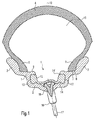
図1を参照すると、本発明に基づく実施形態における封止装置を備えたリム及び嵌合されたタイヤを断面図で示す。
The present invention will be described below with reference to the drawings.
Referring to FIG. 1, a rim with a sealing device and a fitted tire in an embodiment according to the invention are shown in cross-section.
リム1はリムベッド2及びリムフランジ3を含む。タイヤ4はその縁5,6によってリムフランジ3と接触する一方で、縁5,6の各端部に与えられた部分7によって縁座部8と接触する。
The
縁座部8は本構成では、リムフランジから内方へこぶ9まで各々延在しており、縁5,6がリムベッド2領域において、所定位置から飛び出るのを阻止する。
符号10は、リム1を実質的に鏡面対称的な半分に分割するリムの中心面を表す。
In this configuration, the edge seat portion 8 extends from the rim flange to the inward bump 9 to prevent the edges 5 and 6 from jumping out of a predetermined position in the
縁座部の面から下方に沿ったリムベッド2の領域には、封止装置12を収容するように作用するウェル11が設けられる。
図面から直接的に明らかなように、リム1はリム中心面10両側においてウェル11の領域に、図面の図1に示すようなリム1の実施形態において、こぶ9の領域からリムベッド2の領域に延出するレリーフ13を含む。
In the region of the
As is apparent directly from the drawing, the
本構成において、封止装置12はレリーフ13と形状及び寸法が実質的に相補的に構成されると共に、レリーフ13に据え付けられる。例えば軟質ゴム、密封気孔セルロース等の例えばエラストマーから作られる封止装置12は、リム中心面の両側に設けられたレリーフ13の部分と完全に入れ子状態で接触すると共に、この目的のために、レリーフ13を形成するリム1の部分の形状及び個々の表面積に従うように構成される。
In this configuration, the sealing
封止装置12は両側においてレリーフ13部分に入れ子状に収まるが、封止装置がレリーフ13に配置された時に、封止装置12のレリーフ13との完全な或いは略完全な表面接触をもたらす圧力が、封止装置12及びレリーフ13を形成する表面積に生じるように、レリーフ13に据え付けられる状態とは異なる状態で寸法が決められてもよい。
The sealing
レリーフ13は、リムベッド2と対向するその両端部において、またこぶ9と対向するその両端部において、各々くびれ14,14’を含み、結果的に、リム1、封止装置12及びチューブレスタイヤ4の間の内部空間が密封封鎖されるように、くびれ14,14’領域における封止装置12及びレリーフ13のくびれ14,14’の間に、より高い接触圧が集中させられる。
The
図面の図1から直接的に明白であるように、封止装置12は、図面の平面の右側にあるレリーフ13から、リムベッド2を越えて、図面の平面の左側にあるレリーフ13部分まで、リムベッドの全部分を、とりわけスポーク17のスポークニップル16を覆う。
As is apparent directly from FIG. 1 of the drawings, the sealing
スポークニップル16は、リム1のリムベッド2に打ち抜かれた穴18を貫通する。しかしながら、内部空間15からこの穴18を通るいかなるガス放出も、リムベッド2を完全に覆う封止装置12によって、不可能とされている。
The
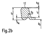
次に図2aを参照すると、図1に図示するリムの左側におけるレリーフ13部分から見たリム1の細部を示す一方、図2は、封止装置12の嵌合状態に対応するこのレリーフ領域に収容された封止装置12の細部であるが、リム1から離れた状態を示す。
Referring now to FIG. 2a, details of the
寸法l1は上端部19から下端部20までのレリーフ13の内法高さを表す。l2はくびれ14の上端部分21及びくびれ14’の下端部分22の間の内法高さを表し、リム1ではl1>l2である。
The dimension l 1 represents the inner height of the
h1は上端部19及び下端部分22の間におけるくびれ14’の高さを表す一方、h2は下端部20及び上端部分21の間におけるくびれ14の高さを表す。h1及びh2のいずれも、図示する実施形態では0よりも大きい。D1は半径方向に対向する下端部20間におけるリムの直径を表し、b1はリム1の対向する2個のくびれ14の内法断面幅を表す。
h 1 represents the height of the
次に図2bを参照すると、l3は封止装置12がレリーフ13に収容された時に、内法高さl1に対応する嵌合状態における封止装置12の内法高さを表す。この状況は、嵌合状態において内法高さh2に対応する内法高さl4、及び嵌合状態において内法高さh1に対応する内法高さh3、並びに嵌合状態において内法高さh2に対応する内法高さh4
と同様である。封止装置12がリム1に配置された時に、直径D2は直径D1に対応し、同様に封止装置12の嵌合状態において、内法幅b2は内法幅b1に対応する。
Referring now to FIG. 2b, l 3 when the sealing
It is the same. When the sealing
次に図面の図3を参照すると、非嵌合状態における封止装置12の細部を断面で示しており、内法高さl5はリム1のレリーフ13の内法高さl1よりも大きく、同様に封止装置12の内法高さl6はレリーフ13の内法高さl2よりも大きい。
Referring now to FIG. 3 of the drawings, the details of the sealing
これらの2つの状況において、封止装置12がレリーフ13の所定位置から滑り出るのを阻止するために、どれだけ乗車が困難であっても、封止装置はレリーフ13に付勢された状態で挿入される。封止装置12の非嵌合状態では、内法高さh5はリム1の内法高さh1よりも小さいので、封止装置12はレリーフに配置された時に接触力を受け取ることが同様に保証されており、状況は、封止装置12の内法高さh6がリム1の内法高さh2よりも小さいため同様である。
In these two situations, no matter how difficult the ride is to prevent the
封止装置12の非嵌合状態において、封止装置12のレリーフ13のくびれ14と対向する部分23の断面幅b3は、リム1の対応する断面幅b1よりも大きい。即ち、非嵌合状態において封止装置12の直径D3は、リム1の対応する直径D1よりも小さいので、断面幅b3が断面幅b1よりも大きいという条件を満たすことから、封止装置12の相対的な拡張に起因する封止装置12の形状変化に起因して、レリーフ13に収容されるべき封止装置12を収容する部分24が、レリーフ13の所定位置から滑り出ないことが確実にされるように、封止装置12はリム1に配置された時に半径方向に拡張する。
In a non-fitted state of the sealing
次に図面の図4を参照すると、リム1及び封止装置12が分離された状態を示す。
封止装置12をリム1に嵌合させると、封止装置12の直径が増加することになる。即ち封止装置12は、ウェル11に、ひいてはリム中心面10の両側に設けられたレリーフ13に付勢された状態で挿入される。非嵌合状態における封止装置12の断面幅b3は、リム1の断面幅b1よりも大きいので、封止装置12は実質的に、直径の増加の間に生じる封止装置12の全体幅の減少にも拘わらず、レリーフ13の領域と完全接触している。
Referring now to FIG. 4 of the drawings, the
When the sealing
図4は、平行なリム中心面10及びくびれ14,14’による封止部分によって覆われる面の間の角度として表される、即ち断面視においてくびれに形成される角度αを示す。
角度αは約−20度から約120度の範囲内の値を想定しており、即ち封止部分によって覆われる面は、リム中心面に対する20度の負の角から、リム中心面に対する約120度の角度の範囲に及ぶ。この角度αはまた、0度よりも小さい値、即ち例えば約−20度から約120度の値を想定してもよく、図8に示すように、図面の平面においてリム中心面の右側に示される被覆面Xはまた、左側に傾斜した状態で配向されてもよい。この構成は、上側封止部分14’がリム中心面10の平行線の左側にあり、それ故、封止部分14,14’を覆う面は、例えばリム中心面に対して−20度の負の角を含むように、平行線を下側封止領域14を通るように載置すると共に、この平行線を上側封止部分14’で反射させた時に実現する。
FIG. 4 shows the angle α expressed as the angle between the parallel
The angle α assumes a value in the range of about −20 degrees to about 120 degrees, i.e., the surface covered by the sealing portion is from a negative angle of 20 degrees with respect to the rim center plane to about 120 with respect to the rim center plane. Range of degrees angle. This angle α may also assume a value smaller than 0 degrees, for example a value of about −20 degrees to about 120 degrees, and is shown on the right side of the rim center plane in the plane of the drawing as shown in FIG. The coated surface X to be applied may also be oriented in a state inclined to the left side. In this configuration, the upper sealing portion 14 'is on the left side of the parallel line of the
次に図5、図6及び図7を参照すると、封止装置12の様々な実施形態の部分断面図を示しており、図面の図5に示す実施形態は、図面の図1から図4に示す実施形態に対応する一方、図面の図6に示す封止装置25の実施形態は、リムの中心面に対して実質的に横断方向に配向されたくびれ26を特徴とすることで異なる。封止装置25がレリーフ13に挿入された時に、このくびれ26によって、封止装置25は図5に示す封止装置12よりも容易に弾性圧縮することとなる。封止装置25がレリーフ13に嵌合された時にリム1のくびれ14部分を乗り越えると、封止装置25は次に弾性拡張すると共に、くびれ26はその元の形状をとる。
Referring now to FIGS. 5, 6 and 7, partial cross-sectional views of various embodiments of the sealing
次に図面の図7を参照すると、封止装置27の実施形態を示しており、封止装置27は、レリーフ13のくびれ14と対向する凹部28において、凹部28からレリーフ即ちくびれ14,14’へ半径方向外方に延出する封止縁29を各々有し、それ故間に生じる接触圧が局所的が増加する点を除き、図5に示すものと類似する。
Referring now to FIG. 7 of the drawings, an embodiment of a
本実施形態では、局所的に増加する接触圧に加えて、本発明に基づく封止装置12を特徴とするリムは、リム1と相対的に、リムの回転角速度の増加に伴い、くびれ14の領域においてより多くの接触力を受け入れる半径方向外方にある封止部分によって特徴付けられ、結果的に、封止部分のこの部分において接触圧が増加する。従って、例えばがたがた面上においてタイヤ4の牽引力を増加させるために、内部空間15内の圧力が低い時であっても、本構成は、封止装置及びレリーフ13のくびれ14領域における封止部分の間における接触圧が増加するので、たとえ高速であり、それ故リム1の回転角速度が高い時であっても、安全に内部空間15からのガス抜けを阻止する。
In this embodiment, in addition to the locally increasing contact pressure, the rim characterized by the sealing
次に図の図面の図8を参照すると、封止装置12を備えたリム1の変形実施形態を断面視で示す。図4と比較した図8から直接明らかであるように、図8に示す実施形態では、角度αは図4の実施形態における角度αよりも大きい。
Referring now to FIG. 8 of the drawing, a modified embodiment of the
レリーフ13の領域において互いに対向すると共にリム中心面10に対して角度αで傾斜するくびれ14,14’の領域の封止部分は、チューブレスタイヤ(図示なし)によって包囲された内部空間15を封止する。角度αを大きくすることにより、例えばリムの口の幅が増加させられて、より大きな断面幅を有するタイヤの嵌合を許容することができる。図8はまた、「X」で表されており、封止部分14,14’を覆うと共にリム中心面10に対して角度αで配向された面を示す。角度αに拘わらず、リム中心面10まで突出する封止装置の高さ、換言すればリムの半径方向における封止装置の高さは、レリーフの対応する高さ、即ちリム中心面へ突出するレリーフの高さよりも大きい。このため、封止装置は常に、レリーフに付勢された状態で配置される。
Sealing portions in the regions of the constricted
次に図面の図9を参照すると、本発明に基づくリムの変形実施形態を示す。再度、直接明らかであるように、本リムは、リムフランジ3及びリムベッド2を連結する領域において、リムの外側領域に平坦でない部分がないことに起因して、リムの洗浄促進に役立つ直線連結部30を含み、がたがた面を乗り越えるオフロードバイでは有利である。図1に示すリム1の高慣性回転モーメントの欠点によりこの利点を妨害するのを阻止するために、図9から明らかであるように、リムは、中空室31を組み入れた中空室断面を備えた直線連結部30に構成される。リム1の本実施形態では、深いベッド即ちリムベッド2を覆う封止装置12によって内部空間15を封止する際の前記利点があるだけでなく、高剛度、単純な面機械加工及び前述したような良好な洗浄可能性の利点もある。
Referring now to FIG. 9 of the drawings, a modified embodiment of a rim according to the present invention is shown. Again, as is apparent directly, the present rim has a linear connection that helps facilitate cleaning of the rim due to the absence of uneven portions in the outer area of the rim in the area connecting the rim flange 3 and
次に図面の図10を参照すると、本発明に基づくリム1の別の変形実施形態を示す。本リム1は、リム中心面10の両側上において、ホイールハブ(図示なし)の方向に、半径方向内方に曲がった凹部32を特徴とするリムベッド2により、実質的に図1に示すリムと異なる。またしかしながら、リムの本実施形態において、レリーフ13の部分は、図面の図1に示す実施形態と比較して、図2を参照して説明された条件l1>l2,h1>0及びh2>0が継続的に満たされている点において、僅かに変形して構成される。また、図10は更に、封止装置12において、所定位置で加硫される弁35を概略的に示す。この弁35はまた、内部空間15を膨張させるために、他の各図面に示すような封止装置に設けられてもよい。
Referring now to FIG. 10 of the drawings, another alternative embodiment of the
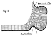
次に図面の図11を参照すると、内部空間15に存在する1バールのタイヤ圧力に対して座標で表される封止装置12に存在する圧力状態と、封止装置及びチューブレスタイヤ
を含む本発明に基づくリムが嵌合された自動二輪車の約250Km/hの算出最大速度をグラフで示す。
Referring now to FIG. 11 of the drawings, the present invention includes the pressure condition present in the
一例として作用するグラフから明らかなように、0.7N/mm2の接触圧は、前述の乗車条件の下で、くびれ14と対向する封止部分領域において、7バール(7×105Pa)の圧力比に対応して生じ、1.45N/mm2の圧力は、くびれ14’と対向する封止部分の半径方向外方部において、14.5バール(14.5×105Pa)の圧力比に対応して生じる。これにより、本発明に基づく封止装置を含むリムは、スポークリムへのチューブレスタイヤの据え付けを許容する一方、内部空間15のガス抜けを阻止して、安全な乗車条件を保証する。
As is apparent from the graph acting as an example, a contact pressure of 0.7 N / mm 2 is 7 bar (7 × 10 5 Pa) in the sealed part region facing the
封止装置の変形版では、内方にある封止部分部及び外方にある封止部分部において、圧力状態が車両の静止時と実質的に同じであるように構成することも可能であり、結果的に、封止部分領域に存在する圧力は、1バール(1×10⁵Pa)よりも大きくなる。スポークホイールが回転している時の外方封止部分領域における遠心力に起因して、内方封止部分領域よりも高い圧力が実現するので、封止装置の質量分散は、スポークホイールの回転時に、内方封止部分領域とおおよそ同じ圧力条件が、外方封止部分領域に存在するように、別の変形物に基づいて変化させられてもよい。 In the modified version of the sealing device, it is also possible to configure the pressure state in the inner sealing portion and the outer sealing portion to be substantially the same as when the vehicle is stationary. As a result, the pressure present in the sealed part region is greater than 1 bar (1 × 10 5 Pa). Due to the centrifugal force in the outer sealing part area when the spoke wheel is rotating, a higher pressure is achieved than in the inner sealing part area, so the mass dispersion of the sealing device is the rotation of the spoke wheel At times, approximately the same pressure conditions as the inner sealed partial region may be varied based on other variations such that they exist in the outer sealed partial region.
次に図12を参照すると、本発明に基づくリム1の更に別の変形実施形態を示す。直接的に明白であるように、本リム1は、レリーフ13において、リムの中心面10に対して角度αで傾斜する封止部分を含むと共に、リムベッド2及びリムフランジ3を連結する部分に中空室31を有しており、中空室31は同様に、回転移動させられる質量を減少させるように作用する。図12からまた明らかであるように、リムベッド2及びリムフランジ3を連結する部分は、連続湾曲を備えるように構成され、即ち連結部は途切れがない連続的な輪郭を有する。
Referring now to FIG. 12, yet another alternative embodiment of the
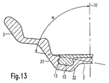
次に図13を参照すると、リム1のレリーフ13領域に配置された封止部分及びリム中心面10の間に一層大きな角度αを特徴とするリム1の更に別の変形実施形態を示す。図面の図10に示す実施形態と同様に、本実施形態は、リムベッド2及びリムフランジ3を連結する階段状連続部33を備えた凹部32を含む。
Referring now to FIG. 13, there is shown yet another alternative embodiment of the
次に図面の図14を参照すると、本発明に基づく封止装置12を特徴とするリム1の更なる変形実施形態を示す。直接的に明白であるように、リム1は図14に示すように、リムベッド2及び中空室31が含まれるリムフランジ3を連結する直線領域を有する。くびれ14及び14’の領域に配置される封止部分は、本実施形態において、上記に定義される角度αが約0度の値をとるように、リム中心面10と実質的に平行に配向される面を覆う。
Referring now to FIG. 14 of the drawings, a further alternative embodiment of the
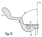
次に図面の図15を参照すると、本発明に基づく封止装置12を備えたリム1の変形実施形態を示す。本実施形態において、角度αは約70度の角度をとると共に、リム1は図面の図10に示す実施形態のものと同様な凹部32を特徴とする。
Referring now to FIG. 15 of the drawings, a modified embodiment of the
次に図面の図16及び図17を参照すると、本発明に基づく封止装置12を備えたリム1の変形実施形態を示す。図16に示すリム1の実施形態では、凹部32及びリムフランジ3を連結する連結部33は、最初に内方に曲げられており、続いて連結部34領域では直線状に延在する一方、図17に示すリム1の連結部33は、リム中心面10に対して約15度の角度で増加し、続いてリム中心面10に対して略横向きに配向される連結部34に変形する。
16 and 17 of the drawings, there is shown a modified embodiment of the
次に図面の図18を参照すると、封止装置36の更なる実施形態の断面図を示す。直接的に明白であるように、既に説明した封止装置12,25及び27と類似する本封止装置36は、リムのレリーフ13において嵌合するように設けられた横羽根37を含む。また封止装置の羽根37には、封止装置36が大きな力を要することなく、リム1のレリーフ13に挿入され得るように、矢印P(図23)の方向に弾性的に圧縮するのを容易にするように作用するくびれ38が設けられる。
Referring now to FIG. 18 of the drawings, a cross-sectional view of a further embodiment of the sealing
図18に示す封止装置36の実施形態では、2個の羽根37の間の中間部39は、上述した封止装置とは異なって構成される。直接的に明白であるように、中間部39は2個の層40,41に分割されており、間に間隙42を備える。2個の層40,41は、例えばスポークニップル又はスポークの鋭角端に起因して下層40に生じる破損が、クラックの形態をなして、上層41に伝播しないことを保証する。すなわち、たとえこのようなクラックが下層40に生じるとしても、上層41は破損することなく、内部空間15のガス抜けが生じないように、クラックは2個の層40,41の間の間隙42を乗り越えることができない。
In the embodiment of the sealing
また図18から明白であるように、封止装置36は中間部39において、湾曲形状43を特徴としており、湾曲形状43は、封止装置36がリムの容易な嵌合のために、両矢印Fの方向に合わせて単純に押し込められ得るように直線輪郭から離脱し、封止装置36は、予め定められたようにリム1内に位置する。湾曲形状43に代えて、例えば楕円の一部の形状、或いは切妻形状等の他の形状であっても、封止装置36の両矢印Fの方向への柔軟な押し込みを許容する限り可能である。本態様はまた、図4と共に説明したものと同様な効果をもたらし、即ちレリーフ13に収容された羽根37は、湾曲形状がリムの幅方向においてばねのように作用し、従って羽根がレリーフに付勢されているので、レリーフの所定位置から滑り出ることはできない。
As is also apparent from FIG. 18, the sealing
次に図面の図19を参照すると、封止装置44の更なる実施形態の断面視を示す。これは、下層40及び上層41の間の中間部39において、間隙42を維持する際に、下層40を上層41と連結させるウェブ45が2個の層40,41と一体的に設けられた点において、図18に示す封止装置36と実質的に異なる。中間部39における封止装置44の2層構造の利点を維持する際に、本構成は、2個の層40,41が、封止装置44の組み付けの間に互いに離間させられており、また例えば合わせて固着されないことを保証しており、またこれは、スポークニップル又はスポーク端に起因して下層40に生じる可能性がある封止装置44の破損が、ウェブ45を介して上層41まで伝播するのを阻止することを示している。
Referring now to FIG. 19 of the drawings, a cross-sectional view of a further embodiment of the sealing
次に図20を参照すると、上記と同じ効果を有するが、ウェブ45に代えて、1個の層のみ、即ち一体的に構成された層40を有し、間隙42を維持する際に、2個の層40,41が固着しないことを保証する突起47が設けられる点において実質的に図19に示す封止装置44と異なる封止装置46が示されている。加えて、下層40のいかなる破損も、クラックとして、突起47を介して上層41に伝播しないことも示されている。
Referring now to FIG. 20, it has the same effect as described above, but instead of the
次に図面の図21を参照すると、下層40及び上層41の間に、例えばエラストマーを含む封止装置48の材料以外の材料から作られ、2個の層40,41が固着するのを阻止する一方、下層40の破損がクラックとして上層41へ伝播しないのを保証するインレイ49が設けられる点において、図18から図20に示す封止装置と異なる封止装置48の更なる実施形態が断面視で示されている。
Referring now to FIG. 21 of the drawings, between the
次に図面の図22を参照すると、2個のレリーフ13を連結する連結部50において、くびれ14の下端部20の直径D1よりも小さい直径D4を有する図22に示すリム1に
よって、例えば図面の図1に示すリム1と実質的に異なる、本発明に基づくリム1の更なる実施形態の断面視が示されている。この直径の相違は、中間部39の多層構造に起因する封止装置36,44,46,48の付加的な高さ「b」を埋め合わせる間隙「b」(図18から図21を参照)を結果的にもたらす。
Referring now to FIG. 22 of the drawings, the
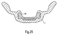
図23,図24及び図25は、最後に、図22に示すように、封止装置36をリム1に嵌合する際に必要な個々の工程の順序を示す。封止装置36のみが図23、図24及び図25に示されているが、封止装置12,25,27,44,46,48の別の実施形態も、同様な方法で、リム1に嵌合され得る。
FIG. 23, FIG. 24 and FIG. 25 finally show the order of the individual steps required when fitting the sealing
次に図23を参照すると、封止装置36のリム1への嵌合順序の第1工程が示されている。封止装置36は、封止装置36の幅が2個のくびれ14’によって形成された間隙を通過するために減少させられるように、矢印F(図18)の方向に押し込められる。この位置において、封止装置36は未だ、その対向部23によって、レリーフ13の下側くびれ14と接触していない。次に力が封止装置へ更に、矢印P(図23)の方向へ付与された時には、部分23が既にくびれ14と接触しており、封止装置36の中間部39が既にリムベッド2に載っている図24に示す据え付け位置をなす。矢印F(図18)の方向への更なる力の付与は、封止装置36の2個の羽根37を、各レリーフ13まで摺動させ、従ってリム1に嵌合された封止装置36の最終位置が達成される。
Referring now to FIG. 23, the first step in the fitting sequence of the sealing
次に、このように完了されたリム1へのタイヤ4の簡単な据え付けは、ホイールの据え付けを完了させる。
封止装置及びリムは、図23、図24及び図25に示すように、チューブレスタイヤを据え付けるために、封止装置が嵌合された完全組み立てスポークホイールリムを形成するべく、互いに独立して組み立てられ、且つ単純に合わせて組み付けられてもよい。
Next, the simple installation of the tire 4 on the
The sealing device and rim are assembled independently of each other to form a fully assembled spoke wheel rim fitted with the sealing device to install a tubeless tire, as shown in FIGS. And may be assembled together simply.
上記全てから、本発明は、チューブレスタイヤを備えたスポークホイールを形成するために、封止装置を備えたリムを提供する。本発明はまた、チューブレスタイヤ及び本発明に基づくリムと共に使用することを目的とする封止装置を備えたスポークホイールを形成するために、封止装置用リムを提供する。従って本発明は、スポークホイールを備えたチューブの使用を除去することを可能にすると共に、一般的なチューブレスタイヤをスポークリムに嵌合させるのを許容する。回転質量の低減に起因して、封止装置と共に示されるリムは、嵌合された車両、例えば自動二輪車又は自転車の操縦機敏性を著しく向上させる。封止装置を備えたリムは、例えばオフロードスポーツイベントで、またロードレース又は他の利用分野において使用される周知のリムよりも強い。チューブレスタイヤの嵌合は、チューブのガス抜けからのタイヤのパンクが今や除去されるので、安全性において巨大な利益をもたらす。チューブタイヤにおいてしばしば観察されるような、チューブに加硫される弁の剪断は、チューブの必要性を取り除くことにより、完全に回避される。本発明に基づく封止装置を備えたリムは、例えばがたがた面上でチューブレスタイヤによって達成される牽引力が著しく増加させられるように、低い膨張圧でチューブレスタイヤを軽量スポークリムに搭載することを許容する。封止装置を備えたリムの高い回転角速度、また結果的に嵌合された例えば自動二輪車の高い速度であっても、スポーク及び封止装置、並びにチューブレスタイヤの内部空間のガス抜けは、安全に回避される。 In all, the present invention provides a rim with a sealing device to form a spoke wheel with a tubeless tire. The present invention also provides a rim for a sealing device for forming a spoke wheel with a sealing device intended for use with a tubeless tire and a rim according to the present invention. The present invention thus makes it possible to eliminate the use of tubes with spoke wheels and to allow a general tubeless tire to fit into the spoke rim. Due to the reduced rotational mass, the rim shown with the sealing device significantly improves the steering agility of a fitted vehicle, such as a motorcycle or bicycle. Rims with sealing devices are stronger than well-known rims used, for example, in off-road sporting events and in road racing or other applications. The fitting of a tubeless tire provides a huge safety benefit as the tire puncture from the outgassing of the tube is now eliminated. The shearing of valves vulcanized into tubes, as often observed in tube tires, is completely avoided by eliminating the need for tubes. A rim with a sealing device according to the present invention allows a tubeless tire to be mounted on a lightweight spoke rim with low inflation pressure so that, for example, the traction force achieved by the tubeless tire on the back surface is significantly increased. . Even at high rotational angular velocities of the rim with the sealing device and the high speed of the resulting fitted motorcycle, for example, the spokes and sealing device and the outgassing of the inner space of the tubeless tire are safe. Avoided.
詳細に説明されていない個々の特徴に関しては、請求の範囲及び図面において別に言及される。 Individual features not described in detail are referred to separately in the claims and drawings.
1…リム、2…リムベッド、3…リムフランジ、4…タイヤ、5…縁、6…縁、7…端部、8…縁座部、9…こぶ、10…リム中心面、11…ウェル、12…封止装置、13…レリーフ、14…くびれ、封止部分、14’…くびれ、封止部分、15…内部空間、16…スポークニップル、17…スポーク、18…打ち抜き穴、19…上端部、20…下端部、21…上端部分、22…下端部分、23…対向部、24…収納部、25…封止装置、26…くびれ、27…封止装置、28…凹部、29…封止縁、30…連結部、31…中空室、32…凹部、33…連結部、34…連結部、35…弁、36…封止装置、37…羽根、38…くびれ、39…中間部、40…層、41…層、42…間隙、43…湾曲形状、44…封止装置、45…ウェブ、45…封止装置、47…突起、48…封止装置、49…インレイ、50…連結部、F…両矢印、P…矢印。
DESCRIPTION OF
Claims (47)
)部分で、該レリーフ(13)のくびれ(14,14’)の断面幅(b1)よりも大きいことを特徴とする請求項1乃至9のいずれか一項に記載のリム。 The cross-sectional width (b 3 ) of the sealing device (12, 25, 27, 36, 44, 46, 48) is the relief (13) assigned to the constriction (14, 14 ′) in the non-fitted state.
The rim according to claim 1, wherein the rim is larger than the cross-sectional width (b 1 ) of the constriction (14, 14 ′) of the relief (13).
隙(42)を維持する少なくとも1個のウェブ(45)が、該層と一体的に設けられることを特徴とする請求項42又は43に記載の封止装置。 Between the layers (0, 41), at least one web (45) is provided integrally with the layers, maintaining the gap (42) while connecting the layers (40, 41) to segments. 44. The sealing device according to claim 42 or 43.
Applications Claiming Priority (2)
| Application Number | Priority Date | Filing Date | Title |
|---|---|---|---|
| DE102004055892A DE102004055892B4 (en) | 2004-11-19 | 2004-11-19 | Spoked wheel rim for tubeless tires |
| PCT/EP2005/012295 WO2006053736A2 (en) | 2004-11-19 | 2005-11-16 | Spoke wheel rim for tubeless tyres |
Publications (2)
| Publication Number | Publication Date |
|---|---|
| JP2008520487A true JP2008520487A (en) | 2008-06-19 |
| JP2008520487A5 JP2008520487A5 (en) | 2009-01-22 |
Family
ID=36149051
Family Applications (1)
| Application Number | Title | Priority Date | Filing Date |
|---|---|---|---|
| JP2007541782A Pending JP2008520487A (en) | 2004-11-19 | 2005-11-16 | Spoke wheel rim for tubeless tires |
Country Status (7)
| Country | Link |
|---|---|
| US (1) | US7487811B2 (en) |
| EP (1) | EP1812246B1 (en) |
| JP (1) | JP2008520487A (en) |
| AT (1) | ATE494159T1 (en) |
| DE (2) | DE102004055892B4 (en) |
| ES (1) | ES2359323T3 (en) |
| WO (1) | WO2006053736A2 (en) |
Cited By (2)
| Publication number | Priority date | Publication date | Assignee | Title |
|---|---|---|---|---|
| JP2012515115A (en) * | 2009-01-14 | 2012-07-05 | ジャネッティ・ルオーテ・ソシエタ・ペル・アチオニ | Tubeless spoke wheels for vehicles, especially motorcycles |
| JP2021054113A (en) * | 2019-09-27 | 2021-04-08 | 本田技研工業株式会社 | Tubeless wire spoke wheel and rim |
Families Citing this family (30)
| Publication number | Priority date | Publication date | Assignee | Title |
|---|---|---|---|---|
| EP1418064B1 (en) | 2002-11-08 | 2008-03-26 | Campagnolo Srl | Method for manufacturing a spoked wheel for bicycles |
| ES2305430T3 (en) * | 2003-06-26 | 2008-11-01 | Campagnolo S.R.L. | ALLLED RIM FOR A BICYCLE WHEEL AND MANUFACTURING PROCEDURE OF SUCH RIM. |
| DE60322051D1 (en) | 2003-08-11 | 2008-08-21 | Campagnolo Srl | Bicycle rim made of composite material and method for its production |
| US7431404B2 (en) * | 2005-08-05 | 2008-10-07 | Shimano Inc. | Bicycle having annular sealing member |
| DE102006039686A1 (en) * | 2006-08-24 | 2008-02-28 | Bayerische Motoren Werke Ag | Tubeless spoked wheel for two-wheelers, especially for motorcycles |
| ITMI20072232A1 (en) | 2007-11-26 | 2009-05-27 | Campagnolo Srl | RIM FOR BICYCLE WHEEL AND BICYCLE WHEEL INCLUDING SUCH RIM |
| ITMI20072231A1 (en) | 2007-11-26 | 2009-05-27 | Campagnolo Srl | RIM FOR BICYCLE WHEEL AND BICYCLE WHEEL INCLUDING SUCH RIM |
| ATE509779T1 (en) | 2008-03-14 | 2011-06-15 | Campagnolo Srl | WHEEL RIM MADE OF COMPOSITE MATERIAL FOR A TUBELESS BICYCLE WHEEL AND A TUBELESS BICYCLE EQUIPPED WITH SUCH A WHEEL RIM |
| DE102008058812A1 (en) | 2008-11-24 | 2010-05-27 | Behr Industry Reichenbach Gmbh | Rim for a spoked wheel |
| US8757231B2 (en) * | 2009-01-26 | 2014-06-24 | E. I. Du Pont De Nemours And Company | Elastomer tire sealing ring |
| US20120062021A1 (en) * | 2009-05-30 | 2012-03-15 | Reynolds Cycling Llc | Wheel Lip |
| US20110084543A1 (en) * | 2009-05-30 | 2011-04-14 | Reynolds Cycling Llc | Bead Seat Clincher |
| JP5001986B2 (en) * | 2009-09-08 | 2012-08-15 | 本田技研工業株式会社 | Vehicle wheel |
| NL2004125C2 (en) * | 2010-01-21 | 2011-07-25 | 3T Design Ltd | A bicycle wheel rim having sidewardly opening two-part slit shaped spoke mounting apertures. |
| US9067465B2 (en) * | 2010-02-25 | 2015-06-30 | Harley-Davidson Motor Company Group, LLC | Tubeless rim seal for a laced wheel |
| DE102011015218A1 (en) | 2011-03-25 | 2012-09-27 | Harald Schmid | Vehicle wheel, rim and vehicle |
| US8978725B2 (en) * | 2011-10-20 | 2015-03-17 | Shimano Inc. | Bicycle wheel rim structure |
| CN102950967A (en) * | 2012-02-10 | 2013-03-06 | 上海康适达轮圈有限公司 | Tubeless rim |
| TWI468307B (en) * | 2013-02-08 | 2015-01-11 | 拓肯興業股份有限公司 | Reinforcing structure and composite wheel rim comprising the same |
| DE102014200541A1 (en) | 2014-01-14 | 2015-07-16 | Iam Components Gmbh | Speichenradfelge |
| DE102014200542A1 (en) | 2014-01-14 | 2015-07-16 | Iam Components Gmbh | Speichenradfelge |
| US10773545B2 (en) * | 2014-01-15 | 2020-09-15 | ThyssenKrupp Carbon Components GmbH | Vehicle wheel having a connection of a wheel rim with rim base made from fiber composite material and a wheel disc |
| US9481202B2 (en) * | 2014-01-31 | 2016-11-01 | Specialized Bicycle Components, Inc. | Plug for a tubeless bicycle wheel |
| US10596850B2 (en) * | 2015-12-07 | 2020-03-24 | Enve Composites, Llc | Rim strip for bicycle rim |
| US10052911B2 (en) * | 2015-12-07 | 2018-08-21 | Enve Composites, Llc | Rim strip for bicycle rim |
| ITUB20159149A1 (en) * | 2015-12-15 | 2017-06-15 | Star Bianchi Srl | BIFUNCTIONAL DEVICE FOR PROTECTING THE AIR CHAMBER OF A VEHICLE WHEEL OR TO ALLOW THE WHEEL TO OPERATE WITHOUT AIRCRAFT, PROCEDURE AND EQUIPMENT TO MANUFACTURE THE DEVICE AND VEHICLE WHEEL INCLUDING THE DEVICE ITSELF |
| EP3228473A1 (en) * | 2016-04-04 | 2017-10-11 | Mubea Carbo Tech GmbH | Wheel for a vehicle |
| US10710401B2 (en) * | 2017-12-07 | 2020-07-14 | Ford Global Technologies, Llc | Wheel apparatus for use with vehicles |
| US20200122502A1 (en) * | 2018-10-17 | 2020-04-23 | Sram, Llc | Spoke cover for a bicycle rim |
| CN112590455A (en) * | 2020-12-28 | 2021-04-02 | 鼎镁(昆山)新材料科技有限公司 | Rim of tubeless wheel and bicycle |
Citations (6)
| Publication number | Priority date | Publication date | Assignee | Title |
|---|---|---|---|---|
| JPS4864904U (en) * | 1971-11-25 | 1973-08-17 | ||
| JPS6154302A (en) * | 1984-08-27 | 1986-03-18 | Yamaha Motor Co Ltd | Spoke wheel for tubeless tire |
| EP0616911A2 (en) * | 1993-03-26 | 1994-09-28 | Jorge Nadal Aloy | Arrangement for inflating tubeless wheels |
| JPH07112601A (en) * | 1993-03-15 | 1995-05-02 | Jorge N Aloy | Sealing device for tubeless radial spoked wheel |
| JPH10250309A (en) * | 1997-03-17 | 1998-09-22 | R Thomasberg Paul | Tubeless tire and rim for bicycle |
| US20040095014A1 (en) * | 2002-11-20 | 2004-05-20 | Mavic S.A. | Base for a rim of a wheel and a rim having such a base |
Family Cites Families (10)
| Publication number | Priority date | Publication date | Assignee | Title |
|---|---|---|---|---|
| DE1002210B (en) * | 1955-03-26 | 1957-02-07 | Manfred Juengling | Insert for tubeless tires |
| US3008770A (en) * | 1956-12-19 | 1961-11-14 | American Mach & Foundry | Rim for tubeless bicycle tires |
| BE662654A (en) * | 1964-04-18 | |||
| GB1450506A (en) * | 1973-09-25 | 1976-09-22 | Sumitomo Rubber Ind | Vehicle wheel structure |
| FR2622149B1 (en) * | 1987-10-26 | 1991-01-25 | Michelin & Cie | RIM FOR TIRE COMPRISING A ROD THAT ALLOWS TO ROLL IN A DEFLATED CONDITION |
| US4824177A (en) * | 1987-10-29 | 1989-04-25 | Aloy Jorge N | Spoked vehicle wheel with tubeless tire |
| JP3605439B2 (en) * | 1995-06-15 | 2004-12-22 | 本田技研工業株式会社 | Air seal device for spoke wheels for tubeless tires |
| DE29803256U1 (en) * | 1998-02-25 | 1998-06-04 | Heger Heinz | Safety rim for bicycles and similar vehicles |
| IT245313Y1 (en) * | 1998-06-05 | 2002-03-20 | Aprilia World Service B V | PERFECTED SPOKE WHEEL |
| US6782931B2 (en) * | 2002-01-22 | 2004-08-31 | Stanley Koziatek | Tubeless tire compound and a system and method for retrofitting non-tubeless tires |
-
2004
- 2004-11-19 DE DE102004055892A patent/DE102004055892B4/en active Active
-
2005
- 2005-11-16 JP JP2007541782A patent/JP2008520487A/en active Pending
- 2005-11-16 US US11/281,723 patent/US7487811B2/en active Active
- 2005-11-16 DE DE502005010813T patent/DE502005010813D1/en active Active
- 2005-11-16 WO PCT/EP2005/012295 patent/WO2006053736A2/en active Application Filing
- 2005-11-16 AT AT05820557T patent/ATE494159T1/en active
- 2005-11-16 ES ES05820557T patent/ES2359323T3/en active Active
- 2005-11-16 EP EP05820557A patent/EP1812246B1/en active Active
Patent Citations (6)
| Publication number | Priority date | Publication date | Assignee | Title |
|---|---|---|---|---|
| JPS4864904U (en) * | 1971-11-25 | 1973-08-17 | ||
| JPS6154302A (en) * | 1984-08-27 | 1986-03-18 | Yamaha Motor Co Ltd | Spoke wheel for tubeless tire |
| JPH07112601A (en) * | 1993-03-15 | 1995-05-02 | Jorge N Aloy | Sealing device for tubeless radial spoked wheel |
| EP0616911A2 (en) * | 1993-03-26 | 1994-09-28 | Jorge Nadal Aloy | Arrangement for inflating tubeless wheels |
| JPH10250309A (en) * | 1997-03-17 | 1998-09-22 | R Thomasberg Paul | Tubeless tire and rim for bicycle |
| US20040095014A1 (en) * | 2002-11-20 | 2004-05-20 | Mavic S.A. | Base for a rim of a wheel and a rim having such a base |
Cited By (3)
| Publication number | Priority date | Publication date | Assignee | Title |
|---|---|---|---|---|
| JP2012515115A (en) * | 2009-01-14 | 2012-07-05 | ジャネッティ・ルオーテ・ソシエタ・ペル・アチオニ | Tubeless spoke wheels for vehicles, especially motorcycles |
| JP2021054113A (en) * | 2019-09-27 | 2021-04-08 | 本田技研工業株式会社 | Tubeless wire spoke wheel and rim |
| JP7121716B2 (en) | 2019-09-27 | 2022-08-18 | 本田技研工業株式会社 | Tubeless wire spoke wheels and rims |
Also Published As
| Publication number | Publication date |
|---|---|
| US20060108041A1 (en) | 2006-05-25 |
| EP1812246B1 (en) | 2011-01-05 |
| ATE494159T1 (en) | 2011-01-15 |
| US7487811B2 (en) | 2009-02-10 |
| DE102004055892B4 (en) | 2010-12-09 |
| ES2359323T3 (en) | 2011-05-20 |
| DE502005010813D1 (en) | 2011-02-17 |
| WO2006053736A2 (en) | 2006-05-26 |
| EP1812246A2 (en) | 2007-08-01 |
| DE102004055892A1 (en) | 2006-05-24 |
| WO2006053736A3 (en) | 2006-11-09 |
Similar Documents
| Publication | Publication Date | Title |
|---|---|---|
| JP2008520487A (en) | Spoke wheel rim for tubeless tires | |
| US3965957A (en) | Vehicle wheel structure | |
| US4163466A (en) | Tubeless tire, safety support and rim assembly | |
| JPH0217363B2 (en) | ||
| TW201144098A (en) | Vehicle wheel assemblies and valves for use with a central tire inflation system | |
| WO2017193547A1 (en) | Emergency safety device for automobile tire blowout | |
| TW201924959A (en) | Road tubeless bicycle wheel | |
| RU2380238C2 (en) | Device to support tire in blowing off and tire assembled with such device | |
| JPS62227801A (en) | Wheel for motorcycle | |
| US6976517B2 (en) | Cycle rim and tubeless mounted assembly for a cycle | |
| US5273093A (en) | Racing tire assembly | |
| US20060096687A1 (en) | Tubeless pneumatic tire, and method of making same | |
| JP4015286B2 (en) | Pneumatic tire | |
| AU2015259643A1 (en) | Foam tire flap for low pressure applications | |
| JP2011521847A (en) | Inner tube and manufacturing method thereof | |
| US6892777B2 (en) | Rim with seats inclined outwards and assemblies comprising such a rim and an inflated bearing support | |
| JP2007106259A (en) | Rim | |
| JPS5813361B2 (en) | Kuuki Tire Shearin | |
| WO2009078110A1 (en) | Tire wheel of double structure and method of mounting same | |
| CN109203861A (en) | Wheel tyre | |
| US20040177910A1 (en) | Bicycle wheel with inner and outer tire members | |
| JP4324659B2 (en) | Seal structure of B type lateral loading wheel | |
| JPS60146705A (en) | Wheel for car | |
| JP2005532945A (en) | Tubeless mounting assembly for bicycles, rims and tubeless tires | |
| US1891336A (en) | Wheel |
Legal Events
| Date | Code | Title | Description |
|---|---|---|---|
| A521 | Request for written amendment filed |
Free format text: JAPANESE INTERMEDIATE CODE: A523 Effective date: 20081117 |
|
| A621 | Written request for application examination |
Free format text: JAPANESE INTERMEDIATE CODE: A621 Effective date: 20081117 |
|
| A131 | Notification of reasons for refusal |
Free format text: JAPANESE INTERMEDIATE CODE: A131 Effective date: 20110426 |
|
| A601 | Written request for extension of time |
Free format text: JAPANESE INTERMEDIATE CODE: A601 Effective date: 20110715 |
|
| RD02 | Notification of acceptance of power of attorney |
Free format text: JAPANESE INTERMEDIATE CODE: A7422 Effective date: 20110801 |
|
| RD04 | Notification of resignation of power of attorney |
Free format text: JAPANESE INTERMEDIATE CODE: A7424 Effective date: 20110805 |
|
| A521 | Request for written amendment filed |
Free format text: JAPANESE INTERMEDIATE CODE: A821 Effective date: 20110802 |
|
| A601 | Written request for extension of time |
Free format text: JAPANESE INTERMEDIATE CODE: A601 Effective date: 20110826 |
|
| A602 | Written permission of extension of time |
Free format text: JAPANESE INTERMEDIATE CODE: A602 Effective date: 20110902 |
|
| A521 | Request for written amendment filed |
Free format text: JAPANESE INTERMEDIATE CODE: A523 Effective date: 20110912 |
|
| A131 | Notification of reasons for refusal |
Free format text: JAPANESE INTERMEDIATE CODE: A131 Effective date: 20120207 |
|
| A02 | Decision of refusal |
Free format text: JAPANESE INTERMEDIATE CODE: A02 Effective date: 20120710 |