JP2008520425A - Liquid supply and filter assembly for spray gun - Google Patents
Liquid supply and filter assembly for spray gun Download PDFInfo
- Publication number
- JP2008520425A JP2008520425A JP2007543051A JP2007543051A JP2008520425A JP 2008520425 A JP2008520425 A JP 2008520425A JP 2007543051 A JP2007543051 A JP 2007543051A JP 2007543051 A JP2007543051 A JP 2007543051A JP 2008520425 A JP2008520425 A JP 2008520425A
- Authority
- JP
- Japan
- Prior art keywords
- filter
- lid
- filter mesh
- assembly
- mesh
- Prior art date
- Legal status (The legal status is an assumption and is not a legal conclusion. Google has not performed a legal analysis and makes no representation as to the accuracy of the status listed.)
- Withdrawn
Links
- 239000007788 liquid Substances 0.000 title claims abstract description 129
- 239000007921 spray Substances 0.000 title abstract description 10
- 239000000463 material Substances 0.000 claims description 17
- -1 polypropylene part Polymers 0.000 claims description 16
- 238000002347 injection Methods 0.000 claims description 15
- 239000007924 injection Substances 0.000 claims description 15
- 239000004744 fabric Substances 0.000 claims description 13
- 229920001778 nylon Polymers 0.000 claims description 13
- 239000004677 Nylon Substances 0.000 claims description 11
- 230000002093 peripheral effect Effects 0.000 claims description 11
- 230000005484 gravity Effects 0.000 claims description 8
- 230000001681 protective effect Effects 0.000 claims description 5
- 239000000758 substrate Substances 0.000 abstract description 2
- 238000000034 method Methods 0.000 description 21
- 238000003466 welding Methods 0.000 description 15
- 239000004743 Polypropylene Substances 0.000 description 11
- 229920001155 polypropylene Polymers 0.000 description 11
- 230000000712 assembly Effects 0.000 description 7
- 238000000429 assembly Methods 0.000 description 7
- 239000012530 fluid Substances 0.000 description 5
- 238000000465 moulding Methods 0.000 description 5
- 239000003973 paint Substances 0.000 description 5
- 229920000642 polymer Polymers 0.000 description 5
- 238000004519 manufacturing process Methods 0.000 description 4
- 238000002844 melting Methods 0.000 description 4
- 230000008018 melting Effects 0.000 description 4
- 230000008569 process Effects 0.000 description 4
- 239000002344 surface layer Substances 0.000 description 4
- 239000004698 Polyethylene Substances 0.000 description 3
- 238000001914 filtration Methods 0.000 description 3
- 238000001746 injection moulding Methods 0.000 description 3
- 229920000573 polyethylene Polymers 0.000 description 3
- 238000004026 adhesive bonding Methods 0.000 description 2
- 230000006870 function Effects 0.000 description 2
- 239000000155 melt Substances 0.000 description 2
- 239000007769 metal material Substances 0.000 description 2
- 238000012986 modification Methods 0.000 description 2
- 230000004048 modification Effects 0.000 description 2
- 239000002991 molded plastic Substances 0.000 description 2
- 239000004033 plastic Substances 0.000 description 2
- 229920003023 plastic Polymers 0.000 description 2
- 239000002861 polymer material Substances 0.000 description 2
- 238000007789 sealing Methods 0.000 description 2
- 229910052782 aluminium Inorganic materials 0.000 description 1
- XAGFODPZIPBFFR-UHFFFAOYSA-N aluminium Chemical compound [Al] XAGFODPZIPBFFR-UHFFFAOYSA-N 0.000 description 1
- 230000004888 barrier function Effects 0.000 description 1
- 239000003054 catalyst Substances 0.000 description 1
- 238000005553 drilling Methods 0.000 description 1
- 239000003365 glass fiber Substances 0.000 description 1
- 238000007373 indentation Methods 0.000 description 1
- 238000005304 joining Methods 0.000 description 1
- 229920001684 low density polyethylene Polymers 0.000 description 1
- 239000004702 low-density polyethylene Substances 0.000 description 1
- 230000014759 maintenance of location Effects 0.000 description 1
- 229910052751 metal Inorganic materials 0.000 description 1
- 239000002184 metal Substances 0.000 description 1
- 238000002156 mixing Methods 0.000 description 1
- 239000000203 mixture Substances 0.000 description 1
- 229920000728 polyester Polymers 0.000 description 1
- 238000005507 spraying Methods 0.000 description 1
- 229910001220 stainless steel Inorganic materials 0.000 description 1
- 239000010935 stainless steel Substances 0.000 description 1
- 238000003856 thermoforming Methods 0.000 description 1
Images


Classifications
-
- B—PERFORMING OPERATIONS; TRANSPORTING
- B05—SPRAYING OR ATOMISING IN GENERAL; APPLYING FLUENT MATERIALS TO SURFACES, IN GENERAL
- B05B—SPRAYING APPARATUS; ATOMISING APPARATUS; NOZZLES
- B05B7/00—Spraying apparatus for discharge of liquids or other fluent materials from two or more sources, e.g. of liquid and air, of powder and gas
- B05B7/24—Spraying apparatus for discharge of liquids or other fluent materials from two or more sources, e.g. of liquid and air, of powder and gas with means, e.g. a container, for supplying liquid or other fluent material to a discharge device
- B05B7/2402—Apparatus to be carried on or by a person, e.g. by hand; Apparatus comprising containers fixed to the discharge device
- B05B7/2478—Gun with a container which, in normal use, is located above the gun
-
- B—PERFORMING OPERATIONS; TRANSPORTING
- B05—SPRAYING OR ATOMISING IN GENERAL; APPLYING FLUENT MATERIALS TO SURFACES, IN GENERAL
- B05B—SPRAYING APPARATUS; ATOMISING APPARATUS; NOZZLES
- B05B7/00—Spraying apparatus for discharge of liquids or other fluent materials from two or more sources, e.g. of liquid and air, of powder and gas
- B05B7/24—Spraying apparatus for discharge of liquids or other fluent materials from two or more sources, e.g. of liquid and air, of powder and gas with means, e.g. a container, for supplying liquid or other fluent material to a discharge device
- B05B7/2402—Apparatus to be carried on or by a person, e.g. by hand; Apparatus comprising containers fixed to the discharge device
- B05B7/2405—Apparatus to be carried on or by a person, e.g. by hand; Apparatus comprising containers fixed to the discharge device using an atomising fluid as carrying fluid for feeding, e.g. by suction or pressure, a carried liquid from the container to the nozzle
- B05B7/2408—Apparatus to be carried on or by a person, e.g. by hand; Apparatus comprising containers fixed to the discharge device using an atomising fluid as carrying fluid for feeding, e.g. by suction or pressure, a carried liquid from the container to the nozzle characterised by the container or its attachment means to the spray apparatus
Landscapes
- Containers And Packaging Bodies Having A Special Means To Remove Contents (AREA)
- Nozzles (AREA)
- Filtration Of Liquid (AREA)
Abstract
液体供給体とフィルターとの組立体を開示する。液体供給体とフィルターとの組立体は、液体を基体に付与するための噴射装置またはスプレーガンと併用することができる。 An assembly of a liquid supply and a filter is disclosed. The liquid supply and filter assembly can be used in combination with a spray device or spray gun for applying liquid to the substrate.
Description
本発明は、液体供給体とフィルターとの部材および組立体に関する。液体供給体とフィルターとの部材および組立体は、重力供給される液体(たとえば塗料)噴射装置またはスプレーガン中に使用すると特に好適である。 The present invention relates to a member and an assembly of a liquid supply body and a filter. The liquid supply and filter members and assemblies are particularly suitable for use in gravity-fed liquid (eg paint) sprayers or spray guns.
1998年7月30日に公開された国際公開第98/32539号パンフレット、米国特許第6,536,687号明細書、米国特許第6,588,681号明細書に開示されるものなど、重力供給される液体(たとえば塗料)噴射装置またはスプレーガンに使用される種々の液体供給体組立体が開示されている。これらの供給体組立体は、混合カップ、折りたたみ式ライナー、蓋、噴射装置の部材に蓋の一部を取り付けるためのアダプターおよび濾材などの多数の部材を含んでいる。 Gravity, such as those disclosed in WO 98/32539, published July 30, 1998, US Pat. No. 6,536,687, US Pat. No. 6,588,681. Various liquid supply assemblies have been disclosed for use in supplied liquid (eg, paint) spray devices or spray guns. These feeder assemblies include a number of members such as a mixing cup, a foldable liner, a lid, an adapter for attaching a portion of the lid to a member of the spray device, and filter media.
液体供給容器中に使用される種々のフィルター組立体が従来技術で開示されているが、それらのフィルター組立体の多くは、高価であったり、たとえば、非常に粘稠な液体または濾過が不要な液体を伴う用途の場合に取り外しが困難であったりする。 Various filter assemblies used in liquid supply containers have been disclosed in the prior art, but many of these filter assemblies are expensive or do not require, for example, very viscous liquids or filtration Removal may be difficult for applications involving liquids.
したがって、望ましい濾過性能が得られ、特定の使用中にフィルターの必要性に関して使用者に自由度が与えられる、噴射装置用の液体供給体とフィルターとの組立体が当技術分野において必要とされ続けている。 Accordingly, there continues to be a need in the art for a liquid supply and filter assembly for a jetting device that provides the desired filtration performance and gives the user freedom regarding the need for the filter during a particular use. ing.
本発明は、噴射装置用の液体供給体とフィルターとの組立体、ならびにその特殊な部材に関する。この液体供給体とフィルターとの組立体は、蓋の内面に取り付けられた着脱自在のフィルターメッシュ部材を有する蓋部材を含む。この蓋/フィルターメッシュ部材は、国際公開第98/32539号パンフレット、米国特許第6,536,687号明細書、および米国特許第6,588,681号明細書に開示されているような、噴射装置用の公知の液体供給体組立体に組み込むことができる。 The present invention relates to an assembly of a liquid supply body and a filter for an ejection device, and a special member thereof. The assembly of the liquid supply body and the filter includes a lid member having a detachable filter mesh member attached to the inner surface of the lid. This lid / filter mesh member is a jet, as disclosed in WO 98/32539, US Pat. No. 6,536,687, and US Pat. No. 6,588,681. It can be incorporated into known liquid supply assemblies for the device.
本発明の液体供給体とフィルターとの組立体では、濾材の使用に関して使用者に自由度が与えられる。特定の用途において使用者がフィルターメッシュ部材を必要とする場合、使用者はその蓋/フィルターメッシュ部材をそのまま使用することができる。特定の用途において使用者がフィルターメッシュ部材を必要としない場合、使用者は、フィルターメッシュ部材から延在するタブを単純に引っ張ることによってフィルターメッシュ部材を容易に移動させることができ、フィルターメッシュ部材を蓋から取り外すことができる。 The liquid supply and filter assembly of the present invention gives the user freedom with respect to the use of the filter media. When a user needs a filter mesh member for a specific application, the user can use the lid / filter mesh member as it is. If the user does not require a filter mesh member in a particular application, the user can easily move the filter mesh member by simply pulling on a tab extending from the filter mesh member, Can be removed from the lid.
したがって、本発明は、液体供給体とフィルターとの組立体に関する。代表的な一実施形態においては、液体供給体とフィルターとの組立体は、(a)1種類以上の液体を収容可能なタンクに接続するのに適した第1の端、第1の端の反対側にある第2の端、第1の端から第2の端までそれぞれ延在する内面および外面、並びに第1の端から第2の端まで蓋部材の一部を通り抜けて延在する開口部を含む、蓋部材と、(b)蓋部材の内面に取り付けられた、第1の取り外し可能に取り付けられたフィルター部材とを含み、第1の取り外し可能に取り付けられたフィルター部材は、第1のフィルターメッシュ、および第1のフィルターメッシュから延在する第1のフィルタータブを含む。代表的な液体供給体とフィルターとの組立体は、蓋部材の内面に取り付けられた少なくとももう1つの着脱自在のフィルター部材をさらに含むことができる。 Therefore, the present invention relates to an assembly of a liquid supply body and a filter. In an exemplary embodiment, the liquid supply and filter assembly comprises: (a) a first end, a first end suitable for connection to a tank capable of containing one or more liquids; A second end on the opposite side, an inner surface and an outer surface extending from the first end to the second end, respectively, and an opening extending through a portion of the lid member from the first end to the second end And a first removably attached filter member attached to the inner surface of the lid member, wherein the first removably attached filter member comprises: And a first filter tab extending from the first filter mesh. The exemplary liquid supply and filter assembly may further include at least one removable filter member attached to the inner surface of the lid member.
さらに別の代表的実施形態においては、本発明は、液体供給体とフィルターとの組立体であって、(a)蓋/フィルターメッシュ部材であって、(i)1種類以上の液体を収容可能なタンクに接続するのに適した第1の端、第1の端の反対側にある第2の端、第1の端から第2の端までそれぞれ延在する内面および外面、並びに第1の端から第2の端まで蓋部材の一部を通り抜けて延在する開口部を含む、蓋部材と、(ii)蓋部材の内面に取り付けられた、第1の取り外し可能に取り付けられたフィルター部材とを含み、第1の取り外し可能に取り付けられたフィルター部材が、第1のフィルターメッシュ、および第1のフィルターメッシュから延在する第1のフィルタータブを含む、蓋/フィルターメッシュ部材と、(b)容器であって、(i)少なくとも1つの容器側壁、(ii)容器底端、(iii)容器開口部を中に有する容器上端、および(iv)少なくとも1つの容器側壁に沿って延在する第1の組のねじ山を有する、容器と、(c)オプションのライナーであって、(i)少なくとも1つのライナー側壁、(ii)ライナー底端、(iii)ライナー開口部を中に有するライナー上端、(iv)ライナー上端に沿って延在しライナー上端から突出しているライナーリムを有し、1種類以上の液体を収容可能な、ライナーと、(d)オプションのカラーであって、(i)カラー開口部を中に有する上端、(ii)底端、(iii)上端と底端との間に延在する少なくとも1つのカラー側壁、(iv)上端に沿って延在しカラー開口部内に突出しているカラーリム、および(v)少なくとも1つのカラー側壁に沿って延在する第2の組のねじ山を有する、カラーとを含み、第2の組のねじ山は容器上の第1の組のねじ山と係合可能であり、蓋部材、容器、オプションのライナー、およびオプションのカラーを、互いに配置し組み合わせることによって、漏れが生じない液体供給体とフィルターとの組立体を形成することができる、液体供給体とフィルターとの組立体に関する。この漏れが生じない液体供給体とフィルターとの組立体は、重力供給される液体噴射装置に接続することができる。 In yet another exemplary embodiment, the present invention is an assembly of a liquid supply and a filter, (a) a lid / filter mesh member, (i) capable of containing one or more liquids. A first end suitable for connection to a separate tank, a second end opposite the first end, an inner surface and an outer surface respectively extending from the first end to the second end, and a first A lid member including an opening extending through a portion of the lid member from the end to the second end; and (ii) a first removably attached filter member attached to the inner surface of the lid member A lid / filter mesh member, wherein the first removably attached filter member includes a first filter mesh and a first filter tab extending from the first filter mesh; and (b ) Container (Ii) at least one container sidewall, (ii) a container bottom end, (iii) a container top having a container opening therein, and (iv) a first set of screws extending along the at least one container sidewall. A container having a crest, and (c) an optional liner, (i) at least one liner sidewall, (ii) a liner bottom end, (iii) a liner top end having a liner opening therein, (iv) a liner A liner having a liner rim extending along the upper end and projecting from the upper end of the liner and capable of containing one or more liquids; and (d) an optional collar, (i) with a collar opening in the middle (Ii) a bottom end; (iii) at least one collar sidewall extending between the top and bottom ends; (iv) a color rim extending along the top and protruding into the collar opening; And (v) a collar having a second set of threads extending along at least one collar side wall, the second set of threads being associated with the first set of threads on the container. A liquid supply that can be combined to form a leak-free liquid supply and filter assembly by arranging and combining the lid member, container, optional liner, and optional collar with each other And an assembly of the filter. The assembly of the liquid supply body and the filter that does not cause this leakage can be connected to a liquid ejecting apparatus that is gravity-fed.
本発明はさらに、液体供給体とフィルターとの組立体中に使用することができる特殊な部材にも関する。代表的な一実施形態においては、本発明は、液体供給体組立体中に使用するのに適した蓋/フィルターメッシュ部材に関し、この蓋/フィルターメッシュ部材は、(a)1種類以上の液体を収容可能なタンクに接続するのに適した第1の端、第1の端の反対側にある第2の端、第1の端から第2の端までそれぞれ延在する内面および外面、並びに第1の端から第2の端まで蓋部材の一部を通り抜けて延在する開口部を含む、蓋部材と、(b)蓋部材の内面に取り付けられた、第1の取り外し可能に取り付けられたフィルター部材とを含み、第1の取り外し可能に取り付けられたフィルター部材は、第1のフィルターメッシュ、および第1のフィルターメッシュから延在する第1のフィルタータブを含む。望ましい一実施形態においては、蓋部材の第2の端が、第1の端断面積よりも小さい第2の端断面積を有する。 The invention further relates to a special member that can be used in the assembly of the liquid supply and the filter. In one exemplary embodiment, the present invention relates to a lid / filter mesh member suitable for use in a liquid supply assembly, the lid / filter mesh member comprising (a) one or more liquids. A first end suitable for connection to a stowable tank; a second end opposite the first end; an inner surface and an outer surface extending from the first end to the second end, respectively; A lid member including an opening extending through a portion of the lid member from one end to the second end; and (b) a first removably attached to the inner surface of the lid member And a first removably attached filter member includes a first filter mesh and a first filter tab extending from the first filter mesh. In a desirable embodiment, the second end of the lid member has a second end cross-sectional area that is smaller than the first end cross-sectional area.
本発明は、重力供給される液体噴射装置に使用するのに適した、液体供給体とフィルターとの組立体の製造方法および使用方法にも関する。代表的な一実施形態においては、液体供給体とフィルターとの組立体の製造方法は、(a)1種類以上の液体を収容可能なタンクに接続するのに適した第1の端、第1の端の反対側にある第2の端、第1の端から第2の端までそれぞれ延在する内面および外面、並びに第1の端から第2の端まで蓋部材の一部を通り抜けて延在する開口部を含む、蓋部材を提供するステップと、(b)少なくとも1つの着脱自在のフィルター部材を蓋部材の内面に取り付けるステップとを含み、少なくとも1つの着脱自在のフィルター部材は、フィルターメッシュ、およびフィルターメッシュから延在するフィルタータブを含む。望ましい一実施形態においては、少なくとも1つの着脱自在のフィルター部材は、超音波溶接法によって蓋部材に取り付けられる。 The present invention also relates to a method for manufacturing and using a liquid supply and filter assembly suitable for use in a gravity-fed liquid ejecting apparatus. In an exemplary embodiment, a method for manufacturing a liquid supply and filter assembly includes: (a) a first end suitable for connection to a tank capable of containing one or more liquids; A second end opposite the first end, an inner surface and an outer surface extending from the first end to the second end, respectively, and a portion of the lid member extending from the first end to the second end. Providing a lid member including an existing opening; and (b) attaching at least one removable filter member to an inner surface of the lid member, wherein the at least one removable filter member comprises a filter mesh And a filter tab extending from the filter mesh. In a desirable embodiment, at least one removable filter member is attached to the lid member by ultrasonic welding.
さらに、本発明は、開示する液体供給体とフィルターとの組立体、または、液体供給体とフィルターとの組立体中に使用可能な開示する特殊な部材、のいずれかを含む噴射装置にも関する。 Furthermore, the present invention also relates to an ejection device comprising either the disclosed liquid supply and filter assembly or the disclosed special member that can be used in the liquid supply and filter assembly. .
本発明の以上およびその他の特徴および利点は、開示される実施形態の以下の詳細な説明および添付の特許請求の範囲を検討すれば明らかとなるであろう。 These and other features and advantages of the present invention will become apparent upon review of the following detailed description of the disclosed embodiments and the appended claims.
本発明は、添付の特許請求の範囲に関連する本発明の種々の実施形態の以下の詳細な説明を考慮することによってより十分に理解できるであろう。いくつかの図面において、類似の部分が類似の参照番号で表されている。 The present invention will be more fully understood in view of the following detailed description of various embodiments of the invention in connection with the appended claims. In some drawings, similar parts are denoted by like reference numerals.
本発明の原理を理解しやすくするために、本発明の具体的な実施形態の説明が以下に示され、それらの具体的な実施形態を説明するために特定の言葉が使用されている。しかしながら、特定の言葉を使用することによって本発明の範囲を限定するものではないことを理解されたい。説明される本発明の原理の変形、さらなる変更、およびそのようなさらなる適用は、本発明が関連する当業者によって通常見いだされるものであると見なされる。 In order to facilitate understanding of the principles of the invention, descriptions of specific embodiments of the invention are set forth below, and specific language is used to describe those specific embodiments. However, it should be understood that the use of specific language does not limit the scope of the invention. Variations, further modifications, and such further applications of the principles of the invention described are considered to be normally found by those skilled in the art to which the invention pertains.
本発明は、噴射装置用の液体供給体とフィルターとの組立体、および液体供給体とフィルターとの組立体内の個別の部材に関する。本発明は、特に、液体供給体とフィルターとの組立体中に使用される蓋部材に関し、この蓋部材は、蓋部材の内面に取り外し可能に取り付けられたフィルターメッシュ部材を含む。本発明の蓋/フィルターメッシュ部材は、限定するものではないが、国際公開第98/32539号パンフレット、米国特許第6,536,687号明細書、および米国特許第6,588,681号明細書に開示されるような種々の液体供給体とフィルターとの組立体中に使用することができる。 The present invention relates to a liquid supply body and filter assembly for an ejection device, and to individual members within the liquid supply body and filter assembly. The present invention particularly relates to a lid member used in a liquid supply and filter assembly, the lid member including a filter mesh member removably attached to an inner surface of the lid member. The lid / filter mesh members of the present invention include, but are not limited to, WO 98/32539, US Pat. No. 6,536,687, and US Pat. No. 6,588,681. Can be used in various liquid supply and filter assemblies as disclosed in US Pat.
本発明の代表的な液体供給体とフィルターとの組立体の1つを図1に示す。図1に示されるように、代表的な液体供給体とフィルターとの組立体10は、蓋/フィルターメッシュ部材11、容器12、ライナー13、およびカラー20を含む。この実施形態において、ライナー13は、容器12の内側に嵌合し、ライナー13のライナーリム14は容器12の容器上面15上に載る。蓋/フィルターメッシュ部材11の下部16は、蓋リム17の下面がライナーリム14と接触するまで、ライナー13内にぴったりと延在する。カラー20の内面上にあるカラーねじ山19を、容器上面15の下の容器12の外面上にある容器ねじ山21と係合させることによって、蓋/フィルターメッシュ部材11を所定の位置に固定するために、カラー20が使用される。カラー20の上部リム18は、きつくねじれば蓋リム17の上面と接触する。
One exemplary liquid supply and filter assembly of the present invention is shown in FIG. As shown in FIG. 1, a typical liquid supply and
図1に示されるように、本発明の代表的な液体供給体とフィルターとの組立体10は、多数の部材を含むことができる。個別の部材の説明、ならびに個別の部材の単独または組み合わせでの使用方法を以下に示す。
As shown in FIG. 1, the exemplary liquid supply and
I.液体供給体とフィルターとの組立体の部材
本発明の液体供給体とフィルターとの組立体は、以下の部材のうちの1つ以上を含むことができる。
I. Member of assembly of liquid supply and filter The assembly of liquid supply and filter of the present invention can include one or more of the following members.
A.蓋/フィルターメッシュ部材
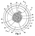
本発明の液体供給体とフィルターとの組立体は、代表的な液体供給体とフィルターとの組立体10の代表的な蓋/フィルターメッシュ部材11などの蓋/フィルターメッシュ部材を含む。本発明の蓋/フィルターメッシュ部材は、図2に示されるような取り外し可能に取り付けられたフィルターメッシュ部材を含む。図2は、図1の代表的な液体供給体とフィルターとの組立体10中に示される代表的な蓋/フィルターメッシュ部材11の底面図である。図2に示されるように、代表的な蓋/フィルターメッシュ部材11は、蓋40を含む。蓋40は、典型的には、ポリプロピレンなどのプラスチック材料から形成された射出成形部品を含む。内面28および内面28に取り付けられた他の部材を見ることができるように、望ましくは蓋40は透明である。
A. Lid / Filter Mesh Member The liquid supply / filter assembly of the present invention comprises a lid / filter mesh member such as a typical lid /
蓋40は、あらゆる所望の形状を有するように形成することができる。好適な形状としては、円錐形、円筒形、長方形の断面領域を有する管型、または正方形の断面領域を有する管型が挙げられるが、これらに限定されるものではない。図1〜図8に示されるような望ましい一実施形態においては、蓋40は、第1の端と、第1の端の反対側にある第2の端とを有する円錐形であり、この第2の端は、第1の端断面積よりも小さい第2の端断面積を有する。
The
代表的な蓋/フィルターメッシュ部材11は、フィルターメッシュ30をさらに含み、これはフィルターメッシュ30の外周辺部からタブ長さdtだけ延在するフィルタータブ31を有するフィルターメッシュ30をさらに含む。フィルターメッシュ30は、外周33から内周34まで延在するリッジ表面領域を有する上部蓋レッジ32に沿って蓋40に取り外し可能に取り付けられている。望ましくは、フィルターメッシュ30の外周辺部は、蓋40の内面28に沿うように蓋レッジ32に取り付けられる。望ましい一実施形態においては、上部蓋レッジ32は、実質的に水平面内にある表面領域を有する。
The exemplary lid /
フィルターメッシュ30は、種々の技術を使用して蓋40に取り外し可能に取り付けることができる。フィルターメッシュを蓋に取り外し可能に取り付けるのに好適な技術としては、超音波溶接、あらゆる熱接合技術(たとえば、蓋、フィルターメッシュ、または両方の一部に熱および/または圧力を加える)、接着接合、ステープラーによる固定、スティッチ溶接などが挙げられるが、これらに限定されるものではない。本発明の望ましい一実施形態においては、超音波溶接法を使用して、フィルターメッシュが蓋に取り外し可能に取り付けられる。
The
本明細書において使用される場合、「取り外し可能に取り付けられた」という語句は、フィルターメッシュ部材と蓋との間の付着の程度を表すために使用される。「取り外し可能に取り付けられた」とは、外部の力(たとえば、フィルタータブ31に対する牽引力)が加えられて、フィルターメッシュが蓋から物理的に離されるまで、フィルターメッシュが蓋とともに損なわれずに維持されることを意味する。牽引力などの外部の力が、フィルターメッシュと上部蓋レッジの表面領域との間の接合力を越えると、蓋の上部蓋リッジ表面領域からフィルターメッシュが剥離する。除去されると、そのフィルターメッシュは通常は元に戻すことができない。 As used herein, the phrase “removably attached” is used to describe the degree of adhesion between the filter mesh member and the lid. “Removably attached” means that the filter mesh is maintained intact with the lid until an external force (eg, traction on the filter tab 31) is applied and the filter mesh is physically separated from the lid. Means that. When an external force such as traction force exceeds the bonding force between the filter mesh and the surface area of the upper lid ledge, the filter mesh peels from the upper lid ridge surface area of the lid. Once removed, the filter mesh usually cannot be restored.
フィルターメッシュ30と蓋40との間の接合の程度は、限定されるものではないが、使用されるフィルターメッシュ材料、蓋材料、接合表面領域、および使用される結合の種類などの多数の要因に依存して変動しうる。たとえば、フィルターメッシュが摩耗した縁端部を有する場合、より広い接合表面領域を使用することができ、さらに又はこれに替えて、刻み付きの超音波溶接を使用することができる。より広い刻み付きの超音波溶接によって、フィルターメッシュのあらゆる摩耗した縁端部が捕捉される。摩耗量を最小限にするために、レーザーを使用してフィルターメッシュを切断することができ、これによってフィルターメッシュ材料の縁端部が溶融する。このフィルターメッシュは摩耗があるとしてもその量は最小限であるので、より狭いシーム溶接または接合の領域を使用することができる。望ましくは、シーム溶接または接合の領域は、フィルターメッシュの外周辺部を完全に囲んで延在し、平均シーム幅(すなわち、同じ面内にあり、外周辺部に対して実質的に垂直の寸法)は最大約5.0mmであり、より望ましくは約1.0mm〜約3.0mmの範囲である。
The degree of bonding between the
フィルターメッシュ30および蓋40は、種々の材料から形成することができる。フィルターメッシュ30および蓋40は、類似の材料または異なる材料を含むことができる。好適な材料としては、ポリプロピレン、ポリエチレン、ナイロン、ポリエステル、またはそれらの組み合わせが挙げられるが、これらに限定されるものではない。望ましい一実施形態においては、フィルターメッシュ30はナイロンメッシュ生地から形成され、一方、蓋40は、ポリプロピレンから形成された射出成形部品である。この実施形態においては、ナイロンフィルターメッシュは、望ましくは、超音波溶接技術によってポリプロピレンの蓋に取り外し可能に取り付けられる。超音波溶接中、上部蓋稜線部32の外面層、および/または上部蓋稜線部32の外面層上の図示しないエネルギーダイレクター(energy directors)が溶融することで、フィルターメッシュ30を蓋40に機械的に結合する。ナイロンはポリプロピレンよりも高い溶融温度を有するので、超音波溶接プロセス中のナイロンフィルターメッシュの構造的完全性は維持される。この代表的実施形態においては、上部蓋稜線部32の外面層および/または上部蓋稜線部32の外面層上の図示しないエネルギーダイレクターの一部が、上部蓋稜線部32と隣接するフィルターメッシュ30の一部に入り込んで、フィルターメッシュ30の一部を包み込む。
The
フィルタータブ31も、フィルターメッシュ30および蓋40を形成するために使用される前述の材料から形成することができる。フィルタータブ31は、フィルターメッシュ30の連続部分であってよいし(すなわち、同じ材料から形成されていてよい)、フィルターメッシュ30に物理的、機械的、または接着的に取り付けられた別個の部材であってもよい。望ましくは、フィルタータブ31は、フィルターメッシュ30の連続部分であり、ナイロンも含む(すなわち、代表的なフィルターメッシュ30の形状などの形状にナイロンメッシュ生地から切り取られる)。
The
フィルターメッシュ30およびフィルタータブ31は、所定の用途により変化する寸法および形状を有することができる。フィルターメッシュ30は、限定するものではないが、円形、正方形、長方形、三角形、五角形、星形などのあらゆる所望の形状を有することができる。望ましい一実施形態においては、フィルターメッシュ30は円形である。フィルタータブ31も、あらゆる所望の形状を有することができ、一実施形態においては、長方形または正方形である。フィルタータブ31は、フィルターメッシュ30のどの部分からも延在することができるが、通常はフィルターメッシュ30外周辺部から外側に向かって延在する。
The
フィルターメッシュ30およびフィルタータブ31の寸法は、蓋の大きさに依存して変化させることができる。一実施形態においては、フィルターメッシュ30は、約15mm〜約100mmの範囲の最大寸法(すなわち、長さ、幅、または直径)を有するが、フィルターメッシュ30はこれよりも小さいまたは大きい寸法を有することもできる。一実施形態においては、フィルタータブ31は、約5mm〜約15mmの範囲の最大寸法(すなわち、典型的には長さ)を有することができるが、フィルタータブ31はこれよりも小さいまたは大きい寸法を有することもできる。たとえば、一実施形態において、円形で直径が約56mmのフィルターメッシュは、フィルターメッシュの外周から外側に向かって約10mm延在するフィルタータブを有する。
The dimensions of the
フィルターメッシュ30およびフィルタータブ31を形成するために使用されるメッシュ生地は、典型的には、あらゆる所望の目開きを有するメッシュ織物を含む。一実施形態においては、このメッシュ織物の平均目開きは最大約500ミクロンであり、さらに別の実施形態においては約200ミクロン未満であり、別の実施形態においては約80ミクロン〜約200ミクロンの間である。本発明において使用できる好適なメッシュサイズとしては、約50ミクロン〜約500ミクロンの範囲のあらゆるメッシュサイズ、およびそれらの間のあらゆるサイズが上げられるが、これらに限定されるものではない。本発明において使用される代表的なメッシュサイズとしては、80ミクロン、120ミクロン、および200ミクロンのメッシュフィルターが挙げられるが、これらに限定されるものではない。一実施形態においては、フィルターメッシュ30およびフィルタータブ31が、追加のフィルター部材を全く有さない1枚のメッシュ生地からなり、フィルターメッシュ30はこの1枚のメッシュ生地のより広い部分であり、フィルタータブ31はこの第1のフィルターメッシュから延在している。
The mesh fabric used to form the
図2に示されるように、代表的な蓋/フィルターメッシュ部材11は、蓋40の内面28上にあり、内面28から下向きに延在する1つ以上の保持壁35をさらに含む。典型的には、保持壁35は、蓋40の一部材として一体的に成形されている(すなわち、保持壁35は、蓋40を形成するための成形プロセス中に形成される)。代表的な一実施形態においては、図2に示されるように、蓋40は、蓋40の内面28に沿って延在する2つ以上の保護壁35を含み、ここで、(i)各保持壁35は、保持壁厚さを超える保持壁長さを有し、(ii)各保持壁35は、フィルターメッシュ30の外周辺部に沿って配置されており、(iii)これらの2つ以上の保持壁35の全長は、フィルターメッシュ30の外周辺部の全長よりも短い。
As shown in FIG. 2, the exemplary lid /
図2に示されるように、代表的な蓋/フィルターメッシュ部材11は、上部蓋レッジ32の外周33に沿って互いに等間隔に配置された4つの保護壁35を含む。一実施形態においては、各保持壁35は、厚さが約800ミクロン(μm)〜約1200μmの範囲であり、外周33に沿って一定距離で延在する長さ(すなわち、この代表的実施形態においては、弧の長さ)は約1.0ミリメートル(mm)〜約22.0mmの範囲であり、高さは約1.0mm〜約5.0mmの範囲である。一実施形態においては、保持壁の周囲の流体の流れを妨害しないように(すなわち影響が最小限となるように)、各保持壁35がセグメント化された構成を有する。
As shown in FIG. 2, the exemplary lid /
代表的な蓋/フィルターメッシュ部材11は、内面28の外周辺部に沿った下部蓋レッジ26も含む。図2に示される円周27は、下部蓋レッジ26と蓋40の内面28との境界を示している。蓋40の内面28は、蓋40の円錐形部分に沿って上方に延在している。内面28は、中を貫通する蓋開口部91を有する円筒形部分24の内面29(図1の円筒形部分24参照)まで延在している。
The exemplary lid /
蓋40の内面28と、円筒形部分24の内面29との間の境界付近にあり、通常は円筒形部分24の内面29に沿っている、半径方向内側に向かって延在する1つ以上の部材36を配置することができる。前述の保持壁と同様に、延在部材36は、通常は、蓋40の一部材として一体的に成形されている(すなわち、延在部材36は、蓋40を形成するための成形プロセス中に形成される)。フィルターメッシュ30を蓋40から分離した後に、別個の第2の濾材を蓋40に取り付けるために、延在部材36を使用することができる(後述する)。
One or more radially inwardly extending near the boundary between the
一実施形態においては、フィルターメッシュ30は、フィルターメッシュ30の外周辺部に囲まれたフィルターメッシュ表面領域を有し、このフィルターメッシュ表面領域は、蓋40の第1の端から蓋40の第2の端まで延在する開口部の最小断面積よりも大きい。代表的な蓋/フィルターメッシュ部材11においては、蓋40の第1の端から蓋40の第2の端まで延在する開口部の最小断面積は、開口部91の断面積である。代表的な一実施形態においては、蓋40が円錐形であり、開口部91は円形の断面形状を有し、フィルターメッシュ30は円形である。さらに別の代表的実施形態においては、開口部91は、蓋40の第1の端から蓋40の第2の端までの中央部分を通り抜けて延在し、フィルターメッシュ30は、フィルターメッシュ30の外周辺部に囲まれたフィルターメッシュ表面領域を有し、このフィルターメッシュ表面領域は開口部91の断面積よりも大きい。
In one embodiment, the
図1に示されるように、蓋/フィルターメッシュ部材は、(i)液体噴射装置に接続可能である、または(ii)液体噴射装置に接続可能なアダプターに接続可能である、1つ以上の部材をさらに含むことができ、これらの1つ以上の部材は、外面上で蓋部材の第2の端に配置される。たとえば、代表的な蓋/フィルターメッシュ部材11に示されるように、蓋/フィルターメッシュ部材は、円筒形部分24の外面に沿ってボス47上に配置された、軸方向に間隔を開けて半径方向外側に突出するシーリングリング43と、突出するフック部材49の遠位端上で互いに対向して内側に突出するリップ52とを含むことができ、これらは、代表的な蓋/フィルターメッシュ部材11の外面22から延在する円筒形部分24のいずれかの側から、およびそれらの側の上で、等間隔に配置されている。
As shown in FIG. 1, the lid / filter mesh member is one or more members that are connectable to (i) a liquid ejector or (ii) an adapter connectable to the liquid ejector The one or more members are disposed on the outer surface at the second end of the lid member. For example, as shown in representative lid /
上述の形状の部材を使用することで、蓋/フィルターメッシュ部材を、米国特許第6,536,687号明細書に記載される噴射装置に取り付けることができる(特に図1〜図3、および本発明の蓋/フィルターメッシュ部材を噴射装置に取り付けるための代表的システムの説明に関する添付の開示を参照されたい)。 By using a member of the shape described above, the lid / filter mesh member can be attached to the injection device described in US Pat. No. 6,536,687 (particularly FIGS. 1-3 and the book). See the accompanying disclosure for a description of an exemplary system for attaching the inventive lid / filter mesh member to the injector).
図2の線3−3に沿って示される代表的な蓋/フィルターメッシュ部材11の断面図が図3である。図3に示されるように、フィルタータブ31を有するフィルターメッシュ30が、蓋40の円筒形部分24から距離Lfで配置されている。理解すべきであるが、フィルタータブ31を有するフィルターメッシュ30は、円筒形部分24から距離Lfで配置することができ、Lfは、約0.0mm〜Lcまでの範囲であり、Lcは、円筒形部分24から蓋40の下部蓋レッジ26までの総距離である。一実施形態においては、Lcは最大約45mmであり、フィルタータブ31を有するフィルターメッシュ30は、円筒形部分24から距離Lfで配置され、Lfは約10.0mm〜約25mmの範囲である。Lcが約45mmである代表的な一実施形態においては、Lfが約25mmである。
A cross-sectional view of an exemplary lid /
図2〜図3には示されていないが、蓋/フィルターメッシュ部材11は、2つ以上の取り外し可能に取り付けられたフィルター部材(たとえば、フィルタータブ31を有する2つ以上のフィルターメッシュ30)を含むことができることに留意されたい。代表的な一実施形態においては、蓋/フィルターメッシュ部材11は、(i)図2〜図3に示されるようなフィルタータブ31を有するフィルターメッシュ30などの第1の取り外し可能に取り付けられたフィルター部材と、(ii)フィルタータブ31を有するフィルターメッシュ30に類似しており、蓋40の下部蓋レッジ26に沿って取り付けられる第2の取り外し可能に取り付けられたフィルター部材とを含む。この代表的実施形態においては、これらのフィルター部材は、互いに類似している場合もあるし(たとえば、両方のフィルター部材がフィルターメッシュ材料であってよい)、互いに異なる場合もある(たとえば、フィルターメッシュ材料と図6に示されるような濾材)。
Although not shown in FIGS. 2-3, the lid /
2つ以上のフィルター部材を有する一実施形態においては、蓋/フィルターメッシュ部材は、(i)上部蓋レッジ(上部蓋レッジ32など)に沿って配置された第1のフィルタータブを有する第1のフィルターメッシュを含む第1の取り外し可能に取り付けられたフィルター部材と、(ii)下部蓋レッジ(下部蓋レッジ26など)に沿って配置された第2のフィルタータブを有する第2のフィルターメッシュを含む第2の取り外し可能に取り付けられたフィルター部材とを含み、第1のフィルターメッシュは、第2のフィルターメッシュよりも小さいメッシュサイズを有する。たとえば、代表的な一実施形態においては、上部蓋レッジ(上部蓋レッジ32など)に沿って配置された第1のフィルタータブを有する第1のフィルターメッシュは、直径が約56mmであり、メッシュサイズが約80ミクロンであり、1つ以上の保持壁(たとえば、図3中の蓋40の保持壁35)によって部分的に囲まれており、一方、下部蓋レッジ(下部蓋レッジ26など)に沿って配置された第2のフィルタータブを有する第2のフィルターメッシュは、直径が約96mmであり、メッシュサイズが約200ミクロンであり、蓋の内壁面(たとえば、図3中の蓋40の下部16)によって囲まれている。
In one embodiment having two or more filter members, the lid / filter mesh member includes: (i) a first filter tab having a first filter tab disposed along an upper lid ledge (such as upper lid ledge 32). A first removably attached filter member including a filter mesh and (ii) a second filter mesh having a second filter tab disposed along a lower lid ledge (such as the lower lid ledge 26). The first filter mesh has a smaller mesh size than the second filter mesh. For example, in one exemplary embodiment, a first filter mesh having a first filter tab disposed along an upper lid ledge (such as upper lid ledge 32) is about 56 mm in diameter and has a mesh size. Is approximately 80 microns and is partially surrounded by one or more retaining walls (eg, retaining
B.容器
本発明の液体供給体とフィルターとの組立体は、代表的な液体供給体とフィルターとの組立体10の容器12などの容積をさらに含む。この容器は、通常、少なくとも1つの容器側壁と、容器底端と、容器開口部を中に有する容器上端と、少なくとも1つの容器側壁に沿って延在する第1の組のねじ山とを有する。代表的な一実施形態においては、容器12は、1種類以上の液体を収容可能なタンクとして機能し、この容器は、少なくとも1つの容器側壁、容器底端、またはその両方の中に、閉止可能な開口部をさらに含む。さらに別の実施形態においては、容器12がライナーを支持しており、このライナーは1種類以上の液体を収容することができる。
B. Container The liquid supply and filter assembly of the present invention further includes a volume, such as the
図1に示されるように、代表的な容器12は、上端41および底端42を有する略円筒形の側壁48と、側壁48の底端42にわたって延在して底端を閉じる底壁44、側壁48の上端41の周囲の上面15とを含む。側壁48の上端41は、容器12内の開口部を画定している。1種類以上の液体の間で所定の比率が得られるように、容器12(またはライナー13)に逐次注ぐべき1種類以上の液体の量などを示す表示25を側壁48が有することができる。望ましくは、側壁48を通して容器12中の液体量が見られるように、側壁48が十分に透明であり、これは、表示25によって示される所望の量まで液体を加えるのに役立つ。側壁48は、商標、ブランド名などの他の種類の表示を有することもできる。
As shown in FIG. 1, an
容器は、1つ以上のさらなる特徴をさらに含むことができる。図1に示される代表的な容器12などの代表的な一実施形態においては、容器12は、上端41において側壁48の外面に沿ってねじ山21をさらに含む。前述したように、ねじ山21は、液体供給体とフィルターとの組立体の他の部材(たとえば、蓋/フィルターメッシュ部材11、ライナー13、および/またはカラー20)に容器12を固定するために使用される。図1に示される代表的な容器12などのさらに別の代表的実施形態においては、容器12は、底壁44中に開口部45を含む。開口部45は、容器12内に入れられたライナーに到達するために使用することができる。たとえば、容器内に入れられた折りたたみ可能なライナー中の流体の流体流を改善するために、使用者は、容器12中の開口部45を通してライナーに接触し、ライナーに孔を開けることで、ライナー内に空気を送り込むことができるが、ほとんどの場合、十分な流体流が得られるのでライナーに孔を開ける必要はない。開口部45が存在する場合、これは通常円形であり、全体の直径が約3.0cmであるが、開口部45は、あらゆる寸法および/または形状を有することができる。さらに、開口部45が存在する場合、これを閉じることもできる。
The container can further include one or more additional features. In an exemplary embodiment, such as the
容器12は、ポリエチレンまたはポリプロピレンなどのプラスチック材料から形成することができ、透明、半透明(図1に示されるように)、または不透明であってよく、あらゆる好適な大きさであってよい。塗料スプレーガンとともに使用される場合、容器は、通常、約250ml、500ml、または800mlの容量を有するが、他の大きさであってもよい。
The
本発明の液体供給体とフィルターとの組立体は、容器とともにライナー(後述)を含むこともできる。別の実施形態においては、本発明の液体供給体とフィルターとの組立体はライナーを含まない。この実施形態においては、容器が閉止可能な開口部を含む(すなわち、開口部45と類似しているが、開口部を閉じるために使用される独立した部材または取り付けられた部材(図示せず)を有する)。閉止可能な開口部によって、液体を漏らすことなく、ライナーのない容器中に塗料などの液体を注ぐことが可能になる。容器の開放端(すなわち、上端41)に向けて液体を流すために容器をひっくり返した後は、閉止部材を開口部から取り外して、容器内が真空にならないようにすることで、液体の流れを促進することができる。必要に応じて、この閉止部材は、開口部内に戻して、開口部を再度封止することができる。 The assembly of the liquid supply body and the filter of the present invention can also include a liner (described later) together with the container. In another embodiment, the liquid supply and filter assembly of the present invention does not include a liner. In this embodiment, the container includes a closable opening (i.e., similar to opening 45, but a separate or attached member used to close the opening (not shown)). Have). The closable opening allows liquid such as paint to be poured into a container without a liner without leaking the liquid. After the container is turned over to flow the liquid toward the open end of the container (i.e., the upper end 41), the closing member is removed from the opening so that the interior of the container is not evacuated. Can be promoted. If necessary, the closing member can be returned into the opening to re-seal the opening.
C.ライナー
本発明の液体供給体とフィルターとの組立体は、代表的な液体供給体とフィルターとの組立体10のライナー13などのライナーをさらに含むことができる。ライナーが存在する場合、ライナーは、望ましくは、少なくとも1つのライナー側壁と、ライナー底端と、ライナー開口部を中に有するライナー上端と、ライナー上端に沿って延在しライナー上端から突出しているライナーリムとを有する。ライナーが使用される場合、ライナーは1種類以上の液体を収容可能なタンクとして機能する。
C. Liner The liquid supply and filter assembly of the present invention may further include a liner, such as the
図1に示されるように、代表的なライナー13は、容器12の内側と類似した外形を有し、容器上面15上に載せることができるライナーリム14をその開放端に有する。ライナー13は、望ましくは自立型で、折りたたみ可能である。代表的な一実施形態においては、ライナー13は、比較的剛性の高い底部13Aと、比較的薄い側壁13Bとを有し、そのためライナー13を折りたたむ場合、底部ではなく側壁が折りたたまれるため、長手方向にライナー13が折りたたまれる。さらに、ライナー13は、望ましくはひだ、波形、継ぎ目、結合部、およびガセットを有さず、側壁13Bと底部13Aとの内部接合部における溝も有さない。
As shown in FIG. 1, a
典型的には、ライナー13は、ポリプロピレンまたはポリエチレンなどのポリマー材料を含み、熱成形法などの成形法によって形成される。本発明の一実施形態においては、ライナー13は、熱成形された低密度ポリエチレンを含む。
Typically, the
本発明の一実施形態においては、液体供給体とフィルターとの組立体は、ライナー13などのライナーを、前述の容器12などの容器とともに含む。この実施形態においては、塗料などの液体は、ライナーの内壁ととも接触する。さらに、この実施形態においては、容器12は、通気口付き容器であり、すなわち、容器12は容器底壁44中に開口部(たとえば、図1に示される開口部45)を含む。折りたたみ可能なライナーが通気口付き容器(すなわち、図1に示される開口部45などの開口部を含む容器)と併用される場合、そのような組立体では、ライナーから非常に優れた液体流が得られる。
In one embodiment of the present invention, the liquid supply and filter assembly includes a liner such as
D.カラー
本発明の液体供給体とフィルターとの組立体は、代表的な液体供給体とフィルターとの組立体10のカラー20などのカラーをさらに含むことができる。カラーが存在する場合、一実施形態においては、カラーは、カラー開口部を中に有する上端と、底端、上端と底端との間に延在する少なくとも1つのカラー側壁と、上端に沿って延在するカラー開口部内に突出しているカラーリムと、少なくとも1つのカラー側壁に沿って延在する第2の組のねじ山とを有し、この第2の組のねじ山は容器上の第1の組のねじ山(前述)と係合することができる。
D. Color The liquid supply and filter assembly of the present invention can further include a color, such as the
図1に示され、前述したように、カラー20は、上部リム18と、カラー20の内面上に配置されたカラーねじ山19とを含む。上部リム18およびカラーねじ山19は容器ねじ山21とともに機能することで、液体供給体とフィルターとの組立体の蓋/フィルターメッシュ部材11およびライナー13を固定する。
As shown in FIG. 1 and described above, the
カラー20は、成形プラスチック部材であってもよいし、機械加工された金属(たとえば、アルミニウム)部材であってもよい。一実施形態においては、カラー20は、ガラス繊維強化ポリプロピレンを含む成形プラスチック部材である。
The
図4に示される本発明のさらに別の代表的実施形態においては、別の設計の蓋40のために、カラー20が不溶である。この実施形態においては、蓋部材は、蓋部材の第1の端に近接する蓋部材の外面に沿って延在する第2の組のねじ山を含む。この第2の組のねじ山は、容器上の第1の組のねじ山(前述)と係合することができる。
In yet another exemplary embodiment of the present invention shown in FIG. 4, the
図4に示されるように、代表的な液体供給体とフィルターとの組立体100は、蓋400と保護壁35によって部分的に固定されたフィルターメッシュ30とを含む蓋/フィルターメッシュ部材110を含む。蓋400は、円筒形部分24の反対側の端402の内面に沿って配置された内部ねじ山401を含む。内部ねじ山401は、容器12の上端41における側壁48上の容器ねじ山21と係合することで、蓋400と容器12との間にライナー13を固定する。
As shown in FIG. 4, an exemplary liquid supply and
E.交換用濾材
本発明の液体供給体とフィルターとの組立体は、図6に示される濾材60などの交換用濾材をさらに含むことができる。はじめに図5を参照すると、図5は、フィルターメッシュ30を蓋40から除去した(すなわち剥離)後の、図2の代表的な蓋/フィルターメッシュ部材の断面線3−3に沿って見た拡大断面図である。フィルターメッシュを取り外した後、使用者は、1種類以上の液体を濾過することなく1種類以上の液体を利用するために蓋40を使用することを選択することができる。使用者が、濾過した1種類以上の液体を利用するために蓋40を使用することを望む場合は、使用者が、図6に示されるような交換用濾材を取り付けることができる。
E. Replacement Filter Medium The liquid supply and filter assembly of the present invention can further include a replacement filter medium such as the
図6は、交換用濾材60が取り付けられた代表的な蓋40の拡大断面図である。交換用濾材60は、上部端63を有する剛性ポリマーの円筒形枠部分61を含み、この上部端63は、円筒形部分24の内面29に沿って配置され半径方向内側に向かって延在する1つ以上の部材36と係合する。交換用濾材60は、円筒形枠部分61の周囲に沿って延在するフィルタースクリーン62も含む。交換用濾材60と類似した交換用濾材の例は、米国特許第6,536,687号明細書に開示されており、その主題全体が本明細書に援用される。
FIG. 6 is an enlarged cross-sectional view of a
II.液体供給体とフィルターとの組立体の製造方法
代表的な一実施形態においては、液体供給体とフィルターとの組立体の製造方法は、(a)1種類以上の液体を収容可能なタンクに係合するのに適した第1の端、第1の端の反対側に位置し、第1の端断面積よりも小さい第2の端断面積を有する第2の端、第1の端から第2の端までそれぞれ延在する内面および外面、並びに第1の端から第2の端まで蓋部材の中央部分を通り抜けて延在する開口部を含む蓋部材を提供するステップと、(b)少なくとも1つの着脱自在のフィルター部材を蓋部材の内面に取り付けるステップとを含み、少なくとも1つの着脱自在のフィルター部材は、フィルターメッシュ、およびフィルターメッシュから延在するフィルタータブを含む。
II. Manufacturing method of assembly of liquid supply body and filter In a typical embodiment, a manufacturing method of an assembly of a liquid supply body and a filter involves (a) a tank capable of storing one or more types of liquids. A first end suitable for joining, a second end located on the opposite side of the first end and having a second end cross-sectional area smaller than the first end cross-sectional area, from the first end to the second end Providing a lid member comprising an inner surface and an outer surface respectively extending to two ends and an opening extending through a central portion of the lid member from a first end to a second end; (b) at least Attaching one removable filter member to the inner surface of the lid member, wherein the at least one removable filter member includes a filter mesh and a filter tab extending from the filter mesh.
蓋部材を提供するステップは、単純に、商業的供給元から蓋部材を入手することを含むことができる。あるいは、蓋部材を提供するステップは、蓋部材を形成することを含むことができる。前述したように、通常、蓋部材は、射出成型法によって形成され、この方法では、蓋部材の所望の構造に実質的に類似した構造を有する型にポリマー材料が射出される。しかし、射出成型法などのあらゆる公知の成形方法を使用して、蓋部材を形成することができる。 Providing the lid member can simply include obtaining the lid member from a commercial source. Alternatively, providing the lid member can include forming the lid member. As previously mentioned, the lid member is typically formed by an injection molding process, in which the polymeric material is injected into a mold having a structure substantially similar to the desired structure of the lid member. However, the lid member can be formed using any known molding method such as an injection molding method.
前述したように、着脱自在のフィルター部材を蓋部材の内面に取り付ける方法は、限定するものではないが、超音波溶接、あらゆる熱接合技術(たとえば、たとえば、蓋、フィルターメッシュ、または両方の一部に熱および/または圧力を加えて溶融させる)、接着接合、ステープラーによる固定、スティッチ溶接等のあらゆる接合方法を含むことができる。望ましくは、超音波溶接法を使用して、少なくとも1つの着脱自在のフィルター部材が、蓋部材に取り外し可能に取り付けられる。 As described above, the method of attaching the removable filter member to the inner surface of the lid member is not limited, but includes ultrasonic welding, any thermal bonding technique (eg, lid, filter mesh, or part of both And any bonding method such as adhesive bonding, fixing with a stapler, stitch welding, and the like. Desirably, at least one removable filter member is removably attached to the lid member using ultrasonic welding.
代表的な超音波溶接法の1つにおいては、フィルターメッシュ30およびフィルタータブ31などのフィルター部材を、蓋部材に接触させる。上部蓋レッジ(上部蓋レッジ32など)の上に配置する場合、保持壁(保持壁35)が障壁となり、フィルター部材を所望の位置から動かせなくなる。図面には示していないが、上部蓋レッジ32などの蓋レッジは、望ましくは、蓋レッジの外面に沿って複数のエネルギーダイレクターを含む。エネルギーダイレクターは、通常、射出成形法などの成形プロセス中に形成され、蓋レッジの外面に沿って隆起した領域のことである。一実施形態においては、代表的なエネルギーダイレクターは、角錐型であり、高さが約0.38mm、辺長さが約0.76mm、および側壁の傾斜(すなわち、角錐構造の側壁と蓋レッジ外面との間の角度)が約45度である。
In one of the typical ultrasonic welding methods, filter members such as the
超音波溶接中、エネルギーダイレクター上にエネルギーを集中させることで、蓋レッジの外面が溶融する前にエネルギーダイレクターが溶融する。この結果得られる構造において、エネルギーダイレクター内のポリマーは、フィルター部材内に入って、フィルター部材を蓋部材に「機械的に」接合させる一次材料となる。本明細書において使用される場合、用語「機械的に接合する」は、蓋とフィルター部材との間の接合を表すために使用され、この場合、蓋の一部(たとえば、エネルギーダイレクター)が溶融し、フィルター部材の一部に浸透することによって、フィルター部材の一部を包み込む。蓋部材の溶融温度未満に冷却すると、その蓋部材が固化して、固化した蓋部材の中にフィルター部材の一部が取り込まれる。ポリプロピレンの蓋とおよびナイロンのメッシュフィルターとが使用される一実施形態においては、ポリプロピレンがナイロンよりも低い溶融温度を有するため、ポリプロピレンがナイロン繊維の周囲で溶融してナイロン繊維を包み込む。言い換えると、ポリマー間の機械的接合は、ポリマーが分子レベルでは混合していない接合である。 During ultrasonic welding, the energy director is melted before the outer surface of the lid ledge is melted by concentrating energy on the energy director. In the resulting structure, the polymer in the energy director becomes the primary material that enters the filter member and “mechanically” joins the filter member to the lid member. As used herein, the term “mechanically joined” is used to describe a joint between a lid and a filter member, where a portion of the lid (eg, an energy director) is used. A part of the filter member is wrapped by melting and permeating a part of the filter member. When cooled below the melting temperature of the lid member, the lid member is solidified, and a part of the filter member is taken into the solidified lid member. In one embodiment where a polypropylene lid and a nylon mesh filter are used, the polypropylene has a lower melting temperature than nylon so that the polypropylene melts around the nylon fiber to enclose the nylon fiber. In other words, a mechanical bond between polymers is a bond where the polymers are not mixed at the molecular level.
本発明においてはあらゆる超音波溶接装置を使用することができる。好適な市販の超音波溶接装置としては、ブランソン・ウルトラソニック・コーポレーション(Branson Ultrasonic Corporation)(コネチカット州ダンベリー(Danbury,CT))より市販されるウェルダー・モデル・ブランソン2000aed2.5(welder model Branson 2000 aed 2.5)などの超音波溶接装置が挙げられるが、これらに限定されるものではない。 Any ultrasonic welding apparatus can be used in the present invention. Suitable commercially available ultrasonic welding equipment include Welder Model Branson 2000aed 2.5 (welder model Branson 2000 aed), commercially available from Branson Ultrasonic Corporation (Danbury, CT). 2.5) and the like, but are not limited thereto.
1つ以上のフィルター部材を蓋部材に取り付けた後、蓋/フィルターメッシュ部材を、前述したような液体供給体とフィルターとの組立体の他の部材とさらに組み合わせることができる。ライナー(または閉止可能な開口部を有する)に1種類以上の液体を入れた後、液体供給体とフィルターとの組立体を、前述のような噴射装置に取り付けることができる。 After attaching one or more filter members to the lid member, the lid / filter mesh member can be further combined with other members of the liquid supply and filter assembly as described above. After one or more liquids have been placed in the liner (or with a closable opening), the liquid supply and filter assembly can be attached to an injection device as described above.
III.液体供給体とフィルターとの組立体の使用方法
前述の液体供給体とフィルターとの組立体を使用して液体を基材上に適用する方法も開示する。前述の液体供給体とフィルターとの組立体は、あらゆる種類の噴射装置への使用に適しているが、図7に示される代表的な噴射装置70、ならびに国際公開第98/32539号パンフレット、米国特許第6,536,687号明細書、および米国特許第6,588,681号明細書に開示される類似の重力供給される噴射装置などの重力供給される噴射装置において特に有用である。
III. Method of Using Liquid Supply and Filter Assembly Also disclosed is a method of applying liquid onto a substrate using the liquid supply and filter assembly described above. The liquid supply and filter assembly described above is suitable for use in all types of injection devices, but the
噴射装置は、限定するものではないが、アネスト・イワタUSAインコーポレイテッド(Anest Iwata USA Inc.)(オハイオ州ウエストチェスター(West Chester,OH))などの多数の供給元から市販されている。代表的な市販の噴射装置の1つは、アネスト・イワタUSAインコーポレイテッド(Anest Iwata USA Inc.)(オハイオ州ウエストチェスター(West Chester,OH))より商品名W400で入手可能である。 Injectors are commercially available from a number of sources such as, but not limited to, Anest Iwata USA Inc. (West Chester, Ohio). One exemplary commercially available injector is available under the trade name W400 from Anest Iwata USA Inc. (West Chester, Ohio).
図7に示されるように、代表的な液体供給体とフィルターとの組立体10は、アダプター34を介して代表的な噴射装置70に取り付けることができる。アダプター34は、蓋40の円筒形部分24の上に取り付けられ、蓋40の突出するフック部材49の遠位端上で互いに対向して内側に突出するリップ52と係合する。アダプター34、および代表的な液体供給体とフィルターとの組立体10と代表的な噴射装置70との間の接続のより詳細な図が図8に示されている。
As shown in FIG. 7, the representative liquid supply and
図8に示されるように、代表的なアダプター34は、第1および第2の隔置された端部分36および38を含み、端部分36および38を通り抜けて延在する貫通開口部88を有する。アダプター34の第1の端部分36は、内部ねじ山(図示せず)と、第1の端部分36の周囲のレンチが係合可能な6つの平坦面部分42とを有し、これによって、代表的な噴射装置70の入口81上の外部ねじ山に取り外し可能に係合するよう適合させることができる。蓋40とアダプター34の第2の端部分38とは、互いに連絡する貫通開口部91および88に取り外し可能に液密係合するように適合させたコネクター部分を有する。
As shown in FIG. 8, the
係合させると、シーリングリング43を有する蓋40の円筒形部分24は、アダプター34の内面444と液密係合状態にある。さらに、アダプター34の第2の端部分38の周囲のアダプターカラー145上の横断面46は、円筒形部分24の周囲にある蓋40のボス47に隣接する。アダプター34の開口部88内に向けて軸方向に円筒形部分24を押し込むときに、円筒形部分24の互いに反対側において蓋40の外面22から突出するフック部材49の遠位端を通過するように適合した、互いに反対側に沿って大きな円筒形の凹状くぼみ148を、アダプターカラー145が有する。この時点で、蓋40およびアダプター34は、フック部材49がアダプターカラー145の大きな窪み148と位置合わせされる、第1の相対位置にある。次に、蓋40およびアダプター34を第2の相対位置まで互いに回転させることで、弾性的に可撓性の突出するフック部材49を、小さな凹状窪み51の周囲で移動させ、小さな凹状窪み51の中に入るようにすることができる。この第2の相対位置において、突出するフック部材49は、アダプターカラー145中の小さな円筒形の凹状窪み51内にあり、一方、突出するフック部材49の遠位端上の互いに対向して内側に突出するリップ52は、アダプター34の第1の端36に隣接するアダプターカラー145の表面53上で係合する。
When engaged, the
アダプター34は、ポリマーまたは金属の材料から形成することができる材料。望ましい一実施形態においては、アダプター34は金属材料(たとえば、ステンレス鋼)から形成される。
The
前述の接続ステップの開始前、または前述の接続ステップを部分的に終了した後で、容器12中に各液体が逐次注がれて1種類以上の液体の間で所望の比率が得られるような量を示す表示25を使用して、最初に使用者は、容器12中で1種類以上の液体を混合することができる。1種類以上の液体を測定する場合に使用者を補助するために、あらゆる表示25を容器12上に使用することができる。本発明における使用に適した代表的な表示の1つは、米国特許第6,588,681号明細書に開示される表示(すなわち、米国特許第6,588,681号明細書の図1に示される表示シート24上の表示25)を含んでいる。
Each liquid is sequentially poured into the
通常は、1種類以上の液体は、前述のライナー13中に入れられる。別の実施形態においては、1種類以上の液体が容器12に直接入れられる。この実施形態においては、ライナー13は使用されず、その代わりに、図4に示される代表的な蓋/フィルターメッシュ部材110に類似した蓋/フィルターメッシュ部材が、1種類以上の液体を収容する容器12に直接取り付けられる。
Usually, one or more liquids are placed in the
ライナー13が使用される場合、容器12内に入れる前または後でライナー13を満たすことができる。ライナー13または容器12を所望の量まで満たした後、蓋/フィルターメッシュ部材11または110を、それぞれライナー13または容器12と係合させる。蓋/フィルターメッシュ部材11が使用される場合、ライナー13に係合させた後、前述のようにカラー20を容器12上にねじ込む。液体供給体とフィルターとの組立体を組み立てた後、液体供給体とフィルターとの組立体を前述のような噴射装置に接続することができる。
If a
本発明の液体供給体とフィルターとの組立体を噴射装置に接続した後、図7に示されるように噴射装置をひっくり返すと使用できる状態になる。重力によって、ライナー13(または閉止可能な開口部を有する容器12)中の1種類以上の液体が噴射装置70内に供給される。前述したように、この使用方法は、剛性底部13A(または容器12の場合は底端42)の近くでライナー13に孔を開けて(または容器12中の閉止装置を取り外して)、液体をスプレーするときにライナー13(または閉止可能な開口部を有する容器12)中に空気を送り込み、ライナー13(または閉止可能な開口部を有する容器12)中の真空形成を最小限にする、または形成しないようにすることをさらに含むことができる。しかし、ライナー13の孔開けは不要であり、ほとんどの場合、推奨されない。噴射装置70の使用後にライナー13(または閉止可能な開口部を有する容器12)中に液体が残存する場合、必要であれば、ピンまたはその他の物体を孔の開いた領域に挿入して、ライナー13からの液体の漏れを制限することができる(または容器12に閉止装置を戻すこともできる)。
After the assembly of the liquid supply body and the filter of the present invention is connected to the ejection device, the ejection device is turned over as shown in FIG. One or more types of liquid in the liner 13 (or the
所定のスプレー作業が終了すると、ライナー13(または閉止可能な開口部を有する容器12)中に残留する液体が、蓋/フィルターメッシュ部材11または110と接触しないような位置に、噴射装置11を反転させることができる。この位置で、コネクター部材を外すことができる。残留した液体(触媒のない場合)は、必要に応じて、後に使用するためにライナー13(または閉止可能な開口部を有する容器12)中に保管することができる。蓋/フィルターメッシュ部材11または110、ライナー13、容器12、および/またはカラー20は、清浄にして再使用することもできるし、単に廃棄することもできる。
When the predetermined spraying operation is completed, the
本明細書は特定の実施形態に関して詳細に説明してきたが、以上に記載のことを理解すれば、当業者には、これらの実施形態の変更、変形、および均等物を容易に考え出すことができることが分かるであろう。したがって、本発明の範囲は、添付の特許請求の範囲およびそれらのあらゆる均等物の範囲であると評価すべきである。 Although the present specification has been described in detail with reference to particular embodiments, those skilled in the art can readily devise modifications, variations, and equivalents of these embodiments upon understanding the foregoing. You will understand. Accordingly, the scope of the invention should be assessed as that of the appended claims and any equivalents thereto.
Claims (37)
1種類以上の液体を収容可能なタンクに接続するのに適した第1の端、
前記第1の端の反対側にある第2の端、
前記第1の端から前記第2の端まで延在する内面および外面、並びに
前記第1の端から前記第2の端まで前記蓋部材の一部を通り抜けて延在する開口部を含む、蓋部材と、
前記蓋部材の前記内面に取り付けられた、第1の取り外し可能に取り付けられたフィルター部材とを含み、
前記第1の取り外し可能に取り付けられたフィルター部材が第1のフィルターメッシュ、および前記第1のフィルターメッシュから延在する第1のフィルタータブを含む、
組立体。 An assembly of a liquid supply and a filter,
A first end suitable for connection to a tank capable of containing one or more liquids;
A second end opposite the first end;
A lid including an inner surface and an outer surface extending from the first end to the second end, and an opening extending through a portion of the lid member from the first end to the second end. Members,
A first removably attached filter member attached to the inner surface of the lid member;
The first removably attached filter member includes a first filter mesh and a first filter tab extending from the first filter mesh;
Assembly.
フィルターメッシュと、
前記フィルターメッシュから延在するフィルタータブとを含む、請求項10に記載の組立体。 The at least one other removably attached filter member comprises:
Filter mesh,
The assembly of claim 10 including a filter tab extending from the filter mesh.
1種類以上の液体を収容可能なタンクに接続するのに適した第1の端、
前記第1の端の反対側にある第2の端、
前記第1の端から前記第2の端までそれぞれ延在する内面および外面、並びに
前記第1の端から前記第2の端まで前記蓋部材の一部を通り抜けて延在する開口部を含む、蓋部材と、
前記蓋部材の前記内面に取り付けられた、第1の取り外し可能に取り付けられたフィルター部材とを含み、
前記第1の取り外し可能に取り付けられたフィルター部材が第1のフィルターメッシュ、および前記第1のフィルターメッシュから延在する第1のフィルタータブを含む、
蓋/フィルターメッシュ部材。 A lid / filter mesh member suitable for use in a liquid supply assembly comprising:
A first end suitable for connection to a tank capable of containing one or more liquids;
A second end opposite the first end;
An inner surface and an outer surface respectively extending from the first end to the second end, and an opening extending through a part of the lid member from the first end to the second end; A lid member;
A first removably attached filter member attached to the inner surface of the lid member;
The first removably attached filter member includes a first filter mesh and a first filter tab extending from the first filter mesh;
Lid / filter mesh member.
フィルターメッシュと、
前記フィルターメッシュから延在するフィルタータブとを含む、請求項26に記載の蓋/フィルターメッシュ部材。 And further comprising at least another removably attached filter member attached to the inner surface of the lid member, wherein the at least another removably attached filter member comprises:
Filter mesh,
27. The lid / filter mesh member of claim 26, comprising a filter tab extending from the filter mesh.
前記第1の端の反対側にある第2の端、
前記第1の端から前記第2の端までそれぞれ延在する内面および外面、並びに
前記第1の端から前記第2の端まで前記蓋部材の一部を通り抜けて延在する開口部を含む、蓋部材と、
前記蓋部材の前記内面に取り付けられた、第1の取り外し可能に取り付けられたフィルター部材とを含み、
前記第1の取り外し可能に取り付けられたフィルター部材が第1のフィルターメッシュ、および前記第1のフィルターメッシュから延在する第1のフィルタータブを含む、
蓋/フィルターメッシュ部材と、
(i)少なくとも1つの容器側壁、(ii)容器底端、(iii)容器開口部を中に有する容器上端、および(iv)前記少なくとも1つの容器側壁に沿って延在する第1の組のねじ山を有する、容器と、
(i)少なくとも1つのライナー側壁、(ii)ライナー底端、(iii)ライナー開口部を中に有するライナー上端、および(iv)前記ライナー上端に沿って延在し前記ライナー上端から突出しているライナーリムを有し、1種類以上の液体を収容可能である、オプションのライナーと、
(i)カラー開口部を中に有する上端、(ii)底端、(iii)前記上端と前記底端との間に延在する少なくとも1つのカラー側壁、(iv)前記上端に沿って延在し前記カラー開口部内に突出しているカラーリム、および(v)前記少なくとも1つのカラー側壁に沿って延在し、前記容器上の前記第1の組のねじ山に接続可能である、第2の組のねじ山を有する、オプションのカラーと、を含む、液体供給体とフィルターとの組立体であって、
前記蓋部材、前記容器、前記オプションのライナー、および前記オプションのカラーを、互いに配置し組み合わせることによって、漏れが生じない液体供給体とフィルターとの組立体を形成することができ、前記漏れが生じない液体供給体とフィルターとの組立体が、重力供給される液体噴射装置に接続可能である、液体供給体とフィルターとの組立体。 A first end suitable for connection to a tank capable of containing one or more liquids;
A second end opposite the first end;
An inner surface and an outer surface respectively extending from the first end to the second end, and an opening extending through a part of the lid member from the first end to the second end; A lid member;
A first removably attached filter member attached to the inner surface of the lid member;
The first removably attached filter member includes a first filter mesh and a first filter tab extending from the first filter mesh;
A lid / filter mesh member;
(I) at least one container sidewall, (ii) a container bottom end, (iii) a container top having a container opening therein, and (iv) a first set extending along said at least one container sidewall. A container having a thread;
(I) at least one liner sidewall, (ii) a liner bottom end, (iii) a liner top end having a liner opening therein, and (iv) a liner extending along and protruding from the liner top end. An optional liner having a rim and capable of containing one or more liquids;
(I) a top end having a collar opening therein; (ii) a bottom end; (iii) at least one collar sidewall extending between the top end and the bottom end; and (iv) extending along the top end. A collar rim projecting into the collar opening; and (v) a second set extending along the at least one collar sidewall and connectable to the first set of threads on the container. An assembly of liquid supply and filter, including an optional collar having a thread of
The lid member, the container, the optional liner, and the optional collar can be arranged and combined with each other to form a liquid supply and filter assembly that does not leak, and the leakage occurs. A liquid supply and filter assembly, wherein no liquid supply and filter assembly is connectable to a gravity-fed liquid ejection device.
フィルターメッシュと、
前記フィルターメッシュから延在するフィルタータブとを含む、請求項35に記載の組立体。 And further comprising at least one removably attached filter member attached to the inner surface of the lid member, wherein the at least one other removably attached filter member comprises:
Filter mesh,
36. The assembly of claim 35, comprising a filter tab extending from the filter mesh.
Applications Claiming Priority (2)
| Application Number | Priority Date | Filing Date | Title |
|---|---|---|---|
| US10/992,503 US20060102550A1 (en) | 2004-11-18 | 2004-11-18 | Liquid supply and filter assembly |
| PCT/US2005/037006 WO2006055138A1 (en) | 2004-11-18 | 2005-10-14 | Liquid supply and filter assembly for a spray gun |
Publications (2)
| Publication Number | Publication Date |
|---|---|
| JP2008520425A true JP2008520425A (en) | 2008-06-19 |
| JP2008520425A5 JP2008520425A5 (en) | 2008-11-27 |
Family
ID=35722382
Family Applications (1)
| Application Number | Title | Priority Date | Filing Date |
|---|---|---|---|
| JP2007543051A Withdrawn JP2008520425A (en) | 2004-11-18 | 2005-10-14 | Liquid supply and filter assembly for spray gun |
Country Status (11)
| Country | Link |
|---|---|
| US (1) | US20060102550A1 (en) |
| EP (1) | EP1812170A1 (en) |
| JP (1) | JP2008520425A (en) |
| KR (1) | KR20070084301A (en) |
| CN (1) | CN101060935A (en) |
| AU (1) | AU2005307048A1 (en) |
| BR (1) | BRPI0517763A (en) |
| CA (1) | CA2587105A1 (en) |
| MX (1) | MX2007005814A (en) |
| RU (1) | RU2007117797A (en) |
| WO (1) | WO2006055138A1 (en) |
Cited By (2)
| Publication number | Priority date | Publication date | Assignee | Title |
|---|---|---|---|---|
| JP2019115907A (en) * | 2015-02-20 | 2019-07-18 | カーライル フルイド テクノロジーズ,インコーポレイティド | Adapter for spray device |
| JP2022508439A (en) * | 2018-12-27 | 2022-01-19 | スリーエム イノベイティブ プロパティズ カンパニー | Fluid delivery assembly for spray equipment |
Families Citing this family (44)
| Publication number | Priority date | Publication date | Assignee | Title |
|---|---|---|---|---|
| US7380680B2 (en) * | 2004-01-16 | 2008-06-03 | Illinois Tool Works Inc. | Fluid supply assembly |
| US7086549B2 (en) | 2004-01-16 | 2006-08-08 | Illinois Tool Works Inc. | Fluid supply assembly |
| US7165732B2 (en) | 2004-01-16 | 2007-01-23 | Illinois Tool Works Inc. | Adapter assembly for a fluid supply assembly |
| US7665672B2 (en) | 2004-01-16 | 2010-02-23 | Illinois Tool Works Inc. | Antistatic paint cup |
| US7766250B2 (en) | 2004-06-01 | 2010-08-03 | Illinois Tool Works Inc. | Antistatic paint cup |
| US7757972B2 (en) | 2004-06-03 | 2010-07-20 | Illinois Tool Works Inc. | Conversion adapter for a fluid supply assembly |
| US7353964B2 (en) * | 2004-06-10 | 2008-04-08 | Illinois Tool Works Inc. | Fluid supply assembly |
| CA2595507C (en) | 2004-12-16 | 2014-08-12 | Louis M. Gerson Co., Inc. | Liquid supply cup and liner assembly for spray guns |
| EP1844302A2 (en) * | 2005-01-31 | 2007-10-17 | Illinois Tool Works Inc. | Fluid supply assembly with measuring guide |
| WO2007137257A2 (en) | 2006-05-22 | 2007-11-29 | 3M Innovative Properties Company | System and method for preparing samples |
| US11040360B2 (en) * | 2006-06-20 | 2021-06-22 | Saint-Gobain Abrasives, Inc. | Liquid supply assembly |
| ES2400161T3 (en) | 2006-06-20 | 2013-04-08 | Saint-Gobain Abrasives, Inc. | Liquid supply set |
| WO2009067518A1 (en) * | 2007-11-20 | 2009-05-28 | 3M Innovative Properties Company | Sample preparation container and method |
| CN101909755B (en) * | 2007-11-20 | 2013-09-18 | 3M创新有限公司 | Sample preparation container and method |
| EP2217378B1 (en) | 2007-11-20 | 2013-02-13 | 3M Innovative Properties Company | Sample preparation container and method |
| EP2217377B1 (en) | 2007-11-20 | 2013-09-18 | 3M Innovative Properties Company | Sample preparation for environmental sampling |
| ES2381420T3 (en) * | 2007-12-31 | 2012-05-28 | 3M Innovative Properties Company | Containers that have an external protection sheet |
| DE102008033792B4 (en) * | 2008-07-18 | 2021-04-29 | BSH Hausgeräte GmbH | Air circulation module and extractor device |
| KR101729793B1 (en) | 2009-01-26 | 2017-04-24 | 쓰리엠 이노베이티브 프로퍼티즈 컴파니 | Liquid spray gun, spray gun platform, and spray head assembly |
| TWI506070B (en) | 2009-12-14 | 2015-11-01 | 3M Innovative Properties Co | Microperforated polymeric film and methods of making and using the same |
| CN103370139B (en) | 2011-02-09 | 2017-09-05 | 3M创新有限公司 | Nozzle head and nozzle component for liquid spray gun |
| WO2012154624A2 (en) * | 2011-05-06 | 2012-11-15 | Saint-Gobain Abrasives, Inc. | Paint cup assembly with a collapsible liner |
| MX371278B (en) | 2011-06-30 | 2020-01-24 | Saint Gobain Abrasifs Sa | Paint cup assembly. |
| BR112014001936A2 (en) | 2011-07-28 | 2017-02-21 | 3M Innovative Properties Co | sprinkler head assembly with integrated nozzle / air cap for a liquid spray gun |
| US9802211B2 (en) | 2011-10-12 | 2017-10-31 | 3M Innovative Properties Company | Spray head assemblies for liquid spray guns |
| EP2583715A1 (en) | 2011-10-19 | 2013-04-24 | Unomedical A/S | Infusion tube system and method for manufacture |
| EP2797697B1 (en) | 2011-12-30 | 2020-11-04 | Saint-Gobain Abrasives, Inc. | Convertible paint cup assembly with air inlet valve |
| WO2013134182A1 (en) | 2012-03-06 | 2013-09-12 | 3M Innovative Properties Company | Spray gun having internal boost passageway |
| US11167298B2 (en) | 2012-03-23 | 2021-11-09 | 3M Innovative Properties Company | Spray gun barrel with inseparable nozzle |
| US9352343B2 (en) | 2013-01-22 | 2016-05-31 | Carlisle Fluid Technologies, Inc. | Liquid supply system for a gravity feed spray device |
| AU2014290641B2 (en) | 2013-07-15 | 2017-07-06 | 3M Innovative Properties Company | Air caps with face geometry inserts for liquid spray guns |
| ES2848277T3 (en) | 2013-12-05 | 2021-08-06 | 3M Innovative Properties Co | Container for spraying device |
| US9482599B1 (en) * | 2014-06-20 | 2016-11-01 | Lyle Johnson | Water testing method and apparatus |
| EP3135385B2 (en) * | 2015-08-25 | 2022-02-09 | Andreas Massold | Lid for a container for liquids for a spray gun |
| EP3842154A1 (en) | 2016-01-15 | 2021-06-30 | 3M Innovative Properties Company | Connector system for hand-held spray guns |
| AU2017207358B2 (en) * | 2016-01-15 | 2019-10-31 | 3M Innovative Properties Company | Button-lock fluid connector for hand-held spray guns |
| WO2017123714A1 (en) * | 2016-01-15 | 2017-07-20 | 3M Innovative Properties Company | Wide-mouthed fluid connector for hand-held spray guns |
| US10434527B1 (en) * | 2017-10-05 | 2019-10-08 | EMM Holding BV | Fluid dispensing system |
| US10919676B2 (en) | 2019-05-02 | 2021-02-16 | Emm Holding B.V. | Lid with ventilation system |
| CN212263685U (en) * | 2019-11-21 | 2021-01-01 | 泰信贸易株式会社 | Disposable paint spraying mixing cup |
| JP2021087920A (en) * | 2019-12-05 | 2021-06-10 | スリーエム イノベイティブ プロパティズ カンパニー | Lid for storage container, filter insertion member, storage container and method for manufacturing lid for storage container |
| USD971729S1 (en) | 2020-03-12 | 2022-12-06 | 3M Innovative Properties Company | Container lid |
| USD952097S1 (en) * | 2020-07-14 | 2022-05-17 | Yuyao Yufeng Scutcheon Plastic Factory | Paint spraying pot lid |
| DE102020120231A1 (en) | 2020-07-31 | 2022-02-03 | Sata Gmbh & Co. Kg | Gravity cup with an inner bag that can be used as an option |
Family Cites Families (19)
| Publication number | Priority date | Publication date | Assignee | Title |
|---|---|---|---|---|
| US1556913A (en) * | 1924-09-03 | 1925-10-13 | Fedele De Palma | Water filter |
| US2593639A (en) * | 1947-06-17 | 1952-04-22 | Rodwell Engineering And Sales | Filter |
| US3227305A (en) * | 1963-08-09 | 1966-01-04 | Binks Mfg Co | Disposable liner |
| US3373677A (en) * | 1967-01-17 | 1968-03-19 | Anne P. Petrozzo | Filter bags for ground coffee |
| US3773211A (en) * | 1970-08-13 | 1973-11-20 | H Bridgman | Uterine aspiration collection bag |
| US3934746A (en) * | 1973-11-08 | 1976-01-27 | Lilja Duane F | Fluid product reservoir |
| US4559140A (en) * | 1984-03-30 | 1985-12-17 | Centre De Recherche Industrielle Du Quebec | Paint filter |
| DE68905881T2 (en) * | 1988-07-25 | 1993-08-19 | Cebal | METHOD FOR PRODUCING BAG DISPENSERS, CORRESPONDING PARTS AND DISPENSERS. |
| US5069389A (en) * | 1988-10-31 | 1991-12-03 | Constantine Bitsakos | Adapter for an air spray paint gun |
| US4930644A (en) * | 1988-12-22 | 1990-06-05 | Robbins Edward S Iii | Thin film container with removable lid and related process |
| US5059319A (en) * | 1990-12-24 | 1991-10-22 | Welsh Matthew J | Paint can strainer cover |
| EP2090372B1 (en) * | 1997-01-24 | 2014-06-18 | 3M Company | Apparatus for spraying liquids, and disposable containers and liners suitable for use therewith |
| US6820824B1 (en) * | 1998-01-14 | 2004-11-23 | 3M Innovative Properties Company | Apparatus for spraying liquids, disposable containers and liners suitable for use therewith |
| US6536687B1 (en) * | 1999-08-16 | 2003-03-25 | 3M Innovative Properties Company | Mixing cup adapting assembly |
| DE10056354A1 (en) * | 2000-11-14 | 2002-05-16 | Rainer Haas | Round filter, comprises one or more removable flaps which can be bent upwards in filter holder |
| US6488846B1 (en) * | 2001-06-12 | 2002-12-03 | Rudy Marangi | Paint sprayer filter system |
| US6588681B2 (en) * | 2001-07-09 | 2003-07-08 | 3M Innovative Properties Company | Liquid supply assembly |
| ES2279049T3 (en) * | 2002-11-29 | 2007-08-16 | Anest Iwata Europe Srl | MANUAL SPRAY GUN AND ASSOCIATE DISPOSABLE CUP. |
| US7832567B2 (en) * | 2002-12-18 | 2010-11-16 | 3M Innovative Properties Company | Drop-in filter for spray gun reservoir |
-
2004
- 2004-11-18 US US10/992,503 patent/US20060102550A1/en not_active Abandoned
-
2005
- 2005-10-14 AU AU2005307048A patent/AU2005307048A1/en not_active Abandoned
- 2005-10-14 KR KR1020077011184A patent/KR20070084301A/en not_active Application Discontinuation
- 2005-10-14 CN CNA2005800395378A patent/CN101060935A/en active Pending
- 2005-10-14 EP EP05810822A patent/EP1812170A1/en not_active Withdrawn
- 2005-10-14 RU RU2007117797/12A patent/RU2007117797A/en not_active Application Discontinuation
- 2005-10-14 CA CA002587105A patent/CA2587105A1/en not_active Abandoned
- 2005-10-14 WO PCT/US2005/037006 patent/WO2006055138A1/en active Application Filing
- 2005-10-14 MX MX2007005814A patent/MX2007005814A/en not_active Application Discontinuation
- 2005-10-14 BR BRPI0517763-4A patent/BRPI0517763A/en not_active IP Right Cessation
- 2005-10-14 JP JP2007543051A patent/JP2008520425A/en not_active Withdrawn
Cited By (3)
| Publication number | Priority date | Publication date | Assignee | Title |
|---|---|---|---|---|
| JP2019115907A (en) * | 2015-02-20 | 2019-07-18 | カーライル フルイド テクノロジーズ,インコーポレイティド | Adapter for spray device |
| JP2022508439A (en) * | 2018-12-27 | 2022-01-19 | スリーエム イノベイティブ プロパティズ カンパニー | Fluid delivery assembly for spray equipment |
| JP7066066B2 (en) | 2018-12-27 | 2022-05-12 | スリーエム イノベイティブ プロパティズ カンパニー | Fluid delivery assembly for spray equipment |
Also Published As
| Publication number | Publication date |
|---|---|
| KR20070084301A (en) | 2007-08-24 |
| US20060102550A1 (en) | 2006-05-18 |
| CN101060935A (en) | 2007-10-24 |
| RU2007117797A (en) | 2008-12-27 |
| EP1812170A1 (en) | 2007-08-01 |
| MX2007005814A (en) | 2007-07-18 |
| AU2005307048A1 (en) | 2006-05-26 |
| BRPI0517763A (en) | 2008-10-21 |
| WO2006055138A1 (en) | 2006-05-26 |
| CA2587105A1 (en) | 2006-05-26 |
Similar Documents
| Publication | Publication Date | Title |
|---|---|---|
| JP2008520425A (en) | Liquid supply and filter assembly for spray gun | |
| CA2613561C (en) | Flexible container suitable for paint | |
| ES2497497T3 (en) | Apparatus for spraying liquids, and disposable containers and inner linings suitable for use with this | |
| EP0954381B8 (en) | Apparatus for spraying liquids, and disposable containers and liners suitable for use therewith | |
| JP5260061B2 (en) | Liquid supply assembly | |
| US6820824B1 (en) | Apparatus for spraying liquids, disposable containers and liners suitable for use therewith | |
| JP2005524528A (en) | Adaptive bag storage for spray guns | |
| JP2006511340A (en) | Drop-in filter for spray gun reservoir | |
| JPH07502702A (en) | Method for fixing synthetic plastic closures and combinations of containers and closures | |
| JP6583720B2 (en) | Combination of outer container and liquid storage container, combination of spout and holder, assembling method and holder | |
| JPH04121254U (en) | Container for dispensing liquid medicine |
Legal Events
| Date | Code | Title | Description |
|---|---|---|---|
| A521 | Request for written amendment filed |
Free format text: JAPANESE INTERMEDIATE CODE: A523 Effective date: 20081006 |
|
| A621 | Written request for application examination |
Free format text: JAPANESE INTERMEDIATE CODE: A621 Effective date: 20081006 |
|
| A761 | Written withdrawal of application |
Free format text: JAPANESE INTERMEDIATE CODE: A761 Effective date: 20090422 |