JP2008519916A - Insufflation helmet with a face seal with differential permeability - Google Patents
Insufflation helmet with a face seal with differential permeability Download PDFInfo
- Publication number
- JP2008519916A JP2008519916A JP2007541183A JP2007541183A JP2008519916A JP 2008519916 A JP2008519916 A JP 2008519916A JP 2007541183 A JP2007541183 A JP 2007541183A JP 2007541183 A JP2007541183 A JP 2007541183A JP 2008519916 A JP2008519916 A JP 2008519916A
- Authority
- JP
- Japan
- Prior art keywords
- zone
- helmet
- sealing member
- face seal
- air
- Prior art date
- Legal status (The legal status is an assumption and is not a legal conclusion. Google has not performed a legal analysis and makes no representation as to the accuracy of the status listed.)
- Pending
Links
- 230000035699 permeability Effects 0.000 title description 16
- 238000007789 sealing Methods 0.000 claims abstract description 57
- 239000004744 fabric Substances 0.000 claims description 52
- 239000000463 material Substances 0.000 claims description 26
- 238000003466 welding Methods 0.000 claims description 11
- 239000004033 plastic Substances 0.000 claims description 8
- 229920003023 plastic Polymers 0.000 claims description 8
- 238000009423 ventilation Methods 0.000 claims description 8
- 230000002093 peripheral effect Effects 0.000 claims description 4
- 230000001681 protective effect Effects 0.000 claims 1
- 230000000241 respiratory effect Effects 0.000 claims 1
- 239000003570 air Substances 0.000 description 104
- 239000007789 gas Substances 0.000 description 62
- 239000003063 flame retardant Substances 0.000 description 16
- 230000029058 respiratory gaseous exchange Effects 0.000 description 16
- RNFJDJUURJAICM-UHFFFAOYSA-N 2,2,4,4,6,6-hexaphenoxy-1,3,5-triaza-2$l^{5},4$l^{5},6$l^{5}-triphosphacyclohexa-1,3,5-triene Chemical compound N=1P(OC=2C=CC=CC=2)(OC=2C=CC=CC=2)=NP(OC=2C=CC=CC=2)(OC=2C=CC=CC=2)=NP=1(OC=1C=CC=CC=1)OC1=CC=CC=C1 RNFJDJUURJAICM-UHFFFAOYSA-N 0.000 description 15
- 239000000356 contaminant Substances 0.000 description 13
- 239000012530 fluid Substances 0.000 description 11
- 239000000047 product Substances 0.000 description 9
- 229920002334 Spandex Polymers 0.000 description 8
- 229920000742 Cotton Polymers 0.000 description 7
- 239000013013 elastic material Substances 0.000 description 7
- 238000009940 knitting Methods 0.000 description 7
- 239000004759 spandex Substances 0.000 description 7
- NIXOWILDQLNWCW-UHFFFAOYSA-N acrylic acid group Chemical group C(C=C)(=O)O NIXOWILDQLNWCW-UHFFFAOYSA-N 0.000 description 5
- 210000000887 face Anatomy 0.000 description 5
- 210000003128 head Anatomy 0.000 description 5
- 239000003795 chemical substances by application Substances 0.000 description 4
- 238000009958 sewing Methods 0.000 description 4
- 239000004753 textile Substances 0.000 description 4
- XLYOFNOQVPJJNP-UHFFFAOYSA-N water Substances O XLYOFNOQVPJJNP-UHFFFAOYSA-N 0.000 description 4
- 239000002759 woven fabric Substances 0.000 description 4
- QVGXLLKOCUKJST-UHFFFAOYSA-N atomic oxygen Chemical compound [O] QVGXLLKOCUKJST-UHFFFAOYSA-N 0.000 description 3
- 230000009286 beneficial effect Effects 0.000 description 3
- 230000008901 benefit Effects 0.000 description 3
- 210000004709 eyebrow Anatomy 0.000 description 3
- 239000000835 fiber Substances 0.000 description 3
- 239000000203 mixture Substances 0.000 description 3
- 239000001301 oxygen Substances 0.000 description 3
- 229910052760 oxygen Inorganic materials 0.000 description 3
- 229920000728 polyester Polymers 0.000 description 3
- 230000004044 response Effects 0.000 description 3
- 238000007655 standard test method Methods 0.000 description 3
- 229920003620 Grilon® Polymers 0.000 description 2
- 239000004743 Polypropylene Substances 0.000 description 2
- 229920004935 Trevira® Polymers 0.000 description 2
- 239000012080 ambient air Substances 0.000 description 2
- 238000013461 design Methods 0.000 description 2
- JBKVHLHDHHXQEQ-UHFFFAOYSA-N epsilon-caprolactam Chemical compound O=C1CCCCCN1 JBKVHLHDHHXQEQ-UHFFFAOYSA-N 0.000 description 2
- 230000001815 facial effect Effects 0.000 description 2
- 238000005206 flow analysis Methods 0.000 description 2
- 239000004816 latex Substances 0.000 description 2
- 229920000126 latex Polymers 0.000 description 2
- 238000013507 mapping Methods 0.000 description 2
- 229920001778 nylon Polymers 0.000 description 2
- -1 polypropylene Polymers 0.000 description 2
- 229920001155 polypropylene Polymers 0.000 description 2
- 238000010926 purge Methods 0.000 description 2
- 238000000926 separation method Methods 0.000 description 2
- 230000002123 temporal effect Effects 0.000 description 2
- 238000010998 test method Methods 0.000 description 2
- 238000012360 testing method Methods 0.000 description 2
- 230000007704 transition Effects 0.000 description 2
- 229920002972 Acrylic fiber Polymers 0.000 description 1
- 241001474374 Blennius Species 0.000 description 1
- 229920000049 Carbon (fiber) Polymers 0.000 description 1
- 229920006309 Invista Polymers 0.000 description 1
- 229920000784 Nomex Polymers 0.000 description 1
- 239000004677 Nylon Substances 0.000 description 1
- 229920000297 Rayon Polymers 0.000 description 1
- 239000004772 Sontara Substances 0.000 description 1
- 239000004775 Tyvek Substances 0.000 description 1
- 229920000690 Tyvek Polymers 0.000 description 1
- 238000004026 adhesive bonding Methods 0.000 description 1
- 230000004888 barrier function Effects 0.000 description 1
- 239000004917 carbon fiber Substances 0.000 description 1
- 239000011248 coating agent Substances 0.000 description 1
- 238000000576 coating method Methods 0.000 description 1
- 238000004891 communication Methods 0.000 description 1
- 230000006835 compression Effects 0.000 description 1
- 238000007906 compression Methods 0.000 description 1
- 238000010276 construction Methods 0.000 description 1
- 230000003247 decreasing effect Effects 0.000 description 1
- 230000000593 degrading effect Effects 0.000 description 1
- 230000000694 effects Effects 0.000 description 1
- 229920001971 elastomer Polymers 0.000 description 1
- 239000000806 elastomer Substances 0.000 description 1
- 238000001914 filtration Methods 0.000 description 1
- 239000012467 final product Substances 0.000 description 1
- 239000006260 foam Substances 0.000 description 1
- 238000000227 grinding Methods 0.000 description 1
- 239000004615 ingredient Substances 0.000 description 1
- 239000010985 leather Substances 0.000 description 1
- 238000010297 mechanical methods and process Methods 0.000 description 1
- 239000012528 membrane Substances 0.000 description 1
- 239000002184 metal Substances 0.000 description 1
- 238000000034 method Methods 0.000 description 1
- 239000012982 microporous membrane Substances 0.000 description 1
- 238000012986 modification Methods 0.000 description 1
- 230000004048 modification Effects 0.000 description 1
- 239000004763 nomex Substances 0.000 description 1
- 238000000053 physical method Methods 0.000 description 1
- 229920002239 polyacrylonitrile Polymers 0.000 description 1
- 229920000642 polymer Polymers 0.000 description 1
- 239000004814 polyurethane Substances 0.000 description 1
- 229920002635 polyurethane Polymers 0.000 description 1
- 239000002964 rayon Substances 0.000 description 1
- 210000003625 skull Anatomy 0.000 description 1
- 239000007787 solid Substances 0.000 description 1
- 125000006850 spacer group Chemical group 0.000 description 1
- 238000003860 storage Methods 0.000 description 1
- 238000005406 washing Methods 0.000 description 1
- 238000009941 weaving Methods 0.000 description 1
- 210000002268 wool Anatomy 0.000 description 1
Images


Classifications
-
- A—HUMAN NECESSITIES
- A61—MEDICAL OR VETERINARY SCIENCE; HYGIENE
- A61F—FILTERS IMPLANTABLE INTO BLOOD VESSELS; PROSTHESES; DEVICES PROVIDING PATENCY TO, OR PREVENTING COLLAPSING OF, TUBULAR STRUCTURES OF THE BODY, e.g. STENTS; ORTHOPAEDIC, NURSING OR CONTRACEPTIVE DEVICES; FOMENTATION; TREATMENT OR PROTECTION OF EYES OR EARS; BANDAGES, DRESSINGS OR ABSORBENT PADS; FIRST-AID KITS
- A61F9/00—Methods or devices for treatment of the eyes; Devices for putting-in contact lenses; Devices to correct squinting; Apparatus to guide the blind; Protective devices for the eyes, carried on the body or in the hand
- A61F9/04—Eye-masks ; Devices to be worn on the face, not intended for looking through; Eye-pads for sunbathing
- A61F9/045—Eye-shades or visors; Shields beside, between or below the eyes
-
- A—HUMAN NECESSITIES
- A61—MEDICAL OR VETERINARY SCIENCE; HYGIENE
- A61F—FILTERS IMPLANTABLE INTO BLOOD VESSELS; PROSTHESES; DEVICES PROVIDING PATENCY TO, OR PREVENTING COLLAPSING OF, TUBULAR STRUCTURES OF THE BODY, e.g. STENTS; ORTHOPAEDIC, NURSING OR CONTRACEPTIVE DEVICES; FOMENTATION; TREATMENT OR PROTECTION OF EYES OR EARS; BANDAGES, DRESSINGS OR ABSORBENT PADS; FIRST-AID KITS
- A61F9/00—Methods or devices for treatment of the eyes; Devices for putting-in contact lenses; Devices to correct squinting; Apparatus to guide the blind; Protective devices for the eyes, carried on the body or in the hand
- A61F9/04—Eye-masks ; Devices to be worn on the face, not intended for looking through; Eye-pads for sunbathing
- A61F9/06—Masks, shields or hoods for welders
- A61F9/068—Masks, shields or hoods for welders with supply or suction of gas, air or smoke inside or outside the welding hood
-
- A—HUMAN NECESSITIES
- A62—LIFE-SAVING; FIRE-FIGHTING
- A62B—DEVICES, APPARATUS OR METHODS FOR LIFE-SAVING
- A62B18/00—Breathing masks or helmets, e.g. affording protection against chemical agents or for use at high altitudes or incorporating a pump or compressor for reducing the inhalation effort
- A62B18/04—Gas helmets
-
- A—HUMAN NECESSITIES
- A42—HEADWEAR
- A42B—HATS; HEAD COVERINGS
- A42B3/00—Helmets; Helmet covers ; Other protective head coverings
- A42B3/04—Parts, details or accessories of helmets
- A42B3/28—Ventilating arrangements
- A42B3/286—Ventilating arrangements with forced flow, e.g. by a fan
Abstract
送気ヘルメット(10)は、バイザ(14)と、バイザに固定されるフェイスシール(12)と、を備える。フェイスシール(12)は、封鎖部材(18)およびフレーム部材(16)を含む。封鎖部材(18)は、フレーム部材(16)から半径方向内側に延び、第1および第2の透過性部位(20および22)を有する。第2の部位(22)の方が第1の部位(20)より透過性が大きい。差異のある透過性を有するフェイスシール(12)を使用することによって、送気ヘルメット(10)の内部を通る制御された空気流が可能になる。 The air supply helmet (10) includes a visor (14) and a face seal (12) fixed to the visor. The face seal (12) includes a sealing member (18) and a frame member (16). The sealing member (18) extends radially inward from the frame member (16) and has first and second permeable portions (20 and 22). The second part (22) is more permeable than the first part (20). By using a differentially permeable face seal (12), a controlled air flow through the interior of the insufflation helmet (10) is possible.
Description
本発明は、少なくとも2つの異なるゾーンで差異のある空気流透過性を示すフェイスシールを有する送気ヘルメットに関する。 The present invention relates to an insufflation helmet having a face seal that exhibits differential airflow permeability in at least two different zones.
送気ヘルメットは、周囲空気が汚染物質を含有する環境中で常時装着される。これらのヘルメットは、ヘルメット装着時に着用者の顔面の前に配置される流体不透過性のバイザを有する。バイザは、着用者が周囲環境を見ることを可能にする窓を有する。呼吸ゾーン又は内部ガス空間を周囲の外部ガス空間から分離するため、バイザにフェイスシールが取り付けられる。内部ガス空間はバイザと着用者の顔面の間に配置され、バイザに取り付けられているフェイスシール、バイザ本体、および着用者の顔面によって、大部分画定される。特許文献1、特許文献2、および特許文献3は、この目的でフェイスシールを使用する送気ヘルメットの例を開示している。
The air supply helmet is always worn in an environment where ambient air contains contaminants. These helmets have a fluid impermeable visor that is placed in front of the wearer's face when the helmet is worn. The visor has a window that allows the wearer to see the surrounding environment. A face seal is attached to the visor to separate the breathing zone or internal gas space from the surrounding external gas space. The internal gas space is located between the visor and the wearer's face and is largely defined by a face seal attached to the visor, the visor body, and the wearer's face.
清浄空気は、供給タンクから、又は、周囲空気を空気フィルタに通して送る電動空気源から内部ガス空間に圧入される。着用者は、この清浄空気を呼吸し、それを吐き出して呼吸ゾーンに戻す。この呼気は、呼吸ゾーンに圧入される過剰の清浄空気と共に、フェイスシールの開口部を通って内部ガス空間から出る。一般に内部ガス空間内で生じる陽圧によって、汚染物質が開口部を通り内部空間に入ることが防止される。例えば、溶接工は、溶接手順中に発生する汚染物質を呼吸しないように保護として送気ヘルメットを使用することが多い。溶接用ヘルメットの例は、次の特許文献に示されている:特許文献4、特許文献5、特許文献6、特許文献7、特許文献8、特許文献9、特許文献10、特許文献11、特許文献12、特許文献13および特許文献14、並びに特許文献15および特許文献16。
Clean air is pressed into the internal gas space from a supply tank or from an electrically powered air source that sends ambient air through an air filter. The wearer breathes this clean air and exhales it back to the breathing zone. This exhalation exits the internal gas space through the face seal opening with excess clean air being injected into the breathing zone. In general, the positive pressure generated in the internal gas space prevents contaminants from entering the internal space through the opening. For example, welders often use an insufflation helmet as a protection to prevent breathing of contaminants generated during the welding procedure. Examples of welding helmets are shown in the following patent documents:
内部ガス空間と外部ガス空間の間に分離バリアを提供するため、および、内部ガス空間内の過剰空気を外部ガス空間にパージすることを可能にするため、様々なフェイスシール構成が設計された。特許文献17は、例えば、フェイスシール材料として一列の剛毛を使用することを記載している。特許文献18および特許文献19では、マスク内部から空気を排出するため、柔軟なフェイスシールパッドに逆止弁が取り付けられている。送気ヘルメットには、フェイスシール材料としてデュポン(DuPont)製のタイベック(Tyvek)(商標)又はソンタラ(Sontara)(商標)を使用したものがある−それぞれ、特許文献20(ダニッシュ(Danisch)ら)および特許文献21(バーンズ(Burns)ら)を参照されたい。他には、フォーム材料を使用したものもある−特許文献22を参照されたい。市販の製品には、フェイスシールとしてPVCコーティングされた布帛を使用したものがある。これらの製品は、また、フェイスシールの縁部の周りに弾性材料を組み込み、それが様々な形状の顔面に適合することを可能にした。パフォーマ(Performa)A−VLフェイスシールド(オランダ、ミドルブルグ(Middelburg,Netherlands)のノース・セイフティ・プロダクツ(North Safety Products)から入手可能)など、他の市販の製品には、フェイスシールに織布を使用したものもある。織布は、バイザから半径方向内側に延び、着用者の顔面に接触する波状の自由縁部を有した。
Various face seal configurations have been designed to provide a separation barrier between the internal gas space and the external gas space and to allow excess air in the internal gas space to be purged to the external gas space. Patent document 17 describes using, for example, a row of bristles as a face seal material. In
既知のフェイスシール製品は、内部ガス空間と周囲の環境との間に境界を確立するため様々な構成を提供してきたが、これらの既知の製品は、空気がマスク内部から差異のある方式でパージされ得るように製造されなかった。従って、既知の製品は、快適さを改善するために、および、周囲環境から空気の流入を防止するために、送気ヘルメット内の空気流を完全に最適化しなかった可能性がある。
本発明は、内部ガス空間内の空気流を管理できると同時に汚染物質の流入から着用者を保護するフェイスシールの必要に対処する。簡潔に要約すると、本発明は、バイザおよびフェイスシールを備える送気ヘルメットを提供し、ここで、フェイスシールはバイザに固定され、封鎖部材を含む。封鎖部材は、そこから半径方向内側に延び、少なくとも第1および第2の透過性部位を有し、ここで、第1の部位の方が第2の部位より透過性が大きい。 The present invention addresses the need for a face seal that can manage air flow in the interior gas space while at the same time protecting the wearer from ingress of contaminants. Briefly summarized, the present invention provides an insufflation helmet comprising a visor and a face seal, wherein the face seal is secured to the visor and includes a sealing member. The sealing member extends radially inward therefrom and has at least first and second permeable portions, wherein the first portion is more permeable than the second portion.
本発明の送気ヘルメットは、差異のある透過性を有するフェイスシールを使用することによって内部ガス空間内に制御された空気流が提供され得るという点で有益である。例えば、空気流が着用者の前頭に配置される入口ポートから流出し、着用者の顔面の前部を横切った後、顎の下の内部ガス空間から出ることを可能にするように、空気流を管理することができる。内部ガス空間から出る空気は、外部ガス空間に容易に入ることができ、呼吸ゾーンに新しい清浄空気が供給される余地を与える。空気流を管理すると、着用者に快適な環境が提供され得、着用者が周囲環境又は外部ガス空間に存在し得る汚染物質を吸入する機会も少なくなり得る。 The insufflation helmet of the present invention is beneficial in that a controlled air flow can be provided in the internal gas space by using a face seal with a differential permeability. For example, air flow may be allowed to flow out of an inlet port located in front of the wearer, cross the front of the wearer's face, and then exit the internal gas space under the chin. Can be managed. Air exiting the internal gas space can easily enter the external gas space, leaving room for fresh clean air to be supplied to the breathing zone. Managing the air flow can provide a comfortable environment for the wearer and may reduce the chance for the wearer to inhale contaminants that may be present in the surrounding environment or in the external gas space.
本発明の前記および他の利点は、図面および本発明の詳細な説明に、より完全に図示および記載されており、同様の参照番号は類似の部分を表すのに使用される。しかし、図面および説明は、例示を目的とするに過ぎず、本発明の範囲を必要以上に限定するように解釈されるべきではないことを理解されたい。 The foregoing and other advantages of the invention are more fully shown and described in the drawings and detailed description of the invention, and like reference numerals are used to represent like parts. It should be understood, however, that the drawings and descriptions are for illustrative purposes only and should not be construed to unnecessarily limit the scope of the invention.
用語解説
下記の用語は、定義される意味を有する:
「呼吸ゾーン」は、送気ヘルメットの着用者によって酸素が吸入される内部ガス空間又は内部ガス空間の一部を意味する。
「清浄空気」は、濾過された、又は他の方法で呼吸するのに安全にされた空気を意味する。
「差異のある」は、異なる、を意味する。
「弾性」は、引張されたヤーンが、元の長さの少なくとも約2倍まで応力を加えられた直後に、元のサイズおよび形状を実質的に回復する能力を意味する。
「外部ガス空間」は、人が装着しているとき、送気ヘルメットの外部を取り囲む周囲大気ガス空間を意味する。
「顔面」は、主に頬および側頭部領域(又は顔面部位の側部分)、顎、前頭、および、それらの間にある顔面領域によって画定される、人の頭部の前部の領域を意味する。
「フェイスシール」は、人の顔面に接触し、送気ヘルメットの内部ガス空間を外部ガス空間から分離することに役立つ構造を意味する。
「濾過された空気」は、フィルタ材料を通過し、濾過前に空気中に存在し得た汚染物質の量が低減された空気を意味する。
「フレーム部材」は、封鎖部材を支持する役割をする構造部分を意味する。
「摩擦」は、摩擦の使用によることを意味する。
「摩擦係合」は、係合が、クギ、クリップ、および/又は面ファスナ材料などの要素による更なる固定を必要とせず、接合されることが意図される2つの部分間の摩擦の結果として起こることを意味する。
「ヘルメット」は、安全又は保護の目的で人の頭部に装着されるデバイスを意味する。
「内部ガス空間」は、送気ヘルメット装着時に、バイザ、フェイスシール、および人の顔面の間に存在する空間を意味する。
「編成された」は、布帛が主に、概ね互いに垂直に上下に交差していない一連の絡み合った又は絡み合うループから形成されていることを意味する。
「透過性」は、ガス状流体がそこを通過する能力を意味する(透過性の大きい媒体ほど、容易に(即ち、小さい通気抵抗(pressure drop)で又は大きい空気流量で)ガス状流体を通過させる)。
「多孔質」は、空気又は酸素の供給源からの圧力がかかっている時、送気ヘルメットの内部ガス空間内の空気がその空間からパージ又は排出され、外部ガス空間に入ることを可能にするのに十分な流体透過性を有することを意味する。
「封鎖部材」は、人の顔面に快適に接触し、内部ガス空間と外部ガス空間の分離を画定することを助ける構造又は部品の組み合わせを意味する。
「送気ヘルメット」は、デバイスの着用者が呼吸する清浄空気の供給を受けるヘルメットを意味する。
「バイザ」は、装着時に人の顔面の前に配置され、窓を有し、その人が窓を通して見ることを可能にする構造を意味する。
「溶接用ヘルメット」は、暗色化された又は暗色化する窓を有するヘルメットを意味する。
「ヤーン」は、テキスタイル繊維、フィラメント、又は編成するのに好適な形態の材料の連続ストランドを意味する。
封鎖部材の第1および第2のゾーンの文脈で使用されるとき「ゾーン」は、封鎖部材の全領域の一部を意味する。
Glossary The following terms have the meanings defined:
The “breathing zone” means an internal gas space or a part of the internal gas space into which oxygen is inhaled by the wearer of the insufflation helmet.
“Clean air” means air that has been filtered or otherwise made safe to breathe.
“Differential” means different.
“Elastic” means the ability of a tensioned yarn to substantially restore its original size and shape immediately after being stressed to at least about twice its original length.
“External gas space” means the ambient atmospheric gas space that surrounds the exterior of the insufflation helmet when worn by a person.
“Face” refers to the area of the front of the person's head, mainly defined by the cheek and temporal region (or the side portion of the facial part), the jaw, the frontal region, and the facial region between them. means.
“Face seal” means a structure that is in contact with a person's face and helps to separate the internal gas space of the insufflation helmet from the external gas space.
“Filtered air” means air that has passed through the filter material and has reduced the amount of contaminants that could have been in the air prior to filtration.
The “frame member” means a structural portion that serves to support the sealing member.
“Friction” means by use of friction.
“Friction engagement” is a result of friction between two parts where the engagement is intended to be joined without requiring further fixation by elements such as nails, clips, and / or hook and loop fastener materials. Means what happens.
“Helmet” means a device worn on a person's head for safety or protection purposes.
The “internal gas space” means a space existing between the visor, the face seal, and the human face when the air supply helmet is worn.
“Knitted” means that the fabric is primarily formed from a series of intertwined or intertwined loops that do not intersect vertically one above the other.
“Permeability” means the ability of a gaseous fluid to pass through it (the more permeable media, the easier it is to pass through the gaseous fluid (ie, with a lower pressure drop or with a higher air flow)) )
“Porous” allows air in the internal gas space of the insufflation helmet to be purged or exhausted from that space and enter the external gas space when pressure is applied from a source of air or oxygen It has sufficient fluid permeability.
“Sealing member” means a structure or combination of parts that comfortably contacts a human face and helps define the separation of the internal and external gas spaces.
“Air-filling helmet” means a helmet that receives a supply of clean air that the wearer of the device breathes.
“Visor” means a structure that is placed in front of a person's face when worn and has a window that allows the person to see through the window.
“Welding helmet” means a helmet with darkened or darkened windows.
“Yarn” means a continuous strand of material in a form suitable for textile fibers, filaments or knitting.
“Zone” when used in the context of the first and second zones of a sealing member means a portion of the entire area of the sealing member.
本発明の好ましい実施形態を説明する際、明瞭に示すために特定の用語を使用する。しかし、本発明は、そのように選択された特定の用語に限定されるものではなく、そのように選択された各用語は、同様に機能する全ての技術的等価物を包含することを理解されたい。 In describing preferred embodiments of the present invention, specific terminology is used for the sake of clarity. However, it is understood that the invention is not limited to the specific terms so selected, and that each such selected term encompasses all technical equivalents that function similarly. I want.
本発明の実施形態において、バイザおよびフェイスシールを備える新規な送気ヘルメットを提供し、ここで、フェイスシールはバイザに固定され、封鎖部材およびフレーム部材を含む。封鎖部材は、フレーム部材から半径方向内側に延び、第1および第2の透過性部位を有する。第2の部位の方が第1の部位より透過性が大きい。透過性に差異があるため、内部ガス空間および封鎖部材を通る管理された空気流が可能になり得る。 In an embodiment of the present invention, a novel insufflation helmet comprising a visor and a face seal is provided, wherein the face seal is secured to the visor and includes a sealing member and a frame member. The sealing member extends radially inward from the frame member and has first and second permeable portions. The second part is more permeable than the first part. The difference in permeability may allow a controlled air flow through the internal gas space and the sealing member.
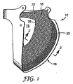
図1は、フレーム部材16および封鎖部材18を備えるフェイスシール12を示す。フレーム部材16は、薄い中実のプラスチックなどの非多孔質又は流体不透過性の材料から製造される。フレーム部材16は、フェイスシール12に構造的一体性を付与し、人の手の力又は圧力に応答してバイザ14(図4)上の位置にくるように手で操作できるように構成することができる。フレーム部材16は、手の圧力が取り除かれると、概ね元の構成に戻る。従って、フレーム部材16は、望ましくは可撓性がある、又は手で適合させることができると同時に、依然として、使用中、それが所望の封鎖構成を保持することを可能にするのに十分な構造的特性を示す。フレーム部材は、例えば、厚さ0.5〜1.5mmのプラスチック(ポリプロピレンなど)で製造されてもよい。フレーム部材は、望ましくは、使用者の視覚に干渉し得る反射を回避するため、少なくとも一方側に艶消し面を有する。一般に、プラスチックフレームは、厚さ約0.2mm〜0.5mmであってもよい。図1に示されているように、フレーム部材をバイザとは別々の部分として構成することができるか、又は、或いはバイザ本体に一体に製造することができる。用語を本文献中で使用する時、「一体」は、フレーム部材がバイザ本体と同時に製造され、図1に示されているフレーム部材16のように別々に製造される又は後でバイザに接合される部品ではないことを意味する。一体型のフレーム部材は、目立たないようにバイザ本体と「同じ1つのもの」であるように構成されてもよく、又は、バイザ本体から一体に延びる突出するフランジ又はリッジとすることができる。フェイスシールを容易に交換できるように、非一体型のフレーム部材が好ましい。
FIG. 1 shows a
図1は、更に、封鎖部材18がフレーム部材から半径方向内側に延び、それが、人の顔面の入る開口部19を有することを示す。開口部19は封鎖部材18の周縁部26によって画定され、周縁部26は好ましくは延伸可能であり、好ましくは、フェイスシールが様々なサイズの顔面にぴったりとフィットすることを可能にするように、着用者の顔面より小さくなるようなサイズに作られている。封鎖部材18は、延伸された後、元の構成に戻ることができるように、且つ、様々なサイズの顔面にフィットすることができるように、弾性を有する布帛から製造されてもよい。このようにして、延伸性又は弾性があると、送気ヘルメット装着時に布帛は多くの人の顔と十分に接触することができる。
FIG. 1 further shows that the sealing
呼吸ゾーンに入る空気を環境中に排出し、空気供給源から呼吸ゾーンに圧入される新しい清浄空気に取り替えることができるように、内部ガス空間内の過剰の流体が比較的制限されずに通過し得るように、布帛は少なくとも幾つかの部位が多孔質であってもよい。送気システムでは、内部ガス空間内の空気圧は、一般に、外部ガス空間の空気圧より大きい。この増大した圧力によって、空気は内部ガス空間から圧出される。内部ガス空間に清浄空気を連続的に強制的に流入させると圧力が増大する。空気流は、布帛中に存在し得る孔を通って内部ガス空間から出ることができる。 Excess fluid in the internal gas space passes relatively unrestricted so that air entering the breathing zone can be exhausted into the environment and replaced with fresh clean air that is forced into the breathing zone from an air source. As obtained, the fabric may be porous at least at some sites. In an air delivery system, the air pressure in the internal gas space is generally greater than the air pressure in the external gas space. This increased pressure forces air out of the internal gas space. When clean air is forced to continuously flow into the internal gas space, the pressure increases. Airflow can exit the internal gas space through holes that may be present in the fabric.
着用者の快適さを改善するため、着用者の顔面と接触するときに感触のよいニットから多孔質布帛を製造することができる。編布は、一般に、本来的に又は全体的に多孔質であり、このため空気は比較的粗い織目を通って内部ガス空間から逃げることができる。織物の中に一連の絡み合った又は絡み合うループが作り出されるように1つ以上のヤーンを織ることによってニットが得られる。編布は、ヤーンに対して約90°で又は垂直に走るヤーンの上下にヤーンが延びる純粋な織布とは区別される。編布は、一般に、1つ以上のヤーンの一連の絡み合うループを含むか又は本質的にそれらからなり、ニットは、一貫して垂直なパターンで出来るわけではない。この構成によって、純粋な織布より本来的に柔軟性のある編物は、フェイスシールに使用されるとき、顔面への快適さとフィットを助ける特徴になり得る。 In order to improve the wearer's comfort, the porous fabric can be made from a knit that feels good when in contact with the wearer's face. The knitted fabric is generally inherently or entirely porous so that air can escape from the internal gas space through a relatively coarse texture. A knit is obtained by weaving one or more yarns to create a series of intertwined or intertwined loops in the fabric. A knitted fabric is distinguished from a pure woven fabric in which the yarn extends above and below the yarn running at about 90 ° or perpendicular to the yarn. A knitted fabric generally comprises or consists essentially of a series of one or more yarns of intertwined loops, and the knit cannot be made in a consistent vertical pattern. With this configuration, a knitted fabric that is inherently more flexible than a pure woven fabric can be a feature that aids in comfort and fit to the face when used in a face seal.
封鎖部材の編成される部分は、例えば、弾性ヤーン、難燃性ヤーン、およびコンフォートヤーンのブレンドを含んでもよい。弾性ヤーンは、布帛の「延伸性」を改善するのに使用され、難燃性ヤーンは封鎖部材が過度の熱により燃焼又は劣化しないようにする機能をし、コンフォートヤーンは人の顔面に当たる封鎖部材の「感触」を改善する。また、これらのヤーンの糸を組み合わせて、同一のヤーン中に難燃性および快適さなどのこれらの特性の組み合わせを有するヤーンを製造してもよい。前述のように、延伸性特徴によって、封鎖部材が様々なサイズの顔面にぴったりとフィットすることが可能になる。弾性ヤーンは、主にポリウレタンなどのポリマーから製造されてもよく、又は、例えば、変性アクリル、ラテックス、又はこれらの組み合わせであってもよい。市販の製品としては、ライクラ(Lycra)(商標)(デラウェア州ウィルミントン(Wilmington, Delaware)のデュポン社(DuPont Corporation)から入手可能)、およびスパンデックス(Spandex)(商標)(カンザス州ウィチタ(Wichita, Kansas)のインビスタ社(Invista Inc)から入手可能)が挙げられる。難燃性特徴は、フェイスシールが火花又は高温の溶融金属の滴と接触し得る溶接および研削などの用途に重要である。難燃性ヤーンは、本来的に難燃性の材料から製造されてもよく、又は、布帛に難燃性を付与するため、例えば、化学的に処理されてもよい。より良好な洗濯耐久性を有し得るため、一般に本来的に難燃性の材料が好ましい。難燃性ヤーンの例としては、酸化された熱安定化ポリアクリロニトリル(polycarylonitriles)、難燃性ポリエステル、および幾つかのナイロンが挙げられる。市販の製品としては、パノックス(Panox)(商標)(英国クレックヒートン(Cleckheaton, UK)のランター・ユニバーサル・カーボン・ファイバーズ(Lantor Universal Carbon Fibres)から入手可能)、ノーメックス(Nomex)(商標)(デュポン社(DuPont Corporation)から入手可能)、およびトレビラ(Trevira)(商標)(ドイツ、ボビンゲン(Bobingen, Germany)のトレビラ社(Trevira GmbH)から入手可能)が挙げられる。コンフォートヤーンは、手触りの柔軟な感触を布帛に付与することを助け、このようにして布帛を人の顔面に接触するときに快適なものにする。本発明のフェイスシールに使用され得るコンフォートヤーンの一例は綿である。他の好適なコンフォートヤーンとしては、ポリエステル、アクリル、レーヨン、およびウールが挙げられる。弾性ヤーン、難燃性ヤーン、およびコンフォートヤーンは、一般に、布帛の重量を基準にして、それぞれ約0〜20%、30〜100%、および0〜70%で布帛中に使用され得る。好ましくは、弾性ヤーン、難燃性ヤーン、およびコンフォートヤーンは、それぞれ約1〜10%、35〜70%、および30〜60%で使用される。 The knitted portion of the sealing member may include, for example, a blend of elastic yarns, flame retardant yarns, and comfort yarns. Elastic yarns are used to improve the “stretchability” of a fabric, flame retardant yarns serve to prevent the sealing member from burning or degrading due to excessive heat, and comfort yarns are sealing members that strike a human face. Improve the “feel” of These yarn yarns may also be combined to produce a yarn having a combination of these properties such as flame retardancy and comfort in the same yarn. As mentioned above, the stretch characteristics allow the sealing member to fit snugly on various sized faces. The elastic yarn may be made primarily from a polymer such as polyurethane, or may be, for example, modified acrylic, latex, or a combination thereof. Commercially available products include Lycra ™ (available from DuPont Corporation, Wilmington, Del.), And Spandex ™ (Wichita, Kansas). Kansas) available from Invista Inc.). The flame retardant characteristics are important for applications such as welding and grinding where the face seal can come into contact with sparks or hot molten metal drops. The flame retardant yarn may be manufactured from an inherently flame retardant material or may be chemically treated, for example, to impart flame resistance to the fabric. In general, flame retardant materials are preferred because they can have better washing durability. Examples of flame retardant yarns include oxidized heat stabilized polyacrylonitriles, flame retardant polyesters, and some nylons. Commercially available products include Panox ™ (available from Lantor Universal Carbon Fibers, Cleckheaton, UK), Nomex ™ (Available from DuPont Corporation), and Trevira ™ (available from Trevira GmbH, Bobingen, Germany). The comfort yarn helps impart a soft feel to the fabric, thus making the fabric comfortable when touching the human face. One example of a comfort yarn that can be used in the face seal of the present invention is cotton. Other suitable comfort yarns include polyester, acrylic, rayon, and wool. Elastic yarns, flame retardant yarns, and comfort yarns may generally be used in the fabric at about 0-20%, 30-100%, and 0-70%, respectively, based on the weight of the fabric. Preferably, elastic, flame retardant, and comfort yarns are used at about 1-10%, 35-70%, and 30-60%, respectively.
布帛は、更に、本質的にどのような色であってもよく、ポリエステル、変性アクリル、若しくはこれらの材料の混合物若しくはブレンドなどの染色されたポリマー材料、又は綿などの染色された天然ヤーンを有する糸から製造することができる。ヤーン直径に関して、布帛は、50番手のシングルヤーン(single 1/50(fifties) count yarn)又は約70〜10番手、好ましくは60〜30番手のヤーン(70番手は10番手より細い)を有し得るが、他の太さが好適に使用されることがある。布帛(折り重ねられていない組み合わせ、即ち、1層の編物)は、厚さ約0.3〜3ミリメートル(mm)、好ましくは厚さ0.7〜1.5mmとすることができるが、フェイスシールが十分な流体流を可能にする場合、これより大きい又は小さい厚さも使用できる。編成されるフェイスシールは、1〜10のヤーン編糸、好ましくは約1〜5のヤーン編糸から製造されてもよい。ヤーン編糸の数は、一緒に編成されるヤーン糸の数に関係する。編布は、約1gg〜20gg、より好ましくは12gg〜18ggがあるように製造されてもよい。表記「gg」は、1インチ当たりのループの数に関係する。16ggの機械では、編み機に1インチ当たり16本の針がある。重要なことは、フェイスシールが装着するのに快適であり、排出される空気が内部ガス空間から迅速にパージされ得ることである。 The fabric may further be essentially any color, having dyed polymeric materials such as polyester, modified acrylic, or mixtures or blends of these materials, or dyed natural yarns such as cotton. Can be made from yarn. With respect to yarn diameter, the fabric has a 50th single yarn (single 1/50 (fifties) count yarn) or about 70-10th yarn, preferably 60-30th yarn (70th is thinner than 10th). Although other thicknesses may be suitably used. The fabric (unfolded combination, i.e. one layer of knitted fabric) can have a thickness of about 0.3 to 3 millimeters (mm), preferably 0.7 to 1.5 mm. Larger or smaller thicknesses can be used if the seal allows sufficient fluid flow. The knitted face seal may be made from 1 to 10 yarn yarns, preferably from about 1 to 5 yarn yarns. The number of yarn knitting yarns is related to the number of yarn yarns knitted together. The knitted fabric may be manufactured to have about 1 gg to 20 gg, more preferably 12 gg to 18 gg. The notation “gg” relates to the number of loops per inch. On a 16 gg machine, the knitting machine has 16 needles per inch. Importantly, the face seal is comfortable to wear and the exhausted air can be quickly purged from the internal gas space.
編物は、約15%のライクラ(Lycra)(商標)弾性ヤーンおよび約85%のノーテックス(Notex)(商標)ヤーン(本来的に難燃性のヤーン)を含んでもよい。ライクラ(Lycra)(商標)は、本来的に伸びやすい編成されたノーテックス(Notex)(商標)に弾性を加え、そのためフェイスシールに追加の弾性材料の必要がない。或いは、編成された材料は、重量を基準にして約0〜20%の弾性ヤーン、45〜55%のカネカロン(Kanecaron)(商標)ヤーン(日本、東京の株式会社カネカ(Kaneka Corporation, Tokyo, Japan)から入手可能な本来的に難燃性の変性アクリル系ヤーン)および約40〜60%の綿ヤーンを含んでもよい。例えば、エラストマーは変性アクリル、ラテックス、又はその組み合わせであってもよい。このような編成された材料を使用し、空気がヘルメットの呼吸ゾーン又は内部ガス空間を適切に出ることを可能にする、快適で呼吸に適したフェイスシールを達成することができる。編成された封鎖部材の更なる説明は、代理人整理番号60019US002で本特許出願と同日に出願された、「編成されたフェイスシールを有する送気ヘルメット(Supplied Air Helmet Having A Knitted Face Seal)」と題された、同時係属中の特許出願である米国特許出願第10/987,641号明細書に見られる。 The knitted fabric may include about 15% Lycra ™ elastic yarn and about 85% Notex ™ yarn (an inherently flame retardant yarn). Lycra (TM) adds elasticity to the knitted Notex (TM), which is inherently stretchable, so that no additional elastic material is required for the face seal. Alternatively, the knitted material is about 0-20% elastic yarn, 45-55% Kanecaron (TM) yarn (Kaneka Corporation, Tokyo, Japan, Japan, based on weight) ) And inherently flame retardant modified acrylic yarns) and about 40-60% cotton yarns. For example, the elastomer may be modified acrylic, latex, or a combination thereof. Such a knitted material can be used to achieve a comfortable and breathable face seal that allows air to properly exit the breathing zone or internal gas space of the helmet. A further description of the knitted sealing member is "Supplied Air Helmet Haven A Knitted Face Seal", filed on the same day as this patent application with agent number 60019US002. No. 10 / 987,641, which is a co-pending patent application entitled US Pat. No. 10 / 987,641.
図1に示されているように、フェイスシール12は、それぞれ第1および第2の透過性ゾーン20および22を有してもよい。内部ガス空間から出る空気が第2の透過性ゾーン22を通って運ばれる方が容易であるように、第1の透過性ゾーン20の方が空気流に対する抵抗が大きくてもよい。図1に示されている実施形態では、ゾーン22の多くは、着用者の顔面の前頭および側部に密接するように押し当てられ、このようにして流体がそれらの位置で内部ガス空間から出ることが防止される。しかし、顎の下では、流体をより迅速にマスク内部からパージすることができる。前述のように、このような差異のある透過性を有することの利点は、それによって流体がバイザのレンズ69(図4および図5)の内側を横切って流動することが可能になり、それによって流れが着用者の顔面の前および顎の下に導かれ、着用者を涼しく保ち、汚染した逆流が内部ガス空間に入ることを防止するのに役立つことである。
As shown in FIG. 1, the
図2は、フレーム部材16がどのようにして角度αを決定するように構成されるかを示す側面図である。フレーム部材16は、90°未満、好ましくは約50〜80°の挟角αを決定する眉弓部分21と顎部分23を有する。このような角度αを有するフレーム部材16を使用すると、汚染物質が内部ガス空間に入ることが防止されるように、良好なフィットを得ることができる。
FIG. 2 is a side view showing how the
図3は、封鎖部材18をどのようにしてフレーム部材16に固定できるかを示す。これは、例えば、編成された封鎖部材18をフレーム部材16の位置24に縫い付けることによって達成されてもよい。布帛18をフレーム部材16に固定するのに役立つように、弾性材料25のストリップを使用してもよい。布帛は一般に多孔質であるため、弾性材料25は、フレーム部材に縫い付けられるとき、縫製用のヤーンが布帛を引裂することを防止する役割をする。更に、布帛18は、好ましくは編成されており、弾性の品質を有し、延伸された又は延ばされた状態でフレーム部材に付けられている。フレーム部材16をこのようにして固定すると、布帛18がピンと張った状態でそこに存在することが可能になる。このように予め延伸された状態又はピンと張った状態であるため、布帛18が、着用者の顔面に、特に内側周縁部26付近の領域でぴったりと係合することが可能になる。布帛18は、予め延伸された状態でフレーム部材に配置されてもよいが、必ずしも100%延伸される必要はなく(典型的には、その完全に延伸された状態の約40〜90%で取り付けられる)、従って、更に延伸又は拡張されて、様々なサイズの顔面にぴったりと係合する、又は様々なサイズの顔面を入れることができる。縫い付けの他に、リベット締め、ねじ留め、および接着等の他の機械的又は物理的方法を使用して、編布をフレーム部材16に固定してもよい。
FIG. 3 shows how the sealing
図3に示されているように、封鎖部材18は、好ましくは、折り重ねられて内周26を画定する。内周26に沿って折り重ねた端部又は縁部を使用すると、さもなければ存在し得る粗い又はより突出した縁部がなくなるか又は低減することによって、着用者の快適さが更に改善され得る。シール部材の周囲26が着用者の顔面と主に接触する折り目を有する編布が、特に快適であることが分かった。折り重ねた縁部26を使用することによって、ほつれが生じる機会もさらに低減し得、その折り重ねた構成によって着用者の快適さも増大し得る。従って、折り目26は、人の顔に粗く接触し得る自由縁部又は直線的縁部がフェイスシールにないようにする。折り目26は、更に第1および第2の並置された層28および30を作り出す。二重層の封鎖部材18は、汚染物質が内部ガス空間に入るのを防止することを助け得る。層30は、フェイスシールド10装着時に、着用者のフェイスマスクと直接接触した状態にある。
As shown in FIG. 3, the sealing
図4は、フェイスシール12をどのようにしてバイザ14に固定できるかを示す。フェイスシール12のフレーム部材16は、第1および第2の側部分38および40を有する。これらの側部分38および40をバイザ14のそれぞれ第1の側部分と第2の側部分42と44の間に押し込むことができるように、側部分38および40を中心方向に内側に又は互いの方に押すことができる。前述のように、手の圧力に応答して適合し、その圧力が停止したとき元の構成に戻るようにフレーム部材16を構成することができる。従って、フレーム部材16は、より剛性のあるバイザ14内に摩擦配置され得るように可撓性又は適合性があってもよい。フレーム部材16は、側頭部の位置60および62でスペーサ要素48および50に当接するように作られている第1および第2の受け口44および46をそれぞれ有してもよい。受け口44および46が位置60および62でヒンジアセンブリに当接して並置されるように、フレーム部材16がバイザ14内に配置された後、フレーム部材16の前部分64がバイザ14の第3の係合点又は棚状部66に係合するまで、フレームアセンブリ16を反時計回りに回転させてもよい。フレーム部材16の前部分64が棚状部66上に並置されると、更なる回転運動が防止され、フェイスシール12はフェイスシールド14内に静止保持されたままになる。本発明の図面は、3つの摩擦係合点を示すが、必要に応じて又は望ましい場合、本発明では、他の係合点(例えば、4、5、6又はそれより多い)の使用が考えられる。或いは、当該技術分野で既知のように、ペッグ又は穴を使用して、フレームをシールドに取り付けてもよい。
FIG. 4 shows how the
ヘルメットバイザに摩擦係合できるフェイスシールの一例が、代理人整理番号60021US002で本願と同日に出願された、「摩擦係合される送気ヘルメットフェイスシール(Frictionally Engaged Supplied Air Helmet Face Seal)」と題された、米国特許出願第10/988,789号明細書に詳細に記載されている。このフェイスシールは、追加の固定装置なしで摩擦係合を使用することによってバイザに取り付けることができるという点で特に有益である。使用できる可能性のあるフェイスシールの別の例は、米国特許第6,016,805号明細書(バーンズ(Burns)ら)に示されている。 An example of a face seal that can be frictionally engaged with a helmet visor is entitled “Frictionally Energized Applied Helmet Face Face”, filed on the same day as this application under agent serial number 60021US002. US patent application Ser. No. 10 / 98,789, which is hereby incorporated by reference in its entirety. This face seal is particularly beneficial in that it can be attached to the visor by using frictional engagement without an additional locking device. Another example of a face seal that may be used is shown in US Pat. No. 6,016,805 (Burns et al.).
ヘルメット10を装着するため、着用者は冠部材68を頭蓋上に配置し、バイザ14を下向きに回転させ、それが着用者の顔面のすぐ前にくるようにする。このとき着用者は窓69を通して見ることができる。ヘルメットが溶接の目的に使用される場合、窓は、溶接工のトーチの光に応答して直ぐに暗色化する自動遮光レンズ(Auto−darkening lens)(ADL)とすることができる(例えば、ヘルネル(Hoernell)およびパーマー(Palmer)に付与された米国特許第6,097,451号明細書および米国特許第5,825,441号明細書を参照されたい)。次いで、着用者はタブ70を引っ張り、封鎖部材18の顎部分72を顎の下に引く。封鎖部材周囲26の残りの部分は、着用者の前頭および頬部位に密接するように引き寄せられる。このようにして、着用者の顔面、封鎖部材18、およびフェイスシールド又はバイザ14によって画定される呼吸ゾーン又は内部ガス空間が作り出される。
To wear the
前述のように、封鎖部材は、圧力がかかっているとき空気が内部ガス空間からパージされ得るように、全体的に多孔質であってもよい。好ましい編布が一般に多孔質であるにも関わらず、フェイスシール内に一般に存在する陽圧のため、汚染物質は内部ガス空間に入ることが防止される。操作中、電動空気供給源からの圧力で清浄空気を内部ガス空間に供給することができる。電動空気供給源を使用するとき、空気は、内部ガス空間に導かれる前に電力で又は強制的に空気フィルタを通される。これらのシステムは、一般に「電動ファン付き呼吸用保護具」又はPAPRと称される。空気フィルタは、着用者の腰の周りに装着されるベルト上に支持されるハウジングに収容されてもよい。これらの種類のデバイスの例は、米国特許第6,279,572B1号明細書、同第6,250,299B1号明細書、同第6,014,971号明細書、同第5,125,402号明細書、同第4,965,887号明細書、同第4,462,399号明細書、および同第4,280,491号明細書に示されている。空気を内部ガス空間に導くための送気システムに関して使用され得る送風機の例は、米国特許第6,575,165B1号明細書、および米国意匠特許第449,099S号明細書に示されている。呼吸ゾーンに入る空気流が安全レベルを下回るときを表示するため、送気ヘルメットに流量センサを使用してもよい−米国特許第6,615,828B1号明細書(ペザーブリッジ(Petherbridge))を参照されたい。更に、フィルタ要素の使用の記録を保存するため、フィルタ要素に不揮発性記憶装置を取り付けてもよい−米国特許第6,186,140B1号明細書(オーグ(Hogue))を参照されたい。 As mentioned above, the sealing member may be generally porous so that air can be purged from the internal gas space when pressure is applied. Despite the preferred knitted fabric being generally porous, contaminants are prevented from entering the internal gas space due to the positive pressure typically present in the face seal. During operation, clean air can be supplied to the internal gas space with pressure from an electric air supply source. When using a motorized air supply, the air is forced or forced through an air filter before being directed into the internal gas space. These systems are commonly referred to as “respirators with an electric fan” or PAPR. The air filter may be housed in a housing that is supported on a belt that is worn around the waist of the wearer. Examples of these types of devices are described in US Pat. Nos. 6,279,572 B1, 6,250,299 B1, 6,014,971, 5,125,402. No. 4,965,887, No. 4,462,399, and No. 4,280,491. Examples of blowers that can be used in connection with an air delivery system for directing air to an internal gas space are shown in US Pat. No. 6,575,165B1 and US Design Patent No. 449,099S. A flow sensor may be used in the insufflation helmet to indicate when the airflow entering the breathing zone is below a safe level-see US Pat. No. 6,615,828 B1 (Petherbridge). I want. In addition, a non-volatile storage device may be attached to the filter element to keep a record of the use of the filter element-see US Pat. No. 6,186,140 B1 (Hogue).
図5に示されているように、電動空気供給源と流体練通しているエアダクト74を介して空気を内部ガス空間の中に流してもよい。ダクト74は、入口ポート75と出口ポート77を有し、冠部材68によって支持されている。空気をヘルメットの内部ガス空間に導くのに使用され得るエアダクトは、更に、2004年4月7日に出願され、「エアダクト(Air Duct)」と題された米国特許出願第29/202,969号明細書、現、米国特許第 号明細書(ハインド(Hind)ら)に示されている。入口75は清浄空気源に接続され、出口77は封鎖部材18と着用者の前頭(図示せず)の間に配置されている。前述のように、空気流は、例えば、封鎖部材18(図1および図2)中に存在し得る孔を通り、内部ガス空間から出る。エアダクト74を冠部材68の2箇所に固定することができる。打ち抜かれたプラスチック部品73でエアダクト74の後部を冠部材68の後部から一定の距離に保持することができる。エアダクト74の前部を眉弓のところで冠部材68の前部に固定することができる。このようにして、エアダクト74が使用中に移動する又はぐらつくことを防止する。眉弓のところで、エアダクト74はフェイスシール12と冠部材68の間を通る。エラストマーのフェイスシール材料は、フェイスシールがエアダクトの周りに良好なシールを形成することを可能にする。入口を清浄空気源に接続することができ、出口をフェイスシールとバイザの間に配置することができる。着用者の頭部にフィットするように冠部材の周囲長を調節するため、ハーネスの後部に調節ノブを配置することができる。
As shown in FIG. 5, air may flow into the internal gas space via an
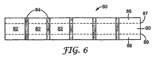
図6は、編成された材料の細長いストリップ80を示し、このストリップ80は、複数の編成された封鎖部材を形成するため、一連のブランクセグメント82を含む。各セグメント82は、分解性部分84によって分離されている。材料のストリップが連続的に編成された細長いシート80を形成するように、両方のセグメント82および84は一緒に編成されている。シート80は、全体にわたって均一なニットを有してもよいが、好ましくは、異なる弾性度を有するゾーンを含む。破線87および89の上下にぞれぞれ配置されているゾーン86および88は、好ましくは、織物中に弾性材料をほとんど又は全く有していない。ゾーン90は、ゾーン86および88よりも比較的多くの弾性材料を有する。様々な弾性ゾーンを有する編成された材料を使用すると、図1および図2を参照して前述したように、最終製品の構成に有益である。布帛の重量を基準にして、ゾーン86および88は好ましくは約0〜5%の弾性ヤーン、より好ましくは約0〜1%の弾性ヤーンを含有し、ゾーン90は約2〜10%の弾性ヤーン、より好ましくは約3〜7%の弾性ヤーンを含有する。
FIG. 6 shows an
本発明による編成されたフェイスシールを製造する際、編成された材料の細長いストリップ80を蒸気に暴露させ、離間配置されたゾーン84を分解してもよい。これらの分解性部分84は、主に水溶性の、又は「海草」由来の、又は人工のヤーン(スイスのエムス・ケミー社(EMS−Chimie AG)から入手可能なグリロン(Grilon)(商標)など)から製造されてもよい。十分な量の蒸気に暴露されると、水溶性ヤーンは分解し、細長いシート80は一連のブランク82を形成する。
In producing a knitted face seal according to the present invention, an
図7は、形成されたブランク82の1つを示す。図示されているように、セグメント82は、「くびれている」。中心ゾーン90に、より多くの弾性があるため、このくびれ効果が生じる。シート材料80(図6)を蒸気に暴露させてセグメント82(図6)を分離させるとき、弾性材料は硬化して「一箇所に集まり」、セグメント82をくびれさせる。
FIG. 7 shows one of the
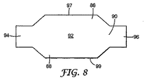
くびれているセグメント82をそれぞれ図8に示されている形状に切断する。切断された各セグメントは、対向するタブ94および96を有する。これらのタブを縫い合わせてチューブを形成する。次いで、チューブの対向する端部97および99を一緒に接合し、図3に示されているようにフェイスシール10のフレーム部材16に縫い付ける。従って、弾性ゾーン90は、封鎖部材18の周端26の方にある(図1および図3)。従って、材料86および88のゾーンによって画定される非弾性ゾーン20は、図3に数字24で記載されているフェイスシールの固定される部分により近いところに配置される。部分86および88は部分90より弾性が小さい材料を含有し得るだけでなく、部分86および88は、より緻密な織目も含み得、図1および図3に示されているゾーン20の空隙率、およびゾーン22より著しく小さい空気透過性を有する。従って、ゾーン22はゾーン20より多孔質であり、より低い通気抵抗(pressure drop)を有する。ゾーン22は、従って、送気ヘルメットの内部ガス空間から排出される空気のために最も抵抗の小さい通路を形成する。全体としてフェイスシール全体の通気抵抗は、典型的には、約10〜200パスカル、より典型的には、約20〜110パスカルである。高透過性ゾーン22の通気抵抗は、好ましくは約10〜100パスカル、より好ましくは約20〜70パスカルである。低透過性ゾーン20の通気抵抗は、その全体で、好ましくは約90〜200パスカル、より好ましくは約120〜180パスカルである。1対のエアチャックを使用し、直径60ミリメートルの穴の上にフェイスシールをクランプすることによって、通気抵抗を測定することができる。マノメータで、毎分85リットルの流量を使用して、フェイスシールの各側の圧力を測定する。フェイスシールの材料全体の空気流量は、典型的には約5〜200cm3/s/cm2、より典型的には約20〜150cm3/s/cm2である。高透過性ゾーン22の空気流量は、好ましくは85〜200cm3/s/cm2、より好ましくは約100〜150cm3/s/cm2である。低透過性ゾーン20の空気流量は、その全体で、好ましくは約5〜80cm3/s/cm2、より好ましくは約20〜70cm3/s/cm2である。ASTM D737−96に記載の試験方法、テキスタイル布帛の空気透過性の標準試験方法(Standard Test Method for Air Permeability of Textile Fabrics)を使用して、空気流量を測定することができる。
Each
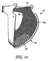
図10は、フェイスシール12の別の実施形態を示す。前記の図に示されている実施形態と同様に、フェイスシール12はフレーム部材16および封鎖部材18を含む。封鎖部材18は、第1および第2の透過性ゾーン20’〜22’を有する。ゾーン22’はゾーン22より透過性が大きく、主に着用者の顎部位に配置される。内部ガス空間内に配置されている陽圧空気は、主に、ゾーン22’を通って内部ガス空間から出る。空気はまた、ゾーン20’を通って封鎖部材18から出ることもできるが、図10に示されているフェイスシールを有する送気ヘルメット装着時、空気は概ね使用者の顎部位の方に導かれる。
FIG. 10 shows another embodiment of the
本発明では、出口ポート77(図5)から出て着用者の顔面を横切る、制御された空気流が達成され得る。出口ポート77(図5)から呼吸ゾーンに入る清浄空気は、主に、より多孔質のゾーン22、22’(図1、図3および図10)を通って内部ガス空間から出る。内部ガス空間内の増大した圧力のため、汚染物質が送気ヘルメットの呼吸ゾーンに入ることは更に困難である。空気が主に内部ガス空間から圧出される領域である封鎖部材のゾーン22、22’は、汚染物質がその内部ガス空間に偶発的に流入することを防止するのを助ける。内部ガス空間内に存在する圧力の方が高いため、空気は、ゾーン22、22’に存在する孔から圧出される。従って、差異のある透過性又は異なる空気流量を有する封鎖部材を提供すると、空気が着用者の顔面又は呼吸ゾーンを横切って吹き流れると同時に、汚染物質が内部ガス空間に偶発的に流入するのを防止することが可能になる。
In the present invention, a controlled air flow out of the exit port 77 (FIG. 5) and across the wearer's face can be achieved. The clean air entering the breathing zone from the outlet port 77 (FIG. 5) exits the internal gas space primarily through the more
差異のある透過性を有するフェイスシールを提供するために密度の異なるニットを有するフェイスシールを使用することの代替として、例えば、封鎖部材の透過性が望ましくない領域に非多孔質プラスチック層をコーティングすることも可能である。或いは、図3に示されているように、非多孔質シートをフェイスシールの、例えば、層28と30の間に固定することができる。更に、空気が膜を通って拡散することを可能にするが汚染物質の流入を防止する微孔質膜を使用することが可能である。 As an alternative to using a face seal with a knit of different density to provide a face seal with different permeability, for example, coating a non-porous plastic layer in areas where the permeability of the sealing member is undesirable It is also possible. Alternatively, as shown in FIG. 3, a non-porous sheet can be secured between the face seals, eg, layers 28 and 30. In addition, it is possible to use a microporous membrane that allows air to diffuse through the membrane but prevents the inflow of contaminants.
前述の電動空気システムの他に、本発明は、清浄空気を人に供給するために、典型的には圧力下にある、空気又は酸素のタンクを有する自蔵式呼吸装置(SCBA)などの圧縮空気システムと共に使用することもできる。SCBAシステムの例は、次の米国特許第6,478,025号明細書、同第4,886,056号明細書、同第4,586,500号明細書、および同第4,437,460号明細書に示されている。本発明を解釈する目的で、圧縮空気システムは送気システムであると考えられる。更に、本発明の送気システムは、溶接用ヘルメット又は溶接環境と共に使用され得るだけではなく、例えば、手術環境又はクリーンルーム用に作られたヘルメットにも使用され得る−例えば、米国特許第4,901,716号明細書、同第4,055,173号明細書、同第4,019,508号明細書、および同第3,955,570号明細書を参照されたい。 In addition to the motorized air system described above, the present invention provides a compression, such as a self-contained breathing apparatus (SCBA) having a tank of air or oxygen, typically under pressure, to supply clean air to a person. It can also be used with an air system. Examples of SCBA systems include the following US Pat. Nos. 6,478,025, 4,886,056, 4,586,500, and 4,437,460. It is shown in the specification of the issue. For purposes of interpreting the present invention, the compressed air system is considered to be an air delivery system. In addition, the air delivery system of the present invention can be used not only with a welding helmet or welding environment, but can also be used with, for example, a surgical environment or a helmet made for a clean room—eg, US Pat. No. 4,716, U.S. Pat. No. 4,055,173, U.S. Pat. No. 4,019,508, and U.S. Pat. No. 3,955,570.
次の実施例は、本発明の特徴、利点、および他の詳細を更に説明するために選択されたに過ぎない。しかし、実施例はこの目的にかなうが、使用される特定の成分および量、並びに他の状態および詳細は、本発明の範囲を必要以上に限定するように解釈されるべきではないことを明確に理解されたい。 The following examples have been selected merely to further illustrate features, advantages, and other details of the invention. However, while the examples serve this purpose, it is clearly understood that the specific ingredients and amounts used, as well as other conditions and details, should not be construed to unduly limit the scope of the invention. I want you to understand.
所望の形状および構成を達成するように切断され縫製された直線的1&1リブ編みブランクからフェイスシールの封鎖部材を製造した。難燃性/コンフォートヤーンの組み合わせ、弾性ヤーン、および水溶性ヤーンの3つのヤーンからブランクを製造した。難燃性/コンフォートヤーンの組み合わせは、カネカロン(Kanecaron)(商標)繊維、プロテックス(Protex)−M(日本の株式会社カネカ(Kaneka Corporation, Japan)から入手可能な変性アクリル系繊維)および綿繊維を含有した。互いに対して、カネカロン(Kanecaron)(商標)繊維を55重量%使用し、綿繊維を45重量%使用した。エラストマーヤーンは、200デシテックスであり、エラスタン、ライクラ(Lycra)(商標)および捲縮ナイロンをそれぞれ62重量%および38重量%含有した。これらの2つのヤーンは編成されたブランク中の主構造要素として機能した。難燃性/綿ヤーンの組み合わせおよび弾性ヤーンを両方とも青色に染色した。難燃性/コンフォートヤーンも同様にワックス処理した(waxed)。ブランク中の弾性ヤーンの含量は、ブランクの長さに沿って変化し、ブランクの中心はヤーンの量がもっとも多く、ブランクの最上部および最下部には弾性ヤーンがないように減少した。一連のブランクを連続的に製造できるように、一列の水溶性ヤーン(グリロン(Grilon)(商標)、スイス、エムス・ケミー社(EMS−Chimie AG,Switzerland))を各ブランクの端部で編成した。使用中620本の針を有した16gg(1インチ当たり針16本又は針6.3本/cm)のパワーフラットマシン(power flat machine)で連続布帛を編成した。蒸気処理されるとき、水溶性ヤーンは溶解し、連続的長さの編地から個々のブランクを形成した。ブランクは徐々に変化する5つの領域を含んでいた。 Face seal sealing members were made from linear 1 & 1 ribbed blanks cut and sewn to achieve the desired shape and configuration. Blanks were made from three yarns: a flame retardant / comfort yarn combination, an elastic yarn, and a water soluble yarn. The flame retardant / comfort yarn combination comprises Kanecaron (TM) fiber, Protex-M (modified acrylic fiber available from Kaneka Corporation, Japan) and cotton fiber. Contained. For each other, 55% by weight Kanecaron ™ fiber and 45% cotton fiber were used. The elastomeric yarn was 200 dtex and contained 62% and 38% by weight of elastane, Lycra ™ and crimped nylon, respectively. These two yarns functioned as the main structural element in the knitted blank. Both the flame retardant / cotton yarn combination and the elastic yarn were dyed blue. The flame retardant / comfort yarn was similarly waxed. The content of elastic yarn in the blank varied along the length of the blank, with the center of the blank decreasing with the highest amount of yarn and no elastic yarn at the top and bottom of the blank. A row of water-soluble yarns (Grilon ™, EMS-Chimie AG, Switzerland) was knitted at the end of each blank so that a series of blanks could be produced continuously. . In continuous use, a continuous fabric was knitted on a 16 gg (16 needles per inch or 6.3 needles / cm) power flat machine with 620 needles in use. When steamed, the water soluble yarns dissolved and formed individual blanks from continuous lengths of knitted fabric. The blank contained five regions that changed gradually.
領域1は、余分のヤーン編糸を有し、清浄空気が頭頂部から排出され得るように設計されたより剛性のあるニットであった。これは、カネカロン(Kanecaron)(商標)/綿ヤーンの3つの編糸を含み、24サイクル、48列を有した。領域2は、排出領域1とフェイスシール領域3の間の移行領域であった。これは、50番手ヤーンの2つの編糸、および、タックされるライクラ(Lycra)(商標)ヤーン(4列毎に1つ使用)を含む48列を含んだ。領域3は、顔面接触領域であり、皮膚に快適であるように設計された。領域3は、50番手ヤーンの2つの編糸を含み、11サイクル、88列を有し、2列ごとに1つライクラ(Lycra)(商標)ヤーンでタックされた。領域4は、顔面接触領域と排出領域の間の移行領域であり、領域2と同じ構造を有した。領域5も排出領域であり、領域1と同じ構造を有した。
ブランクの中心付近で弾性ヤーンのパーセンテージがより大きく、ブランクの中心まで縁部を追うと、ブランクの側縁部はテーパ状であった又は「くびれていた」。本発明のフェイスシールを形成するため、タイプ301の本縫いを使用してブランクの縁部を縫い合わせ、円筒を形成した。次いで、タイプ514の4本糸のかがり縫いを加え、2つの開放端の縁部を縫い合わせることができるように円筒を折り重ねた。また、プレスで打抜いた厚さ1mmの黒色ポリプロピレンプラスチックであった支持プラスチックフレームに、これらの縁部を縫い付けた。1センチメートル当たり3〜4の縫い目を有するタイプ301の本縫いミシンを使用し、編成された材料を固定した。最後に、皮のタブを編成された材料に縫い付けた。次いで、得られたフェイスシールを空気流解析に使用した。 The percentage of elastic yarn was greater near the center of the blank and the side edges of the blank were tapered or “constricted” as the edge was traced to the center of the blank. In order to form the face seal of the present invention, a type 301 lock stitch was used to sew the blank edges together to form a cylinder. Next, a type 514 four-thread overlock was added, and the cylinder was folded over so that the edges of the two open ends could be stitched together. Further, these edges were sewn to a supporting plastic frame which was a black polypropylene plastic having a thickness of 1 mm punched out by a press. A type 301 lockstitch sewing machine with 3-4 seams per centimeter was used to secure the knitted material. Finally, the leather tabs were sewn into the knitted material. The resulting face seal was then used for air flow analysis.
シールがヘルメットに固定されている時のシール材料の延ばされた構成又は延伸構成を反映するように、フェイスシール標的領域で空気流解析を行った。流れの望ましさ(高又は低)のゾーンをマッピングすることによって標的領域を選択した。まず、ヘルメットに固定されている時にシールの標的領域に直径1インチの円をマーキングすることによって、フェイスシールの延伸された構成を試験固定具に平行移動させた。次いで、フェイスシールをヘルメットから取り外し、標的領域の材料がヘルメットに取り付けられている時と同じ構成に延伸されるように、試験装置に固定した。1インチ流動オリフィスを使用し、ASTM D737−96、テキスタイル布帛の空気透過性の標準試験方法(Standard Test Method for Air Permeability of Textile Fabrics)に記載の試験方法でシール材料の試験を行った。 Air flow analysis was performed at the face seal target area to reflect the extended or stretched configuration of the seal material when the seal was secured to the helmet. Target areas were selected by mapping zones of flow desirability (high or low). First, the stretched configuration of the face seal was translated to the test fixture by marking a 1 inch diameter circle in the target area of the seal when secured to the helmet. The face seal was then removed from the helmet and secured to the test apparatus so that the target area material was stretched to the same configuration as when attached to the helmet. Seal materials were tested using the test method described in ASTM D737-96, Standard Test Method for Air Permeability of Textile Fabrics, using a 1 inch flow orifice.
フェイスシールの空気流評価の標的領域を流動点又は位置A〜Eにマッピングした。これらの位置は、望ましくは高い又は低い空気流特性を有するフェイスシール上の部位を表した。ヘルメットに送達される空気をフェイスシールのある一定の部分を優先的に通して導き、ヘルメットの呼吸ゾーンに流すのに役立つと同時に、有害な可能性のあるガスが内側に侵入することを防止するように空気流マップを設計した。 The target area of the face seal airflow assessment was mapped to pour points or locations A-E. These locations represented sites on the face seal that desirably have high or low air flow characteristics. Directs the air delivered to the helmet preferentially through certain parts of the face seal, helping to flow into the breathing zone of the helmet, while preventing the entry of potentially harmful gases inside The air flow map was designed as follows.
流動位置が一般に、シールをヘルメット/シールアセンブリに配置した状態で生じるため、極座標を使用して流動位置の中心位置を決定した。座標系の原点と流動部位の中心との間で決定される位置線の向きおよび長さを使用して、流動点を位置決めした。図9に指示子「O」を使用して示されるように、座標系の原点は、実施例のヘルメットに関する3つの基準軸の交点によって決定される点に位置決めされた。基準線YY1はヘルメット開口部を左右に二等分し、基準線XX1は線YY1に垂直であり、ヘルメット開口部を前後におおよそ二等分した。基準線XX1は、更に線ZZ1と交差した。線ZZ1は、フェイスシールがヘルメットに配置されている時、フェイスシールの開口部の中心を通った。基準線YY1およびXX1は、ヘルメットの底部開口部を画定する平面上にあり、基準線ZZ1は両方の線YY1およびXX1に垂直であった。 Since the flow position generally occurs with the seal placed in the helmet / seal assembly, polar coordinates were used to determine the center position of the flow position. The pour point was positioned using the orientation and length of the position line determined between the origin of the coordinate system and the center of the flow site. As shown in FIG. 9 using the indicator “O”, the origin of the coordinate system was positioned at a point determined by the intersection of the three reference axes for the example helmet. The reference line YY 1 bisected the helmet opening to the left and right, the reference line XX 1 was perpendicular to the line YY 1 , and the helmet opening was roughly bisected back and forth. The reference line XX 1 further intersected with the line ZZ 1 . Line ZZ 1 passed through the center of the face seal opening when the face seal was placed on the helmet. Reference lines YY 1 and XX 1 were on a plane that defined the bottom opening of the helmet, and reference line ZZ 1 was perpendicular to both lines YY 1 and XX 1 .
位置線の向きを極座標角度θおよびφで表示した。角度θは、位置決め線と線OYの向きを決定し、「O」は原点であった。角度φは、位置決め線と線OZの向きを決定した。着用者の顎を位置決めし得るθ決定角度は0°の範囲であり、着用者の頭部の側部に対する位置を位置決めするθ決定角度は90°に近かった。110°に近いφ決定角度は、フェイスシールの顎領域の位置を与え、160°に近いφ決定角度は、フェイスシールの前頭に接触する領域の概略の位置を与えた。位置線の長さεは、原点から流動ゾーンの中心までの線の長さである。実施例で評価されるヘルメットでは、ヘルメットの前部から線XX1までの距離は15センチメートルであり、ヘルメットの側部から線YY1までの距離は11センチメートルであった。 The direction of the position line is indicated by polar coordinate angles θ and φ. The angle θ determines the orientation of the positioning line and the line OY, and “O” is the origin. The angle φ determined the orientation of the positioning line and the line OZ. The θ determination angle at which the wearer's jaw can be positioned was in the range of 0 °, and the θ determination angle for positioning the position relative to the side of the wearer's head was close to 90 °. A φ determination angle close to 110 ° gave the position of the jaw region of the face seal, and a φ determination angle close to 160 ° gave an approximate position of the region in contact with the frontal face of the face seal. The length ε of the position line is the length of the line from the origin to the center of the flow zone. The helmet is evaluated in Example, the distance from the front of the helmet to the line XX 1 is 15 centimeters, the distance from the side of the helmet to the line YY 1 was 11 centimeters.
空気流マップおよび空気流の値を表1に記載する: Airflow maps and airflow values are listed in Table 1:

表1に見られるように、フェイスシールの特定の流動ゾーンに対して空気流マップを設計することができる。フェイスシールを通る空気流をこのようにしてマッピングすることにより、ヘルメットに送達される流量を最適に使用して保護システムをパージすると同時に、有害なガスの流入に対する十分な抵抗を維持することができる。 As can be seen in Table 1, an air flow map can be designed for a particular flow zone of the face seal. By mapping the air flow through the face seal in this way, the flow delivered to the helmet can be optimally used to purge the protection system while maintaining sufficient resistance to harmful gas inflows. .
本発明は、本発明の趣旨および範囲から逸脱することなく、様々な変更および変形を取り得る。従って、本発明は、前述に限定されるものではなく、冒頭の特許請求の範囲に記載される限定およびそのあらゆる等価物によって規定されることを理解されたい。 Various changes and modifications can be made to the present invention without departing from the spirit and scope of the invention. Accordingly, it is to be understood that the invention is not limited to the foregoing, but is defined by the limitations set forth in the following claims and any equivalents thereof.
また、本発明は、本明細書に具体的に開示されていない要素がなくても好適に実施され得ることを理解されたい。 In addition, it should be understood that the present invention can be suitably implemented without any elements that are not specifically disclosed herein.
背景技術のセクションのものを含む前述の全ての特許および特許出願は、全て、参照により本明細書に援用される。 All the aforementioned patents and patent applications, including those in the background section, are all incorporated herein by reference.
Claims (18)
(b)前記バイザに固定され、封鎖部材およびフレーム部材を含むフェイスシールであって、前記封鎖部材が前記フレーム部材から半径方向内側に延び、前記封鎖部材が少なくとも第1および第2の透過性ゾーンを有し、前記第2のゾーンの方が前記第1のゾーンより透過性が大きいフェイスシールと、
を備える、送気ヘルメット。 (A) a visor;
(B) a face seal fixed to the visor and including a sealing member and a frame member, the sealing member extending radially inward from the frame member, wherein the sealing member is at least a first and a second permeable zone A face seal in which the second zone is more permeable than the first zone;
An air-feeding helmet.
(b)前記バイザに固定され、そこから延びる封鎖部材を含むフェイスシールであって、前記封鎖部材が第1および第2の透過性ゾーンを有する布帛を含み、前記第2のゾーンの方が前記第1のゾーンより透過性が大きく、前記布帛が前記封鎖部材の内周を画定する折り重ねた縁部を有し、前記第2のゾーンの流量が約85〜200cm3/s/cm2であり、前記第1のゾーンの流量が約5〜80cm3/s/cm2である、フェイスシールと、
を備える、送気ヘルメット。 (A) a visor;
(B) a face seal including a sealing member secured to and extending from the visor, wherein the sealing member includes a fabric having first and second permeable zones, wherein the second zone is the More permeable than the first zone, the fabric has folded edges defining the inner periphery of the sealing member, and the flow rate in the second zone is about 85-200 cm 3 / s / cm 2 A face seal, wherein the flow rate in the first zone is about 5-80 cm 3 / s / cm 2 ;
An air-feeding helmet.
(b)前記バイザに固定され、そこから延びる封鎖部材を含むフェイスシールであって、前記封鎖部材が第1および第2の透過性ゾーンを有する布帛を含み、前記第2のゾーンの方が前記第1のゾーンより透過性が大きく、前記布帛が前記封鎖部材の内周を画定する折り重ねた縁部を有し、前記第2のゾーンの流量が約85〜200cm3/s/cm2であり、前記第1のゾーンの流量が約5〜80cm3/s/cm2である、フェイスシールと、
を備える、溶接用ヘルメット。 (A) a visor;
(B) a face seal including a sealing member secured to and extending from the visor, wherein the sealing member includes a fabric having first and second permeable zones, wherein the second zone is the More permeable than the first zone, the fabric has folded edges defining the inner periphery of the sealing member, and the flow rate in the second zone is about 85-200 cm 3 / s / cm 2 A face seal, wherein the flow rate in the first zone is about 5-80 cm 3 / s / cm 2 ;
A helmet for welding.
Applications Claiming Priority (2)
| Application Number | Priority Date | Filing Date | Title |
|---|---|---|---|
| US10/987,512 US7197774B2 (en) | 2004-11-12 | 2004-11-12 | Supplied air helmet having face seal with differentiated permeability |
| PCT/US2005/036223 WO2006055114A1 (en) | 2004-11-12 | 2005-10-07 | Supplied air helmet having face seal with differentiated permeability |
Publications (2)
| Publication Number | Publication Date |
|---|---|
| JP2008519916A true JP2008519916A (en) | 2008-06-12 |
| JP2008519916A5 JP2008519916A5 (en) | 2008-10-23 |
Family
ID=35735411
Family Applications (1)
| Application Number | Title | Priority Date | Filing Date |
|---|---|---|---|
| JP2007541183A Pending JP2008519916A (en) | 2004-11-12 | 2005-10-07 | Insufflation helmet with a face seal with differential permeability |
Country Status (14)
| Country | Link |
|---|---|
| US (1) | US7197774B2 (en) |
| EP (1) | EP1809386B1 (en) |
| JP (1) | JP2008519916A (en) |
| KR (1) | KR20070085304A (en) |
| CN (1) | CN101056676A (en) |
| AT (1) | ATE476229T1 (en) |
| AU (1) | AU2005307024A1 (en) |
| BR (1) | BRPI0517335A (en) |
| CA (1) | CA2586132A1 (en) |
| DE (1) | DE602005022748D1 (en) |
| NO (1) | NO20072991L (en) |
| RU (1) | RU2007118658A (en) |
| TW (1) | TW200624136A (en) |
| WO (1) | WO2006055114A1 (en) |
Families Citing this family (34)
| Publication number | Priority date | Publication date | Assignee | Title |
|---|---|---|---|---|
| US20060107431A1 (en) * | 2004-11-12 | 2006-05-25 | Curran Desmond T | Supplied air helmet having a knitted face seal |
| US20060101552A1 (en) * | 2004-11-15 | 2006-05-18 | Lee Peter D | Frictionally engaged supplied air helmet face seal |
| US7477330B2 (en) * | 2005-03-09 | 2009-01-13 | 3M Innovative Properties Company | Automatic darkening filter with offset polarizers |
| US20060285330A1 (en) * | 2005-06-20 | 2006-12-21 | Ingvar Sundell | Automatic darkening filter with automatic power management |
| US7637622B2 (en) * | 2005-10-11 | 2009-12-29 | 3M Innovative Properties Company | Control of an automatic darkening filter |
| US8056560B2 (en) * | 2007-05-14 | 2011-11-15 | Timothy Andrew Wilcox | Universal dust mask/filter for ATV and dirt bike riders, method of making and method of using |
| KR100900989B1 (en) | 2007-10-09 | 2009-06-04 | 오토스테크 주식회사 | Device for supplying air for welding mask |
| EP2271229B1 (en) * | 2008-04-04 | 2018-06-27 | 3M Innovative Properties Company | Lens seal for headgear |
| US9155923B2 (en) | 2011-12-06 | 2015-10-13 | East Carolina University | Portable respirators suitable for agricultural workers |
| US8899227B2 (en) | 2011-12-15 | 2014-12-02 | 3M Innovative Properties Company | Air filtration device having subsections lacking fluid communication |
| US8887719B2 (en) | 2011-12-15 | 2014-11-18 | 3M Innovative Properties Company | Air filtration device having tuned air distribution system |
| US20140168546A1 (en) | 2012-12-13 | 2014-06-19 | 3M Innovative Properties Company | Curved Automatic-Darkening Filter |
| US20140298557A1 (en) * | 2013-04-08 | 2014-10-09 | Rodman Townsend, JR. | Protective shroud for a welding helmet, kits and helmets including the same |
| US10736782B2 (en) * | 2013-08-05 | 2020-08-11 | Optrel Holding AG | Face protector |
| US9999546B2 (en) | 2014-06-16 | 2018-06-19 | Illinois Tool Works Inc. | Protective headwear with airflow |
| US9956118B2 (en) | 2014-09-15 | 2018-05-01 | 3M Innovative Properties Company | Personal protective system tool communication adapter |
| US20170079364A1 (en) * | 2014-11-20 | 2017-03-23 | Paulson Manufacturing Corporation | Protective face shield |
| USD822210S1 (en) | 2015-06-09 | 2018-07-03 | Lincoln Global, Inc. | Extended battery of a powered air purifying respirator |
| USD820455S1 (en) | 2015-06-09 | 2018-06-12 | Lincoln Global, Inc. | Filter cover of a powered air purifying respirator |
| USD820456S1 (en) | 2015-06-09 | 2018-06-12 | Lincoln Global, Inc. | Belt bracket of powered air purifying respirator |
| USD810299S1 (en) | 2015-06-09 | 2018-02-13 | Lincoln Global, Inc. | Battery of a powered air purifying respirator |
| CN106309009A (en) * | 2015-07-02 | 2017-01-11 | 泰克曼(南京)电子有限公司 | Welding mask provided with zipper structure and welding mask assembly |
| RU2644097C1 (en) * | 2016-09-28 | 2018-02-07 | Александр Федорович Смотров | Respiratory device, individual protective mask (versions), portable air treatment device |
| US11812816B2 (en) | 2017-05-11 | 2023-11-14 | Illinois Tool Works Inc. | Protective headwear with airflow |
| USD881380S1 (en) | 2017-10-16 | 2020-04-14 | Gentex Corporation | Respirator |
| USD848077S1 (en) | 2018-03-07 | 2019-05-07 | Lincoln Global, Inc. | Cover lens frame |
| USD853044S1 (en) | 2018-03-07 | 2019-07-02 | Lincoln Global, Inc. | Inner shell of a helmet |
| USD857306S1 (en) | 2018-03-07 | 2019-08-20 | Lincoln Global, Inc. | Top of helmet shell |
| USD860546S1 (en) | 2018-03-07 | 2019-09-17 | Lincoln Global, Inc. | Top shell for helmet |
| USD851841S1 (en) | 2018-03-23 | 2019-06-18 | Lincoln Global, Inc. | Shield holder frame |
| DE102020002554A1 (en) | 2020-04-28 | 2021-10-28 | Klaus Gausrab | Virological respirator to protect against droplet infections |
| DE102021001500A1 (en) | 2020-05-12 | 2021-11-18 | Klaus Gausrab | Respirator with active ventilation |
| US20220118290A1 (en) * | 2020-10-21 | 2022-04-21 | DRS Innovations LLC | Powered air filtration face covering |
| WO2023083917A1 (en) * | 2021-11-09 | 2023-05-19 | Technological University Dublin | Welding shield |
Citations (5)
| Publication number | Priority date | Publication date | Assignee | Title |
|---|---|---|---|---|
| US3362403A (en) * | 1963-12-11 | 1968-01-09 | Robertshaw Controls Co | Unified helmet and oxygen breathing assembly |
| US4136688A (en) * | 1976-03-31 | 1979-01-30 | Racal-Amplivox Communications Ltd. | Protective devices |
| US5533500A (en) * | 1992-03-04 | 1996-07-09 | Her-Mou; Lin | Helmet with an air filtering device |
| US6014971A (en) * | 1997-08-15 | 2000-01-18 | 3M Innovative Properties Company | Protective system for face and respiratory protection |
| JP2002505895A (en) * | 1998-03-10 | 2002-02-26 | ミネソタ マイニング アンド マニュファクチャリング カンパニー | Face seal for respiratory mask |
Family Cites Families (38)
| Publication number | Priority date | Publication date | Assignee | Title |
|---|---|---|---|---|
| US577926A (en) * | 1897-03-02 | Fireman s mask | ||
| US3031673A (en) * | 1960-11-08 | 1962-05-01 | Samuel R Korolick | Draft bars for helmet hoods |
| US3562813A (en) * | 1969-07-03 | 1971-02-16 | Schjeldahl Co G T | Neck closure for protective hood device |
| US3806951A (en) * | 1971-12-27 | 1974-04-30 | S Halteman | Protective helmet and face shield |
| US3955570A (en) * | 1972-05-18 | 1976-05-11 | Physical Systems, Inc. | Surgical exhaust mask |
| GB1402287A (en) | 1972-12-14 | 1975-08-06 | Stadium Ltd | Motor cycle safety helmets |
| US3825952A (en) * | 1973-09-21 | 1974-07-30 | Deere & Co | Skirted helmet |
| US4055173A (en) * | 1975-04-21 | 1977-10-25 | Knab James V | Surgical masking and ventilating system |
| US4019508A (en) * | 1976-05-21 | 1977-04-26 | Research Development Systems, Inc. | Wearable, self-contained fully mobile personal breathing apparatus for surgeons and operating room personnel |
| US4150443A (en) * | 1978-03-13 | 1979-04-24 | Robert E. Smith | Anti-fogging sports goggle |
| US4280491A (en) * | 1980-03-07 | 1981-07-28 | Minnesota Mining And Manufacturing Company | Powered air respirator |
| US4683880A (en) * | 1981-01-27 | 1987-08-04 | E. I. Du Pont De Nemours And Company | Toxic fume protective hood and method of construction |
| US4462399A (en) * | 1981-10-02 | 1984-07-31 | Minnesota Mining And Manufacturing Company | Powered air respirator and cartridge |
| GB2122094B (en) * | 1982-06-14 | 1986-04-09 | Sabre Safety Ltd | Improvements to breathing apparatus |
| US4561162A (en) * | 1983-01-13 | 1985-12-31 | E. D. Bullard Company | Method of making loose fitting supplied air respiration hood |
| US4484575A (en) * | 1983-01-13 | 1984-11-27 | E. D. Bullard Company | Loose fitting supplied air respirator hood |
| US4676236A (en) * | 1983-09-09 | 1987-06-30 | Gentex Corporation | Helmet airflow system |
| US4573217A (en) * | 1984-07-30 | 1986-03-04 | Reed Clifford C | Protective hood for firefighters |
| JPH0649085B2 (en) * | 1985-11-15 | 1994-06-29 | ブリティッシュ・テクノロジー・グループ・リミテッド | Respiratory protection for dust with self-contained electric fan |
| US4965887A (en) | 1987-11-12 | 1990-10-30 | John A. Paoluccio | Face protector for splash and spatter protection |
| GB8809221D0 (en) * | 1988-04-19 | 1988-05-25 | Safety Products Ltd | Improvements in/relating to safety visors |
| US4901716A (en) * | 1989-02-06 | 1990-02-20 | Stackhouse Wyman H | Clean room helmet system |
| SE467087B (en) | 1989-06-05 | 1992-05-25 | Hoernell Elektrooptik Ab | Welding helmet comes with one kind of quick filter |
| US5410757A (en) * | 1990-06-01 | 1995-05-02 | Kemira Oy | Face shield |
| EP0470791A3 (en) | 1990-08-10 | 1992-04-22 | Sabre Safety Limited | Emergency escape breathing apparatus |
| US5104430A (en) * | 1991-06-11 | 1992-04-14 | Her Mou Lin | Mask with an air filtering device |
| US5394568A (en) * | 1993-01-28 | 1995-03-07 | Minnesota Mining And Manufacturing Company | Molded head harness |
| FR2726478B1 (en) * | 1994-11-07 | 1997-01-17 | Intertechnique Sa | INDIVIDUAL PROTECTION EQUIPMENT AGAINST NBC |
| US5533206A (en) | 1995-08-23 | 1996-07-09 | Jackson Products, Inc. | Welding helmet with removable electronic quick change cartridge |
| GB2310585B (en) | 1996-03-01 | 1999-06-16 | Thetford Moulded Prod Ltd | A helmet head flap |
| US6478025B1 (en) * | 1997-03-20 | 2002-11-12 | Tayco | Firefighting hood and SCBA face mask system |
| US5965887A (en) * | 1997-08-12 | 1999-10-12 | Datex-Ohmeda, Inc. | Method and apparatus for monitoring maintenance of calibration condition in respiratory gas spectrometer |
| AUPO852697A0 (en) | 1997-08-12 | 1997-09-04 | Comweld Group Pty Ltd | Light shielding helmet |
| US6062222A (en) * | 1997-08-14 | 2000-05-16 | International Safety Instruments, Inc. | Face mask for self contained breathing apparatus |
| SE9704144L (en) | 1997-11-12 | 1999-05-13 | Hoernell International Ab | Link mechanism |
| US6557174B2 (en) | 2000-02-03 | 2003-05-06 | Optical Engineering Company, Llc | Replaceable, self-contained expanded viewing light shield cartridge for welding helmet |
| JP4470085B2 (en) * | 2001-05-08 | 2010-06-02 | 山本光学株式会社 | Sports goggles |
| US6591424B1 (en) | 2001-08-15 | 2003-07-15 | Min-Young Wang-Lee | Welder helmet with fixed and movable face shields |
-
2004
- 2004-11-12 US US10/987,512 patent/US7197774B2/en not_active Expired - Fee Related
-
2005
- 2005-10-07 BR BRPI0517335-3A patent/BRPI0517335A/en not_active Application Discontinuation
- 2005-10-07 AT AT05809822T patent/ATE476229T1/en not_active IP Right Cessation
- 2005-10-07 CA CA002586132A patent/CA2586132A1/en not_active Abandoned
- 2005-10-07 AU AU2005307024A patent/AU2005307024A1/en not_active Abandoned
- 2005-10-07 RU RU2007118658/12A patent/RU2007118658A/en not_active Application Discontinuation
- 2005-10-07 KR KR1020077010728A patent/KR20070085304A/en not_active Application Discontinuation
- 2005-10-07 EP EP05809822A patent/EP1809386B1/en not_active Not-in-force
- 2005-10-07 CN CNA2005800387117A patent/CN101056676A/en active Pending
- 2005-10-07 JP JP2007541183A patent/JP2008519916A/en active Pending
- 2005-10-07 WO PCT/US2005/036223 patent/WO2006055114A1/en active Application Filing
- 2005-10-07 DE DE602005022748T patent/DE602005022748D1/en active Active
- 2005-10-24 TW TW094137201A patent/TW200624136A/en unknown
-
2007
- 2007-06-12 NO NO20072991A patent/NO20072991L/en not_active Application Discontinuation
Patent Citations (6)
| Publication number | Priority date | Publication date | Assignee | Title |
|---|---|---|---|---|
| US3362403A (en) * | 1963-12-11 | 1968-01-09 | Robertshaw Controls Co | Unified helmet and oxygen breathing assembly |
| US4136688A (en) * | 1976-03-31 | 1979-01-30 | Racal-Amplivox Communications Ltd. | Protective devices |
| US5533500A (en) * | 1992-03-04 | 1996-07-09 | Her-Mou; Lin | Helmet with an air filtering device |
| US6014971A (en) * | 1997-08-15 | 2000-01-18 | 3M Innovative Properties Company | Protective system for face and respiratory protection |
| JP2001514948A (en) * | 1997-08-15 | 2001-09-18 | ミネソタ マイニング アンド マニュファクチャリング カンパニー | Protection system for face and respiratory protection |
| JP2002505895A (en) * | 1998-03-10 | 2002-02-26 | ミネソタ マイニング アンド マニュファクチャリング カンパニー | Face seal for respiratory mask |
Also Published As
| Publication number | Publication date |
|---|---|
| CN101056676A (en) | 2007-10-17 |
| US20060101555A1 (en) | 2006-05-18 |
| WO2006055114A1 (en) | 2006-05-26 |
| NO20072991L (en) | 2007-08-13 |
| AU2005307024A1 (en) | 2006-05-26 |
| KR20070085304A (en) | 2007-08-27 |
| DE602005022748D1 (en) | 2010-09-16 |
| EP1809386B1 (en) | 2010-08-04 |
| BRPI0517335A (en) | 2008-10-07 |
| EP1809386A1 (en) | 2007-07-25 |
| CA2586132A1 (en) | 2006-05-26 |
| RU2007118658A (en) | 2008-12-20 |
| ATE476229T1 (en) | 2010-08-15 |
| US7197774B2 (en) | 2007-04-03 |
| TW200624136A (en) | 2006-07-16 |
Similar Documents
| Publication | Publication Date | Title |
|---|---|---|
| JP2008519916A (en) | Insufflation helmet with a face seal with differential permeability | |
| KR20070085300A (en) | Supplied air helmet having a knitted face seal | |
| JP6389030B2 (en) | Improved breathing mask with disposable cloth body | |
| KR101840108B1 (en) | Mask for fine dust removal | |
| CN200973388Y (en) | Scarf or respirator combination | |
| KR20100102112A (en) | Respirator with stretch-panels | |
| TW201440826A (en) | Patient interface and method for making same | |
| EP1812122A1 (en) | Frictionally engaged supplied air helmet face seal | |
| TW202023419A (en) | Surgical and industrial face mask | |
| CN116456852A (en) | Multi-layer face covering | |
| CN113952572B (en) | Patient interface and method for manufacturing the same | |
| US20210307422A1 (en) | Protective respirators and a method of making a protective respirator | |
| ES1253989U (en) | FILTERING FACIAL MASK (Machine-translation by Google Translate, not legally binding) | |
| WO2021261534A1 (en) | Mask | |
| CN213908634U (en) | Antifog medical gauze mask | |
| NL2026278B1 (en) | Face mask | |
| JP6941722B1 (en) | Air mask | |
| RU205800U1 (en) | Reusable face shield | |
| CN213663823U (en) | Anti-deformation antibacterial mask | |
| JP3233117U (en) | Mask wearing aid | |
| CN214710572U (en) | Improved pressure sore prevention mask | |
| JP3232844U (en) | mask | |
| CN209915083U (en) | Mask capable of adding warm and humid gas | |
| US20230147043A1 (en) | A face-gaiter source control mask | |
| US20210299386A1 (en) | Reusable liner for use with respiratory mask and method of making same |
Legal Events
| Date | Code | Title | Description |
|---|---|---|---|
| A521 | Request for written amendment filed |
Free format text: JAPANESE INTERMEDIATE CODE: A523 Effective date: 20080904 |
|
| A621 | Written request for application examination |
Free format text: JAPANESE INTERMEDIATE CODE: A621 Effective date: 20080904 |
|
| RD04 | Notification of resignation of power of attorney |
Free format text: JAPANESE INTERMEDIATE CODE: A7424 Effective date: 20091228 |
|
| A977 | Report on retrieval |
Free format text: JAPANESE INTERMEDIATE CODE: A971007 Effective date: 20101214 |
|
| A131 | Notification of reasons for refusal |
Free format text: JAPANESE INTERMEDIATE CODE: A131 Effective date: 20101221 |
|
| A02 | Decision of refusal |
Free format text: JAPANESE INTERMEDIATE CODE: A02 Effective date: 20110719 Free format text: JAPANESE INTERMEDIATE CODE: A02 Effective date: 20110719 |