JP2008515616A - Device for processing articles by electric discharge - Google Patents
Device for processing articles by electric discharge Download PDFInfo
- Publication number
- JP2008515616A JP2008515616A JP2007534997A JP2007534997A JP2008515616A JP 2008515616 A JP2008515616 A JP 2008515616A JP 2007534997 A JP2007534997 A JP 2007534997A JP 2007534997 A JP2007534997 A JP 2007534997A JP 2008515616 A JP2008515616 A JP 2008515616A
- Authority
- JP
- Japan
- Prior art keywords
- wall
- electrode
- article
- electrodes
- discharge
- Prior art date
- Legal status (The legal status is an assumption and is not a legal conclusion. Google has not performed a legal analysis and makes no representation as to the accuracy of the status listed.)
- Pending
Links
- 238000003860 storage Methods 0.000 claims abstract description 58
- 239000011810 insulating material Substances 0.000 claims abstract description 5
- CBENFWSGALASAD-UHFFFAOYSA-N Ozone Chemical compound [O-][O+]=O CBENFWSGALASAD-UHFFFAOYSA-N 0.000 claims description 50
- 238000004659 sterilization and disinfection Methods 0.000 claims description 42
- 230000001954 sterilising effect Effects 0.000 claims description 34
- 239000007789 gas Substances 0.000 claims description 24
- 238000004806 packaging method and process Methods 0.000 claims description 23
- 239000000463 material Substances 0.000 claims description 20
- 239000011888 foil Substances 0.000 claims description 15
- 229910052751 metal Inorganic materials 0.000 claims description 13
- 239000002184 metal Substances 0.000 claims description 13
- QVGXLLKOCUKJST-UHFFFAOYSA-N atomic oxygen Chemical compound [O] QVGXLLKOCUKJST-UHFFFAOYSA-N 0.000 claims description 12
- 229920003002 synthetic resin Polymers 0.000 claims description 12
- 239000000057 synthetic resin Substances 0.000 claims description 12
- 230000005855 radiation Effects 0.000 claims description 10
- 239000001301 oxygen Substances 0.000 claims description 9
- 229910052760 oxygen Inorganic materials 0.000 claims description 9
- XLYOFNOQVPJJNP-UHFFFAOYSA-N water Chemical compound O XLYOFNOQVPJJNP-UHFFFAOYSA-N 0.000 claims description 8
- 239000000203 mixture Substances 0.000 claims description 6
- 239000000123 paper Substances 0.000 claims description 6
- RYGMFSIKBFXOCR-UHFFFAOYSA-N Copper Chemical compound [Cu] RYGMFSIKBFXOCR-UHFFFAOYSA-N 0.000 claims description 4
- 229910052782 aluminium Inorganic materials 0.000 claims description 3
- XAGFODPZIPBFFR-UHFFFAOYSA-N aluminium Chemical compound [Al] XAGFODPZIPBFFR-UHFFFAOYSA-N 0.000 claims description 3
- 229910052802 copper Inorganic materials 0.000 claims description 3
- 239000010949 copper Substances 0.000 claims description 3
- 238000004347 surface barrier Methods 0.000 claims description 3
- 229910000831 Steel Inorganic materials 0.000 claims description 2
- ATJFFYVFTNAWJD-UHFFFAOYSA-N Tin Chemical compound [Sn] ATJFFYVFTNAWJD-UHFFFAOYSA-N 0.000 claims description 2
- 239000000956 alloy Substances 0.000 claims description 2
- 229910045601 alloy Inorganic materials 0.000 claims description 2
- 239000011111 cardboard Substances 0.000 claims description 2
- PCHJSUWPFVWCPO-UHFFFAOYSA-N gold Chemical compound [Au] PCHJSUWPFVWCPO-UHFFFAOYSA-N 0.000 claims description 2
- 229910052737 gold Inorganic materials 0.000 claims description 2
- 239000010931 gold Substances 0.000 claims description 2
- AMGQUBHHOARCQH-UHFFFAOYSA-N indium;oxotin Chemical compound [In].[Sn]=O AMGQUBHHOARCQH-UHFFFAOYSA-N 0.000 claims description 2
- 150000002739 metals Chemical class 0.000 claims description 2
- 229910052709 silver Inorganic materials 0.000 claims description 2
- 239000004332 silver Substances 0.000 claims description 2
- 238000004544 sputter deposition Methods 0.000 claims description 2
- 239000010959 steel Substances 0.000 claims description 2
- 229910052718 tin Inorganic materials 0.000 claims description 2
- 239000004020 conductor Substances 0.000 claims 1
- 239000011087 paperboard Substances 0.000 claims 1
- 238000005240 physical vapour deposition Methods 0.000 claims 1
- 230000002441 reversible effect Effects 0.000 abstract description 7
- 238000004519 manufacturing process Methods 0.000 abstract description 5
- 238000000034 method Methods 0.000 description 20
- 230000004888 barrier function Effects 0.000 description 15
- 238000011282 treatment Methods 0.000 description 15
- 239000013543 active substance Substances 0.000 description 14
- 230000007704 transition Effects 0.000 description 12
- 230000008569 process Effects 0.000 description 9
- 239000000047 product Substances 0.000 description 8
- IAYPIBMASNFSPL-UHFFFAOYSA-N Ethylene oxide Chemical compound C1CO1 IAYPIBMASNFSPL-UHFFFAOYSA-N 0.000 description 7
- 230000008901 benefit Effects 0.000 description 7
- 235000013399 edible fruits Nutrition 0.000 description 7
- 235000013305 food Nutrition 0.000 description 6
- 239000004698 Polyethylene Substances 0.000 description 5
- 230000004308 accommodation Effects 0.000 description 5
- 239000002537 cosmetic Substances 0.000 description 5
- 229920000573 polyethylene Polymers 0.000 description 5
- 230000009471 action Effects 0.000 description 4
- 239000003795 chemical substances by application Substances 0.000 description 4
- 230000000694 effects Effects 0.000 description 4
- 239000012212 insulator Substances 0.000 description 4
- 230000004048 modification Effects 0.000 description 4
- 238000012986 modification Methods 0.000 description 4
- 238000009281 ultraviolet germicidal irradiation Methods 0.000 description 4
- 241000894006 Bacteria Species 0.000 description 3
- 238000001816 cooling Methods 0.000 description 3
- 230000008878 coupling Effects 0.000 description 3
- 238000010168 coupling process Methods 0.000 description 3
- 238000005859 coupling reaction Methods 0.000 description 3
- 238000000354 decomposition reaction Methods 0.000 description 3
- 229940127554 medical product Drugs 0.000 description 3
- 244000005700 microbiome Species 0.000 description 3
- 239000005022 packaging material Substances 0.000 description 3
- 230000036961 partial effect Effects 0.000 description 3
- 229920003023 plastic Polymers 0.000 description 3
- 239000004033 plastic Substances 0.000 description 3
- -1 polyethylene Polymers 0.000 description 3
- 229920000139 polyethylene terephthalate Polymers 0.000 description 3
- 239000005020 polyethylene terephthalate Substances 0.000 description 3
- 239000004800 polyvinyl chloride Substances 0.000 description 3
- 229920000915 polyvinyl chloride Polymers 0.000 description 3
- 230000009467 reduction Effects 0.000 description 3
- 210000004215 spore Anatomy 0.000 description 3
- 230000002588 toxic effect Effects 0.000 description 3
- 230000001580 bacterial effect Effects 0.000 description 2
- 230000008859 change Effects 0.000 description 2
- 238000006243 chemical reaction Methods 0.000 description 2
- 230000005284 excitation Effects 0.000 description 2
- 230000005484 gravity Effects 0.000 description 2
- 239000007800 oxidant agent Substances 0.000 description 2
- 150000004965 peroxy acids Chemical class 0.000 description 2
- 229920000642 polymer Polymers 0.000 description 2
- 238000007639 printing Methods 0.000 description 2
- 230000002829 reductive effect Effects 0.000 description 2
- 239000000126 substance Substances 0.000 description 2
- 231100000331 toxic Toxicity 0.000 description 2
- 238000003466 welding Methods 0.000 description 2
- 241000191291 Abies alba Species 0.000 description 1
- ZAMOUSCENKQFHK-UHFFFAOYSA-N Chlorine atom Chemical compound [Cl] ZAMOUSCENKQFHK-UHFFFAOYSA-N 0.000 description 1
- MYMOFIZGZYHOMD-UHFFFAOYSA-N Dioxygen Chemical compound O=O MYMOFIZGZYHOMD-UHFFFAOYSA-N 0.000 description 1
- 239000004952 Polyamide Substances 0.000 description 1
- 239000004775 Tyvek Substances 0.000 description 1
- 229920000690 Tyvek Polymers 0.000 description 1
- 238000004026 adhesive bonding Methods 0.000 description 1
- 239000007864 aqueous solution Substances 0.000 description 1
- 244000052616 bacterial pathogen Species 0.000 description 1
- 210000004666 bacterial spore Anatomy 0.000 description 1
- 230000009286 beneficial effect Effects 0.000 description 1
- 238000005422 blasting Methods 0.000 description 1
- 238000004061 bleaching Methods 0.000 description 1
- 239000007844 bleaching agent Substances 0.000 description 1
- 230000000711 cancerogenic effect Effects 0.000 description 1
- 239000003990 capacitor Substances 0.000 description 1
- 231100000315 carcinogenic Toxicity 0.000 description 1
- 230000015556 catabolic process Effects 0.000 description 1
- 239000003054 catalyst Substances 0.000 description 1
- 238000002144 chemical decomposition reaction Methods 0.000 description 1
- 239000000460 chlorine Substances 0.000 description 1
- 229910052801 chlorine Inorganic materials 0.000 description 1
- 238000004140 cleaning Methods 0.000 description 1
- 230000015271 coagulation Effects 0.000 description 1
- 238000005345 coagulation Methods 0.000 description 1
- 239000000470 constituent Substances 0.000 description 1
- 238000010276 construction Methods 0.000 description 1
- 238000011437 continuous method Methods 0.000 description 1
- 239000011889 copper foil Substances 0.000 description 1
- 239000007857 degradation product Substances 0.000 description 1
- 230000001419 dependent effect Effects 0.000 description 1
- 238000000151 deposition Methods 0.000 description 1
- 230000008021 deposition Effects 0.000 description 1
- 230000001066 destructive effect Effects 0.000 description 1
- 239000003651 drinking water Substances 0.000 description 1
- 235000020188 drinking water Nutrition 0.000 description 1
- 238000010292 electrical insulation Methods 0.000 description 1
- 230000005611 electricity Effects 0.000 description 1
- 239000002657 fibrous material Substances 0.000 description 1
- 238000009459 flexible packaging Methods 0.000 description 1
- 238000007667 floating Methods 0.000 description 1
- 230000004907 flux Effects 0.000 description 1
- 239000003574 free electron Substances 0.000 description 1
- 239000011521 glass Substances 0.000 description 1
- 230000002779 inactivation Effects 0.000 description 1
- BDVZHDCXCXJPSO-UHFFFAOYSA-N indium(3+) oxygen(2-) titanium(4+) Chemical compound [O-2].[Ti+4].[In+3] BDVZHDCXCXJPSO-UHFFFAOYSA-N 0.000 description 1
- 238000003780 insertion Methods 0.000 description 1
- 230000037431 insertion Effects 0.000 description 1
- 238000009413 insulation Methods 0.000 description 1
- 150000002500 ions Chemical class 0.000 description 1
- 230000002147 killing effect Effects 0.000 description 1
- 230000000670 limiting effect Effects 0.000 description 1
- 239000003550 marker Substances 0.000 description 1
- 229910044991 metal oxide Inorganic materials 0.000 description 1
- 150000004706 metal oxides Chemical class 0.000 description 1
- 230000000813 microbial effect Effects 0.000 description 1
- 239000003595 mist Substances 0.000 description 1
- 235000019645 odor Nutrition 0.000 description 1
- 230000003287 optical effect Effects 0.000 description 1
- 230000003647 oxidation Effects 0.000 description 1
- 238000007254 oxidation reaction Methods 0.000 description 1
- 230000001590 oxidative effect Effects 0.000 description 1
- 230000001717 pathogenic effect Effects 0.000 description 1
- 238000009512 pharmaceutical packaging Methods 0.000 description 1
- 229920002647 polyamide Polymers 0.000 description 1
- 239000011148 porous material Substances 0.000 description 1
- 238000001556 precipitation Methods 0.000 description 1
- 238000004321 preservation Methods 0.000 description 1
- 238000003825 pressing Methods 0.000 description 1
- 230000002285 radioactive effect Effects 0.000 description 1
- 238000005215 recombination Methods 0.000 description 1
- 230000006798 recombination Effects 0.000 description 1
- 238000006722 reduction reaction Methods 0.000 description 1
- 238000007650 screen-printing Methods 0.000 description 1
- 239000000243 solution Substances 0.000 description 1
- 241000894007 species Species 0.000 description 1
- 235000013599 spices Nutrition 0.000 description 1
- 238000005507 spraying Methods 0.000 description 1
- 239000013589 supplement Substances 0.000 description 1
- 231100000563 toxic property Toxicity 0.000 description 1
- 239000012780 transparent material Substances 0.000 description 1
- 238000007740 vapor deposition Methods 0.000 description 1
- 235000013311 vegetables Nutrition 0.000 description 1
- 238000009423 ventilation Methods 0.000 description 1
- 238000005406 washing Methods 0.000 description 1
Images


Classifications
-
- A—HUMAN NECESSITIES
- A61—MEDICAL OR VETERINARY SCIENCE; HYGIENE
- A61L—METHODS OR APPARATUS FOR STERILISING MATERIALS OR OBJECTS IN GENERAL; DISINFECTION, STERILISATION OR DEODORISATION OF AIR; CHEMICAL ASPECTS OF BANDAGES, DRESSINGS, ABSORBENT PADS OR SURGICAL ARTICLES; MATERIALS FOR BANDAGES, DRESSINGS, ABSORBENT PADS OR SURGICAL ARTICLES
- A61L2/00—Methods or apparatus for disinfecting or sterilising materials or objects other than foodstuffs or contact lenses; Accessories therefor
- A61L2/16—Methods or apparatus for disinfecting or sterilising materials or objects other than foodstuffs or contact lenses; Accessories therefor using chemical substances
- A61L2/20—Gaseous substances, e.g. vapours
- A61L2/202—Ozone
-
- A—HUMAN NECESSITIES
- A23—FOODS OR FOODSTUFFS; TREATMENT THEREOF, NOT COVERED BY OTHER CLASSES
- A23L—FOODS, FOODSTUFFS, OR NON-ALCOHOLIC BEVERAGES, NOT COVERED BY SUBCLASSES A21D OR A23B-A23J; THEIR PREPARATION OR TREATMENT, e.g. COOKING, MODIFICATION OF NUTRITIVE QUALITIES, PHYSICAL TREATMENT; PRESERVATION OF FOODS OR FOODSTUFFS, IN GENERAL
- A23L3/00—Preservation of foods or foodstuffs, in general, e.g. pasteurising, sterilising, specially adapted for foods or foodstuffs
- A23L3/26—Preservation of foods or foodstuffs, in general, e.g. pasteurising, sterilising, specially adapted for foods or foodstuffs by irradiation without heating
- A23L3/28—Preservation of foods or foodstuffs, in general, e.g. pasteurising, sterilising, specially adapted for foods or foodstuffs by irradiation without heating with ultraviolet light
-
- A—HUMAN NECESSITIES
- A23—FOODS OR FOODSTUFFS; TREATMENT THEREOF, NOT COVERED BY OTHER CLASSES
- A23L—FOODS, FOODSTUFFS, OR NON-ALCOHOLIC BEVERAGES, NOT COVERED BY SUBCLASSES A21D OR A23B-A23J; THEIR PREPARATION OR TREATMENT, e.g. COOKING, MODIFICATION OF NUTRITIVE QUALITIES, PHYSICAL TREATMENT; PRESERVATION OF FOODS OR FOODSTUFFS, IN GENERAL
- A23L3/00—Preservation of foods or foodstuffs, in general, e.g. pasteurising, sterilising, specially adapted for foods or foodstuffs
- A23L3/32—Preservation of foods or foodstuffs, in general, e.g. pasteurising, sterilising, specially adapted for foods or foodstuffs by treatment with electric currents without heating effect
-
- A—HUMAN NECESSITIES
- A61—MEDICAL OR VETERINARY SCIENCE; HYGIENE
- A61L—METHODS OR APPARATUS FOR STERILISING MATERIALS OR OBJECTS IN GENERAL; DISINFECTION, STERILISATION OR DEODORISATION OF AIR; CHEMICAL ASPECTS OF BANDAGES, DRESSINGS, ABSORBENT PADS OR SURGICAL ARTICLES; MATERIALS FOR BANDAGES, DRESSINGS, ABSORBENT PADS OR SURGICAL ARTICLES
- A61L2/00—Methods or apparatus for disinfecting or sterilising materials or objects other than foodstuffs or contact lenses; Accessories therefor
- A61L2/0005—Methods or apparatus for disinfecting or sterilising materials or objects other than foodstuffs or contact lenses; Accessories therefor for pharmaceuticals, biologicals or living parts
- A61L2/0011—Methods or apparatus for disinfecting or sterilising materials or objects other than foodstuffs or contact lenses; Accessories therefor for pharmaceuticals, biologicals or living parts using physical methods
-
- A—HUMAN NECESSITIES
- A61—MEDICAL OR VETERINARY SCIENCE; HYGIENE
- A61L—METHODS OR APPARATUS FOR STERILISING MATERIALS OR OBJECTS IN GENERAL; DISINFECTION, STERILISATION OR DEODORISATION OF AIR; CHEMICAL ASPECTS OF BANDAGES, DRESSINGS, ABSORBENT PADS OR SURGICAL ARTICLES; MATERIALS FOR BANDAGES, DRESSINGS, ABSORBENT PADS OR SURGICAL ARTICLES
- A61L2/00—Methods or apparatus for disinfecting or sterilising materials or objects other than foodstuffs or contact lenses; Accessories therefor
- A61L2/02—Methods or apparatus for disinfecting or sterilising materials or objects other than foodstuffs or contact lenses; Accessories therefor using physical phenomena
- A61L2/08—Radiation
- A61L2/10—Ultra-violet radiation
-
- A—HUMAN NECESSITIES
- A61—MEDICAL OR VETERINARY SCIENCE; HYGIENE
- A61L—METHODS OR APPARATUS FOR STERILISING MATERIALS OR OBJECTS IN GENERAL; DISINFECTION, STERILISATION OR DEODORISATION OF AIR; CHEMICAL ASPECTS OF BANDAGES, DRESSINGS, ABSORBENT PADS OR SURGICAL ARTICLES; MATERIALS FOR BANDAGES, DRESSINGS, ABSORBENT PADS OR SURGICAL ARTICLES
- A61L2/00—Methods or apparatus for disinfecting or sterilising materials or objects other than foodstuffs or contact lenses; Accessories therefor
- A61L2/02—Methods or apparatus for disinfecting or sterilising materials or objects other than foodstuffs or contact lenses; Accessories therefor using physical phenomena
- A61L2/14—Plasma, i.e. ionised gases
-
- H—ELECTRICITY
- H05—ELECTRIC TECHNIQUES NOT OTHERWISE PROVIDED FOR
- H05H—PLASMA TECHNIQUE; PRODUCTION OF ACCELERATED ELECTRICALLY-CHARGED PARTICLES OR OF NEUTRONS; PRODUCTION OR ACCELERATION OF NEUTRAL MOLECULAR OR ATOMIC BEAMS
- H05H1/00—Generating plasma; Handling plasma
- H05H1/24—Generating plasma
- H05H1/2406—Generating plasma using dielectric barrier discharges, i.e. with a dielectric interposed between the electrodes
- H05H1/2439—Surface discharges, e.g. air flow control
-
- A—HUMAN NECESSITIES
- A61—MEDICAL OR VETERINARY SCIENCE; HYGIENE
- A61L—METHODS OR APPARATUS FOR STERILISING MATERIALS OR OBJECTS IN GENERAL; DISINFECTION, STERILISATION OR DEODORISATION OF AIR; CHEMICAL ASPECTS OF BANDAGES, DRESSINGS, ABSORBENT PADS OR SURGICAL ARTICLES; MATERIALS FOR BANDAGES, DRESSINGS, ABSORBENT PADS OR SURGICAL ARTICLES
- A61L2202/00—Aspects relating to methods or apparatus for disinfecting or sterilising materials or objects
- A61L2202/10—Apparatus features
- A61L2202/11—Apparatus for generating biocidal substances, e.g. vaporisers, UV lamps
-
- A—HUMAN NECESSITIES
- A61—MEDICAL OR VETERINARY SCIENCE; HYGIENE
- A61L—METHODS OR APPARATUS FOR STERILISING MATERIALS OR OBJECTS IN GENERAL; DISINFECTION, STERILISATION OR DEODORISATION OF AIR; CHEMICAL ASPECTS OF BANDAGES, DRESSINGS, ABSORBENT PADS OR SURGICAL ARTICLES; MATERIALS FOR BANDAGES, DRESSINGS, ABSORBENT PADS OR SURGICAL ARTICLES
- A61L2202/00—Aspects relating to methods or apparatus for disinfecting or sterilising materials or objects
- A61L2202/10—Apparatus features
- A61L2202/12—Apparatus for isolating biocidal substances from the environment
- A61L2202/122—Chambers for sterilisation
-
- H—ELECTRICITY
- H05—ELECTRIC TECHNIQUES NOT OTHERWISE PROVIDED FOR
- H05H—PLASMA TECHNIQUE; PRODUCTION OF ACCELERATED ELECTRICALLY-CHARGED PARTICLES OR OF NEUTRONS; PRODUCTION OR ACCELERATION OF NEUTRAL MOLECULAR OR ATOMIC BEAMS
- H05H2245/00—Applications of plasma devices
- H05H2245/30—Medical applications
- H05H2245/36—Sterilisation of objects, liquids, volumes or surfaces
Abstract
【課題】
簡単な製造の際に確実な予め決定できる作動態様が可能であるように、物品を処理する装置を再現すること。
【解決手段】
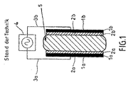
この発明は、物品の収容室(13)が絶縁材料から成る一つの壁(11,11a,11b,12a,12b,12c,12d,12e)により形成され、その室の外面(15)には少なくとも二つの電極(16a,16b)が配置されていて、物品の収容室内において放電によって物品(14)を処理する装置(10)に関する。この発明は、壁(11)の内面(20)には両外部電極に対して容量的に連結された少なくとも一つの逆電極(21)が固定式に配置されていることを特徴とする。【Task】
To reproduce an apparatus for processing articles so that a reliable and predeterminable operating mode is possible during simple manufacturing.
[Solution]
In the present invention, the article storage chamber (13) is formed by one wall (11, 11a, 11b, 12a, 12b, 12c, 12d, 12e) made of an insulating material, and at least the outer surface (15) of the chamber is formed on the outer surface (15). The present invention relates to an apparatus (10) in which two electrodes (16a, 16b) are arranged and which treats an article (14) by electric discharge in the article accommodating chamber. The present invention is characterized in that at least one reverse electrode (21) capacitively connected to both external electrodes is fixedly arranged on the inner surface (20) of the wall (11).
Description
この発明は、請求項1の上位概念に基づく放電によって物品を処理する装置に関する。
The present invention relates to an apparatus for processing articles by electric discharge based on the superordinate concept of
この特許出願の意味において物品の処理の下で特に種々の物品の保存、消毒、滅菌或いは殺菌が理解されている。物品の場合には、例えば野菜或いは果物のような食料品が重要であるが、しかし化粧品、医療装置なども重要である。 In the sense of this patent application, the storage, disinfection, sterilization or sterilization of various articles is particularly understood under the treatment of the articles. In the case of articles, food products such as vegetables or fruits are important, but cosmetics, medical devices, etc. are also important.
しかしこの特許出願の意味において物品の処理は他の処理作用も包含し、この作用の場合には、例えば物品が漂白されるか、または酸化される。結局、処理との概念は一般に物品の表面修正も包含する。 However, in the sense of this patent application, the treatment of the article also includes other processing actions, in which case, for example, the article is bleached or oxidized. After all, the concept of processing generally encompasses surface modification of articles.
しかし特に専用ではない、この発明は、収容室に発生された放電によってオゾン及び紫外線放射が物品の部分的或いは全体的滅菌の目的のために発生される装置に関する。この種の処理は特に装置と日用品の場合には、医学的且つ医薬的分野から考慮され、しかし化粧品や食料品の場合にも考慮される。 However, this invention, which is not particularly dedicated, relates to an apparatus in which ozone and ultraviolet radiation are generated for the purpose of partial or total sterilization of articles by a discharge generated in a containment chamber. This kind of treatment is considered from the medical and pharmaceutical field, especially in the case of equipment and daily necessities, but also in the case of cosmetics and foodstuffs.
医学的商品や消費物は殆どの場合に殺菌されなければならない。これは、すべての生きている微生物並びにその休眠状態(胞子)の滅殺と理解される。薬学的包装、化粧品、果実、果物、或いは薬味のような食料品の場合には、しばしば病原細菌(バクテリア)の減少(消毒/保存)で十分である。殺菌或いは消毒するために、放電の助けなしに加えられ、放電の使用が殺菌物の材料と幾何学形状に基づく全連続的方法が利用される。古典的方法は過熱蒸気による処理(オートクレーブ、T>121℃)である。受熱性材料、例えば重合体を基礎とした合成樹脂の増加する使用に基づいて、低温で作動する「冷却」殺菌消毒方法の必要性が存在する。これは、同様に最高50℃にて処理されなければならない食料品や化粧品の病原細菌負荷の減少のために適用される。 Medical goods and consumables must be sterilized in most cases. This is understood as the killing of all living microorganisms as well as their dormant state (spores). In the case of foodstuffs such as pharmaceutical packaging, cosmetics, fruits, fruits or spices, a reduction (disinfection / preservation) of pathogenic bacteria is often sufficient. In order to sterilize or disinfect, an all-continuous method is applied that is applied without the aid of an electrical discharge and the use of electrical discharge is based on the material and geometry of the sterilized material. The classic method is treatment with superheated steam (autoclave, T> 121 ° C.). There is a need for “cooling” sterilization methods that operate at low temperatures based on the increasing use of heat-receptive materials, such as synthetic resins based on polymers. This applies for the reduction of the pathogenic bacterial load of foodstuffs and cosmetics that also have to be processed at up to 50 ° C.
全体的或いは部分的滅菌に対する重要な低温処理はエチレン酸化物(EO)殺菌、放射性照射(β,γ照射)による或いは紫外線照射による殺菌である。その外に、二三年来、ガスプラズマ殺菌はH2 O2 に基づく或いは過酸に基づく例えば米国特許第4643876号明細書(特許文献1)により或いは欧州特許第0278623号明細書(特許文献2)により、例えば米国特許第5084239号明細書(特許文献3)により或いは欧州特許第0387022号明細書(特許文献4)により著しく重要になり、殺菌する作用は実質的に微生物の胞子被膜を酸化するH2 O2 蒸気により行われる。室温にて使用され得る異なる非常に強力な酸化剤はオゾン(O3 )である。そのオゾンは、以前から水状溶液で飲み水を滅菌するために、紙を塩素なしに漂白するために、或いはガスとしてあらゆる種類の食料品のバクテリアを減少させるために並びに室内空気を洗浄して臭いを中和させるために、使用されている。オゾンは他の化学的酸化剤に対する価格の適正で環境にやさしい代替物である、というのは、オゾンが空気に含有された酸素から発生され得て、毒性残留物を発生しなく、むしろ処理後に再び酸素に分解するからである。医学的製品を殺菌するためにガス状オゾンは濃度が十分に高く且つ同時に比較的高い湿度(>85%)が存在する(例えばIshizaki他著、「オゾンによるシラス胞子の不活性」J.Appl.Bacteriol.60,第67ー72頁(1986)を参照) 場合に同様に使用され得る。 Important low temperature treatments for total or partial sterilization are sterilization by ethylene oxide (EO) sterilization, radioactive irradiation (β, γ irradiation) or by ultraviolet irradiation. In addition, gas plasma sterilization has been based on H 2 O 2 or based on peracid for a few years, for example according to US Pat. No. 4,643,876 or EP 0 278 623 (Patent Document 2). By, for example, US Pat. No. 5,084,239 (Patent Document 3) or European Patent No. 0387822 (Patent Document 4), the disinfection action is substantially H which oxidizes the spore coat of microorganisms. Performed with 2 O 2 vapor. A different and very powerful oxidant that can be used at room temperature is ozone (O 3 ). Its ozone has long been used to sterilize drinking water with aqueous solutions, bleach paper without chlorine, or as a gas to reduce bacteria in all types of food products, as well as clean indoor air. Used to neutralize odors. Ozone is a cost-effective and environmentally friendly alternative to other chemical oxidants, because ozone can be generated from oxygen contained in the air and does not generate toxic residues, but rather after treatment It is because it decomposes again into oxygen. In order to sterilize medical products, gaseous ozone is sufficiently concentrated and at the same time relatively high humidity (> 85%) is present (eg Ishizaki et al., “Inactivation of Shirasu Spores by Ozone” J. Appl. Bacteriol. 60, pp. 67-72 (1986)).
オゾンにより殺菌する多数の公知の装置の場合には、オゾンは本来の処理室で発生されなく、むしろ立体的にその処理室から分離したオゾン発生器で発生され、次に管や弁を介して処理室に供給される。部分的になお臨床試験である例えば米国特許第3719017号明細書(特許文献5)による或いは国際特許出願公開第03/39607号明細書(特許文献6)による低圧方法並びに例えば米国特許第5868999号明細書(特許文献7)による大気圧にて作動される方法が公知である。オゾンの発生は通常には酸素含有ガスに於ける高電圧で励起された「絶縁的に損傷される放電」の作動により行われる。このタイプのガス放電は電極の現存電気絶縁に基づいて障壁放電と呼ばれる。障壁放電は酸素分子を化学的に非常に活性原子酸素に分解し、その活性原子酸素がすぐにオゾン(O3 )に対する次の酸素分子と結合している。この反応は非常に迅速に且つ発熱を伴う。オゾンは安定していなく、熱と触媒の影響下で(容器壁或いは殺菌物との接触)分解する。それ故、電極間の流束と化学的反応によって生じる熱は直接にオゾンを分解するために寄与しており、それ故に、オゾンにより殺菌する種々の装置の場合には、例えば米国特許第5002738号明細書(特許文献8)と米国特許第5169606号明細書(特許文献9)を参照して発生されたオゾン或いは放電電極を冷却することに特別に注意を向けられている。 In the case of many known devices that are sterilized by ozone, ozone is not generated in the original processing chamber, but rather in an ozone generator that is sterically separated from the processing chamber, and then through tubes and valves. Supplied to the processing chamber. Low pressure methods that are partly still in clinical trials, for example according to US Pat. No. 3,719,017 or WO 03/39607, as well as, for example, US Pat. No. 5,868,999. A method of operating at atmospheric pressure according to the document (Patent Document 7) is known. Ozone is usually generated by the action of an “insulatingly damaged discharge” excited by a high voltage in an oxygen-containing gas. This type of gas discharge is called a barrier discharge based on the existing electrical insulation of the electrodes. The barrier discharge chemically decomposes oxygen molecules into very active atomic oxygen, and the active atomic oxygen is immediately combined with the next oxygen molecule for ozone (O 3 ). This reaction is very rapid and exothermic. Ozone is not stable and decomposes under the influence of heat and catalyst (contact with container wall or sterilized material). Therefore, the heat generated by the flux between the electrodes and the chemical reaction contributes directly to the decomposition of ozone, and therefore in the case of various devices sterilized by ozone, for example, US Pat. No. 5,0027,381. Special attention is given to cooling the ozone or discharge electrode generated with reference to the specification (Patent Document 8) and US Pat. No. 5,169,606 (Patent Document 9).
滅菌や消毒に対する上記低温方法は次の欠点を有する:
・β照射とγ照射による殺菌は比較的に費用がかかり、厳しい安全措置を要する。この方法による食料品の処理はドイツや他の国々では許可されていない。
・陰影効果に基づいて、紫外線照射は複雑で三次元的幾何学形状をもつ製品の処理のために使用され得ない。
・4.5バールにおける圧力室内のEOによる殺菌は実質的に三つの欠点を有する。
The above low temperature method for sterilization and disinfection has the following disadvantages:
• Sterilization with β and γ irradiation is relatively expensive and requires strict safety measures. Food processing in this way is not allowed in Germany or other countries.
• Based on the shadow effect, UV irradiation cannot be used for the processing of products with complex and three-dimensional geometric shapes.
Sterilization by EO in the pressure chamber at 4.5 bar has substantially three drawbacks.
1.純粋EOが燃焼できる、それ故にEOがクロロフルオロカーボン(FCKWs)と混合される(12%EO、88%FCKWs)。オゾン層の損傷に基づいてFCKWsがかなり禁止されるので、代替物が必要とされる。 1. Pure EO can be burned, so EO is mixed with chlorofluorocarbons (FCKWs) (12% EO, 88% FCKWs). Alternatives are required because FCKWs are significantly prohibited based on ozone layer damage.
2.EOは有毒で発癌性である。 2. EO is toxic and carcinogenic.
3.EOの有毒性特性に基づいて殺菌物がおよそ12−15時間の処理後に空気により洗浄されなければならない。これは大量の医学的製品の迅速な殺菌を阻止する。 3. Based on the toxic properties of EO, the sterilization must be cleaned with air after approximately 12-15 hours of treatment. This prevents rapid sterilization of large quantities of medical products.
◆ガスプラズマ殺菌或いはオゾン水蒸気殺菌の場合には、製品が特殊な真空室に置かれなければならない、というのは、処理はおよそ0.5バールから20バールまでの圧力範囲で行われるからである。このために、十分な濃度で有効な作用物質の供給と一緒に費用のかかる真空技術(ポンプ、弁、圧力センサーなど)が必要である(蒸発器或いは昇華器、例えば米国特許第5876666号明細書(特許文献10)或いは例えば米国特許第5904897号明細書(特許文献11)を参照)。さらに、H2 O2 或いは過酸の使用の場合には、加熱された室が十分な蒸気圧を保証ために必要である、或いはオゾン殺菌の場合にはオゾンの分解を抑える電極の冷却が必要である。プラズマ殺菌の場合にはこのために、プラズマの励起が通常には13.56MHzと2.45GHzの周波数の際に行われる、即ち装備では比較的高い高周波数発生器が同調ネットワークと一緒に一体化されなければならない。 ◆ In the case of gas plasma sterilization or ozone steam sterilization, the product must be placed in a special vacuum chamber, because the processing is carried out in a pressure range from about 0.5 bar to 20 bar. . This requires expensive vacuum techniques (pumps, valves, pressure sensors, etc.) along with a supply of active agent in sufficient concentration (evaporator or sublimator, eg US Pat. No. 5,876,666). (See Patent Document 10) or US Pat. No. 5,904,897 (Patent Document 11), for example). In addition, when using H 2 O 2 or peracid, a heated chamber is necessary to ensure sufficient vapor pressure, or in the case of ozone sterilization, cooling of the electrode is necessary to suppress ozone decomposition. It is. For this purpose in the case of plasma sterilization, the excitation of the plasma usually takes place at frequencies of 13.56 MHz and 2.45 GHz, ie a relatively high high-frequency generator in the equipment is integrated with the tuning network. It must be.
その上、一般に、ガス状有効作用物質を使用する方法では、この作用物質が通例ではもはや全処理室に供給されることを確認すべきである。医学的物品や製品の殺菌は通例では処理後に微生物再成長を阻止するために包装で行われる。それ故に、この包装は半透明であり、即ち有効作用物質を透過し且つバクテリア胞子や微生物には不透過である孔を備えている。適切な材料は例えばタイベーク(Tyvek 登録商標: デュポン社) がある。それで包装は有効作用物質の別の障害を意味し、有効作用物質の速過ぎる化学的分解或いは蒸気凝固が包装の外面に起り得る。有効作用物質を発生器から処理室へ供給する場合には、頻繁に供給管或いは弁の表面において有効作用物質の濃度の更なる損失を生じる。 Moreover, in general, it should be ensured that in processes using a gaseous active agent, this agent is usually no longer supplied to the entire process chamber. Sterilization of medical articles and products is typically done in packaging to prevent microbial regrowth after processing. This package is therefore translucent, i.e. with pores that are permeable to active agents and impervious to bacterial spores and microorganisms. A suitable material is, for example, Tyvek (Trademark: DuPont). Packaging thus represents another obstacle to the active agent, and too fast chemical decomposition or vapor coagulation of the active agent can occur on the outer surface of the package. When the active agent is fed from the generator to the process chamber, there is often a further loss of the concentration of the active agent at the surface of the supply pipe or valve.
この発明は国際特許出願公開第03/59400号明細書(特許文献12)による装置から出発する。これには物品を処理する、即ち物品を殺菌する装置が記載されており、この装置では物品を殺菌するオゾンを発生させるために、放電が使用される。この刊行物の図1によると、外面に二つの平らな電極が配置されている消毒容器が設けられている。この容器の内部空間には、対応して平らで外部電極に平行な電極を備える電極構造が配置されている。
この発明は、先行技術から出発して、簡単な製造の際に確実な予め決定できる作動態様が可能であるように、請求項1の上位概念による物品を処理する装置を再現することを課題としている。
This invention is based on the object of reproducing an apparatus for processing an article according to the superordinate concept of
この発明はこの課題を請求項1の特徴事項により、特に特徴部分の特徴事項により解決し、即ち壁の内面に少なくとも一つの容積的に両外部電極に連結された逆電極が固定式に配置されていることを特徴としている。
The invention solves this problem by the features of
この発明の原理は、実質的に収容室の壁の外面に二つの電極を、壁の内面に一つの電極を固定式に配置させることにある。内部電極は容量的に両外部電極と連結されている。これは、両外部電極には交流電圧が印加でき、内部の容量的に連結された逆電極には外部電極からの電圧が単に誘導される。内部電極が絶縁されて、同様に外部電極から分離して且つ電圧供給ユニットから分離して配置されている。特に内部電極への電気的供給電線が設けられていない。それ故に、電気的供給電線を通過案内する収容室の壁の穿孔が余計である。 The principle of the present invention is to substantially arrange two electrodes on the outer surface of the wall of the storage chamber and one electrode on the inner surface of the wall in a fixed manner. The internal electrode is capacitively connected to both external electrodes. This is because an AC voltage can be applied to both external electrodes, and a voltage from the external electrode is simply induced to the internal capacitively connected reverse electrode. The internal electrodes are insulated and similarly arranged separately from the external electrodes and from the voltage supply unit. In particular, no electrical supply wires are provided for the internal electrodes. Therefore, it is unnecessary to perforate the wall of the storage chamber that guides the electric supply wire through.
内部電極が壁の内面に固定式に配置されていることによって、三つの電極の非常に正確な位置決めが互いに可能である。壁の所定壁厚は外部電極の内部電極からの距離を非常に正確に与える。それにより、非常に正確な程度に予め決定できる表面放電を形成する可能性が生じる。この表面放電は内部電極の縁領域において、つまり直接に収容室内部で発火するので、放電は直接に収容室内で物品を処理するために発火する。それ故に、滅菌や消毒の場合において放電によって発生する紫外線照射或いはオゾンは直接に収容室内に配置された物品上に作用できる。 Due to the fixed arrangement of the inner electrodes on the inner surface of the wall, very precise positioning of the three electrodes is possible with respect to each other. The predetermined wall thickness of the wall gives the distance of the external electrode from the internal electrode very accurately. This creates the possibility of creating a surface discharge that can be predetermined to a very precise degree. Since this surface discharge is ignited in the edge region of the internal electrode, that is, directly in the inside of the storage chamber, the discharge is ignited for processing the article directly in the storage chamber. Therefore, ultraviolet irradiation or ozone generated by discharge in the case of sterilization or disinfection can directly act on the article placed in the storage chamber.
放電としてこの発明の装置は、障壁放電の特殊な技術的態様を意味し、表面障壁放電として参照される所謂表面放電を発生させる。この表面放電は最初にエス増田氏により述べられていた(エス増田外著、IEEE Trans. Ind. Appl. 24,第 223-231頁 1988 年、米国特許第4666679号明細書(特許文献13))。容積障壁放電とは異なって、放電は互いに平行に配置された電極の間の隙間で発火しなく、むしろ電極の一方を絶縁する表面や縁上で発火する。このタイプの障壁放電はオゾン発生の特に高い効率を特徴とする。 As a discharge, the device of the present invention represents a special technical aspect of a barrier discharge and generates a so-called surface discharge referred to as a surface barrier discharge. This surface discharge was first described by Mr. Masuda (S. Masuda, IEEE Trans. Ind. Appl. 24, pp. 223-231, 1988, US Pat. No. 4,666,679 (Patent Document 13)). . Unlike a volumetric barrier discharge, the discharge does not ignite in the gap between the electrodes arranged parallel to each other, but rather on the surface or edge that insulates one of the electrodes. This type of barrier discharge is characterized by a particularly high efficiency of ozone generation.
それ故に、放電はこの発明による装置では、表面放電として形成されて、それ故に特許文献12の図1の実施例において記載されている放電とは相違している。そこでは、両内部電極と容器の壁の内面との間のそれぞれに強制的に存在する空隙に基づいて容積放電が重要である。この種の容積放電の場合には、電極間の間隔が発生する放電にとって重要であるから、電極間の間隔が正確に保持されることが極めて重要である。この発明が出発する先行技術の場合には、内部電極構造の位置決めが必要に正確な程度には高い費用でしかできない。 Therefore, the discharge is formed as a surface discharge in the device according to the invention and is therefore different from the discharge described in the embodiment of FIG. There, volumetric discharge is important based on the air gaps that are forcibly present between the internal electrodes and the inner surface of the vessel wall. In the case of this type of volumetric discharge, it is very important for the discharge in which the gap between the electrodes is generated, so it is extremely important to maintain the gap between the electrodes accurately. In the case of the prior art from which this invention starts, the positioning of the internal electrode structure can be done only at a high cost to the extent necessary and accurate.
特許文献12による装置の場合には、オゾンは確かに既に閉鎖容器で発生され、容器には処理すべき物品が保持されている。無論、この種の障壁放電(容積放電)によって剛性壁を備える容器が使用されなければならないことが条件付けられる:一様な放電を保証するために、内外部電極が互いに平行に整合されて、しっかりと固定されなければならない。 In the case of the device according to Patent Document 12, ozone is certainly already generated in a closed container, and the container holds an article to be processed. Of course, this type of barrier discharge (volumetric discharge) requires that a vessel with a rigid wall must be used: the inner and outer electrodes are aligned parallel to each other and firmly to ensure a uniform discharge. And must be fixed.
しかし、これは、電極表面間の間隔の変更がこの種の放電への大きな影響を有しないから、特に全電極面に沿って実際に実現することはない。 However, this is not actually realized especially along the entire electrode surface, since changing the spacing between the electrode surfaces has no significant effect on this type of discharge.
オゾンにより物品を殺菌する欧州特許第0863772号明細書(特許文献14)に記載された装置の場合には、同様に収容室の壁の内面に固定式に配置された電極が設けられていない。ここでも、プラスチック容器に緩く設置された内部電極とこの図2による下電極の絶縁壁の間に少なくとも小さい空隙を生じるさせて、この下電極にプラスチックバックが載置する。それ故に、どのようにプラスチックバックをもつ内部電極が処理室内に固定式に配置された平面状両電極が位置決めされるかに依存して、そこでは異なる放電が発生される。 In the case of the apparatus described in European Patent No. 0863772 (Patent Document 14) for sterilizing articles with ozone, no fixedly arranged electrode is provided on the inner surface of the wall of the storage chamber. Here again, at least a small gap is created between the internal electrode loosely installed in the plastic container and the insulating wall of the lower electrode according to FIG. 2, and the plastic bag is placed on the lower electrode. Therefore, different discharges are generated there depending on how the planar electrodes, in which the internal electrodes with plastic bags are fixedly arranged in the processing chamber, are positioned.
この発明の装置は滅菌や消毒を行うのに使用する場合には比較的僅かな費用で且つ特別な安全措置の留意なしに物品の処理を可能とする。この発明の装置による例えば食料品の処理が認められている。 The apparatus of the present invention, when used for sterilization and disinfection, allows for the processing of articles at a relatively low cost and without the need for special safety measures. For example, food products are permitted to be processed by the apparatus of the present invention.
滅菌や消毒を行うのに使用した装置の場合にはオゾンと紫外線照射が直接に収容室の内部で発生されることによって、この発明の装置が複雑な三次元構造をもつ製品の処理も可能とする。 In the case of equipment used for sterilization and disinfection, ozone and ultraviolet radiation are generated directly inside the containment chamber, so that the device of the present invention can also handle products with complex three-dimensional structures. To do.
この発明の装置は十分に高い量のオゾンと紫外線照射を十分に長い時間にわたり閉鎖包装内部に準備できるので、温度感知性の医学的製品の滅菌或いは包装内部に存在する化粧品或いは食料品の消毒或いは部分滅菌が行われ得る。好ましくは包装内部の大気圧における処理が行われ得るので、費用のかかる真空解決策はなくて済む。この場合には、収容室の壁は、特許文献12とは異なって、柔軟に形成され得るので、収容室の壁に対して多数の材料が考慮でき、物品の従来の包装材料に助けを求められ得る。これは、輸送装置として或いは物品の収容装置としてこの発明の装置の使用を可能とする。 The device of the present invention can provide a sufficiently high amount of ozone and UV radiation for a sufficiently long time inside a closed package to sterilize temperature sensitive medical products or disinfect cosmetics or foodstuffs present inside the package or Partial sterilization can be performed. Preferably, processing at atmospheric pressure inside the package can be performed, eliminating the need for costly vacuum solutions. In this case, the wall of the storage chamber can be formed flexibly unlike Patent Document 12, so that a large number of materials can be considered for the wall of the storage chamber, and the conventional packaging material of the article is sought for help. Can be. This makes it possible to use the device according to the invention as a transport device or as an article storage device.
紫外線照射との組合せで有効作用物質、即ち例えばオゾンの発生は、例えば処理すべき製品の包装内部で、つまり収容室内部で大気圧空気における放電によって起こる。このために、例えばポリエチレン(PE)或いは他の重合体(PA,PVC,PET,...)のような合成樹脂から製造される包装の外部には少なくとも二つの金属電極が取り付けられるので、金属と絶縁物の間に空隙が生じない。これは、最も簡単な場合には、薄い金属箔の貼り付けによって或いは印刷(スクリーン印刷など)或いはPVD(物理的蒸気沈殿)方法による蒸着によって実現され得る。包装外面に取り付けられた電極は電圧供給ユニットと電気的に接続され得て、この際に交流電圧が供給される。電圧の振幅は好ましくは若干kVから最高20kVまでであり、周波数は好ましくは1ー30kHzである。外部電極の互いの間隔は、最高に設定された電圧の際に外気では電気遮断が生じないように選定されている。代用として或いは補充として、両外部電極間には電気遮断を阻止するために一つの絶縁部分、即ち絶縁障壁の電極が配置されている。 Generation of an active agent, for example ozone, in combination with UV irradiation occurs, for example, by discharge in atmospheric air inside the packaging of the product to be treated, ie inside the containment chamber. For this purpose, at least two metal electrodes are attached to the outside of the package made from synthetic resin such as polyethylene (PE) or other polymers (PA, PVC, PET,...) There is no gap between the insulator and the insulator. In the simplest case, this can be achieved by applying a thin metal foil or by vapor deposition by means of printing (such as screen printing) or PVD (physical vapor precipitation). The electrodes attached to the outer surface of the package can be electrically connected to a voltage supply unit, in which an alternating voltage is supplied. The amplitude of the voltage is preferably slightly from kV up to 20 kV and the frequency is preferably 1-30 kHz. The distance between the external electrodes is selected so that electrical interruption does not occur in the outside air when the voltage is set to the maximum. As an alternative or as a supplement, an insulating part, i.e. an insulating barrier electrode, is arranged between the external electrodes to prevent electrical interruption.
外部電極に対向位置する壁の内面には、逆電極として、例えば同様に銅箔或いはアルミニュウム箔から成る金属構造が貼り付けられ、その箔は外部励起電極の寸法より僅かに少ない寸法を有する。内部電極は容積的に連結された逆電極である。これは、電気的に「浮遊する」、即ち包装の外部には、逆電極の金属接続電線が存在しない。外部電極と同様に、この電極は直接に壁の内面に取り付けられる(貼り付けられ、印刷され、或いはPVD蒸着法により塗布される)。点火磁界強さが達成されるとすぐに、プラズマは絶縁物に向いている内部電極の縁に沿う遷移領域の形態で広がる。このプラズマは電子的に励起された分子や原子種、特に空気の酸素からのオゾンの再組合せによって自由電子、イオン、遊離基(例えば原子酸素)及び紫外線照射を発生させる。発生されるオゾンの量は遷移領域の長さに比例する。それ故に、容積的に連結された逆電極が出来るだけ長い縁辺を有するならば、有益である。 On the inner surface of the wall facing the external electrode, a metal structure made of, for example, a copper foil or an aluminum foil is attached as a reverse electrode, and the foil has a dimension slightly smaller than that of the external excitation electrode. The internal electrode is a volume-connected counter electrode. This is electrically "floating", i.e. there is no reverse electrode metal connection wire outside the package. Like the external electrode, this electrode is directly attached to the inner surface of the wall (attached, printed, or applied by PVD deposition). As soon as the ignition field strength is achieved, the plasma spreads in the form of a transition region along the edge of the internal electrode facing the insulator. This plasma generates free electrons, ions, free radicals (eg atomic oxygen) and ultraviolet radiation by recombination of ozone from electronically excited molecules and atomic species, especially oxygen from the air. The amount of ozone generated is proportional to the length of the transition region. It is therefore beneficial if the volume-connected counter electrode has as long an edge as possible.
所望の滅菌程度が達成されるまで、プラズマ発生は非常に長く作動される。これは、製品の幾何学形状や表面性質及び使用分野に依存する。 Plasma generation is activated for a very long time until the desired degree of sterilization is achieved. This depends on the product geometry, surface properties and field of use.
例えば柔軟に形成された包装が処理すべき物品の表面の一部を覆って、滅菌を阻止することを阻止するためには、直接に壁の閉鎖前に例えば溶接前に、空気或いは他の酸素含有ガス混合物の吹き付けによって僅かな過圧が収容室に発生され得る。さらに、オゾン処理の効率は、包装の内部の湿度の度合が溶接前に自由水霧或いは水滴による包装の洗浄によって上昇される。 For example, to prevent a pliable package from covering part of the surface of the article to be treated and preventing sterilization, air or other oxygen directly before closing the wall, eg before welding. A slight overpressure can be generated in the storage chamber by spraying the gas mixture. Furthermore, the efficiency of the ozone treatment is increased by cleaning the package with free water mist or water droplets before the degree of humidity inside the package is welded.
この発明の装置は、増田氏により公知の表面放電に関して明らかに修正されている表面放電による放電の発生を可能とする。新たな電極幾何学形状は、収容室内部で特に高いオゾン濃度をもつ特に効率的オゾン発生を可能とする。この方法の利点は、有効作用物質(例えばオゾンと紫外線照射)がそれが必要とされる箇所に、つまり包装の内部に発生されることである。さらに、処理が大気圧にて行われ得る(価格と時間節約)ので、費用のかかる真空技術が必要とされていない。 The device of the present invention allows the generation of a discharge by surface discharge which is clearly modified by Masuda with respect to the known surface discharge. The new electrode geometry enables particularly efficient ozone generation with a particularly high ozone concentration inside the containment chamber. The advantage of this method is that the active agent (eg ozone and UV radiation) is generated where it is needed, ie inside the package. In addition, expensive vacuum techniques are not required because processing can be performed at atmospheric pressure (price and time savings).
有効作用物質は包装の内部のみに発生され、電圧供給の遮断後に自動的に分解される。オゾンの分解のための半減期はおよそ20分であり、即ち長い排気時間或いは換気時間と空にする時間が省略される。O3 は有機物から酸素或いは酸化された分解製品に、即ち実質的にCO2 に分解するので、費用のかかる真空技術が必要とされていない。 The active agent is generated only inside the package and is automatically decomposed after the voltage supply is cut off. The half-life for the decomposition of ozone is approximately 20 minutes, i.e. long exhaust times or ventilation times and emptying times are omitted. Since O 3 decomposes from organics to oxygen or oxidized degradation products, ie substantially to CO 2 , no expensive vacuum technique is required.
別の利点は、活性有効作用物質を製造して処理空間へ供給するために、労力が必要とされていないことである。この費用節約に基づいて、この方法は僅かな価値を伴う製品にも適している。 Another advantage is that no effort is required to produce and deliver an active active agent to the processing space. Based on this cost savings, this method is also suitable for products with little value.
別の利点は、放電が作動される必要な周波数範囲のネット部分(代表的に数kHz)は同調ネットワークをもつ高周波数発生器より著しく安い費用で発生され得ることである。 Another advantage is that the net portion (typically a few kHz) of the required frequency range in which the discharge is activated can be generated at a significantly lower cost than a high frequency generator with a tuning network.
この発明の別の利点は、特に柔軟な一回使用包装が使用され得ることである。例えば特許文献12の図5と8による実施例により知られているように、剛性電極と内部電極の特殊電流通過ガイドをもつ剛性容器に比べて、この発明の装置の場合には、PE箔、貼り付けられた或いは印刷された電極をもつ材料から成る安価なリサイクル包装が使用され得る。電極は、直接に包装に貼り付けられるラベルの構成部材である。内部電極及び外部電極はラベルの構成部材として構成され得る。 Another advantage of the present invention is that particularly flexible single use packaging can be used. For example, as known from the embodiment according to FIGS. 5 and 8 of patent document 12, in the case of the device according to the invention, a PE foil, compared to a rigid container with a special current passing guide of rigid electrodes and internal electrodes, Inexpensive recycled packaging made of material with affixed or printed electrodes can be used. An electrode is a component of a label that is directly attached to a package. The internal electrode and the external electrode can be configured as components of the label.
本特許出願に特に記載された物品処理が滅菌或いはバクテリア減少、殺菌、消毒などを強調することに注目すべきである。無論、一連の別の処理や放電が一つの役割を演じる特に全く異なる種類の表面修正が考慮できる。この場合には、物品処理が放電の助けにより行われる本特許出願の表現は、特に例えばオゾン或いは紫外線照射のような放電が二次製品或いは作用を発生させることを意味する。しかし、物品処理が放電により行われるという表現はそのような装置と処理状態を含めて、物品処理、特に物品表面が直接に放電によって、つまりプラズマによって行われる。 It should be noted that the article processing specifically described in this patent application emphasizes sterilization or bacteria reduction, sterilization, disinfection, and the like. Of course, a completely different type of surface modification can be considered, in which a series of different treatments and discharges play a role. In this case, the expression of this patent application in which the article processing is carried out with the aid of a discharge means in particular that a discharge, for example ozone or UV radiation, generates a secondary product or action. However, the expression that the article processing is performed by electric discharge includes the apparatus and the processing state, and the article processing, particularly the article surface is directly performed by electric discharge, that is, by plasma.
放電がオゾン照射或いは紫外線照射を発生すべきである場合には、種々の物品の極めて大抵の包装状況では収容室に空気が存在するから、特別な作用物質が収容室に収納される必要がないことを注目すべきである。それ故に、この発明の装置は作用物質の分離した納入を必要としていない。 If the discharge should generate ozone or ultraviolet radiation, there is no need for special agents to be stored in the storage chamber because air is present in the storage chamber in most packaging situations for various articles. It should be noted. Therefore, the device of the present invention does not require separate delivery of the active substance.
他の使用の場合には、収容室への作用物質の納入は例えばガス混合物或いはガスの形態で確かに望まれ得て、有効である。 For other uses, delivery of the active substance to the containment chamber can certainly be desired and effective, for example in the form of a gas mixture or gas.
この発明の装置は電圧供給ユニットと接続できる。これは、電圧供給ユニットが装置の直接な構成部材ではなく、むしろ例えば固定箇所に配置され得る。例えば物品の輸送容器として形成され得る異なる装置は、放電を発生するために且つ物品を処理するために必要に応じて電圧供給ユニットと接続され、処理の実施後に電圧供給ユニットから再び分離され、つまり分解され得る。 The device of the present invention can be connected to a voltage supply unit. This is because the voltage supply unit is not a direct component of the device, but rather can be arranged, for example, at a fixed location. For example, different devices that can be formed as goods transport containers are connected to the voltage supply unit as necessary to generate the discharge and to process the article and are separated again from the voltage supply unit after processing has been carried out, i.e. Can be broken down.
この発明の好ましい構成によると、装置は輸送装置として及び物品の保存装置として又はそのいずれか一方として形成されている。これにより、電極の配列にまで実質的に従来の、つまり通常の輸送装置或いは物品、例えば食料品の保存装置をこの物品の処理装置として構成することが可能である。最も簡単な場合には、収容室を限定する壁が例えば合成樹脂から成る従来の食料品包装には両外部電極と内部逆電極が固定される。物品は従来の形式で包装され得て、この場合には、輸送装置は、他の言葉で言うと包装は従来の形式で閉鎖され得るので、この形式で収容室に、つまり輸送包装の内部に存在する物品が耐久的に保護されて収納される。物品の包装後に、つまりこの物品が閉鎖された輸送装置の内部に存在するならば、収容室の電圧供給ユニットと外部電極との接触によって、放電が発生され、滅菌或いは殺菌を実施するためにオゾンと紫外線照射を発生させる。特に壁がバクテリア不透過に且つガス不透過に又はそのいずれか一方の不透過に形成されるならば、処理の実施後に収容室にある物品の特に確実な保護が可能である。 According to a preferred configuration of the invention, the device is formed as a transport device and / or as an article storage device. Thus, it is possible to construct a substantially conventional or normal transport device or article, for example a food storage device, as a processing device for this article, up to an electrode array. In the simplest case, both external electrodes and internal reverse electrodes are fixed to a conventional food packaging in which the walls defining the storage chamber are made of synthetic resin, for example. Articles can be packaged in a conventional format, in which case the transport device, in other words, the package can be closed in a conventional format, so in this format in the containment chamber, i.e. inside the transport package. Existing articles are stored protected in a durable manner. After the packaging of the goods, i.e. if the goods are inside a closed transport device, a discharge is generated by the contact between the voltage supply unit of the containment chamber and the external electrode, and ozone is used to carry out the sterilization or sterilization. And generate UV irradiation. Particularly reliable protection of the articles in the storage chamber is possible after the treatment has been carried out, in particular if the walls are formed impermeable to bacteria and / or impermeable to gas.
物品の輸送装置として或いは保存装置としてのこの発明の装置の構成は、この種の装置の考慮できる割安な製造を可能とし、従来の輸送装置或いは物品の保存装置に対して単に補助的電極が取り付けられなければならない。この電極はしかし前もって記載されるように、例えば金属箔として貼り付けられ得るから、従来の輸送包装と保存包装に比べて実際にはほんの僅かな余分の費用が生じる。 The configuration of the device according to the invention as an article transport device or as a storage device allows for a reasonably inexpensive production of this type of device, with only auxiliary electrodes attached to a conventional transport device or an article storage device. Must be done. This electrode, however, can be applied, for example, as a metal foil, as previously described, so that in practice there is only a slight extra cost compared to conventional transport packaging and storage packaging.
さらに、この発明の構成では、物品の分離した保存装置或いは分離した処理空間或いは処理室が省略されるという利点が生じる。物品の保存と物品の処理は同じ容器内で行われ得る。 Further, the configuration of the present invention has the advantage that the storage device or the processing space or processing chamber in which the article is separated is omitted. The storage of the article and the processing of the article can be performed in the same container.
さらに、この発明の構成は、物品の処理が今や所謂「使用点」には実施され得て、つまり物品がどっちみち存在する箇所では処理が実施され得るので、補助輸送費が省略できる。それで、例えば果実の滅菌或いは殺菌は、果実がまさに収穫されたところで行われ、特に直接に収容室、つまり包装に果実の納入後に且つ包装の全体閉鎖後に行われる。 Furthermore, the configuration of the present invention allows the processing of articles to now be performed at so-called “use points”, that is, processing can be performed wherever the articles are present, thus eliminating the need for auxiliary transportation costs. Thus, for example, the sterilization or sterilization of the fruit takes place at the point where the fruit has just been harvested, in particular directly after the delivery of the fruit into the storage chamber, ie the packaging, and after the entire closure of the packaging.
この場合には、本来の策略は、包装の壁が絶縁的に阻止された放電を発生させる絶縁障壁を形成することにある。 In this case, the original strategy is to form an insulating barrier that generates a discharge in which the packaging wall is insulated.
この発明の別の好ましい構成によると、壁が電極を除いて物品の従来の包装により形成されている。この発明の装置の構造に対する電極の配列はこの形式で非常に僅かな補助的費用のみで済む。 According to another preferred configuration of the invention, the walls are formed by conventional packaging of the article except for the electrodes. The arrangement of the electrodes for the structure of the device according to the invention requires very little auxiliary costs in this way.
この発明の別の好ましい構成によると、壁は合成樹脂、特にPE(ポリエチレン)、PA(ポリアミド)、PVC(ポリ塩化ビニール)、PET(ポリエチレンテレフタレート)などから成る。これは、従来の包装材料を使用する可能性を提供する。 According to another preferred configuration of the invention, the walls are made of synthetic resin, in particular PE (polyethylene), PA (polyamide), PVC (polyvinyl chloride), PET (polyethylene terephthalate) and the like. This offers the possibility of using conventional packaging materials.
この発明の別の好ましい構成によると、壁はガス不透過である。これは、滅菌として実施された処理の場合には、新たなバクテリア発生の危険が生じることなしに、収容室内部に物品の耐久的に確実な納入を可能とする。 According to another preferred configuration of the invention, the walls are gas impermeable. In the case of a process carried out as sterilization, this enables a durable and reliable delivery of the article into the interior of the storage room without the risk of new bacterial generation.
この発明の別の好ましい構成によると、装置は一回使用包装として形成されている。これは所定物品の包装の従来の取り扱いを可能とする。 According to another preferred configuration of the invention, the device is formed as a single use package. This allows conventional handling of the packaging of a given article.
この発明の別の好ましい構成によると、装置は複数回使用包装として形成されている。これは、所定物品の際に有効に使用でき、より僅かな費用となり得る装置の再使用性を可能とする。 According to another preferred configuration of the invention, the device is formed as a multi-use package. This allows for reusability of the device which can be used effectively with certain articles and can be less expensive.
この発明の別の好ましい構成によると、両外部電極が電圧供給ユニットの接続接点と接続できる。最も簡単な場合には、電圧供給ユニットは二つの接続電線を備えていて、この場合には接続電線の端部が両外部電極と分解可能な電気接続できる接点を有する。同時に、電気接続の実現により、機械的に分解可能な接続が行われることが企図され得る。 According to another preferred configuration of the invention, both external electrodes can be connected to the connection contacts of the voltage supply unit. In the simplest case, the voltage supply unit comprises two connecting wires, in which case the ends of the connecting wires have contacts which can be electrically connected with both external electrodes. At the same time, it can be envisaged that the realization of an electrical connection makes a mechanically resolvable connection.
外部両電極が壁の外面に固定式に配置されていて、例えば外部に開放する外面を有する場合には、電圧供給ユニットの接続接点は例えば磁石の助けにより両外部電極との直接に接触する接点にもたらされ得る。この場合には、収容室を制限する壁が柔軟に形成され得ることが特に重要である。 When both external electrodes are fixedly arranged on the outer surface of the wall and have an outer surface that opens to the outside, for example, the connection contact of the voltage supply unit is a contact that makes direct contact with both external electrodes, for example with the aid of a magnet Can be brought to. In this case, it is particularly important that the wall that limits the accommodation chamber can be formed flexibly.
この発明の代用的実施態様の場合には、外部電極が電圧供給ユニットの供給電線の接続接点と直接に分解可能に接続できる差し込み接点を備えている。 In the case of an alternative embodiment of the present invention, the external electrode is provided with an insertion contact that can be connected to the connection contact of the supply wire of the voltage supply unit directly and removably.
最終的に、両外部電極を壁の外面に固定式に取り付けていなく、むしろこの場合に電圧供給ユニットの接続電線と固定式に接続されている両外部電極を、物品を処理するために直接に壁の外面に接近移動させることを可能とする。これも若干の使用の場合に有効である。確かにここで、壁の外面に対する外部電極の非常に正確な位置決めが実施されなければならないという問題を提供する。無論、この位置決めは外部から実施でき、それにより簡単な形式で、電極と壁の外面の間に空隙が生じないことが保証できる。さらに、このために、壁の外面には位置決めに対する外部電極の目印付けが設けられ得る。代用として、壁の外面には内部電極の正確な位置を示す目印付けも設けられ得る。 Finally, both external electrodes are not fixedly attached to the outer surface of the wall, but rather in this case both external electrodes that are fixedly connected to the connecting wires of the voltage supply unit are directly connected to process the article. It is possible to move closer to the outer surface of the wall. This is also effective for some uses. Indeed, this presents the problem that a very precise positioning of the external electrode with respect to the outer surface of the wall must be performed. Of course, this positioning can be performed from the outside, thereby ensuring in a simple manner that no gaps are created between the electrode and the outer surface of the wall. Furthermore, for this purpose, the outer surface of the wall can be provided with markings of the external electrodes for positioning. As an alternative, markings may be provided on the outer surface of the wall to indicate the exact location of the internal electrodes.
しかしながら、好ましくは、両外部電極が壁の外面に固定式に配置されていることが企図されている。 Preferably, however, it is contemplated that both external electrodes are fixedly arranged on the outer surface of the wall.
この発明の別の好ましい構成によると、壁は収容室に対する閉鎖可能な出入口を有する。この種の出入口は例えばドアにより形成され得て、このドアは例えば旋回自在に或いは移動自在にこの場合に特に固定式に形成された壁に取り付けられる。代用として出入口はスライドファスナーにより形成され得て、これは、壁が例えばバック状のスライドファスナーを備えた容器を形成するならば、特に有効である。 According to another preferred configuration of the invention, the wall has a closeable doorway to the receiving chamber. Such a doorway can be formed, for example, by a door, which is mounted, for example, in a pivotable or movable manner in this case, in particular in a fixedly formed wall. As an alternative, the doorway can be formed by a slide fastener, which is particularly effective if the wall forms a container with, for example, a back-like slide fastener.
最終的に分離可能な蓋を有する箱状或いはコップ状容器の収容室を形成する可能性も生じる。装置が例えば果実の輸送のために知られているように、その上面で柔軟な合成樹脂箔により閉鎖される下シェルを有するという可能性が考慮される。 There is also the possibility of forming a storage chamber for a box-shaped or cup-shaped container having a finally separable lid. The possibility is considered that the device has a lower shell which is closed on its upper surface by a flexible synthetic resin foil, as is known for example for the transport of fruits.
出入口は単に一回閉鎖できるが、しかし再び開放可能に構成され得る。 The doorway can be closed only once, but can be configured to be open again.
この発明の好ましい構成によると、壁は部分的に或いは全体的に柔軟に形成されている。壁が全体的に柔軟に形成されている場合には、例えばバック状容器を備える可能性が生じる。少なくとも部分的に或いは全体的に設けられ得る壁の柔軟な構成は、装置が必要とされないならば、装置を保存するためにほんの僅かな場所の必要性の利点をもたらす。装置は例えば折り重ねられる、或いは折り畳まれる。その外に、柔軟な壁は収容室内部の異なる大きさ容積を可能とできるので、例えば収容室内部の圧力の上昇によって収容室の容積の増加が達成できる。これは、影領域が物品の処理の際に例えばオゾンにより或いは紫外線照射により回避されるべきであるならば、特に好ましいので、全表面に沿う物品の処理が可能となる。 According to a preferred configuration of the invention, the walls are made partly or wholly flexible. In the case where the wall is formed to be flexible as a whole, for example, there is a possibility of providing a bag-like container. The flexible construction of the walls, which can be provided at least partly or wholly, provides the advantage of requiring only a few places to store the device if the device is not required. The device is for example folded or folded. In addition, the flexible wall can allow different sized volumes in the interior of the storage chamber, so that an increase in the volume of the storage chamber can be achieved, for example, by increasing the pressure in the interior of the storage chamber. This is particularly preferred if the shadow area is to be avoided during processing of the article, for example by ozone or by UV irradiation, so that processing of the article along the entire surface is possible.
しかし、壁の柔軟な構成との代用として、壁が実質的に剛性に形成されることが設けられ得る。これは、所定物品の場合に、例えば医学的器具或いは装置の場合に、この物品の先行技術の保存装置が既に剛性壁を備えるならば、ある環境の下で好ましい。この発明は、二つの外部電極と一つの内部電極を備えている気泡包装による装置を可能とする。 However, as an alternative to a flexible configuration of the wall, it can be provided that the wall is made substantially rigid. This is preferred under certain circumstances in the case of a given article, for example in the case of a medical instrument or device, if the prior art storage device for this article already comprises a rigid wall. The present invention enables a device with bubble packaging comprising two external electrodes and one internal electrode.
この発明の装置が少なくとも二つの外部電極と一つの内部電極を有しなければならないことに注目すべきである。この場合には、補助的別電極、例えば別の内部電極と別の対のこの内部電極に対して配置された外部電極を備えることが企図され得る。 It should be noted that the device of the present invention must have at least two external electrodes and one internal electrode. In this case, it can be envisaged to comprise an additional auxiliary electrode, for example an external electrode arranged for another internal electrode and another pair of this internal electrode.
この発明の別の好ましい構成によると、内部電極の内面及び縁辺又はそのいずれか一方が収容室内で自由に露出されている。内部電極の少なくとも辺が自由に、つまり開放して配置されていること、即ちこの電極が絶縁材料層により覆われていないことによって、放電が表面放電の形態で発生され得る。同時に、この幾何学形状は、放電が収容室に遮蔽されないで点火することを可能とする。それ故に、放電は、これが例えば特許文献12による図1の実施例に設けられるように、カバーにより本来の収容室に比べて遮蔽されない。これは処理の効率を上昇させる。 According to another preferred configuration of the present invention, the inner surface and / or the edge of the internal electrode are freely exposed in the accommodation chamber. Due to the fact that at least the sides of the internal electrode are arranged freely, i.e. open, i.e. this electrode is not covered by an insulating material layer, a discharge can be generated in the form of a surface discharge. At the same time, this geometry allows the discharge to be ignited without being shielded by the receiving chamber. Therefore, the discharge is not shielded by the cover compared to the original storage chamber, as this is provided, for example, in the embodiment of FIG. This increases the processing efficiency.
この発明の別の好ましい構成によると、内部電極は両外部電極に対して、内部電極から外部電極への垂直投射の場合に内部電極の輪郭が実質的に全体的に外部電極の輪郭の内部に存在するように、位置決めされ且つ寸法とされる。このために、特に内部電極と両外部電極は互いに直接に対向位置して配置されていて、単に収容室の絶縁壁が互いに分離されていることに注目すべきである。両外部電極は互いに引き離して配置され、分離した接続電線により電圧供給ユニットと接続されている。内部電極は特に二つのヘッドを有し、例えば実質的にバーベル状に形成され、この場合に両ヘッドが狭いバーを介して互いに電気的に接続されている。両ヘッドの面はそれぞれに連動された外部電極の面より小さい。内部電極を外部電極へ垂直に投射したならば、内部電極の輪郭が実質的に全体的に両外部電極の内部に存在する。この場合には、「実質的に」という表現は細い結合バーがこの考察では考慮されていないままであることを考慮すべきである。 According to another preferred configuration of the present invention, the inner electrode has an inner electrode contour substantially entirely within the outer electrode contour in the case of vertical projection from the inner electrode to the outer electrode. Positioned and dimensioned to exist. For this purpose, it should be noted in particular that the internal electrode and the external electrodes are arranged directly opposite to each other and that the insulating walls of the receiving chamber are simply separated from each other. Both external electrodes are arranged apart from each other, and are connected to the voltage supply unit by separate connection wires. The internal electrode has in particular two heads, for example formed substantially in the form of a barbell, in which case both heads are electrically connected to each other via a narrow bar. The surfaces of both heads are smaller than the surfaces of the external electrodes linked to each. If the internal electrode is projected perpendicularly to the external electrode, the outline of the internal electrode is substantially entirely inside both external electrodes. In this case, the expression “substantially” should be taken into account that the thin connecting bar remains not considered in this discussion.
この発明の別の好ましい構成によると、内部電極、特に内部電極の少なくとも一つのヘッドは多数の方向変更箇所をもつ輪郭を有する。この発明の構成は内部電極の特別に長い縁辺を可能とするので、放電の特に長い遷移領域が生じる。これにより、大量のオゾンや紫外線照射が発生される。 According to another preferred configuration of the invention, the internal electrode, in particular at least one head of the internal electrode, has a contour with a number of redirection points. The arrangement according to the invention allows a particularly long edge of the internal electrode, resulting in a particularly long transition region of the discharge. Thereby, a lot of ozone and ultraviolet irradiation are generated.
この場合には、方向変更箇所として、縁辺に沿って移行されるか、またはそれ自体に縁辺の曲率を変更するならば、方向を特に突然に変更しなければならない箇所が特徴付けられる。 In this case, the direction change point is characterized by a point where the direction must be changed suddenly if it is moved along the edge or if it changes the curvature of the edge to itself.
特に外部電極と内部電極は一つの対称平面に関して対称的に形成されている。無論、これは、強制的に必要とされていない。両外部電極と内部電極は非対称的に形成され得る。 In particular, the outer electrode and the inner electrode are formed symmetrically with respect to one symmetry plane. Of course, this is not mandatory. Both the external electrode and the internal electrode may be formed asymmetrically.
この発明の別の好ましい構成によると、収容室の内部には室外部より高い圧力が支配される。これは物品全表面に沿って物品の処理を可能とする。 According to another preferred configuration of the present invention, a higher pressure is governed inside the accommodation chamber than outside the chamber. This allows processing of the article along the entire surface of the article.
この発明の別の好ましい構成によると、収容室の内部には放電の作動の際に50hpAと150hpAの間の圧力、特に大気圧が支配される。これは、費用のかかる真空装備なしに装置の作動を可能とするので、割安な製造と装置の割安な作動とが可能となる。 According to another preferred configuration of the invention, a pressure between 50 hpA and 150 hpA, in particular atmospheric pressure, is governed inside the storage chamber during the discharge operation. This allows operation of the device without costly vacuum equipment, thus allowing for inexpensive manufacturing and inexpensive operation of the device.
この発明の別の好ましい構成によると、収容室の内部には補助的に処理すべき物品に対して酸素含有ガスを含有するガス混合物が含有されている。これは、放電によってオゾンの発生を可能とする。 According to another preferred configuration of the invention, the containment chamber contains a gas mixture containing an oxygen-containing gas for the article to be supplementarily processed. This makes it possible to generate ozone by discharge.
この発明の別の好ましい構成によると、収容室内の水蒸気含有量は特に水蒸気の供給によって上昇されている。これはオゾン処理の効率の改良を可能とする。 According to another preferred configuration of the invention, the water vapor content in the storage chamber is increased, in particular by the supply of water vapor. This makes it possible to improve the efficiency of the ozone treatment.
この発明の好ましい構成によると、内部電極は直接に特に空隙を残すことなしに壁に取り付けられる。この形式では一方では収容室の壁に内部電極を特別に簡単に組立てることが可能である、というのは、分離した固定要素が必要であることなしに、内部電極が例えば貼り付けられ、蒸着され、印刷される或いは何か他の方法で直接に壁に固定され得るからである。さらに、壁に内部電極を直接に取り付けることは、無論、外部電極に対して内部電極の非常に正確な位置決めを可能とする、というのは、外部電極からの内部電極の間隔が壁の壁厚によって設けられているからである。この場合には、この壁厚は例えば壁の製造工程に基づいて非常に狭い公差内で知られており、予め決定できる。それ故に、放電の物理的パラメータは非常に精密に予め決定され得る。 According to a preferred configuration of the invention, the internal electrode is directly attached to the wall without leaving any gaps in particular. In this form, on the one hand, it is possible to assemble the internal electrode on the wall of the containment chamber in a particularly simple way, without the need for a separate fixing element, for example the internal electrode being affixed and evaporated. Because it can be printed or fixed in some other way directly to the wall. Furthermore, attaching the internal electrode directly to the wall, of course, allows a very accurate positioning of the internal electrode with respect to the external electrode, because the spacing of the internal electrode from the external electrode depends on the wall thickness of the wall. It is because it is provided by. In this case, the wall thickness is known within a very narrow tolerance, for example based on the wall manufacturing process, and can be determined in advance. Therefore, the physical parameters of the discharge can be determined very precisely.
一様に且つこれと無関係に同じ理由から、外部電極が直接に特に空隙を残すことなしに壁の外面に取り付けられるならば、好ましい。 For the same reason, both independently and independently, it is preferred if the external electrode is directly attached to the outer surface of the wall without leaving any gaps in particular.
この発明の別の好ましい構成によると、電極は金属、特に銀、金、特殊鋼、アルミニューム、錫或いは銅から、或いはこれらの金属の少なくとも一つをもつ合金から成る。この発明の構成は、一回使用包装として形成された装置の場合には、例えば銅のような容易に酸化可能な金属が考慮されることを考慮している。 According to another preferred configuration of the invention, the electrodes consist of a metal, in particular silver, gold, special steel, aluminum, tin or copper, or an alloy with at least one of these metals. The configuration of the invention takes into account that in the case of a device formed as a single use package, an easily oxidizable metal such as copper is considered.
この発明の別の好ましい構成によると、少なくとも一つの電極が壁に貼り付けられる金属箔により形成されている。 According to another preferred configuration of the invention, at least one electrode is formed of a metal foil that is affixed to the wall.
代用として、少なくとも一つの電極が壁に印刷されて、蒸着される、或いはスパッター方法で塗布されている。これは、電極の特別に簡単且つ割安な製造を可能とする。 As an alternative, at least one electrode is printed on the wall, deposited or applied by sputtering. This allows for a particularly simple and inexpensive production of the electrodes.
電極は壁の外面に例えば筆跡として印刷され得る。 The electrodes can be printed on the outer surface of the wall, for example as handwriting.
電極は壁に、特に包装として形成された壁に固定できる、特に貼り付けできるラベルの構成部材として形成され得る。 The electrode can be formed as a component of a label that can be fixed, particularly affixed, to a wall, in particular to a wall formed as a package.
ラベルは例えば例えば電極の合成樹脂包装から成る。代用としてラベルは繊維材料或いは紙材或いは厚紙材料から形成され、又は例えばサンドイッチ構造の様式に応じて異なる材料の組合せを包含する。 The label is made of, for example, a synthetic resin package of electrodes. As an alternative, the label is formed from fiber material or paper material or cardboard material, or includes a combination of different materials, for example depending on the type of sandwich structure.
電極はラベルの構成部材として金属箔により形成され得る。特にラベルが複数の材料層から成る場合には、電極は材料層の一つに取り付けられ得る、例えば貼り付けられ、蒸着され、印刷されるか、又はスパッター蒸着され得る。 The electrode can be formed of a metal foil as a constituent member of the label. In particular when the label consists of a plurality of material layers, the electrodes can be attached to one of the material layers, for example applied, deposited, printed or sputter deposited.
ラベルは壁に接着によって或いは他の適した固定手段によって、場合によっては熱的溶着によって固定され得る。例えば合成樹脂箔から成る包装として形成された壁の場合には、特に電極を有するラベルを包装に貼り付けることが好ましい。 The label can be secured to the wall by gluing or by other suitable fastening means, possibly by thermal welding. For example, in the case of a wall formed as a package made of synthetic resin foil, it is particularly preferable to attach a label having an electrode to the package.
ラベルはその外面に、例えば印刷されている認証番号或いは充填番号或いはバーコードを支持し得る。このラベルには表示手段、例えばリトマス試験紙が付属されていて、この表示手段は物品の処理状態、例えば物品の達成された滅菌度合を表示する。この表示手段は例えばオゾン用のマーカーとしても形成され得て、このマーカーは所定の処理状態の達成のために或いは化学的処理の実施後に色カバーを示す。 The label may carry on its outer surface, for example, a printed authentication number or fill number or bar code. The label is accompanied by display means, for example litmus paper, which indicates the processing status of the article, for example the degree of sterilization achieved of the article. This display means can also be formed, for example, as a marker for ozone, which indicates the color cover for achieving a predetermined processing state or after performing a chemical treatment.
特に電極が貼付け可能な要素、例えばラベルの構成部材である場合には、電極は特に簡単且つ割安な形式にて製造され、壁に固定されている。同時に物品の包装として形成された壁の場合には特別に薄い包装材料が選定され得る。壁の熱的負荷はプラズマの作動の際に電極の付近で最大であるから、ラベルの厚さの適切な選択によって包装の平均熱的負荷はこの領域において減少され得る。それによりプラズマが包装の損傷を生じ得るまで、プラズマはより長く作動され得る。ラベルの適切な厚さ構成によって壁自体は非常に薄い、破壊的熱負荷の危険がプラズマの作動の際に生じることなしに、例えば50μmの壁厚をもつ包装箔として形成され得る。 Especially when the electrode is a stickable element, for example a component of a label, the electrode is manufactured in a particularly simple and cheap manner and fixed to the wall. At the same time, a particularly thin packaging material can be selected in the case of walls formed as packaging for the article. Since the wall thermal load is greatest in the vicinity of the electrodes during plasma operation, the average thermal load of the package can be reduced in this region by appropriate selection of the label thickness. The plasma can be run longer until it can cause damage to the package. With the appropriate thickness configuration of the label, the wall itself is very thin and can be formed as a packaging foil with a wall thickness of, for example, 50 μm, without the risk of destructive heat loading occurring during plasma operation.
電極或いは電極を有するラベルが共通作業工程における装置によって壁の両面に、特に包装箔の両面に取り付けられるならば、壁に電極を特に好ましく確実に且つ簡単に固定することが行なわれる。例えば電極を取り付ける装置は二つの移動可能なスタンプを備えており、そのスタンプの間に壁が配置されている。このスタンプはその自由な互いに移動できる端部において取り付けるべき電極或いはラベルを有する。電極或いはラベルが壁と接触するまで、スタンプは壁の両面に当達される。壁に電極或いはラベルを接着固定の場合には電極或いはラベルがその接着面により予め壁に移動される。 If the electrodes or labels with electrodes are attached on both sides of the wall, in particular on both sides of the packaging foil, by means of a device in a common working process, the electrodes are particularly preferably reliably and simply fixed to the wall. For example, the device for attaching the electrode comprises two movable stamps, and a wall is arranged between the stamps. The stamp has an electrode or label to be attached at its free movable end. The stamp is applied to both sides of the wall until the electrode or label contacts the wall. When the electrode or label is bonded and fixed to the wall, the electrode or label is moved to the wall in advance by the bonding surface.
スタンプは必要な押圧により電極或いはラベルを直接に壁面に印刷される。浮き出し印刷も場合によっては熱的効果の助けによっても可能である。 The stamp is printed directly on the wall surface with electrodes or labels by the necessary pressing. Embossed printing is possible in some cases with the aid of thermal effects.
共通の装置による共通の作業工程において壁に電極或いはラベルを取り付けることによって、壁に電極を互いに相対的に軽減した位置決めが可能である。電極の互いの相対位置はそのような装置によって特に簡単な形式で達成でき、非常に正確な程度に予め決定できる。 By attaching electrodes or labels to the wall in a common working process with a common device, positioning of the electrodes on the wall can be made relatively reduced. The relative position of the electrodes with respect to each other can be achieved in a particularly simple manner by such a device and can be predetermined to a very precise degree.
全電極、即ち内部電極及び外部電極はラベルの構成部材として形成されていることは、特に好ましい。この場合には、両外部電極は共通のラベルにより支持され得る。 It is particularly preferable that all the electrodes, that is, the internal electrode and the external electrode are formed as components of the label. In this case, both external electrodes can be supported by a common label.
この発明の別の好ましい構成によると、少なくとも一つの電極が電気を伝導して光学的に透明な、つまり光透過性材料から成る。このために、例えばインジウム錫酸化物(ITO=インジウムチタン酸化物)或いは比較可能な材料、特に金属酸化物が問題である。電気伝導して光学的に透明な、つまり光透過性の材料は、例えばガラス瓶或いは透明な合成樹脂箔のような透明な或いは透き通った容器の場合には、これら電極が任意の形態に光学的に省略されるか、或いは全く光学的に妨害して配置されることなしに、内外部電極を設ける可能性を提供する。 According to another preferred configuration of the invention, at least one electrode conducts electricity and is optically transparent, i.e. made of a light transmissive material. For this purpose, for example, indium tin oxide (ITO = indium titanium oxide) or comparable materials, in particular metal oxides, are problematic. In the case of a transparent or transparent container such as a glass bottle or a transparent synthetic resin foil, the electrically conductive and optically transparent material, i.e., a light transmissive material, can be optically formed into an arbitrary shape. It offers the possibility of providing internal and external electrodes, either omitted or arranged without any optical interference.
この発明の別の好ましい構成によると、両外部電極の間には0.5と20kVの間の交流電圧が100Hzと100MHzの間、特に1と30kHzの間の周波数を備えて印加されている。これは特に効率的プラズマ発生を可能として、単に割安な電圧供給ユニットを必要とする。 According to another preferred configuration of the invention, an alternating voltage between 0.5 and 20 kV is applied between both external electrodes with a frequency between 100 Hz and 100 MHz, in particular between 1 and 30 kHz. This enables particularly efficient plasma generation and simply requires a cheap voltage supply unit.
この発明の別の好ましい構成によると、放電が表面障壁放電である。これは特に効率的オゾン発生とそれと共に物品の特別に効率的処理とを可能とする。 According to another preferred configuration of the invention, the discharge is a surface barrier discharge. This allows for particularly efficient ozone generation and a particularly efficient treatment of the articles along with it.
この発明の別の好ましい構成によると、収容室の内部には表示手段が配置されており、その表示手段は物品の処理状態を示す。例えば表示手段はリトマス紙により準備され、そのリトマス紙は物品の達成された滅菌度合を例えば現行PH値などの表示によって示す。他の処理状態も示され得る。表示装置は特に完全に閉鎖されている収容室内部に存在することが好ましい。それ故に、処理状態を確認するために収容室内部に配置された物品への直接的作用はなくても済むので、収容室は例えば一回使用包装の形態では、所望の滅菌度合が達成されているか否かを確認するために、開放される必要がない。 According to another preferred configuration of the present invention, display means is arranged inside the storage chamber, and the display means indicates the processing state of the article. For example, the display means is prepared with litmus paper, which indicates the degree of sterilization achieved of the article, for example by displaying the current PH value or the like. Other processing states may also be indicated. It is preferable that the display device exists in the interior of the housing chamber that is completely closed. Therefore, since it is not necessary to directly act on the articles arranged in the storage chamber in order to check the processing state, the storage chamber can achieve a desired degree of sterilization, for example, in the form of single use packaging. There is no need to open it to see if it is.
この発明の別の利点は、引用されていない従属請求項に基づいて並びに図に示された多数の実施例の次の詳細な説明から明らかになる。 Further advantages of the invention emerge from the following detailed description of the numerous embodiments shown on the basis of the unquoted dependent claims and in the figures.
この発明の装置は図3と図4の実施例に基づいてその全体を符号10で示される。これに関して、見易さや簡単にするために異なる図における同じ或いは比較可能な部材或いは要素が同じ符号により部分的に小さいアルファベットを添えて表示されることに注目すべきである。
The apparatus of the present invention is designated generally by the
この発明の装置が記載される前に、まず最初に図1に基づいて容積放電の機能原理が記載される。 Before the device of the invention is described, the functional principle of volumetric discharge is first described on the basis of FIG.
図1は、表面電極として形成されている第一電極1aを示す。この電極に対向位置して実質的に同じ大きさの第二電極1bが配置されているので、プレートコンデンサの種類の配列が生じる。各電極には一つの絶縁障壁2a、2bが付属されており、これら絶縁障壁はそれぞれに両電極1a、1bの間に配置されている。一つの層或いは一枚のプレートの絶縁材料から成る絶縁障壁2aは第一電極1aであり、第二絶縁障壁2bは第二電極1bに付属され、それぞれにこの第二電極に固定されている。両電極は接続電線3a、3bを介して電圧供給ユニット4と接続されている。これは交流電圧を発生させるので、両電極1a、1bは異なる電位である。
FIG. 1 shows a first electrode 1a formed as a surface electrode. Since the
周波数と電圧の適切な選択の場合には、絶縁障壁2a、2bの間にプラズマ5の形態の放電が発生する。このプラズマは簡略化された観察の場合に電極が互いに最も短い間隔を有するそれぞれに両電極1a、1bの間の領域に生じる。このプラズマ5は容積を充填する、それ故に、この種の放電では容積放電を話題にする。この場合には、両電極1a、1bが互いに非常に正確に位置きめされるのが重要である、というのは、目標位置のそれぞれの偏差が異なる間隔を導き、それ故に、プラズマ5の異なる構成も導く。
In the case of appropriate selection of frequency and voltage, a discharge in the form of plasma 5 occurs between the insulating
図2に基づいて、まず最初に一般にこの発明の装置に使用される表面放電の原理が記載されるべきである。さらに、接続電線3a、3bを介して交流電圧を第一電極1aと第二対の電極1b、1cに与える電圧供給ユニットが設けられている。それ故に、電極1b、1cは同じ電位であり、それ故に、電極1aは他の電位である。
Based on FIG. 2, the principle of surface discharge generally used in the device of the invention should first be described. Furthermore, a voltage supply unit is provided that applies an alternating voltage to the first electrode 1a and the second pair of
電極1aと電極1b、1cの間に一つの絶縁障壁2が配置されている。両電極1b、1cが互いに間隔を置いていることに注目すべきである。
One insulating
周波数と電圧の適切な選択の場合には、実質的に電極1b、1cの縁に沿って遷移領域、即ち表面プラズマ5a或いは5bの形態の放電が発生する。放電が実質的に電極1b、1cの縁辺に沿って生じるから、人は容積プラズマを話題にしなく、むしろ表面放電を話題にする。
With an appropriate choice of frequency and voltage, a discharge in the form of a transition region, ie surface plasma 5a or 5b, occurs substantially along the edges of the
図3に基づいて今やこの発明の装置10が説明されるべきである:
装置10は図3により概略的横断面図に図示され、床部材12a、蓋部材12c、左側面部材12dと右側面部材12bを備える壁11を包含する。この壁11はその壁部材12a、12b、12c、12dにより任意の物品の収容室13を限定して形成する。図3は例として示された長方形物品14を示し、この物品は直接に蓋壁12cに当接する。例として示された物品14はこの場合には例えば蓋壁12cに固定され得る。物品14が単にルーズに収容室14に収納される場合には、この物品14は重力を考慮して壁11の蓋部材12cに載置できる。この場合には、図3はヘッドを示し、これは無論次の観察と説明にとってとるに足らない。
The
The
補足的に、収容室がすべての面で包囲されていることに注目すべきである。それ故に、壁11には図示されていない前壁部材が付属されている。壁11の後壁部材が図3に示され、12eで示される。
In addition, it should be noted that the containment chamber is surrounded on all sides. Therefore, a front wall member (not shown) is attached to the
壁11は合成樹脂或いは任意の他の絶縁材料から形成され得る。特に壁11はその全周辺に沿って一定壁厚Wを有する。これは無論必要ではない。
The
壁11は柔軟な材料から形成されるか、または比較的に堅く形成され得る。これは装置10の使用目的に依存している。
図3の実施例では、まず最初に簡略化のために、壁11が比較的堅い材料からなると仮定される。
In the embodiment of FIG. 3, it is first assumed for simplicity that the
図3では、壁11の外面15には第一外部電極16aと第二部電極16bが取り付けられて固定されていることが認識される。両電極16a、16bと壁11の外面15の間には空隙が残っていなく、むしろ両電極16a、16bが直接に壁11の外面15に取り付けられることに注目すべきである。
In FIG. 3, it is recognized that the first
両電極16a、16bは電圧供給ユニット18の付属接続電線17a、17bを介して適した周波数と適した電位の交流電圧を供給される。それぞれの電圧供給電線17a、17bの自由端19a、19bは対応する電極16a、16bと分離可能に電気接触されている。
Both
外面15に対向位置する壁11の内面20には、内部電極21が取り付けられる。この内部電極21は、電極21と壁11の間に空隙が残ることなしに、直接に壁11の内面20に固定されている。
An
端19a、19bが付属電極16a、16bと分離可能であるから、壁11は壁に固定された電極16a、16b、21と収容室13の内部に配置された物品(例えば14)によろ操作可能なユニットを形成する。それ故に、この装置10は物品14の輸送装置或いは保存装置として適している。装置は必要に応じて、必要であって、収容室13の内部に存在する物品の処理が行われるときに、電圧供給ユニット18の接続電線17a、17bと接続されている。
Since the
装置が作動状態であるならば、内部電極21の辺22a、22bに沿って放電が発生し、しかも、表面放電、つまり遷移領域の種類のプラズマが発生する。生じる遷移領域は図3に点線で示され、23により示される。見易くするために図3aにおいて遷移領域23が線影で概略的に図示され、この図は内部電極21と外部電極16aの図3に関して左縁領域の拡大切断面を概略的に示す。縁辺に沿う遷移領域の種類の発生したプラズマは糸状プラズマであり、つまりAPGプラズマではなく、それ故に、グロープラズマでない。収容室13の内部の放電23の発生によって、オゾンと紫外線照射が発生される。オゾンと紫外線照射は次に作用物質と呼ばれている。この作用物質は収容室13にある物品14と共働して、この物品を例えば滅菌し、消毒し、殺菌し得る。他の処理種類も、どんな物品が重要であるかに応じて、且つ収容室13にあるガス或いはガス混合物に依存して、考慮できる。それで、収容室13にある物品14の漂白、酸化或いはそのような表面修正が考慮できる。
If the device is in operation, a discharge occurs along the
内部電極21が両外部電極16a、16bに対する容量的に連結された逆電極を意味することに注目すべきである。それ故に、内部電極21は電圧供給ユニットの収容室13の外部に配置されたなんらかの電圧供給電線と接続されていない。内部電極21はそれと完全に無関係である。電極には電圧が専ら外部電極16a、16bを介して誘導される。
It should be noted that the
内部電極21と両外部電極16a、16bは直接に壁11に固定されていることによって、電極16a、16b、21の位置は互いに相対的に一義的に予め決定される。図3による二重矢印yの方向に電極相互の確定すべき間隔は、壁11の壁厚w(図3a)に基づいてこの領域に精密に定義されている。それ故に、表面放電23は非常に正確な程度に予め決定され得る。
Since the
装置10の壁11の壁厚wを所望の表面放電23の必要要件に適合させる可能性が存在することに注目すべきである。多方、電極幾何学形状の変更によって、室壁11の現行の変更しない壁厚wが考慮され得る。両外部電極16a、16bは平面Eに沿って互いの間隔xだけ間隔を置いている。この間隔xは、電極16a、16b間の破壊放電が阻止されるように選定されている。必要な場合には、両電極16aと16bの間にも図3に図示されていない絶縁物が配置され得る。
It should be noted that there is a possibility to adapt the wall thickness w of the
図4はこの発明の装置10の第二実施例を示し、実施例では装置の壁11が第一壁部分11aと第二壁部分11bから成り立つ。この第一壁部分11aは例えば比較的に堅く或いは剛性に形成され、一種の支持板を準備し得る。第二壁部分11bは柔軟な包装、例えば箔により準備され得る。両壁部分11a、11bは結合領域24aと24bの領域において互いに固定式に連結される、例えば溶接されるので、物品14の完全に閉鎖された収容室13が準備されている。さらに、図4には長方形の形態の物品14が単に非常に概略的に示されている。
FIG. 4 shows a second embodiment of the
電極16aと16bの配列は図3による電極配列と比較できるので、この明細書にはこの代わりに放棄されている。特性として図4による実施例では、装置10に送風ユニット25が付属されおり、この送風ユニットは接続パイプ26と支持板11aの通過開口27を通して空気を収容室13内に送り込む。通過開口27は弁によって再び閉鎖できるので、物品14の処理後に装置の完全ガス密度或いはガス不透過性が達成できる。
Since the arrangement of the
空気の吹き付けを、柔軟な壁11bが物品14の上面28から取り除かれ得ることで可能とするので、物品14が全ての面で空気により包囲されている。これは、物品14の表面の均一な処理を必要とする。
Since the blasting of air is made possible by the
重力に基づき物品14がほぼ強制的に材料範囲により壁部分11aの内面に載置するので、図4は単に概略的に理解すべきであることに注目すべきである。補足的にこの装置は例えば篩或いは振動器によって処理中に移動され得ることが引用されるので、物品14のそれぞれに異なる範囲が壁11の内面に載置するので、同様に物品の均一或いはより均一な処理が可能となることが配慮されている。
It should be noted that FIG. 4 should only be schematically understood because the
図4の実施例による室にガスを送るのに代えて、且つ収容室13における過圧の発生によって同じ効果が壁11の外部に負圧が発生されることによって達成され得る。
Instead of sending gas into the chamber according to the embodiment of FIG. 4, and the same effect can be achieved by generating a negative pressure outside the
最終的に、送風機25、接続区間26と通過開口27を介して特にガス或いはガス混合物が部分的に別の作用物質が収容室13に導入され得ることが注目されるべきである。これは特に表面修正では重要である。図4による装置の場合にも、外部電極16aと16bから接続電線17a、17bの端部19a、19bの分離が企てられるので、装置10は分離可能に電圧供給ユニット18と接続でき、そして物品14の輸送装置或いは収容装置として用いられ得る操作可能なユニットを意味する。
Finally, it should be noted that another active substance, in particular a gas or a gas mixture, can be introduced into the receiving
図5と図6に基づき、今や電極の幾何学形状も説明される:
図5と図6は、図4の観察矢印に沿うそれぞれ一つの投射図を示し、この場合には、単に内部電極21と外部電極16aと16bが示されている。言い換えると、壁11b、物品14と壁部分11aは見易くするために省略されている。
Based on FIGS. 5 and 6, the electrode geometry is now also explained:
5 and 6 show one projection view along the observation arrow of FIG. 4, in which case only the
図5は、内部電極21が実質的にバーベル状に形成されていて、狭い結合バー30を介して互いに連結されている第一ヘッド29aと第二ヘッド29bを有する。両外部電極16aと16bは実質的に長方形に形成されていて、互いに間隔xだけ互いに間隔を置いている。内部電極21及び両外部電極16a、16bは対称平面Sに沿って対称的に配置されている。
In FIG. 5, the
図6から、両外部電極16a、16bの各々が辺長さIをもつ長方形を意味することが明らかである。各内部電極21の各ヘッド29a、29bは実質的に丸くなった隅をもつ長方形に一致し、この長方形は辺長さZを有する。ZはIより短いので、各ヘッド29a、29bの投射面が外部電極16a、16bの内部にある。内部電極21の輪郭は31により表され、外部電極16a、16bの輪郭は32により表される。
From FIG. 6, it is clear that each of the
内部電極21の輪郭31が結合バー30の輪郭にまで完全に外部電極16a、16bの輪郭32の内部にあるから、遷移領域23(図3)が収容室13の内部に生じる。遷移領域の長さが実質的に内部電極21の対応する縁辺31、22a、22bの長さに比例することが重要である。図5は、内部電極21のバーベル構造に基づいて無論特に長く形成されていない縁辺31を明瞭化する。図6による内部電極21の別の実施例は二重クリスマスツリー構造状或いはシダの葉状構造の内部電極21を示し、この構造では内部電極21の縁辺或いは輪郭31が多数の方向変更箇所33a、33bを備えている。これは、縁辺31に沿って移行する場合にその方向を変更し、つまり例えば右曲線から左曲線への曲率が交換する箇所、或いは方向が急に不連続箇所によって特にジグザグに変更する箇所である。それ故に、図6による内部電極21の場合に特に長い縁辺31が生じて、この縁辺は特に長い遷移領域23とそれと共に大部分のオゾンと紫外線照射の発生を保証する。
Since the
鋸歯状或いは代わりに蛇行状に形成され得ることが特に重要である。この場合には、電極輪郭の構造を与えることは平面Eに沿ってのみ重要である。 It is particularly important that it can be formed in a serrated shape or alternatively in a serpentine shape. In this case, providing an electrode contour structure is only important along the plane E.
さらに、図示されていない内部電極21は一連の開口を有する。それ故に、例えば図5による電極21の各ヘッドは多数の穿孔状開口を備えているので、縁領域の辺長さは明らかに増加される。これによって、オゾン発生がさらに改良され得る。
Further, the internal electrode 21 (not shown) has a series of openings. Thus, for example, each head of the
電極寸法はミリメータ或いはセンチメータの範囲にある。装置10の寸法が小さければ小さいほど、電極面も小さく選定され得る。
The electrode dimensions are in the millimeter or centimeter range. The smaller the size of the
図3と図4の実施例は、柔軟な壁を有する装置10並びに実質的に堅く形成されている壁を有する装置に関する。柔軟な装置では、例えば柔軟な合成樹脂バック或いは財布の壁を形成することが考慮でき、これらバック或いは財布はスライドファスナーによって収容室13に対する出入開口を準備する。この方法では例えば医者のプラクテスにおいて医療装置が難なく収容室13に収納されていて、収容室はスライドファスナーによって閉鎖されている。引き続いて、医療装置の処理は例えば消毒の形態で行なわれる。
The embodiment of FIGS. 3 and 4 relates to a
代わりに壁11が比較的堅い材料から形成されていて、この場合には、収納室の出入開口がドア、フラップ、蓋などにより形成されている。
Instead, the
最終的にそのような装置が考慮されっており、例えば図4に示されるように、室が耐久的にしっかりと且つ完全に壁11から閉鎖され、溶接箇所24a,24bが示されている。この場合には、例えば食料品用の従来の輸送包装は箔溶接機などにより閉鎖され得る。この発明の装置は既に完全に包装された物品の処理や室壁が収納室を完全に閉鎖する時点までの処理を可能とする。
Finally, such a device is considered, for example as shown in FIG. 4, where the chamber is permanently and securely closed from the
収納室13内部の湿度含有量は壁11の閉鎖前やそれによる物品の処理前に例えば簡単な形式で壁11の内面が水蒸気で洗浄されることによって上昇され得る。上昇した水蒸気含有量がオゾン発生を効率的に構成できる。
The humidity content inside the
すべての実施例の場合には、互いにの電極16a、16bと21の間隔の選択及び一様に電圧の選択が特に重要であるので、専ら収容室13の内部にガス放電を生じ、収容室13の外部には生じない。
In all of the embodiments, the selection of the distance between the
1a,1b...電極
22b...絶縁障壁
5 ....プラズマ
10 ....装置
11 ....壁
13 ....収容室
14 ....物品
15 ....外面
16a,16b...外部電極
21 ....内部電極
23 ....遷移領域
25 ....送風機
26 ....導管
27 ....穿孔
1a, 1b. . .
Claims (37)
Applications Claiming Priority (2)
| Application Number | Priority Date | Filing Date | Title |
|---|---|---|---|
| DE102004049783A DE102004049783B4 (en) | 2004-10-12 | 2004-10-12 | Apparatus for processing goods with the aid of an electrical discharge |
| PCT/DE2005/001651 WO2006039883A1 (en) | 2004-10-12 | 2005-09-20 | Device for treating goods with the aid of an electric discharge |
Publications (2)
| Publication Number | Publication Date |
|---|---|
| JP2008515616A true JP2008515616A (en) | 2008-05-15 |
| JP2008515616A5 JP2008515616A5 (en) | 2008-11-06 |
Family
ID=35456047
Family Applications (1)
| Application Number | Title | Priority Date | Filing Date |
|---|---|---|---|
| JP2007534997A Pending JP2008515616A (en) | 2004-10-12 | 2005-09-20 | Device for processing articles by electric discharge |
Country Status (8)
| Country | Link |
|---|---|
| US (1) | US20080260578A1 (en) |
| EP (1) | EP1814600B1 (en) |
| JP (1) | JP2008515616A (en) |
| KR (1) | KR20070084118A (en) |
| CN (1) | CN101039703A (en) |
| DE (2) | DE102004049783B4 (en) |
| ES (1) | ES2357773T3 (en) |
| WO (1) | WO2006039883A1 (en) |
Cited By (7)
| Publication number | Priority date | Publication date | Assignee | Title |
|---|---|---|---|---|
| JP2013510398A (en) * | 2009-11-03 | 2013-03-21 | ザ・ユニヴァーシティ・コート・オブ・ザ・ユニヴァーシティ・オブ・グラスゴー | Plasma generator and use of plasma generator |
| JP2014122119A (en) * | 2014-01-17 | 2014-07-03 | Mitsubishi Electric Corp | Man conveyor |
| JP2017501771A (en) * | 2013-12-10 | 2017-01-19 | ノバ プラズマ リミテッド | Containers, devices and methods for handling implants |
| CN107614023A (en) * | 2015-05-11 | 2018-01-19 | 诺瓦普拉斯玛有限公司 | Apparatus and method for handling implant |
| JP2018511158A (en) * | 2015-03-11 | 2018-04-19 | プラスモロジー4,インコーポレイティド | Container processing system |
| WO2017142233A3 (en) * | 2016-02-15 | 2018-09-07 | 주식회사 플라즈맵 | High efficiency sterilizing apparatus using packaging container |
| US11495438B2 (en) | 2017-08-16 | 2022-11-08 | Nova Plasma Ltd. | Plasma treating an implant |
Families Citing this family (39)
| Publication number | Priority date | Publication date | Assignee | Title |
|---|---|---|---|---|
| DE102006025736A1 (en) * | 2006-05-31 | 2007-12-06 | RUHR-UNIVERSITäT BOCHUM | sterilization procedures |
| DE102008045507A1 (en) | 2007-09-11 | 2009-04-02 | Dacor Etiketten Dausend Und Steuernagel Gmbh & Co. Kg | Ozone and/or UV-radiation generating device for use in transport packaging, has inner label, and outer label arranged at transport packaging, where labels comprise material layer and electrically conducting structure |
| WO2009040130A1 (en) * | 2007-09-28 | 2009-04-02 | Danmarks Tekniske Universitet | Method for sterilization of objects |
| KR20100090773A (en) * | 2007-11-21 | 2010-08-17 | 유니버시티 오브 플로리다 리서치 파운데이션, 인크. | Self-sterilizing device using plasma fields |
| DE102008037898B4 (en) * | 2008-02-13 | 2022-06-02 | The Coca-Cola Co. | Process and device for sterilizing packaging material and/or containers, use of plasma in this regard, and material or containers treated accordingly |
| DE202008008734U1 (en) | 2008-07-02 | 2009-11-19 | Melitta Haushaltsprodukte Gmbh & Co. Kg | Device for the electronic treatment of objects in a foil bag and foil bag |
| DE202008008733U1 (en) | 2008-07-02 | 2009-11-19 | Melitta Haushaltsprodukte Gmbh & Co. Kg | Device for treating objects |
| DE102008030913B4 (en) | 2008-07-02 | 2013-03-07 | Reinhausen Plasma Gmbh | Wundschnellverband |
| DE202008008731U1 (en) * | 2008-07-02 | 2009-11-19 | Melitta Haushaltsprodukte Gmbh & Co. Kg | Arrangement for the production of plasma |
| DE202008008730U1 (en) | 2008-07-02 | 2009-11-19 | Melitta Haushaltsprodukte Gmbh & Co. Kg | Retrofit kit for a container |
| DE202008008736U1 (en) | 2008-07-02 | 2009-11-19 | Melitta Haushaltsprodukte Gmbh & Co. Kg | Device for generating plasma by means of electrical discharge |
| EP2170022A1 (en) * | 2008-09-25 | 2010-03-31 | Max-Planck-Gesellschaft zur Förderung der Wissenschaften e.V. | Plasma applicator and corresponding method |
| US9363880B2 (en) | 2009-03-24 | 2016-06-07 | Purdue Research Foundation | Method and system for treating packaged products |
| TR201001466A1 (en) * | 2010-02-26 | 2011-09-21 | Al� Topo Mehmet | Production and packaging of antibacterial properties for solid and liquid foods. |
| DE102010003284A1 (en) | 2010-03-25 | 2011-09-29 | Dot Gmbh | Process for the chemical activation of working gases in closed volumes |
| US20110268850A1 (en) * | 2010-04-30 | 2011-11-03 | Vashui Rasanayagam | Modified atmosphere packaging gas, method for non-thermal plasma treatment of article, and article of manufacture for use therein |
| US10507439B2 (en) * | 2010-06-07 | 2019-12-17 | University Of Florida Research Foundation, Inc. | Plasma induced fluid mixing |
| US9056148B2 (en) * | 2010-10-27 | 2015-06-16 | University Of Florida Research Foundation, Inc. | Method and apparatus for disinfecting and/or self-sterilizing a stethoscope using plasma energy |
| AU2012229363B2 (en) | 2011-03-11 | 2015-08-27 | Purdue Research Foundation | Generation of microbiocide inside a package utilizing a controlled gas composition |
| GB2500680B (en) * | 2012-03-29 | 2017-04-19 | Ozonica Ltd | Apparatus and method for disinfection of packaged articles |
| DE102012205172B3 (en) * | 2012-03-29 | 2013-04-18 | Leica Biosystems Nussloch Gmbh | Cryostat for low-freezing of tissue, has disinfection unit having plasma nozzle from which cold plasma is emerged, and motorized carriage for moving plasma nozzle towards to-be-disinfected surface of cryostat inner space |
| DE102012103777A1 (en) * | 2012-05-22 | 2013-11-28 | Reinhausen Plasma Gmbh | METHOD AND DEVICE FOR RESISTANCE TESTING OF A MATERIAL |
| EP2857045B1 (en) * | 2012-05-28 | 2018-08-01 | Saraya Co., Ltd. | Sterilization device and sterilization method using same |
| US9849202B2 (en) * | 2012-09-14 | 2017-12-26 | The Board Of Regents For Oklahoma State University | Plasma pouch |
| DE102013107448B4 (en) | 2013-07-15 | 2016-11-24 | Relyon Plasma Gmbh | Arrangement for germ reduction by means of plasma |
| NL2013151C2 (en) * | 2013-10-30 | 2015-05-04 | Johannes Adrianus Maria Hoefnagels | Process for the treatment of fruits and vegetables. |
| DE102013226814A1 (en) | 2013-12-20 | 2015-06-25 | Christof-Herbert Diener | Plasma system with a separately transportable vessel |
| WO2016007000A1 (en) * | 2014-07-08 | 2016-01-14 | Johannes Adrianus Maria Hoefnagels | Process for the treatment of biological material |
| CN104126641B (en) * | 2014-07-18 | 2015-04-08 | 南京农业大学 | High-voltage field plasma and nano photocatalysis synergistic sterilizing and preserving method for fresh meat |
| WO2016190139A1 (en) * | 2015-05-27 | 2016-12-01 | 株式会社クリエイティブテクノロジー | Sterilizing sheet |
| US10194672B2 (en) | 2015-10-23 | 2019-02-05 | NanoGuard Technologies, LLC | Reactive gas, reactive gas generation system and product treatment using reactive gas |
| DE102015119369A1 (en) | 2015-11-10 | 2017-05-11 | INP Leipniz-Institut für Plalsmaforschung und Technologie e.V. | Apparatus, system and method for treating an object with plasma |
| KR102571404B1 (en) * | 2016-05-02 | 2023-08-29 | 서울바이오시스 주식회사 | An implant packing container |
| KR101697242B1 (en) * | 2016-10-04 | 2017-02-02 | 주식회사 스킨드림 | Sterilizer for cosmetic puffs |
| US10925144B2 (en) | 2019-06-14 | 2021-02-16 | NanoGuard Technologies, LLC | Electrode assembly, dielectric barrier discharge system and use thereof |
| DE102020107981A1 (en) | 2020-03-23 | 2021-09-23 | Plasmatreat Gmbh | Device for disinfecting objects or solids, preferably parts of protective equipment, and their use |
| KR102441279B1 (en) * | 2020-03-27 | 2022-09-07 | 연세대학교 산학협력단 | Sterilization device and sterilization method inside the wrapping paper using the same |
| US11896731B2 (en) | 2020-04-03 | 2024-02-13 | NanoGuard Technologies, LLC | Methods of disarming viruses using reactive gas |
| DE102021106664A1 (en) * | 2021-03-18 | 2022-09-22 | Plasmatreat Gmbh | METHOD AND DEVICE FOR DISINFECTING, ESPECIALLY STERILIZING, PACKAGED GOODS |
Citations (4)
| Publication number | Priority date | Publication date | Assignee | Title |
|---|---|---|---|---|
| DE1567738A1 (en) * | 1965-07-20 | 1970-05-27 | W Oertli Ag Ing | Electrode, especially for ozonizers |
| JPH0665739A (en) * | 1991-08-20 | 1994-03-08 | Bridgestone Corp | Method for surface treatment and device therefor |
| US6007770A (en) * | 1995-09-01 | 1999-12-28 | State Of Israel/Ministry Of Agriculture | Method and a device for ozone sterilization of objects |
| US20030108460A1 (en) * | 2001-12-11 | 2003-06-12 | Andreev Sergey I. | Method for surface corona/ozone making, devices utilizing the same and methods for corona and ozone applications |
Family Cites Families (25)
| Publication number | Priority date | Publication date | Assignee | Title |
|---|---|---|---|---|
| US3719017A (en) * | 1970-10-16 | 1973-03-06 | Pollution Control Ind Inc | Sterilizing and packaging device |
| US4347656A (en) * | 1970-10-29 | 1982-09-07 | Bell Telephone Laboratories, Incorporated | Method of fabricating polysilicon electrodes |
| DE3525708A1 (en) * | 1984-07-18 | 1986-01-30 | Senichi Tokio/Tokyo Masuda | OZONIZING DEVICE |
| US4756882A (en) * | 1985-06-21 | 1988-07-12 | Surgikos Inc. | Hydrogen peroxide plasma sterilization system |
| US4643876A (en) * | 1985-06-21 | 1987-02-17 | Surgikos, Inc. | Hydrogen peroxide plasma sterilization system |
| JPH02279160A (en) * | 1989-03-08 | 1990-11-15 | Abtox Inc | Plasma sterilization method and plasma sterilizer |
| GB8907044D0 (en) * | 1989-03-29 | 1989-05-10 | Pin Yu | Movement ozone generator |
| US5169606A (en) * | 1990-06-06 | 1992-12-08 | American Ozone Systems, Inc. | Ozone generator apparatus |
| US5084239A (en) * | 1990-08-31 | 1992-01-28 | Abtox, Inc. | Plasma sterilizing process with pulsed antimicrobial agent treatment |
| US5316739A (en) * | 1991-08-20 | 1994-05-31 | Bridgestone Corporation | Method and apparatus for surface treatment |
| US5667753A (en) * | 1994-04-28 | 1997-09-16 | Advanced Sterilization Products | Vapor sterilization using inorganic hydrogen peroxide complexes |
| US5674450A (en) * | 1994-04-28 | 1997-10-07 | Johnson & Johnson Medical, Inc. | Vapor sterilization using a non-aqueous source of hydrogen peroxide |
| US5603895B1 (en) * | 1995-06-06 | 1998-11-03 | Abtox Inc | Plasma water vapor sterilizer and method |
| US5868999A (en) * | 1996-03-19 | 1999-02-09 | Ozone Sterilization Products, Inc. | Ozone sterilizer and method for ozone sterilization |
| DE19717160A1 (en) * | 1996-04-23 | 1998-10-29 | Fraunhofer Ges Forschung | Removal of toxic gaseous components in vehicle exhausts |
| CZ286541B6 (en) * | 1998-07-21 | 2000-05-17 | Jiří Rndr. Csc. Dřímal | Apparatus for generating ozone |
| US6441553B1 (en) * | 1999-02-01 | 2002-08-27 | Sigma Technologies International, Inc. | Electrode for glow-discharge atmospheric-pressure plasma treatment |
| US7128872B2 (en) * | 1999-04-30 | 2006-10-31 | Tso3 Inc. | Method and apparatus for ozone sterilization |
| DE19931366A1 (en) * | 1999-07-07 | 2001-02-01 | T E M Gmbh | Flat assembly for the electrical generation of a plasma in air |
| US20030211618A1 (en) * | 2001-05-07 | 2003-11-13 | Patel Gordhandhai Nathalal | Color changing steam sterilization indicator |
| DE10127035A1 (en) * | 2001-06-02 | 2002-02-14 | Dehne Hans Werner | Cleaning and odor neutralizing of air in rooms involves non-thermal, plasma-chemical conversion or passive boundary layer discharge using device made up of levels or cylindrical layers |
| IL147671A0 (en) * | 2002-01-16 | 2002-08-14 | Israel State | An improved ozone chamber for sanitation and sterilization of objects |
| US20040161361A1 (en) * | 2003-02-13 | 2004-08-19 | Uhm Han Sup | Apparatus and method for sterilization of medical equipments, pharmaceutical products and biologically contaminated articles |
| US20050214789A1 (en) * | 2003-04-30 | 2005-09-29 | Moyle William R | Sensors for biomolecular detection and cell classification |
| ATE362648T1 (en) * | 2003-08-14 | 2007-06-15 | Fuji Film Mfg Europ B V | ARRANGEMENT, METHOD AND ELECTRODE FOR GENERATING A PLASMA |
-
2004
- 2004-10-12 DE DE102004049783A patent/DE102004049783B4/en not_active Expired - Fee Related
-
2005
- 2005-09-20 JP JP2007534997A patent/JP2008515616A/en active Pending
- 2005-09-20 KR KR1020077010537A patent/KR20070084118A/en not_active Application Discontinuation
- 2005-09-20 US US11/663,926 patent/US20080260578A1/en not_active Abandoned
- 2005-09-20 CN CNA2005800348004A patent/CN101039703A/en active Pending
- 2005-09-20 DE DE502005010726T patent/DE502005010726D1/en active Active
- 2005-09-20 EP EP05791202A patent/EP1814600B1/en not_active Expired - Fee Related
- 2005-09-20 WO PCT/DE2005/001651 patent/WO2006039883A1/en active Application Filing
- 2005-09-20 ES ES05791202T patent/ES2357773T3/en active Active
Patent Citations (4)
| Publication number | Priority date | Publication date | Assignee | Title |
|---|---|---|---|---|
| DE1567738A1 (en) * | 1965-07-20 | 1970-05-27 | W Oertli Ag Ing | Electrode, especially for ozonizers |
| JPH0665739A (en) * | 1991-08-20 | 1994-03-08 | Bridgestone Corp | Method for surface treatment and device therefor |
| US6007770A (en) * | 1995-09-01 | 1999-12-28 | State Of Israel/Ministry Of Agriculture | Method and a device for ozone sterilization of objects |
| US20030108460A1 (en) * | 2001-12-11 | 2003-06-12 | Andreev Sergey I. | Method for surface corona/ozone making, devices utilizing the same and methods for corona and ozone applications |
Cited By (12)
| Publication number | Priority date | Publication date | Assignee | Title |
|---|---|---|---|---|
| JP2013510398A (en) * | 2009-11-03 | 2013-03-21 | ザ・ユニヴァーシティ・コート・オブ・ザ・ユニヴァーシティ・オブ・グラスゴー | Plasma generator and use of plasma generator |
| JP2014222664A (en) * | 2009-11-03 | 2014-11-27 | ザ・ユニヴァーシティ・コート・オブ・ザ・ユニヴァーシティ・オブ・グラスゴー | Plasma generation apparatus and use of plasma generation apparatus |
| JP2017501771A (en) * | 2013-12-10 | 2017-01-19 | ノバ プラズマ リミテッド | Containers, devices and methods for handling implants |
| US10426588B2 (en) | 2013-12-10 | 2019-10-01 | Nova Plasma Ltd. | Container, apparatus and method for handling an implant |
| US11382732B2 (en) | 2013-12-10 | 2022-07-12 | Nova Plasma Ltd. | Container, apparatus and method for handling an implant |
| JP2014122119A (en) * | 2014-01-17 | 2014-07-03 | Mitsubishi Electric Corp | Man conveyor |
| JP2018511158A (en) * | 2015-03-11 | 2018-04-19 | プラスモロジー4,インコーポレイティド | Container processing system |
| CN107614023A (en) * | 2015-05-11 | 2018-01-19 | 诺瓦普拉斯玛有限公司 | Apparatus and method for handling implant |
| US10978277B2 (en) | 2015-05-11 | 2021-04-13 | Nova Plasma Ltd. | Apparatus and method for handling an implant |
| US11955321B2 (en) | 2015-05-11 | 2024-04-09 | Nova Plasma Ltd. | Method for handling an implant |
| WO2017142233A3 (en) * | 2016-02-15 | 2018-09-07 | 주식회사 플라즈맵 | High efficiency sterilizing apparatus using packaging container |
| US11495438B2 (en) | 2017-08-16 | 2022-11-08 | Nova Plasma Ltd. | Plasma treating an implant |
Also Published As
| Publication number | Publication date |
|---|---|
| EP1814600A1 (en) | 2007-08-08 |
| DE102004049783A1 (en) | 2006-04-20 |
| US20080260578A1 (en) | 2008-10-23 |
| DE102004049783B4 (en) | 2009-03-19 |
| EP1814600B1 (en) | 2010-12-22 |
| CN101039703A (en) | 2007-09-19 |
| WO2006039883A1 (en) | 2006-04-20 |
| KR20070084118A (en) | 2007-08-24 |
| ES2357773T3 (en) | 2011-04-29 |
| DE502005010726D1 (en) | 2011-02-03 |
Similar Documents
| Publication | Publication Date | Title |
|---|---|---|
| JP2008515616A (en) | Device for processing articles by electric discharge | |
| JP5926775B2 (en) | Plasma generator, sterilizer equipped with plasma generator and use of plasma generator | |
| KR101843771B1 (en) | Plasma Sterilization Apparatus And Plasma Sterilization Packaging Apparatus | |
| JP2008183025A (en) | Method and device for sterilizing package | |
| US20050031485A1 (en) | Sanitizing device and method for sanitizing articles | |
| AU2010271404A1 (en) | System and method for non-thermal plasma treatment of foodstuffs | |
| Katsigiannis et al. | Cold plasma for the disinfection of industrial food‐contact surfaces: An overview of current status and opportunities | |
| JP2009538796A (en) | Method of sterilizing packaging material with a sterilant containing hydrogen peroxide | |
| JP5455030B2 (en) | Plasma processing method and apparatus in packaging container | |
| JP3706695B2 (en) | Sterilizer | |
| HU224170B1 (en) | Method for sterilizing closed containers | |
| JP3888715B2 (en) | Sterilization apparatus and sterilization method | |
| JP3635114B2 (en) | Sterilization method | |
| JP3909110B2 (en) | Portable sterilizer | |
| KR100523724B1 (en) | Dry type complex sterilizer | |
| KR101810512B1 (en) | Plasma Sterilization Apparatus And Plasma Sterilization Packaging Apparatus | |
| JP2003146313A (en) | Sterilization method | |
| JP3844521B2 (en) | Sterilization method | |
| KR102580215B1 (en) | Sterilization Apparatus Utilizing Sealing Pouch and Vacuum Container | |
| JP3844522B2 (en) | Disinfection method by electric discharge field | |
| JP3635111B2 (en) | Sterilization method | |
| WO2020141359A1 (en) | Super-fast sterilizer device for medical equipment with advanced oxidation process (aop) technology | |
| JPH10127738A (en) | Apparatus and method for sterilization and filling | |
| JPH11342916A (en) | Manufacture of sterilized molded container and manufacture of sterilized pack using sterility stored sterilized molded container |
Legal Events
| Date | Code | Title | Description |
|---|---|---|---|
| A521 | Request for written amendment filed |
Free format text: JAPANESE INTERMEDIATE CODE: A523 Effective date: 20080919 |
|
| A621 | Written request for application examination |
Free format text: JAPANESE INTERMEDIATE CODE: A621 Effective date: 20080919 |
|
| RD04 | Notification of resignation of power of attorney |
Free format text: JAPANESE INTERMEDIATE CODE: A7424 Effective date: 20100527 |
|
| A131 | Notification of reasons for refusal |
Free format text: JAPANESE INTERMEDIATE CODE: A131 Effective date: 20111018 |
|
| A02 | Decision of refusal |
Free format text: JAPANESE INTERMEDIATE CODE: A02 Effective date: 20120417 |