JP2008513844A - Inner housing for optical fiber connector - Google Patents
Inner housing for optical fiber connector Download PDFInfo
- Publication number
- JP2008513844A JP2008513844A JP2007532744A JP2007532744A JP2008513844A JP 2008513844 A JP2008513844 A JP 2008513844A JP 2007532744 A JP2007532744 A JP 2007532744A JP 2007532744 A JP2007532744 A JP 2007532744A JP 2008513844 A JP2008513844 A JP 2008513844A
- Authority
- JP
- Japan
- Prior art keywords
- inner housing
- ferrule
- optical fiber
- notch
- connector
- Prior art date
- Legal status (The legal status is an assumption and is not a legal conclusion. Google has not performed a legal analysis and makes no representation as to the accuracy of the status listed.)
- Pending
Links
Images


Classifications
-
- G—PHYSICS
- G02—OPTICS
- G02B—OPTICAL ELEMENTS, SYSTEMS OR APPARATUS
- G02B6/00—Light guides; Structural details of arrangements comprising light guides and other optical elements, e.g. couplings
- G02B6/24—Coupling light guides
- G02B6/36—Mechanical coupling means
- G02B6/38—Mechanical coupling means having fibre to fibre mating means
- G02B6/3807—Dismountable connectors, i.e. comprising plugs
- G02B6/3869—Mounting ferrules to connector body, i.e. plugs
-
- G—PHYSICS
- G02—OPTICS
- G02B—OPTICAL ELEMENTS, SYSTEMS OR APPARATUS
- G02B6/00—Light guides; Structural details of arrangements comprising light guides and other optical elements, e.g. couplings
- G02B6/24—Coupling light guides
- G02B6/36—Mechanical coupling means
-
- G—PHYSICS
- G02—OPTICS
- G02B—OPTICAL ELEMENTS, SYSTEMS OR APPARATUS
- G02B6/00—Light guides; Structural details of arrangements comprising light guides and other optical elements, e.g. couplings
- G02B6/24—Coupling light guides
- G02B6/36—Mechanical coupling means
- G02B6/38—Mechanical coupling means having fibre to fibre mating means
- G02B6/3807—Dismountable connectors, i.e. comprising plugs
- G02B6/381—Dismountable connectors, i.e. comprising plugs of the ferrule type, e.g. fibre ends embedded in ferrules, connecting a pair of fibres
- G02B6/3818—Dismountable connectors, i.e. comprising plugs of the ferrule type, e.g. fibre ends embedded in ferrules, connecting a pair of fibres of a low-reflection-loss type
- G02B6/3821—Dismountable connectors, i.e. comprising plugs of the ferrule type, e.g. fibre ends embedded in ferrules, connecting a pair of fibres of a low-reflection-loss type with axial spring biasing or loading means
Abstract
光ファイバケーブル(5)のフェルール(6)を収容するためのコネクタの内側ハウジング(1)は、少なくとも1つの側方の切欠き(4)を有するとともに、この内側ハウジング(1)の裏壁(7)に条溝状の切欠き(8)を有している。切欠き(4)と切欠き(8)は、調製された光ファイバケーブル(5)のフェルール(6)を側方から内側ハウジング(1)へ挿入可能であるように構成され、寸法決めされている。内側ハウジングは、フェルール(6)を軸方向で位置決めする役目をする少なくとも1つのばね部材(9)を備えている。このばね部材は、一方でフェルール(6)を押圧し、他方で内側ハウジング(1)の裏壁(7)を押圧している。 The inner housing (1) of the connector for housing the ferrule (6) of the fiber optic cable (5) has at least one side cutout (4) and the back wall ( 7) has a groove-shaped notch (8). The notch (4) and notch (8) are constructed and dimensioned so that the ferrule (6) of the prepared optical fiber cable (5) can be inserted from the side into the inner housing (1). Yes. The inner housing comprises at least one spring member (9) which serves to position the ferrule (6) in the axial direction. This spring member presses the ferrule (6) on the one hand and presses the back wall (7) of the inner housing (1) on the other hand.
Description
本発明は、請求項1で前提として記載された、光ファイバケーブルのフェルール、特にPOF型フェルールを収容するためのコネクタ、特にSC型コネクタの内側ハウジングに関する。
The present invention relates to a connector for housing an optical fiber cable ferrule, in particular a POF ferrule, in particular an inner housing of an SC connector, as presupposed in
このような種類の内側ハウジングは、たとえば国際公開第99/42877号パンフレットに記載されているような光ファイバコネクタで使用される。前記パンフレットは、外側ハウジング(以下、コネクタハウジングともいう。)と内側ハウジング(以下、フェルールハウジングまたはフェルールホルダともいう。)を備える光ファイバコネクタ、特に規格化されたSC型コネクタを記載している。内側ハウジングの中に、光ファイバのフェルールが固定される。外側ハウジングは、内側ハウジングの上でスライド可能なように配置されており、接続片または結合片のロック爪からプッシュプル方式で内側ハウジングを外せるようにする役目をする。 This type of inner housing is used in optical fiber connectors as described, for example, in WO 99/42877. The pamphlet describes an optical fiber connector, particularly a standardized SC-type connector, including an outer housing (hereinafter also referred to as a connector housing) and an inner housing (hereinafter also referred to as a ferrule housing or ferrule holder). An optical fiber ferrule is fixed in the inner housing. The outer housing is slidably arranged on the inner housing and serves to allow the inner housing to be removed in a push-pull manner from the locking claw of the connection piece or the coupling piece.
光ファイバを結合するとき、光導体のそれぞれの端面が十分に相互に突き合わされることが、きわめて重要であることが知られている。そこで米国特許第5,287,425号明細書では、コイルばねを用いて、フェルールハウジングの内部でフェルールをばね作用のもとで支持することが提案されている。それにより、光導体のそれぞれの端面が、結合されたときに、ばね力で相互に押圧されるようにすることができる。光ケーブルの調製および特に裁断は、今日、製造者のもとで行われるのが通常である。製造者は個々の光ケーブルを裁断してその絶縁層を取り除き、光ファイバの端部をフェルールに挿入してこれをその内部で固定し、それぞれの光ファイバの端面を研磨し、個々のフェルールを内側ハウジングに挿入するために必要となる(高価な)装置器具を利用することができる。しかしながら、簡素化の理由から、現場で組み付けるときにこのような操作を行えるようにしたいという要望が増えてきている。しかし残念なことに、公知の光ファイバコネクタはいずれも簡単な現地調製には適していないことが判明している。 It is known that when coupling optical fibers, it is crucial that the end faces of the light guides are fully abutted against each other. Therefore, US Pat. No. 5,287,425 proposes using a coil spring to support the ferrule under the spring action inside the ferrule housing. Thereby, the respective end faces of the light guides can be pressed against each other by a spring force when they are joined. The preparation and especially the cutting of optical cables is usually done under the manufacturer today. The manufacturer cuts each optical cable to remove its insulation layer, inserts the end of the optical fiber into the ferrule and secures it inside, polishes the end face of each optical fiber, and puts the individual ferrule inside The (expensive) equipment required for insertion into the housing can be used. However, for reasons of simplification, there has been an increasing demand to be able to perform such operations when assembled on site. Unfortunately, however, none of the known fiber optic connectors have been found suitable for simple field preparation.
本発明の課題は、高度にテクノロジー化された高コストの専用工具なしで、素人でも現場で光ケーブルと接続することができる、現地調製可能な光ファイバコネクタを提供することにある。 An object of the present invention is to provide an on-site fiber optic connector that can be connected to an optical cable on the spot even by an amateur without a highly technical and costly dedicated tool.
この課題は、本発明によれば、請求項1の構成要件を備える内側ハウジングによって解決され、特に、調製された光ファイバケーブルのフェルールを収容するためのコネクタの内側ハウジングによって解決され、内側ハウジングは少なくとも1つの側方(側面)の切欠き(Aussparung)を有している。この側方の切欠きは、調製された光ファイバのフェルールを側方から挿入可能なように構成され、寸法決めされている。本発明による内側ハウジングの好ましい実施形態では、内側ハウジングは、条溝状の切欠き(kerbenformigen Ausnehmung)を備え、側方の切欠きとこの条溝状の切欠きが、調製された光ファイバケーブルのフェルールを側方から挿入するための共通のハウジング開口部を形成するようになっている裏壁を有している。本発明による内側ハウジングは、フェルールを軸方向に位置決めするための少なくとも1つのばね部材を備えているのが好ましい。この場合、このばね部材は内側ハウジング、特に裏壁に支持され、ストッパ面に向かってフェルールを押圧する。ばね部材として、1組の板ばねを使用するのが格別に好ましいことが判明している。このような板ばねは、すでに工場で予備組み付けすることができ、しかもその湾曲は、挿入されたフェルールが内側ハウジングの中で確実に保持されることにつながるからである。本発明の特別なさらなる実施形態では、内側ハウジングは、少なくとも側方の切欠きと向かい合う内側ハウジングの側に、内側ハウジングに取り付けられたフェルールを非破壊で取り出すための少なくとも1つの開口部を有している。この開口部を通して、ドライバーその他の適当な工具を挿入し、ばね部材のばね力に抗して、フェルールを内側ハウジングから押し出すことができる。
This object is solved according to the invention by an inner housing comprising the features of
本発明による内側ハウジングは、さまざまなコネクタでモジュール部品として利用することができ、特に、EP−出願No.04003701.2号に記載されたコネクタハウジング用としても使用することができる。 The inner housing according to the invention can be used as a modular part with various connectors, in particular EP-application no. It can also be used for the connector housing described in No. 043041.2.
次に、実施例および図面を参照しながら、本発明について詳しく説明する。 Next, the present invention will be described in detail with reference to examples and drawings.
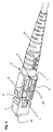
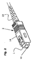
図1は、本発明によるコネクタ2,3用の内側ハウジング1の構造と機能形態を示している。この内側ハウジング1は、調製された光ファイバケーブル5をそのフェルール6とともに側方からハウジングへ挿入することを可能にする、側方の切欠き4を有している。内側ハウジング1の図示した実施形態は、条溝状の切欠き8を備える裏壁7を有している。この裏壁は、フェルール6をストッパ面に向かって押圧するばね部材、特に板ばね9を挿入することを可能にする。このことは、結合時に、光ファイバの端面11を対応する光ファイバの端面に向かって押圧することを可能にする。このように組み付けられた光ファイバケーブル5を保護するために、本発明の内側ハウジング1は、裏壁7から外側に突出する継ぎ手部(Ansatzstuck)12を有しており、この継ぎ手部に、周知の種類の座屈防止具13を外嵌することができる。これに加えて、この内側ハウジング1は少なくとも一方の端面に、特に側方の切欠き4と向かい合う端面に、内側ハウジング1に固定されたフェルール6を非破壊で取り外すための少なくとも1つの開口部(図示せず)を有している。特にこの開口部は、ドライバーまたはこれに類似する工具で、フェルール6を光ファイバケーブル5とともに内側ハウジング1から押し出すことを可能にするためのものである。板ばね9に代えて、コイルばねまたはその他の弾性部材をばね部材9として同様に良好に使用できるのは言うまでもない。このような装備をもつ内側ハウジング1を、図2から明らかなプッシュプル型コネクタ2を形成するために、周知の方法で外側ハウジング14に差し込むことができる。図2は、今日すでに使用されている、POFフェルールと、規格化された差込口形状とを備えるSC型コネクタの外側輪郭を示している。
FIG. 1 shows the structure and functional configuration of an
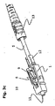
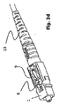
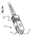
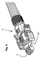
図3a〜3eは、本発明による内側ハウジング1を用いたコネクタ2の組み付け方を明らかにしている。その際には、現場で裁断された光ファイバケーブル5に座屈防止具13を外嵌し、このケーブル5の端部を絶縁除去する。そして露出した光ファイバを、フェルール6へ挿入することができる。フェルール6を光ファイバーケーブル5とともに固定するには、特に、たとえばEP−A−1457797から公知となっているような、ねじ固定可能なフェルール6が適している。図3bから明らかなように、このようにして調製された光ファイバケーブル5をフェルール6とともに、本発明による内側ハウジング1へ側方から挿入する。図3cからは、挿入されたフェルール6が板ばね9によってストッパ面10に押圧される様子が明らかである。このばね部材は、内側ハウジング1とその内部にあるフェルール6との間の軸方向の移動を可能とする。光ファイバケーブル5をよりいっそう保護するために、座屈防止具13を継ぎ手部12に外嵌する。図3dは、本発明による内側ハウジング1を組み付け状態で示しており、すなわち、調製された光ファイバケーブル5および外嵌された座屈防止具13とともに示している。そして、このように装着された内側ハウジング1を、図3eから明らかなように、最後のステップで、標準化された外側ハウジング2へ、特にSC−RJ型デュプレックス(Duplex)コネクタ(図4参照)へ取り付けることができる。
Figures 3a to 3e reveal how to assemble the
本発明による内側ハウジング1は、家庭用SC型コネクタ2(図2参照)の製作に適しており、産業用のSC−RJ型コネクタ(図4参照)の製作にも同様に適している。本発明の構成は、さまざまな型式の光ファイバケーブル5を使用することを可能にし、特に、段差または勾配インデックス(Stufen-order Gradientenindex)を有する、シングルモードまたはマルチモードのガラスファイバまたはプラスチックファイバ(POF)を使用することができる。
The
本発明の利点は当業者には容易に明らかであり、特に、現地調製が可能であること、個々のコンポーネントがモジュール形式であること、非破壊で取り外せることなどに見ることができる。特に、組み付けや取り外しのために特別な工具や補助手段が必要なく、このことは、不慣れな者にも簡単かつ迅速な作業を可能にする。取り外しを非破壊で行うことができ、すなわち、個別部品を再利用可能である。挿入されたフェルールは、結合時に、中央部または結合部に配設されるので、光導体をセンタリングするための高いコストのかかる技術的方策を省略することができる。1組の板ばねをばね部材として使用するのが格別に好ましいことが判明している。このような板ばねは工場ですでに予備組み付けすることができ、したがって、「現地」で使用する構成部品を必要最低限に抑えることができるからである。 The advantages of the present invention are readily apparent to those skilled in the art and can be seen in particular in that it can be prepared in-situ, that the individual components are modular, and can be removed non-destructively. In particular, no special tools or auxiliary means are required for assembly and removal, which makes it possible for unskilled persons to work easily and quickly. The removal can be performed non-destructively, i.e. the individual parts can be reused. Since the inserted ferrule is disposed at the center or the coupling part at the time of coupling, it is possible to omit a costly technical measure for centering the light guide. It has been found that it is particularly preferable to use a set of leaf springs as spring members. This is because such leaf springs can already be pre-assembled at the factory, so that the components used "in the field" can be minimized.
上に詳しく説明した実施例を、側方からの組み付けが可能という技術思想から離れることなく、(特にSC,STまたはSMAの差込幾何形状に合わせて)別様に構成したり寸法決めできることは当然である。 The embodiment described in detail above can be configured and dimensioned differently (particularly in accordance with the SC, ST or SMA plug-in geometry) without departing from the technical idea that it can be assembled from the side. Of course.
Claims (8)
Applications Claiming Priority (2)
| Application Number | Priority Date | Filing Date | Title |
|---|---|---|---|
| CH15642004 | 2004-09-24 | ||
| PCT/CH2005/000508 WO2006032153A1 (en) | 2004-09-24 | 2005-08-30 | Inner housing for a fibre-optic plug connector |
Publications (1)
| Publication Number | Publication Date |
|---|---|
| JP2008513844A true JP2008513844A (en) | 2008-05-01 |
Family
ID=34974218
Family Applications (1)
| Application Number | Title | Priority Date | Filing Date |
|---|---|---|---|
| JP2007532744A Pending JP2008513844A (en) | 2004-09-24 | 2005-08-30 | Inner housing for optical fiber connector |
Country Status (7)
| Country | Link |
|---|---|
| US (1) | US20070211998A1 (en) |
| EP (1) | EP1792217A1 (en) |
| JP (1) | JP2008513844A (en) |
| KR (2) | KR20070047360A (en) |
| CN (1) | CN100580492C (en) |
| TW (1) | TW200610995A (en) |
| WO (1) | WO2006032153A1 (en) |
Cited By (2)
| Publication number | Priority date | Publication date | Assignee | Title |
|---|---|---|---|---|
| WO2012056908A1 (en) * | 2010-10-28 | 2012-05-03 | 矢崎総業株式会社 | Optical connector |
| JP2014235371A (en) * | 2013-06-04 | 2014-12-15 | 矢崎総業株式会社 | Optical connector |
Families Citing this family (14)
| Publication number | Priority date | Publication date | Assignee | Title |
|---|---|---|---|---|
| EP2012152A1 (en) * | 2007-07-06 | 2009-01-07 | Ridgemount Technologies Limited | Optical Ferrule Retainer |
| US8152384B2 (en) | 2009-10-15 | 2012-04-10 | Corning Cable Systems Llc | Push-pull fiber optic connectors and methods for making the same |
| WO2012037727A1 (en) * | 2010-09-21 | 2012-03-29 | 深圳日海通讯技术股份有限公司 | Optical fiber connector and assembly methods thereof |
| US8348686B1 (en) * | 2011-10-11 | 2013-01-08 | Li-Ping Huang | Plug security structure for electrical connector |
| WO2013077969A1 (en) | 2011-11-23 | 2013-05-30 | Adc Telecommunications, Inc. | Multi-fiber fiber optic connector |
| CN102540356A (en) * | 2012-02-02 | 2012-07-04 | 安费诺光纤技术(深圳)有限公司 | Multi-fiber push on (MPO) rear base body |
| RU2014138122A (en) | 2012-02-20 | 2016-04-10 | Адс Телекоммьюникейшнз, Инк. | FIBER OPTICAL CONNECTOR, FIBER OPTICAL CONNECTOR AND CABLE ASSEMBLY AND METHODS FOR THEIR MANUFACTURE |
| WO2013151583A1 (en) * | 2012-04-05 | 2013-10-10 | Nanoprecision Products, Inc. | Ferrule for optical fiber connector having a compliant structure for clamping alignment pins |
| US9022667B2 (en) * | 2012-11-02 | 2015-05-05 | Tyco Electronics Corporation | Pin and socket terminus assemblies for terminating optical cables |
| EP2759859B1 (en) * | 2013-01-29 | 2018-05-16 | Tyco Electronics Nederland B.V. | Guiding support and kit for terminating a transmission cable |
| DE102013102023C5 (en) | 2013-03-01 | 2022-08-18 | Harting Electric Stiftung & Co. Kg | Optical module for modular industrial connectors |
| US9720185B2 (en) | 2014-05-23 | 2017-08-01 | Commscope Technologies Llc | Systems and method for processing optical cable assemblies |
| US20170307828A1 (en) * | 2014-12-01 | 2017-10-26 | Commscope Asia Holdings B.V. | Hybrid electrical optical connector with spring-loaded electrical contacts at a contact face |
| USD970447S1 (en) * | 2019-10-24 | 2022-11-22 | 3P Design | Optical fiber connector |
Citations (9)
| Publication number | Priority date | Publication date | Assignee | Title |
|---|---|---|---|---|
| JPH05188240A (en) * | 1992-01-10 | 1993-07-30 | Nec Corp | Optical connector terminal structure |
| JPH05313041A (en) * | 1992-05-01 | 1993-11-26 | Furukawa Electric Co Ltd:The | Individual connector unit |
| JP2562577Y2 (en) * | 1991-01-31 | 1998-02-10 | 日本電気株式会社 | Optical connector |
| JPH11237527A (en) * | 1998-02-24 | 1999-08-31 | Oki Electric Ind Co Ltd | Optical connector |
| JPH11287929A (en) * | 1998-04-03 | 1999-10-19 | Sanwa Denki Kogyo Co Ltd | Optical connector plug |
| JPH11512196A (en) * | 1995-09-01 | 1999-10-19 | シーメンス アクチエンゲゼルシヤフト | Optical plug connector |
| JP2001301521A (en) * | 2000-04-20 | 2001-10-31 | Daihatsu Motor Co Ltd | Mounting structure for lamp |
| JP2002258107A (en) * | 2001-01-17 | 2002-09-11 | Harting Automotive Gmbh & Co Kg | Optical connector |
| JP2003091118A (en) * | 2001-09-18 | 2003-03-28 | Ricoh Co Ltd | Image forming apparatus |
Family Cites Families (8)
| Publication number | Priority date | Publication date | Assignee | Title |
|---|---|---|---|---|
| EP0375168B1 (en) * | 1988-12-21 | 1993-07-14 | The Whitaker Corporation | Optical connector |
| US5311609A (en) * | 1992-10-29 | 1994-05-10 | Hirose Electric Co., Ltd. | Optical fiber connector |
| US5287425A (en) * | 1993-02-26 | 1994-02-15 | Foxconn International, Inc. | Optical fiber SC type connector assembly with partly pre-assembled components |
| DE4423711C1 (en) * | 1994-06-24 | 1996-01-04 | Siemens Ag | Compact optical fibre plug |
| US5481634A (en) * | 1994-06-24 | 1996-01-02 | At&T Corp. | Connector for optical fiber |
| DE19913449A1 (en) * | 1999-03-25 | 2000-09-28 | Kostal Leopold Gmbh & Co Kg | Optical plug connector for connecting two optical waveguides to one another or an optical waveguide to another with plug-socket connection, using spring element around waveguide in recess allowing longitudinal extension of spring |
| EP1254387B1 (en) * | 2000-02-11 | 2006-08-02 | Huber & Suhner Ag | Optical connector for simultaneously connecting a plurality of fiber optical cables and adapter for said connector |
| DE20303848U1 (en) * | 2003-03-11 | 2003-06-26 | Reichle & De Massari Ag Wetzik | ferrule |
-
2005
- 2005-07-19 TW TW094124332A patent/TW200610995A/en not_active IP Right Cessation
- 2005-08-30 KR KR1020077006781A patent/KR20070047360A/en not_active Application Discontinuation
- 2005-08-30 CN CN200580032514A patent/CN100580492C/en not_active Expired - Fee Related
- 2005-08-30 US US11/575,894 patent/US20070211998A1/en not_active Abandoned
- 2005-08-30 KR KR1020097005635A patent/KR20090032149A/en not_active Application Discontinuation
- 2005-08-30 EP EP05773360A patent/EP1792217A1/en not_active Withdrawn
- 2005-08-30 WO PCT/CH2005/000508 patent/WO2006032153A1/en active Application Filing
- 2005-08-30 JP JP2007532744A patent/JP2008513844A/en active Pending
Patent Citations (9)
| Publication number | Priority date | Publication date | Assignee | Title |
|---|---|---|---|---|
| JP2562577Y2 (en) * | 1991-01-31 | 1998-02-10 | 日本電気株式会社 | Optical connector |
| JPH05188240A (en) * | 1992-01-10 | 1993-07-30 | Nec Corp | Optical connector terminal structure |
| JPH05313041A (en) * | 1992-05-01 | 1993-11-26 | Furukawa Electric Co Ltd:The | Individual connector unit |
| JPH11512196A (en) * | 1995-09-01 | 1999-10-19 | シーメンス アクチエンゲゼルシヤフト | Optical plug connector |
| JPH11237527A (en) * | 1998-02-24 | 1999-08-31 | Oki Electric Ind Co Ltd | Optical connector |
| JPH11287929A (en) * | 1998-04-03 | 1999-10-19 | Sanwa Denki Kogyo Co Ltd | Optical connector plug |
| JP2001301521A (en) * | 2000-04-20 | 2001-10-31 | Daihatsu Motor Co Ltd | Mounting structure for lamp |
| JP2002258107A (en) * | 2001-01-17 | 2002-09-11 | Harting Automotive Gmbh & Co Kg | Optical connector |
| JP2003091118A (en) * | 2001-09-18 | 2003-03-28 | Ricoh Co Ltd | Image forming apparatus |
Cited By (2)
| Publication number | Priority date | Publication date | Assignee | Title |
|---|---|---|---|---|
| WO2012056908A1 (en) * | 2010-10-28 | 2012-05-03 | 矢崎総業株式会社 | Optical connector |
| JP2014235371A (en) * | 2013-06-04 | 2014-12-15 | 矢崎総業株式会社 | Optical connector |
Also Published As
| Publication number | Publication date |
|---|---|
| EP1792217A1 (en) | 2007-06-06 |
| TW200610995A (en) | 2006-04-01 |
| US20070211998A1 (en) | 2007-09-13 |
| WO2006032153A1 (en) | 2006-03-30 |
| CN101031833A (en) | 2007-09-05 |
| KR20070047360A (en) | 2007-05-04 |
| KR20090032149A (en) | 2009-03-31 |
| CN100580492C (en) | 2010-01-13 |
| TWI304138B (en) | 2008-12-11 |
Similar Documents
| Publication | Publication Date | Title |
|---|---|---|
| JP2008513844A (en) | Inner housing for optical fiber connector | |
| US7534051B2 (en) | Optical fiber connector, optical fiber connecting method, and connector converter | |
| US8297850B2 (en) | Optical connector, and method of assembling optical connector | |
| JP5034650B2 (en) | Optical fiber connector and optical cable | |
| JP5497332B2 (en) | Optical connector | |
| KR20070056040A (en) | Optical connector and optical fiber connecting system | |
| JP2007121859A (en) | Optical connector receptacle and optical connector | |
| JP5702884B1 (en) | Optical connector plug | |
| EP3474052A1 (en) | Optical connector and optical connection structure | |
| JP2011034001A (en) | Optical connector and optical connector-connecting structure | |
| JP2012037624A (en) | Optical connector and optical connector assembly tool | |
| JP6383617B2 (en) | Optical fiber connection structure, optical fiber connector | |
| JP4976145B2 (en) | Optical connector | |
| JP2008299348A (en) | Optical connector adaptor and optical connector | |
| JP4387732B2 (en) | Optical connector | |
| JP4192751B2 (en) | Optical fiber connector and optical fiber connection method | |
| JPH1164683A (en) | Optical connector | |
| JP2005128327A (en) | Optical connector | |
| JPH11160579A (en) | Optical connector | |
| JP4295608B2 (en) | Field assembly optical connector | |
| JP2005084140A (en) | Optical connector | |
| JP4192748B2 (en) | Optical fiber connecting member and optical fiber connecting method | |
| JP4163077B2 (en) | Optical connector | |
| WO2022049792A1 (en) | Optical connector and method of manufacturing optical connector | |
| JP2010096981A (en) | Optical fiber connector and assembly method of the same |
Legal Events
| Date | Code | Title | Description |
|---|---|---|---|
| A977 | Report on retrieval |
Free format text: JAPANESE INTERMEDIATE CODE: A971007 Effective date: 20091210 |
|
| A131 | Notification of reasons for refusal |
Free format text: JAPANESE INTERMEDIATE CODE: A131 Effective date: 20100119 |
|
| A601 | Written request for extension of time |
Free format text: JAPANESE INTERMEDIATE CODE: A601 Effective date: 20100419 |
|
| A602 | Written permission of extension of time |
Free format text: JAPANESE INTERMEDIATE CODE: A602 Effective date: 20100426 |
|
| A521 | Written amendment |
Free format text: JAPANESE INTERMEDIATE CODE: A523 Effective date: 20100517 |
|
| A131 | Notification of reasons for refusal |
Free format text: JAPANESE INTERMEDIATE CODE: A131 Effective date: 20100727 |
|
| A601 | Written request for extension of time |
Free format text: JAPANESE INTERMEDIATE CODE: A601 Effective date: 20101027 |
|
| A602 | Written permission of extension of time |
Free format text: JAPANESE INTERMEDIATE CODE: A602 Effective date: 20101104 |
|
| A601 | Written request for extension of time |
Free format text: JAPANESE INTERMEDIATE CODE: A601 Effective date: 20101129 |
|
| A602 | Written permission of extension of time |
Free format text: JAPANESE INTERMEDIATE CODE: A602 Effective date: 20101214 |
|
| A02 | Decision of refusal |
Free format text: JAPANESE INTERMEDIATE CODE: A02 Effective date: 20110308 |