JP2008511640A - Optimized liquid phase oxidation - Google Patents
Optimized liquid phase oxidation Download PDFInfo
- Publication number
- JP2008511640A JP2008511640A JP2007530198A JP2007530198A JP2008511640A JP 2008511640 A JP2008511640 A JP 2008511640A JP 2007530198 A JP2007530198 A JP 2007530198A JP 2007530198 A JP2007530198 A JP 2007530198A JP 2008511640 A JP2008511640 A JP 2008511640A
- Authority
- JP
- Japan
- Prior art keywords
- reaction medium
- reactor
- oxidation
- oxygen
- reaction
- Prior art date
- Legal status (The legal status is an assumption and is not a legal conclusion. Google has not performed a legal analysis and makes no representation as to the accuracy of the status listed.)
- Pending
Links
Images


Classifications
-
- C—CHEMISTRY; METALLURGY
- C07—ORGANIC CHEMISTRY
- C07C—ACYCLIC OR CARBOCYCLIC COMPOUNDS
- C07C51/00—Preparation of carboxylic acids or their salts, halides or anhydrides
- C07C51/16—Preparation of carboxylic acids or their salts, halides or anhydrides by oxidation
- C07C51/21—Preparation of carboxylic acids or their salts, halides or anhydrides by oxidation with molecular oxygen
- C07C51/23—Preparation of carboxylic acids or their salts, halides or anhydrides by oxidation with molecular oxygen of oxygen-containing groups to carboxyl groups
- C07C51/235—Preparation of carboxylic acids or their salts, halides or anhydrides by oxidation with molecular oxygen of oxygen-containing groups to carboxyl groups of —CHO groups or primary alcohol groups
-
- C—CHEMISTRY; METALLURGY
- C07—ORGANIC CHEMISTRY
- C07C—ACYCLIC OR CARBOCYCLIC COMPOUNDS
- C07C51/00—Preparation of carboxylic acids or their salts, halides or anhydrides
- C07C51/16—Preparation of carboxylic acids or their salts, halides or anhydrides by oxidation
- C07C51/21—Preparation of carboxylic acids or their salts, halides or anhydrides by oxidation with molecular oxygen
- C07C51/255—Preparation of carboxylic acids or their salts, halides or anhydrides by oxidation with molecular oxygen of compounds containing six-membered aromatic rings without ring-splitting
- C07C51/265—Preparation of carboxylic acids or their salts, halides or anhydrides by oxidation with molecular oxygen of compounds containing six-membered aromatic rings without ring-splitting having alkyl side chains which are oxidised to carboxyl groups
-
- C—CHEMISTRY; METALLURGY
- C07—ORGANIC CHEMISTRY
- C07C—ACYCLIC OR CARBOCYCLIC COMPOUNDS
- C07C51/00—Preparation of carboxylic acids or their salts, halides or anhydrides
- C07C51/16—Preparation of carboxylic acids or their salts, halides or anhydrides by oxidation
- C07C51/21—Preparation of carboxylic acids or their salts, halides or anhydrides by oxidation with molecular oxygen
-
- C—CHEMISTRY; METALLURGY
- C07—ORGANIC CHEMISTRY
- C07C—ACYCLIC OR CARBOCYCLIC COMPOUNDS
- C07C51/00—Preparation of carboxylic acids or their salts, halides or anhydrides
- C07C51/42—Separation; Purification; Stabilisation; Use of additives
- C07C51/487—Separation; Purification; Stabilisation; Use of additives by treatment giving rise to chemical modification
-
- C—CHEMISTRY; METALLURGY
- C07—ORGANIC CHEMISTRY
- C07C—ACYCLIC OR CARBOCYCLIC COMPOUNDS
- C07C63/00—Compounds having carboxyl groups bound to a carbon atoms of six-membered aromatic rings
- C07C63/14—Monocyclic dicarboxylic acids
- C07C63/15—Monocyclic dicarboxylic acids all carboxyl groups bound to carbon atoms of the six-membered aromatic ring
- C07C63/26—1,4 - Benzenedicarboxylic acid
-
- Y—GENERAL TAGGING OF NEW TECHNOLOGICAL DEVELOPMENTS; GENERAL TAGGING OF CROSS-SECTIONAL TECHNOLOGIES SPANNING OVER SEVERAL SECTIONS OF THE IPC; TECHNICAL SUBJECTS COVERED BY FORMER USPC CROSS-REFERENCE ART COLLECTIONS [XRACs] AND DIGESTS
- Y02—TECHNOLOGIES OR APPLICATIONS FOR MITIGATION OR ADAPTATION AGAINST CLIMATE CHANGE
- Y02P—CLIMATE CHANGE MITIGATION TECHNOLOGIES IN THE PRODUCTION OR PROCESSING OF GOODS
- Y02P20/00—Technologies relating to chemical industry
- Y02P20/50—Improvements relating to the production of bulk chemicals
- Y02P20/52—Improvements relating to the production of bulk chemicals using catalysts, e.g. selective catalysts
Abstract
被酸化性化合物の液相酸化をより効率的で且つ経済的に実施するための最適化方法及び装置が開示される。このような液相酸化は、比較的低温で高効率の反応を実現する気泡塔型反応器中で実施される。被酸化性化合物がp−キシレンであり且つ酸化反応からの生成物が粗製テレフタル酸(CTA)である場合には、このようなCTA生成物は、CTAが従来の高温酸化方法によって生成されたならば使用されたであろう方法よりも経済的な手法によって精製及び分離することができる。 Disclosed are optimization methods and apparatus for performing liquid phase oxidation of oxidizable compounds more efficiently and economically. Such liquid phase oxidation is carried out in a bubble column reactor that realizes a highly efficient reaction at a relatively low temperature. When the oxidizable compound is p-xylene and the product from the oxidation reaction is crude terephthalic acid (CTA), such a CTA product can be obtained if CTA is produced by a conventional high temperature oxidation method. It can be purified and separated by a more economical technique than would have been used.
Description
本発明は一般に芳香族化合物の液相接触酸化方法に関する。本発明の一態様は、ジアルキル芳香族化合物(例えばp−キシレン)の部分酸化による、その後に精製及び分離に供されることができる粗製芳香族ジカルボン酸(例えば粗製テレフタル酸)の製造に関する。本発明の別の態様は、より効率的且つ経済的な液相酸化方法を実現する、改良された気泡塔型反応器に関する。 The present invention relates generally to a liquid phase catalytic oxidation process for aromatic compounds. One aspect of the present invention relates to the production of crude aromatic dicarboxylic acids (eg, crude terephthalic acid) that can be subsequently subjected to purification and separation by partial oxidation of dialkyl aromatic compounds (eg, p-xylene). Another aspect of the invention relates to an improved bubble column reactor that provides a more efficient and economical liquid phase oxidation process.
液相酸化反応は従来の種々の既存の商業的方法において用いられている。例えば、液相酸化は、アルデヒドの酸への酸化(例えばプロピオンアルデヒドのプロピオン酸への酸化)、シクロヘキサンのアジピン酸への酸化及びアルキル芳香族炭化水素のアルコール、酸又は二酸への酸化のために現在使用されている。後者のカテゴリ(アルキル芳香族炭化水素の酸化)における特に重要な商業的酸化方法はp−キシレンのテレフタル酸への液相接触部分酸化である。テレフタル酸は種々の用途を有する重要な化合物である。テレフタル酸の主な用途はポリエチレンテレフタレート(PET)の製造における供給原料としての使用である。PETはボトル、繊維及びパッケージのような製品を製造するために世界中で多量に用いられている公知のプラスチックである。 Liquid phase oxidation reactions are used in various existing commercial processes. For example, liquid phase oxidation is due to oxidation of aldehydes to acids (eg, oxidation of propionaldehyde to propionic acid), oxidation of cyclohexane to adipic acid, and oxidation of alkyl aromatic hydrocarbons to alcohols, acids or diacids. Is currently used. A particularly important commercial oxidation process in the latter category (oxidation of alkyl aromatic hydrocarbons) is liquid phase catalytic partial oxidation of p-xylene to terephthalic acid. Terephthalic acid is an important compound with various uses. The primary use of terephthalic acid is as a feedstock in the production of polyethylene terephthalate (PET). PET is a known plastic that is used in large quantities throughout the world to produce products such as bottles, fibers and packages.
p−キシレンのテレフタル酸への部分酸化を含む典型的な液相酸化方法においては、液相供給流及び気相酸化剤流を反応器中に導入し、反応器中に多相反応媒体を形成する。反応器中に導入される液相供給流は少なくとも1種の被酸化性(oxidizable)有機化合物(例えばp−キシレン)を含み、一方気相酸化剤流は分子状酸素を含む。反応器中に気体として導入される分子状酸素の少なくとも一部は、反応媒体の液相中に溶解して、液相反応に酸素利用可能性を提供する。多相反応媒体の液相が不充分な濃度の分子状酸素を含む場合には(即ち、反応媒体の或る部分が「酸素欠乏状態(oxygen-starved)である」場合には)、不所望な副反応が不純物を生じるおそれがあり且つ/又は目的とする反応が遅くなる可能性がある。反応媒体の液相に含まれる被酸化性化合物が少なすぎる場合には、反応速度は不所望に遅くなる可能性がある。更に、反応媒体の液相が過剰な濃度の被酸化性化合物を含む場合には、更なる不所望な副反応が不純物を生じるおそれがある。 In a typical liquid phase oxidation process involving partial oxidation of p-xylene to terephthalic acid, a liquid phase feed stream and a gas phase oxidant stream are introduced into the reactor to form a multiphase reaction medium in the reactor. To do. The liquid phase feed stream introduced into the reactor contains at least one oxidizable organic compound (eg, p-xylene), while the gas phase oxidant stream contains molecular oxygen. At least a portion of the molecular oxygen introduced as a gas into the reactor dissolves in the liquid phase of the reaction medium, providing oxygen availability to the liquid phase reaction. Undesirable if the liquid phase of the multiphase reaction medium contains an insufficient concentration of molecular oxygen (ie if some part of the reaction medium is “oxygen-starved”) Side reactions may cause impurities and / or the intended reaction may be slow. If too little oxidizable compound is contained in the liquid phase of the reaction medium, the reaction rate can be undesirably slowed. Furthermore, if the liquid phase of the reaction medium contains an excessive concentration of oxidizable compound, further unwanted side reactions may result in impurities.
従来の液相酸化反応器には、中に含まれる多相反応媒体を混合するための撹拌手段が装着される。反応媒体の撹拌は、反応媒体の液相への分子状酸素の溶解を促進し、反応媒体の液相中に比較的均一な濃度の溶存酸素を保持し、且つ反応媒体の液相中に比較的均一な濃度の被酸化性有機化合物を保持するために提供される。 The conventional liquid phase oxidation reactor is equipped with a stirring means for mixing the multiphase reaction medium contained therein. Agitation of the reaction medium facilitates the dissolution of molecular oxygen in the liquid phase of the reaction medium, maintains a relatively uniform concentration of dissolved oxygen in the liquid phase of the reaction medium, and compares in the liquid phase of the reaction medium. To maintain a uniform concentration of oxidizable organic compounds.
液相酸化を受ける反応媒体の撹拌は、例えば連続撹拌槽型反応器(CSTR)のような容器中で機械的撹拌手段によって提供されることが多い。CSTRは反応媒体の充分な混合を提供するが、多くの欠点を有する。例えば、CSTRは、高価なモーター、流体シールベアリング及び駆動軸を必要とするため、比較的高い資本コストがかかる。更に、従来のCSTRの回転及び/又は振動する機械部品は定期保守を必要とする。このような保守に付随する労働力及び運転停止が、CSTRの運転コストを増加させる。しかし、定期保守を行ったとしても、CSTRに使用される機械的撹拌システムは、機械的に故障しやすく、比較的短い期間で交換が必要となる可能性がある。 Agitation of the reaction medium undergoing liquid phase oxidation is often provided by mechanical stirring means in a vessel such as a continuous stirred tank reactor (CSTR). Although CSTR provides sufficient mixing of the reaction medium, it has a number of drawbacks. For example, CSTR requires a relatively high capital cost because it requires expensive motors, fluid seal bearings and drive shafts. Furthermore, conventional CSTR rotating and / or vibrating mechanical parts require regular maintenance. The labor and outages associated with such maintenance increase CSTR operating costs. However, even with regular maintenance, the mechanical agitation system used for CSTR is prone to mechanical failure and may need to be replaced in a relatively short period of time.
気泡塔型反応器(bubble column reactor)は、CSTR及び他の機械的撹拌酸化反応器の魅力的な代替手段を提供する。気泡塔型反応器は、高価で信頼性の低い機械的装置を必要とせずに、反応媒体の撹拌を実現する。気泡塔型反応器は、典型的には、反応媒体を内部に含む細長い直立反応ゾーンを含む。反応ゾーン中における反応媒体の撹拌は主に反応媒体の液体相を通って上昇する気泡の自然浮揚性(natural buoyance)によってもたらされる。気泡塔型反応器中に生じるこの自然浮揚性撹拌は、機械的撹拌反応器に比較して資本コスト及び維持費を減少させる。更に、気泡塔型反応器には動く機械部品が実質的に関係しないため、機械的撹拌反応器よりも機械的に故障しにくい酸化システムが提供される。 Bubble column reactors provide an attractive alternative to CSTR and other mechanically stirred oxidation reactors. Bubble column reactors provide agitation of the reaction medium without the need for expensive and unreliable mechanical equipment. Bubble column reactors typically include an elongated upright reaction zone containing a reaction medium therein. Agitation of the reaction medium in the reaction zone is mainly provided by the natural buoyance of the bubbles rising through the liquid phase of the reaction medium. This natural buoyant agitation that occurs in the bubble column reactor reduces capital and maintenance costs compared to a mechanically stirred reactor. In addition, since bubble column reactors are substantially free of moving mechanical components, an oxidation system is provided that is less prone to mechanical failure than mechanically stirred reactors.
p−キシレンの液相部分酸化を従来の酸化反応器(CSTR又は気泡塔)中で実施する場合には、反応器から回収された生成物は典型的には粗製テレフタル酸(CTA)及び母液を含むスラリーである。CTAは比較的高レベルの不純物(例えば4−カルボキシベンズアルデヒド、p−トルイル酸、フルオレノン類及び他の色素体)を含むので、PET製造用の供給原料としては不適当である。従って、従来の酸化反応器において製造されたCTAは典型的にはPETの製造に適した精製テレフタル酸(PTA)にCTAを転化する精製プロセスに供される。 When liquid phase partial oxidation of p-xylene is carried out in a conventional oxidation reactor (CSTR or bubble column), the product recovered from the reactor typically contains crude terephthalic acid (CTA) and mother liquor. It is a slurry containing. CTA contains relatively high levels of impurities (eg, 4-carboxybenzaldehyde, p-toluic acid, fluorenones, and other chromophores), making it unsuitable as a feedstock for PET production. Thus, CTA produced in conventional oxidation reactors is typically subjected to a purification process that converts CTA to purified terephthalic acid (PTA) suitable for the production of PET.
CTAをPTAに転化するための1つの典型的な精製方法は以下の工程を含む:(1)CTA含有スラリーの母液を水で置換し;(2)CTA/水スラリーを加熱して、CTAを水中に溶解させ;(3)CTA/水溶液を接触水素化して、不純物をより望ましく且つ/又は分離し易い化合物に転化し;(4)得られたPTAを水素化溶液から多数の結晶化工程によって沈殿させ、そして(5)結晶化したPTAを残りの液体から分離する。この型の従来の精製方法は効果的ではあるが、非常に高価である可能性がある。従来のCTA精製方法の高いコストの一因となる個々の要因には、例えば、水中へのCTAの溶解を促進するのに必要な熱エネルギー、水素化に必要な触媒、水素化に必要な水素流、一部のテレフタル酸の水素化によって引き起こされる収率損失及び多段結晶化に必要な多数の容器がある。従って、水中への熱促進溶解、水素化及び/又は多段結晶化を必要とせずに、精製することができるCTA製品を提供できれば望ましいであろう。 One typical purification method for converting CTA to PTA includes the following steps: (1) replacing the mother liquor of the CTA-containing slurry with water; (2) heating the CTA / water slurry to convert the CTA. Dissolved in water; (3) catalytic hydrogenation of the CTA / water solution to convert impurities to more desirable and / or separable compounds; (4) the resulting PTA from the hydrogenation solution by multiple crystallization steps. Precipitate and (5) separate the crystallized PTA from the remaining liquid. Although this type of conventional purification method is effective, it can be very expensive. Individual factors that contribute to the high cost of conventional CTA purification methods include, for example, thermal energy required to promote dissolution of CTA in water, catalyst required for hydrogenation, and hydrogen required for hydrogenation. There are a number of vessels required for the flow, yield loss caused by hydrogenation of some terephthalic acid and multistage crystallization. Accordingly, it would be desirable to provide a CTA product that can be purified without the need for thermally enhanced dissolution in water, hydrogenation and / or multi-stage crystallization.
従って、本発明の1つの目的は、より効率的で且つ経済的な液相酸化反応器及び方法を提供することにある。 Accordingly, one object of the present invention is to provide a more efficient and economical liquid phase oxidation reactor and method.
本発明の別の目的は、p−キシレンのテレフタル酸への液相接触部分酸化のためのより効率的で且つ経済的な反応器及び方法を提供することにある。 Another object of the present invention is to provide a more efficient and economical reactor and process for liquid phase catalytic partial oxidation of p-xylene to terephthalic acid.
本発明の更に別の目的は、改良された液相酸化反応を促進すると共に不純物の形成を減少させる気泡塔型反応器を提供することにある。 Yet another object of the present invention is to provide a bubble column reactor that promotes an improved liquid phase oxidation reaction and reduces the formation of impurities.
本発明の更に別の目的は、p−キシレンの液相酸化による粗製テレフタル酸(CTA)の生成とそれに続くCTAのPTAへの精製によって純粋なテレフタル酸(PTA)を製造するための、より効率的で且つ経済的なシステムを提供することにある。 Yet another object of the present invention is more efficient for producing pure terephthalic acid (PTA) by the production of crude terephthalic acid (CTA) by liquid phase oxidation of p-xylene and subsequent purification of CTA to PTA. The objective is to provide an economical and economical system.
本発明の更に別の目的は、p−キシレンを酸化し、そしてCTAの水への熱促進溶解、溶解CTAの水素化及び/又は水素化PTAの多段結晶化を必要とせずに、精製することができるCTA製品を製造するための気泡塔型反応器を提供することにある。 Yet another object of the present invention is to oxidize and purify p-xylene without the need for heat enhanced dissolution of CTA in water, hydrogenation of dissolved CTA and / or multistage crystallization of hydrogenated PTA. It is an object of the present invention to provide a bubble column reactor for producing a CTA product that can be used.
添付した「特許請求の範囲」において規定される本発明の範囲は、前記の目的の全てを実現できる方法又は装置に限定するのではないことに留意されたい。むしろ、特許請求の範囲に記載された本発明の範囲は、前記目的の全て又はいずれかを達成しない種々の系を包含できる。本発明のその他の目的及び利点は、以下の詳細な説明及び関連した図面を見れば、当業者により明白になるであろう。 It should be noted that the scope of the present invention as defined in the appended claims is not limited to methods or apparatus capable of achieving all of the above objects. Rather, the scope of the present invention as set forth in the claims can encompass various systems that do not achieve all or any of the above objects. Other objects and advantages of the present invention will become apparent to those skilled in the art from the following detailed description and associated drawings.
本発明の一実施態様は、1つ又はそれ以上の機械的撹拌反応器に含まれる多相反応媒体の液相中において被酸化性化合物を酸化させる方法に関し、前記反応媒体は、第1の酸素空時速度(酸素−STR)を有する第1の別個の20%連続容積と第2の酸素−STRを有する第2の別個の20%連続容積を含み、第1の酸素−STR対第2の酸素−STRの比は少なくとも約1.5:1である。 One embodiment of the present invention relates to a method of oxidizing an oxidizable compound in a liquid phase of a multiphase reaction medium contained in one or more mechanically stirred reactors, the reaction medium comprising a first oxygen A first separate 20% continuous volume having a space time velocity (oxygen-STR) and a second separate 20% continuous volume having a second oxygen-STR, wherein the first oxygen-STR vs. second The oxygen-STR ratio is at least about 1.5: 1.
本発明の別の実施態様は、以下の工程:(a)被酸化性化合物を含む供給流を第1の反応器の第1の反応ゾーン中に導入し(前記第1の反応ゾーンは最大直径(D)を有し、前記第1の反応ゾーンの少なくとも一部は第1の反応器の1つ又はそれ以上の直立側壁によって規定し、前記被酸化性化合物の少なくとも約25重量%は前記直立側壁から内側に少なくとも0.05Dの間隔の位置において第1反応ゾーンに入る);そして(b)1つ又はそれ以上の反応器中に含まれる多相反応媒体の液相中において前記被酸化性化合物の少なくとも一部を酸化させる(前記反応媒体の少なくとも一部が第1の反応器に含まれ、前記反応媒体が、第1の酸素空時速度(酸素−STR)を有する第1の別個の20%連続容積と第2の酸素−STRを有する第2の別個の20%連続容積を含み、第1の酸素−STR対第2の酸素−STRの比は少なくとも約1.5:1である)ことを含む方法に関する。 Another embodiment of the present invention provides the following steps: (a) introducing a feed stream comprising an oxidizable compound into the first reaction zone of the first reactor, said first reaction zone having a maximum diameter. (D), wherein at least a portion of the first reaction zone is defined by one or more upstanding sidewalls of the first reactor, and at least about 25% by weight of the oxidizable compound is upright. Enters the first reaction zone at a distance of at least 0.05D inward from the sidewalls); and (b) said oxidizable in the liquid phase of the multiphase reaction medium contained in one or more reactors Oxidizing at least a portion of the compound (at least a portion of the reaction medium is included in a first reactor, the reaction medium having a first separate oxygen space time rate (oxygen-STR)). With 20% continuous volume and second oxygen-STR Comprises a second distinct 20-percent continuous volume, the ratio of the first oxygen -STR pair second oxygen -STR at least about 1.5: said method comprising 1).
本発明の更に別の実施態様は、別々の上流酸化反応器及び下流酸化反応器に含まれる多相反応媒体の液相中で被酸化性化合物を酸化することを含む方法に関し、前記反応媒体の第1の部分は上流反応器に含まれ、前記反応媒体の第2の部分は下流反応器に含まれ、前記反応媒体の第1の部分は第1の容器平均酸素−STRを有し、前記反応媒体の第2の部分は第2の容器平均酸素−STRを有し、第1の容器平均酸素−STR対第2の容器平均酸素−STRの比は約2:1〜約25:1の範囲である。 Yet another embodiment of the present invention relates to a method comprising oxidizing an oxidizable compound in a liquid phase of a multiphase reaction medium contained in separate upstream and downstream oxidation reactors, The first part is contained in an upstream reactor, the second part of the reaction medium is contained in a downstream reactor, the first part of the reaction medium has a first vessel average oxygen -STR, The second portion of the reaction medium has a second vessel average oxygen-STR, wherein the ratio of the first vessel average oxygen-STR to the second vessel average oxygen-STR is about 2: 1 to about 25: 1. It is a range.
本発明の更に別の実施態様は、以下の工程:(a)被酸化性化合物を含む供給流を気泡塔型反応器の反応ゾーン中に導入し;(b)分子状酸素を含む酸化剤流を前記反応ゾーン中に導入し;そして(c)前記反応ゾーンに含まれる多相反応媒体の液相中で前記被酸化性化合物の少なくとも一部を酸化させることを含む方法に関し、前記反応媒体は最大幅(W)、最大高さ(H)及び少なくとも約3:1のH:W比を有し、分子状酸素の大部分は前記反応ゾーンの底部の約0.25W以内において前記反応ゾーンに入り、酸化は、前記反応ゾーンを等容積の30個の水平スライスに理論的に分割した(partitioned)場合に、O2−max水平スライスが30個全ての水平スライスの最大酸素濃度を有し且つO2−min水平スライスがO2−max水平スライスの上方に位置する全ての水平スライスの最小酸素濃度を有するように、実施し、前記酸素濃度を前記反応媒体の気相中で時間平均及び容積平均モル湿潤基準で測定し、(O2−max水平スライスの酸素濃度)対(O2−min水平スライスの酸素濃度)の比が少なくとも約2:1である。 Yet another embodiment of the present invention comprises the following steps: (a) introducing a feed stream comprising an oxidizable compound into the reaction zone of a bubble column reactor; (b) an oxidant stream comprising molecular oxygen. And (c) oxidizing at least a portion of the oxidizable compound in the liquid phase of the multiphase reaction medium contained in the reaction zone, the reaction medium comprising: It has a maximum width (W), maximum height (H) and a H: W ratio of at least about 3: 1, with most of the molecular oxygen entering the reaction zone within about 0.25 W at the bottom of the reaction zone. Entering and oxidizing the O 2 -max horizontal slice has the maximum oxygen concentration of all 30 horizontal slices when the reaction zone is theoretically partitioned into 30 horizontal slices of equal volume and O 2 -min horizontal slice is O 2 -ma To have a minimum oxygen concentration of all the horizontal slices located above the horizontal slices was performed, the oxygen concentration measured at the time the gas phase-averaged and volume-averaged molar wet basis of the reaction medium, (O 2 -max oxygen concentration) versus horizontal slices (O 2 -min horizontal slice of the oxygen concentration ratio) of at least about 2: 1.
本発明の更なる実施態様は、以下の工程:(a)p−キシレンを含む供給流を第1の気泡塔型反応器の反応ゾーン中に導入し(前記反応ゾーンは最大直径(D)を有し、反応ゾーンの少なくとも一部は気泡塔型反応器の1つ又はそれ以上の直立側壁によって規定し、被酸化性化合物の少なくとも約25重量%は前記側壁から内側に少なくとも0.05Dの間隔の位置において第1の反応ゾーンに入る);(b)前記気泡塔型反応器中に含まれる三相反応媒体の液相中においてp−キシレンの少なくとも一部を酸化させることによって粗製テレフタル酸を生成し[前記反応媒体は第1の酸素空時速度(酸素−STR)を有する第1の別個の20%連続容積と第2の酸素−STRを有する第2の別個の20%連続容積を含み、第1の酸素−STR対第2の酸素−STRの比が少なくとも約1.5:1である];そして(c)前記粗製テレフタル酸の少なくとも一部を二次酸化反応器中において酸化することによって、より純粋なテレフタル酸を生成させることを含む方法に関する。 A further embodiment of the present invention provides the following steps: (a) introducing a feed stream comprising p-xylene into the reaction zone of the first bubble column reactor, said reaction zone having a maximum diameter (D). And at least a portion of the reaction zone is defined by one or more upstanding sidewalls of the bubble column reactor, wherein at least about 25% by weight of the oxidizable compound is spaced at least 0.05D inward from the sidewalls. (B) the crude terephthalic acid is oxidized by oxidizing at least a portion of p-xylene in the liquid phase of the three-phase reaction medium contained in the bubble column reactor. [Wherein the reaction medium comprises a first separate 20% continuous volume having a first oxygen space velocity (oxygen-STR) and a second separate 20% continuous volume having a second oxygen-STR. , First oxygen-STR The second oxygen-STR ratio is at least about 1.5: 1]; and (c) purifying terephthalic acid more pure by oxidizing at least a portion of said crude terephthalic acid in a secondary oxidation reactor Is generated.
本発明の好ましい実施態様を、添付図面の図に関して以下に詳細に記載する。添付図面中において、
図1は、本発明の一実施態様に従って構築された酸化反応器の側面図であり、反応器中への供給流、酸化剤流及び還流の導入、反応器中における多相反応媒体の存在並びに反応器の頂部(top)及び底部(bottom)のそれぞれからの気体及びスラリーの回収を特に示し;
図2は、図3のライン2−2に沿った気泡塔型反応器の底部の拡大側断面図であり、反応器への酸化剤流の導入に使用される酸化剤スパージャーの位置及び構造を特に示し;
図3は、図2の酸化剤スパージャーの上面図であり、酸化剤スパージャー頂部の酸化剤用開口部を特に示し;
図4は、図2の酸化剤スパージャーの底面図であり、酸化剤スパージャーの底部の開口部を特に示し;
図5は、図3のライン5−5に沿った酸化剤スパージャーの側断面図であり、酸化剤スパージャーの頂部及び底部の酸化剤用開口部の幾何学的配置を特に示し;
図6は、気泡塔型反応器の底部の拡大側面図であり、垂直方向に間隔をあけられた複数の位置において反応器中へ供給流を導入するためのシステムを特に示し;
図7は、図6のライン7−7に沿った上断面図であり、図6に示される供給材料導入システムが好ましい半径方向供給ゾーン(FZ)及び方位角の1つより多いクアドラント(Q1、Q2、Q3、Q4)に供給流を分配する様子を特に示し;
図8は、図7と同様な上断面図であるが、多数の小さい供給開口部をそれぞれ有するバヨネットチューブを用いて反応器中に供給流を排出するための代替手段を示し;
図9は、多数の容器貫通を必要とせずに垂直方向に間隔をあけられた複数の位置において反応ゾーン中に供給流を導入するための代替システムの等角図であり、供給材料分配システムが酸化剤スパージャー上で少なくとも部分的に支持され得ることを示し;
図10は、図9に示された貫通が1つの供給材料分配システム及び酸化剤スパージャーの側面図であり;
図11は、酸化剤スパージャー上において支持された貫通が1つの供給材料分配系を更に示す、図10のライン11−11に沿った上断面図であり;
図12は、酸化剤用開口部の全てがリング部材の底部に配置された代替酸化剤スパージャーの等角図であり;
図13は、図12の代替酸化剤スパージャーの上面図であり;
図14は、図12の代替酸化剤スパージャーの底面図であり、反応ゾーン中に酸化剤流を導入するための底部開口部の位置を特に示し;
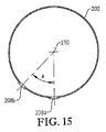
図15は、図13のライン15−15に沿った酸化剤スパージャーの側断面図であり、下方の酸化剤用開口部の幾何学的配置を特に示し;
図16は、反応器の底部出口近くに内部脱気容器を装着した気泡塔型反応器の側面図であり;
図17は、図18のライン17−17に沿った図16の気泡塔型反応器の下部(lower portion)の拡大側断面図であり、気泡塔型反応器の底部出口に配置された内部脱気容器の形状を特に示し;
図18は、図16のライン18−18に沿った上断面図であり、脱気容器中に配設されたボルテックスブレーカーを特に示し;
図19は、外部脱気容器を装着した気泡塔型反応器の側面図であり、脱気容器の底部から出る脱気されたスラリーの一部が、反応器の底部に連結されたデ−インベントリー・ライン(de-inventorying line)を流し出すのに用いられる様子を示し;
図20は、反応器の側部の高い位置から回収される反応媒体の気相を離脱させるための内部/外部複合型脱気容器を装着した気泡塔型反応器の側面図であり;
図21は、反応器の底部近くに代替複合型脱気容器を装着した気泡塔型反応器の側面図であり;
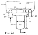
図22は、図21の気泡塔型反応器の下部の拡大側断面図であり、反応器の底部ヘッドを通して酸化剤流を受ける入口導管を用いる代替酸化剤スパージャーの使用を特に示し;
図23は、図22と同様な拡大側断面図であり、反応器中において酸化剤流をより均一に分配するための衝突板を場合によっては用いて、反応器の下部ヘッド中の多数の開口部を経て反応器中に酸化剤流を導入するための代替手段を特に示し;
図24は、反応器の上部(upper portion)から反応器の下部に反応媒体の一部を循環させることによって被酸化性化合物の分散の改善に役立つ内部流通導管を用いる気泡塔型反応器の側面図であり;
図25は、反応器の上部から反応器の下部に反応媒体の一部を循環させることによって被酸化性化合物の分散の改善に役立つ外部流通導管を用いる気泡塔型反応器の側面図であり;
図26は、酸化反応器内における被酸化性化合物の分散を改良するために使用できる横型エダクターの側断面図であり、反応媒体をエダクター中に引き込むために流入液体供給材料を用い且つ供給材料と反応媒体との混合物を高速で反応ゾーン中に排出するエダクターを特に示し;
図27は、酸化反応器中における被酸化性化合物の分散を改良するために使用できる縦型エダクターの側断面図であり、液体供給材料と流入ガスを合し、そして合した二相流体を用いて、反応媒体をエダクター中に引き込み且つ液体供給材料、流入気体及び反応媒体の混合物を高速で反応ゾーン中に排出するエダクターを特に示し;
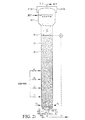
図28は、多相反応媒体を含む気泡塔型反応器の側面図であり、反応媒体中のいくつかの勾配を定量化するために等容積の30個の水平スライスに理論的に分割されている反応媒体を特に示し;
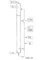
図29は、多相反応媒体を含む気泡塔型反応器の側面図であり、かなり異なる酸素濃度及び/又は酸素消費速度を有する、第1及び第2の独立した20%連続容量の反応媒体を特に示し;
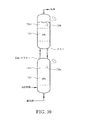
図30は、任意の機械的撹拌を用いる又は用いない、多相反応媒体を含む2つの積み重ね反応器の側面図であり、反応器が、かなり異なる酸素濃度及び/又は酸素消費速度を有する、独立した20%連続容量の反応媒体を含むことを特に示し;
図31は、任意の機械的撹拌を用いる又は用いない、多相反応媒体を含む3つの並列反応器の側面図であり、反応器が、かなり異なる酸素濃度及び/又は酸素消費速度を有する、独立した20%連続容量の反応媒体を含むことを特に示し;
図32A及び32Bは、本発明の一実施態様に従って製造された粗製テレフタル酸(CTA)粒子の拡大図であり、各CTA粒子が、多数の緩く結合したCTA子粒子から成る低密度高表面積の粒子であることを特に示し;
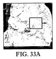
図33A及び33Bは、常法に従って製造されたCTAの拡大図であり、従来のCTA粒子は、図32A及び32Bの本発明のCTA粒子よりも粒度が大きく、密度が低く且つ表面積が小さいことを特に示し;
図34は、先行技術の精製テレフタル酸(PTA)の製造方法の簡略化した工程系統図であり;そして
図35は、本発明の一実施態様に係るPTA製造方法の簡略化した工程系統図である。
Preferred embodiments of the invention are described in detail below with reference to the figures of the accompanying drawings. In the attached drawings,
FIG. 1 is a side view of an oxidation reactor constructed in accordance with one embodiment of the present invention, introducing a feed stream, an oxidant stream and reflux into the reactor, the presence of a multiphase reaction medium in the reactor, and Specifically showing the recovery of gas and slurry from each of the top and bottom of the reactor;
FIG. 2 is an enlarged side cross-sectional view of the bottom of the bubble column reactor along line 2-2 of FIG. 3, showing the location and structure of the oxidant sparger used to introduce the oxidant stream into the reactor. In particular;
FIG. 3 is a top view of the oxidant sparger of FIG. 2, specifically showing the oxidant opening at the top of the oxidant sparger;
FIG. 4 is a bottom view of the oxidant sparger of FIG. 2, specifically showing an opening at the bottom of the oxidant sparger;
FIG. 5 is a cross-sectional side view of the oxidant sparger taken along line 5-5 of FIG. 3, specifically showing the top and bottom oxidant opening geometry of the oxidant sparger;
FIG. 6 is an enlarged side view of the bottom of a bubble column reactor, specifically showing a system for introducing a feed stream into the reactor at a plurality of vertically spaced locations;
FIG. 7 is a top cross-sectional view taken along line 7-7 of FIG. 6 in which the feedstock introduction system shown in FIG. 6 has a preferred radial feed zone (FZ) and more than one quadrant of azimuth (Q 1 , Q 2 , Q 3 , Q 4 ) in particular showing the distribution of the feed stream;
FIG. 8 is a top cross-sectional view similar to FIG. 7 but showing an alternative means for discharging the feed stream into the reactor using bayonet tubes each having a number of small feed openings;
FIG. 9 is an isometric view of an alternative system for introducing a feed stream into the reaction zone at a plurality of vertically spaced locations without the need for multiple vessel penetrations. Showing that it can be at least partially supported on an oxidant sparger;
FIG. 10 is a side view of the feed-through distribution system and oxidant sparger shown in FIG. 9;
FIG. 11 is a top cross-sectional view along line 11-11 of FIG. 10, with the penetrations supported on the oxidant sparger further showing one feed distribution system;
FIG. 12 is an isometric view of an alternative oxidant sparger with all of the oxidant openings located at the bottom of the ring member;
13 is a top view of the alternative oxidant sparger of FIG. 12;
14 is a bottom view of the alternative oxidant sparger of FIG. 12, specifically showing the location of the bottom opening for introducing the oxidant stream into the reaction zone;
FIG. 15 is a cross-sectional side view of the oxidant sparger along line 15-15 of FIG. 13, specifically showing the geometry of the lower oxidant opening;
FIG. 16 is a side view of a bubble column reactor equipped with an internal degassing vessel near the bottom outlet of the reactor;
FIG. 17 is an enlarged side cross-sectional view of the lower portion of the bubble column reactor of FIG. 16 taken along line 17-17 of FIG. 18, showing the internal escape located at the bottom outlet of the bubble column reactor. Specifically showing the shape of the air container;
18 is a top cross-sectional view taken along line 18-18 of FIG. 16, specifically showing a vortex breaker disposed in the deaeration vessel;
FIG. 19 is a side view of a bubble column reactor equipped with an external degassing vessel, in which a part of the degassed slurry exiting from the bottom of the degassing vessel is connected to the bottom of the reactor. -Shows how it is used to flush the de-inventorying line;
FIG. 20 is a side view of a bubble column reactor equipped with a combined internal / external degassing vessel for releasing the gas phase of the reaction medium recovered from a high position on the side of the reactor;
FIG. 21 is a side view of a bubble column reactor fitted with an alternative combined degassing vessel near the bottom of the reactor;
22 is an enlarged side cross-sectional view of the lower portion of the bubble column reactor of FIG. 21, specifically illustrating the use of an alternative oxidant sparger with an inlet conduit that receives an oxidant stream through the bottom head of the reactor;
FIG. 23 is an enlarged side cross-sectional view similar to FIG. 22, in which multiple apertures in the lower head of the reactor are optionally used, with impact plates for more evenly distributing the oxidant stream in the reactor. In particular an alternative means for introducing an oxidant stream into the reactor via the part;
FIG. 24 is a side view of a bubble column reactor using an internal flow conduit that helps improve the dispersion of oxidizable compounds by circulating a portion of the reaction medium from the upper portion of the reactor to the lower portion of the reactor. Is a figure;
FIG. 25 is a side view of a bubble column reactor using an external flow conduit that helps to improve the dispersion of oxidizable compounds by circulating a portion of the reaction medium from the top of the reactor to the bottom of the reactor;
FIG. 26 is a side cross-sectional view of a horizontal eductor that can be used to improve the dispersion of oxidizable compounds within an oxidation reactor, using an influent liquid feed to draw the reaction medium into the eductor and the feed. In particular shows an eductor discharging the mixture with the reaction medium at high speed into the reaction zone;
FIG. 27 is a cross-sectional side view of a vertical eductor that can be used to improve the dispersion of oxidizable compounds in an oxidation reactor, combining a liquid feed and an incoming gas and using a combined two-phase fluid. Particularly showing an eductor that draws the reaction medium into the eductor and discharges the liquid feed, incoming gas and reaction medium mixture into the reaction zone at high speed;
FIG. 28 is a side view of a bubble column reactor containing a multiphase reaction medium, theoretically divided into 30 horizontal slices of equal volume to quantify several gradients in the reaction medium. Specifically showing the reaction medium present;
FIG. 29 is a side view of a bubble column reactor containing a multiphase reaction medium, comprising first and second independent 20% continuous volume reaction media having significantly different oxygen concentrations and / or oxygen consumption rates. In particular;
FIG. 30 is a side view of two stacked reactors comprising a multiphase reaction medium with or without any mechanical agitation, where the reactors have significantly different oxygen concentrations and / or oxygen consumption rates. Specifically including a 20% continuous volume of reaction medium;
FIG. 31 is a side view of three parallel reactors comprising a multiphase reaction medium with or without any mechanical agitation, where the reactors have significantly different oxygen concentrations and / or oxygen consumption rates. Specifically including a 20% continuous volume of reaction medium;
32A and 32B are enlarged views of crude terephthalic acid (CTA) particles produced according to one embodiment of the present invention, each CTA particle having a low density, high surface area composed of a number of loosely bound CTA child particles. Specifically indicate that
FIGS. 33A and 33B are enlarged views of a CTA produced according to a conventional method, and the conventional CTA particles have a larger particle size, lower density and lower surface area than the CTA particles of the present invention of FIGS. 32A and 32B. In particular;
FIG. 34 is a simplified process flow diagram of a prior art method for producing purified terephthalic acid (PTA); and FIG. 35 is a simplified process flow diagram of a PTA production method according to one embodiment of the present invention. is there.
本発明の一実施態様は被酸化性化合物の液相部分酸化に関する。このような酸化は、好ましくは1つ又はそれ以上の撹拌反応器中に含まれる多相反応媒体の液相中で行う。適当な撹拌反応器としては、例えば気泡撹拌反応器(例えば気泡塔型反応器)、機械的撹拌反応器(例えば連続撹拌漕型反応器)及び流動撹拌反応器(例えばジェット反応器)が挙げられる。本発明の一実施態様において液相酸化は単一の気泡塔型反応器中で実施する。 One embodiment of the invention relates to liquid phase partial oxidation of oxidizable compounds. Such oxidation is preferably carried out in the liquid phase of the multiphase reaction medium contained in one or more stirred reactors. Suitable agitation reactors include, for example, bubble agitation reactors (eg bubble column reactors), mechanical agitation reactors (eg continuous agitation reactors) and fluidized agitation reactors (eg jet reactors). . In one embodiment of the invention, liquid phase oxidation is carried out in a single bubble column reactor.
本明細書中で使用する用語「気泡塔型反応器」は、反応撹拌が、主に反応媒体を通る気泡の上向きの移動によって提供される、多相反応媒体中で化学反応を促進するための反応器を意味するものとする。本明細書中で使用する用語「撹拌」は、流体の流れ及び/又は混合を引き起こす反応媒体中に放散される仕事を意味するものとする。本明細書中で使用する用語「大部分」、「主に」及び「主として」は、50%超を意味するものとする。本明細書中で使用する用語「機械的撹拌」は、反応媒体に逆らう又は反応媒体内部における1つ又は複数の硬質又は軟質要素の物理的移動によって引き起こされる反応媒体の撹拌を意味するものとする。例えば、機械的撹拌は、反応媒体中に配置された内部撹拌機、パドル、バイブレーター又は音響振動板の回転、往復運動(oscillation)及び/又は振動(vibration)によって提供されることができる。本明細書中で使用する用語「流動撹拌」は、反応媒体中の1種又はそれ以上の流体の高速噴射及び/又は再循環によって引き起こされる反応媒体の撹拌を意味するものとする。例えば、流動撹拌は、ノズル、エジェクター及び/又はエダクターによって提供されることができる。 As used herein, the term “bubble column reactor” is used to promote a chemical reaction in a multiphase reaction medium where reaction agitation is provided primarily by upward movement of bubbles through the reaction medium. It shall mean a reactor. The term “stirring” as used herein shall mean work dissipated into the reaction medium that causes fluid flow and / or mixing. As used herein, the terms “major”, “mainly” and “mainly” shall mean greater than 50%. The term “mechanical agitation” as used herein shall mean agitation of the reaction medium caused by physical movement of one or more hard or soft elements against the reaction medium or within the reaction medium. . For example, mechanical agitation can be provided by rotation, reciprocation and / or vibration of an internal agitator, paddle, vibrator or acoustic diaphragm placed in the reaction medium. As used herein, the term “fluid agitation” shall mean agitation of the reaction medium caused by high-speed jetting and / or recirculation of one or more fluids in the reaction medium. For example, fluid agitation can be provided by a nozzle, ejector and / or eductor.
本発明の好ましい実施態様においては、酸化の間における気泡塔型反応器中の反応媒体の撹拌の約40%未満、より好ましくは約20%未満、最も好ましくは5%未満が、機械的及び/又は流動撹拌によって提供される。好ましくは、酸化の間に多相反応媒体に与えられる機械的及び/又は機械的撹拌の量は、反応媒体立方メートル当たり約3キロワット未満、より好ましくは反応媒体立方メートル当たり約2キロワット未満、最も好ましくは反応媒体立方メートル当たり1キロワット未満である。 In a preferred embodiment of the invention, less than about 40%, more preferably less than about 20%, most preferably less than 5% of the stirring of the reaction medium in the bubble column reactor during oxidation is mechanical and / or Or provided by fluid agitation. Preferably, the amount of mechanical and / or mechanical agitation imparted to the multiphase reaction medium during oxidation is less than about 3 kilowatts per cubic meter of reaction medium, more preferably less than about 2 kilowatts per cubic meter of reaction medium, most preferably Less than 1 kilowatt per cubic meter of reaction medium.
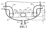
図1を参照すると、好ましい気泡塔型反応器20が、反応セクション24及び離脱セクション(disengagement section)26を有する容器シェル22を含むものとして示されている。反応セクション24は内部反応ゾーン28を規定し、離脱セクション26は内部離脱ゾーン30を規定する。主として液相の供給流は、供給口32a、b、c及びdを経て反応ゾーン28に導入される。主として気相の酸化剤流は、反応ゾーン28の下部部分に配置された酸化剤スパージャー34を経て反応ゾーン28に導入される。液相供給材料流及び気相酸化剤流は共同で反応ゾーン28内に多相反応媒体36を形成する。多相反応媒体36は、液相と気相を含む。より好ましくは多相反応媒体36は、固相、液相及び気相成分を有する三相媒体を含む。反応媒体36の固相成分は好ましくは、反応媒体36の液相中で行われる酸化反応の結果として反応ゾーン28内に沈殿する。気泡塔型反応器20は、反応ゾーン28の底部近くに配置されたスラリー出口38及び離脱ゾーン30の頂部近くに配置された気体出口40を含む。反応媒体36の液相成分及び固相成分を含むスラリー流出物は、スラリー出口38を経て反応ゾーン28から回収され、主として気体の流出物は気体出口40を経て離脱ゾーン30から回収される。
Referring to FIG. 1, a preferred
供給口32a、b、c及びdを経て気泡塔型反応器20中に導入される液相供給流は好ましくは、被酸化性化合物、溶媒及び触媒系を含む。
The liquid phase feed stream introduced into
液相供給流中に存在する被酸化性化合物は好ましくは、少なくとも1個のヒドロカルビル基を含む。より好ましくは、被酸化性化合物は芳香族化合物である。更に好ましくは、被酸化性化合物は、少なくとも1個の結合したヒドロカルビル基又は少なくとも1個の結合した置換ヒドロカルビル基又は少なくとも1個の結合したヘテロ原子又は少なくとも1個の結合したカルボン酸基(−COOH)を有する芳香族化合物である。更に好ましくは、被酸化性化合物は、少なくとも1個の結合したヒドロカルビル基又は少なくとも1個の結合した置換ヒドロカルビル基を有し且つ各結合基が1〜5個の炭素原子を有する芳香族化合物である。更に好ましくは、被酸化性化合物は、ちょうど2個の結合基を有する芳香族化合物であって、各結合基は、ちょうど1個の炭素原子を含み且つメチル基及び/又は置換メチル基及び/又は最大限でも1個のカルボン酸基を含む。更に好ましくは、被酸化性化合物は、p−キシレン、m−キシレン、p−トルアルデヒド、m−トルアルデヒド、p−トルイル酸、m−トルイル酸及び/又はアセトアルデヒドである。最も好ましくは、被酸化性化合物はp−キシレンである。 The oxidizable compound present in the liquid phase feed stream preferably comprises at least one hydrocarbyl group. More preferably, the oxidizable compound is an aromatic compound. More preferably, the oxidizable compound comprises at least one bonded hydrocarbyl group or at least one bonded substituted hydrocarbyl group or at least one bonded heteroatom or at least one bonded carboxylic acid group (—COOH ). More preferably, the oxidizable compound is an aromatic compound having at least one bonded hydrocarbyl group or at least one bonded substituted hydrocarbyl group, each linking group having 1 to 5 carbon atoms. . More preferably, the oxidizable compound is an aromatic compound having exactly two linking groups, each linking group comprising exactly one carbon atom and a methyl group and / or a substituted methyl group and / or Contains at most one carboxylic acid group. More preferably, the oxidizable compound is p-xylene, m-xylene, p-tolualdehyde, m-tolualdehyde, p-toluic acid, m-toluic acid and / or acetaldehyde. Most preferably, the oxidizable compound is p-xylene.
ここで定義する「ヒドロカルビル基」は、水素原子又は他の炭素原子にのみ結合した少なくとも1個の炭素原子である。ここで定義する「置換ヒドロカルビル基」は、少なくとも1個のヘテロ原子及び少なくとも1個の水素原子に結合した少なくとも1個の炭素原子である。ここで定義する「ヘテロ原子」は、炭素及び水素原子以外の全ての原子である。ここで定義する芳香族化合物は芳香環、好ましくは環の一部として少なくとも6個の炭素原子を有する、より好ましくは炭素原子のみを有する芳香環を含む。このような芳香環の適当な例としては、例えばベンゼン、ビフェニル、テルフェニル、ナフタレン及び他の炭素系縮合芳香環が挙げられるが、これらに限定するものではない。 A “hydrocarbyl group” as defined herein is at least one carbon atom bonded only to a hydrogen atom or other carbon atom. A “substituted hydrocarbyl group” as defined herein is at least one carbon atom bonded to at least one heteroatom and at least one hydrogen atom. A “heteroatom” as defined herein is any atom other than carbon and hydrogen atoms. Aromatic compounds as defined herein include aromatic rings, preferably aromatic rings having at least 6 carbon atoms as part of the ring, more preferably having only carbon atoms. Suitable examples of such aromatic rings include, but are not limited to, benzene, biphenyl, terphenyl, naphthalene and other carbon-based condensed aromatic rings.
被酸化性化合物の適当な例は以下のものを含む。脂肪族炭化水素(例えばアルカン、分岐鎖アルカン、環状アルカン、脂肪族アルケン、分岐鎖アルケン及び環状アルケン);脂肪族アルデヒド(例えばアセトアルデヒド、プロピオンアルデヒド、イソブチルアルデヒド及びn−ブチルアルデヒド);脂肪族アルコール(例えばエタノール、イソプロパノール、n−プロパノール、n−ブタノール、及びイソブタノール);脂肪族ケトン(例えばジメチルケトン、エチルメチルケトン、ジエチルケトン及びイソプロピルメチルケトン);脂肪族エステル(例えば蟻酸メチル、酢酸メチル、酢酸エチル);脂肪族過酸化物、過酸及びヒドロペルオキシド(例えばt−ブチルヒドロペルオキシド、過酢酸及びジ−t−ブチルヒドロペルオキシド);前記脂肪族種と他のヘテロ原子との組合せである基を有する脂肪族化合物(例えば炭化水素、アルデヒド、アルコール、ケトン、エステル、ペルオキシド、過酸及び/又はヒドロペルオキシドの1個又はそれ以上の分子セグメントを、ナトリウム、臭素、コバルト、マンガン及びジルコニウムと共に含む脂肪族化合物);1個又はそれ以上の結合したヒドロカルビル基を有する種々のベンゼン環、ナフタレン環、ビフェニル、テルフェニル及び他の芳香族基(例えばトルエン、エチルベンゼン、イソプロピルベンゼン、n−プロピルベンゼン、ネオペンチルベンゼン、p−キシレン、m−キシレン、o−キシレン、トリメチルベンゼンの全ての異性体、テトラメチルベンゼンの全ての異性体、ペンタメチルベンゼン、ヘキサメチルベンゼン、エチル−メチルベンゼンの全ての異性体、ジエチルベンゼンの全ての異性体、エチル−ジメチルベンゼンの全ての異性体、ジメチルナフタレンの全ての異性体、エチル−メチルナフタレンの全ての異性体、ジエチルナフタレンの全ての異性体、ジメチルビフェニルの全ての異性体、エチル−メチルビフェニルの全ての異性体、並びにスチルベン及び1個又はそれ以上の結合ヒドロカルビル基を有するスチルベン、フルオレン及び1個又はそれ以上の結合ヒドロカルビル基を有するフルオレン、アントラセン及び1個又はそれ以上の結合ヒドロカルビル基を有するアントラセン並びにジフェニルエタン及び1個又はそれ以上の結合ヒドロカルビル基を有するジフェニルエタン);他の原子又は原子の基に接続できる、1個若しくはそれ以上の結合ヒドロカルビル基及び/又は1個若しくはそれ以上の結合ヘテロ原子を有する種々のベンゼン環、ナフタレン環、ビフェニル、テルフェニル及び他の芳香族基(例えばフェノール、メチルフェノールの全ての異性体、ジメチルフェノールの全ての異性体、ナフトールの全ての異性体、ベンジルメチルエーテル、ブロモフェノールの全ての異性体、ブロモベンゼン、α―ブロモトルエンを含むブロモトルエンの全ての異性体、ジブロモベンゼン、コバルトナフタレン及びブロモビフェニルの全ての異性体);1個若しくはそれ以上の結合したヒドロカルビル基及び/又は1個若しくはそれ以上の結合したヘテロ原子及び/又は1個若しくはそれ以上の結合した置換ヒドロカルビル基を有する種々のベンゼン環、ナフタレン環、ビフェニル、テルフェニル及び他の芳香族基(例えばベンズアルデヒド、ブロモベンズアルデヒドの全ての異性体、α−ブロモトルアルデヒドの全ての異性体を含む臭素化トルアルデヒドの全ての異性体、ヒドロキシベンズアルデヒドの全ての異性体、ブロモ−ヒドロキシベンズアルデヒドの全ての異性体、ベンゼンジカルボキシアルデヒドの全ての異性体、ベンゼントリカルボキシアルデヒドの全ての異性体、p−トルアルデヒド、m−トルアルデヒド、o−トルアルデヒド、トルエンジカルボキシアルデヒドの全ての異性体、トルエントリカルボキシアルデヒドの全ての異性体、トルエンテトラカルボキシアルデヒドの全ての異性体、ジメチルベンゼンジカルボキシアルデヒドの全ての異性体、ジメチルベンゼントリカルボキシアルデヒドの全ての異性体、ジメチルベンゼンテトラカルボキシアルデヒドの全ての異性体、トリメチルベンゼントリカルボキシアルデヒドの全ての異性体、エチルトルアルデヒドの全ての異性体、トリメチルベンゼンジカルボキシアルデヒドの全ての異性体、テトラメチルベンゼンジカルボキシアルデヒド、ヒドロキシメチル−ベンゼン、ヒドロキソメチル−トルエンの全ての異性体、ヒドロキシメチル−ブロモトルエンの全ての異性体、ヒドロキシメチル−トルアルデヒドの全ての異性体、ヒドロキシメチル−ブロモトルアルデヒドの全ての異性体、ベンジルヒドロペルオキシド、ベンゾイルヒドロペルオキシド、トリルメチル−ヒドロペルオキシドの全ての異性体及びメチルフェノールメチル−ヒドロペルオキシドの全ての異性体);1個若しくはそれ以上の結合された選択基(選択基とは、ヒドロカルビル基及び/又は結合されたヘテロ原子及び/又は置換ヒドロカルビル基及び/又はカルボン酸基及び/又はペルオキシ酸基を意味する)を有する種々のベンゼン環、ナフタレン環、ビフェニル、テルフェニル及び他の芳香族基(例えば安息香酸、p−トルイル酸、m−トルイル酸、o−トルイル酸、エチル安息香酸の全ての異性体、プロピル安息香酸の全ての異性体、ブチル安息香酸の全ての異性体、ペンチル安息香酸の全ての異性体、ジメチル安息香酸の全ての異性体、エチルメチル安息香酸の全ての異性体、トリメチル安息香酸の全ての異性体、テトラメチル安息香酸の全ての異性体、ペンタメチル安息香酸、ジエチル安息香酸の全ての異性体、ベンゼンジカルボン酸の全ての異性体、ベンゼントリカルボン酸の全ての異性体、メチルベンゼンジカルボン酸の全ての異性体、ジメチルベンゼンジカルボン酸の全ての異性体、メチルベンゼントリカルボン酸の全ての異性体、ブロモ安息香酸の全ての異性体、ジブロモ安息香酸の全ての異性体、α−ブロモトルイル酸を含むブロモトルイル酸の全ての異性体、トリル酢酸、ヒドロキシ安息香酸の全ての異性体、ヒドロキシメチル−安息香酸の全ての異性体、ヒドロキシトルイル酸の全ての異性体、ヒドロキシメチル−トルイル酸の全ての異性体、ヒドロキシメチル−ベンゼンジカルボン酸の全ての異性体、ヒドロキシブロモ安息香酸の全ての異性体、ヒドロキシブロモトルイル酸の全ての異性体、ヒドロキシメチル−ブロモ安息香酸の全ての異性体、カルボキシベンズアルデヒドの全ての異性体、ジカルボキシベンズアルデヒドの全ての異性体、過安息香酸、ヒドロペルオキシメチル−安息香酸の全ての異性体、ヒドロペルオキシメチル−ヒドロキシ安息香酸の全ての異性体、ヒドロペルオキシカルボニル−安息香酸の全ての異性体、ヒドロペルオキシカルボニル−トルエンの全ての異性体、メチルビフェニルカルボン酸の全ての異性体、ジメチルビフェニルカルボン酸の全ての異性体、メチルビフェニルジカルボン酸の全ての異性体、ビフェニルトリカルボン酸の全ての異性体、1個若しくはそれ以上の結合した選択基を有するスチルベンの全ての異性体、1個若しくはそれ以上の結合した選択基を有するフルオレノンの全ての異性体、1個若しくはそれ以上の結合した選択基を有するナフタレンの全ての異性体、ベンジル、1個若しくはそれ以上の結合した選択基を有するベンジルの全ての異性体、ベンゾフェノン、1個若しくはそれ以上の結合した選択基を有するベンゾフェノンの全ての異性体、アントラキノン、1個若しくはそれ以上の結合した選択基を有するアントラキノンの全ての異性体、1個若しくはそれ以上の結合した選択基を有するジフェニルエタンの全ての異性体、ベンゾクマリン及び1個若しくはそれ以上の結合した選択基を有するベンゾクマリンの全ての異性体)。 Suitable examples of oxidizable compounds include: Aliphatic hydrocarbons (eg alkanes, branched alkanes, cyclic alkanes, aliphatic alkenes, branched alkenes and cyclic alkenes); aliphatic aldehydes (eg acetaldehyde, propionaldehyde, isobutyraldehyde and n-butyraldehyde); aliphatic alcohols ( Eg ethanol, isopropanol, n-propanol, n-butanol, and isobutanol); aliphatic ketones (eg dimethyl ketone, ethyl methyl ketone, diethyl ketone and isopropyl methyl ketone); aliphatic esters (eg methyl formate, methyl acetate, acetic acid) Ethyl); aliphatic peroxides, peracids and hydroperoxides (eg t-butyl hydroperoxide, peracetic acid and di-t-butyl hydroperoxide); combinations of said aliphatic species with other heteroatoms Fatty compounds having one or more molecular segments of hydrocarbons, aldehydes, alcohols, ketones, esters, peroxides, peracids and / or hydroperoxides together with sodium, bromine, cobalt, manganese and zirconium Various benzene rings, naphthalene rings, biphenyl, terphenyl and other aromatic groups (eg toluene, ethylbenzene, isopropylbenzene, n-propylbenzene, neopentyl) having one or more attached hydrocarbyl groups Benzene, p-xylene, m-xylene, o-xylene, all isomers of trimethylbenzene, all isomers of tetramethylbenzene, all isomers of pentamethylbenzene, hexamethylbenzene, ethyl-methylbenzene, diethyl All isomers of benzene, all isomers of ethyl-dimethylbenzene, all isomers of dimethylnaphthalene, all isomers of ethyl-methylnaphthalene, all isomers of diethylnaphthalene, all isomers of dimethylbiphenyl , All isomers of ethyl-methylbiphenyl, and stilbene with stilbene and one or more linked hydrocarbyl groups, fluorene and fluorene with one or more linked hydrocarbyl groups, anthracene and one or more Anthracene with bound hydrocarbyl groups and diphenylethane and diphenylethane with one or more bound hydrocarbyl groups); one or more bound hydrocarbyl groups and / or one that can be connected to other atoms or groups of atoms Or more Various benzene rings, naphthalene rings, biphenyls, terphenyls and other aromatic groups with bonded heteroatoms above (eg phenol, all isomers of methylphenol, all isomers of dimethylphenol, all isomers of naphthol) , Benzyl methyl ether, all isomers of bromophenol, bromobenzene, all isomers of bromotoluene including α-bromotoluene, all isomers of dibromobenzene, cobalt naphthalene and bromobiphenyl); one or more Various benzene rings, naphthalene rings, biphenyls, terphenyls and others having the above bonded hydrocarbyl groups and / or one or more bonded heteroatoms and / or one or more bonded substituted hydrocarbyl groups Aromatic groups (eg benzalde , All isomers of bromobenzaldehyde, all isomers of brominated tolualdehyde including all isomers of α-bromotolualdehyde, all isomers of hydroxybenzaldehyde, all isomers of bromo-hydroxybenzaldehyde, All isomers of benzenedicarboxaldehyde, all isomers of benzenetricarboxaldehyde, p-tolualdehyde, m-tolualdehyde, o-tolualdehyde, all isomers of toluene dicarboxaldehyde, All isomers, all isomers of toluenetetracarboxaldehyde, all isomers of dimethylbenzenedicarboxaldehyde, all isomers of dimethylbenzenetricarboxaldehyde, of dimethylbenzenetetracarboxaldehyde All isomers, all isomers of trimethylbenzene tricarboxaldehyde, all isomers of ethyl tolualdehyde, all isomers of trimethylbenzene dicarboxaldehyde, tetramethylbenzene dicarboxaldehyde, hydroxymethyl-benzene, hydroxomethyl All isomers of toluene, all isomers of hydroxymethyl-bromotoluene, all isomers of hydroxymethyl-tolualdehyde, all isomers of hydroxymethyl-bromotolualdehyde, benzyl hydroperoxide, benzoyl hydroperoxide, All isomers of tolylmethyl-hydroperoxide and all isomers of methylphenolmethyl-hydroperoxide); one or more linked select groups (selective groups are hydrocarbyl groups and Various benzene rings, naphthalene rings, biphenyls, terphenyls and other aromatic groups (meaning bonded heteroatoms and / or substituted hydrocarbyl groups and / or carboxylic acid groups and / or peroxy acid groups) For example, benzoic acid, p-toluic acid, m-toluic acid, o-toluic acid, all isomers of ethylbenzoic acid, all isomers of propylbenzoic acid, all isomers of butylbenzoic acid, pentylbenzoic acid All isomers, all isomers of dimethylbenzoic acid, all isomers of ethylmethylbenzoic acid, all isomers of trimethylbenzoic acid, all isomers of tetramethylbenzoic acid, pentamethylbenzoic acid, diethylbenzoic acid All isomers, all isomers of benzenedicarboxylic acid, all isomers of benzenetricarboxylic acid, methylbenzenedi All isomers of carboxylic acids, all isomers of dimethylbenzenedicarboxylic acid, all isomers of methylbenzenetricarboxylic acid, all isomers of bromobenzoic acid, all isomers of dibromobenzoic acid, α-bromotoluic acid All isomers of bromotoluic acid, including tolylacetic acid, all isomers of hydroxybenzoic acid, all isomers of hydroxymethyl-benzoic acid, all isomers of hydroxytoluic acid, all of hydroxymethyl-toluic acid Isomers, all isomers of hydroxymethyl-benzenedicarboxylic acid, all isomers of hydroxybromobenzoic acid, all isomers of hydroxybromotoluic acid, all isomers of hydroxymethyl-bromobenzoic acid, of carboxybenzaldehyde All isomers, all dicarboxybenzaldehydes Body, perbenzoic acid, all isomers of hydroperoxymethyl-benzoic acid, all isomers of hydroperoxymethyl-hydroxybenzoic acid, all isomers of hydroperoxycarbonyl-benzoic acid, all of hydroperoxycarbonyl-toluene Isomers, all isomers of methylbiphenyl carboxylic acid, all isomers of dimethyl biphenyl carboxylic acid, all isomers of methyl biphenyl dicarboxylic acid, all isomers of biphenyl tricarboxylic acid, one or more bonds All isomers of stilbene with selected groups, all isomers of fluorenone with one or more attached select groups, all isomers of naphthalene with one or more attached select groups, Benzyl, one having one or more attached selective groups All isomers of Gil, benzophenone, all isomers of benzophenone with one or more attached select groups, anthraquinone, all isomers of anthraquinone with one or more attached select groups, 1 All isomers of diphenylethane with one or more linked select groups, benzocoumarin and all isomers of benzocoumarin with one or more linked select groups).
液相供給流中に存在する被酸化性化合物が、常態では固体の(即ち標準温度及び圧力で固体の)化合物である場合には、被酸化性化合物は、反応ゾーン28に導入されると、溶媒中に実質的に溶解されるのが好ましい。大気圧における被酸化性化合物の沸点は少なくとも約50℃であるのが好ましい。より好ましくは、被酸化性化合物の沸点は、約80〜約400℃、最も好ましくは125〜155℃の範囲である。液相供給材料中に存在する被酸化性化合物の量は、好ましくは約2〜約40重量%、より好ましくは約4〜約20重量%、最も好ましくは6〜15重量%の範囲である。
If the oxidizable compound present in the liquid phase feed stream is normally a solid (ie solid at standard temperature and pressure), the oxidizable compound is introduced into the
液相供給材料中に存在する被酸化性化合物は2種又はそれ以上の異なる被酸化性化学物質の組合せを含むことが注目される。これらの2種又はそれ以上の異なる化学物質は、液相供給流中に混ぜ合わせて供給することもできるし、或いは複数の供給流で別々の供給することもできる。例えば、p−キシレン、m−キシレン、p−トルアルデヒド、p−トルイル酸及びアセトアルデヒドを含む被酸化性化合物は、単一の入口又は複数の別々の入口を経て反応器に供給することができる。 It is noted that the oxidizable compounds present in the liquid phase feed include a combination of two or more different oxidizable chemicals. These two or more different chemicals can be fed in a liquid phase feed stream or can be fed separately in multiple feed streams. For example, oxidizable compounds including p-xylene, m-xylene, p-tolualdehyde, p-toluic acid, and acetaldehyde can be fed to the reactor via a single inlet or multiple separate inlets.
液相供給流中に存在する溶媒は、好ましくは酸成分及び水成分を含む。溶媒は、好ましくは液相供給流中に約60〜約98重量%、より好ましくは約80〜約96重量%、最も好ましくは85〜94重量%の範囲の濃度で存在する。溶媒の酸成分は、好ましくは主に、炭素数1〜6の、より好ましくは炭素数2の有機低分子量モノカルボン酸である。最も好ましくは、溶媒の酸成分は主に酢酸である。好ましくは、酸成分は溶媒の少なくとも約75重量%、より好ましくは溶媒の少なくとも約80重量%、最も好ましくは溶媒の85〜98重量%を構成し、残りは主に水である。気泡塔型反応器20に導入される溶媒は、少量の不純物、例えばp−トルアルデヒド、テレフタルアルデヒド、4−カルボキシベンズアルデヒド(4−CBA)、安息香酸、p−トルイル酸、p−トルイル酸アルデヒド、α−ブロモ−p−トルイル酸、イソフタル酸、フタル酸、トリメリット酸、多環芳香族炭化水素及び/又は浮遊粒子を含むことができる。気泡塔型反応器20中に導入される溶媒中の不純物の総量は約3重量%未満であるのが好ましい。
The solvent present in the liquid phase feed stream preferably comprises an acid component and a water component. The solvent is preferably present in the liquid phase feed stream at a concentration ranging from about 60 to about 98 wt%, more preferably from about 80 to about 96 wt%, and most preferably from 85 to 94 wt%. The acid component of the solvent is preferably mainly an organic low molecular weight monocarboxylic acid having 1 to 6 carbon atoms, more preferably 2 carbon atoms. Most preferably, the acid component of the solvent is primarily acetic acid. Preferably, the acid component comprises at least about 75% by weight of the solvent, more preferably at least about 80% by weight of the solvent, most preferably 85-98% by weight of the solvent, with the remainder being predominantly water. Solvents introduced into the
液相供給流中に存在する触媒系は、好ましくは被酸化性化合物の酸化(部分酸化を含む)を促進できる均一液相触媒系である。より好ましくは、触媒系は、少なくとも1種の多価遷移金属を含む。更に好ましくは、多価遷移金属はコバルトを含む。更に好ましくは、触媒系はコバルト及び臭素を含む。最も好ましくは、触媒系はコバルト、臭素及びマンガンを含む。 The catalyst system present in the liquid phase feed stream is preferably a homogeneous liquid phase catalyst system that can promote the oxidation (including partial oxidation) of the oxidizable compound. More preferably, the catalyst system comprises at least one multivalent transition metal. More preferably, the multivalent transition metal comprises cobalt. More preferably, the catalyst system comprises cobalt and bromine. Most preferably, the catalyst system comprises cobalt, bromine and manganese.
コバルトが触媒系中に存在する場合には、液相供給流中に存在するコバルトの量は、反応媒体36の液相中のコバルト濃度が約300〜約6,000重量百万分率(ppmw)、より好ましくは約700〜約4,200ppmw、最も好ましくは1,200〜3,000ppmwの範囲に保持されるような量であるのが好ましい。臭素が触媒系中に存在する場合には、液相供給流中に存在する臭素の量は、反応媒体36の液相中の臭素濃度が約300〜約5,000ppmw、より好ましくは約600〜約4,000ppmw、最も好ましくは900〜3,000ppmwの範囲に保持されるような量であるのが好ましい。マンガンが触媒系中に存在する場合には、液相供給流中に存在するマンガンの量は、反応媒体36の液相中のマンガン濃度が約20〜約1,000ppmw、より好ましくは約40〜約500ppmw、最も好ましくは50〜200ppmwの範囲に保持されるような量であるのが好ましい。
When cobalt is present in the catalyst system, the amount of cobalt present in the liquid phase feed stream is such that the cobalt concentration in the liquid phase of the
前に示した、反応媒体36の液相中のコバルト、臭素及び/又はマンガンの濃度は、時間平均及び容量平均で表されている。ここで使用する用語「時間平均」は、少なくとも100秒の連続期間にわたって同様に取られた少なくとも10個の測定値の平均を意味するものとする。ここで使用する「容量平均」は、ある容量全体にわたって均一な三次元間隔で取られた少なくとも10個の平均を意味するものとする。
The previously shown concentrations of cobalt, bromine and / or manganese in the liquid phase of the
反応ゾーン28中に導入される触媒系中のコバルト対臭素の重量比(Co:Br)は好ましくは約0.25:1〜約4:1、より好ましくは約0.5:1〜約3:1、最も好ましくは0.75:1〜2:1の範囲である。反応ゾーン28中に導入される触媒系中のコバルト対マンガンの重量比(Co:Mn)は好ましくは約0.3:1〜約40:1、より好ましくは約5:1〜約30:1、最も好ましくは10:1〜25:1の範囲である。
The weight ratio of cobalt to bromine (Co: Br) in the catalyst system introduced into
気泡塔型反応器20に導入される液相供給流は少量の不純物、例えばトルエン、エチルベンゼン、p−トルアルデヒド、テレフタルアルデヒド、4−カルボキシベンズアルデヒド(4−CBA)、安息香酸、p−トルイル酸、p−トルアルデヒド、α−ブロモ−p−トルイル酸、イソフタル酸、フタル酸、トリメリット酸、多環芳香族炭化水素、及び/又は浮遊粒子を含むことができる。気泡塔型反応器20をテレフタル酸の製造に用いる場合には、m−キシレン及びo−キシレンも不純物と見なされる。気泡塔型反応器20中に導入される液相供給流中の不純物の総量は約3重量%未満であるのが好ましい。
The liquid phase feed stream introduced into the
図1は、被酸化性化合物、溶媒及び触媒系を一緒に混合して、単一供給流として気泡塔型反応器20に導入する一態様を示すが、本発明の別の実施態様においては、被酸化性化合物、溶媒及び触媒は気泡塔型反応器20中に別々に導入することができる。例えば純粋なp−キシレン流は溶媒及び触媒の入口とは別の入口を介して気泡塔型反応器20中に供給できる。
FIG. 1 shows one embodiment where the oxidizable compound, solvent and catalyst system are mixed together and introduced into the
酸化剤スパージャー34を経て気泡塔型反応器20中に導入される、主として気相の酸化剤流は、分子状酸素(O2)を含む。好ましくは、酸化剤流は約5〜約40モル%、より好ましくは約15〜約30モル%、最も好ましくは18〜24モル%の範囲の酸素分子を含む。酸化剤流の残りは、酸化に不活性な窒素のような1種又はそれ以上の気体から主になるのが好ましい。より好ましくは、酸化剤流は分子状酸素及び窒素から本質的になる。最も好ましくは、酸化剤流は、約21モル%の分子状酸素及び約78〜約81モル%の窒素を含む乾燥空気である。本発明の別の実施態様において、酸化剤流は、実質的に純粋な酸素を含むことができる。
The predominantly gaseous oxidant stream introduced into
再び図1を参照すると、気泡塔型反応器20には、好ましくは反応媒体36の上面44の上方に還流分配器42が装着される。還流分配器42は、公知の任意の液滴形成手段によって離脱ゾーン30中に主として液相の還流の液滴を導入する働きをする。より好ましくは、還流分配器42は、反応媒体36の上面44に向かって下方に向けられた液滴の噴霧を生じる。好ましくは、この下向きの液滴噴霧は、離脱ゾーン30の最大水平断面積の少なくとも約50%に作用する(即ち、関与して、影響を与える)。より好ましくは、液滴噴霧は離脱ゾーン30の最大水平断面積の少なくとも約75%に作用する。最も好ましくは、液滴噴霧は離脱ゾーン30の最大水平断面積の少なくとも90%に作用する。この下向きの液体還流噴霧は、反応媒体36の上面44又はその上方における泡立ちを防止するのに役立つことができ、更に、気体出口40に向かって流れる上方に移動する気体に同伴される任意の液体又はスラリー液滴の離脱を助けることができる。更に、液体還流は、気体出口40を経て離脱ゾーン30から回収される気体流出物中に存在する粒子状物質及び沈殿する可能性のある化合物(例えば溶解されている安息香酸、p−トルイル酸、4−CBA、テレフタル酸、触媒金属塩)の量を減少させる働きをすることができる。更に、離脱ゾーン30中への還流液滴の導入は、蒸留作用によって、気体出口40を経て回収される気体流出物の組成を調整するのに用いることができる。
Referring again to FIG. 1, the
還流分配器42を経て気泡塔型反応器20中に導入される液体還流は、好ましくは供給口32a、b、c及びdを経て気泡塔型反応器20中に導入される液相供給流の溶媒成分と概ね同じ組成を有する。従って、液体還流は酸成分及び水を含むのが好ましい。還流の酸成分は好ましくは炭素数1〜6、より好ましくは炭素数2の低分子量有機モノカルボン酸である。最も好ましくは、還流の酸成分は酢酸である。好ましくは、酸成分は還流の少なくとも約75重量%、より好ましくは少なくとも約80重量%、最も好ましくは85〜98重量%を構成し、残りは水である。還流は典型的には、液相供給流中の溶媒と実質的に同じ組成を有するので、この記載が反応器に導入される「総溶媒」に言及する場合には、このような「総溶媒」は、還流と供給流の溶媒部分の両方を含むものとする。
The liquid reflux introduced into the
気泡塔型反応器20中の液相酸化の間には、気体及びスラリー流出物流が反応器ゾーン28から実質的に連続的に回収されながら、供給材料、酸化剤及び還流が、反応ゾーン28に実質的に連続的に導入されるのが好ましい。ここで使用する用語「実質的に連続的に」は、10分未満しか中断されない少なくとも10時間の期間を意味する。酸化の間において、被酸化性化合物(例えば、p−キシレン)は少なくとも約8,000kg/時、より好ましくは約13,000〜約80,000kg/時の範囲、更に好ましくは約18,000〜約50,000kg/時の範囲、最も好ましくは22,000〜30,000kg/時の範囲の速度で反応ゾーン28に実質的に連続的に導入されるのが好ましい。入ってくる供給材料、酸化剤及び還流の流速は実質的に定常であるのが一般に好ましいが、本発明の一実施態様は、混合及び物質移動を改善するために、入ってくる供給材料、酸化剤及び/又は還流を脈動させることを考慮していることが注目される。入ってくる供給材料、酸化剤及び/又は還流がパルスで導入される場合には、それらの流速は、ここに挙げた定常状態の流速の約0〜約500%の範囲内で、より好ましくは約30〜約200%の範囲内で、最も好ましくは80〜120%の範囲内で変動するのが望ましい。
During liquid phase oxidation in
気泡塔型反応器20中における平均空時反応速度(average space-time rate of reaction:STR)を、供給される被酸化性化合物の質量/反応媒体36の単位容量/単位時間(例えばp−キシレンのkg/m3/時)と定義する。慣例的用法では、生成物に転化されない被酸化性化合物の量は、典型的にはSTRの計算前に供給流中の被酸化性化合物の量から差し引かれるであろう。しかし、ここで好ましい被酸化性化合物の多く(例えばp−キシレン)の場合には転化率及び収率が典型的には高く、ここでは前述のようにこの用語を定義するのが都合よい。資本コスト及び運転インベントリーのために、特に反応は高STRで行うのが一般に好ましい。しかし、STRを次第に増加させながら反応を実施すると、部分酸化の質又は収率が影響される可能性がある。気泡塔型反応器20は、被酸化性化合物(例えばp−キシレン)のSTRが約25〜約400kg/m3/時、より好ましくは約30〜約250kg/m3/時、更に好ましくは約35〜約150kg/m3/時、最も好ましくは40〜100kg/m3/時の範囲である場合に特に有用である。
The average space-time rate of reaction (STR) in the
気泡塔型酸化反応器20の酸素−STRは、消費される分子状酸素の重量/反応媒体36の単位容量/単位時間(例えば、消費される分子状酸素のkg/m3/時)と定義する。資本コスト及び溶媒の酸化的消費のために、特に反応は高酸素−STRで行うのが一般に好ましい。しかし、酸素−STRを次第に増加させながら反応を実施すると、部分酸化の質又は収率が最終的に低下する。理論によって拘束されないが、これは、界面領域における気相から液体への、従ってバルク液体中への分子状酸素の移動速度に関係する可能性があるようである。酸素−STRが速すぎると、反応媒体のバルク液相中の溶存酸素量が過度に低くなる。
The oxygen-STR of the bubble
全体(global)平均酸素−STRは、ここでは単位時間に反応媒体36の全容量において消費される全酸素の重量(例えば、消費される分子状酸素のkg/m3/時)と定義する。気泡塔型反応器20は、全体平均酸素−STRが約25〜約400kg/m3/時、より好ましくは約30〜約250kg/m3/時、更に好ましくは約35〜約150kg/m3/時、最も好ましくは40〜100kg/m3/時の範囲である場合に特に有用である。
The global average oxygen-STR is defined herein as the weight of total oxygen consumed in the total volume of reaction medium 36 per unit time (eg, kg / m 3 / hour of molecular oxygen consumed).
気泡塔型反応器20中における酸化の間において、[反応ゾーン28に入る総溶媒(供給材料及び還流の両方からの溶媒)の質量流速]対[反応ゾーン28に入る被酸化性化合物の質量流速]の比は、約2:1〜約50:1、より好ましくは約5:1〜約40:1、最も好ましくは7.5:1〜25:1の範囲に保持するのが望ましい。(供給流の一部として導入される溶媒の質量流速)対(還流の一部として導入される溶媒の質量流速)の比は、約0.5:1〜還流ゼロ、より好ましくは約0.5:1〜約4:1、更に好ましくは約1:1〜約2:1、最も好ましくは1.25:1〜1.5:1の範囲に保持するのが望ましい。
During oxidation in
気泡塔型反応器20中における液相酸化の間において、酸化剤流は、化学量論的酸素要求量を若干上回る分子状酸素を提供する量で気泡塔型反応器20中に導入するのが好ましい。個々の被酸化性化合物に関して最良の結果を得るのに必要な過剰の分子状酸素の量は、液相酸化の全体的経済性に影響を及ぼす。気泡塔型反応器20中における液相酸化の間において、[反応器20に入る酸化剤流の質量流速]対[反応器20に入る被酸化性有機化合物(例えば、p−キシレン)の質量流速]の比は、約0.5:1〜約20:1、より好ましくは約1:1〜約10:1、最も好ましくは2:1〜6:1の範囲に保持するのが好ましい。
During liquid phase oxidation in the
再び図1を参照すると、気泡塔型反応器20中に導入される供給材料、酸化剤及び還流は共同で多相反応媒体36の少なくとも一部を形成する。反応媒体36は、好ましくは固相、液相及び気相を含む三相媒体である。前述のように、被酸化性化合物(例えばp−キシレン)の酸化は、主として反応媒体36の液相で起こる。従って、反応媒体36の液相は、溶存酸素及び被酸化性化合物を含む。気泡塔型反応器20中で起こる酸化反応の発熱性が、供給口32a、b、c及びdを経て導入される溶媒(例えば酢酸及び水)の一部を沸騰/揮発させる。従って、反応器20中の反応媒体36の気相は、揮発された溶媒及び酸化剤流の溶解していない未反応部分から主として形成される。先行技術のいくつかの反応器は、反応媒体の加熱又は冷却に熱交換管/フィンを使用する。しかし、このような熱交換構造は、本明細書中に記載した本発明の反応器及び方法においては望ましくない可能性がある。従って、気泡塔型反応器20は、反応媒体36と接触する表面を実質的に含まず且つ30,000ワット/m2より大きい時間平均熱流束を示すのが好ましい。
Referring again to FIG. 1, the feed, oxidant, and reflux introduced into the
反応媒体36の液相中の溶存酸素の濃度は、気相からの質量移動の速度と液相内の反応による消費速度との動的バランスである(即ち、それは供給気相中の分子状酸素の分圧だけで決められるのではなく、これは溶存酸素の供給速度の1つの要因であり且つ溶存酸素の上限濃度に影響を与える)。溶存酸素の量は局所的に変化し、気泡界面近くでより高くなる。全体的には、溶存酸素の量は、反応媒体36の種々の領域における供給要因と要求要因とのバランスによって決まる。時間的には、溶存酸素の量は、化学的消費速度に関連した気液混合の均一性によって決まる。反応媒体36の液相中の溶存酸素の供給と要求を適切に釣り合わせるためには、反応媒体36の液相中の時間平均及び容量平均酸素濃度は、約1モルppm(ppm molar)超、より好ましくは約4〜約1,000モルppm、更に好ましくは約8〜約500モルppm、最も好ましくは12〜120モルppmの範囲に保持するのが好ましい。
The concentration of dissolved oxygen in the liquid phase of the
気泡塔型反応器20中で実施される液相酸化反応は、好ましくは固体を生じる沈澱反応である。より好ましくは、気泡塔型反応器20中で実施される液相酸化反応は、反応ゾーン28中に導入される被酸化性化合物(例えばp−キシレン)の少なくとも約10重量%に、反応媒体36中で固体化合物(例えば粗製テレフタル酸粒子)を形成させる。更に好ましくは、液相酸化は反応媒体36中で被酸化性化合物の少なくとも約50重量%に固体化合物を形成させる。最も好ましくは、液相酸化は反応媒体36中で被酸化性化合物の少なくとも90重量%に固体化合物を形成させる。反応媒体36中の固体の総量は、時間平均及び容量平均ベースで約3重量%超であるのが好ましい。より好ましくは、反応媒体36中の固体の総量は、約5〜約40重量%、更に好ましくは約10〜約35重量%、最も好ましくは15〜30重量%の範囲に保持される。気泡塔型反応器20中において生成される酸化生成物(例えばテレフタル酸)の相当量が、反応媒体36の液相中に溶解したままではなく、反応媒体36中に固形分として存在するのが好ましい。反応媒体36中に存在する固相酸化生成物の量は、好ましくは反応媒体36中の総酸化生成物(固相及び液相)の少なくとも約25重量%、より好ましくは少なくとも約75重量%、最も好ましくは少なくとも95重量%である。反応媒体36中の固体の量に関する前述の数値範囲は、実質的に連続的な期間における気泡塔20の実質的に定常状態の運転に適用し、気泡塔型反応器20の始動、運転停止又は次善運転(sub-optimal operation)には適用しない。反応媒体36中の固体の量は重量法で測定する。この重量法においては、スラリーの代表的な部分を反応媒体から回収して、重さを量る。反応媒体内に存在する全体的な固液分配を効率的に保持する条件において、遊離液体は固体部分から沈降又は濾過によって、沈殿固体の損失を伴わず且つ最初の液体質量の約10%未満を固形分部分と共に残して効率的に除去する。固体上に残っている液体は、固体の昇華を伴わずに効率的に蒸発乾固する。固体の残りの部分を量る。固体部分の重量対最初のスラリー部分の重量の比は、典型的には百分率として表される固体の割合である。
The liquid phase oxidation reaction carried out in the
気泡塔型反応器20中において実施される沈澱反応は、反応媒体36と接触する一部の硬質構造の表面に汚染(即ち、固形の沈着)を生じる可能性がある。従って、本発明の一実施態様において、気泡塔型反応器20は、反応ゾーン28中に内部熱交換、撹拌又はバフリング構造を含まないのが好ましい。これは、このような構造が汚染を生じやすいためである。内部構造が反応ゾーン28中に存在する場合には、かなりの量の上向き平面領域を含む外面を有する内部構造は避けるのが望ましい。これは、このような上向き表面は汚染を非常に生じやすいためである。従って、内部構造が反応ゾーン28中に存在する場合には、傾斜が水平から約15°未満の実質的に平面である面によって形成されるのは、このような内部構造の上向き露出外面領域全体の約20%未満であるのが好ましい。
The precipitation reaction carried out in the
再び図1を参照すると、気泡塔型反応器20の物理的構造は、不純物の生成を最小限に抑えた被酸化性化合物(例えばp−キシレン)の最適化酸化を実現するのに役立つ。容器シェル22の細長い(elongated)反応部24は、実質的に円筒形の本体46と下部ヘッド48を含むのが好ましい。反応ゾーン28の上端は、円筒形本体46の頂部の直径方向に広がる水平面50によって規定される。反応ゾーン28の下端52は、下部ヘッド48の最低内面によって規定される。典型的には、反応ゾーン28の下端52は、スラリー出口38の開口部の近傍に位置する。従って、気泡塔型反応器20内に規定される細長い反応ゾーン28は、円筒形本体46の延長軸に沿って反応ゾーン28の上端50から下端52まで測定された最大長さLを有する。反応ゾーン28の長さLは好ましくは約10〜約100m、より好ましくは約20〜約75m、最も好ましくは25〜50mの範囲である。反応ゾーン28は、典型的には円筒形本体46の最大内径に等しい最大直径(幅)Dを有する。反応ゾーン28の最大直径Dは好ましくは約1〜約12m、より好ましくは約2〜約10m、更に好ましくは約3.1〜約9m、最も好ましくは4〜8mの範囲である。本発明の好ましい実施態様において、反応ゾーン28は約6:1〜約30:1の長さ対直径比L:Dを有する。更に好ましくは、反応ゾーン28は、約8:1〜約20:1の範囲のL:D比を有する。最も好ましくは、反応ゾーン28は9:1〜15:1の範囲のL:D比を有する。
Referring again to FIG. 1, the physical structure of the
前述のように、気泡塔型反応器20中の反応ゾーン28は多相反応媒体36を受ける。反応媒体36は、反応ゾーン28の下端52と一致した下端と上面44に位置する上端を有する。反応媒体36の上面44は、反応ゾーン28の内容物が気相連続状態から液相連続状態に遷移する垂直位置において反応ゾーン28を横断する水平面に沿って規定される。上面44は、好ましくは反応ゾーン28の内容物の薄い水平スライスの局所的な時間平均ガスホールドアップが0.9である垂直位置に位置する。
As described above, the
反応媒体36は上端と下端との間で測定された最大高さHを有する。反応媒体36の最大幅Wは、典型的には円筒形本体46の最大直径Dに等しい。気泡塔型反応器20中における液相酸化時には、Hは、Lの約60〜約120%、より好ましくは約80〜約110%、最も好ましくは85〜100%であるのが好ましい。本発明の好ましい実施態様において、反応媒体36は高さ対幅比H:Wが約3:1超である。より好ましくは、反応媒体36のH:W比は約7:1〜約25:1の範囲である。更に好ましくは、反応媒体36のH:W比は約8:1〜約20:1の範囲である。最も好ましくは、反応媒体36のH:W比は9:1〜15:1の範囲である。本発明の一実施態様においては、L=H及びD=Wであり、従って、ここでL及びDに関して示された種々の寸法又は比はH及びWにも適用され、逆の場合も同じである。
The
本発明の実施態様に従って提供される比較的高いL:D及びH:W比は、本発明のシステムのいくつかの重要な利点に寄与することができる。以下に更に詳述するように、比較的高いL:D比及びH:W比と後述する他のいくつかの特徴が、反応媒体36中の分子状酸素及び/又は被酸化性化物(例えばp−キシレン)の濃度の有益な垂直方向勾配を促進できることを発見した。全体にわたって比較的均一な濃度を有する、充分に混合された反応媒体を好ましいとする従来の見識に反して、酸素濃度及び/又は被酸化性化合物濃度の垂直方向における段階付けはより効率的で且つ経済的な酸化反応を容易にすることを発見した。反応媒体36の頂部近くにおいて酸素濃度及び被酸化性化合物濃度を最小にすることは、上方の気体出口40からの未反応酸素及び未反応被酸化性化合物の損失を回避するのに役立つことができる。しかし、被酸化性化合物濃度及び未反応酸素濃度が反応媒体36の全体にわたって低い場合には、酸化の速度及び/又は選択率は減少する。従って、分子状酸素及び/又は被酸化性化合物の濃度は、反応媒体36の頂部近くよりも反応媒体36の底部近くにおいて著しく高いのが好ましい。
The relatively high L: D and H: W ratios provided according to embodiments of the present invention can contribute to several important advantages of the system of the present invention. As will be described in further detail below, relatively high L: D and H: W ratios and some other features described below are associated with molecular oxygen and / or oxidizable compounds in the reaction medium 36 (eg, p It has been found that a beneficial vertical gradient in the concentration of -xylene) can be promoted. Contrary to conventional perception that a well-mixed reaction medium having a relatively uniform concentration throughout is preferred, the vertical staging of oxygen concentration and / or oxidizable compound concentration is more efficient and It has been found that it facilitates economic oxidation reactions. Minimizing oxygen and oxidizable compound concentrations near the top of the
更に、高いL:D比及びH:W比は、反応媒体36の底部における圧力を、反応媒体36の頂部における圧力よりもかなり大きくする。この垂直方向の圧力勾配は、反応媒体36の高さ及び密度によって生じるものである。この垂直方向の圧力勾配の1つの利点は、容器の底部における高圧が、浅い反応器中において同程度の温度及び塔頂圧において別の方法で達成され得るよりも大きい酸素溶解度及び物質移動を推進することである。従って、酸化反応は、より浅い容器中で必要とされるよりも低い温度で実施できる。気泡塔型反応器20がp−キシレンの粗製テレフタル酸(CTA)への部分酸化に用いられる場合には、より低い反応温度において同じか又はより良好な酸素物質移動速度で運転できることは多くの点で有利である。例えば、p−キシレンの低温酸化は、反応時に燃焼される溶媒の量を低減する。以下に詳述するように、低温酸化はまた、小さく、表面積が大きく、緩く結合した、溶解の容易なCTA粒子の形成に有利であり、このようなCTA粒子は、従来の高温酸化方法によって生成される大きく、表面積が小さく、高密度のCTA粒子よりも経済的な精製法に供することができる。
Further, the high L: D ratio and H: W ratio cause the pressure at the bottom of the
反応器20中における酸化時には、反応媒体36の時間平均及び容量平均温度は、約125〜約200℃、より好ましくは約140〜約180℃、最も好ましくは150〜170℃の範囲に保持するのが望ましい。反応媒体36の上方の塔頂圧は、好ましくは約1〜約20バール・ゲージ(bar gauge;barg)、より好ましくは約2〜約12barg、最も好ましくは4〜8bargの範囲に保持する。好ましくは、反応媒体36の頂部と反応媒体36の底部の間の圧力差は、約0.4〜約5バール、より好ましくは約0.7〜約3バール、最も好ましくは1〜2バールの範囲である。反応媒体36の上方の塔頂圧は、比較的一定の値に保持するのが一般に好ましいが、本発明の一実施態様は、反応媒体36中における混合及び/又は物質移動の改善を促進するために塔頂圧を脈動させることを考慮に入れる。塔頂圧を脈動させる場合には、脈動圧は、ここに挙げた定常状態の塔頂圧の約60〜約140%、より好ましくは約85〜約115%、最も好ましくは95〜105%の範囲であるのが望ましい。
During oxidation in the
反応ゾーン28の高いL:D比の更なる利点は、それが反応媒体36の平均空塔速度の増加に寄与できることである。反応媒体36に関してここで使用する用語「空塔速度(superficial velocity)」及び「空塔気体速度(superficial gas velocity)」は、(反応器中のある高さにおける反応媒体36の気相の体積流速)÷(その高さにおける反応器の水平断面積)を意味するものとする。反応ゾーン28の高いL:Dによってもたらされる増大した空塔速度は、局所の混合を促進でき、また、反応媒体36のガス・ホールドアップを増大することができる。反応媒体36の1/4高さ、1/2高さ及び/又は3/4の高さにおける反応媒体の時間平均空塔速度は、好ましくは約0.3m/秒超、より好ましくは約0.8〜約5m/秒の範囲、更に好ましくは約0.9〜約4m/秒の範囲、最も好ましくは1〜3m/秒の範囲である。
A further advantage of the high L: D ratio of the
再び図1を参照すると、気泡塔型反応器20中の離脱セクション26は単に、反応セクション24の真上に位置する容器シェル22の幅が広くなった部分である。気相が反応媒体36の上面44の上方に上昇し、気体出口40に近づくにつれて、離脱セクション26は気泡塔型反応器20中の上向きに流れる気相の速度を減少させる。気相の上向き速度のこのような減少は、上向きに流れる気相中の同伴液体及び/又は固体の除去の促進に役立ち、その結果、反応媒体36の液相中に存在するいくつかの成分の不所望な損失を減少させる。
Referring again to FIG. 1, the
離脱セクション26は、好ましくは概ね円錐台系の遷移壁54、概ね円筒形の幅広い側壁56及び上部ヘッド58を含む。遷移壁54の狭い下端は、反応セクション24の円筒形本体46の頂部に連結されている。遷移壁54の幅の広い上端は、幅の広い側壁56の底部に連結されている。遷移壁54は、狭い下端から、垂線から約10〜約70°の範囲の角度で、より好ましくは垂線から約15〜約50°の範囲の角度で、最も好ましくは垂線から15〜45°の範囲の角度で上方外側に向かって広がるのが望ましい。幅の広い側壁56は反応セクション24の最大直径Dよりも一般に大きい最大直径Xを有するが、反応セクション24の上部が反応セクション24の全最大直径よりも小さい直径を有する場合には、Xは実際にはDよりも小さくてもよい。本発明の好ましい実施態様において、(幅の広い側壁56の直径)対(反応セクション24の最大直径)の比X:Dは約0.8:1〜約4:1、最も好ましくは1.1:1〜2:1の範囲である。上部ヘッド58は幅の広い側壁56の頂部に連結されている。上部ヘッド58は好ましくは、気体出口40を経て離脱ゾーン30から気体を逃散させる中央の開口部を規定する概ね楕円形のヘッド部材である。或いは、上部ヘッド58は、円錐形を含む任意の形状であることができる。離脱ゾーン30は、反応ゾーン28の頂部50から離脱ゾーン30の最上部まで測定された最大高さYを有する。(反応ゾーン28の長さ)対(離脱ゾーン30の高さ)の比L:Yは、好ましくは約2:1〜約24:1、より好ましくは約3:1〜約20:1、最も好ましくは4:1〜16:1の範囲である。
The
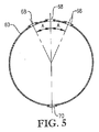
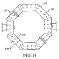
図1〜5を参照して、酸化剤スパージャー34の位置及び構造についてより詳細に記載する。図2及び3は、酸化剤スパージャー34がリング部材60、クロス部材62及び1対の酸化剤入口導管64a,bを含むことができることを示す。好都合なことには、図2及び3に示されるように、これらの酸化剤入口導管64a,bはリング部材60の上方の高さで容器に入り、次いで下向きに転じる。或いは、酸化剤入口導管64a,bはリング部材60の下方で又はリング部材の60と概ね同じ水平面で容器に入ることができる。各酸化剤入口導管64a,bは、容器シェル22中に形成された、それぞれの酸化剤入口66a,bに連結される第1端と、リング部材60に流体連結される第2端を含む。リング部材60は、好ましくは導管から、より好ましくは複数の直導管部分から、最も好ましくは互いに堅固に連結されて複数の管状多角形リングを形成する複数の直導管部分から形成される。好ましくはリング部材60は、少なくとも3個の、より好ましくは6〜10個の、最も好ましくは8個のまっすぐなパイプ部分から形成される。従って、リング部材60が8個のパイプ部分から形成される場合には、それはほぼ八角形の形状を有する。クロス部材62は好ましくは、リング部材60の対向するパイプ部分の間において対角線上に伸び且つそれらに流体連結される実質的にまっすぐなパイプ部分から形成される。クロス部材62に用いられるパイプ部分は、リング部材60を形成するのに用いられるパイプ部分と実質的に同じ直径を有するのが好ましい。酸化剤入口導管64a,b、リング部材60及びクロス部材62を構成するパイプ部分は、約0.1m超の、より好ましくは約0.2〜約2mの範囲の、最も好ましくは0.25〜1mの範囲の公称直径を有するのが望ましい。おそらく図3に最もよく示されるように、リング部材60及びクロス部材62はそれぞれ、酸化剤流を反応ゾーン28に上向きに排出するための複数の上部酸化剤用開口部68を提供する。おそらく図4に最もよく示されるように、リング部材60及び/又はクロス部材62は、酸化剤流を反応ゾーン28に下向きに排出するための1個又はそれ以上の下部酸化剤用開口部70を提供することができる。下部酸化剤用開口部70は、リング部材60及び/又はクロス部材62内に浸入するかもしれない液体及び/又は固体を排出するのに用いることもできる。固体が酸化剤スパージャー34の内側に沈着するのを防ぐために、液体流を、連続的又は定期的にスパージャー34に通して、堆積した固体を全て流し出すことができる。
The location and structure of the
再び図1〜4を参照すると、気泡塔型反応器20中における酸化の間に、酸化剤流は酸化剤入口66a,bを通してそれぞれ酸化剤入口導管64a,b中に押し込まれる。次いで、酸化剤流は、酸化剤入口導管64a,bを経てリング部材60に運搬される。酸化剤流がリング部材60に入ったら、酸化剤流はリング部材60及びクロス部材62の内部容積全体に分配される。次に、酸化剤流は、リング部材60及びクロス部材62の上部及び下部酸化剤用開口部68,70を経て酸化剤スパージャー34から出て反応ゾーン28中に押し込まれる。
1-4, during oxidation in the
上部酸化剤用開口部の出口68は、互いに横方向に間隔をあけて、反応ゾーン28の実質的に同じ高さに配置される。従って、上部酸化剤用開口部68の出口は、一般に酸化剤スパージャー34の頂部によって規定される実質的に水平な面に沿って位置する。下部酸化剤用開口部70の出口は、互いに横方向に間隔をあけて、反応ゾーン28の実質的に同じ高さに配置される。従って、下部酸化剤用開口部70の出口は、一般に酸化剤スパージャー34の底部によって規定される実質的に水平な面に沿って位置する。
The
本発明の一実施態様において、酸化剤スパージャー34には、少なくとも約20個の上部酸化剤用開口部が形成されている。より好ましくは、酸化剤スパージャー34には、約40〜約800個の範囲の上部酸化剤用開口部68が形成されている。最も好ましくは、酸化剤スパージャー34には、60〜400個の範囲の上部酸化剤用開口部68が形成されている。酸化剤スパージャー34には、好ましくは少なくとも約1個の下部酸化剤用開口部70が形成されている。より好ましくは、酸化剤スパージャー34には、約2〜約40個の範囲の下部酸化剤用開口部70が形成されている。最も好ましくは、酸化剤スパージャー34には、8〜20個の範囲の下部酸化剤用開口部70が形成されている。酸化剤スパージャー34における上部酸化剤用開口部68対下部酸化剤用開口部70の数の比は、好ましくは約2:1〜約100:1、より好ましくは約5:1〜約25:1、最も好ましくは8:1〜15:1の範囲である。上部及び下部酸化剤用開口部68、70から出る酸化剤流の体積流速の比が上部及び下部酸化剤用開口部68、70の相対数に関する前述の比と実質的に同じとなるように、実質的に全ての上部及び且つ酸化剤用開口部68、70の直径は好ましくは実質的に同じである。
In one embodiment of the present invention, the
図5は、上部及び下部酸化剤用開口部68、70からの酸化剤排出の方向を示す。上部酸化剤用開口部68に関しては、上部酸化剤用開口部68の少なくとも一部が、垂線から斜めに角度Aで酸化剤流を排出するのが好ましい。垂線から角度Aだけ傾斜している上部酸化材料開口部68の百分率は、約30〜約90%の範囲、より好ましくは約50〜約80%の範囲、更に好ましくは60〜75%の範囲、最も好ましくは67%であるのが望ましい。角度Aは、好ましくは約5〜約60°、より好ましくは約10〜約45°、最も好ましくは15〜30°の範囲である。下部酸化剤用開口部70に関しては、下部酸化剤用開口部70の実質的に全てがリング部材60及び/又はクロス部材62の最下部近くに位置する。従って、酸化剤スパージャー34中に誤って入る可能性がある全ての液体及び/又は固体は、下部酸化剤用開口部70を経て酸化剤スパージャー34から容易に排出させることができる。好ましくは、下部酸化剤用開口部70は、酸化剤流を実質的に垂直な角度で下向きに排出する。この説明のためには、上部酸化剤用開口部は、酸化剤流を概ね上向きに(即ち、水平面より上の角度で)排出する任意の開口部であることができ、下部酸化剤用開口部は、酸化剤流を概ね下向きに(即ち、水平より下の角度で)排出する任意の開口部であることができる。
FIG. 5 shows the direction of oxidant discharge from the upper and
多相反応媒体を含む多くの従来型の気泡塔型反応器においては、酸化剤スパージャー(又は酸化剤流を反応ゾーン中に導入する他のメカニズム)より下に位置する反応媒体の実質的に全てが非常に低いガス・ホールドアップ値を有する。当業界で知られる通り、「ガス・ホールドアップ」は単に、気体状態の多相媒体の体積分率である。媒体中のガス・ホールドアップの低いゾーンは、「無通気」ゾーンと称することもできる。多くの従来型のスラリー気泡塔型反応器においては、反応媒体の総容量のかなりの部分が、酸化剤スパージャー(又は酸化剤流を反応ゾーン中に導入する他のメカニズム)より下に位置する。従って、従来型の気泡塔型反応器の底部に存在する反応媒体のかなりの部分が無通気である。 In many conventional bubble column reactors that include a multiphase reaction medium, the reaction medium substantially below the oxidant sparger (or other mechanism for introducing an oxidant stream into the reaction zone). All have very low gas holdup values. As is known in the art, “gas holdup” is simply the volume fraction of a gaseous multiphase medium. Zones with low gas hold-up in the media can also be referred to as “no vent” zones. In many conventional slurry bubble column reactors, a significant portion of the total volume of the reaction medium is below the oxidant sparger (or other mechanism that introduces the oxidant stream into the reaction zone). . Thus, a significant portion of the reaction medium present at the bottom of a conventional bubble column reactor is airless.
気泡塔型反応器中で酸化に供される反応媒体中の無通気ゾーンの量を最小限に抑えると、いくつかの型の不所望な不純物の発生を最小限に抑えることができることを発見した。反応媒体の無通気ゾーンに含まれる酸化剤気泡は比較的少ない。この低容積の酸化剤気泡は、反応媒体の液相中に溶解させるのに利用できる分子状酸素の量を減少させる。従って、反応媒体の無通気ゾーン中の液相中の分子状酸素は比較的低濃度である。反応媒体のこれらの酸素が不足した無通気ゾーンは、望ましい酸化反応ではなく、不所望な副反応を促進する傾向がある。例えばp−キシレンを部分酸化してテレフタル酸を生成させる場合には、反応媒体の液相中における不充分な酸素利用可能性のため、安息香酸及び共役芳香環、とりわけ、フルレオノン類及びアントラキノン類として知られる、非常に不所望な有色分子が不所望に多量に形成される可能性がある。 It has been discovered that minimizing the amount of unvented zones in the reaction medium subjected to oxidation in a bubble column reactor can minimize the generation of some types of unwanted impurities. . Relatively few oxidant bubbles are contained in the aeration zone of the reaction medium. This low volume oxidant bubble reduces the amount of molecular oxygen available to dissolve in the liquid phase of the reaction medium. Accordingly, the molecular oxygen in the liquid phase in the non-vented zone of the reaction medium has a relatively low concentration. These oxygen-deficient non-vented zones of the reaction medium tend to promote undesirable side reactions rather than desirable oxidation reactions. For example, when p-xylene is partially oxidized to produce terephthalic acid, due to insufficient oxygen availability in the liquid phase of the reaction medium, as benzoic acid and conjugated aromatic rings, especially fluoreonones and anthraquinones Known and highly undesirable colored molecules can be formed in undesirably large amounts.
本発明の一実施態様によれば、液相酸化は、ガス・ホールドアップが低い反応媒体の体積分率を最小限に抑えられるように構成し且つ運転する気泡塔型反応中で実施する。このような無通気ゾーンの最小化は、反応媒体の全容積を均一容積の2,000個の水平スライスに理論的に分割することによって定量化することができる。最上部及び最下部の水平スライスを除いて、各水平スライスは、側面で反応器の側壁と境界を接し且つ頂部及び底部で仮想水平面と境界を接する別々の容積である。最上部の水平スライスは、底部で仮想水平面と境界を接し且つ頂部で反応媒体の上面と境界を接する。最下部の水平スライスは、頂部で仮想水平面と境界を接し且つ底部で容器の下端と境界を接する。反応媒体を、等容積の2,000個の別々の水平スライスに理論的に分割すると、各水平スライスの時間平均及び体積平均ガス・ホールドアップを算出することができる。無通気ゾーンの量のこの定量化法を用いる場合には、時間平均及び体積平均ガス・ホールドアップが0.1未満である水平スライスの数は、30個未満、より好ましくは15個未満、更に好ましくは6個未満、更に好ましくは4個未満、最も好ましくは2個未満であるのが望ましい。ガス・ホールドアップが0.2未満である水平スライスの数は、80個未満、より好ましくは40個未満、更に好ましくは20個未満、更に好ましくは12個未満、最も好ましくは5個未満であるのが望ましい。ガス・ホールドアップが0.3未満である水平スライスの数は、120個未満、より好ましくは80個未満、更に好ましくは40個未満、更に好ましくは20個未満、最も好ましくは15個未満であるのが望ましい。 According to one embodiment of the invention, the liquid phase oxidation is carried out in a bubble column type reaction configured and operated to minimize the volume fraction of the reaction medium having a low gas hold-up. Such aeration zone minimization can be quantified by theoretically dividing the total volume of the reaction medium into 2,000 horizontal slices of uniform volume. With the exception of the top and bottom horizontal slices, each horizontal slice is a separate volume that borders the reactor sidewalls at the sides and borders the virtual horizontal plane at the top and bottom. The top horizontal slice borders the virtual horizontal plane at the bottom and borders the top surface of the reaction medium at the top. The lowermost horizontal slice borders the virtual horizontal plane at the top and borders the lower end of the container at the bottom. If the reaction medium is theoretically divided into 2,000 separate horizontal slices of equal volume, the time average and volume average gas holdup for each horizontal slice can be calculated. When using this quantification method for the amount of aeration zone, the number of horizontal slices with a time average and volume average gas holdup of less than 0.1 is less than 30, more preferably less than 15, and even more Preferably it is less than 6, more preferably less than 4, most preferably less than 2. The number of horizontal slices with a gas hold-up less than 0.2 is less than 80, more preferably less than 40, even more preferably less than 20, more preferably less than 12, most preferably less than 5. Is desirable. The number of horizontal slices with a gas holdup of less than 0.3 is less than 120, more preferably less than 80, even more preferably less than 40, more preferably less than 20, most preferably less than 15. Is desirable.
再び図1及び2を参照すると、反応器ゾーン28中におけるより下方への酸化剤スパージャー34の配置には、反応媒体36中の無通気ゾーンの量の減少を含むいくつかの利点があることを発見した。反応媒体36の高さをH、反応ゾーン28の長さをL、反応ゾーン28の最大直径をDとすると、酸化剤流の大部分(即ち、>50重量%)が、反応ゾーン28の下端52の約0.025H、0.022L及び/又は0.25D以内の反応ゾーン28中に導入されるのが好ましい。より好ましくは、酸化剤流の大部分は、反応器ゾーン28の下端52の約0.02H、0.018L及び/又は0.2D以内の反応ゾーン28中に導入する。最も好ましくは、酸化剤流の大部分は、反応器ゾーン28の下端52の0.015H、0.013L及び/又は0.15D以内の反応ゾーン28中に導入する。
Referring again to FIGS. 1 and 2, the
図2に示される実施態様において、酸化剤流の実質的に全てが反応器ゾーン28の約0.25H、0.022L及び/又は0.25D以内の反応ゾーン28中に入るように、反応ゾーン28の下端52と酸化剤スパージャー34の上部酸化剤用開口部68の出口との間の垂直距離Y1は約0.25H、0.022L及び/又は0.25D未満である。より好ましくは、Y1は約0.02H、0.018L及び/又は0.2D未満である。最も好ましくは、Y1は0.015H、0.013L及び/又は0.15D未満であるが、0.005H、0.004L及び/又は0.06Dより大きい。図2は、容器シェル22の円筒形本体46の下縁部が容器シェル22の楕円形下部ヘッド48の上縁部と接する位置に接線72を示す。或いは、下部ヘッド48は、円錐形を含む任意の形状であることができ、接線はそれでも円筒形本体46の下縁部と定義される。接線72と酸化剤スパージャー34の頂部との間の垂直距離Y2は、好ましくは少なくとも約0.0012H、0.001L、及び/又は0.01D;より好ましくは少なくとも約0.005H、0.004L及び/又は0.05D;最も好ましくは少なくとも0.01H、0.008L及び/又は0.1Dである。反応ゾーン28の下端52と酸化剤スパージャー34の下部酸化剤用開口部70の出口との間の垂直距離Y3は、好ましくは約0.015H、0.013L及び/又は0.15D未満;より好ましくは約0.012H、0.01L及び/又は0.1D未満;最も好ましくは0.01H、0.008L及び/又は0.075D未満であるが0.003H、0.002L及び/又は0.025Dより大きい。
In the embodiment shown in FIG. 2, the reaction zone is such that substantially all of the oxidant stream enters
本発明の好ましい実施態様において、酸化剤流及び供給材料流を反応ゾーン中に排出する開口部は、開口部から排出される酸化剤又は供給材料流の量(重量基準で)が開口部の孔面積に正比例するように構成する。従って、例えば全ての酸化剤用開口部によって規定される累積孔面積の50%が反応ゾーンの底部の0.15D以内に位置する場合には、酸化剤流の50重量%が反応ゾーンの底部の0.15D以内の反応ゾーンに入り、逆の場合も同じである。 In a preferred embodiment of the present invention, the opening for discharging the oxidant stream and the feed stream into the reaction zone has an opening in which the amount of oxidant or feed stream discharged from the opening (by weight) is a hole in the opening. It is configured to be directly proportional to the area. Thus, for example, if 50% of the cumulative pore area defined by all oxidant openings is located within 0.15D of the bottom of the reaction zone, 50% by weight of the oxidant stream is at the bottom of the reaction zone. Enter the reaction zone within 0.15D and vice versa.
反応媒体36中の無通気ゾーン(即ち、ガス・ホールドアップの低いゾーン)を最小限に抑えることによって提供される利点に加えて、全反応媒体36のガス・ホールドアップを最大にすることによって酸化を増大できることを発見した。反応媒体36は時間平均及び体積平均ガス・ホールドアップが、好ましくは少なくとも約0.4、より好ましくは約0.6〜約0.9の範囲、最も好ましくは0.65〜0.85の範囲である。気泡塔型反応器20のいくつかの物理的な及び操作上の属性が、前述の高いガス・ホールドアップに寄与する。例えば、所与の反応器サイズ及び酸化剤流の流れに関しては、反応ゾーン28の高いL:D比がより短い直径を与え、それが反応媒体36中の空塔速度を増大させ、その結果、ガス・ホールドアップが増大する。更に、所与の一定空塔速度として考えても、気泡塔の実直径及びL:D比が平均ガス・ホールドアップに影響を及ぼすことがわかっている。また、無通気ゾーンの最小化(特に、反応ゾーン28の底部において)が、ガス・ホールドアップの増大に寄与する。更にまた、気泡塔型反応器の塔頂圧及び機械的構造が、ここに開示した高い空塔速度及びガス・ホールドアップ値において運転安定性に影響を及ぼす可能性がある。
In addition to the benefits provided by minimizing the no-aeration zone (ie, the zone with low gas hold-up) in the
更に、本発明者らは、ガス・ホールドアップ及び物質移動を増加させるには、最適化された塔頂圧で運転することが重要であることを発見した。より低い塔頂圧での運転は、ヘンリーの法則の作用に従って、分子状酸素の溶解度を減少させるので、気体から液体への分子状酸素の物質移動速度を低下させように見えるかもしれない。機械的撹拌容器の場合には、通気レベル及び物質移動速度が撹拌機の設計及び塔頂圧によって左右されるので典型的にそうである。しかし、本発明の好ましい実施態様に係る気泡塔型反応器においては、より低い塔頂圧を用いて一定の質量の気相酸化剤流により大きい容積を占めさせることによって、反応媒体36中の空塔速度を増加させ、更にはガス・ホールドアップ及び分子状酸素の移動速度を増加させる方法が発見された。
In addition, the inventors have discovered that it is important to operate at an optimized top pressure to increase gas holdup and mass transfer. Operating at a lower overhead pressure may appear to reduce the mass transfer rate of molecular oxygen from gas to liquid, as it reduces the solubility of molecular oxygen according to the action of Henry's law. In the case of mechanically stirred vessels, this is typically the case because the aeration level and mass transfer rate depend on the stirrer design and top pressure. However, in a bubble column reactor according to a preferred embodiment of the present invention, a lower mass pressure is used to occupy a larger volume in a constant mass gas phase oxidant stream, thereby reducing the empty space in the
気泡の融合と分割とのバランスは極めて複雑な現象である。この現象は、一方では、泡立つ傾向につながり、それは液相の内部循環速度を低下させると共に、極めて大きい離脱ゾーンが必要とする可能性があり、他方では、数の少ない非常に大きい気泡を生じる傾向につながり、それはガス・ホールドアップを低下させ且つ酸化剤流から液相への物質速度を低下させる。液相に関しては、中でも、その組成、密度、粘度及び表面張力が非常に複雑な方法で相互作用して、固相がない場合でさえ非常に複雑な結果を生じることが知られている。例えば、実験室の研究者は、簡単な水−空気気泡塔の場合でさえ、観察結果を報告及び評価する場合に、「水」が水道水、蒸留水又は脱イオン水のいずれであるかを限定することが有用であることに気付いている。液相中の複雑な混合物に関して及び固相の添加に関しては、複雑さの程度が更に増す。どのような泡立ち挙動及び自然対流のフローパターンが起こるかを立証する上で、とりわけ、固体の個々の粒子の表面不整、固体の平均サイズ、粒度分布、液相に対する固体の量及び液体が固体表面を湿潤させる能力の全てが、液相及び酸化剤流との相互作用で重要である。 The balance between bubble fusion and division is a very complex phenomenon. This phenomenon, on the one hand, leads to a tendency to foam, which reduces the internal circulation rate of the liquid phase and may require a very large detachment zone, on the other hand, tends to produce a very small number of very small bubbles. Which reduces gas hold-up and reduces the material velocity from the oxidant stream to the liquid phase. With respect to the liquid phase, it is known, among other things, that its composition, density, viscosity and surface tension interact in very complex ways, producing very complex results even in the absence of a solid phase. For example, a laboratory researcher may determine whether "water" is tap water, distilled water or deionized water when reporting and evaluating observations, even in the case of a simple water-air bubble column. I find it useful to limit. For complex mixtures in the liquid phase and for the addition of solid phases, the degree of complexity is further increased. In demonstrating what foaming behavior and natural convection flow patterns occur, among other things, the surface irregularity of the solid individual particles, the average size of the solids, the particle size distribution, the amount of solids relative to the liquid phase and the liquid All of the ability to wet is important in the interaction with the liquid phase and the oxidant stream.
従って、気泡塔型反応器が、ここに開示した高い空塔速度及び高いガス・ホールドアップで有効に機能できるか否かは、例えば、以下を適切に選択することにかかっている:(1)反応媒体の液相の組成;(2)沈殿固体の量及び型(いずれも、反応条件によって調整できる);(3)反応器に供給される酸化剤流の量;(4)酸化剤流の体積流量、気泡の安定性及び(エネルギー収支による)反応温度に影響を及ぼす塔頂圧;(5)流体の性質、沈澱固体の性質及び酸化剤流の比体積に影響を及ぼす反応温度自体;並びに(6)L:D比を含む、反応器の形状寸法及び機械的細部。 Thus, whether a bubble column reactor can function effectively with the high superficial velocity and high gas holdup disclosed herein, for example, depends on the appropriate choice of: (1) Composition of the liquid phase of the reaction medium; (2) amount and type of precipitated solids (both can be adjusted by reaction conditions); (3) amount of oxidant stream fed to the reactor; (4) oxidant stream Overhead pressure affecting volumetric flow rate, bubble stability and reaction temperature (due to energy balance); (5) reaction temperature itself affecting fluid properties, properties of precipitated solids and specific volume of oxidant stream; and (6) Reactor geometry and mechanical details, including L: D ratio.
再び図1を参照すると、反応媒体36中における被酸化性化合物(例えばp−キシレン)の改善された分布は、垂直方向に間隔をあけて配置された複数の位置で反応ゾーン28中に液相供給流を導入することによって提供することができることを発見した。好ましくは、液相供給流は、反応ゾーン28中に少なくとも3つの、より好ましくは少なくとも4つの供給開口部を経て導入する。ここで使用する用語「供給開口部(feed openings)」は、液相供給流が、反応媒体36との混合のために、反応ゾーン28中に排出される開口部を意味するものとする。少なくとも2つの供給開口部が、互いに垂直に少なくとも約0.5D、より好ましくは少なくとも約1.5D、最も好ましくは少なくとも3Dの間隔をあけて配置されるのが望ましい。しかし、最上部の供給開口部は、最下部の酸化剤用開口部から垂直に約0.75H、0.65L及び/又は8D以下;より好ましくは約0.5H、0.4L及び/又は5D以下;最も好ましくは0.4H、0.35L及び/又は4D以下の間隔をあけて配置されるのが望ましい。
Referring again to FIG. 1, the improved distribution of the oxidizable compound (eg, p-xylene) in the
液相供給流を複数の垂直位置において導入するのが望ましいが、反応媒体36中における被酸化性化合物の改善された分布は、液相供給流の大部分が反応媒体36及び/又は反応ゾーン28の下半分に導入する場合に提供されることも発見した。好ましくは、液相供給流の少なくとも約75重量%を、反応媒体36及び/又は反応ゾーン28の下半分に導入する。最も好ましくは、液相供給流の少なくとも90重量%を、反応媒体36及び/又は反応ゾーン28の下半分に導入する。更に、液相供給流の少なくとも約30重量%を、酸化剤流が反応ゾーン28に供給される最も低い垂直位置の約1.5D以内において反応ゾーン28中に導入するのが好ましい。酸化剤流が反応ゾーン28に導入されるこの最も低い垂直位置は典型的には酸化剤スパージャーの底部であるが、酸化剤流を反応ゾーン28に導入するための種々の代替構造も、本発明の好ましい実施態様によって考慮される。好ましくは、液相供給流の少なくとも約50重量%を、酸化剤流が反応ゾーン28に導入される最も低い垂直位置の約2.5D以内に導入する。好ましくは、液相供給流の少なくとも約75重量%を、酸化剤流が反応ゾーン28に導入される最も低い垂直位置の約5D以内に導入する。
Although it is desirable to introduce the liquid phase feed stream at a plurality of vertical positions, the improved distribution of oxidizable compounds in the
各供給開口部は、それを通して供給材料が排出される孔面積を規定する。全供給口の累積孔面積の少なくとも約30%が、酸化剤流が反応ゾーン28に導入される最も低い垂直位置の約1.5D以内に位置するのが好ましい。好ましくは、全供給口の累積孔面積の少なくとも約50%が、酸化剤流が反応ゾーン28に導入される最も低い垂直位置の約2.5D以内に位置する。好ましくは、全供給口の累積孔面積の少なくとも約75%が、酸化剤流が反応ゾーン28に導入される最も低い垂直位置の約5D以内に位置する。
Each feed opening defines a hole area through which feed material is discharged. Preferably, at least about 30% of the cumulative pore area of all feeds is located within about 1.5D of the lowest vertical position where the oxidant stream is introduced into the reaction zone. Preferably, at least about 50% of the cumulative pore area of all feed ports is located within about 2.5D of the lowest vertical position where the oxidant stream is introduced into the
再び図1を参照すると、本発明の一実施態様において、供給口32a、b、c、dは単に、容器シェル22の一側に沿って垂直方向に並べられた開口部である。これらの供給開口部は好ましくは約7cm未満の、より好ましくは約0.25〜約5cmの範囲の、最も好ましくは0.4〜2cmの範囲の実質的に同様な直径を有する。気泡塔型反応器20には、好ましくは各供給開口部から出る液相供給流の流速を調整するためのシステムが装着される。このような流量調整システムは好ましくは、個別の供給口32a、b、c、dのそれぞれに対して個別の流量調整弁74a、b、c、dを含む。更に、気泡塔型反応器20中には、液相供給流の少なくとも一部を少なくとも約2m/秒の、より好ましくは約5m/秒の、更に好ましくは少なくとも約6m/秒の、最も好ましくは8〜20m/秒の範囲の高い入口空塔速度で反応ゾーン28に導入させる流量調整システムが装着されるのが望ましい。ここで使用する用語「入口空塔速度」は、(供給開口部から出る供給流の時間平均体積流速)÷(供給開口部の面積)を意味する。好ましくは、供給流の少なくとも約50重量%が高い入口空塔速度で反応ゾーン28に導入される。最も好ましくは、供給流の実質的に全てが高い入口空塔速度で反応ゾーン28に導入される。
Referring again to FIG. 1, in one embodiment of the present invention, the supply ports 32 a, b, c, d are simply openings arranged vertically along one side of the
図6〜7を参照すると、液相供給流を反応ゾーン28に導入するための代替システムが示されている。この実施態様においては、供給流は4つの異なった高さで反応ゾーン28に導入される。各高さには、個別の供給分配システム76a、b、c、dが装着される。各供給分配システム76は、主供給導管78とマニホールド80を含む。各マニホールド80は容器シェル22の反応ゾーン28中に伸びる個別のインサート導管86、88に連結された少なくとも2つの出口82、84を具備する。各インサート導管86、88は、反応ゾーン28中に供給流を排出するための個別の供給開口部87、89を提供する。供給開口部87、89は好ましくは約7cm未満の、より好ましくは約0.25〜約5cmの範囲の、最も好ましくは0.4〜2cmの範囲の実質的に同様な直径を有する。各供給分配システム76a、b、c、dの供給開口部87、89は、供給流を反応ゾーン28中に反対の向きで導入するように対角線上に配置するのが好ましい。更に、隣接する供給分配システム76の対角線上に配置された供給開口部86、88は、互いに90°回転した位置に配置するのが好ましい。運転中には、液相供給流は主供給導管78に装入され、引き続いてマニホールド80に入る。マニホールド80は、供給開口部87、89を介して反応器20の正反対の2つの側において同時に導入するために、供給流を均等に分配する。
With reference to FIGS. 6-7, an alternative system for introducing a liquid phase feed stream into the
図8は、各供給分配システム76に、インサート導管86、88(図7に図示)ではなく、バヨネットチューブ(bayonet tube)90、92が装着された代替構造を示す。バヨネットチューブ90、92は反応ゾーン28中に突き出ており、液相供給材料を反応ゾーン28に排出するための多数の小さい供給開口部94、96を含む。バヨネットチューブ90、92のこの小さい供給開口部94、96は、約50mm未満、より好ましくは約2〜約25mmの、最も好ましくは4〜15mmの実質的に同一の直径を有するのが望ましい。
FIG. 8 shows an alternative construction in which each supply distribution system 76 is fitted with
図9〜11は、代替供給分配システム100を示す。供給分配システム100は、気泡塔型反応器20の側壁の多数の貫通を必要とせずに、垂直方向にも横方向にも間隔をあけられた複数の位置で液相供給流を導入する。供給導入システム100は、一般に単一の入口導管102、ヘッダー104、複数の直立分配管106、横支持機構108及び縦支持機構110を含む。入口導管102は容器シェル22の本体46の側壁を貫通する。入口導管102はヘッダー104と流体連結される。ヘッダー104は入口導管102から受けた供給流を直立分配管106の間に均等に分配する。各分配管106は、供給流を反応ゾーン28に排出するための、垂直方向に間隔をあけて配置された複数の供給開口部112a、b、c、dを有する。横支持機構108は、各分配管106に連結され、分配管106の横方向の相対運動を抑える。縦支持機構110は、好ましくは横支持機構108に及び酸化剤スパージャー34の頂部に連結される。縦支持機構110は、反応ゾーン28中の分配管106の縦方向の動きを実質的に抑える。供給開口部112は、約50mm未満、より好ましくは約2〜約25mm、最も好ましくは4〜15mmの実質的に同一の直径を有するのが望ましい。図9〜11に示された供給分配システム100の供給開口部112の垂直方向の間隔は、図1の供給分配システムに関して、前述したのと実質的に同じであることができる。
9-11 illustrate an alternative
多くの気泡塔型反応器中の反応媒体のフローパターンは、被酸化性化合物が主として反応媒体の一側に沿って導入される場合には特に、反応媒体中における被酸化性化合物の不均一な方位角分配を可能できることが判明した。ここで使用する用語「方位角」は、反応ゾーンの直立延長軸の周囲の角又は間隔を意味する。ここで使用する「直立」は、垂線の45°以内を意味する。本発明の一実施態様において、被酸化性化合物(例えばp−キシレン)を含む供給流は、方位角に間隔をあけて配置された複数の供給開口部を経て反応ゾーンに導入する。これらの方位角に間隔をあけて配置された供給開口部は、反応媒体中における過度に高い及び過度に低い被酸化性化合物濃度の領域を防ぐのに役立つことができる。図6〜11に示された種々の供給導入システムは、供給開口部の適正な方位角間隔を提供するシステムの例である。 The flow pattern of the reaction medium in many bubble column reactors is uneven, especially when the oxidizable compound is introduced mainly along one side of the reaction medium. It was found that azimuth distribution is possible. As used herein, the term “azimuth” refers to the angle or spacing around the upright extension axis of the reaction zone. As used herein, “upright” means within 45 ° of the perpendicular. In one embodiment of the present invention, a feed stream comprising an oxidizable compound (eg, p-xylene) is introduced into the reaction zone through a plurality of feed openings spaced at azimuth angles. Feed openings spaced at these azimuthal angles can help prevent regions of excessively high and excessively low oxidizable compound concentrations in the reaction medium. The various feed introduction systems shown in FIGS. 6-11 are examples of systems that provide proper azimuthal spacing of the feed openings.
再び図7を参照すると、液相供給材料流の反応媒体中への、方位角に間隔をあけられた導入を定量化するために、反応媒体を、ほぼ等容積の直立方位角クアドラント(quadrant)Q1、Q2、Q3、Q4に理論的に分割することができる。これらの方位角クアドラントQ1、Q2、Q3、Q4は、反応媒体の最大縦寸法及び最大半径方向寸法を越えて広がる1対の仮想上の直交する交差垂直面P1、P2によって規定される。反応媒体が円筒容器に含まれる場合には、仮想交差垂直面P1、P2の交線は円筒の垂直中心線とほぼ一致し、各方位角クアドラントQ1、Q2、Q3、Q4は、反応媒体の高さに等しい高さを有するほぼくさび形の垂直容積であろう。被酸化性化合物の相当部分が、少なくとも2つの異なる方位角クアドラント中に位置する供給開口部を経て反応媒体中に排出されるのが好ましい。 Referring again to FIG. 7, in order to quantify the azimuthally spaced introduction of the liquid phase feed stream into the reaction medium, the reaction medium is divided into approximately equal volume square cube angle quadrants. It can be divided theoretically into Q 1 , Q 2 , Q 3 and Q 4 . These azimuth quadrants Q 1 , Q 2 , Q 3 , Q 4 are defined by a pair of imaginary orthogonal intersecting vertical planes P 1 , P 2 that extend beyond the maximum longitudinal dimension and the maximum radial dimension of the reaction medium. It is prescribed. When the reaction medium is contained in a cylindrical container, the intersection line of the virtual intersecting vertical planes P 1 and P 2 substantially coincides with the vertical center line of the cylinder, and each azimuth quadrant Q 1 , Q 2 , Q 3 , Q 4 Will be a substantially wedge-shaped vertical volume with a height equal to the height of the reaction medium. A substantial portion of the oxidizable compound is preferably discharged into the reaction medium via feed openings located in at least two different azimuthal quadrants.
本発明の好ましい実施態様においては、被酸化性化合物の約80重量%以下が、単一の方位角クアドラント中に位置することができる供給開口部を通して反応媒体中に排出される。より好ましくは、被酸化性化合物の約60重量%以下が、単一の方位角クアドラント中に位置することができる供給開口部を通して反応媒体中に排出される。最も好ましくは、被酸化性化合物の40重量%以下が、単一の方位角クアドラント中に位置することができる供給開口部を通して反応媒体中に排出される。被酸化性化合物の方位角分配に関するこれらのパラメーターは、方位角クアドラントが被酸化性化合物の最大化可能量が方位角クアドラントの1つに排出されているような方位角に向けられた場合に、測定する。例えば、全供給流を、互いに方位角で89°の間隔をあけて配置された2つの供給開口部を経て反応媒体中に排出される場合には、4つの方位角クアドラントにおける方位角分配を測定するために、供給液の100重量%が単一の方位角クアドラントの反応媒体中に排出させる。これは、方位角クアドラントが、両方の供給開口部が単一の方位角クアドラントに位置するような方位角に向けることができるためである。 In a preferred embodiment of the invention, up to about 80% by weight of the oxidizable compound is discharged into the reaction medium through feed openings that can be located in a single azimuthal quadrant. More preferably, up to about 60% by weight of the oxidizable compound is discharged into the reaction medium through feed openings that can be located in a single azimuthal quadrant. Most preferably, up to 40% by weight of the oxidizable compound is discharged into the reaction medium through feed openings that can be located in a single azimuthal quadrant. These parameters for the azimuthal distribution of an oxidizable compound are such that when the azimuth quadrant is directed to an azimuth such that the maximizable amount of oxidizable compound is discharged into one of the azimuthal quadrants, taking measurement. For example, if the entire feed stream is discharged into the reaction medium via two feed openings that are spaced azimuthally by 89 ° from each other, the azimuth distribution in four azimuth quadrants is measured. To do so, 100% by weight of the feed is discharged into a single azimuthal quadrant reaction medium. This is because the azimuth quadrant can be directed to an azimuth angle such that both supply openings are located in a single azimuth quadrant.
供給開口部の適正な方位角間隔に関連する利点に加えて、気泡塔型反応器中の供給開口部の適正な半径方向間隔も重要であり得ることを発見した。反応媒体中に導入される被酸化性化合物の相当部分が、容器の側壁から内側に向かって半径方向に間隔をあけて配置された供給開口部を経て排出されるのが好ましい。従って、本発明の一実施態様において、被酸化性化合物の相当部分は、反応ゾーンを規定する直立側壁から内側に向かって間隔をあけて配置された「好ましい半径方向供給ゾーン」に位置する供給開口部を経て反応ゾーンに入る。 In addition to the advantages associated with proper azimuthal spacing of feed openings, it has been discovered that proper radial spacing of feed openings in a bubble column reactor can also be important. It is preferred that a substantial part of the oxidizable compound introduced into the reaction medium is discharged from the side walls of the container through supply openings which are radially spaced inward. Thus, in one embodiment of the present invention, a substantial portion of the oxidizable compound is located in a “preferred radial feed zone” located inwardly spaced from the upstanding side walls defining the reaction zone. Enter the reaction zone through the section.
再び図7を参照すると、好ましい半径方向供給ゾーンFZは、反応ゾーン28中に中心がある、外径DOが0.9D(Dは反応ゾーン28の直径である)の理論的直立円筒の形をとることができる。従って、厚さ0.05Dの外環OAが、好ましい半径方向供給ゾーンFZと反応ゾーン28を規定する側壁の内側との間に規定される。この外環OAに位置する供給開口部によっては、被酸化性化合物が、ほとんど又は全く、反応ゾーン28に導入されないことが好ましい。
Referring again to FIG. 7, the preferred radial feed zone FZ is in the form of a theoretical upright cylinder centered in the
別の実施態様において、反応ゾーン28の中央には、被酸化性化合物が、ほとんど又は全く導入されないのが好ましい。従って、図8に示されるように、好ましい半径方向供給ゾーンFZは、反応ゾーン28に中心がある、外径DOが0.9Dで且つ内径DIが0.2Dの理論的直立環の形をとることができる。従って、この実施態様においては、直径が0.2Dの内筒ICが、好ましい半径方向供給ゾーンFZの中央から「切り取られる」。この内筒ICに位置する供給開口部によっては、被酸化性化合物が、ほとんど又は全く、反応ゾーン28中に導入されないのが好ましい。
In another embodiment, it is preferred that little or no oxidizable compound is introduced into the center of the
本発明の好ましい実施態様において、好ましい半径方向供給ゾーンが前述の円筒又は環の形状を有するか否かにかかわらず、被酸化性化合物の相当部分が、好ましい半径方向供給ゾーン中に位置する供給開口部を経て反応媒体36中に導入される。より好ましくは、被酸化性化合物の少なくとも約25重量%が、好ましい半径方向供給ゾーン中に位置する供給開口部を経て反応媒体36中に排出される。更に好ましくは、被酸化性化合物の少なくとも約50重量%が、好ましい半径方向供給ゾーン中に位置する供給開口部を経て反応媒体36中に排出される。最も好ましくは、被酸化性化合物の少なくとも75重量%が、好ましい半径方向供給ゾーン中に位置する供給開口部を経て反応媒体36中に排出される。
In a preferred embodiment of the invention, a feed opening in which a substantial portion of the oxidizable compound is located in the preferred radial feed zone, regardless of whether the preferred radial feed zone has the aforementioned cylindrical or ring shape. And then introduced into the
図7及び8に示される理論的方位角クアドラント及び理論的な好ましい半径方向供給ゾーンを液相供給流の分配に関して説明したが、気相酸化剤流の適正な方位角及び半径方向分配もまた、いくつかの利点を有することを発見した。従って、本発明の一実施態様においては、前に示した、液相供給流の方位角及び半径方向分配の説明を、気相酸化剤流が反応媒体36中に導入する方法にも適用する。
Although the theoretical azimuth quadrant and the theoretically preferred radial feed zone shown in FIGS. 7 and 8 have been described with respect to liquid phase feed stream distribution, proper azimuth and radial distribution of the gas phase oxidant stream is also It has been discovered that it has several advantages. Accordingly, in one embodiment of the present invention, the description of azimuth and radial distribution of the liquid phase feed stream provided above also applies to the method in which the gas phase oxidant stream is introduced into the
図12〜15を参照すると、代替酸化剤スパージャー200が、リング部材202及び1対の酸化剤入口導管204、206を一般に含むものとして示されている。図12〜15の酸化剤スパージャー200は、図1〜11の酸化剤スパージャー34と同様であるが、以下の3つの主な違いがある:(1)酸化剤スパージャー200は対角線のクロス部材を含まない;(2)リング部材202の上部は、酸化剤を上向きに排出する開口部を有さない;(3)酸化剤スパージャー200は、リング部材202の下部にはるかに多くの開口部を有する。
With reference to FIGS. 12-15, an
おそらく図14及び15に最もよく示されるように、酸化剤スパージャーリング202の底部は多数の酸化剤用開口部208を提供する。酸化剤用開口部208は、好ましくは酸化剤用開口部208によって規定される総孔面積の少なくとも約1%がリング部材202の中心線210(図15)の下方に位置するように構成される。ここで、中心線210は、リング部材202の体積中心の高さに位置する。より好ましくは、全酸化剤用開口部208によって規定される総孔面積の少なくとも約5%が中心線210の下方に位置し、総孔面積の少なくとも約2%が、垂線の約30°以内のほぼ下向きに酸化剤流を排出する開口部208によって規定されている。更に好ましくは、全酸化剤用開口部208によって規定される総孔面積の少なくとも約20%が中心線210の下方に位置し、総孔面積の少なくとも約10%が、垂線の約30°以内のほぼ下向きに酸化剤流を排出する開口部208によって規定されている。最も好ましくは、全酸化剤用開口部208によって規定される総孔面積の少なくとも約75%が中心線210の下方に位置し、総孔面積の少なくとも約40%が、垂線の約30°以内のほぼ下向きに酸化剤流を排出する開口部208によって規定されている。中心線210の上方に位置する全酸化剤用開口部208によって規定される総孔面積の割合は、好ましくは約75%未満、より好ましくは約50%未満、更に好ましくは約25%未満、最も好ましくは5%未満である。
Probably best shown in FIGS. 14 and 15, the bottom of the
図14及び15に示されるように、酸化剤用開口部208は、下向き開口部208a及び斜め開口部208bを含む。下向き開口部208aは、垂線の約30°以内の、より好ましくは垂線の約15°以内の、最も好ましくは垂線の5°以内の角度でほぼ下向きに酸化剤流を排出するように構成される。斜め開口部208bは、垂線から約15〜75°の範囲の角度Aでほぼ外側下向きに酸化剤流を排出するように構成される。より好ましくは、角度Aは、垂線から約30〜約60°の範囲であり、最も好ましくは角度Aは、垂線から40〜50°の範囲である。
As shown in FIGS. 14 and 15, the
実質的に全ての酸化剤用開口部208がほぼ同一の直径を有するのが好ましい。酸化剤用開口部208の直径は、好ましくは約2〜約300mm、より好ましくは約4〜約120mm、最も好ましくは8〜60mmの範囲である。リング部材202中の酸化剤用開口部208の総数は、以下に詳述する低圧力降下基準を満たすように選択される。好ましくは、リング部材202中に形成される酸化剤用開口部208の総数は、少なくとも10個、より好ましくは酸化剤用開口部208の総数は約20〜約200個の範囲、最も好ましくは酸化剤用開口部208の総数は40〜100個の範囲である。
It is preferred that substantially all
図12〜15は酸化剤スパージャー200の極めて特殊な構造を示すが、種々の酸化剤スパージャーの構造を用いて、ここに記載した利点を達成できることが注目される。たとえば、酸化剤スパージャーは、図12〜13に示される八角形のリング部材の構造を必ずしも有する必要はない。正しくは、酸化剤スパージャーは、酸化剤流を排出するための間隔をあけて配置された複数の開口部を使用する任意の構造の流通導管から形成されることが可能である。流通導管中の酸化剤用開口部の大きさ、数及び排出方向は好ましくは前述の範囲内である。更に、酸化剤スパージャーは好ましくは、前述の分子状酸素の方位角及び半径方向分配を提供するように構成される。
12-15 illustrate the very specific structure of the
酸化剤スパージャーの具体的な構造にかかわらず、酸化剤スパージャーは、流通導管から出て酸化剤用開口部を通って反応ゾーンにいたる酸化剤流の排出に付随する圧力降下を最小限に抑えるように構成され、運転するのが好ましい。このような圧力降下は、(酸化剤スパージャーの酸化剤入口66a、bにおける流通導管の内側の酸化剤流の時間平均静圧)−(酸化剤流の1/2がその垂直位置の上方に導入され且つ酸化剤流の1/2がその垂直位置の下方に導入される高さにおける反応ゾーン中の時間平均静圧)として計算される。本発明の好ましい実施態様において、酸化剤スパージャーからの酸化剤流の排出に付随する時間平均圧力降下は、約0.3メガパスカル(MPa)未満、より好ましくは約0.2MPa未満、更に好ましくは約0.1MPa未満、最も好ましくは0.05MPa未満である。ここに記載する気泡塔型反応器の好ましい運転条件下では、酸化剤スパージャーの流通導管の内側における酸化剤流の圧力は、好ましくは約0.35〜約1MPa、より好ましくは約0.45〜約0.85MPa、最も好ましくは0.5〜0.7MPaの範囲である。 Regardless of the specific structure of the oxidant sparger, the oxidant sparger minimizes the pressure drop associated with the discharge of the oxidant stream from the flow conduit and through the oxidant opening to the reaction zone. It is preferably configured and operated. Such a pressure drop is (time average static pressure of the oxidant flow inside the flow conduit at the oxidant inlet 66a, b of the oxidant sparger)-(1/2 of the oxidant flow above its vertical position). The time average static pressure in the reaction zone at the height at which half of the oxidant stream is introduced and below its vertical position is calculated. In a preferred embodiment of the present invention, the time average pressure drop associated with the discharge of the oxidant stream from the oxidant sparger is less than about 0.3 megapascal (MPa), more preferably less than about 0.2 MPa, even more preferably. Is less than about 0.1 MPa, most preferably less than 0.05 MPa. Under the preferred operating conditions of the bubble column reactor described herein, the pressure of the oxidant stream inside the oxidant sparger flow conduit is preferably about 0.35 to about 1 MPa, more preferably about 0.45. To about 0.85 MPa, most preferably in the range of 0.5 to 0.7 MPa.
図2〜5に示される酸化剤スパージャーの構造に関して前に言及したように、酸化剤スパージャーの固体による汚染を防ぐために、酸化剤スパージャーを液体(例えば酢酸、水及び/又はp−キシレン)で連続的に又は定期的にフラッシするのが望ましい場合がある。このような液体フラッシを用いる場合には、有効量の液体(即ち、酸化剤中にもともと存在するかもしれない微量の液滴だけでない)が、毎日少なくとも1分超の期間、酸化剤用開口部から酸化剤スパージャーに通すのが好ましい。液体が酸化剤スパージャーから連続的又は定期的に排出される場合には、(酸化剤スパージャーを通る液体の質量流速)対(酸化剤スパージャーを通る分子状酸素の質量流速)の時間平均比は約0.05:1〜約30:1、又は約0.1:1〜約2:1、又は更には0.2:1〜1:1の範囲であるのが好ましい。 As previously mentioned with respect to the structure of the oxidant sparger shown in FIGS. 2-5, the oxidant sparger can be liquid (eg, acetic acid, water and / or p-xylene) to prevent contamination of the oxidant sparger with solids. ) It may be desirable to flush continuously or periodically. When using such a liquid flash, an effective amount of liquid (i.e. not just a small amount of liquid droplets that may originally be present in the oxidant) is maintained for at least one minute each day for the oxidant opening. Through an oxidant sparger. Time average of (mass flow rate of liquid through oxidant sparger) versus (mass flow rate of molecular oxygen through oxidant sparger) versus time if liquid is drained continuously or periodically from oxidant sparger The ratio is preferably in the range of about 0.05: 1 to about 30: 1, or about 0.1: 1 to about 2: 1, or even 0.2: 1 to 1: 1.
本発明の一実施態様において、被酸化性化合物(例えばp−キシレン)の相当部分は、酸化剤スパージャーを通して反応ゾーン中に導入することができる。このような構造において、被酸化性化合物及び分子状酸素は、酸化剤スパージャー中の同じ開口部を通して酸化剤スパージャーから排出されるのが好ましい。前述のように、被酸化性化合物は典型的にはSTPにおいて液体である。従って、この実施態様において、液相が被酸化性化合物を含み且つ気相が分子状酸素を含む二相流を、酸化剤スパージャーから排出することができる。しかし、被酸化性化合物の少なくとも一部が、酸化剤スパージャーから排出される際に気体状態である可能性があることを認識しなければならない。一実施態様においては、酸化剤スパージャーから排出される液相は、主として被酸化性化合物から形成される。別の実施態様においては、酸化剤スパージャーから排出される液相は、前述の供給流と実質的に同一の組成を有する。酸化剤スパージャーから排出される液相が供給流と実質的に同一の組成を有する場合には、このような液相は溶媒及び/又は触媒系を、供給流の組成に関して前述した量及び比で含むことができる。 In one embodiment of the invention, a substantial portion of the oxidizable compound (eg, p-xylene) can be introduced into the reaction zone through an oxidant sparger. In such a structure, the oxidizable compound and molecular oxygen are preferably exhausted from the oxidant sparger through the same opening in the oxidant sparger. As mentioned above, the oxidizable compound is typically a liquid in STP. Thus, in this embodiment, a two-phase flow in which the liquid phase contains an oxidizable compound and the gas phase contains molecular oxygen can be discharged from the oxidant sparger. However, it must be recognized that at least a portion of the oxidizable compound may be in a gaseous state as it is discharged from the oxidant sparger. In one embodiment, the liquid phase discharged from the oxidant sparger is formed primarily from oxidizable compounds. In another embodiment, the liquid phase discharged from the oxidant sparger has substantially the same composition as the feed stream described above. If the liquid phase discharged from the oxidant sparger has substantially the same composition as the feed stream, such liquid phase may contain the solvent and / or catalyst system in the amounts and ratios described above for the feed stream composition. Can be included.
本発明の一実施態様において、反応ゾーン中に導入される全被酸化性化合物の少なくとも10重量%が酸化剤スパージャーを経て反応ゾーン中に導入されるのが好ましく、より好ましくは、被酸化性化合物の少なくとも約40重量%が酸化剤スパージャーを経て反応ゾーン中に導入され、最も好ましくは、被酸化性化合物の少なくとも80重量%が酸化剤スパージャーを経て反応ゾーン中に導入される。被酸化性化合物の全て又は一部が酸化剤スパージャーを経て反応ゾーン中に導入される場合には、反応ゾーン中に導入される全分子状酸素の少なくとも約10重量%が、同一酸化剤スパージャーを経て導入されるのが好ましく、より好ましくは、被酸化性化合物の少なくとも約40重量%が同一酸化剤スパージャーを経て反応ゾーン中に導入され、最も好ましくは、被酸化性化合物の少なくとも80重量%が同一酸化剤スパージャーを経て反応ゾーン中に導入される。被酸化性化合物のかなりの量が酸化剤スパージャーを経て反応ゾーン中に導入される場合には、1つ又はそれ以上の温度感知装置(例えば熱電対)が、酸化剤スパージャー中に配設されるのが好ましい。これらの温度センサーは、酸化剤スパージャー中の温度が危険なほど高くならないことを確実にするのを助けるために使用できる。 In one embodiment of the invention, it is preferred that at least 10% by weight of the total oxidizable compound introduced into the reaction zone is introduced into the reaction zone via an oxidant sparger, more preferably oxidizable. At least about 40% by weight of the compound is introduced into the reaction zone via the oxidant sparger, and most preferably at least 80% by weight of the oxidizable compound is introduced into the reaction zone via the oxidant sparger. When all or part of the oxidizable compound is introduced into the reaction zone via an oxidant sparger, at least about 10% by weight of the total molecular oxygen introduced into the reaction zone is the same oxidant spur. Preferably, it is introduced via a jar, more preferably at least about 40% by weight of the oxidizable compound is introduced into the reaction zone via the same oxidant sparger, and most preferably at least 80% of the oxidizable compound. % By weight is introduced into the reaction zone via the same oxidant sparger. If a significant amount of oxidizable compound is introduced into the reaction zone via the oxidant sparger, one or more temperature sensing devices (eg, thermocouples) are disposed in the oxidant sparger. Preferably it is done. These temperature sensors can be used to help ensure that the temperature in the oxidant sparger does not become dangerously high.
図16〜18を参照すると、気泡塔型反応器20が、スラリー出口38近くの反応ゾーン28の底部に配設された内部脱気容器300を含むものとして示されている。反応媒体36の脱気時には比較的速い速度で不純物形成副反応が起こることを発見した。ここで使用する用語「脱気」は、多相反応媒体からの気相の離脱を意味するものとする。反応媒体36が非常によく通気されている(ガス・ホールドアップ>0.3)場合には、不純物の形成はごく少ない。反応媒体36が非常に無通気である(<ガス・ホールドアップ<0.01)場合には、不純物の形成はやはりごく少ない。しかし、反応媒体が部分通気される(ガス・ホールドアップ0.01〜0.3)場合には、不所望な副反応が促進され、不純物の発生が増加する。脱気容器300は、部分通気された状態にある反応媒体36の容量を最小限に抑えることによって、また、反応媒体36の脱気に要する時間を最小限に抑えることによって、この問題及び他の問題に対処する。実質的に脱気されたスラリーが、脱気容器300の底部から生成され、スラリー出口38を経て反応器20から出る。実質的に脱気されたスラリーは、好ましくは約5容量%未満、より好ましくは約2容量%、最も好ましくは1容量%の気相を含む。
With reference to FIGS. 16-18,
図16において、気泡塔型反応器20は、液面調節器302及び流量調節弁304を含むものとして示されている。液面調節器302及び流量調節弁304は協力して、反応媒体36を反応ゾーン28中の実質的に一定の高さに保持する。液面調節器302は、反応媒体36の上面44の高さを感知し(例えば差圧レベル式液面感知又は核(nuclear)液面感知による)、反応媒体36の高さに応答して調節信号306を生じるように作動する。流量調節弁304は、調節信号306を受けて、スラリー出口導管308を通るスラリーの流量を調節する。従って、スラリー出口38から出るスラリーの流速は、反応媒体36の高さが高すぎる場合の最大スラリー体積流速(Fmax)と反応媒体36の高さが低すぎる場合の最小スラリー体積流速(Fmin)との間で変動することができる。
In FIG. 16, the
反応ゾーン28から固相酸化生成物を除去するためには、一部分を最初に脱気容器300に通す必要がある。脱気容器300は、液体及び固体がスラリー出口38に向かって下向きに流れるにつれて、反応媒体36の気相を反応媒体36の液相及び固相から自然に上昇させる低乱流の内容積を生じる。液相及び固相からの気相の上昇は、液相及び固相の気相の自然の上向き浮揚性による。脱気容器300が用いられる場合には、充分に通気された三相媒体から充分に脱気された二相スラリーへの反応媒体36の遷移が速く且つ効率的である。
In order to remove the solid phase oxidation product from the
図17及び18を参照すると、脱気容器300は、間の脱気ゾーン312を規定するほぼ直立の側壁308を含む。好ましくは、側壁308は、垂線の約30°以内で、より好ましくは垂線の約10°以内で上向きに伸びる。最も好ましくは、側壁308は実質的に垂直である。脱気ゾーン312は、反応ゾーンとは分かれており、高さh及び直径dを有する。側壁308の上端310は、反応ゾーン28から内容積312中に反応媒体を受けるように開かれている。側壁308の下端は、遷移部314を経てスラリー出口38に液体連結されている。スラリー出口38の開口部が大きい場合又は側壁308の直径dが小さい場合のようないくつかの場合には、遷移部314は排除されることができる。おそらく図18に最もよく示されるように、脱気容器300はまた、脱気ゾーン312に配設されたボルテックスブレーカー316を含むことができる。ボルテックスブレーカー316は、固相及び液相がスラリー出口38に向かって下向きに流れる際の渦の形成を妨ぐように作動する。
With reference to FIGS. 17 and 18, the
脱気容器300中における固相及び液相からの気相の適切な離脱を可能にするためには、内部脱気ゾーン312の高さh及び水平断面積が慎重に選ばれる。スラリーの最大量が回収されている場合(即ち、スラリーがFmaxで回収されている場合)であっても、気泡が脱気容器300の底部出口に達する前に気泡容積の実質的に全てが固相及び気相から上昇できるように、内部脱気ゾーン312の高さh及び水平断面積は充分な距離及び時間を提供しなければならない。従って、脱気ゾーン312の断面積は、脱気ゾーン312を通る液相及び固相の最大下向き速度(Vdmax)が、液相及び固相を通る気相気泡の自然上昇速度(Vu)よりもかなり小さいのが好ましい。脱気ゾーン312を通る液相及び固相の最大下向き速度(Vdmax)は、前述の最大スラリー体積流量(Fmax)において起こる。液相及び固相を通る気泡の自然上昇速度(Vu)は、気泡の大きさによって異なるが;液相及び固相を通る直径0.5cmの気泡の自然上昇速度(Vu0.5)を、カットオフ値として使用できる。これは、反応媒体36中に最初に存在する気泡容積の実質的に全てが0.5cmより大きいためである。脱気ゾーン312の断面積は、VdmaxがVu0.5の約75%未満であるようにするのが好ましく、VdmaxがVu0.5の約40%未満であるようにするのがより好ましく、VdmaxがVu0.5の20%未満であるようにするのが最も好ましい。
In order to allow proper separation of the gas phase from the solid and liquid phases in the
脱気容器300の脱気ゾーン312中の液相及び固相の下向き速度は、(スラリー出口38を通る脱気スラリーの体積流速)÷(脱気ゾーン312の最小断面積)として計算される。脱気容器300の脱気ゾーン312中の液相及び固相の下向き速度は好ましくは約50cm/秒未満、より好ましくは約30cm/秒未満、最も好ましくは10cm/秒未満である。
The downward velocity of the liquid and solid phases in the
脱気容器300の直立側壁308は円筒の形状を有するものとして示されているが、側壁308は、それが適当な容積、断面積、幅d及び高さhを有する内容積を規定するならば、種々の形状(例えば三角形、正方形又は楕円形)をなす多数の側壁を含むことができるであろうことがわかる。本発明の好ましい実施態様において、dは、約0.2〜約2m、より好ましくは約0.3〜約1.5m、最も好ましくは0.4〜1.2mの範囲である。本発明の好ましい実施態様において、hは、約0.3〜約5m、より好ましくは約0.5〜約3m、最も好ましくは0.75〜2mの範囲である。
Although the
本発明の好ましい実施態様において、脱気ゾーン312の水平断面積積が脱気ゾーン312の全高hに沿って実質的に一定であるように、側壁308は実質的に垂直である。好ましくは、脱気ゾーン312の最大水平断面積は、反応ゾーン28の最大水平断面積の約25%未満である。より好ましくは、脱気ゾーン312の最大水平断面積は、反応ゾーン28の最大水平断面積の約0.1〜約10%の範囲である。最も好ましくは、脱気ゾーン312の最大水平断面積は、反応ゾーン28の最大水平断面積の0.25〜4%の範囲である。脱気ゾーン312の最大水平断面積は、好ましくは約0.02〜約3m2、より好ましくは約0.05〜約2m2、最も好ましくは0.1〜1.2m2の範囲である。脱気ゾーン312の容積は、好ましくは反応媒体36又は反応ゾーン28の総容積の約5%未満である。より好ましくは、脱気ゾーン312の容積は、反応媒体36又は反応ゾーン28の総容積の約0.01〜約2%の範囲である。最も好ましくは、脱気ゾーン312の容積は、反応媒体36又は反応ゾーン28の総容積の0.05〜約1%の範囲である。脱気ゾーン312の容積は、好ましくは約2m3未満、より好ましくは約0.01〜約1m3の範囲、最も好ましくは0.05〜0.5m3の範囲である。
In the preferred embodiment of the present invention, the
図19を参照すると、気泡塔型反応器20は、外部脱気容器400を含むのとして示されている。この構造においては、通気された反応媒体36が、容器シェル22の側部の高置開口部を経て反応ゾーン28から回収される。回収された通気媒体は、固相及び液相からの気相の離脱のために、外部導管402を経て外部脱気容器400に運搬される。離脱気相が導管404を経て脱気容器400から出る一方、実質的に脱気されたスラリーは導管406を経て脱気容器400から出る。
Referring to FIG. 19, the
図19において、出口導管402は、ほぼまっすぐで、水平で、容器シェル22に直交するものとして示されている。これは単に1つの都合のよい構造に過ぎず;出口導管402は、気泡塔型反応器20を外部脱気容器400に有効に接続するのであれば、いずれの点においても異なっていてもよい。導管404に目を転ずると、被酸化性化合物及び酸化剤を含む、淀んだガスポケットに関する安全性の問題をコントロールするために、この導管は、脱気容器400の頂部又はその近くで接続されるのが有益である。更に、導管402及び404は、バルブのような流れ分離手段を有効に含むことができる。
In FIG. 19, the
図19に示されるように、反応媒体36が高い位置の出口(elevated outlet)を経て反応器20から回収される場合には、気泡塔型反応器20には、反応ゾーン28の底部52近くに下部出口408が装着されるのが好ましい。下部出口408及びこれに連結された下部導管410は、運転停止の間に反応器20をデインベントリーする(deinnventory)(即ち、空にする)のに使用できる。好ましくは、1つ又はそれ以上の下部出口408が、反応媒体36の高さの下1/3に、より好ましくは反応媒体36の下1/4に、最も好ましくは反応媒体の最も低い点に設けられる。
As shown in FIG. 19, when the
図19に示される高い位置のスラリー回収及び脱気システムの場合には、下部導管410及び出口408は、酸化の間に反応ゾーン28からスラリーを回収するのには用いられない。淀んだ流通導管を含む、スラリーの無通気及びそうでなければ撹拌されていない部分において、固形分は重力によって沈降する傾向があることが当業界で知られている。更に、沈降固体(例えばテレフタル酸)は、沈澱及び/又は結晶再編成を続けることによって大きい凝集塊の状態に固まる傾向があり得る。従って、下部流通導管410の目詰まりを回避するために、反応器20の通常運転の間に、脱気容器400の底部からの脱気スラリーをわずかに用いて、下部導管410が連続的に又は断続的にフラッシされることができる。導管410にこのようなフラッシを提供するための好ましい手段は、導管410中のバルブ412を定期的に開き、ごくわずかの脱気スラリーを導管410を通して下部開口部408を経て反応ゾーン28まで流すことである。バルブ412が完全に又は部分的に開かれている場合であっても、下部導管410を通って流れて反応ゾーン28に戻る脱気スラリーはごくわずかである。下部導管410のフラッシに用いられない脱気スラリーの残りの部分は、更に下流の処理(例えば精製)のために反応器20から離れて導管414を経て運搬される。
In the case of the elevated slurry recovery and degassing system shown in FIG. 19,
相当期間にわたる(例えば、>100時間)気泡塔型反応器20の通常運転の間において、下部導管410のフラッシに使用される脱気スラリーの量は、脱気容器400の底部からの生成された総脱気スラリーの50重量%未満、より好ましくは約20重量%未満、最も好ましくは5重量%未満であるのが望ましい。更に、相当期間にわたって、下部導管410のフラッシに用いられる脱気スラリーの平均質量流速は、反応ゾーン28への被酸化性化合物の平均質量流速の約4倍未満、より好ましくはその平均質量流速の約2倍未満、更に好ましくはその平均質量流速未満、最も好ましくはその平均質量流速の0.5倍未満であるのが望ましい。
During normal operation of the
再び図19を参照すると、脱気容器400は、脱気ゾーン418を規定する実質的に直立の、好ましくは円筒形の側壁416を含む。脱気ゾーン418は、直径d及び高さhを有する。高さhは、通気された反応媒体が脱気容器400に入る位置と側壁の416の底部との間の垂直距離として測定される。脱気ゾーン418の高さh、直径d、面積及び容積は、好ましくは図16〜18に示された脱気容器300の脱気ゾーン312に関して前述したのと実質的に同じである。更に、脱気ゾーン400は、側壁416を脱気ゾーン418の上方に延長することによって形成される上部セクション420を含む。脱気容器400の上方部分420は任意の高さを有することができるが、好ましくは反応ゾーン28中の反応媒体36の液面に向かって上方向に又はその液面の上方まで伸びる。上部セクション420は、導管404を経て脱気容器400から出る前に気相が液体及び固相から適正に離脱する空間を有することを保証する。導管404は離脱された気相を反応器20の離脱ゾーンに戻すものとして示されているが、導管404は別法として出口導管402の上方の任意の高さにおいて容器シェル22に連結させることもできるであろうこともわかっている。場合によっては、脱気容器400からの離脱気相を、導管40中の除去された塔頂蒸気流と一緒にし且つ、更なる処理のために、下流に送るように、導管404は気体出口導管40に連結させることができるであろう。
Referring again to FIG. 19,
図20に目を転ずると、気泡塔型反応器20は、内部−外部混成型脱気容器500を含むものとして示されている。この構造においては、反応媒体36の一部が、容器シェル22の側壁中の非常に大きい高置開口部502を通して反応ゾーン28から回収される。次いで、回収された反応媒体36は、直径が比較的大きいエルボ導管504を通して運搬され、脱気容器500の頂部に入る。図20において、エルボ導管504は、容器シェル22の側壁に直角に接続されるものとして且つ約90°の角度のなだらかな湾曲部を含むものとして示されている。これは単なる1つの都合のよい構造であり;エルボ導管504は、前述のように気泡塔型反応器20を外部脱気容器500に有効に接続するのであれば、全ての点で異なっていてもよい。更に、エルボ導管504はバルブのような流れ分離手段を有効に含むことができる。
Turning to FIG. 20, the
脱気容器500において、気相は上向きに移動するのに対し、固相及び液相は下向きに移動する。上向きに移動する気相は、エルボ導管504に再び入り、次いで開口部502を通って反応ゾーン28中に戻る。従って、入ってくる反応媒体36と出て行く離脱気体との向流が開口部502において起こり得る。脱気されたスラリーは導管506を経て脱気容器500から出る。脱気容器500は、脱気ゾーン510を規定する実質的に直立の、好ましくは円筒形の側壁508を含む。脱気ゾーン510は、高さh及び直径dを有する。高置開口部502及びエルボ導管504は、脱気ゾーン510の直径dと同じか又はそれより大きい直径を有するのが好ましい。脱気ゾーン510の高さh、直径d、面積及び容積は好ましくは、図16〜18に示された脱気容器300の脱気ゾーン312に関して前述したのと実質的に同一である。
In the
図19及び20は、反応ゾーン28において生成された固体生成物(例えば粗製テレフタル酸)が高位置出口を経て反応ゾーン28から回収される気泡塔型反応器20の一実施態様を示す。気泡塔型反応器20の底部より上方の高い位置からの通気反応媒体36の回収は、反応ゾーン28の底部52における通気が不充分な反応媒体36の体積及びよどみの回避を助けることができる。本発明の他の態様によれば、反応媒体36の頂部近くにおける反応媒体36中の酸素及び被酸化性化合物(例えばp−キシレン)の濃度は好ましくは、底部近くよりも低い。従って、高い位置における反応媒体36の回収は、反応器20から回収される未反応の反応体の量を減少させることによって収率を増大することができる。また、ここに開示されたような高STR及び化学組成の勾配で気泡塔型反応器20を運転する場合には、反応媒体36の温度は垂直方向においてかなり変動する。このような条件下では、反応媒体36の温度は、典型的には反応ゾーン28の下端及び上端近くに極小を有する。下端近くでは、この極小は、酸化剤の全て又は一部が入る場所の近くにおける溶媒の蒸発に関連する。上端近くでは、この極小もやはり、溶媒の蒸発によるが、ここでは、反応媒体の下降圧力による。更に、追加の供給材料又は酸化剤が反応媒体に入れられる場所がどこであっても、上端と下端の間に他の極小が存在し得る。従って、酸化反応の発熱によって決定される1つ又はそれ以上の温度極大が反応ゾーン28の下端と上端の間に存在する。比較的高温の高い位置における反応媒体36の回収は下流の処理が比較的高温で行われる場合に特に有利であることができる。これは、下流の処理のための回収媒体の加熱に付随するエネルギーコストが減少するためである。
FIGS. 19 and 20 illustrate one embodiment of a
従って、本発明の好ましい実施態様において、下流の処理が比較的高温で行われる場合には、特に反応媒体36は液相供給流及び/又は気相酸化剤流の少なくとも50重量%が反応ゾーン28に入る位置より上方に配置された1つ又は複数の高位置出口を経て気泡塔型反応器20から回収される。より好ましくは、反応媒体36は、液相供給流及び/又は気相酸化剤流の実質的に全てが反応ゾーン28に入る位置より上方に配置された1つ又は複数の高位置出口を経て気泡塔型反応器20から回収される。好ましくは、気泡塔型反応器20から回収される固相成分及び液相成分の少なくも50重量%が1つ又は複数の高位置出口を経て回収される。より好ましくは、気泡塔型反応器20から回収される固相及び液相の実質的に全てが1つ又は複数の高位置出口を経て回収される。好ましくは、1つ又は複数の高位置出口は、反応ゾーン28の下端52より上方に少なくとも約1Dに位置する。より好ましくは、1つ又は複数の高位置出口は、反応ゾーン28の下端52より上方に少なくとの約2Dに位置する。最も好ましくは、1つ又は複数の高位置出口は、反応ゾーン28の下端52より上方に少なくとも3Dに位置する。反応媒体36の高さをHとすると、1つ又は複数の高位置出口は、垂直方向に約0.2H〜約0.8Hに、より好ましくは約0.3H〜約0.7Hに、最も好ましくは0.4H〜0.6Hに位置するのが好ましい。更に、反応ゾーンからの高位置出口における反応媒体の温度は、反応ゾーン28の下端52における反応媒体36の温度よりも少なくとも1℃高いのが好ましい。より好ましくは、反応ゾーン28の高位置出口における反応媒体36の温度は、反応ゾーン28の下端52における反応媒体36の温度よりも約1.5〜約16℃高い範囲である。最も好ましくは、反応ゾーン28の高位置出口における反応媒体36の温度は、反応ゾーン28の下端52における反応媒体36の温度よりも2〜12℃高い範囲である。
Thus, in a preferred embodiment of the present invention, particularly when the downstream process is conducted at a relatively high temperature, the
図21を参照すると、気泡塔型反応器20は、反応器20の底部に配置された代替の混成型脱気容器600を含むものとして示されている。この構造においては、通気された反応媒体36は、容器シェル22の下端52の比較的多き開口部602を通して反応ゾーン28から回収される。開口部602は、脱気容器600の開口した上端を規定する。脱気容器600において、気相は上向きに移動し、固相及び液相は下向きに移動する。下向きに移動する気相は、開口部602を通って反応ゾーン28に入る。従って、入っていく反応媒体36と出て行く離脱気体との向流が開口部602に発生する可能性がある。脱気されたスラリーは、導管604を経て脱気容器600から出る。脱気容器600は、脱気ゾーン608を規定する実質的に直立の、好ましくは円筒形の側壁606を含む。脱気ゾーン608は、高さh及び直径dを有する。開口部602は、脱気ゾーン608の直径dと同じか又はそれより大きい直径を有するのが好ましい。脱気ゾーン608の高さh、直径d、面積及び容積は好ましくは、図16〜18に示された脱気容器300の脱気ゾーン312に関して前述したのと実質的に同じである。
Referring to FIG. 21, the
図22を参照すると、図21の気泡塔型反応器20が、代替酸化剤スパージャー620を含むものとして示されている。酸化剤スパージャー620は、リング部材622及び1対の入口導管624、626を含む。リング部材622は、好ましくは図12〜15に関して前述したリング部材202と実質的に同じ構造を有する。入口導管624、626は、容器シェル22の下部ヘッド48の開口部を通って下方に伸び、酸化剤流をリング部材622に酸化剤流を供給する。
Referring to FIG. 22, the
図23を参照すると、図21の気泡塔型反応器20が、反応ゾーン28中に酸化剤流を導入するためのスパージャーを含まない手段を含むものとして示されている。図23の構造においては、酸化剤流は、酸化剤用導管630、632を経て反応器20に供給される。酸化剤用導管630、632は、容器シェル22の下部ヘッド48中の個別の酸化剤用開口部634、636に連結される。酸化剤流は、酸化剤用開口部634、636を経て反応ゾーン28中に直接導入される。任意の衝突板638、640を、酸化剤流の流れを、それが反応ゾーン28に最初に入ってすぐにそらすように設けることができる。
Referring to FIG. 23, the
前述のように、反応媒体中の高濃度の被酸化性化合物のゾーンは不純物を形成するおそれがあるので、酸化反応器は、このようなゾーンを回避するように構成され且つ運転されるのが好ましい。反応媒体中における被酸化性化合物(例えばp−キシレン)の初期分散を改善する1つの方法は、液体による被酸化性化合物の稀釈である。被酸化性化合物の稀釈に用いられる液体は、被酸化性化合物が反応ゾーンに供給される位置から相当離れた位置の反応媒体の一部を源とすることができる。反応媒体の離れた部分からのこの液体は、主反応器にその内部及び/又は外部で配設された流通導管を経て被酸化性化合物の入口の位置の近傍の位置に再循環させることができる。 As mentioned above, the oxidation reactor is configured and operated to avoid such zones, as zones of highly oxidizable compounds in the reaction medium can form impurities. preferable. One way to improve the initial dispersion of the oxidizable compound (eg p-xylene) in the reaction medium is dilution of the oxidizable compound with a liquid. The liquid used for diluting the oxidizable compound can be sourced from a portion of the reaction medium at a location that is considerably away from the location at which the oxidizable compound is fed to the reaction zone. This liquid from a remote part of the reaction medium can be recirculated to a position near the inlet position of the oxidizable compound via a flow conduit arranged inside and / or outside the main reactor. .
図24及び25は、内部導管(図24)又は外部導管(図25)を用いて、反応媒体の離れた部分から、被酸化性化合物の入口近くの位置に液体を循環させる2つの好ましい方法を示す。入口(即ち、液体が導管に入る1つ又は複数の開口部)から出口(即ち、液体が導管から排出される1つ又は複数の開口部)までの流通導管の長さは、好ましくは約1m超、より好ましくは約3m超、更に好ましくは約6m超、最も好ましくは9m超である。しかし被酸化性化合物供給材料が最初に放出される容器の真上又はすぐ横におそらく位置するであろう別の容器から液体が得られる場合には、導管の実際の長さはそれほど関係なくなる。反応媒体の少なくとも一部を含む任意の別個の容器からの液体は、被酸化性化合物の初期稀釈のための好ましい供給源である。 FIGS. 24 and 25 show two preferred methods for circulating liquid from a remote portion of the reaction medium to a location near the inlet of the oxidizable compound using an internal conduit (FIG. 24) or an external conduit (FIG. 25). Show. The length of the flow conduit from the inlet (i.e. the opening or openings where the liquid enters the conduit) to the outlet (i.e. the opening or openings where the liquid exits the conduit) is preferably about 1 m. More preferably, more than about 3 m, still more preferably more than about 6 m, most preferably more than 9 m. However, the actual length of the conduit is less relevant if the liquid is obtained from another container that would probably be located directly above or next to the container from which the oxidizable compound feed is first released. Liquid from any separate container containing at least a portion of the reaction medium is a preferred source for initial dilution of the oxidizable compound.
供給源がどのようなものであっても、導管を通って流れる液体は、導管の少なくとも1つの出口に直接隣接した反応媒体よりも低い定常濃度の被酸化性化合物を有するのが好ましい。更に、導管を通って流れる液体は、液相中の被酸化性化合物の濃度が約100,000ppmw未満、より好ましくは約10,000ppmw未満、更に好ましくは約1,000ppmw未満、最も好ましくは100ppmw未満であるのが望ましい。この場合、濃度は、被酸化性化合物供給材料のインクレメント(increment)及び任意の任意的な別の溶媒供給材料を導管に添加する前に測定される。被酸化性化合物供給材料のインクレメント及び任意の溶媒供給材料の添加後に測定される場合には、反応媒体に入る、一緒になった流体流は、液相中の被酸化性化合物の濃度が約300,000ppmw未満、より好ましくは約50,000ppmw未満、最も好ましくは10,000ppmw未満であるのが望ましい。 Whatever the source, the liquid flowing through the conduit preferably has a lower concentration of oxidizable compound than the reaction medium immediately adjacent to at least one outlet of the conduit. Furthermore, the liquid flowing through the conduit has a concentration of oxidizable compound in the liquid phase of less than about 100,000 ppmw, more preferably less than about 10,000 ppmw, more preferably less than about 1,000 ppmw, and most preferably less than 100 ppmw. It is desirable that In this case, the concentration is measured before adding the oxidizable compound feed increment and any optional additional solvent feed to the conduit. When measured after addition of the oxidizable compound feed and the addition of any solvent feed, the combined fluid stream entering the reaction medium has a concentration of oxidizable compound in the liquid phase of about Desirably it is less than 300,000 ppmw, more preferably less than about 50,000 ppmw, and most preferably less than 10,000 ppmw.
循環される液体が反応媒体内における被酸化性化合物の望ましい全勾配を抑えるように、導管中の流れを充分に低い速度に保持するのが望ましい。これに関連して、(被酸化性化合物のインクレメントが最初に放出される反応ゾーン中の液相の質量)対(導管を通って流れる液体の質量流速)の比は約0.3分超、より好ましくは約1分超、更に好ましくは約2〜約120分、最も好ましくは3〜60分であるのが望ましい。 It is desirable to maintain the flow in the conduit at a sufficiently low rate so that the circulated liquid suppresses the desired overall gradient of oxidizable compound in the reaction medium. In this context, the ratio of (mass of liquid phase in the reaction zone where the increment of oxidizable compound is first released) to (mass flow rate of liquid flowing through the conduit) is greater than about 0.3 minutes. More preferably, it should be greater than about 1 minute, more preferably about 2 to about 120 minutes, and most preferably 3 to 60 minutes.
液体を導管を通して強制的に流すための多くの手段がある。好ましい手段には、重力、駆動流体として気体若しくは液体又は両者を用いる全ての型のエダクター、全ての型の機械ポンプがある。エダクターを用いる場合には、本発明の一実施態様は、駆動流体として、被酸化性化合物の供給材料(液体又は気体)、酸化剤の供給材料(気体)、溶媒の供給材料(液体)及びポンプ輸送される反応媒体の源(スラリー)からなる群から選ばれた少なくとも1種の流体を用いる。別の実施態様は、駆動流体として、被酸化性化合物の供給材料、酸化剤の供給材料及び溶媒の供給材料からなる群から選ばれた少なくとも2種の流体を用いる。更に別の実施態様は、駆動流体として、被酸化性化合物の供給材料、酸化剤の供給材料及び溶媒の供給材料の組合せを用いる。 There are many means for forcing liquid to flow through a conduit. Preferred means include all types of eductors and all types of mechanical pumps that use gravity, gas or liquid as the driving fluid, or both. In the case of using an eductor, one embodiment of the present invention is that the oxidizable compound supply material (liquid or gas), the oxidant supply material (gas), the solvent supply material (liquid) and the pump are used as the driving fluid. At least one fluid selected from the group consisting of a source (slurry) of reaction medium to be transported is used. Another embodiment uses at least two fluids selected from the group consisting of an oxidizable compound feed, an oxidant feed, and a solvent feed as the driving fluid. Yet another embodiment uses a combination of oxidizable compound feed, oxidant feed, and solvent feed as the driving fluid.
循環導管の適当な直径は、搬送される材料の量及び性質、流れを強制的に動かすのに利用できるエネルギー及び資本コストの検討によって変動できる。このような導管の最小直径は、約0.02m超、より好ましくは約0.06〜約2m、最も好ましくは0.12〜0.8mであるのが望ましい。 The appropriate diameter of the circulation conduit can vary depending on the amount and nature of the material being conveyed, the energy available to force the flow and the cost of capital. The minimum diameter of such a conduit should be greater than about 0.02 m, more preferably about 0.06 to about 2 m, and most preferably 0.12 to 0.8 m.
前述のように、導管を通る流れは、特定の好ましい範囲に制御することが望ましい。流通導管を造る間に適当な一定の形状寸法を決めることによってこの制御に影響を与える多くの手段が当業界で知られている。別の好ましい実施態様は、特に全ての種類及び銘柄のバルブ、任意の手段による手動運転及び電動運転、センサーからの又はセンサーを用いないフィードバック制御ループを含む、運転中に可変である形状寸法の使用である。稀釈液体の流れを制御するための別の好ましい手段は、導管の入り口と出口の間のエネルギー入力を変動させることである。好ましい手段には、エダクターへの1種又はそれ以上の駆動流体の流速の変更、ポンプ駆動機構へのエネルギー入力の変更及び重量を用いる場合には密度差又は高度差の変更がある。これらの好ましい手段は、また、あらゆる組合せで使用できる。 As mentioned above, it is desirable to control the flow through the conduit to a certain preferred range. Many means are known in the art to affect this control by determining an appropriate constant geometry while building the distribution conduit. Another preferred embodiment is the use of geometries that are variable during operation, including in particular all types and brands of valves, manual and electric operation by any means, feedback control loops from or without sensors. It is. Another preferred means for controlling the flow of diluted liquid is to vary the energy input between the inlet and outlet of the conduit. Preferred means include changing the flow rate of one or more drive fluids to the eductor, changing the energy input to the pump drive mechanism, and changing the density or altitude difference when using weight. These preferred means can also be used in any combination.
反応媒体からの液体の循環に使用される導管は、当業界で知られた任意の型であることができる。一実施態様は、全部又は一部が従来の配管材料を用いて造られた導管を使用する。別の実施態様は、全部又は一部が反応器壁を導管の一部分として用いて造られた導管を用いる。導管は、反応器の境界線内に全て閉じこめられた構造である(図24)こともできるし、或いは全てが反応器の外に造られる(図25)こともできるし、或いは反応器の内部と外部の両方の部分を含むこともできる。 The conduit used for the circulation of the liquid from the reaction medium can be of any type known in the art. One embodiment uses conduits that are made in whole or in part using conventional piping materials. Another embodiment uses a conduit made entirely or partially using the reactor wall as part of the conduit. The conduit can be a structure that is all enclosed within the boundaries of the reactor (FIG. 24), or it can all be built outside the reactor (FIG. 25), or it can be internal to the reactor. And both external and external parts.
本発明者らは、比較的大きい反応器においては、特に導管を通して液体を移動させるために種々の設計の複数の導管を有することが望ましい場合があることを考慮している。更に、導管の1つ又は全てに対して複数の位置で複数の導管を設けるのが望ましい場合がある。本発明の他の態様によれば、設計の詳細が、被酸化性化合物の定常濃度の望ましい全勾配を、被酸化性化合物供給材料の望ましい初期稀釈とバランスさせるであろう。 We consider that in relatively large reactors, it may be desirable to have multiple conduits of various designs, especially for moving liquids through the conduits. In addition, it may be desirable to provide multiple conduits at multiple locations for one or all of the conduits. According to other aspects of the invention, the design details will balance the desired overall slope of the steady concentration of oxidizable compound with the desired initial dilution of the oxidizable compound feed.
図24及び25は共に、導管に連結された脱気容器を使用する設計を示す。この脱気容器は、入ってくる被酸化性化合物の稀釈に用いられる反応媒体の部分が、実質的に脱気されたスラリーであることを保証する。しかし、入ってくる被酸化性化合物の稀釈に用いられる液体又はスラリーは、脱気された形態だけでなく通気された形態であることもできることがわかっている。 FIGS. 24 and 25 both show a design using a deaeration vessel connected to a conduit. This degassing vessel ensures that the part of the reaction medium used for dilution of the incoming oxidizable compound is a substantially degassed slurry. However, it has been found that the liquid or slurry used to dilute the incoming oxidizable compound can be in a vented form as well as a degassed form.
被酸化性化合物供給材料の稀釈を生じるために、導管を通って流れる液体を用いることは、気泡塔型反応器において特に有用である。更に、気泡塔型反応器においては、導管の出口が被酸化性化合物の添加位置の充分近くに存在するならば、被酸化性化合物供給材料を導管中に直接添加しなくても、被酸化性化合物の初期稀釈に充分なメリットが達成されることができる。このような実施態様において、導管の出口は、被酸化性化合物の最も近い添加位置の約27導管出口直径以内、より好ましくは約9導管出口直径以内、更に好ましくは約3導管出口直径以内、最も好ましくは1導管出口直径以内に位置するのが望ましい。 It is particularly useful in a bubble column reactor to use a liquid flowing through a conduit to cause dilution of the oxidizable compound feed. Further, in bubble column reactors, if the outlet of the conduit is close enough to the addition position of the oxidizable compound, the oxidizable property can be eliminated without adding the oxidizable compound feed directly into the conduit. Adequate benefits can be achieved for the initial dilution of the compound. In such embodiments, the outlet of the conduit is within about 27 conduit outlet diameters of the closest addition location of the oxidizable compound, more preferably within about 9 conduit outlet diameters, and even more preferably within about 3 conduit outlet diameters, most It is preferably located within one conduit outlet diameter.
また、フローエダクターは、反応媒体の離れた部分から稀釈液体を得るための導管を用いなくても、本発明の一実施態様に係る気泡塔型酸化反応器中における被酸化性化合物供給材料の初期稀釈に有用であることができることを発見した。このような場合には、エダクターは反応媒体内部に位置し、反応媒体からエダクターのスロート中への開放通路を有する。エダクターのスロートにおいては、低い圧力が隣接反応媒体を吸い込む。2つの可能なエダクター構造の例が図26及び27に示される。これらのエダクターの好ましい実施態様において、被酸化性化合物の最も近い供給位置は、エダクターのスロートの約4m以内、より好ましくは約1m以内、最も好ましくは0.3m以内である。別の実施態様において、被酸化性化合物は加圧下で駆動流体として供給される。更に別の実施態様においては、溶媒又は酸化剤が、加圧下で被酸化性化合物と共に追加駆動流体として供給される。更に別の実施態様においては、溶媒及び酸化剤の両方が、加圧下で被酸化性化合物と共に追加駆動流体として供給される。 In addition, the flow eductor does not use a conduit for obtaining a diluted liquid from a remote part of the reaction medium, and the initial stage of the oxidizable compound feed material in the bubble column type oxidation reactor according to one embodiment of the present invention. Found that it can be useful for dilution. In such a case, the eductor is located inside the reaction medium and has an open passage from the reaction medium into the throat of the eductor. In the eductor throat, the low pressure sucks in the adjacent reaction medium. Examples of two possible eductor structures are shown in FIGS. In preferred embodiments of these eductors, the closest delivery position of the oxidizable compound is within about 4 m, more preferably within about 1 m, most preferably within 0.3 m of the eductor throat. In another embodiment, the oxidizable compound is supplied as a driving fluid under pressure. In yet another embodiment, the solvent or oxidant is supplied as an additional driving fluid with the oxidizable compound under pressure. In yet another embodiment, both the solvent and the oxidant are supplied as an additional drive fluid with the oxidizable compound under pressure.
本発明者らは、比較的大きい反応器においては、特に反応媒体内部の種々の位置に配置された種々の設計の複数のエダクターを有するのが望ましい場合があることを考慮している。本発明の他の態様によれば、設計の詳細が、被酸化性化合物の定常濃度中の望ましい全勾配と、被酸化性化合物供給材料の望ましい初期稀釈とをバランスさせるであろう。更に、本発明者らは、エダクターから出るフロープルームは任意の方向に向けられることができることを考慮している。複数のエダクターを用いる場合には、各エダクターは独立して、これもやはり任意の方向に向けられることができる。 The inventors contemplate that in relatively large reactors it may be desirable to have multiple eductors of different designs placed at various locations within the reaction medium. According to other aspects of the invention, the design details will balance the desired overall gradient in the steady concentration of oxidizable compound with the desired initial dilution of the oxidizable compound feed. Furthermore, we consider that the flow plume exiting the eductor can be directed in any direction. If multiple eductors are used, each eductor is independent and can also be directed in any direction.
前述のように、図1〜27に関して前述した、気泡塔型反応器20のいくつかの物理的特徴及び操作上の特徴は、反応媒体36の圧力、温度及び反応体(即ち、酸素及び被酸化性化合物)濃度の垂直勾配を実現する。前述の通り、これらの垂直勾配は、全体にわたって比較的均一な圧力、温度及び反応体濃度のよく混合された反応媒体を好む従来の酸化方法に比較して、より効率的且つ経済的な酸化方法を実現できる。本発明の一実施態様に係る酸化系を用いることによって可能となる酸素、被酸化性化合物(例えばp−キシレン)及び温度の垂直勾配について、これからより詳細に記載する。
As mentioned above, several physical and operational features of the
図28を参照すると、気泡塔型反応器20中における酸化の間に反応媒体36中に存在する反応体濃度勾配を定量化するために、反応媒体36の全容積は、等容積の30個の別々の水平スライスに理論的に分割することができる。図28は、反応媒体36を等容積の30個の別個の水平スライスに分割する概念を示す。最上部及び最下部の水平スライスを除いて、各水平スライスは、頂部及び底部で仮想水平面と境界を接し且つ側面で反応器20の壁と境界を接する別々の容積である。最上部の水平スライスは、底部で仮想水平面と境界を接し且つ頂部で反応媒体36の上面と境界を接する。最下部の水平スライスは、上端で仮想水平面と境界を接し且つ底部で容器シェルの底部と境界を接する。反応媒体36を等容積の30個の別々の水平スライスに理論的に分割すると、各水平スライスの時間平均及び容積平均濃度が算出することができる。30個の全水平スライスの最大濃度を有する単一の水平スライスを、「C−max水平スライス」とすることができる。C−max水平スライスの上方に位置し且つC−max水平スライスの上方に位置する全水平スライスの最小濃度を有する単一の水平スライスを、「C−min水平スライス」とすることができる。次いで、垂直方向の濃度勾配が、(C−max水平スライス中の濃度)対(C−min水平スライス中の濃度)の比として計算することができる。
Referring to FIG. 28, to quantify the reactant concentration gradient present in the
酸素濃度勾配の定量化に関しては、反応媒体36を等容積の30個の別々の水平スライスに理論的に分割する場合に、O2−max水平スライスを、30個の全水平スライスの最大酸素濃度を有するものと見なし;O2−min水平スライスを、O2−max水平スライスの上方に位置する水平スライスの最小酸素濃度を有するものと見なす。水平スライスの酸素濃度は、反応媒体36の気相中で、時間平均及び容積平均モル湿潤ベースで測定される。(O2−max水平スライスの酸素濃度)対(O2−min水平スライスの酸素濃度)の比は、約2:1〜約25:1、より好ましくは約3:1〜約15:1、最も好ましくは4:1〜10:1の範囲であるのが望ましい。
For quantification of the oxygen concentration gradient, when the
典型的には、O2−max水平スライスは反応媒体36の底部近くに位置し、O2−min水平スライスは反応媒体の頂部近くに位置するであろう。好ましくは、O2−min水平スライスは、30個の別々の水平スライスのうち最も上の5個の水平スライスの1つである。最も好ましくは、O2−min水平スライスは、図28に示されるように、30個の別々の水平スライスのうち最も上の1つである。好ましくは、O2−max水平スライスは、30個の別々の水平スライスのうち最も下の10個の水平スライスのうちの1つである。最も好ましくは、O2−max水平スライスは、30個の別々の水平スライスのうち最も下の5個の水平スライスのうちの1つである。例えば、図28は、O2−maxスライスを、反応器20の底部から3つめの水平スライスとして示している。O2−min水平スライスとO2−max水平スライスとの間の垂直間隔は、少なくとも約2W、より好ましくは少なくとも約4W、最も好ましくは少なくとも6Wであるのが望ましい。O2−min水平スライスとO2−max水平スライスとの間の垂直間隔は、少なくとも約0.2H、より好ましくは少なくとも約0.4H、最も好ましくは少なくとも0.6Hであるのが望ましい。
Typically, the O 2 -max horizontal slice will be located near the bottom of the
O2−min水平スライスの湿潤ベースでの時間平均及び容積平均酸素濃度は、好ましくは約0.1〜約3モル%、より好ましくは約0.3〜約2モル%、最も好ましくは0.5〜1.5モル%の範囲である。O2−max水平スライスの時間平均及び容積平均酸素濃度は、好ましくは約4〜約20モル%、より好ましくは約5〜約15モル%、最も好ましくは6〜12モル%の範囲である。気体出口40を経て反応器20から排出される気体流出物中の酸素の、乾燥ベースでの時間平均濃度は、好ましくは約0.5〜約9モル%、より好ましくは約1〜約7モル%、最も好ましくは1.5〜5モル%の範囲である。
The time average and volume average oxygen concentration on a wet basis of the O 2 -min horizontal slice is preferably from about 0.1 to about 3 mol%, more preferably from about 0.3 to about 2 mol%, and most preferably about 0.1 mol%. It is in the range of 5 to 1.5 mol%. The time average and volume average oxygen concentration of the O 2 -max horizontal slice is preferably in the range of about 4 to about 20 mole%, more preferably about 5 to about 15 mole%, and most preferably 6 to 12 mole%. The time average concentration, on a dry basis, of oxygen in the gas effluent exiting the
酸素濃度は反応媒体36の頂部に向かって非常に著しく減衰するので、酸素要求量は反応媒体36の頂部において減少するのが望ましい。反応媒体36の頂部近くにおける酸素要求量のこのような減少は、被酸化性化合物の最小濃度が反応媒体36の頂部近くに位置する、被酸化性化合物(例えばp−キシレン)濃度の垂直勾配を作り出すことによって達成されることができる。
Since the oxygen concentration decays very significantly towards the top of the
被酸化性化合物(p−キシレン)の濃度勾配の定量化に関しては、反応媒体36を等容積の30個の別々の水平スライスに理論的に分割する場合に、OC−max水平スライスを、30個の全水平スライスの最大被酸化性化合物濃度を有するものと見なし;OC−min水平スライスを、OC−max水平スライスの上方に位置する水平スライスの最小被酸化性化合物濃度を有するものと見なす。水平スライスの被酸化性化合物濃度は、液相中で時間平均及び容積平均質量分率ベースで測定される。(OC−max水平スライスの被酸化性化合物濃度)対(OC−min水平スライスの被酸化性化合物濃度)の比は、約5:1超、より好ましくは約10:1超、更に好ましくは約20:1超、最も好ましくは40:1〜1000:1の範囲であるのが望ましい。
For quantification of the concentration gradient of the oxidizable compound (p-xylene), if the
典型的には、OC−max水平スライスは反応媒体36の底部近くに位置し、OC−min水平スライスは反応媒体36の頂部近くに位置するであろう。好ましくは、OC−min水平スライスは、30個の別々の水平スライスのうち最も上の5個の水平スライスの1つである。最も好ましくは、OC−min水平スライスは、図28に示されるように、30個の別々の水平スライスの最も上の1つである。好ましくは、OC−max水平スライスは、30個の別々の水平スライスのうち最も下の10個の水平スライスのうち1つである。最も好ましくは、OC−max水平スライスは、30個の別々の水平スライスのうち最も下の5個の水平スライスの1つである。例えば、図28は、OC−maxスライスを、反応器20の底部から5つめの水平スライスとして示す。OC−min水平スライスとOC−max水平スライスとの間の垂直間隔は少なくとも約2W(Wは反応媒体36の最大幅である)であるのが好ましい。より好ましくは、OC−min水平スライスとOC−max水平スライスとの間の垂直間隔は少なくとも約4W、最も好ましくは少なくとも6Wである。反応媒体36の高さをHとすると、OC−min水平スライスとOC−max水平スライスとの間の垂直間隔は、少なくとも約0.2H、より好ましくは少なくとも約0.4H、最も好ましくは少なくとも0.6Hであるのが望ましい。
Typically, the OC-max horizontal slice will be located near the bottom of the
OC−min水平スライスの液相中の時間平均及び容積平均被酸化性化合物(例えばp−キシレン)濃度は、好ましくは約5,000ppmw未満、より好ましくは約2,000ppmw未満、更に好ましくは約400ppmw未満、最も好ましくは1〜100ppmwの範囲である。OC−max水平スライスの液相中の時間平均及び容積平均被酸化性化合物濃度は、好ましくは約100〜約10,000ppmw、より好ましくは約200〜約5,000ppmw、最も好ましくは500〜3,000ppmwの範囲である。 The time average and volume average oxidizable compound (eg, p-xylene) concentration in the liquid phase of the OC-min horizontal slice is preferably less than about 5,000 ppmw, more preferably less than about 2,000 ppmw, and even more preferably about 400 ppmw. Less than, most preferably in the range of 1-100 ppmw. The time-averaged and volume-average oxidizable compound concentration in the liquid phase of the OC-max horizontal slice is preferably about 100 to about 10,000 ppmw, more preferably about 200 to about 5,000 ppmw, most preferably 500 to 3, It is in the range of 000 ppmw.
気泡塔型反応器20は、被酸化性化合物の濃度に垂直勾配を与えるのが好ましいが、液相中の被酸化性化合物濃度が1,000ppmw超である反応媒体36の容量%を最小にするのも好ましい。液相中の被酸化性化合物濃度が1,000ppmw超である反応媒体36の時間平均容量%は、好ましくは約9%未満、より好ましくは約6%未満、最も好ましくは3%未満である。液相中の被酸化性化合物濃度が2,500ppmw超である反応媒体36の時間平均容量%は、好ましくは約1.5%未満、より好ましくは約1%未満、最も好ましくは0.5%未満である。液相中の被酸化性化合物濃度が10,000ppmw超である反応媒体36の時間平均容量%は、好ましくは約0.3%未満、より好ましくは約0.1%未満、最も好ましくは0.03%未満である。液相中の被酸化性化合物濃度が25,000ppmw超である反応媒体36の時間平均容量%は、好ましくは約0.03%未満、より好ましくは約0.015%未満、最も好ましくは0.007%未満である。本発明者らは、高レベルの被酸化性化合物を有する反応媒体36の容積が単一の連続した容積中に存在する必要がないことを考慮している。多くの時間において、気泡塔型反応器中のカオス的フローパターン(chaotic flow pattern)が、高レベルの被酸化性化合物を有する反応媒体36の2つ又はそれ以上の連続しているが差別される部分を同時に生じる。時間平均において用いられる各時間において、総反応媒体の0.0001容量%より大きい、このような連続しているが差別される全ての容積が、液相中に高レベルの被酸化性化合物濃度を有する総容積の測定のために合計される。
The
前述の、酸素及び被酸化性化合物の濃度勾配に加えて、温度勾配が反応媒体36中に存在するのが好ましい。再び図28を参照すると、この温度勾配は、濃度勾配と同様にして、反応媒体36を等容積の30個の別々の水平スライスに理論的に分割し且つ各スライスの時間平均及び体積平均温度を測定することによって定量化できる。最も下の15個の水平スライスのうち最低温度を有する水平スライスを次に「T−min水平スライス」とすることができ、T−min水平スライスの上方に位置し且つT−min水平スライスの上方の全スライスの最大温度を有する水平スライスを次に「T−max水平スライス」とすることができる。T−max水平スライスの温度は、T−min水平スライスの温度よりも少なくとも約1℃高いのが好ましい。より好ましくは、T−max水平スライスの温度は、T−min水平スライスの温度よりも約1.25〜約12℃高い範囲である。最も好ましくは、T−max水平スライスの温度は、T−min水平スライスの温度よりも2〜8℃高い範囲である。T−max水平スライスの温度は、好ましくは約125〜約200℃、より好ましくは約140〜約180℃、最も好ましくは150〜170℃の範囲である。
In addition to the oxygen and oxidizable compound concentration gradients described above, a temperature gradient is preferably present in the
典型的には、T−max水平スライスは反応媒体36の中央近くに位置し、T−min水平スライスは反応媒体36の底部近くに位置するであろう。好ましくは、T−min水平スライスは、15個の最も低い水平スライスのうち最も下の10個の水平スライスの1つである。最も好ましくは、T−min水平スライスは、15個の最も低い水平スライスのうち最も下の5個の水平スライスの1つである。例えば、図28は、T−min水平スライスを、反応器20の底部から2番目の水平スライスとして示している。好ましくは、T−max水平スライスは30個の別々の水平スライスのうち中央の20個の水平スライスの1つである。最も好ましくは、T−min水平スライスは30個の別々の水平スライスのうち中央の14個の水平スライスの1つである。例えば、図28は、T−max水平スライスを反応器20の底部から20番目の水平スライス(即ち中央の10個の水性スライスの1つ)として示す。T−min水平スライスとT−max水平スライスとの間の垂直間隔は、少なくとも約2W、より好ましくは少なくとも約4W、最も好ましくは少なくとも6Wであるのが望ましい。T−min水平スライスとT−max水平スライスとの間の垂直間隔は、少なくとも約0.2H、より好ましくは少なくとも約0.4H、最も好ましくは少なくとも0.6Hであるのが望ましい。
Typically, the T-max horizontal slice will be located near the center of the
前述のように、垂直温度勾配が反応媒体36中に存在する場合には、反応媒体の温度が最も高い高位置において反応媒体36を回収するのが、回収生成物が比較的高温の更なる下流処理に供される場合には特に、有利であることができる。従って、図19及び20に示されるように、反応媒体36が1個又はそれ以上の高置出口を経て反応ゾーン28から回収される場合には、高置出口はT−max水平スライスの近くに位置するのが好ましい。高置出口は、好ましくはT−max水平スライスの10水平スライス以内、より好ましくはT−max水平スライスの5水平スライス以内、最も好ましくはT−max水平スライスの2水平スライス以内に位置する。
As described above, when a vertical temperature gradient is present in the
ここに記載した本発明の特徴の多くは、単一酸化反応器を用いるシステムだけでなく、多重酸化反応器システムにおいて使用できることを考慮している。更に、ここに記載した本発明のいくつかの特徴は、気泡撹拌反応器(即ち気泡塔型反応器)だけでなく、機械的撹拌酸化反応器及び/又は流動撹拌酸化反応器にも使用できる。例えば、本発明者らは、反応媒体全体にわたる酸素濃度及び/又は酸素消費速度の段階付け/変動に関連したいくつかの利点を発見した。反応媒体における酸素濃度/消費の段階付けによって実現される利点は、反応媒体の総容積が単一容器又は複数の容器いずれに含まれていても実現させることができる。更に、反応媒体中温酸素濃度/消費の段階付けによって実現される利点は、反応器が機械的撹拌、流動撹拌及び/又は気泡撹拌のいずれであっても、実現させることができる。 Many of the features of the present invention described herein allow for use in multiple oxidation reactor systems as well as systems using a single oxidation reactor. Furthermore, some features of the invention described herein can be used not only in bubble-stirred reactors (ie bubble column reactors), but also in mechanically stirred oxidation reactors and / or fluidized stirred oxidation reactors. For example, the inventors have discovered several advantages associated with staging / variation of oxygen concentration and / or oxygen consumption rate throughout the reaction medium. The benefits realized by staging the oxygen concentration / consumption in the reaction medium can be realized whether the total volume of the reaction medium is contained in a single container or multiple containers. Furthermore, the benefits realized by the reaction medium warm oxygen concentration / consumption staging can be realized whether the reactor is mechanically stirred, fluidized and / or bubbled.
反応媒体中の濃度及び/又は消費速度の段階付けの程度を定量化する1つの方法は、反応媒体の2つ又はそれ以上の別個の20%連続容積を比較することである。これらの20%連続容積は、特定の形状によって規定される必要はない。しかし、各20%連続容積は、反応媒体の連続した容積から形成されなければならず(即ち各容積は「連続的」である)、20%連続容積は互いに重なり合ってはならない(即ち容積は「別個である」)。図29〜31は、これらの別個の20%連続容積が同一反応器中に位置する(図29)こともできるし、或いは複数の反応器中に位置する(図30及び31)こともできることを示す。図29〜31に示される反応器は機械的撹拌反応器、流動撹拌反応器及び/又は気泡撹拌反応器であることができることが考慮される。一実施態様において、図29〜31に示される反応器は、気泡撹拌反応器(即ち気泡塔型反応器)であるのが好ましい。 One way to quantify the degree of concentration and / or consumption rate staging in the reaction medium is to compare two or more separate 20% continuous volumes of the reaction medium. These 20% continuous volumes need not be defined by a particular shape. However, each 20% continuous volume must be formed from a continuous volume of reaction medium (ie, each volume is “continuous”) and the 20% continuous volumes must not overlap each other (ie, the volume is “ Separate ”). FIGS. 29-31 show that these separate 20% continuous volumes can be located in the same reactor (FIG. 29), or can be located in multiple reactors (FIGS. 30 and 31). Show. It is contemplated that the reactor shown in FIGS. 29-31 can be a mechanically stirred reactor, a fluidized stirred reactor and / or a bubble stirred reactor. In one embodiment, the reactor shown in FIGS. 29-31 is preferably a bubble agitated reactor (i.e., bubble column reactor).
図29を参照すると、反応器20は反応媒体36を含むものとして示されている。反応媒体36は、第1の別個の20%連続容積37と第2の別個の20%連続容積39を含む。
Referring to FIG. 29, the
図30を参照すると、多重反応器スステムが、第1反応器720a及び第2反応器720bを含むものとして示されている。反応器720a,bは協力して反応媒体736の総容積を含む。第1反応器720aは第1反応媒体部分736aを含み、第2反応器720bは第2反応媒体部分736bを含む。反応媒体736の第1の別個の20%連続容積737は第1反応器720a内に規定されるものとして示されており、反応媒体736の第2の別個の20%連続溶積739は第2反応器720b内に規定されるものとして示されている。
Referring to FIG. 30, a multiple reactor system is shown as including a first reactor 720a and a
図31を参照すると、多重反応器システムが第1反応器820a、第2反応器820b及び第3反応器820cを含むものとして示されている。反応器820a、b、cは協力して反応媒体836の総容積を含む。第1反応器820aは第1反応媒体部分836aを含み;第2反応器820bは第2反応媒体部分836bを含み;第3反応器820cは第3反応媒体部分836cを含む。反応媒体836の第1の別個の20%連続容積837は、第1反応器820a内に規定されるものとして示され;反応媒体836の第2の別個の20%連続容積839は第2反応器820b内に規定されるものとして示され;反応媒体836の第3の別個の20%連続容積841は第3反応器820c内に規定されものとして示されている。
Referring to FIG. 31, a multiple reactor system is shown as including a first reactor 820a, a
反応媒体中の酸素利用可能性の段階付けは、気相中に最も豊富な酸素モル分率を有する反応媒体の20%連続溶積を参照し且つ気相中に最も欠乏した酸素モル分率を有する反応媒体の20%連続容積を参照することによって、定量化させることができる。気相中に最高酸素濃度を含む反応媒体の別個の20%連続容積の気相中において、湿潤ベースの時間平均及び容積平均酸素濃度は、好ましくは約3〜約18モル%、より好ましくは約3.5〜約14モル%、最も好ましくは4〜10モル%の範囲である。気相中に最低酸素濃度を含む反応媒体の別個の20%連続容積の気相中において、湿潤ベースの時間平均及び容積平均酸素濃度は、好ましくは約0.3〜約5モル%、より好ましくは約0.6〜約4モル%、最も好ましくは0.9〜3モル%の範囲である。更に、(反応媒体の最も豊富な20%連続容積中の、湿潤ベースの時間平均及び容積平均酸素濃度)対(反応媒体の最も欠乏した20%連続容積中の、湿潤ベースの時間平均及び容積平均酸素濃度)の比は、好ましくは約1.5〜約20:1、より好ましくは約2:1〜約12:1、最も好ましくは3:1〜9:1の範囲である。 The staging of oxygen availability in the reaction medium refers to the 20% continuous dissolution of the reaction medium with the most abundant oxygen mole fraction in the gas phase and the most depleted oxygen mole fraction in the gas phase. It can be quantified by reference to a 20% continuous volume of the reaction medium it has. In a separate 20% continuous volume gas phase of the reaction medium containing the highest oxygen concentration in the gas phase, the wet-based time average and volume average oxygen concentration is preferably from about 3 to about 18 mol%, more preferably about It is in the range of 3.5 to about 14 mol%, most preferably 4 to 10 mol%. In a separate 20% continuous volume gas phase of the reaction medium containing the lowest oxygen concentration in the gas phase, the wet-based time average and volume average oxygen concentration is preferably about 0.3 to about 5 mol%, more preferably Is in the range of about 0.6 to about 4 mole percent, most preferably 0.9 to 3 mole percent. Further, (wet-based time average and volume average oxygen concentration in the most abundant 20% continuous volume of the reaction medium) vs. (wet-based time average and volume average in the most deficient 20% continuous volume of the reaction medium) The ratio of oxygen concentration is preferably in the range of about 1.5 to about 20: 1, more preferably about 2: 1 to about 12: 1, and most preferably 3: 1 to 9: 1.
反応媒体中の酸素消費速度の段階付けは、最初に前述した酸素−STRに換算して定量化することができる。酸素−STRは前には全体的な意味で(即ち全反応媒体の平均酸素−STRの観点から)記載したが;反応媒体全体にわたる酸素消費速度の段階付けを定量化するために、酸素−STRは局所的な意味でも(即ち反応媒体の一部分)考慮されることができる。 The staging of the oxygen consumption rate in the reaction medium can be quantified by first converting to the oxygen-STR described above. Oxygen-STR was previously described in an overall sense (ie in terms of the average oxygen-STR of the entire reaction medium); to quantify the oxygen consumption rate staging across the reaction medium, Can also be considered in a local sense (ie part of the reaction medium).
本発明者らは、反応媒体中の圧力及び反応媒体の気相中の分子状酸素のモル分率に関して本明細書中に開示した望ましい勾配とほぼ調和して、反応媒体全体にわたって酸素−STRを変動させることが非常に有用であることを発見した。従って、(反応媒体の第1の別個の20%連続容積の酸素−STR)対(反応媒体の第2の別個の20%連続容積の酸素−STR)の比は、約1.5:1〜約20:1、より好ましくは約2:1〜約12:1、最も好ましくは3:1〜9:1の範囲であるのが望ましい。一実施態様において、「第1の別個の20%連続容積」は、「第2の別個の20%連続容積」よりも、分子状酸素が反応媒体中に最初に導入される位置の近くに位置する。部分酸化反応媒体が気泡塔型酸化反応器中に含まれるにせよ、反応媒体中の気相中において圧力及び/又は分子状酸素のモル分率に勾配が生じる任意の他の型の反応器(例えば、ほぼ水平のバッフルアセンブリによって場合によっては増大される、強力な半径方向流を有する複数のインペラーを用いて達成される複数の垂直に配置された撹拌ゾーンを有する機械的撹拌容器:垂直に配置された各撹拌ゾーン内に酸化剤流のかなりの逆混合が起こり得るのにもかかわらず、また、垂直に配置された隣接撹拌ゾーン間で酸化剤流の多少の逆混合が起こり得るのにもかかわらず、酸化剤流は反応器の下部近くの供給材料からほぼ上向きに上昇する)に含まれるにせよ、酸素−STRのこれらの大きい勾配は望ましい。即ち、反応媒体の気相中において圧力及び/又は分子状酸素のモル分率に勾配が存在する場合には、本発明者らは、ここに開示した手段によって、溶存酸素の化学的要求量に同様な勾配を作り出すことが望ましいことを発見した。 The inventors have determined that the oxygen-STR throughout the reaction medium is in close agreement with the desired slope disclosed herein for the pressure in the reaction medium and the molar fraction of molecular oxygen in the gas phase of the reaction medium. I found it very useful to vary. Thus, the ratio of (first separate 20% continuous volume oxygen-STR of reaction medium) to (second separate 20% continuous volume oxygen-STR of reaction medium) is about 1.5: 1 to Desirably it is in the range of about 20: 1, more preferably about 2: 1 to about 12: 1, and most preferably 3: 1 to 9: 1. In one embodiment, the “first separate 20% continuous volume” is located closer to the location where molecular oxygen is first introduced into the reaction medium than the “second separate 20% continuous volume”. To do. Any other type of reactor that produces a gradient in pressure and / or molar fraction of molecular oxygen in the gas phase in the reaction medium, even though a partial oxidation reaction medium is included in the bubble column oxidation reactor ( For example, a mechanical stirring vessel with a plurality of vertically arranged stirring zones achieved with a plurality of impellers having a strong radial flow, possibly increased by a substantially horizontal baffle assembly: vertically arranged Although significant back-mixing of the oxidant stream can occur within each stirred zone, there can also be some back-mixing of the oxidant stream between vertically adjacent stir zones. Regardless, these large gradients of oxygen-STR are desirable, even though the oxidant stream is contained in a generally upward rise from the feed near the bottom of the reactor. That is, if there is a gradient in the pressure and / or molecular oxygen mole fraction in the gas phase of the reaction medium, the inventors have achieved the chemical requirement for dissolved oxygen by the means disclosed herein. We found it desirable to create a similar gradient.
局所的酸素−STRを変動させるための好ましい手段は、本発明の他の開示に従って被酸化性化合物の濃度勾配を制御するために反応媒体の液相の混合を制御すること及び被酸化性化合物の供給位置を制御することである。局所的酸素−STRを変動させるための他の有用な手段は、局所的な温度差を生じることによって及び触媒及び溶媒成分の局所的混合物を変化させることによって(例えば、反応媒体の特定部分に蒸発冷却を引き起こすために追加気体を導入することによって、及び反応媒体の特定部分の活性を低下させるために比較的多量の水を含む溶媒流を添加することによって)、反応活性の差を生じることを含む。 A preferred means for varying the local oxygen-STR is to control the liquid phase mixing of the reaction medium to control the concentration gradient of the oxidizable compound and to control the oxidizable compound in accordance with other disclosures of the present invention. It is to control the supply position. Other useful means for varying the local oxygen-STR are by creating a local temperature difference and by changing the local mixture of catalyst and solvent components (e.g. evaporation to a specific part of the reaction medium). The introduction of additional gas to cause cooling and the addition of a solvent stream containing a relatively large amount of water to reduce the activity of certain parts of the reaction medium) Including.
図30及び31に関して前述したように、部分酸化反応を、多重反応器中で有効に実施することができる。この多重反応器中においては、第1反応器から出る分子状酸素の少なくとも一部分が、好ましくは少なくとも25%が、より好ましくは少なくとも50%が、最も好ましくは少なくとも75%が、第1/上流反応器を出る分子状酸素の追加インクレメントを、好ましくは10モル%超を、より好ましくは20%超を、最も好ましくは40%超を消費するために、1つ又はそれ以上のその後の反応器に導かれる。1つの反応器から他の反応器への分子状酸素のこのような連続流れを用いる場合には、第1反応器は、その後の反応器の少なくとも1つよりも高い反応強度で、好ましくは(第1反応器内の容器平均酸素−STR)対(その後の反応器内の容器平均酸素−STR)の比を約1.5:1〜約20:1の範囲、より好ましくは約2:1〜約12:1の範囲、最も好ましくは3:1〜9:1の範囲として運転するのが望ましい。 As described above with respect to FIGS. 30 and 31, the partial oxidation reaction can be effectively carried out in multiple reactors. In this multi-reactor, at least a portion of the molecular oxygen leaving the first reactor, preferably at least 25%, more preferably at least 50%, most preferably at least 75%, is the first / upstream reaction. One or more subsequent reactors in order to consume additional increments of molecular oxygen exiting the vessel, preferably more than 10 mol%, more preferably more than 20%, most preferably more than 40%. Led to. When using such a continuous flow of molecular oxygen from one reactor to another, the first reactor has a higher reaction intensity than at least one of the subsequent reactors, preferably ( The ratio of vessel average oxygen-STR in the first reactor to (subsequent vessel average oxygen-STR) in the range of about 1.5: 1 to about 20: 1, more preferably about 2: 1. It is desirable to operate in the range of ~ 12: 1, most preferably in the range of 3: 1 to 9: 1.
前述のように、本発明によれば、全ての型の第1反応器(例えば気泡塔型反応器、機械的撹拌反応器、逆混合反応器、内部段階的(internally staged)反応器、プラグフロー型反応器など)及び第1反応器と異なる型であってもなくてもよい、全ての型のその後の反応器が、その後の反応器への分子状酸素の連続流れに有用である。容器平均酸素−STRをその後の反応器内で低下させるための手段は、低温、低濃度の被酸化性化合物及び触媒成分と溶媒との特定の混合物(例えば、低濃度のコバルト、増大された濃度の水及び少量のイオン性銅のような触媒抑制剤の添加)の低反応活性を有効に含む。 As mentioned above, according to the present invention, all types of first reactors (eg bubble column reactors, mechanically stirred reactors, backmix reactors, internally staged reactors, plug flow) All types of subsequent reactors, which may or may not be of a type different from the first reactor and the like, are useful for the continuous flow of molecular oxygen to the subsequent reactors. Means for lowering vessel average oxygen-STR in subsequent reactors include low temperatures, low concentrations of oxidizable compounds and specific mixtures of catalyst components and solvents (eg, low concentrations of cobalt, increased concentrations). Effective addition of catalyst inhibitors such as water and small amounts of ionic copper.
第1反応器からその後の反応器への流れる際には、酸化剤流は、圧縮若しくは減圧、冷却若しくは加熱及び任意の量若しくは任意の種類の質量付加若しくは質量除去のような、当業界で知られた任意の手段によって処理することができる。しかし、第1反応器の頂部の絶対圧力が約2.0メガパスカル未満、より好ましくは約1.6メガパスカル未満、最も好ましくは1.2メガパスカル未満である場合には、その後の反応器中の低下した容器平均酸素−STRの使用が特に有用である。更に、その後の反応器中の低下していく容器平均酸素−STRの使用は、(第1反応器の上部の絶対圧力)対(少なくとも1つのその後の反応器の上部の絶対圧力)の比が約0.5:1〜6:1、より好ましくは約0.6〜約4:1、最も好ましくは0.7:1〜2:1の範囲である場合に特に有用である。その後の反応器のおけるこれらの下限未満への圧力低下は分子状酸素の利用可能性を過度に低下させ、これらの上限を超える圧力上昇は、酸化剤の新規供給の使用に比較してますますコストが高くなる。 As it flows from the first reactor to the subsequent reactor, the oxidant stream is known in the art, such as compression or vacuum, cooling or heating and any amount or any type of mass addition or removal. Can be processed by any given means. However, if the absolute pressure at the top of the first reactor is less than about 2.0 megapascal, more preferably less than about 1.6 megapascal, most preferably less than 1.2 megapascal, the subsequent reactor The use of reduced container average oxygen-STR in is particularly useful. In addition, the use of the decreasing vessel average oxygen-STR in the subsequent reactor is such that the ratio of (absolute pressure at the top of the first reactor) to (absolute pressure at the top of at least one subsequent reactor) is It is particularly useful when it is in the range of about 0.5: 1 to 6: 1, more preferably about 0.6 to about 4: 1, most preferably 0.7: 1 to 2: 1. Subsequent pressure drops below these lower limits in the reactor will excessively reduce the availability of molecular oxygen, and pressure increases above these upper limits are compared to the use of a new supply of oxidant. Cost increases.
容器平均酸素−STRが低下していく、その後の反応器への分子状酸素の連続流れを用いる場合には、被酸化性化合物、溶媒及び酸化剤の新規供給流がその後の反応器中及び/又は第1反応器中に流入することができる。反応媒体に液相及び固相が存在するならば、反応媒体の液相及び固相の流れは反応器間で任意の向きに流れることができる。第1反応器を出て次の反応器に入る気相の全て又は一部は、第1反応器からの反応媒体に液相又は固相が存在するならば、第1反応器からの反応媒体の液相又は固相の一部から分離されて又はそれと混合されて流れることができる。液相及び固相が存在するならば、液相及び固相を含む生成物流の流れを、システム中の任意の反応器中の反応媒体から回収することができる。 When using a continuous flow of molecular oxygen to the subsequent reactor where the vessel average oxygen-STR is decreasing, a new feed stream of oxidizable compound, solvent and oxidant is introduced into the subsequent reactor and / or Alternatively, it can flow into the first reactor. If a liquid phase and a solid phase are present in the reaction medium, the liquid phase and solid phase flows of the reaction medium can flow in any direction between the reactors. All or part of the gas phase leaving the first reactor and entering the next reactor is the reaction medium from the first reactor if a liquid or solid phase is present in the reaction medium from the first reactor. The liquid phase or part of the solid phase can be separated or mixed with it. If a liquid phase and a solid phase are present, a product stream comprising the liquid phase and the solid phase can be recovered from the reaction medium in any reactor in the system.
再び、図1〜29を参照すると、酸化は、好ましくは気泡塔型反応器中で、本明細書に開示した好ましい実施態様に従って、従来の酸化反応器とは著しく異なる条件下で実施する。本明細書に開示した好ましい実施態様に従って気泡塔型反応器20を用いてp−キシレンの粗製テレフタル酸(CTA)への液相部分酸化を行う場合には、局所反応強度の空間分布、局所蒸発強度の空間分布(spatial profile)及び局所温度の空間分布が、反応媒体内の液体のフローパターン及び好ましい比較的低い酸化温度と組合さって、独特で且つ有利な性質を有するCTA粒子の形成に寄与する。
Referring again to FIGS. 1-29, the oxidation is preferably carried out in a bubble column reactor according to the preferred embodiments disclosed herein, under conditions that are significantly different from conventional oxidation reactors. When performing liquid phase partial oxidation of p-xylene to crude terephthalic acid (CTA) using a
図32A及び32Bは、本発明の一実施態様に従って製造されたベースCAT粒子を示す。図32Aは、ベースCTA粒子を倍率500倍で示し、図32BはベースCTA粒子の1つを拡大して、その粒子を倍率2,000倍で示す。おそらく図32Bに最もよく示されるように、各ベースCTA粒子は、典型的には、多数の小さい凝集CTA子粒子から形成され、従って、ベースCTA粒子に比較的大きい表面積、高い空隙率、低い密度及び良好な溶解性を与える。特に断らない限り、以下に記載する本発明のCTAの種々の性質は、CTAの代表的なサンプルを用いて測定する。この代表サンプルは、重さが少なくとも1gであり、且つ/又は少なくとも10,000個の個別のCTA粒子から形成される。ベースCTA粒子は典型的には約20〜約150ミクロン、より好ましくは約30〜約120ミクロン、最も好ましくは40〜90ミクロンの範囲の平均粒度を有する。CTA子粒子は典型的には約0.5〜約30ミクロン、より好ましくは約1〜約15ミクロン、最も好ましくは2〜5ミクロンの範囲の平均粒度を有する。図32A及び32Bに示されるベースCTA粒子比較的高い表面積は、Braunauer−Emmett−Teller(BET)表面積測定法を用いて定量化することができる。好ましくは、ベースCTA粒子は、少なくとも約0.6m2/gの平均BET表面積をする。より好ましくは、ベースCTA粒子は約0.8〜約4m2/gの範囲の平均BET表面積をする。最も好ましくは、ベースCTA粒子は0.9〜2m2/gの範囲の平均BET表面積をする。本発明の好ましい実施態様の最適化酸化方法によって形成されるベースCTA粒子の物理的性質(例えば粒度、BET表面積、空隙率及び溶解性)は、図35に関して以下に更に詳述するように、より効率的で且つ/又は経済的な方法によるCTA粒子の精製を可能にする。 32A and 32B show base CAT particles made according to one embodiment of the present invention. FIG. 32A shows base CTA particles at 500 times magnification, and FIG. 32B shows one of the base CTA particles magnified to show the particles at 2,000 times magnification. Perhaps best shown in FIG. 32B, each base CTA particle is typically formed from a large number of small agglomerated CTA child particles, thus making the base CTA particles relatively large surface area, high porosity, low density. And give good solubility. Unless otherwise noted, the various properties of the CTA of the present invention described below are measured using representative samples of CTA. This representative sample weighs at least 1 g and / or is formed from at least 10,000 individual CTA particles. Base CTA particles typically have an average particle size ranging from about 20 to about 150 microns, more preferably from about 30 to about 120 microns, and most preferably from 40 to 90 microns. CTA child particles typically have an average particle size ranging from about 0.5 to about 30 microns, more preferably from about 1 to about 15 microns, and most preferably from 2 to 5 microns. The relatively high surface area of the base CTA particles shown in FIGS. 32A and 32B can be quantified using the Braunauer-Emmett-Teller (BET) surface area measurement method. Preferably, the base CTA particles have an average BET surface area of at least about 0.6 m 2 / g. More preferably, the base CTA particles have an average BET surface area in the range of about 0.8 to about 4 m 2 / g. Most preferably, the base CTA particles have an average BET surface area in the range of 0.9 to 2 m 2 / g. The physical properties (eg, particle size, BET surface area, porosity and solubility) of the base CTA particles formed by the optimized oxidation method of the preferred embodiment of the present invention are more detailed as described in more detail below with respect to FIG. Allows the purification of CTA particles by an efficient and / or economical method.
前に示した平均粒度値は、偏光顕微鏡及び画像解析を用いて算出した。粒度分析に使用した装置は、4xPlan Flour N.A,0.13対物レンズの付いたNikon E800光学顕微鏡、Spot RT(登録商標)デジタルカメラ、及びバー粗なるコンピューターで実行するImage Pro Plus(登録商標)V4.5.0.19画像解析ソフトウェアを含んでいた。粒度分析法は以下の主な工程を含んでいた:(1)CTA粉末を鉱油中に分散させ;(2)この分散液の顕微鏡用スライド/カバースリップ(slip)を作成し;(3)偏光顕微鏡(直交ポーラー条件−粒子は黒い背景に鮮やかな物体として現れる)を用いてこのスライドを検査し;(4)各サンプル標本について異なる画像を取り込み(フィールドサイズ=3×2.25mm;ピクセルサイズ=1.84ミクロン/ピクセル);(5)Image Pro Plus(登録商標)ソフトフェアを用いて画像解析を実施し;(6)粒子の寸法を表計算ソフトにエクスポートし;そして(7)表計算ソフトにおいて統計に基づく特性決定を行う。「Image Pro Plus(登録商標)ソフトフェアを用いて画像解析を実施する」工程(5)は、以下の下位工程を含んでいた:(a)暗い背景上において白色の粒子を検出するために画像閾値を設定し;(b)二値画像を作成し;(c)ピクセルノイズを除去するためにシングルパス・オープンフィルターを走らせ;(d)画像中の全粒子を測定し;そして(e)各粒子に関して測定した平均直径を記録する。Image Pro Plus(登録商標)ソフトフェアは、個々の粒子の平均直径を、2°の間隔で粒子の質量中心を通して測定した粒子の直径の数平均長さと定義する。「表計算ソフトにおいて統計に基づく特性決定を行う」工程7は、体積加重平均粒度を以下のようにして計算することを含む。サンプル中のn個の粒子のそれぞれの体積を、粒子を球形であると仮定して、pi/6*Di ∧3を用いて計算し;各粒子の体積にその直径をかけて、pi/6*Di ∧4を求め;サンプル中の全粒子についてpi/6*Di ∧4の値を合計し;サンプル中の全粒子の体積を合計し;そして[サンプル中のn個の全粒子についての(pi/6*Di ∧4)の和]÷[サンプル中のn個の全粒子についての(pi/6*Di ∧3)の和]として体積加重粒径を算出する。ここで使用する「平均粒度」は、前記試験方法に従って算出された体積平均粒度を意味し、それはまた、D(4,3)と称する。
The average particle size values shown previously were calculated using a polarizing microscope and image analysis. The instrument used for particle size analysis is 4 × Plan Floor N.P. A, Image Pro Plus (registered trademark) V4.5.0.19 image analysis software running on a Nikon E800 optical microscope with 0.13 objective, Spot RT (registered trademark) digital camera, and a bar-rough computer Included. The particle size analysis method included the following main steps: (1) Dispersing the CTA powder in mineral oil; (2) creating a microscope slide / cover slip of this dispersion; (3) Polarization Examine this slide using a microscope (orthogonal polar conditions-particles appear as bright objects on a black background); (4) capture different images for each sample specimen (field size = 3 x 2.25 mm; pixel size = 1.84 microns / pixel); (5) Perform image analysis using Image Pro Plus® software; (6) Export particle dimensions to spreadsheet software; and (7) Spreadsheet software Characterization based on statistics. The “Perform Image Analysis Using Image Pro Plus® Software” step (5) included the following sub-steps: (a) Image to detect white particles on a dark background Set a threshold; (b) create a binary image; (c) run a single pass open filter to remove pixel noise; (d) measure all particles in the image; and (e) each Record the average diameter measured for the particles. Image Pro Plus® software defines the average diameter of individual particles as the number average length of the diameter of the particles measured through the center of mass of the particles at 2 ° intervals. “Perform statistical characterization in spreadsheet software”

更に、工程7は、総サンプル体積の種々の割合がより小さい粒度を求めることを含む。例えば、D(v,0.1)は、総サンプル体積の10%がより小さく且つ90%がより大きい粒度であり;D(v,0.5)は、サンプル体積の1/2がより大きく且つ1/2がより小さい粒度であり;D(v,0.9)は、総サンプル体積の90%がより小さい粒度などである。更に、工程7は、D(v,0.9)−D(v,0.1)[ここでは、「粒度スプレッド」と定義する]を算出することを含み;また、工程7は、粒度スプレッド値÷D(4,3)[ここでは、「粒度相対スプレッド」と定義する]を算出することを含む。
Further,
更に、前述のように測定したCTA粒子のD(v,0.1)は、約5〜約65ミクロン、より好ましくは約15〜約55ミクロン、最も好ましくは25〜45ミクロンの範囲であるのが望ましい。前述のように測定したCTA粒子のD(v,0.5)は、約10〜約90ミクロン、より好ましくは約20〜約80ミクロン、最も好ましくは30〜70ミクロンの範囲であるのが望ましい。前述のように測定したCTA粒子のD(v,0.9)は、約30〜約150ミクロン、より好ましくは約40〜約130ミクロン、最も好ましくは50〜110ミクロンの範囲であるのが望ましい。粒度相対スプレッドは、約0.5〜約2.0、より好ましくは約0.6〜約1.5、最も好ましくは0.7〜1.3の範囲であるのが望ましい。 Furthermore, the D (v, 0.1) of the CTA particles measured as described above is in the range of about 5 to about 65 microns, more preferably about 15 to about 55 microns, and most preferably 25 to 45 microns. Is desirable. The D (v, 0.5) of the CTA particles measured as described above should be in the range of about 10 to about 90 microns, more preferably about 20 to about 80 microns, and most preferably 30 to 70 microns. . Desirably, the D (v, 0.9) of the CTA particles measured as described above is in the range of about 30 to about 150 microns, more preferably about 40 to about 130 microns, and most preferably 50 to 110 microns. . The particle size relative spread should be in the range of about 0.5 to about 2.0, more preferably about 0.6 to about 1.5, and most preferably 0.7 to 1.3.
前に示したBET表面積値は、Micromeritics ASAP2000(Micromeritics Instrument Corporation of Norcross,GA)で測定した。測定方法の第1工程において、粒子のサンプル2〜4gを秤量し、真空下で50℃において乾燥させた。次いで、サンプルを分析ガスマニホールド上に置き、77°Kまで冷却した。サンプルを既知体積の窒素ガスに暴露し且つ圧力減少を測定することによって、窒素吸着等温線を最小値5平衡圧において測定した。平衡圧は適当にはP/P0=0.01−0.20[Pは平衡圧であり、P0は液体窒素の77°Kにおける蒸気圧である]の範囲であった。得られた等温線を、以下のBET式に従ってプロットした: The BET surface area values shown previously were measured with Micromeritics ASAP2000 (Micromeritics Instrument Corporation of Norcross, GA). In the first step of the measurement method, 2-4 g of a sample of particles was weighed and dried at 50 ° C. under vacuum. The sample was then placed on the analysis gas manifold and cooled to 77 ° K. The nitrogen adsorption isotherm was measured at a minimum value of 5 equilibrium pressure by exposing the sample to a known volume of nitrogen gas and measuring the pressure drop. The equilibrium pressure was suitably in the range of P / P 0 = 0.01-0.20, where P is the equilibrium pressure and P 0 is the vapor pressure of liquid nitrogen at 77 ° K. The resulting isotherm was plotted according to the following BET equation:
[式中、VaはPにおいてサンプルによって吸収される気体の体積であり、Vmはサンプルの全表面を気体の単層で覆うのに必要な気体の体積であり、そしてCは定数である]。
このプロットから、Vm及びCを求めた。次に、77°Kにおける窒素の断面積を用いて下記式によってVmを表面積に変換した:
[Where V a is the volume of gas absorbed by the sample at P, V m is the volume of gas required to cover the entire surface of the sample with a gas monolayer, and C is a constant. ].
From this plot, V m and C were determined. Next, V m was converted to a surface area by the following equation using the cross-sectional area of nitrogen at 77 ° K:
[式中、σは77°Kにおける窒素の断面積であり;Tは77°Kであり;Rは気体定数である]。 [Where σ is the cross-sectional area of nitrogen at 77 ° K; T is 77 ° K; R is the gas constant].
前に言及したように、本発明の一実施態様に従って形成されるCTAは、他の方法によって製造される従来のCTAに比較して優れた溶解特性を示す。この増大された溶解速度により、本発明のCTAはより効率的且つ/又はより効果的な精製方法によって精製されることが可能になる。以下の説明は、CTAの溶解速度を定量化できる方法に関する。 As previously mentioned, CTA formed according to one embodiment of the present invention exhibits superior dissolution properties compared to conventional CTA produced by other methods. This increased dissolution rate allows the CTA of the present invention to be purified by a more efficient and / or more effective purification method. The following description relates to a method by which the dissolution rate of CTA can be quantified.
撹拌混合物中における既知量の溶媒への既知量の固体の溶解速度は、種々のプロトコールによって測定できる。ここで使用する「時限(timed)溶解試験」と称する測定方法は以下のように定義される。約0.1メガパスカルの周囲圧力をこの時限溶解試験の全体を通して用いる。時限溶解試験全体を通して用いる周囲温度は約22℃である。更に、固体、溶媒及び全ての溶解装置は、試験開始前にこの温度において熱的に充分に平衡化させ、溶解期間の間にビーカー又はその内容物の無視できないほどの加熱又は冷却はない。新鮮な、HPLCグレードのテトラヒドロフラン(純度>99.9%)(以下、THF)の溶媒部分250gを、断熱されておらず、滑らかな側面を有し且つほぼ円筒形を有する、清浄にされたKIMAXトール形400mlガラスビーカー(Kimble(登録商標)品番14020,Kimble/Kontes,Vineland,NJ)中に入れる。テフロン(登録商標)加工の電磁撹拌子(VWR品番58948−230;長さ約1インチ,直径3/8インチ;断面−八角形;VWR International,West Chester,PA 19380)をビーカー中に入れ、それが自然に底部まで沈降する。サンプルは、Variomag(登録商標)マルチポイント15電磁撹拌機(H&P Labortechnik AG,Oberschleissheim,Germany)を用いて800回転/分の設定で撹拌される。この撹拌は、固体添加前5分以内に始まり、固体の添加後少なくとも30分間間断なく続く。合計250mgの粗製又は精製TPA粒子状物質の固体サンプルを、不粘着性サンプル秤量皿中に量り入れる。t=0と表される出発時間において、秤量固体を撹拌THF中に全て同時に量り入れ、同時にタイマーをスタートさせる。適正になされると、THFは、固体を非常に急速に湿潤させ、5秒以内に稀釈され且つよく撹拌されたスラリーを形成する。引き続いて、この混合物のサンプルを、t=0から測定された以下の時間(分)で得る:0.08、0.25、0.50、0.75、1.00、1.50、2.50、3.00、4.00、5.00、6.00、8.00、10.00、15.00及び30.00。新しい使い捨てシリンジ(Becton,Dickinson and Co,5ml,REF 30163,Franklin Lakes,NJ 07417)を用いて、稀釈され且つよく撹拌された混合物から回収する。ビーカーからの回収直後に、透明な液体サンプル約2mlを新しい未使用のシリンジフィルター(直径25mm,0.45ミクロン,Gelman GHP Acrodisc GF(登録商標),Pall Corporation,East Hills,NY 11548)を通して新しいラベル付きガラスサンプルバイアル中に迅速に排出する。各シリンジ充填、フィルター装着及びサンプルバイアル中への排出の持続時間は適正には約5秒未満であり、この期間の開始及び終了は適切には、各目標サンプリング時間の前後約3秒以内である。各充填の約5分以内に、サンプルバイアルを蓋締めして閉じ、以下の化学分析を行うまでほぼ一定温度に保持する。最終サンプルをt=0から30分で採取した後、16個全てのサンプルを、HPLC−DAD法を用いて本明細書中の他の場所で記載したのとほぼ同様にして、溶解TPAの量に関して分析する。しかし、この試験では、較正基準及び記録した結果は、THF溶媒g当たりの溶解TPAのmg数(以下、「THF中のppm」)に基づく。例えば、固体250mgが非常に純粋なTPAであって且つ個々のサンプルの採取前にこの全量がTHF溶媒250g中に完全に溶解しているとすれば、正しく測定される濃度はTHF中約1,000ppmとなるであろう。
The dissolution rate of a known amount of solid in a known amount of solvent in a stirred mixture can be measured by various protocols. The measurement method referred to herein as the “timed dissolution test” is defined as follows. An ambient pressure of about 0.1 megapascal is used throughout this timed dissolution test. The ambient temperature used throughout the timed dissolution test is about 22 ° C. Furthermore, the solids, solvent and all dissolution equipment are thermally equilibrated at this temperature prior to the start of the test and there is no negligible heating or cooling of the beaker or its contents during the dissolution period. 250 g of a solvent portion of fresh, HPLC grade tetrahydrofuran (purity> 99.9%) (hereinafter THF) was cleaned, KIMAX, uninsulated, having smooth sides and having a generally cylindrical shape. Place in tall 400 ml glass beaker (Kimble® part number 14020, Kimble / Kontes, Vineland, NJ). A Teflon-processed magnetic stir bar (VWR part number 58948-230; length about 1 inch, diameter 3/8 inch; cross-section—octagonal; VWR International, West Chester, PA 19380) was placed in a beaker Will naturally settle to the bottom. Samples are agitated using a
本発明に係るCTAを前記時限溶解試験に供する場合には、t=0から1分で採取しサンプルは、好ましくはTHF中少なくとも約500ppmの濃度まで、より好ましくはTHF中少なくとも600ppmまで溶解する。t=0から2分で採取したサンプルについては、本発明に係るCTAは、好ましくはTHF中少なくとも約700ppmの濃度まで、より好ましくはTHF中少なくとも少なくとも750ppmまで溶解する。t=0から4分で採取したサンプルについては、本発明に係るCTAは、好ましくはTHF中少なくとも約840ppmの濃度まで、より好ましくはTHF中少なくとも880ppmまで溶解する。 When the CTA according to the present invention is subjected to the timed dissolution test, samples taken from t = 0 to 1 minute are preferably dissolved to a concentration of at least about 500 ppm in THF, more preferably to at least 600 ppm in THF. For samples taken from t = 0 to 2 minutes, the CTA according to the invention is preferably dissolved to a concentration of at least about 700 ppm in THF, more preferably to at least at least 750 ppm in THF. For samples taken from t = 0 to 4 minutes, the CTA according to the invention is preferably dissolved to a concentration of at least about 840 ppm in THF, more preferably to at least 880 ppm in THF.
本発明者らは、粒子状サンプルの及び溶解プロセスの複雑さにかかわらず、完了した時限溶解試験からのデータ一式全ての時間依存性を説明するためには、比較的単純な負の指数関数的増加モデルが有用であることを見出した。以下「時限溶解モデル」とする式の形は以下の通りである:
S=A+B*(1−exp(−C*t))
[式中、t=時間(単位:分);
S=時間tにおける溶解度(単位:THF中ppm);
exp=2の自然対数の底における指数関数;
A,B=回帰定数(regressed constant)(単位:THF中のppm)(Aは、非常に短い時間における比較的小さい粒子の急速な溶解に主に関連し;A+Bの和は、指定された試験期間の終わり近くにおける全溶解量に主に関連する);
C=回帰時定数(regressed time constant)(単位:レシプロカル分)]。
We have described a relatively simple negative exponential to account for the time dependence of the complete set of data from the complete timed dissolution test, regardless of the complexity of the particulate sample and the dissolution process. We found that an increase model is useful. The form of the equation hereafter referred to as the “timed dissolution model” is as follows:
S = A + B * (1-exp (-C * t))
[Where t = time (unit: minutes);
S = solubility at time t (unit: ppm in THF);
exponential function at the base of the natural logarithm of exp = 2;
A, B = regressed constant (unit: ppm in THF) (A is mainly associated with rapid dissolution of relatively small particles in a very short time; the sum of A + B is the specified test Mainly related to total dissolution near the end of the period);
C = regressed time constant (unit: reciprocal part)].
回帰定数は、実際のデータ点と対応するモデル値との間の誤差の平方和を最小にするために調整する。この方法を一般に「最小二乗法」という。このデータ回帰を行うのに好ましいソフトウェア・パッケージは、JMP Release 5.1.2(SAS Institute Inc.,JMP Software,SAS Campus Drive,Cary,NC 27513)である。 The regression constant is adjusted to minimize the error sum of squares between the actual data points and the corresponding model values. This method is generally called “least square method”. A preferred software package for performing this data regression is JMP Release 5.1.2 (SAS Institute Inc., JMP Software, SAS Campus Drive, Cary, NC 27513).
本発明に係るCTAを時限溶解試験によって試験し且つ前記の時限溶解モデルに当てはめる場合には、CTAは、約0.5レシプロカル分よりも大きい、より好ましくは約0.6レシプロカル分よりも大きい、最も好ましくは0.7レシプロカル分よりも大きい時定数Cを有するのが望ましい。 When the CTA according to the present invention is tested by a timed dissolution test and applied to the timed dissolution model, the CTA is greater than about 0.5 reciprocal, more preferably greater than about 0.6 reciprocal. It is most desirable to have a time constant C greater than 0.7 reciprocal.
図33A及び33Bは、連続撹拌槽型反応器(CSTR)中で従来の高温酸化方法によって製造された従来のCTA粒子を示す。図33Aは、従来のCTA粒子を倍率500倍で示し、図33Bは従来のCTA粒子を倍率2,000倍で示す。図32A及び32Bに示される本発明のCTA粒子を図33A及び33Bに示される従来のCTA粒子と目視比較すると、従来のCTA粒子は本発明のCTA粒子よりも高い密度、小さい表面積、低い空隙率及び大きい粒度を有することがわかる。実際に、図33A及び33Bに示される従来のCTAは、約205ミクロンの平均粒度及び約0.57m2/gのBET表面積を有する。 Figures 33A and 33B show conventional CTA particles produced by a conventional high temperature oxidation process in a continuous stirred tank reactor (CSTR). FIG. 33A shows conventional CTA particles at 500 times magnification, and FIG. 33B shows conventional CTA particles at 2,000 times magnification. When comparing the CTA particles of the present invention shown in FIGS. 32A and 32B with the conventional CTA particles shown in FIGS. 33A and 33B, the conventional CTA particles have higher density, smaller surface area, and lower porosity than the CTA particles of the present invention. And a large particle size. Indeed, the conventional CTA shown in FIGS. 33A and 33B has an average particle size of about 205 microns and a BET surface area of about 0.57 m 2 / g.
図34は、精製テレフタル酸(PTA)を製造するための従来の方法を示す。従来のPTA法においては、p−キシレンが、機械撹拌高温酸化反応器700において、部分酸化される。CTAを含むスラリーは、反応器700から回収し、次いで精製システム702において精製する。精製システム702のPTA生成物は、PTA粒子の分離及び乾燥のために、分離システム706中に導入する。精製システム702は、従来の方法によるPTA粒子の製造に付随するコストの大部分を生ずる。精製システム702は一般に、水添加/交換システム708、溶解システム710、水素化システム712及び3つの独立した結晶化容器704a、b、cを含む。水添加/交換システム708において、母液の相当部分が水と置換される。水添加後、水/CTAスラリーは、溶解システム710に導入し、そこで、CTA粒子が水中に完全に溶解するまで水/CTA混合物が加熱する。CTAの溶解後、CTA水溶液が水素化システム712において水素化に供される。水素化システム712からの水素化流出物が、次に結晶化容器704a、b、cにおける3つの結晶化工程に供され、その後に分離システム706においてPTAを分離する。
FIG. 34 shows a conventional method for producing purified terephthalic acid (PTA). In the conventional PTA method, p-xylene is partially oxidized in a mechanically stirred high
図35は、本発明の一実施態様に従って構成された気泡塔型酸化反応器800を用いる改良されたPTA製造方法を示す。固体のCTA粒子及び液体の母液を含む最初のスラリーを反応器800から回収する。典型的には、最初のスラリーは約10〜約50重量%の範囲の固体CTA粒子を含むことができ、残りは液体の母液である。最初のスラリー中に存在する固体CTA粒子は、典型的には少なくとも約400ppmwの、より典型的には少なくとも約800ppmwの、最も典型的には1,000〜15,000ppmwの範囲の4−カルボキシベンズアルデヒド(4−CBA)を含む。反応器800から回収される最初のスラリーは、精製システム802中に導入して、CTA中に存在する4−CBA及び他の不純物の濃度を減少させる。より純粋な/精製されたスラリーが精製システム802から生成され、それが分離システム804において分離及び乾燥に供されて、その結果、約400ppmw未満の、より好ましくは約250ppmw未満の、最も好ましくは10〜200ppmwの範囲の4−CBAを含む、より純粋な固体テレフタル酸粒子を生成させる。
FIG. 35 illustrates an improved PTA production method using a bubble
図35に示されるPTA製造システムの精製システム802は、図34に示される先行技術のPTA製造システムの精製システム802より優れた多くの利点を提供する。好ましくは、精製システム802は一般に液交換システム806、蒸解がま808及び単一の晶析装置810を含む。液交換システム806において、最初のスラリー中に存在する母液の少なくとも約50重量%を新鮮な置換溶媒で置換し、その結果、CTA粒子及び置換溶媒を含む溶媒置換スラリーを生成させる。液交換システム806から出た溶媒置換スラリーは、蒸解がま(又は二次酸化反応器)808中に導入する。蒸解がま808において、気泡塔型反応器800において実施される初期/一次酸化反応で用いられた温度よりもわずかに高い温度で二次酸化反応を行なう。前述のように、反応器800において生成されるCTA粒子の大きい表面積、小さい粒度及び低い密度のために、CTA粒子中に捕捉された若干の不純物は、蒸解がま808においてCTA粒子を完全に溶解させる必要なしに、蒸解がま808における酸化に利用できるようになる。従って、蒸解がま808中の温度は、多くの同様な先行技術の方法よりも低くすることができる。蒸解がま808中において行われる二次酸化は、CTA中の4−CBAの濃度を好ましくは少なくとも200ppmw、より好ましくは少なくとも約400ppmw、最も好ましくは600〜6,000ppmw低下させる。蒸解がま808中の二次酸化温度は、気泡塔型反応器800中の一次酸化温度よりも好ましくは少なくとも約10℃、より好ましくは約20〜約80℃、最も好ましくは30〜50℃高い。二次酸化温度は好ましくは約160〜約240℃、より好ましくは約180〜約220℃、最も好ましくは190〜210℃の範囲である。蒸解がま808からの精製生成物は、分離システム804における分離の前には、晶析装置810中における単一の結晶化工程を必要とするだけである。適当な二次酸化/蒸解法は、米国特許出願公開第2005/0065373号により詳細に記載されており、その開示全体を引用することよって本明細書中に組み入れる。
The PTA production
図35に示されるシステムによって生成されるテレフタル酸(例えばPTA)は、好ましくは少なくとも約40ミクロンの、より好ましくは約50〜約2,000ミクロンの範囲の、最も好ましくは60〜200ミクロンの範囲の平均粒度を有するPTA粒子から形成される。PTA粒子は、好ましくは約0.25m2/g未満の、より好ましくは約0.005〜約0.2m2/gの範囲の、最も好ましくは0.01〜0.18m2/gの範囲の平均BET表面積を有する。図35に示されるシステムによって生成されるPTAは、PETの製造において供給原料として使用するのに適当である。典型的には、PETは、エチレングリコールによるテレフタル酸のエステル化とそれに続く重縮合によって製造される。好ましくは、テレフタル酸は、2001年12月7日に出願された米国特許出願第10/013,318号に記載されたパイプ型反応器PETプロセスへの供給材料として使用される。この特許出願の開示全体を引用することによって本明細書中に組み入れる。 The terephthalic acid (eg, PTA) produced by the system shown in FIG. 35 is preferably at least about 40 microns, more preferably in the range of about 50 to about 2,000 microns, and most preferably in the range of 60 to 200 microns. Formed from PTA particles having an average particle size of PTA particles preferably less than about 0.25 m 2 / g, more preferably in the range of from about 0.005 to about 0.2 m 2 / g, most preferably between 0.01~0.18m 2 / g Average BET surface area. The PTA produced by the system shown in FIG. 35 is suitable for use as a feedstock in the manufacture of PET. Typically, PET is produced by esterification of terephthalic acid with ethylene glycol followed by polycondensation. Preferably, terephthalic acid is used as a feed to the pipe reactor PET process described in US patent application Ser. No. 10 / 013,318, filed Dec. 7, 2001. The entire disclosure of this patent application is incorporated herein by reference.
ここに開示された好ましい形態を有するCTA粒子は、4−CBA含量を低下させるための前記酸化的蒸解プロセスにおいて特に有用である。更に、これらの好ましいCTA粒子は、粒子の溶解及び/又は化学反応を含む広範な他の後工程において有利である。これらの追加後工程としては、例えば、少なくとも1種のヒドロキシル含有化合物との反応によるエステル化合物の形成、特にCTAとメタノールとの反応によるテレフタル酸ジメチル及び不純物エステルの形成;少なくとも1種のジオールとの反応によるエステルモノマー及び/又はポリマー化合物の形成、特にCTAとエチレングリコールとの反応によるポリエチレンテレフタレート(PET)の形成;並びに溶媒、例えば水、酢酸及びN−メチル−2−ピロリドン(これらに限定するものではない)中への全溶解又部分溶解[更なる処理、例えば、より純粋なテレフタル酸の再沈澱及び/又はカルボン酸基以外のカルボニル基の選択的化学的還元(これらに限定するものではない)を含むことができる]が挙げられるが、これらに限定するものではない。特に挙げられるのは、アルデヒド、特に4−CBA、フルオレノン類、フェノン類及び/又はアントラキノン類の量を減少させる部分水素化と連結された、水を含む溶媒中におけるCTAの実質的な溶解である。 CTA particles having the preferred morphology disclosed herein are particularly useful in the oxidative cooking process for reducing 4-CBA content. Furthermore, these preferred CTA particles are advantageous in a wide variety of other subsequent processes including particle dissolution and / or chemical reactions. These additional post-processes include, for example, the formation of ester compounds by reaction with at least one hydroxyl-containing compound, particularly the formation of dimethyl terephthalate and impurity esters by reaction of CTA with methanol; with at least one diol. Formation of ester monomers and / or polymer compounds by reaction, especially formation of polyethylene terephthalate (PET) by reaction of CTA with ethylene glycol; and solvents such as water, acetic acid and N-methyl-2-pyrrolidone (limited to these) (Not limited to) further dissolution, such as reprecipitation of pure terephthalic acid and / or selective chemical reduction of carbonyl groups other than carboxylic acid groups (but not limited thereto) ) Can be included], but is not limited thereto Not shall. Of particular mention is the substantial dissolution of CTA in water-containing solvents coupled with partial hydrogenation that reduces the amount of aldehydes, especially 4-CBA, fluorenones, phenones and / or anthraquinones. .
本発明者らはまた、ここに開示された好ましい性質を有するCTA粒子は、ここに開示された好ましい性質に適合しないCTA粒子(不適合CTA粒子)から、不適合CTA粒子の機械的粉砕及び不適合CTA粒子の全溶解又は部分溶解とそれに続く全再沈澱又は部分再沈澱を含む(これらに限定するものではない)手段によって生成できることを考慮する。 The inventors have also noted that CTA particles having the preferred properties disclosed herein can be obtained from CTA particles that do not conform to the preferred properties disclosed herein (non-conforming CTA particles), mechanical grinding of non-conforming CTA particles and non-conforming CTA particles. It is contemplated that it can be produced by means including, but not limited to, complete or partial dissolution of the solution followed by total or partial reprecipitation.
本発明の一実施態様によれば、被酸化性芳香族化合物を1つ又はそれ以上の型の芳香族カルボン酸に部分酸化するための方法が提供される。この方法においては、供給材料の溶媒部分(即ち「溶媒供給材料」)の純度及び供給材料の被酸化性化合物部分(即ち「被酸化性化合物供給材料」)の純度が以下に明記する一定範囲以内に制御される。本発明の他の実施態様と共に、これは、液相の純度並びに存在するならば、固相及び反応媒体の複合スラリー(即ち固体+液体)の純度を、以下に概説する一定の好ましい範囲内で制御できるようにする。 According to one embodiment of the invention, a method is provided for partial oxidation of an oxidizable aromatic compound to one or more types of aromatic carboxylic acids. In this method, the purity of the solvent portion of the feed (ie, “solvent feed”) and the purity of the oxidizable compound portion of the feed (ie, “oxidizable compound feed”) are within the specified ranges specified below. Controlled. In conjunction with other embodiments of the present invention, this is within the certain preferred ranges outlined below for the purity of the liquid phase and, if present, the solid slurry and reaction medium composite slurry (ie solid + liquid). Allow control.
溶媒供給材料に関しては、反応媒体に導入される溶媒供給材料が実験室規模及びパイロット規模でよく用いられる分析用純度の酢酸及び水の混合物である、1種又は複数の被酸化性芳香族化合物の酸化による芳香族カルボン酸の生成が知られている。同様に、反応媒体から出る溶媒が生成芳香族カルボン酸から分離され、次に主に製造コストの理由から、供給材料として反応媒体に再循還される被酸化性芳香族化合物の芳香族カルボン酸への酸化が知られている。この溶媒再循還は、ある種の供給材料の不純物及びプロセスの副生成物を再循還溶媒中に徐々に蓄積させる。反応媒体中への再導入の前に再循還溶媒の精製を助けるための手段が当業界で知られている。一般に、再循還溶媒のより高度の精製は、同じ手段によるより低度の精製よりも著しく高い製造コストをもたらす。本発明の一実施態様は、全体的製造コストと全体的生成物純度との最適バランスを見つけるために、溶媒供給材料内の多数の不純物(従来はその多くはほとんど差し障りがないと考えられていた)を熟知し且つその好ましい範囲を規定することに関する。 With respect to the solvent feed, the solvent feed introduced into the reaction medium is a mixture of one or more oxidizable aromatic compounds that is a mixture of acetic acid and water of analytical purity commonly used on laboratory and pilot scales. The production of aromatic carboxylic acids by oxidation is known. Similarly, the aromatic carboxylic acid of the oxidizable aromatic compound in which the solvent exiting the reaction medium is separated from the product aromatic carboxylic acid and then recycled to the reaction medium as a feed, mainly for manufacturing cost reasons Oxidation to is known. This solvent recycling gradually accumulates certain feed impurities and process by-products in the recycling solvent. Means are known in the art to help purify the recycled solvent prior to reintroduction into the reaction medium. In general, a higher degree of purification of recycled solvent results in significantly higher production costs than a lower degree of purification by the same means. One embodiment of the present invention was considered to have a large number of impurities in the solvent feed, many of which were previously considered to be inconsequential in order to find an optimal balance between overall manufacturing cost and overall product purity. ) And to define a preferred range thereof.
「再循還溶媒供給材料」はここでは、部分酸化を受ける1種又はそれ以上の被酸化性芳香族化合物を含む反応媒体を既に通過した少なくとも約5重量%の質量を含む溶媒供給材料と定義する。製造ユニットにおける溶媒インベントリー及び稼働時間のため、再循還溶媒の部分は、運転1日当たり少なくとも1回、より好ましくは少なくとも7日の連続運転の間に1日当たり少なくとも1回、最も好ましくは少なくとも30日の連続運転の間に1日当たり少なくとも1回、反応媒体を通過するのが好ましい。経済的な理由から、本発明の反応媒体への溶媒供給材料の、好ましくは少なくとも約20重量%、より好ましくは少なくとも約40重量%が、更に好ましくは少なくとも約80重量%が、最も好ましくは少なくとも90重量%が再循還溶媒である。 “Recycled solvent feed” is defined herein as a solvent feed comprising at least about 5% by weight of mass that has already passed through a reaction medium comprising one or more oxidizable aromatic compounds that undergo partial oxidation. To do. Due to the solvent inventory and uptime in the production unit, the recycled solvent portion is at least once per day of operation, more preferably at least once per day during at least 7 days of continuous operation, most preferably at least 30 days. It is preferred to pass through the reaction medium at least once per day during the continuous operation. For economic reasons, preferably at least about 20%, more preferably at least about 40%, more preferably at least about 80%, and most preferably at least about 80% by weight of the solvent feed to the reaction medium of the present invention. 90% by weight is recycled solvent.
本発明者らは、反応活性のため及び酸化生成物中に残される金属不純物を考慮して、再循還溶媒供給材料内の特定の多価金属の濃度は、すぐ下に明記した範囲が好ましいことを発見した。再循還溶媒中の鉄濃度は、好ましくは約150ppmw未満、より好ましくは約40ppmw未満、最も好ましくは0〜8ppmwである。再循還溶媒中のニッケル濃度は、好ましくは約150ppmw未満、より好ましくは約40ppmw未満、最も好ましくは0〜8ppmwである。再循還溶媒中のクロム濃度は、好ましくは約150ppmw未満、より好ましくは約40ppmw未満、最も好ましくは0〜8ppmwである。再循還溶媒中のモリブデン濃度は、好ましくは約75ppmw未満、より好ましくは約20ppmw未満、最も好ましくは0〜4ppmwである。再循還溶媒中のチタン濃度は、好ましくは約75ppmw未満、より好ましくは約20ppmw未満、最も好ましくは0〜4ppmwである。再循還溶媒中の銅濃度は、好ましくは約20ppmw未満、より好ましくは約4ppmw未満、最も好ましくは0〜1ppmwである。他の金属不純物も典型的には再循還溶媒中に存在し、それは典型的には、前に列挙した金属の1つ又はそれ以上に比例してより低いレベルで変動する。前記金属を前記の好ましい範囲に制御すると、他の金属不純物が適当なレベルに保たれるであろう。 We consider that the concentration of the specific polyvalent metal in the recycled solvent feed is preferably in the range specified immediately below, due to reaction activity and taking into account metal impurities left in the oxidation product. I discovered that. The iron concentration in the recycled solvent is preferably less than about 150 ppmw, more preferably less than about 40 ppmw, and most preferably 0-8 ppmw. The nickel concentration in the recycled solvent is preferably less than about 150 ppmw, more preferably less than about 40 ppmw, and most preferably 0-8 ppmw. The chromium concentration in the recycled solvent is preferably less than about 150 ppmw, more preferably less than about 40 ppmw, and most preferably 0-8 ppmw. The molybdenum concentration in the recycled solvent is preferably less than about 75 ppmw, more preferably less than about 20 ppmw, and most preferably 0-4 ppmw. The titanium concentration in the recycled solvent is preferably less than about 75 ppmw, more preferably less than about 20 ppmw, and most preferably 0-4 ppmw. The copper concentration in the recycled solvent is preferably less than about 20 ppmw, more preferably less than about 4 ppmw, and most preferably 0-1 ppmw. Other metal impurities are also typically present in the recycled solvent, which typically varies at a lower level in proportion to one or more of the previously listed metals. Controlling the metal to the preferred range will keep other metal impurities at appropriate levels.
これらの金属は、入ってくる全てのプロセス供給材料中の(即ち、入ってくる被酸化性化合物、溶媒、酸化剤及び触媒化合物中の)不純物から生じる可能性がある。或いは、金属は、反応媒体と接触する且つ/又は再循還溶媒と接触する全てのプロセスユニットから腐蝕生成物として生じる可能性がある。開示された濃度範囲に金属を制御する手段には、種々の供給材料の純度の適正な規格及び監視、更にチタンの多くの商用銘柄並びに二相ステンレス鋼及び高モリブデンステンレス鋼として知られる銘柄を含むステンレス鋼の多くの商用銘柄(これらに限定するものではない)を含む構成材料の適正な使用法がある。 These metals can arise from impurities in all incoming process feeds (ie, in incoming oxidizable compounds, solvents, oxidants and catalyst compounds). Alternatively, the metal can be generated as a corrosion product from all process units in contact with the reaction medium and / or in contact with the recycled solvent. Means for controlling metals to the disclosed concentration range include proper specification and monitoring of the purity of various feedstocks, as well as many commercial brands of titanium and brands known as duplex stainless steel and high molybdenum stainless steel. There are proper uses of construction materials including, but not limited to, many commercial grades of stainless steel.
本発明者らはまた、再循還溶媒中における、特定の芳香族化合物の好ましい範囲を発見した。これらは、再循還溶媒内の沈澱及び溶解芳香族化合物をいずれも含む。 The inventors have also discovered preferred ranges for certain aromatic compounds in the recycled solvent. These include both precipitated and dissolved aromatic compounds in the recycled solvent.
意外なことに、p−キシレンの部分酸化からの沈澱生成物(例えばTPA)でさえ、再循還溶媒中では管理すべき汚染物質である。反応媒体内の固体のレベルに関しては、意外にも好ましい範囲があるので、溶媒供給材料中の全ての沈澱生成物は、共に供給されることができる被酸化性化合物の量をそのまま減ずる。更に、再循還溶媒中の沈澱TPA固体の高レベルでの供給は、沈澱酸化媒体内で形成される粒子の特性に悪影響を及ぼし、それが下流の操作(例えば、生成物の濾過、溶媒洗浄、粗製生成物の酸化的蒸解、更なる処理のための粗製生成物の溶解など)における不所望な特性につながることを発見した。再循還溶媒供給材料中の沈澱固体の別の不所望な特性は、これらが、多くの再循還溶媒の源となるTPAスラリー内の大部分の固体内の不純物濃度に比べて非常に高いレベルの沈澱不純物を含むことである。再循還濾液中に懸濁された固体中に観察される不純物のこのような高レベルは、再循還溶媒からのある種の不純物の沈澱のための核生成時間と、意図的であるか周囲損失によるかにかかわらず、再循還溶媒の冷却に関係する可能性がある。例えば、色の濃い、不所望の2,6−ジカルボキシフルオレノンの濃度は、80℃の再循還溶媒中に存在する固体中では、160℃において再循還溶媒から分離されたTPA固体中で観察されるよりも高レベルで観察された。同様に、イソフタル酸の濃度は、再循還溶媒中での存在する固体中では、反応媒体からのTPA固体中で観察されるレベルに比べてはるかに高いレベルで観察された。正確には、再循還溶媒内に連行される特定の沈澱不純物が、反応媒体中に再導入される場合にどのような挙動をするかは変動するようである。これは、おそらくは反応媒体の液相内の不純物の相対溶解度に、おそらくは沈澱不純物が沈澱固体内でどのように層状になっているかに、また、おそらくは固体が最初に沈澱媒体中に入る際の局所的なTPA沈澱速度に左右されるであろう。従って、本発明者らは、これらの不純物が溶解された形態で再循還溶媒中に存在するか又はその中に同伴された粒状物質であるかに関わらず、以下に開示したように、再循還溶媒中のある種の不純物のレベルを制御することが有用であることに見出した。 Surprisingly, even the precipitation product (eg TPA) from the partial oxidation of p-xylene is a contaminant to be managed in the recycled solvent. Since there is a surprisingly favorable range for the level of solids in the reaction medium, all precipitated products in the solvent feed will directly reduce the amount of oxidizable compounds that can be fed together. In addition, the high level supply of precipitated TPA solids in the recycled solvent adversely affects the properties of the particles formed in the precipitation oxidation medium, which can be used in downstream operations (eg product filtration, solvent washing, etc. , Oxidative digestion of the crude product, dissolution of the crude product for further processing, etc.). Another undesirable property of precipitated solids in the recycled solvent feed is that they are very high compared to the impurity concentration in most solids in the TPA slurry that is the source of many recycled solvents. Level of precipitation impurities. Are these high levels of impurities observed in the solids suspended in the recycle filtrate are nucleation time for the precipitation of certain impurities from the recycle solvent and are they intentional? Regardless of ambient loss, it may be related to cooling of the recycled solvent. For example, the concentration of dark, undesired 2,6-dicarboxyfluorenone in solids present in recycled solvent at 80 ° C., in TPA solids separated from recycled solvent at 160 ° C. Observed at a higher level than observed. Similarly, isophthalic acid concentrations were observed at much higher levels in solids present in the recycled solvent than those observed in TPA solids from the reaction medium. Exactly, it appears that the behavior of certain precipitation impurities entrained in the recycled solvent will be different when reintroduced into the reaction medium. This is probably due to the relative solubility of the impurities in the liquid phase of the reaction medium, possibly how the precipitation impurities are layered within the precipitation solid, and possibly the locality when the solid first enters the precipitation medium. Will depend on the typical TPA precipitation rate. Accordingly, we will recycle, as disclosed below, whether these impurities are present in dissolved form in the recycled solvent or are particulate matter entrained therein. It has been found useful to control the level of certain impurities in the recycled solvent.
再循還濾液中に存在する沈澱固体の量は、以下のようにして重量法によって求める。溶媒が反応媒体に向かって導管中を流れている間に、反応媒体への溶媒供給材料から代表的なサンプルを回収する。有用なサンプルサイズは、約250mlの内部容積を有するガラス容器中に捕捉される約100gである。大気圧に放出される前ではあるが、サンプル容器に向かって連続的に流れている間に、再循還濾液を100℃未満に冷却する;この冷却は、シールされてガラス容器中に閉じこめられる前の短時間における溶媒の蒸発を制限するためである。大気圧においてサンプルを捕捉した後、直ちに、ガラス容器をシールして閉じる。次いで、サンプルを、約20℃の空気で取り囲みながら、強制対流を用いずに、約20℃まで冷却させる。約20℃に達した後、サンプルをこの条件に少なくとも約2時間保持する。次に、目視によって均一な固体分布が得られるまで、シールされた容器を激しく振盪する。その直後に、電磁撹拌子をサンプル容器中に加え、固体の均一分布を効果的に保持するのに充分な速度で回転させる。懸濁された固体を含む混合液の10mlのアリコートを、ピペットによって回収し、秤量する。次に、このアリコートからの液相の大部分を真空濾過によって、やはり約20℃において、固形分を損失させずに効果的に分離する。このアリコートから濾過された湿った固体を次に、固体を昇華させることなく効果的に乾燥させ、これらの乾燥固体を秤量する。(乾燥固体の重量)対(スラリーの元のアリコートの重量)の比は、典型的に百分率で表される固体の割合であり、ここでは溶媒供給材料中の「20℃における沈澱固体」の量と称する。 The amount of precipitated solid present in the recycled filtrate is determined by the gravimetric method as follows. While the solvent is flowing in the conduit towards the reaction medium, a representative sample is collected from the solvent feed to the reaction medium. A useful sample size is about 100 g captured in a glass container having an internal volume of about 250 ml. Cool the recycled filtrate to below 100 ° C. while continuously flowing towards the sample container, but before being released to atmospheric pressure; this cooling is sealed and confined in the glass container. This is to limit the evaporation of the solvent in the previous short time. Immediately after capturing the sample at atmospheric pressure, the glass container is sealed and closed. The sample is then allowed to cool to about 20 ° C. without forced convection while surrounded by about 20 ° C. air. After reaching about 20 ° C., the sample is held at this condition for at least about 2 hours. The sealed container is then shaken vigorously until a uniform solid distribution is obtained by visual inspection. Immediately thereafter, an electromagnetic stir bar is added into the sample container and rotated at a speed sufficient to effectively maintain a uniform distribution of solids. A 10 ml aliquot of the mixture containing suspended solids is collected by a pipette and weighed. The majority of the liquid phase from this aliquot is then effectively separated by vacuum filtration, again at about 20 ° C. without loss of solids. The wet solids filtered from this aliquot are then effectively dried without sublimating the solids and these dry solids are weighed. The ratio of (weight of dry solids) to (weight of the original aliquot of the slurry) is the ratio of solids, typically expressed as a percentage, where the amount of “precipitated solids at 20 ° C.” in the solvent feed. Called.
本発明者らは、反応媒体の液相中に溶解された、非芳香族ヒドロカルビル基を持たない芳香族カルボン酸(例えばイソフタル酸、安息香酸、フタル酸、2,5,4’−トリカルボキシビフェニル)を含む芳香族化合物が驚くほど有害な成分であることを発見した。これらの化合物は、非芳香族ヒドロカルビル基を有する被酸化性化合物に比較して、対象反応媒体中においては化学反応性が非常に低いが、本発明者らは、これらの化合物はそれにもかかわらず、多数の有害な反応を受けることを発見した。従って、これらの化合物の含量を反応媒体の液相中で好ましい範囲に制御することは有利である。これは、再循還溶媒供給材料中の特定の化合物の好ましい範囲につながり、また、被酸化性芳香族化合物供給材料中の特定の前駆体の好ましい範囲をつながる。 We have prepared aromatic carboxylic acids having no non-aromatic hydrocarbyl groups (eg isophthalic acid, benzoic acid, phthalic acid, 2,5,4′-tricarboxybiphenyl) dissolved in the liquid phase of the reaction medium. ) Have been found to be surprisingly harmful. Although these compounds are much less chemically reactive in the target reaction medium compared to oxidizable compounds having non-aromatic hydrocarbyl groups, the present inventors nevertheless , Found to undergo numerous harmful reactions. It is therefore advantageous to control the content of these compounds in the preferred range in the liquid phase of the reaction medium. This leads to a preferred range of specific compounds in the recycled solvent feed and also leads to a preferred range of specific precursors in the oxidizable aromatic feed.
例えば、p−キシレンのテレフタル酸(TPA)への液相部分酸化において、本発明者らは、m−置換された芳香族化合物が反応媒体中で非常に低レベルである場合には、色の濃い、不所望な不純物2,7−ジカルボキシフルオレノン(2,7−DCF)が反応媒体及び生成物オフテイク中にほとんど検出されないことを発見した。本発明者らは、イソフタル酸不純物が溶媒供給材料中に次第に増大するレベルで存在する場合には、2,7−DCFの形成がほとんど正比例して上昇することを発見した。本発明者らはまた、m−キシレン不純物がp−キシレンの供給材料中に存在する場合には、この場合もやはり、2,7−DCFの生成がほとんど正比例して上昇することを発見した。更に、溶媒供給材料及び被酸化性化合物供給材料がm−置換芳香族化合物を含んでいないとしても、本発明者らは、反応媒体の液相中に安息香酸が存在する場合には、特に極めて純粋なp−キシレンの典型的な部分酸化の間に若干のイソフタル酸が生成することを発見した。この自己生成したイソフタル酸は、酢酸及び水を含んでなる溶媒中への溶解度がTPAよりも大きいので、再循還溶媒を使用する商用ユニット中に徐々に蓄積する可能性がある。従って、溶媒供給材料内のイソフタル酸の量、被酸化性芳香族化合物供給材料内のm−キシレンの量及び反応媒体内のイソフタル酸の自己生成速度は、全て、相互のバランスで、また、イソフタル酸を消費する全ての反応とのバランスで、適切に考慮する。イソフタル酸は、以下に開示するような、2,7−DCFの形成以外の他の消費反応を受けることを発見した。更に、本発明者らは、p−キシレンのTPAへの部分酸化においてm−置換芳香族化合物種に適切な範囲を設定する場合には他の問題を考えなければならないことを発見した。2,6−ジカルボキシフルオレノン(2,6−DCF)のような、他の色の濃い、不所望な不純物が、液相酸化へのp−キシレン供給材料と共に常に存在する溶解p−置換芳香族化合物種に非常に関連しているようである。従って、2,7−DCFの抑制は、生成される他の有色不純物のレベルとの相関関係において最も考慮される。
For example, in the liquid phase partial oxidation of p-xylene to terephthalic acid (TPA), we have found that if the m-substituted aromatic is at a very low level in the reaction medium, It was discovered that the dark,
例えば、p−キシレンのTPAへの液相部分酸化において、本発明者らは、反応媒体内において、イソフタル酸及びフタル酸のレベルが増加するにつれて、トリメリット酸の形成が増加することを発見した。トリメリット酸は、TPAからのPETの製造の間にポリマー鎖の分岐をもたらす三官能価カルボン酸である。多くのPET用途において、分岐レベルは低レベルに制御しなければならず、従って、精製TPA中においてトリメリット酸は低レベルに制御しなければならない。トリメリット酸を生じる他に、反応媒体中のm−置換種及びp−置換種の存在はまた、他のトリカルボン酸(例えば1,3,5−トリカルボキシベンゼン)を生じさせる。更に、反応媒体中のトリカルボン酸の存在が増加すると、テトラカルボン酸(例えば1,2,4,5−テトラカルボキシベンゼン)の生成量が増加する。2個より多いカルボン酸基を有する全ての芳香族カルボン酸の生成をまとめて制御することが、本発明に従って再循還供給材料中、被酸化性化合物供給材料中及び反応媒体中のm−置換種及びo−置換種の好ましいレベルを設定する上で1つの要因である。 For example, in the liquid phase partial oxidation of p-xylene to TPA, the inventors have discovered that trimellitic acid formation increases with increasing levels of isophthalic acid and phthalic acid in the reaction medium. . Trimellitic acid is a trifunctional carboxylic acid that results in polymer chain branching during the production of PET from TPA. In many PET applications, the branching level must be controlled to a low level, and therefore trimellitic acid must be controlled to a low level in purified TPA. In addition to generating trimellitic acid, the presence of m-substituted and p-substituted species in the reaction medium also generates other tricarboxylic acids (eg, 1,3,5-tricarboxybenzene). Furthermore, when the presence of tricarboxylic acid in the reaction medium increases, the amount of tetracarboxylic acid (for example, 1,2,4,5-tetracarboxybenzene) generated increases. Centrally controlling the production of all aromatic carboxylic acids having more than two carboxylic acid groups is m-substitution in the recycled feed, oxidizable compound feed and reaction medium according to the present invention. One factor in setting the preferred level of species and o-substituted species.
例えば、p−キシレンのTPAへの液相部分酸化において、本発明者らは、いくつかの溶解された、非芳香族ヒドロカルビル基を持たない芳香族カルボン酸の反応媒体液相中レベルの増加が、一酸化炭素及び二酸化炭素の生成の増加に直接つながることを発見した。炭素酸化物の生成のこのような増加は、後になって、酸化剤及び被酸化性化合物の両方の収率損失になる。これは、一方では不純物と見なされる場合がある、共生成芳香族カルボン酸の多くが、他方では、商業的価値を有するためである。従って、比較的可溶性の、非芳香族ヒドロカルビル基を持たないカルボン酸を、再循還溶媒から適切に除去することは、種々のフルオレノン類及びトリメリット酸のような、非常に不所望な不純物の発生を抑制することに加えて、被酸化性芳香族化合物及び酸化剤の収率損失の防止において経済的価値がある。 For example, in the liquid phase partial oxidation of p-xylene to TPA, we have increased the level in the reaction medium liquid phase of some dissolved aromatic carboxylic acids without non-aromatic hydrocarbyl groups. It has been found that this leads directly to increased production of carbon monoxide and carbon dioxide. Such an increase in the production of carbon oxides later results in yield losses for both oxidants and oxidizable compounds. This is because many of the co-produced aromatic carboxylic acids, which may be regarded as impurities on the one hand, have commercial value on the other hand. Thus, proper removal of relatively soluble, non-aromatic hydrocarbyl-free carboxylic acids from the recycle solvent is a highly undesirable impurity such as various fluorenones and trimellitic acid. In addition to suppressing the occurrence, it has economic value in preventing yield loss of oxidizable aromatic compounds and oxidants.
例えば、p−キシレンのTPAへの液相部分酸化において、本発明者らは、2,5,4’−トリカルボキシビフェニルの形成は避けられないように見えることを発見した。2,5,4’−トリカルボキシビフェニルは、2つの芳香環のカップリングによって、おそらくは溶解p−置換芳香族化合物種とアリール基(おそらくはp−置換芳香族化合物種の脱カルボキシル化又は脱カルボニル化によって形成されるアリール基)とのカプリングによって形成される芳香族トリカルボン酸である。幸いなことに、2,5,4’−トリカルボキシビフェニルは典型的には、トリメリット酸よりも低レベルで生成し、PETの製造時におけるポリマー分子の分岐の問題を通常はそれほど増加させない。しかし、本発明者らは、本発明の好ましい実施態様に係るアルキル芳香族化合物の酸化を構成する反応媒体中における高レベルの2,5,4’−トリカルボキシビフェニルは、色の濃い、不所望な2,6−DCFのレベルを増加させることを発見した。増加した2,6−DCFは、2,5,4’−トリカルボキシビフェニルから閉環によって水1分子を失って生成される可能性があるが、正確な反応メカニズムは確実にはわかっていない。酢酸及び水を含む溶媒中にTPAよりも可溶な2,5,4’−トリカルボキシビフェニルが、再循還溶媒内で過度に高く蓄積させられると、2,6−DCFへの転化速度が不所望に大きくなる可能性がある。 For example, in the liquid phase partial oxidation of p-xylene to TPA, the inventors have discovered that the formation of 2,5,4'-tricarboxybiphenyl appears inevitable. 2,5,4'-tricarboxybiphenyl is probably linked to two aromatic rings, possibly by dissolving p-substituted aromatic species and aryl groups (probably decarboxylation or decarbonylation of p-substituted aromatic species). An aromatic tricarboxylic acid formed by coupling with an aryl group formed by Fortunately, 2,5,4'-tricarboxybiphenyl is typically produced at lower levels than trimellitic acid and usually does not increase the problem of branching of polymer molecules during the manufacture of PET. However, the inventors have found that high levels of 2,5,4′-tricarboxybiphenyl in the reaction medium constituting the oxidation of alkylaromatic compounds according to a preferred embodiment of the present invention are dark, undesired Has been found to increase the level of 2,6-DCF. Increased 2,6-DCF can be generated from 2,5,4'-tricarboxybiphenyl by losing one molecule of water by ring closure, but the exact reaction mechanism is not known with certainty. If 2,5,4'-tricarboxybiphenyl, which is more soluble than TPA in a solvent containing acetic acid and water, is accumulated too high in the recycled solvent, the conversion rate to 2,6-DCF is increased. Can be undesirably large.
例えば、p−キシレンのTPAへの液相部分酸化において、本発明者らは、芳香族ヒドロカルビル基を持たない芳香族カルボン酸(例えばイソフタル酸)は一般に、充分な濃度で液相中に存在する場合には反応媒体の化学活性を少し抑制することを発見した。 For example, in the liquid phase partial oxidation of p-xylene to TPA, we find that aromatic carboxylic acids that do not have an aromatic hydrocarbyl group (eg, isophthalic acid) are generally present in the liquid phase in sufficient concentrations. In some cases it was found that the chemical activity of the reaction medium is slightly suppressed.
例えば、p−キシレンのTPAへの液相部分酸化において、本発明者らは、固相及び液相中の種々の化学種の相対濃度に関して沈澱は非理想的(即ち非平衡)であることが非常に多いことを発見した。おそらくは、これは、ここで好ましいとされる時空反応速度において沈澱が非常に速く、それが不純物の非理想的共沈又は閉塞すら引き起こすためである。従って、下流ユニット運転の構造のために、粗製TPA内のある種の不純物(例えばトリメリット酸及び2,6−DCF)の濃度を制限することが要求される場合には、溶媒供給材料中のそれらの濃度と反応媒体中のそれらの生成速度を制限するのが好ましい。 For example, in the liquid phase partial oxidation of p-xylene to TPA, the inventors have found that the precipitation is non-ideal (ie non-equilibrium) with respect to the solid phase and the relative concentrations of various species in the liquid phase. I found it very much. Perhaps this is because precipitation is very fast at the preferred space-time reaction rate, which causes even non-ideal coprecipitation or blockage of impurities. Thus, if the structure of the downstream unit operation requires that the concentration of certain impurities (such as trimellitic acid and 2,6-DCF) in the crude TPA be limited, It is preferred to limit their concentration and their production rate in the reaction medium.
例えば、本発明者らは、p−キシレンの部分酸化の間に生成されたベンゾフェノン化合物(例えば4,4’−ジカルボキシベンゾフェノン及び2,5,4’−トリカルボキシベンゾフェノン)はTPA自体中ではフルオレノン類及びアントラキノン類ほど濃く着色していないとしても、それらはPET反応媒体中で不所望な影響をもたらすことを発見した。従って、再循還溶媒及び被酸化性化合物供給材料中におけるベンゾフェノン類及び特定の前駆体の存在を制限するのが望ましい。更に、本発明者らは、再循還材料中に入れられるか又は反応媒体内で形成されるかにかかわらず、高レベルの安息香酸の存在は4,4’−ジカルボキシベンゾフェノンの生成速度の増加をもたらすことを発見した。 For example, the inventors have shown that benzophenone compounds (eg, 4,4′-dicarboxybenzophenone and 2,5,4′-tricarboxybenzophenone) produced during partial oxidation of p-xylene are fluorenone in TPA itself. It has been found that even if they are not as intensely colored as flavones and anthraquinones, they have undesirable effects in the PET reaction medium. Therefore, it is desirable to limit the presence of benzophenones and certain precursors in the recycled solvent and oxidizable compound feed. In addition, the inventors have shown that the presence of high levels of benzoic acid, whether placed in the recycled material or formed in the reaction medium, is responsible for the rate of 4,4′-dicarboxybenzophenone production. Found to bring an increase.
ここまでを概説すると、本発明者らは、p−キシレンのTPAへの液相部分酸化において存在する、非芳香族ヒドロカルビル基を持たない芳香族化合物に関する驚くほどたくさんの反応を発見し、充分に定量化した。安息香酸の例1つだけをとってみても、本発明者らは、本発明のいくつかの実施態様の反応媒体中の安息香酸レベルの増加が、色の濃い、不所望な9−フルオレノン−2−カルボン酸の生成の著しい増加、4,4’−ジカルボキシビフェニルのレベルの著しい増加、4,4’−ジカルボキシベンゾフェノンのレベルの増加、目的とするp−キシレン酸化の化学活性のわずかな抑制並びに炭素酸化物と付随する収率損失のレベルの増加をもたらすことを発見した。本発明者らは、反応媒体中の安息香酸のレベルの増加が、またイソフタル酸及びフタル酸の生成を増加させることを発見した。そのレベルは、望ましくは本発明の同様な態様に従って低い範囲に制御する。安息香酸を含む反応の数及び重要性はおそらく更に驚くべきものであり、それは、最近の一部の発明者が溶媒の主成分として酢酸の代わりに安息香酸を用いることを検討しているためである(例えば米国特許第6,562,997号参照)。更に、本発明者らは、p−キシレンの酸化の間に、安息香酸が、商用純度のp−キシレンを含む被酸化性化合物中によく見られるトルエン及びエチレンのような不純物からのその生成に関して非常に重要な速度で自己生成されることを観察した。 In summary so far, we have discovered a surprisingly large number of reactions involving aromatic compounds without non-aromatic hydrocarbyl groups present in the liquid phase partial oxidation of p-xylene to TPA. Quantified. Taking only one example of benzoic acid, we found that increased levels of benzoic acid in the reaction medium of some embodiments of the present invention resulted in dark, undesired 9-fluorenone- A significant increase in the production of 2-carboxylic acid, a significant increase in the level of 4,4′-dicarboxybiphenyl, an increase in the level of 4,4′-dicarboxybenzophenone, a slight increase in the chemical activity of the desired p-xylene oxidation It has been found that it results in suppression and increased levels of yield loss associated with carbon oxides. The inventors have discovered that increasing the level of benzoic acid in the reaction medium also increases the production of isophthalic acid and phthalic acid. The level is desirably controlled to a low range in accordance with similar aspects of the invention. The number and importance of reactions involving benzoic acid is probably even more surprising, as some recent inventors are considering using benzoic acid instead of acetic acid as the main solvent component. (See for example US Pat. No. 6,562,997). Furthermore, the inventors have noted that during the oxidation of p-xylene, benzoic acid is produced from impurities such as toluene and ethylene that are commonly found in oxidizable compounds containing commercial purity of p-xylene. We observed that it was self-generated at a very important rate.
他方、本発明者らは、被酸化性芳香族化合物の存在に関しては、そして非芳香族ヒドロカルビル基を保持し且つまた再循還溶媒中に比較的可溶である芳香族反応中間体に関しては、再循還溶媒組成の付加的な制限からほとんど意義を見出せなかった。一般に、これらの化合物は、再循還溶媒中におけるそれらの存在よりもかなり大きい割合で反応媒体内に供給されるか、反応媒体内で生成し;これらの化合物は、1個又はそれ以上の非芳香族ヒドロカルビル基を保持していながら、反応媒体内におけるこれらの化合物の消費速度は、再循還溶媒内におけるそれらの沈着を適切に制限するのに充分大きい。例えば多相反応媒体中におけるp−キシレンの部分酸化の間に、p−キシレンは多量の溶媒と共にわずかに蒸発する。この蒸発溶媒が排ガスの一部として反応器から出て、再循還溶媒としての回収のために凝縮される場合には、相当量の蒸発p−キシレンがその中に凝縮される。このp−キシレンの再循還溶媒中濃度を制限することは必要ない。例えばスラリーがp−キシレン酸化反応媒体から出る際に溶媒が固体から分離される場合には、この回収溶媒は、反応媒体からの除去点において存在するのと同様な、溶解p−トルイル酸濃度を含むであろう。反応媒体の液相内のp−トルイル酸の定常濃度を制限することが重要な場合もあるが、再循還溶媒のこの部分におけるp−トルイル酸は、比較的良好な溶解度を有し且つ反応媒体内におけるp−トルイル酸の生成に比べて質量流速が低いため、別個に制限することは必要ない。同様に、本発明者らは、メチル置換基を有する芳香族化合物(例えばトルイル酸)、芳香族アルデヒド(例えばテレフタルアルデヒド)、ヒドロキシ−メチル置換基を有する芳香族化合物(例えば4−ヒドロキシメチル安息香酸)及び少なくとも1個の非芳香族ヒドロカルビル基を保持する臭素化芳香族化合物(例えばα−ブロモ−p−トルイル酸)の、再循還溶媒中濃度を、本発明に好ましい実施態様に係るキシレンの部分酸化中に存在する反応媒体から出て行く液体中にもともと見られる濃度未満に制限する理由をほとんど見出せなかった。意外なことに、本発明者らは、また、キシレンの部分酸化の間に元来生成される特定のフェノール類が再循還溶媒中におけるそれらの存在よりもはるかに大きい割合で反応媒体内で生成及び破壊されるため、これらの化合物の濃度を再循還溶媒中で制限することは必要ないことを発見した。例えば、本発明者らは、同様な反応媒体中においてかなり有害であると他者によって報告されている(例えば、W.Partenheimer,Catalysis Today 23(1995)p.81参照)にもかかわらず、再循還溶媒中にもともと存在するよりもはるかに高い、p−キシレン1kg当たり2gを越える割合で4−ヒドロキシ安息香酸が同時供給される場合には、4−ヒドロキシ安息香酸は本発明の好ましい実施態様において化学活性に比較的小さい影響しか及ばさないことを発見した。 On the other hand, we are concerned with the presence of oxidizable aromatic compounds and with respect to aromatic reaction intermediates that retain non-aromatic hydrocarbyl groups and are also relatively soluble in recycled solvents. Little significance was found from the additional limitations of the recycled solvent composition. In general, these compounds are fed into or produced in the reaction medium at a rate that is significantly greater than their presence in the recycled solvent; these compounds contain one or more non-reactive compounds. While retaining the aromatic hydrocarbyl group, the rate of consumption of these compounds in the reaction medium is large enough to adequately limit their deposition in the recycled solvent. For example, during partial oxidation of p-xylene in a multiphase reaction medium, p-xylene evaporates slightly with a large amount of solvent. If this evaporative solvent exits the reactor as part of the exhaust gas and is condensed for recovery as a recycled solvent, a substantial amount of evaporated p-xylene is condensed therein. It is not necessary to limit the concentration of p-xylene in the recycled solvent. For example, if the solvent is separated from the solid as the slurry exits the p-xylene oxidation reaction medium, the recovered solvent will have a dissolved p-toluic acid concentration similar to that present at the point of removal from the reaction medium. Would include. Although it may be important to limit the steady concentration of p-toluic acid in the liquid phase of the reaction medium, p-toluic acid in this part of the recycled solvent has a relatively good solubility and reaction. Since the mass flow rate is low compared to the production of p-toluic acid in the medium, it is not necessary to restrict it separately. Similarly, we have aromatic compounds having a methyl substituent (eg, toluic acid), aromatic aldehydes (eg, terephthalaldehyde), aromatic compounds having a hydroxy-methyl substituent (eg, 4-hydroxymethylbenzoic acid). ) And a brominated aromatic compound bearing at least one non-aromatic hydrocarbyl group (eg, α-bromo-p-toluic acid) in the recycled solvent Little reason was found to limit the concentration below that originally found in the liquid exiting the reaction medium present during partial oxidation. Surprisingly, the inventors have also found that certain phenols originally produced during the partial oxidation of xylene in the reaction medium at a much higher rate than their presence in the recycled solvent. It has been discovered that it is not necessary to limit the concentration of these compounds in the recycled solvent because they are produced and destroyed. For example, despite being reported by others to be quite harmful in similar reaction media (see, eg, W. Partenheimer, Catalysis Today 23 (1995) p. 81) When 4-hydroxybenzoic acid is co-fed at a rate exceeding 2 g per kg of p-xylene, much higher than originally present in the recycled solvent, 4-hydroxybenzoic acid is a preferred embodiment of the present invention. Has been found to have a relatively small effect on chemical activity.
従って、今開示した、溶媒供給材料中の種々の芳香族不純物の好ましい範囲の設定においては多くの反応及び多くの考慮すべき事項がある。これらの発見を、設定期間、好ましくは1日、より好ましくは1時間、最も好ましくは1分の間に反応媒体に供給される全ての溶媒流の総重量平均組成に関して記載する。例えば、1つの溶媒供給材料が7kg/分の流速でイソフタル酸40ppmwの組成で実質的に連続的に流れ、第2の溶媒供給材料が10kg/分の流速でイソフタル酸2,000ppmwの組成で実質的に連続的に流れ、且つ反応媒体に入る溶媒供給材料流が他にない場合には、溶媒供給材料の総重量平均組成は、イソフタル酸(40*7+2,000*10)/(7+10)=1,193ppmwとして計算される。反応媒体に入る前に溶媒供給材料とおそらく混ぜ合わされるであろう任意の被酸化性化合物供給材料の重量又は任意の酸化剤供給材料の重量は、溶媒供給材料の総重量平均組成の計算においては考慮しないことは注目に値する。 Thus, there are many reactions and many considerations in setting the preferred ranges of various aromatic impurities in the solvent feed just disclosed. These findings are described in terms of the total weight average composition of all solvent streams fed to the reaction medium over a set period, preferably 1 day, more preferably 1 hour, most preferably 1 minute. For example, one solvent feed material flows substantially continuously with a composition of 40 ppmw isophthalic acid at a flow rate of 7 kg / min and a second solvent feed material substantially with a composition of 2,000 ppmw isophthalic acid at a flow rate of 10 kg / min. In the case of continuous flow and no other solvent feed stream entering the reaction medium, the total weight average composition of the solvent feed is isophthalic acid (40 * 7 + 2,000 * 10) / (7 + 10) = Calculated as 1,193 ppmw. The weight of any oxidizable compound feed or the weight of any oxidant feed that would possibly be mixed with the solvent feed prior to entering the reaction medium is considered in the calculation of the total weight average composition of the solvent feed. Not worth noting.
以下の表Iは、反応媒体中に導入される溶媒供給材料中の一部の成分に関して好ましい値を記載する。表Iに記載した溶媒供給材料成分は以下の通りである:4−カルボキシベンズアルデヒド(4−CBA)、4,4’−ジカルボキシスチルベン(4,4’−DCS)、2,6−ジカルボキシアントラキノン(2,6−DCA)、2,6−ジカルボキシフルオレノン(2,6−DCF)、2,7−ジカルボキシフルオレノン(2,7−DCF)、3,5−ジカルボキシフルオレノン(3,5−DCF)、9−フルオレノン−2−カルボン酸(9F−2CA)、9−フルオレノン−4−カルボン酸(9F−4CA)、個別には記載していない他のフルオレノン類を含む総フルオレノン類(総フルオレノン類)、4,4’−ジカルボキシビフェニル(4,4’−DCB)、2,5,4’−トリカルボキシビフェニル(2,5,4’−TCB)、フタル酸(PA)、イソフタル酸(IPA)、安息香酸(BA)、トリメリット酸(TMA)、2,6−ジカルボキシベンゾクマリン(2,6−DCBC)、4,4’−ジカルボキシベンジル(4,4’−DCBZ)、4,4’−ジカルボキシベンゾフェノン(4,4’−DCBP)、2,5,4’−トリカルボキシベンゾフェノン(2,5,4’−TCBP)、テレフタル酸(TPA)、20℃における沈澱固体、及び非芳香族ヒドロカルビル基を持たない総芳香族カルボン酸。以下の表Iは、本発明の一実施態様に従って生成されたCTA中のこれらの不純物の好ましい量を示す。 Table I below lists preferred values for some components in the solvent feed introduced into the reaction medium. The solvent feed ingredients listed in Table I are as follows: 4-carboxybenzaldehyde (4-CBA), 4,4′-dicarboxystilbene (4,4′-DCS), 2,6-dicarboxyanthraquinone (2,6-DCA), 2,6-dicarboxyfluorenone (2,6-DCF), 2,7-dicarboxyfluorenone (2,7-DCF), 3,5-dicarboxyfluorenone (3,5- DCF), 9-fluorenone-2-carboxylic acid (9F-2CA), 9-fluorenone-4-carboxylic acid (9F-4CA), and other fluorenones not individually described (total fluorenones) ), 4,4′-dicarboxybiphenyl (4,4′-DCB), 2,5,4′-tricarboxybiphenyl (2,5,4′-TCB), lid Acid (PA), isophthalic acid (IPA), benzoic acid (BA), trimellitic acid (TMA), 2,6-dicarboxybenzocoumarin (2,6-DCBC), 4,4′-dicarboxybenzyl (4 , 4′-DCBZ), 4,4′-dicarboxybenzophenone (4,4′-DCBP), 2,5,4′-tricarboxybenzophenone (2,5,4′-TCBP), terephthalic acid (TPA) Total aromatic carboxylic acids having no precipitated solids at 20 ° C. and non-aromatic hydrocarbyl groups. Table I below shows preferred amounts of these impurities in the CTA produced according to one embodiment of the present invention.
多くの他の芳香族不純物もまた、再循還溶媒中に典型的に存在するが、それらは一般的に更に低いレベルで且つ/又はここに開示した1種又はそれ以上の芳香族化合物に比例して変動する。開示した化合物を好ましい範囲に制御するための方法は典型的には他の芳香族不純物を適当なレベルに保つであろう。 Many other aromatic impurities are also typically present in the recycled solvent, but they are generally at a lower level and / or proportional to one or more aromatic compounds disclosed herein. And fluctuate. Methods for controlling the disclosed compounds to a preferred range will typically keep other aromatic impurities at appropriate levels.
臭素が反応媒体中で用いられる場合には、多数のイオン型及び有機型の臭素がダイナミックバランスで存在することがわかっている。これらの型の臭素は、反応媒体から離れ且つ再循還溶媒に関連する種々のユニット操作を経た後には異なる安定特性を有する。例えば、α−ブロモ−p−トルイル酸はある条件ではそのまま存続する可能性があり、或いは他の条件では急速に加水分解して、4−ヒドロキシメチル安息香酸及び臭化水素を形成する可能性がある。本発明においては、反応媒体への総溶媒供給材料中に存在する臭素の総質量の少なくとも約40重量%が以下の化学種:イオン状臭素、α―ブロモ−p−トルイル酸及びブロモ酢酸のうちの1種又はそれ以上であるのが好ましく、少なくとも約60重量%がこのような化学種であるのがより好ましく、少なくとも約80重量%がこのような化学種であるのが最も好ましい。 It has been found that when bromine is used in the reaction medium, a large number of ionic and organic bromines are present in a dynamic balance. These types of bromine have different stability characteristics after going through various unit operations away from the reaction medium and associated with the recycled solvent. For example, α-bromo-p-toluic acid may persist as it is in some conditions, or may hydrolyze rapidly in other conditions to form 4-hydroxymethylbenzoic acid and hydrogen bromide. is there. In the present invention, at least about 40% by weight of the total mass of bromine present in the total solvent feed to the reaction medium is comprised of the following chemical species: ionic bromine, α-bromo-p-toluic acid and bromoacetic acid And more preferably at least about 60% by weight of such species, and most preferably at least about 80% by weight of such species.
溶媒供給材料の総重量平均純度を開示した、本発明の望ましい範囲内に制御する重要性及び意義はを発見し且つ/又は開示したが、溶媒供給材料の純度を制御するための適当な手段は、当業界で既に知られている種々の方法から集めることができる。第一に、反応媒体から蒸発した任意の溶媒は典型的には、反応媒体からの液体又は固体が蒸発溶媒に同伴されないならば、適当な純度である。反応媒体の上方の排ガス離脱空間への還流溶媒液滴の供給はこのような同伴を適切に制限し;芳香族化合物に関して適当な純度の再循還溶媒が、このような排ガスから凝縮されることができる。第二に、再循還溶媒供給材料の比較的困難で且つコストのかかる精製は典型的には、液体の形態の反応媒体からの溶媒に、及び反応容器から回収される反応媒体の液相及び/又は固相とその後に接触する溶媒(例えば、固形分が濃縮され且つ/洗浄されるフィルターから得られる再循還溶媒;固体が濃縮され且つ/又は洗浄される遠心分離機から得られる再循還溶媒;結晶化操作から回収される再循還溶媒など)に関連する。しかし、1つ又はそれ以上の以前の開示を用いてこれらの再循還溶媒流に必要な精製を行うための手段もまた当業界で知られている。再循還溶媒中の沈澱固体の、特定の範囲内への制御に関しては、適当な制御手段としては以下のものが挙げられるが、これらに限定するものではない:重量沈降;回転式ベルトフィルター及び回転式ドラムフィルター上のフィルタークロスを用いる機械的濾過;圧力容器内において静止した濾材を用いる機械的濾過;ハイドロサイクロン;及び遠心分離機。再循還溶媒中の溶解芳香族種の、特定の範囲内への制御に関しては、制御手段は、米国特許第4,939,297号及び米国特許出願公開第2005−0038288号(引用することによってここに組み入れる)に開示されたものが挙げられるが、これらに限定するものではない。しかし、これらの以前の発明はいずれも、本明細書中に開示したような総溶媒供給材料中の好ましい純度レベルを発見も開示もしていない。それどころか、これらの以前の発明は、再循還溶媒の特定の一部分の流れを精製する手段を提供しただけであって、反応媒体への総重量平均溶媒供給材料の組成についての本発明の最適値を推論すらしていない。 Having discovered and / or disclosed the importance and significance of controlling the total weight average purity of the solvent feed within the desired scope of the present invention, suitable means for controlling the purity of the solvent feed are Can be collected from various methods already known in the art. First, any solvent evaporated from the reaction medium is typically of suitable purity if the liquid or solid from the reaction medium is not entrained by the evaporation solvent. Supply of reflux solvent droplets to the exhaust gas separation space above the reaction medium properly limits such entrainment; recycled solvents of appropriate purity with respect to aromatics are condensed from such exhaust gas. Can do. Second, the relatively difficult and costly purification of the recycled solvent feed is typically to the solvent from the reaction medium in liquid form and to the liquid phase of the reaction medium recovered from the reaction vessel and Solvents that come into contact with the solid phase afterwards (eg recycled solvents obtained from filters in which solids are concentrated and / or washed; recycled materials obtained from centrifuges in which solids are concentrated and / or washed). A recycle solvent; such as a recycle solvent recovered from a crystallization operation). However, means for performing the refining required for these recycled solvent streams using one or more previous disclosures are also known in the art. For control of the precipitated solids in the recycled solvent to within a specific range, suitable control means include, but are not limited to: gravimetric sedimentation; rotary belt filters and Mechanical filtration using a filter cloth on a rotating drum filter; mechanical filtration using a stationary filter medium in a pressure vessel; hydrocyclone; and a centrifuge. For controlling the dissolved aromatic species in the recycled solvent to within a certain range, the control means are US Pat. No. 4,939,297 and US Patent Application Publication No. 2005-0038288 (by reference). (Incorporated herein), but not limited thereto. However, none of these previous inventions found or disclosed preferred purity levels in the total solvent feed as disclosed herein. On the contrary, these previous inventions only provided a means of purifying a particular fractional stream of recycled solvent, the present invention's optimum value for the composition of the total weight average solvent feed to the reaction medium. I don't even infer.
被酸化性化合物の供給材料の純度に目を向けると、ある程度のイソフタル酸、フタル酸及び安息香酸が存在するが、それはポリマー製造に使用される精製TPA中において低レベルで許容され得るものであることが知られている。更に、これらの種は多くの溶媒中に比較的可溶性であり、精製TPAから結晶化方法に除去できることが知られている。しかし、本明細書中に開示した本発明の一実施態様からは、反応媒体の液相中において、いくつかの比較的可溶性の芳香族種、特に、イソフタル酸、フタル酸及び安息香酸のレベルを制御することは、反応媒体中で生成される有色多環式芳香族化合物のレベルの制御にとって、分子当たり2個より多くのカルボン酸官能基を有する化合物の制御にとって、部分酸化反応媒体内における反応活性の制御にとって、並びに酸化剤及び芳香族化合物の収率損失の制御にとって驚くほど重要であることがわかっている。 Looking at the purity of the oxidizable compound feed, there is some isophthalic acid, phthalic acid and benzoic acid, which are acceptable at low levels in the purified TPA used in polymer production. It is known. Furthermore, it is known that these species are relatively soluble in many solvents and can be removed from purified TPA by crystallization methods. However, from one embodiment of the invention disclosed herein, the levels of several relatively soluble aromatic species, particularly isophthalic acid, phthalic acid and benzoic acid, in the liquid phase of the reaction medium. Controlling the reaction in a partially oxidized reaction medium for controlling the level of colored polycyclic aromatic compounds produced in the reaction medium, for controlling compounds having more than two carboxylic acid functional groups per molecule It has been found to be surprisingly important for the control of activity and for the control of yield losses of oxidants and aromatics.
イソフタル酸、フタル酸及び安息香酸は反応媒体中で以下のようにして形成されることが当業界において知られている。m−キシレン供給材料不純物は、良好な転化率及び収率で酸化してIPAになる。o−キシレン供給材料不純物はかなりの転化率及び収率で酸化してフタル酸になる。エチルベンゼン及びトルエン供給材料不純物は良好な転化率及び収率で酸化して安息香酸になる。しかし、本発明者らは、p−キシレンを含む反応媒体内で、m−キシレン、o−キシレン、エチルベンゼン及びトルエンの酸化以外の手段によって、かなりの量のイソフタル酸、フタル酸及び安息香酸がまた生成することを観察した。これらの他の固有の化学経路は、脱カルボニル化、脱カルボキシル化、遷移状態の再編成並びに芳香環へのメチル基及びカルボニル基の付加を含むと思われる。 It is known in the art that isophthalic acid, phthalic acid and benzoic acid are formed in the reaction medium as follows. The m-xylene feedstock impurity oxidizes to IPA with good conversion and yield. The o-xylene feed impurity is oxidized to phthalic acid with significant conversion and yield. Ethylbenzene and toluene feedstock impurities oxidize to benzoic acid with good conversion and yield. However, we have also found that significant amounts of isophthalic acid, phthalic acid and benzoic acid are also present in the reaction medium containing p-xylene by means other than oxidation of m-xylene, o-xylene, ethylbenzene and toluene. Production was observed. These other unique chemical pathways may include decarbonylation, decarboxylation, rearrangement of transition states and addition of methyl and carbonyl groups to the aromatic ring.
被酸化性化合物の供給材料中の不純物の好ましい範囲の決定には、多くの要因が関連する。酸化生成物の純度要件が充分に厳しい場合には、供給材料中の任意の不純物が直接的な収率損失及び生成物精製コストとなると考えられる(例えば、p−キシレンの部分酸化のための反応媒体においては、商用純度のp−キシレン中に一般に見られるトルエン及びエチルベンゼンは安息香酸を生じ、この安息香酸は大部分が、ほとんどの市販TPAから除去される)。供給材料不純物の部分酸化生成物がその他の反応に関与する場合には、どの程度の供給材料精製コストを負担すべきかを検討する際に、単純な収率損失及び除去以外の要因がふさわしくなる(例えば、p−キシレンの部分酸化のための反応媒体においては、エチルベンゼンが安息香酸を生じ、次に安息香酸が色の濃い9−フルオレノン−2−カルボン酸、イソフタル酸、フタル酸を生じ、とりわけ炭素酸化物を増加させる)。反応媒体が、供給材料不純物に直接関係しない化学メカニズムによって更なる量の不純物を自己生成する場合には、分析は更に複雑になる(例えば、p−キシレンの部分酸化のための反応媒体においては、安息香酸は、また、p−キシレン自体から自己生成する)。更に、粗製酸化生成物の下流処理が、好ましい供給材料純度の考慮事項に影響を与える可能性がある。例えば、直接的な不純物(安息香酸)及びその後生じる不純物(イソフタル酸、フタル酸、9−フルオレノン−2−カルボン酸など)を適当なレベルまで除去するコストは同一である場合もあるし、互いに異なる場合もあるし、ほとんど関係ない不純物(例えば、p−キシレンのTPAへの酸化における不完全酸化生成物4−CBA)の除去要件とは異なる場合がある。 Many factors are involved in determining the preferred range of impurities in the oxidizable compound feed. If the purity requirements of the oxidation product are sufficiently stringent, any impurities in the feed will result in direct yield loss and product purification costs (eg, reactions for partial oxidation of p-xylene). In the medium, toluene and ethylbenzene commonly found in commercial purity p-xylene yield benzoic acid, most of which is removed from most commercial TPA). When partial oxidation products of feedstock impurities are involved in other reactions, factors other than simple yield loss and removal become relevant when considering how much feedstock purification costs should be borne ( For example, in a reaction medium for the partial oxidation of p-xylene, ethylbenzene produces benzoic acid, which in turn produces dark 9-fluorenone-2-carboxylic acid, isophthalic acid, phthalic acid, especially carbon. Increase oxide). If the reaction medium self-generates additional amounts of impurities by a chemical mechanism that is not directly related to the feedstock impurities, the analysis is further complicated (eg, in the reaction medium for partial oxidation of p-xylene, Benzoic acid is also self-generated from p-xylene itself). Furthermore, downstream processing of the crude oxidation product can affect favorable feed purity considerations. For example, the cost of removing direct impurities (benzoic acid) and subsequent impurities (isophthalic acid, phthalic acid, 9-fluorenone-2-carboxylic acid, etc.) to appropriate levels may be the same or different. In other cases, it may be different from the requirements for removal of impurities of little concern (eg, the incomplete oxidation product 4-CBA in the oxidation of p-xylene to TPA).
p−キシレンに関する以下に開示する供給材料純度範囲は、p−キシレンが溶媒及び酸化剤と共に、TPAを生成するための部分酸化のための反応媒体に供給される場合に好ましい。これらの範囲は、酸化剤及び溶媒以外の不純物(例えば触媒金属)を反応媒体から除去するための後酸化工程を有するTPA製造方法においてより好ましい。これらの範囲は、CTAから余計な4−CBAを除去する[例えば、CTAの、テレフタル酸ジメチル+不純物エステルへの転化と、それに続く、蒸留、4−CBAのTPAへの酸化的蒸解法、4−CBAのp−トルイル酸(次に部分結晶化法によって分離する)への水素化方法による、4−CBAのメチルエステルの除去による]TPA製造方法において更にいっそう好ましい。これらの範囲は、4−CBAをTPAに転化する酸化的蒸解方法によってCTAから余計な4−CBAの除去するTPA製造法において最も好ましい。 The feed purity range disclosed below for p-xylene is preferred when p-xylene is fed to a reaction medium for partial oxidation to produce TPA along with a solvent and an oxidizing agent. These ranges are more preferable in a TPA production method having a post-oxidation step for removing impurities (for example, catalyst metal) other than the oxidizing agent and the solvent from the reaction medium. These ranges remove excess 4-CBA from CTA [eg, conversion of CTA to dimethyl terephthalate + impurity ester followed by distillation, oxidative digestion of 4-CBA to TPA, 4 Even more preferred in the process for producing TPA by removal of the methyl ester of 4-CBA by a hydrogenation process of -CBA to p-toluic acid (which is then separated by partial crystallization). These ranges are most preferred in a TPA production process that removes excess 4-CBA from CTA by an oxidative digestion process that converts 4-CBA to TPA.
再循還芳香族化合物の好ましい範囲及び供給材料不純物の酸化によって直接的に形成される芳香族化合物の好ましい量についての新しい知識を用いて、他の固有の化学経路に比較して改善された不純物の範囲が、TPA製造のための部分的酸化プロセスに供給される不純なp−キシレンに関して、発見した。以下の表IIは、p−キシレン供給材料中のm−キシレン、o−キシレン、及びエチルベンゼン+トルエンの量に関する好ましい値(p−キシレン重量百万部当りの重量部で表す)を示す。 Impurities improved compared to other inherent chemical pathways, with new knowledge about preferred ranges of recycled aromatics and preferred amounts of aromatics formed directly by oxidation of feedstock impurities Was found for impure p-xylene fed to a partial oxidation process for TPA production. Table II below shows preferred values (expressed in parts by weight per million parts of p-xylene) for the amounts of m-xylene, o-xylene, and ethylbenzene + toluene in the p-xylene feed.
当業者ならば、不純なp−キシレン内の前記不純物が、それらの部分酸化生成物が再循還溶媒中に蓄積された後に、最も大きな影響を及ぼし得ることがわかるであろう。例えば、反応媒体中の固形分約33重量%で操作する場合には、m−キシレンの最も好ましい範囲の上限量である400ppmwが供給されると、反応媒体の液相内に直ちに約200ppmwのイソフタル酸が生成されるであろう。これは、再循還溶媒中のイソフタル酸の最も好ましい範囲の上限量400pmwからの入力に匹敵し、これは、反応媒体を冷却するための典型的な溶媒蒸発を見越した後では結果的に反応媒体の液相内でイソフタル酸約1,200ppmwに相当する。従って、不純なp−キシレン供給材料中のm−キシレン、o−キシレン、エチルベンゼン及びトルエン不純物の考えられる最大の影響となるのは、再循還溶媒内における部分酸化生成物の長期にわたる部分酸化生成物の蓄積である。それ故に、不純なp−キシレン供給材料中の不純物に関する前記範囲が、個々の製造ユニット中の任意の部分酸化反応媒体の各運転日の少なくとも1/2の期間、保持されるのが好ましく、より好ましくは少なくとも7日の連続運転期間中、各日の少なくとも3/4の期間、保持されるのがより好ましく、不純なp−キシレン供給材料組成の質量加重平均が少なくとも30日の連続運転期間中、好ましい範囲内にある場合に最も好ましい。 One skilled in the art will appreciate that the impurities in impure p-xylene can have the greatest impact after their partial oxidation products have accumulated in the recycled solvent. For example, when operating at a solids content of about 33% by weight in the reaction medium, when 400 ppmw, the upper limit of the most preferred range of m-xylene, is fed, about 200 ppmw of isophthalic acid is immediately introduced into the liquid phase of the reaction medium. An acid will be produced. This is comparable to the input from the 400 pmw upper limit of the most preferred range of isophthalic acid in the recycled solvent, which results in a reaction after allowing for typical solvent evaporation to cool the reaction medium. This corresponds to about 1,200 ppmw of isophthalic acid in the liquid phase of the medium. Therefore, the greatest possible impact of m-xylene, o-xylene, ethylbenzene and toluene impurities in impure p-xylene feed is the long-term partial oxidation production of the partial oxidation products in the recycled solvent. It is the accumulation of things. Therefore, it is preferred that the range for impurities in the impure p-xylene feed be maintained for a period of at least half of each operating day of any partial oxidation reaction medium in an individual production unit, more More preferably during at least 7 days of continuous operation, preferably at least 3/4 of each day, and the mass weighted average of impure p-xylene feed composition is at least 30 days of continuous operation. Is most preferred when it is within the preferred range.
好ましい純度の不純p−キシレンを得るための手段は当業界において既に知られており、その例としては、蒸留、周囲温度以下における部分結晶化及び選択的孔径吸着(selective pore-size adsorption)を用いた分子篩法が挙げられるが、これらに限定するものではない。しかし、ここで特定された好ましい純度範囲は、ハイエンドではp−キシレンの商業的供給者によって特徴的に実施されるよりも要求が厳しく且つ費用がかかるが;ローエンドでは、好ましい範囲は、p−キシレン自体からの不純物の自己生成及び反応媒体内における不純物消費反応の合わさった影響が不純p−キシレン内の不純物の供給量よりも重要になるのがどこであるかを発見し且つ開示することによって、部分酸化反応媒体に供給するためのp−キシレンの過度にコストのかかる精製を回避する。 Means for obtaining impure p-xylene of the preferred purity are already known in the art, and examples include distillation, partial crystallization below ambient temperature, and selective pore-size adsorption. However, the molecular sieve method is not limited thereto. However, although the preferred purity range identified here is more demanding and expensive at the high end than is characteristically implemented by commercial suppliers of p-xylene; at the low end, the preferred range is p-xylene. By discovering and disclosing where the combined effect of impurity self-generation and impurity consumption reaction in the reaction medium is more important than the amount of impurities supplied in impure p-xylene, Avoid overly costly purification of p-xylene to feed the oxidation reaction medium.
キシレン含有供給流がエチル−ベンゼン及び/又はトルエンのような特定の不純物を含む場合には、これらの不純物の酸化によって安息香酸が生成する可能性がある。ここで使用する用語「不純物生成安息香酸」は、キシレン酸化の間にキシレン以外の全ての供給源から導かれる安息香酸を意味するものとする。 If the xylene-containing feed stream contains certain impurities, such as ethyl-benzene and / or toluene, oxidation of these impurities can produce benzoic acid. The term “impurity producing benzoic acid” as used herein shall mean benzoic acid derived from all sources other than xylene during xylene oxidation.
ここで開示する通り、キシレン酸化の間に生成される安息香酸の一部は、キシレン自体に由来する。このようなキシレンからの安息香酸の生成は、不純物生成安息香酸であるかもしれない安息香酸生成物の部分に区別して加えられる。理論にとらわれずに、キシレンの種々の中間酸化生成物が自然に脱カルボニル化(一酸化炭素を失う)又は脱カルボキシル化(二酸化炭素を失う)し、その結果としてアリール基を生成する場合には、安息香酸は反応媒体中のキシレンに由来すると考えられる。これらのアリール基は次に、反応媒体中の多くの利用可能な供給源の1つから水素原子を引き抜き、自己生成安息香酸を生成することができる。化学メカニズムがどのようなものであっても、ここで使用する用語「自己生成安息香酸」は、キシレン酸化の間にキシレンから導かれる安息香酸を意味するものとする。 As disclosed herein, a portion of the benzoic acid produced during xylene oxidation is derived from xylene itself. Such production of benzoic acid from xylene is added in a distinct manner to the portion of the benzoic acid product that may be impurity-generated benzoic acid. Without being bound by theory, the various intermediate oxidation products of xylene naturally decarbonylate (lose carbon monoxide) or decarboxylate (lose carbon dioxide), resulting in the formation of aryl groups. Benzoic acid is considered to be derived from xylene in the reaction medium. These aryl groups can then abstract hydrogen atoms from one of many available sources in the reaction medium to produce self-generated benzoic acid. Whatever the chemical mechanism, the term “self-generated benzoic acid” as used herein shall mean benzoic acid derived from xylene during xylene oxidation.
ここでまた開示されるように、p−キシレンの酸化によってテレフタル酸(TPA)が生成する場合には、自己生成安息香酸の生成は、p−キシレン収率損失及び酸化剤収率損失を引き起こす。更に、反応媒体の液相中における自己生成安息香酸の存在は、多くの不所望な副反応の増加、特に、モノ−カルボキシ−フルオレノン類と称される色の濃い化合物の発生の増加と相関する。自己生成安息香酸は、また、安息香酸の再循還濾液中への不所望な蓄積をもたらし、それが更に、反応媒体の液相中の安息香酸濃度を高める。従って、自己生成安息香酸は最小限に抑えるのが望ましいが、これは、また、不純物生成安息香酸、安息香酸の消費に影響を与える要因、反応選択性の他の問題に関連する要因及び全体的な経済性と同時に考慮するのが適当である。 As also disclosed herein, when terephthalic acid (TPA) is produced by oxidation of p-xylene, the production of self-generated benzoic acid causes p-xylene yield loss and oxidant yield loss. Furthermore, the presence of self-generated benzoic acid in the liquid phase of the reaction medium correlates with an increase in many undesired side reactions, in particular the occurrence of dark compounds called mono-carboxy-fluorenones. . Self-generated benzoic acid also results in unwanted accumulation of benzoic acid in the recycled filtrate, which further increases the benzoic acid concentration in the liquid phase of the reaction medium. Therefore, it is desirable to minimize self-generated benzoic acid, but this also includes impurity-generated benzoic acid, factors that affect the consumption of benzoic acid, factors related to other problems of reaction selectivity and overall It is appropriate to consider it at the same time as economic efficiency.
本発明者らは、安息香酸の自己生成は、例えば、酸化時の反応媒体内における温度、キシレン分布及び酸素利用可能性を適切に選択することによって低レベルに制御できることを発見した。理論によって拘束するつもりはないが、比較的低い温度及び改善された酸素利用可能性が、脱カルボニル化及び/又は脱カルボキシル化速度を抑制し、従って、自己生成安息香酸の収率損失の面を回避するようである。充分な酸素利用性は、アリール基を他のより無害な生成物、特にヒドロキシ安息香酸に向かって誘導するようである。反応媒体中のキシレンの分配は、また、安息香酸又はヒドロキシ安息香酸へのアリール基の転化の間のバランスに影響を及ぼす可能性がある。化学メカニズムがどのようなものであっても、本発明者らは、安息香酸の生成を減少させるのに充分に穏やかであるが、高比率のヒドロキシ安息香酸生成物を、酸化生成物からの除去の容易な一酸化炭素及び/又は二酸化炭素へと酸化するのには充分に厳しい反応条件を発見した。 The inventors have discovered that benzoic acid self-generation can be controlled to a low level by appropriate selection of temperature, xylene distribution and oxygen availability within the reaction medium during oxidation, for example. While not intending to be bound by theory, the relatively low temperature and improved oxygen availability suppresses the decarbonylation and / or decarboxylation rates, thus reducing the yield loss of self-generated benzoic acid. It seems to avoid. Sufficient oxygen availability appears to induce the aryl group toward other more innocuous products, particularly hydroxybenzoic acid. The distribution of xylene in the reaction medium can also affect the balance between the conversion of aryl groups to benzoic acid or hydroxybenzoic acid. Whatever the chemical mechanism, we are gentle enough to reduce the production of benzoic acid, but remove a high proportion of hydroxybenzoic acid product from the oxidation product. We have discovered reaction conditions that are severe enough to oxidize to easily carbon monoxide and / or carbon dioxide.
本発明の好ましい一実施態様において、酸化反応器は、自己生成安息香酸の形成が最小限に抑えられ且つヒドロキシ安息香酸の一酸化炭素及び/又は二酸化炭素への酸化が最大化にされるように構成及び運転する。酸化反応器がp−キシレンのテレフタル酸への酸化に用いられる場合には、p−キシレンは、反応器に導入される供給流中の総キシレンの少なくとも約50重量%を構成するのが好ましい。より好ましくは、p−キシレンは、供給流中の総キシレンの少なくとも約75重量%を構成する。更に好ましくは、p−キシレンは、供給流中の総キシレンの少なくとも95重量%を構成する。最も好ましくは、p−キシレンは、供給流中の総キシレンの実質的に全てを構成する。 In one preferred embodiment of the invention, the oxidation reactor is such that the formation of self-generated benzoic acid is minimized and the oxidation of hydroxybenzoic acid to carbon monoxide and / or carbon dioxide is maximized. Configure and operate. When the oxidation reactor is used to oxidize p-xylene to terephthalic acid, the p-xylene preferably constitutes at least about 50% by weight of the total xylene in the feed stream introduced to the reactor. More preferably, the p-xylene constitutes at least about 75% by weight of the total xylene in the feed stream. More preferably, p-xylene constitutes at least 95% by weight of the total xylene in the feed stream. Most preferably, the p-xylene constitutes substantially all of the total xylene in the feed stream.
反応器がp−キシレンのテレフタル酸への酸化に用いられる場合には、自己生成安息香酸の生成速度を最小限に抑えながら、テレフタル酸の生成速度が最大化されるのが好ましい。テレフタル酸の生成(重量による)速度対自己生成安息香酸の生成(重量による)速度の比は、好ましくは少なくとも約500:1、より好ましくは少なくとも約1,000:1、最も好ましくは少なくとも1,500:1である。以下からわかるように、自己生成安息香酸の生成速度は、反応媒体の液相中の安息香酸濃度が2,000ppmw未満である場合に測定するのが好ましく、1,000ppmw未満である場合に測定するのがより好ましく、500ppmw未満の場合に測定するのが最も好ましい。これは、このような低濃度が、安息香酸を他の化合物に転化する反応を適当に低い速度に抑えるためである。 When the reactor is used to oxidize p-xylene to terephthalic acid, it is preferable to maximize the rate of terephthalic acid production while minimizing the rate of self-generated benzoic acid. The ratio of the rate of terephthalic acid production (by weight) to the rate of production of self-generated benzoic acid (by weight) is preferably at least about 500: 1, more preferably at least about 1,000: 1, most preferably at least 1, 500: 1. As can be seen from the following, the production rate of self-generated benzoic acid is preferably measured when the benzoic acid concentration in the liquid phase of the reaction medium is less than 2,000 ppmw, and is measured when it is less than 1,000 ppmw. More preferably, it is most preferable to measure when it is less than 500 ppmw. This is because such a low concentration suppresses the reaction of converting benzoic acid to other compounds at an appropriately low rate.
自己生成安息香酸と不純物生成安息香酸とを合する場合には、テレフタル酸の生成(重量による)速度対総(自己生成及び不純物生成)安息香酸の生成(重量による)速度の比は、好ましくは少なくとも約400:1、より好ましくは少なくとも約700:1、最も好ましくは少なくとも1,100:1である。以下からわかるように、自己生成安息香酸の生成+不純物生成安息香酸の生成の合計速度は、反応媒体の液相中の安息香酸濃度が500ppmw未満の場合に測定するのが最も好ましい。これは、このような低濃度が、安息香酸を他の化合物に転化する反応を適当に低い速度に抑えるためである。 When combining self-generated benzoic acid and impurity-generated benzoic acid, the ratio of the rate of formation of terephthalic acid (by weight) to the rate of formation of benzoic acid (by self-generated and impurity generation) benzoic acid (by weight) is preferably At least about 400: 1, more preferably at least about 700: 1, and most preferably at least 1,100: 1. As can be seen below, the total rate of self-generated benzoic acid production + impurity-generated benzoic acid production is most preferably measured when the benzoic acid concentration in the liquid phase of the reaction medium is less than 500 ppmw. This is because such a low concentration suppresses the reaction of converting benzoic acid to other compounds at an appropriately low rate.
ここに開示するように、反応媒体の液相中の安息香酸の高濃度は、多くの他の芳香族化合物をの形成を増加させ、それらの化合物のいくつかはTPA中で有害な不純物である。ここで開示されるように、反応媒体の液相中の安息香酸の高濃度は、炭素酸化物ガスの形成を増加させ、その形成は酸化剤及び芳香族化合物並びに/又は溶媒の収率損失になる。更に、本発明者らは、他の芳香族化合物及び炭素酸化物のこのような増加された形成のかなりの部分が、安息香酸がそれ自体が消費されずに他の反応を触媒するではなく、安息香酸分子自体の一部を転化する反応から導かれることを発見した。従って、「安息香酸の正味生成」は、ここでは、(反応媒体から出る全安息香酸の時間平均重量)−(同じ期間に反応媒体に入る全安息香酸の時間平均重量)と定義する。この、安息香酸の正味重量は多くの場合、正の値であり、不純物生成安息香酸の形成速度及び自己生成安息香酸の形成速度によって決定される。しかし、本発明者らが、温度、酸素利用可能性、STR及び反応活性を含む他の反応条件が適切に一定に保持される場合に測定する、炭素酸化物及びいくつかの他の化合物への安息香酸の転化速度は、安息香酸濃度が反応媒体の液相中で増加するにつれてほぼ直線的に増加するようであることを発見したことが開示される。従って、反応媒体の液相中の安息香酸濃度が充分に高い場合(おそらく再循還溶媒中の安息香酸の高濃度による)には、安息香酸分子の、炭素酸化物を含む他の化合物への転化は、新しい安息香酸分子の化学的生成に等しいか又はそれより多くなる可能性がある。この場合には、安息香酸の正味生成は、ゼロ近く又は負の値でバランスされる可能性がある。本発明者らは、安息香酸の正味生成が正の値である場合には、[反応媒体中のテレフタル酸の生成(重量による)速度]対[反応媒体中の安息香酸の正味生成速度]の比は、好ましくは約700:1超、より好ましくは約1,100:1超、最も好ましくは4,000:1超であることを発見した。本発明者らは、安息香酸の正味生成が負の値である場合には、[反応媒体中のテレフタル酸の生成(重量による)速度]対[反応媒体中の安息香酸の正味生成速度]の比は、好ましくは約200:(−1)超、より好ましくは約1,000:(−1)超、最も好ましくは5,000:(−1)超であることを発見した。 As disclosed herein, a high concentration of benzoic acid in the liquid phase of the reaction medium increases the formation of many other aromatic compounds, some of which are harmful impurities in TPA. . As disclosed herein, the high concentration of benzoic acid in the liquid phase of the reaction medium increases the formation of carbon oxide gas, which leads to yield loss of oxidants and aromatics and / or solvents. Become. In addition, we have found that a significant portion of such increased formation of other aromatic compounds and carbon oxides does not catalyze other reactions without the benzoic acid itself being consumed, It was discovered that it is derived from a reaction that converts part of the benzoic acid molecule itself. Thus, “net production of benzoic acid” is defined herein as (time average weight of total benzoic acid leaving the reaction medium) − (time average weight of total benzoic acid entering the reaction medium during the same period). This net weight of benzoic acid is often a positive value and is determined by the rate of formation of impurity-generated benzoic acid and the rate of formation of self-generated benzoic acid. However, to the carbon oxides and some other compounds that we measure when other reaction conditions including temperature, oxygen availability, STR and reaction activity are kept reasonably constant. It is disclosed that the conversion rate of benzoic acid appears to increase almost linearly as the benzoic acid concentration increases in the liquid phase of the reaction medium. Thus, if the concentration of benzoic acid in the liquid phase of the reaction medium is sufficiently high (perhaps due to the high concentration of benzoic acid in the recycled solvent), the benzoic acid molecule is bound to other compounds, including carbon oxides. Conversion can be equal to or more than the chemical production of new benzoic acid molecules. In this case, the net production of benzoic acid may be balanced near zero or negative. When the net production of benzoic acid is a positive value, the inventors have determined that [the rate of terephthalic acid production (by weight) in the reaction medium] vs. [the net production rate of benzoic acid in the reaction medium] It has been discovered that the ratio is preferably greater than about 700: 1, more preferably greater than about 1,100: 1, and most preferably greater than 4,000: 1. When the net production of benzoic acid is a negative value, the inventors have determined that [the rate of terephthalic acid production (by weight) in the reaction medium] vs. [the net production rate of benzoic acid in the reaction medium] It has been discovered that the ratio is preferably greater than about 200: (-1), more preferably greater than about 1,000: (-1), and most preferably greater than 5,000: (-1).
本発明者らはまた、反応媒体から回収されるスラリー(液体+固体)の組成及びスラリーの固体CTA部分に関して好ましい範囲を発見した。好ましいスラリー組成及び好ましいCTA組成は、驚くほど優れ且つ有用である。例えば、この好ましいCTAから酸化的蒸解によって生成される精製TPAは、余分な4−CBA及び/又は有色不純物を水素化しなくても、精製TPAがPET繊維及びPET包装用途における広範囲の利用例に適当であるような充分に低レベルの総不純物及び有色不純物を有する。例えば、好ましいスラリー組成物は、考慮すべき不純物の濃度が比較的低い反応媒体の液相を提供し、重要なことには、これが、ここに開示された他の更に多くの不所望な不純物の生成を減少させる。更に、好ましいスラリー組成物は重要なことに、本発明の他の実施態様に係る、適切に純粋な再循還材料となるようにするための、スラリーからの液体のその後の処理を助ける。 We have also discovered preferred ranges for the composition of the slurry (liquid + solid) recovered from the reaction medium and the solid CTA portion of the slurry. The preferred slurry composition and preferred CTA composition are surprisingly superior and useful. For example, purified TPA produced from this preferred CTA by oxidative digestion is suitable for a wide range of applications in PET fiber and PET packaging applications, without the need to hydrogenate excess 4-CBA and / or colored impurities. With sufficiently low levels of total impurities and colored impurities. For example, a preferred slurry composition provides a liquid phase of the reaction medium that has a relatively low concentration of impurities to consider, and, importantly, this is the concentration of many other unwanted impurities disclosed herein. Reduce production. Furthermore, the preferred slurry composition importantly assists in the subsequent processing of the liquid from the slurry to make it a properly pure recycled material according to another embodiment of the present invention.
本発明の一実施態様に従って生成されるCTAは、従来の方法及び装置、特に再循還溶媒を用いる従来の方法及び装置によって生成されるCTAよりも、特定の型の不純物を少なく含む。CTA中に存在する可能性のある不純物を以下に挙げる:4−カルボキシベンズアルデヒド(4−CBA)、4,4’−ジカルボキシスチルベン(4,4’−DCS)、2,6−ジカルボキシアントラキノン(2,6−DCA)、2,6−ジカルボキシフルオレノン(2,6−DCF)、2,7−ジカルボキシフルオレノン(2,7−DCF)、3,5−ジカルボキシフルオレノン(3,5−DCF)、9−フルオレノン−2−カルボン酸(9F−2CA)、9−フルオレノン−4−カルボン酸(9F−4CA)、他のフルオレノン類(個々には記載しない)を含む総フルオレノン類(総フルオレノン類)、4,4’−ジカルボキシビフェニル(4,4’−DCB)、2,5,4’−トリカルボキシビフェニル(2,5,4’−TCB)、フタル酸(PA)、イソフタル酸(IPA)、安息香酸(BA)、トリメリット酸(TMA)、p−トルイル酸(PTAC)、2,6−ジカルボキシベンゾクマリン(2,6−DCBC)、4,4’−ジカルボキシベンジル(4,4’−DCBZ)、4,4’−ジカルボキシベンゾフェノン(4,4’−DCBP)、2,5,4’−トリカルボキシベンゾフェノン(2,5,4’−TCBP)。以下の表IIIは、本発明の一実施態様に従って生成されたCTA中のこれらの不純物の好ましい量を示す。 CTA produced according to one embodiment of the present invention contains fewer specific types of impurities than CTA produced by conventional methods and apparatus, particularly conventional methods and apparatus using recycled solvent. Impurities that may be present in CTA are listed below: 4-carboxybenzaldehyde (4-CBA), 4,4′-dicarboxystilbene (4,4′-DCS), 2,6-dicarboxyanthraquinone ( 2,6-DCA), 2,6-dicarboxyfluorenone (2,6-DCF), 2,7-dicarboxyfluorenone (2,7-DCF), 3,5-dicarboxyfluorenone (3,5-DCF) ), 9-fluorenone-2-carboxylic acid (9F-2CA), 9-fluorenone-4-carboxylic acid (9F-4CA), other fluorenones (not individually described), and total fluorenones (total fluorenones) ), 4,4′-dicarboxybiphenyl (4,4′-DCB), 2,5,4′-tricarboxybiphenyl (2,5,4′-TCB), Luric acid (PA), isophthalic acid (IPA), benzoic acid (BA), trimellitic acid (TMA), p-toluic acid (PTAC), 2,6-dicarboxybenzocoumarin (2,6-DCBC), 4 , 4'-dicarboxybenzyl (4,4'-DCBZ), 4,4'-dicarboxybenzophenone (4,4'-DCBP), 2,5,4'-tricarboxybenzophenone (2,5,4 ' -TCBP). Table III below shows preferred amounts of these impurities in the CTA produced according to one embodiment of the present invention.
更に、本発明の一実施態様に従って生成されるCTAは、従来の方法及び装置によって、特に再循還溶媒を用いる従来の方法及び装置によって生成されるCTAに比較して低い色量(color content)を有するのが好ましい。従って、本発明の一実施態様に従って生成されるCTAは、340ナノメーター(nm)におけるパーセント透過率が少なくとも約25%、より好ましくは少なくとも約50%、最も好ましくは少なくとも60%であるのが望ましい。更に、本発明の一実施態様に従って生成するCTAは、400ナノメーター(nm)におけるパーセント透過率が少なくも約88%、より好ましくは少なくとも約90%、最も好ましくは少なくとも92%であるのが望ましい。 Furthermore, CTA produced according to one embodiment of the present invention has a lower color content than conventional methods and apparatus, particularly CTA produced by conventional methods and apparatus using recycled solvents. It is preferable to have. Thus, CTA produced in accordance with one embodiment of the present invention should have a percent transmission at 340 nanometers (nm) of at least about 25%, more preferably at least about 50%, and most preferably at least 60%. . Furthermore, the CTA produced according to one embodiment of the present invention should have a percent transmission at 400 nanometers (nm) of at least about 88%, more preferably at least about 90%, and most preferably at least 92%. .
パーセント透過率に関する試験は、TPA又はCTA内に存在する有色の光吸収性不純物の割合を提供する。ここで使用する「試験」は、乾燥固体TPA又はCTA 2.00gを、分析用グレード又はそれ以上のグレードのジメチルスルホキシド(DMSO)20.0ml中に溶解させることによって調製される溶液の一部分について行われる測定を意味する。次いで、この溶液の一部分を、1.0cmの光路長及び0.39mlの容積を有する石英製のHellmaセミミクロフローセル,PN 176.700(Hellma
USA,80 Skyline Drive,Plainview,NY 11803)。中に入れる。Agilent 8453 Diode Array Spectrophtometerを用いて、この充填フローセルを通して種々の波長の光の透過率を測定する(Agilent Technologies,395 Page Mill Raod,Palo Alto,CA 94303)。セル及び使用溶媒を含む(これらに限定するものではない)バックグラウンドから吸光度を補正後、溶液を透過する入射光線の割合を表すパーセント透過率の結果を、機械によって直接的に記録する。波長340nm及び400nmにおけるパーセント透過率値は、純粋なTPAを、その中に典型的によく見られる多くの不純物と識別するのに特に有用である。
The test for percent transmission provides the percentage of colored light absorbing impurities present in TPA or CTA. As used herein, “test” refers to a portion of a solution prepared by dissolving 2.00 g of dry solid TPA or CTA in 20.0 ml of analytical grade or higher grade dimethyl sulfoxide (DMSO). Means measurement. A portion of this solution was then added to a quartz Hellma semi-micro flow cell, PN 176.700 (Hellma, having an optical path length of 1.0 cm and a volume of 0.39 ml.
USA, 80 Skyline Drive, Plainview, NY 11803). insert. The transmittance of various wavelengths of light is measured through this filled flow cell using an Agilent 8453 Diode Array Spectrophotometer (Agilent Technologies, 395 Page Mill Raod, Palo Alto, CA 94303). After correcting for absorbance from the background including, but not limited to, the cell and the solvent used, the percent transmission results representing the percentage of incident light transmitted through the solution are recorded directly by the machine. Percent transmittance values at wavelengths of 340 nm and 400 nm are particularly useful in distinguishing pure TPA from many impurities typically found in it.
反応媒体のスラリー(固体+液体)相中の種々の芳香族不純物の好ましい範囲を以下の表IVに示す。 Preferred ranges of various aromatic impurities in the slurry (solid + liquid) phase of the reaction medium are shown in Table IV below.
スラリーに好ましいこれらの組成は、反応媒体からのサンプリング時、液体及び固体の分離時並びに分析条件への移行時における、反応媒体から固相成分中へ余分な液相成分の沈澱に関連する実験の問題を有効に避けながら、反応媒体の液相の好ましい組成を具体化する。 These preferred compositions for the slurry are those of experiments related to the precipitation of excess liquid phase components from the reaction medium into the solid phase components during sampling from the reaction medium, during separation of liquids and solids, and during the transition to analytical conditions. The preferred composition of the liquid phase of the reaction medium is embodied while effectively avoiding problems.
多くの他の芳香族不純物もまた典型的には、反応媒体のスラリー相中及び反応媒体のCTA中に存在し、それらは一般的に更に低いレベルで且つ/又はここに開示された1種若しくはそれ以上の芳香族化合物に比例して変動する。開示された芳香族化合物の、好ましい範囲への制御は、他の芳香族不純物を適当なレベルに保つであろう。反応媒体中のスラリー相及びスラリーから直接回収される固体CTAに関するこれらの有利な組成は、p−キシレンのTPAへの部分酸化に関して本明細書中で開示された本発明の実施態様によって操作することによって可能にされる。 Many other aromatic impurities are also typically present in the slurry phase of the reaction medium and in the CTA of the reaction medium, which are generally at lower levels and / or one or more of the disclosed herein. It fluctuates in proportion to further aromatic compounds. Control of the disclosed aromatic compounds to the preferred range will keep other aromatic impurities at appropriate levels. These advantageous compositions for the slurry phase in the reaction medium and the solid CTA recovered directly from the slurry operate according to the embodiments of the invention disclosed herein for partial oxidation of p-xylene to TPA. Enabled by.
溶媒、再循還溶媒、CTA、反応媒体からのスラリー及びPTA中の低レベル成分の濃度の測定は、液体クロマトグラフィー法を用いて実施する。2つの互換性のある実施態様を記載する。 Measurement of the concentration of low level components in the solvent, recycled solvent, CTA, slurry from the reaction medium and PTA is performed using liquid chromatography methods. Two compatible embodiments are described.
HPLC−DADとしてここで称する方法は、所定のサンプル内の種々の分子種の分離及び定量化のための、ダイオードアレイ検出器(DAD)と一体化された高速液体クロマトグラフィー(HPLC)を含む。この測定に使用される機器は、Agilent Technologies(Palo Alto,CA)によって提供される、DADを装着したモデル1100 HPLCであるが、他の適当な機器も他の供給業者から市販されている。当業界で知られるように、溶離時間及び検出器応答性は共に、既知量で存在する既知化合物(実際の未知サンプル中に存在するものにふさわしい化合物及び量)を用いて較正する。 The method referred to herein as HPLC-DAD includes high performance liquid chromatography (HPLC) integrated with a diode array detector (DAD) for the separation and quantification of various molecular species within a given sample. The instrument used for this measurement is a model 1100 HPLC equipped with DAD provided by Agilent Technologies (Palo Alto, Calif.), But other suitable instruments are also commercially available from other suppliers. As is known in the art, both elution time and detector responsiveness are calibrated with known compounds present in known amounts (compounds and amounts appropriate for those present in the actual unknown sample).
ここでHPLC−MSと称する方法は、所定のサンプル内の種々の分子種の分離、同定及び定量のための、質量分析装置(MS)と一体化された高速液体クロマトグラフィー(HPLC)を意味する。この測定において使用する機器は、Waters Corp.(Milford,MA)によって提供されるAlliance HPLC及びZQ MSであるが、他の適当な機器もまた、他の供給業者から市販されている。当業界で知られるように、溶離時間及び質量分析装置の応答性は、既知量で存在する既知化合物(実際の未知サンプル中に存在するものにふさわしい化合物及び量)を用いて較正する。 The method referred to herein as HPLC-MS refers to high performance liquid chromatography (HPLC) integrated with a mass spectrometer (MS) for the separation, identification and quantification of various molecular species within a given sample. . The equipment used in this measurement is Waters Corp. Alliance HPLC and ZQ MS provided by (Milford, MA), but other suitable instruments are also commercially available from other suppliers. As is known in the art, elution time and mass spectrometer responsiveness are calibrated using known compounds present in known amounts (compounds and amounts appropriate for those present in the actual unknown sample).
本発明の別の実施態様は、一方では有害な芳香族不純物の抑制を、他方では二酸化炭素及び一酸化炭素[総称して炭素酸化物(COx)]の生成に逆らって適切にバランスさせながら、芳香族被酸化性化合物を部分酸化させることに関する。これらの炭素酸化物は典型的には反応容器から排ガス中に出る。これらは、溶媒の破壊損失、及び最終的には好ましい酸化された誘導体(例えば、酢酸、p−キシレン及びTPA)を含む被酸化性化合被酸化性化合物の破壊損失に対応する。本発明者らは、炭素酸化物生成の下限を発見した。その下限未満では、炭素酸化物生成は有害な芳香族不純物(下記)の多量の生成のように見え、またその下限未満では、その低い転化レベルは必然的に低すぎて経済的に有用でない。本発明者らは、また、炭素酸化物の上限を発見した。その上限より上では、炭素酸化物の発生が増加し続け、有害な芳香族不純物の発生の減少によってもたらされる更なる意義はほとんどない。 Another embodiment of the present invention, on the one hand, while properly balancing the suppression of harmful aromatic impurities, on the other hand against the formation of carbon dioxide and carbon monoxide [collectively carbon oxides (COx)] The present invention relates to partial oxidation of an aromatic oxidizable compound. These carbon oxides typically exit the reaction vessel into the exhaust gas. These correspond to the loss of solvent and ultimately the loss of oxidizable compound oxidizable compounds including preferred oxidized derivatives such as acetic acid, p-xylene and TPA. The inventors have found a lower limit for carbon oxide formation. Below that lower limit, carbon oxide formation appears to be a large amount of harmful aromatic impurities (below) and below that lower limit, the low conversion level is necessarily too low to be economically useful. The inventors have also discovered an upper limit for carbon oxides. Above that upper limit, the generation of carbon oxides continues to increase and there is little further significance provided by the reduced generation of harmful aromatic impurities.
本発明者らは、芳香族被酸化性化合物の部分酸化の間に、芳香族被酸化性化合物供給材料及び反応媒体内の芳香族中間体種の液相濃度を低下させると、有害な不純物の生成速度が低下することを発見した。これらの有害な不純物としては、カップリングされた芳香環及び/又は所望の数より多いカルボン酸基を含む芳香族分子が挙げられる(例えば、p−キシレンの酸化においては、有害な不純物には、2,6−ジカルボキシアントラキノン、2,6−ジカルボキシフルオレノン、トリメリット酸、2,5,4’−トリカルボキシビフェニル、及び2,5,4’−ベンゾフェノンがある)。芳香族中間体種としては、被酸化性芳香族化合物の供給材料から派生し且つ依然として非芳香族ヒドロカルビル基を保持する芳香族化合物が挙げられる(例えば、p−キシレンの酸化においては、芳香族中間体種はp−トルアルデヒド、テレフタルデヒド、p−トルイル酸、4−CBA、4−ヒドロキシメチル安息香酸及びα−ブロモ−p−トルイル酸を含む)。芳香族被酸化性化合物供給材料及び非芳香族ヒドロカルビル基を保持する芳香族中間体種は、反応媒体の液相中に存在する場合には、非芳香族ヒドロカルビル基を持たない溶解芳香族化合物種(例えばイソフタル酸)に関して本明細書中で既に記載したのと同様にして有害な不純物を生じるようである。 We reduce harmful liquid impurities by reducing the liquid phase concentration of aromatic oxidizable compound feed and aromatic intermediate species in the reaction medium during partial oxidation of the aromatic oxidizable compound. It has been found that the production rate decreases. These harmful impurities include coupled aromatic rings and / or aromatic molecules containing more than the desired number of carboxylic acid groups (eg, in the oxidation of p-xylene, harmful impurities include 2,6-dicarboxyanthraquinone, 2,6-dicarboxyfluorenone, trimellitic acid, 2,5,4′-tricarboxybiphenyl, and 2,5,4′-benzophenone). Aromatic intermediate species include aromatic compounds that are derived from an oxidizable aromatic compound feed and still retain a non-aromatic hydrocarbyl group (for example, in the oxidation of p-xylene, an aromatic intermediate). Body types include p-tolualdehyde, terephthalaldehyde, p-toluic acid, 4-CBA, 4-hydroxymethylbenzoic acid and α-bromo-p-toluic acid). Aromatic oxidizable compound feed and aromatic intermediate species that retain non-aromatic hydrocarbyl groups, when present in the liquid phase of the reaction medium, are dissolved aromatic compound species that do not have non-aromatic hydrocarbyl groups. It appears to produce harmful impurities in a manner similar to that already described herein with respect to (eg, isophthalic acid).
被酸化性芳香族化合物の部分酸化の間における有害な芳香族不純物の形成を抑制するには比較的高い反応活性がこのように必要であるのに対して、本発明者らは、炭素酸化物の生成の増加が不所望に付随して起こることを発見した。これらの炭素酸化物は、溶媒だけでなく被酸化性化合物及び酸化剤の収率損失に相当することを理解することが重要である。明白なことは、炭素酸化物の相当部分、場合によっては主な部分が、溶媒ではなく被酸化性化合物及びその誘導体に由来し;多くの場合被酸化性化合物は炭素当たりのコストが溶媒よりも多くかかることである。更に、目的生成物であるカルボン酸(例えばTPA)もまた、反応媒体の液相中に存在する場合には、炭素酸化物への過剰酸化を受けやすいことを理解することが重要である。 Whereas a relatively high reaction activity is thus required to suppress the formation of harmful aromatic impurities during the partial oxidation of oxidizable aromatic compounds, we have It has been discovered that an increase in the production of is accompanied undesirably. It is important to understand that these carbon oxides represent yield losses for oxidizable compounds and oxidants as well as solvents. Obviously, a substantial portion of the carbon oxide, and in some cases the main portion, is derived from the oxidizable compound and its derivatives rather than the solvent; It takes a lot. Furthermore, it is important to understand that the target product carboxylic acid (eg TPA) is also susceptible to over-oxidation to carbon oxides when present in the liquid phase of the reaction medium.
本発明は、また、反応媒体の液相中の反応及び液相内の反応体濃度に関連することを理解することが重要である。これは、非芳香族ヒドロカルビル基を保持する芳香族化合物の沈殿固体の形態での生成に直接関連するいくつかの以前の発明とは異なる。具体的には、p−キシレンのTPAへの部分酸化に関しては、いくつかの以前の発明は、CTAの固相中に沈殿された4−CBAの量に関連する。しかし、本発明者らは、同じ仕様の温度、圧力、触媒反応、溶媒組成及びp−キシレンの空時反応速度を用いて、よく混合されたオートクレーブ中で部分酸化が行われるか又は本発明に従って酸素及びp−キシレンが段階的である反応媒体中で部分酸化が行われるかに応じて、(固相中の4−CBA)対(液相中の4−CBA)の比に関して2:1より大きい変動を発見した。更に、本発明者らは、(固相中の4−CBA)対(液相中の4−CBA)の比がまた、よく混合された反応媒体又は段階付けられた反応媒体のいずれの中でも、p−キシレンの空時反応速度に応じて、他の点では同様な仕様の温度、圧力、触媒反応及び溶媒組成において、2対1より大きく変動できることを観察した。更に、固相中CTA中の4−CBAは、有害な不純物の形成の原因とはならないと考えられ、固相中の4−CBAは回収され且つ簡単に高収率でTPAに酸化されることができる(例えば、本明細書中に記載したようなCTAスラリーの酸化的蒸解によって)のに対し;有害な不純物の除去は、固相4−CBAの除去よりはるかに困難で且つコストがかかり、炭素酸化物の生成は永続的な収率損失に相当する。従って、本発明のこの態様は反応媒体中の液相組成に関連することを識別することが重要である。 It is important to understand that the present invention also relates to reactions in the liquid phase of the reaction medium and reactant concentrations in the liquid phase. This is different from some previous inventions that are directly related to the formation of aromatics that retain non-aromatic hydrocarbyl groups in the form of precipitated solids. Specifically, with respect to partial oxidation of p-xylene to TPA, some previous inventions relate to the amount of 4-CBA precipitated in the solid phase of CTA. However, we use partial oxidation in a well-mixed autoclave using the same specification of temperature, pressure, catalytic reaction, solvent composition and space-time reaction rate of p-xylene, or according to the present invention. Depending on whether partial oxidation is carried out in a reaction medium in which oxygen and p-xylene are stepwise, a ratio of (4-CBA in the solid phase) to (4-CBA in the liquid phase) from 2: 1 I found a big fluctuation. In addition, the inventors have also found that the ratio of (4-CBA in the solid phase) to (4-CBA in the liquid phase) is also either in a well-mixed reaction medium or in a staged reaction medium, Depending on the space-time reaction rate of p-xylene, it was observed that temperature, pressure, catalytic reaction and solvent composition of similar specifications could vary more than 2: 1 in other respects. Furthermore, 4-CBA in CTA in the solid phase is not considered to cause the formation of harmful impurities, and 4-CBA in the solid phase can be recovered and easily oxidized to TPA in high yield. (E.g., by oxidative digestion of a CTA slurry as described herein); removal of harmful impurities is much more difficult and costly than removal of solid phase 4-CBA, Carbon oxide formation corresponds to permanent yield loss. It is therefore important to identify that this aspect of the invention relates to the liquid phase composition in the reaction medium.
溶媒又は被酸化性化合物のいずれに由来するのであっても、本発明者らは、商業的に有用な転化率においては、炭素酸化物の生成は、温度、金属、ハロゲン、温度、pHによって測定される反応媒体の酸性度、全反応活性のレベルを得るのに使用された水濃度の具体的な組合せが大きく異なっても、全反応活性のレベルに強く関連することを発見した。本発明者らは、反応媒体の中央高さ、反応媒体の底部及び反応媒体の頂部におけるトルイル酸の液相濃度を用いて全反応活性のレベルを評価することが、キシレンの部分酸化に有用であることを見い出した。 Whether derived from a solvent or an oxidizable compound, we have determined that, at commercially useful conversions, carbon oxide formation is measured by temperature, metal, halogen, temperature, and pH. It has been found that even if the specific combination of the acidity of the reaction medium being used and the water concentration used to obtain the level of total reaction activity varies greatly, it is strongly related to the level of total reaction activity. It is useful for partial oxidation of xylene to assess the level of total reaction activity using the liquid phase concentration of toluic acid at the center height of the reaction medium, the bottom of the reaction medium and the top of the reaction medium. I found something.
従って、反応活性を増加させることによって有害な不純物の生成を最小限に抑え、またその一方で反応活性を低下させることによって炭素酸化物の生成を最小限に抑える、重要な同時バランスが生じる。即ち、炭素酸化物の全生成を過度に低く抑えると、過剰なレベルの有害不純物が形成され、逆の場合も同じである。 Thus, an important simultaneous balance arises that minimizes the production of harmful impurities by increasing the reaction activity, while minimizing the production of carbon oxides by reducing the reaction activity. That is, if the total production of carbon oxide is kept too low, an excessive level of harmful impurities is formed, and vice versa.
更に、本発明者らは、目的とするカルボン酸(例えば、TPA)の溶解度及び相対反応性並びに非芳香族ヒドロカルビル基を持たない他の溶解芳香族化合物種の存在が、炭素酸化物と有害不純物とのこのようなバランスに非常に重要な支点をもたらすことを発見した。目的生成物のカルボン酸は典型的には、それが固体の形態で存在する場合であっても、反応媒体の液相中に溶解される。例えば、好ましい範囲の温度においては、TPAは酢酸及び水を含む反応媒体中に、約1,000ppmw〜1重量%超の範囲のレベルで溶解でき、溶解度は温度の増加と共に増加する。被酸化性芳香族化合物供給材料(例えばp−キシレン)から、芳香族反応中間体(例えばp−トルイル酸)から、目的とする芳香族カルボン酸(例えばTPA)から及び非芳香族ヒドロカルビル基を持たない芳香族化合物種(例えばイソフタル酸)から種々の有害不純物を形成する方向に向かう反応速度には差があるのにもかかわらず、後の2つの群の存在及び反応性は、前の2つの群、即ち、被酸化性芳香族供給材料及び芳香族反応中間体種の更なる抑制に関する戻り減少の領域を決定する。例えば、p−キシレンのTPAへの部分酸化において、溶解TPAが所定の条件において反応媒体の液相中で7,000ppmwに、溶解安息香酸が8,000ppmwに、溶解イソフタル酸が6,000ppmwに、溶解フタル酸が2,000ppmwに達する場合には、反応活性が増加されてp−トルイル酸及び4−CBAの液相濃度が同様なレベル未満に抑えられるにつれて、総有害化合物を更に低下させる方向への値は低下し始める。即ち、非芳香族ヒドロカルビル基を持たない芳香族化合物種の、反応媒体の液相中における存在及び濃度は、反応活性の増加によってほとんど変化せず、それらの存在は、有害不純物の形成を抑制するために反応中間体の濃度低下の戻り減少の領域を上方に拡大する働きをする。 In addition, the inventors have found that the solubility and relative reactivity of the target carboxylic acid (eg, TPA) and the presence of other dissolved aromatic compound species that do not have a non-aromatic hydrocarbyl group may result in carbon oxides and harmful impurities. It has been found that this balance with is a very important fulcrum. The desired product carboxylic acid is typically dissolved in the liquid phase of the reaction medium, even if it is present in solid form. For example, at a preferred range of temperatures, TPA can be dissolved in a reaction medium containing acetic acid and water at a level in the range of about 1,000 ppmw to more than 1 wt%, with solubility increasing with increasing temperature. From an oxidizable aromatic compound feed (eg, p-xylene), from an aromatic reaction intermediate (eg, p-toluic acid), from the desired aromatic carboxylic acid (eg, TPA) and having a non-aromatic hydrocarbyl group Despite the differences in reaction rates towards the formation of various harmful impurities from non-aromatic species (eg isophthalic acid), the presence and reactivity of the latter two groups The group, i.e. the region of return reduction for further suppression of oxidizable aromatic feed and aromatic reaction intermediate species, is determined. For example, in the partial oxidation of p-xylene to TPA, the dissolved TPA is 7,000 ppmw in the liquid phase of the reaction medium under certain conditions, the dissolved benzoic acid is 8,000 ppmw, the dissolved isophthalic acid is 6,000 ppmw, When the dissolved phthalic acid reaches 2,000 ppmw, the total harmful compounds are further reduced as the reaction activity is increased and the liquid phase concentrations of p-toluic acid and 4-CBA are kept below similar levels. The value of begins to decline. That is, the presence and concentration of aromatic compound species that do not have non-aromatic hydrocarbyl groups in the liquid phase of the reaction medium change little with increasing reaction activity, and their presence suppresses the formation of harmful impurities. Therefore, it functions to expand the return reduction region of the decrease in the concentration of the reaction intermediate upward.
従って、本発明の一実施態様は、好ましい炭素酸化物の範囲を提供する。この範囲は、下限で低反応活性及び有害不純物の過剰形成と境界を接し且つ上限で過剰な炭素損失と境界を接するが、商業的に有用であると以前に発見され且つ開示されたよりも低いレベルである。従って、炭素酸化物の形成は好ましくは以下のようにして制御される。(生成される総炭素酸化物のモル数)対(供給される被酸化性芳香族化合物のモル数)の比は好ましくは約0.02:1超、より好ましくは約0.04:1超、更に好ましくは約0.05:1超、最も好ましくは0.06:1超である。同時に、(生成される総炭素酸化物のモル数)対(供給される被酸化性芳香族化合物のモル数)の比は好ましくは約0.24:1未満、より好ましくは約0.22:1未満、更に好ましくは約0.19:1未満、最も好ましくは0.15:1未満である。(生成される二酸化炭素のモル数)対(供給される被酸化性芳香族化合物のモル数)の比は、好ましくは約0.01:1超、より好ましくは約0.03:1超、更に好ましくは約0.04:1超、最も好ましくは0.05:1超である。同時に、(生成される二酸化炭素のモル数)対(供給される被酸化性芳香族化合物のモル数)の比は好ましくは約0.21:1未満、より好ましくは約0.19:1未満、更に好ましくは約0.16:1未満、最も好ましくは0.11:1未満である。
(生成される一酸化炭素のモル数)対(供給される被酸化性芳香族化合物のモル数)の比は、好ましくは約0.005:1超、より好ましくは約0.010:1超、更に好ましくは約0.015:1超、最も好ましくは0.020:1超である。同時に、(生成される一酸化炭素のモル数)対(供給される被酸化性芳香族化合物のモル数)の比は好ましくは約0.09:1未満、より好ましくは約0.07:1未満、更に好ましくは約0.05:1未満、最も好ましくは0.04:1未満である。
Thus, one embodiment of the present invention provides a range of preferred carbon oxides. This range borders the low reaction activity and excess formation of harmful impurities at the lower limit and borders the excess carbon loss at the upper limit, but at a lower level than previously discovered and disclosed as commercially useful It is. Therefore, the formation of carbon oxide is preferably controlled as follows. The ratio of (number of moles of total carbon oxide produced) to (number of moles of oxidizable aromatic compound supplied) is preferably greater than about 0.02: 1, more preferably greater than about 0.04: 1. More preferably greater than about 0.05: 1 and most preferably greater than 0.06: 1. At the same time, the ratio of (number of moles of total carbon oxide produced) to (number of moles of oxidizable aromatic compound supplied) is preferably less than about 0.24: 1, more preferably about 0.22: Less than 1, more preferably less than about 0.19: 1, and most preferably less than 0.15: 1. The ratio of (number of moles of carbon dioxide produced) to (number of moles of oxidizable aromatic compound supplied) is preferably greater than about 0.01: 1, more preferably greater than about 0.03: 1. More preferably it is greater than about 0.04: 1, most preferably greater than 0.05: 1. At the same time, the ratio of (number of moles of carbon dioxide produced) to (number of moles of oxidizable aromatic compound supplied) is preferably less than about 0.21: 1, more preferably less than about 0.19: 1. More preferably less than about 0.16: 1 and most preferably less than 0.11: 1.
The ratio of (number of moles of carbon monoxide produced) to (number of moles of oxidizable aromatic compound supplied) is preferably greater than about 0.005: 1, more preferably greater than about 0.010: 1. More preferably greater than about 0.015: 1 and most preferably greater than 0.020: 1. At the same time, the ratio of (number of moles of carbon monoxide produced) to (number of moles of oxidizable aromatic compound supplied) is preferably less than about 0.09: 1, more preferably about 0.07: 1. Less than, more preferably less than about 0.05: 1, most preferably less than 0.04: 1.
酸化反応器からの乾燥排ガス中の二酸化炭素含量は、好ましくは約0.10モル%超、より好ましくは約0.20モル%超、更に好ましくは約0.25モル%超、最も好ましくは0.30モル%超である。同時に、酸化反応器からの乾燥排ガス中の二酸化炭素含量は好ましくは約1.5モル%未満、より好ましくは約1.2モル%未満、更に好ましくは約0.9モル%未満、最も好ましくは0.8モル%未満である。酸化反応器からの乾燥排ガス中の一酸化炭素含量は好ましくは約0.05モル%超、より好ましくは約0.10モル%超、更に好ましくは約0.15モル%超、最も好ましくは0.18モル%超である。同時に、酸化反応器からの乾燥排ガス中の一酸化炭素含量は、好ましくは約0.60モル%未満、より好ましくは約0.50モル%未満、更に好ましくは約0.35モル%未満、最も好ましくは0.28モル%未満である。 The carbon dioxide content in the dry exhaust gas from the oxidation reactor is preferably greater than about 0.10 mol%, more preferably greater than about 0.20 mol%, even more preferably greater than about 0.25 mol%, most preferably 0. More than 30 mol%. At the same time, the carbon dioxide content in the dry exhaust gas from the oxidation reactor is preferably less than about 1.5 mol%, more preferably less than about 1.2 mol%, even more preferably less than about 0.9 mol%, most preferably It is less than 0.8 mol%. The carbon monoxide content in the dry exhaust gas from the oxidation reactor is preferably greater than about 0.05 mol%, more preferably greater than about 0.10 mol%, even more preferably greater than about 0.15 mol%, most preferably 0. More than 18 mol%. At the same time, the carbon monoxide content in the dry exhaust gas from the oxidation reactor is preferably less than about 0.60 mol%, more preferably less than about 0.50 mol%, even more preferably less than about 0.35 mol%, most preferably Preferably it is less than 0.28 mol%.
本発明者らは、これらの好ましい範囲まで炭素酸化物の生成を減少させるのに重要な要因が、本発明の開示に係る、再循還濾液の純度及び被酸化性化合物の供給材料の純度の改善による非芳香族ヒドロカルビル基を持たない芳香族化合物の濃度の低下(これが同時に、炭素酸化物及び有害不純物の形成を減少させる)であることを発見した。別の要因は、本発明に開示に係る、反応器内におけるp−キシレン及び酸化剤の分配の改善である。炭素酸化物の前記の好ましいレベルを可能にする他の要因は、圧力に関して、温度に関して、液相中の被酸化性化合物の濃度に関して及び気相中の酸化剤に関して本明細書中に開示したような、反応媒体中の勾配で運転することである。炭素酸化物の前記の好ましい範囲を可能にする他の要因は、時空反応速度、圧力、温度、溶媒組成、触媒組成及び反応器の機械形状寸法に関して好ましい、本明細書中の開示内で運転することである。 The inventors have determined that the key factors in reducing carbon oxide production to these preferred ranges are the purity of the recycled filtrate and the purity of the oxidizable compound feed according to the present disclosure. It has been discovered that the improvement is a reduction in the concentration of aromatic compounds that have no non-aromatic hydrocarbyl groups, which simultaneously reduces the formation of carbon oxides and harmful impurities. Another factor is the improved distribution of p-xylene and oxidant in the reactor according to the present disclosure. Other factors that enable the preferred levels of carbon oxides are as disclosed herein in terms of pressure, temperature, concentration of oxidizable compounds in the liquid phase, and oxidant in the gas phase. It is to operate with a gradient in the reaction medium. Other factors that allow the preferred range of carbon oxides to operate within the disclosure herein, which are preferred in terms of space-time reaction rate, pressure, temperature, solvent composition, catalyst composition and reactor mechanical geometry. That is.
好ましい一酸化炭素形成範囲内における運転によって得られる重要なメリットは、分子状酸素の使用を、化学量論値までではないが減少できることである。本発明に従って酸化剤及び被酸化性化合物の良好な段階付けがなされたとしても、炭素酸化物への若干の損失を考慮するために、そして有害不純物の形成を制御するための過剰な分子状酸素を供給するために、過剰の酸素は、被酸化性化合物の供給材料単独に関して計算された化学量論値よりも高い値に保持しなければならない。キシレンが被酸化性化合物の供給材料である場合に関して、具体的には、分子状酸素の重量対キシレンの重量の供給比は好ましくは約0.91:1.00超、より好ましくは約0.95:1.00超、最も好ましくは0.99:1.00超である。同時に、分子状酸素の重量対キシレンの重量の供給比は好ましくは約1.20:1.00未満、より好ましくは約1.12:1.00未満、最も好ましくは1.06:1.00未満である。キシレン材料に関して具体的には、酸化反応器からの乾燥排ガス中の分子状酸素の時間平均含量は、好ましくは約0.1モル%超、より好ましくは約1モル%超、最も好ましくは1.5モル%超である。同時に、酸化反応器からの乾燥排ガス中の分子状酸素の時間平均含量は、好ましくは約6モル%未満、より好ましくは約4モル%未満、最も好ましくは3モル%未満である。 An important benefit obtained by operating within the preferred carbon monoxide formation range is that the use of molecular oxygen can be reduced, but not to stoichiometric values. Excess molecular oxygen to account for some loss to the carbon oxide and to control the formation of harmful impurities, even if the oxidant and oxidizable compound are well staged according to the present invention. In order to supply the excess oxygen, the excess oxygen must be maintained at a value higher than the stoichiometric value calculated for the oxidizable compound feed alone. For the case where xylene is the feedstock for the oxidizable compound, specifically, the feed ratio of the weight of molecular oxygen to the weight of xylene is preferably greater than about 0.91: 1.00, more preferably about 0.00. More than 95: 1.00, most preferably more than 0.99: 1.00. At the same time, the feed ratio of the weight of molecular oxygen to the weight of xylene is preferably less than about 1.20: 1.00, more preferably less than about 1.12: 1.00, and most preferably 1.06: 1.00. Is less than. Specifically for xylene materials, the time average content of molecular oxygen in the dry exhaust gas from the oxidation reactor is preferably greater than about 0.1 mol%, more preferably greater than about 1 mol%, most preferably 1. More than 5 mol%. At the same time, the time average content of molecular oxygen in the dry exhaust gas from the oxidation reactor is preferably less than about 6 mol%, more preferably less than about 4 mol%, and most preferably less than 3 mol%.
好ましい一酸化炭素形成範囲内における運転によって得られる別の重要なメリットは、炭素酸化物及び他のそれほど有用でない形態に転化される芳香族化合物がより少ないことである。このメリットは、(連続期間にわたる、好ましくは1時間にわたる、より好ましくは1日にわたる、最も好ましくは連続した30日にわたる、反応媒体から出る全芳香族化合物のモル数の和)÷(同期間における、反応媒体に入る全芳香族化合物のモル数の和)を用いて評価する。この比を以下、反応媒体を通る芳香族化合物に関する「モル残存率」と称し、パーセント値で表す。入ってくる全ての芳香族化合物が芳香族化合物として反応媒体から出て行くとすると、それがほとんど、入ってくる芳香族化合物の酸化された形態であったとしても、モル残存率はその最大値100%を有する。入ってくる芳香族分子100個当たりちょうど1個が、反応媒体を通過しながら、炭素酸化物及び/又は他の非芳香族分子(例えば酢酸)に転化されるとすると、モル残存率は99%である。キシレンが主な被酸化性化合物供給材料である場合に関しては、具体的には、反応媒体を通る芳香族化合物に関するモル残存率は、好ましくは約98%超、より好ましくは約98.5%超、最も好ましくは99.0%超である。同時に、また、充分な全反応活性が存在するように、キシレンが主な被酸化性芳香族化合物供給材料である場合には、反応媒体を通る芳香族化合物に関するモル残存率は、好ましくは約99.9%未満、より好ましくは約99.8%未満、最も好ましくは99.7%未満である。 Another important benefit obtained by operating within the preferred carbon monoxide formation range is that less aromatics are converted to carbon oxides and other less useful forms. This merit is: (sum of moles of total aromatics exiting the reaction medium over a continuous period, preferably over 1 hour, more preferably over 1 day, most preferably over 30 consecutive days) / (over the same period) , The sum of the number of moles of all aromatic compounds entering the reaction medium). This ratio is hereinafter referred to as “molar residual rate” for aromatic compounds passing through the reaction medium and expressed as a percentage value. If all incoming aromatic compounds exit the reaction medium as aromatic compounds, the molar residual rate is at its maximum value, even if it is mostly the oxidized form of the incoming aromatic compounds. 100%. If exactly one in every 100 incoming aromatic molecules is converted to carbon oxides and / or other non-aromatic molecules (eg acetic acid) while passing through the reaction medium, the molar residual rate is 99%. It is. For the case where xylene is the main oxidizable compound feed, specifically, the molar residual rate for aromatics through the reaction medium is preferably greater than about 98%, more preferably greater than about 98.5%. Most preferably, it is more than 99.0%. At the same time, and if xylene is the main oxidizable aromatic feed, so that there is sufficient overall reaction activity, the molar residual rate for aromatics through the reaction medium is preferably about 99. Less than 9.9%, more preferably less than about 99.8%, and most preferably less than 99.7%.
本発明の別の態様は、酢酸及び1種又はそれ以上の被酸化性芳香族化合物を含む反応媒体中における酢酸メチルの生成を含む。この酢酸メチルは、水及び酢酸に比べて比較的に揮発性であり、従って、更なる冷却又は他のユニット操作を用いてそれを回収及び/又は破壊してから排ガスを放出して環境にもどす場合を除いて、排ガスに随伴する傾向がある。従って、酢酸メチルの生成は運転コスト及び資本コストにも相当する。おそらく、酢酸メチルは、最初にメチル基(おそらく、酢酸の分解からの)を酸素と結合させてメチルヒドロペルオキシド生成し、次に分解してメタノールを生成し、最後に生成メタノールを残りの酢酸と反応させて酢酸メチルを生成することによって、生成される。化学経路がどのようなものであるとしても、本発明者らは、酢酸メチルの生成速度が遅すぎる場合には、常に、炭素酸化物の生成も少なすぎ、有害芳香族不純物の生成が多すぎることを発見した。酢酸メチルの生成速度が速すぎる場合には、炭素酸化物の生成は必要以上に高くなり、溶媒、被酸化性化合物及び酸化剤の収率損失を招く。本明細書中に開示された好ましい実施態様を用いる場合には、(生成される酢酸メチルのモル数)対(供給される被酸化性芳香族化合物のモル数)の生成比は好ましくは約0.005:1超、より好ましくは約0.010:1超、最も好ましくは0.020:1超である。同時に、(生成される酢酸メチルのモル数)対(供給される被酸化性芳香族化合物のモル数)の生成比は好ましくは約0.09:1未満、より好ましくは約0.07:1未満、更に好ましくは約0.05:1未満、最も好ましくは0.04:1未満である。 Another aspect of the present invention involves the production of methyl acetate in a reaction medium comprising acetic acid and one or more oxidizable aromatic compounds. This methyl acetate is relatively volatile compared to water and acetic acid, so it can be recovered and / or destroyed using further cooling or other unit operations before releasing the exhaust gas to the environment. Except in cases, there is a tendency to accompany exhaust gas. Therefore, the production of methyl acetate also corresponds to operating costs and capital costs. Presumably, methyl acetate first combines the methyl group (perhaps from the decomposition of acetic acid) with oxygen to produce methyl hydroperoxide, then decomposes to produce methanol, and finally produces the methanol with the remaining acetic acid. Produced by reacting to produce methyl acetate. Whatever the chemical route, the inventors have always produced too little carbon oxide and too much harmful aromatic impurities when methyl acetate is produced too slowly. I discovered that. If the production rate of methyl acetate is too fast, the production of carbon oxides is unnecessarily high, resulting in yield loss of the solvent, oxidizable compound and oxidant. When using the preferred embodiments disclosed herein, the production ratio of (number of moles of methyl acetate produced) to (number of moles of oxidizable aromatic compound supplied) is preferably about 0. 0.005: 1, more preferably greater than about 0.010: 1, and most preferably greater than 0.020: 1. At the same time, the production ratio of (number of moles of methyl acetate produced) to (number of moles of oxidizable aromatic compound fed) is preferably less than about 0.09: 1, more preferably about 0.07: 1. Less than, more preferably less than about 0.05: 1, most preferably less than 0.04: 1.
本発明者らは、ここに示した全ての数値範囲に関して、これらの範囲の上端及び下端が互いに独立することができることを確認している。例えば、数値範囲10〜100は、10より大きく且つ/又は100より小さいことを意味する。従って、範囲10〜100は、10超(上限なし)の「特許請求の範囲」の限定(クレーム限定,claim limitation)、100未満(下限なし)の「特許請求の範囲」の限定、そして10〜100の全範囲(上限と下限の両方を有する)に対するサポートを提供する。 The inventors have confirmed that for all numerical ranges shown here, the upper and lower ends of these ranges can be independent of each other. For example, a numerical range of 10-100 means greater than 10 and / or less than 100. Thus, the range of 10 to 100 is more than 10 (no upper limit) limitation of “claims” (claim limitation), less than 100 (no lower limit) limitation of “claims”, and 10 to 10 Provides support for 100 full ranges (having both upper and lower limits).
本発明のいくつかの実施態様を、以下の実施例によって更に説明することができるが、これらの実施例は単に説明のために記載するのであって、特に断らない限り、本発明の範囲を限定するものではない。 Some embodiments of the present invention may be further illustrated by the following examples, which are given for illustration only and limit the scope of the invention unless otherwise indicated. Not what you want.
例1
これは、気泡塔型反応器中におけるp−キシレンの商業的酸化からの操作例である。この例は、例えば本発明の態様に従って適当な幾何学的条件及びプロセス条件を用いる場合にはp−キシレンの濃度に関して大きな垂直方向勾配(vertical gradients)が存在することを示す。
Example 1
This is an example operation from the commercial oxidation of p-xylene in a bubble column reactor. This example shows that there are large vertical gradients with respect to the concentration of p-xylene, for example when using appropriate geometric and process conditions in accordance with embodiments of the present invention.
この例は、内径約2.44mの、ほぼ垂直な、本質的に円筒体を有する市販の気泡塔型酸化容器を使用した。気泡塔型酸化容器の高さは、下部接線(TL)から上部TLまでの約32mであった。容器には、円筒の頂部及び底部において約2:1の楕円形ヘッドを装着した。運転液面は、反応媒体の、下部TLの上方約25mの高さであった。下部TLの上方約4.35mの高さの円筒部分の壁中に位置する円形孔を通って反応器に入る、商用純度のp−キシレンの供給速度は約81kg/分の速度で効果的に定常であった。前記壁孔の内径は約0.076mであった。濾液溶媒は約777kg/分の効果的な定常速度で供給された。この濾液溶媒の未計量分は、導管サイズ及び圧力低下から約20kg/分であると推定して、液体フラッシとして酸化剤スパージャーに供給した。濾液の残り約757kg/分を商用純度のp−キシレンとよく混合して供給した。濾液溶媒及び商用純度のp−キシレンの合わさった液相供給流は約838kg/分となり、約3m/秒の、前記壁孔を通る入口流の空塔速度(superficial velocity)を与えた。この濾液溶媒はプラント再循還システムに由来し、酢酸及び水約97%超を含んでいた。濾液溶媒中の触媒成分の濃度は、反応媒体の液相内の組成がコバルト約1,777ppmw、臭素約1,518ppmw及びマンガン約107ppmwとなるようなものであった。還流溶媒の別の流れを、反応媒体の運転液面の上方の気体離脱ゾーン中に液滴として約572kg/分の効果的な定常速度で供給した。この還流溶媒は酢酸及び水約99重量%超からなり;還流溶媒は、触媒成分レベルがほとんどない別のプラント再循還システムに由来した。濾液供給材料及び還流溶媒供給材料の合わさった含水量は、反応媒体の液相内の水の濃度が約6.0重量%となるようなものであった。酸化剤は、図2〜5に示したのと同様な酸化剤スパージャーを通して約384kg/分の効果的な定常速度で圧縮空気供給した。この酸化剤スパージャーは、1辺から対辺に接続し且つ反応器の垂直対称軸を通って横切るクロス部材の付いたほぼ等辺の八角形である留め継ぎされた流通導管からなるものであった。この留め継ぎされた流通導管は、公称12インチのSchedule 10S配管部材から作られたものであった。流通導管の一辺の質量中心から対辺の質量中心までの八角形の幅は約1.83mであった。この八角形はほぼ水平に置かれ、八角形導管の中央高さは反応器の下部TLの上方約0.11mであった。酸化剤スパージャーは直径約0.025mの75個の円形孔を含んでいた。これらの孔は前記12インチ配管の頂部近くに位置する八角形及びクロス部材の周囲にほぼ均一に位置していた。八角形導管の1辺にのみ、その底部に直径約0.012mの1つの円形孔があった。反応器ヘッド気体中の運転圧は定常的に約0.52メガパスカル(ゲージ)であった。この反応は、反応熱が入ってくる供給材料の温度を上昇させ且つ入ってくる溶媒の多くを蒸発させるように、実質的に断熱的に行った。反応媒体の中央高さ近くで測定した運転温度は約160℃であった。粗製テレフタル酸(CTA)を含む、出て行くスラリーは、反応器の下部楕円形ヘッドの底部近くから効果的な定常速度で除去した。出て行くスラリーの流速は約408kg/分であった。 This example used a commercially available bubble column oxidation vessel with an approximately cylindrical, substantially vertical cylinder with an inner diameter of about 2.44 m. The height of the bubble column type oxidation vessel was about 32 m from the lower tangent (TL) to the upper TL. The container was fitted with an approximately 2: 1 elliptical head at the top and bottom of the cylinder. The operating liquid level was about 25 m above the lower TL of the reaction medium. The feed rate of commercial purity p-xylene entering the reactor through a circular hole located in the wall of the cylindrical section about 4.35 m high above the lower TL is effectively at a rate of about 81 kg / min. It was steady. The inner diameter of the wall hole was about 0.076 m. The filtrate solvent was fed at an effective steady rate of about 777 kg / min. The unmetered portion of the filtrate solvent was estimated to be about 20 kg / min from the conduit size and pressure drop and was fed to the oxidant sparger as a liquid flash. The remaining filtrate, about 757 kg / min, was mixed well with commercial purity p-xylene and fed. The combined liquid phase feed stream of filtrate solvent and commercial purity p-xylene was about 838 kg / min, giving a superficial velocity of the inlet stream through the wall hole of about 3 m / sec. This filtrate solvent originated from the plant recycle system and contained more than about 97% acetic acid and water. The concentration of the catalyst component in the filtrate solvent was such that the composition in the liquid phase of the reaction medium was about 1,777 ppmw cobalt, about 1,518 ppmw bromine and about 107 ppmw manganese. Another stream of refluxing solvent was fed as an effective steady rate of about 572 kg / min as droplets into the gas withdrawal zone above the operating level of the reaction medium. This refluxing solvent consisted of more than about 99% by weight of acetic acid and water; the refluxing solvent was derived from another plant recycling system with little catalyst component level. The combined water content of the filtrate feed and reflux solvent feed was such that the concentration of water in the liquid phase of the reaction medium was about 6.0% by weight. The oxidant was fed with compressed air at an effective steady rate of about 384 kg / min through an oxidant sparger similar to that shown in FIGS. The oxidant sparger consisted of a cascaded flow conduit that is an approximately equilateral octagon with a cross member connected from one side to the other side and across the vertical symmetry axis of the reactor. This spliced distribution conduit was made from a nominal 12 inch Schedule 10S tubing. The width of the octagon from the center of mass of one side of the flow conduit to the center of mass of the opposite side was about 1.83 m. The octagon was placed almost horizontally and the center height of the octagonal conduit was about 0.11 m above the lower TL of the reactor. The oxidant sparger contained 75 circular holes with a diameter of about 0.025 m. These holes were located almost uniformly around the octagon and the cross member located near the top of the 12 inch pipe. Only one side of the octagonal conduit had one circular hole with a diameter of about 0.012 m at its bottom. The operating pressure in the reactor head gas was constantly about 0.52 megapascal (gauge). The reaction was carried out substantially adiabatically so as to raise the temperature of the incoming feed material and evaporate much of the incoming solvent. The operating temperature, measured near the center height of the reaction medium, was about 160 ° C. The outgoing slurry containing crude terephthalic acid (CTA) was removed at an effective steady rate from near the bottom of the lower elliptical head of the reactor. The outgoing slurry flow rate was about 408 kg / min.
反応媒体からのスラリーのサンプルは以下のようにして反応器の3つの高さから得た。反応媒体内の種々の高さの種々の種(species)の濃度を測定するに際し、充分な分解能の時間平均値を測定するのに充分なサンプルを採取することによってシステムの推計的性質を明らかにすることが必要であった。 Samples of slurry from the reaction medium were obtained from three levels of the reactor as follows. Elucidate the predictive nature of the system by taking enough samples to measure time-averaged values with sufficient resolution when measuring the concentration of different species at different heights in the reaction medium It was necessary to do.
5個1組のサンプルを、反応器の下部楕円形ヘッドの底部近くから出るスラリー導管から得た。別の5個1組のサンプルを、反応器の下部TLの上方約12.4mの高さに位置する壁孔から得た。第3の5個1組のサンプルを、反応器の下部TLの上方約17.2mの高さに位置する壁孔から得た。 A set of five samples was obtained from a slurry conduit exiting near the bottom of the lower elliptical head of the reactor. Another set of 5 samples was obtained from a wall hole located approximately 12.4 m above the lower TL of the reactor. A third set of five samples was obtained from a wall hole located approximately 17.2 meters above the lower TL of the reactor.
全てのスラリーサンプルを、液相中のp−キシレン及びp−トルアルデヒドの組成に関して、較正されたガスクロマトグラフィー(GC)法によって分析した。以下の表Vは、3つの異なるカラム高さから得られた5つの結果の平均を示す。 All slurry samples were analyzed for the composition of p-xylene and p-tolualdehyde in the liquid phase by a calibrated gas chromatography (GC) method. Table V below shows the average of five results obtained from three different column heights.
これらの結果は、p−キシレン及びp−トルアルデヒドの局所濃度の垂直方向において見られる大きな勾配を示す。例えば表Vのデータにおいて観察されるp−キシレンの濃度勾配は20:1(455:21)より大きかった。これらの結果は、重要なことには、気泡塔内に入っていくp−キシレン供給材料の本来の流体混合は本来の反応速度より遅かったことを示している。それほどでないにせよ、反応媒体中の関連芳香族反応性種(例えば、p−トルイル酸及び4−カルボキシベンズアルデヒド)の濃度に関しても垂直勾配が観察された。 These results show a large gradient seen in the vertical direction of the local concentration of p-xylene and p-tolualdehyde. For example, the concentration gradient of p-xylene observed in the data in Table V was greater than 20: 1 (455: 21). These results importantly indicate that the original fluid mixing of the p-xylene feed entering the bubble column was slower than the original reaction rate. If not, a vertical gradient was also observed with respect to the concentration of related aromatic reactive species (eg, p-toluic acid and 4-carboxybenzaldehyde) in the reaction medium.
以下の例において示されるように、詳細な計算モデルは、この例の反応媒体の気相内のp−キシレン濃度の実際の範囲が100:1よりかなり大きかったことを示している。厳密な計算モデルを作成しなくても、当業者ならば、p−キシレンの実際の最大濃度が、供給材料p−キシレンが容器壁を通して気泡塔型反応器に導入される位置近くの領域において起こったことがわかるであろう。最大p−キシレンのこの高さは、下部TLの上方約4.35mであり、約12.4mから採取されるサンプルとアンダーフローから採集されるサンプルの高さの中間である。同様に、p−キシレンの実際の最小濃度は、前記サンプルが採取される最高高さよりかなり上方の約25mの高さにある反応媒体の頂部又は底部の極めて近い位置において起こったと考えられる。 As shown in the following example, a detailed calculation model indicates that the actual range of p-xylene concentration in the gas phase of the reaction medium of this example was significantly greater than 100: 1. Even without creating a rigorous computational model, one skilled in the art will recognize that the actual maximum concentration of p-xylene occurs in the region near the location where the feed p-xylene is introduced through the vessel wall into the bubble column reactor. You will see that. This height of maximum p-xylene is about 4.35 m above the lower TL and is halfway between the height of the samples taken from about 12.4 m and the underflow. Similarly, the actual minimum concentration of p-xylene is believed to have occurred at a position very close to the top or bottom of the reaction medium at a height of about 25 m, well above the maximum height at which the sample was taken.
p−キシレン及び他の被酸化性化合物の濃度は、反応媒体の他の位置に関して、反応媒体内の垂直方向又は水平方向の任意の位置におけるサンプリングに適当な機械的装置を用いることによって測定することができる。場合によっては、物理的サンプリング及び化学分析をしなかった位置に関する濃度を、非常に複雑な流体フローパターン、化学反応速度、エネルギーバランス、蒸気−液体−固体平衡及び相間交換速度に対処する充分に複雑な計算モデルを用いて適当に正確に計算することができる。 The concentration of p-xylene and other oxidizable compounds shall be measured with respect to other positions of the reaction medium by using a mechanical device suitable for sampling at any position in the reaction medium in the vertical or horizontal direction. Can do. In some cases, concentrations related to locations without physical sampling and chemical analysis are complex enough to address very complex fluid flow patterns, chemical kinetics, energy balance, vapor-liquid-solid equilibrium and phase exchange rates. Can be calculated appropriately and accurately using a simple calculation model.
例2〜5
例2〜5は、例1の反応器と全く同一の又は特定の改良を加えられたが例1とほぼ同様な気泡塔型反応器の計算モデルである。例2〜5を生成するために行った計算上の流体動態(CFD)モデリングは、2005年5月5日出願の係属中の米国特許出願第60/594,774号(タイトル:Modeling of Liquid−Phase Oxidation)に開示されたモデルリング方法に従って実施した。この特許出願を引用することによってここに組み入れる。
Examples 2-5
Examples 2-5 are computational models of bubble column reactors that are identical or specific improvements to the reactor of Example 1 but are substantially similar to Example 1. Computational fluid dynamics (CFD) modeling performed to generate Examples 2-5 is described in pending US Patent Application No. 60 / 594,774 filed May 5, 2005 (Title: Modeling of Liquid- The modeling method disclosed in Phase Oxidation) was performed. This patent application is incorporated herein by reference.
例2〜5において、CFDモデリングはCFXリリース5.7(ANSYS、Inc.275 Technology Drive,Canonsburg,PA 15317)を用いて実施する。例2〜5はそれぞれ約100,000個以上の別個の空間的な計算セルを含む。例2〜5において有用な時間ステップは0.1秒未満である。圧力差測定によって評価される平均気泡ホールドアップと、γ走査によって評価される垂直方向の気泡ホールドアップ分布と、及びコンピュータ断層撮影(CTスキャン)によって評価される気泡ホールドアップ分布とほぼ同じになるようにCFDモデルを調整するには、直径が約0.005〜約0.20mの範囲の多数の気泡サイズが有用であることがわかっている。例2〜5のCFDモデル中において適切な気泡サイズ及び個体数を選択するために、実際のプラント運転データを、適正な組成に近い反応媒体及び以下に開示するプロセス条件を用いて運転されている円筒内径約2.44m及び約3.05mのスラリー気泡塔に関して得た。全気泡ホールドアップに関する参照データは、容器の底面近くから塔頂排ガスまで測定された圧力差を用いて得た。垂直方向の気泡ホールドアップ分布は、ガンマ線を放射する放射性線源及びその検出方法を用いて、反応器の外側に沿って約0.05〜約0.3mずつインクレメントして得た。水平方向の気泡ホールドアップ分布に関する参照データは、γ線を放射する放射性線源及びその検出方法を用いて、動作している気泡塔の水平面を横切る9×9のグリッド上で行ったCTスキャンによって得た。即ち、線源は、所定の高さにおいて気泡塔外周の周囲に概ね等間隔で配置された9個の異なる位置に配置する。γ線源の各位置に関して、反応器及び反応媒体を通過するγ線の量を、気泡塔外周の周囲に概ね等間隔で配置された9個の異なる位置において検出する。次いで、この不連続データに種々の数理モデルを当てはめえ、当前記高さに関して反応媒体全体にわたって気泡ホールドアップの変動を概算する。異なる2日で2つの異なる高さにおいてp−キシレン、圧縮空気などの2つの異なる供給速度を用いて、複数の水平CTスキャンを得た。 In Examples 2-5, CFD modeling is performed using CFX Release 5.7 (ANSYS, Inc. 275 Technology Drive, Canonsburg, PA 15317). Examples 2-5 each contain about 100,000 or more separate spatial computation cells. The time steps useful in Examples 2-5 are less than 0.1 seconds. Average bubble hold-up evaluated by pressure difference measurement, vertical bubble hold-up distribution evaluated by γ-scan, and bubble hold-up distribution evaluated by computed tomography (CT scan) A number of bubble sizes ranging from about 0.005 to about 0.20 m in diameter have been found useful for adjusting the CFD model. In order to select the appropriate bubble size and population in the CFD models of Examples 2-5, the actual plant operating data is operated using the reaction medium close to the proper composition and the process conditions disclosed below. Obtained for a slurry bubble column with a cylindrical inner diameter of about 2.44 m and about 3.05 m. Reference data for total bubble holdup was obtained using the pressure difference measured from near the bottom of the vessel to the top exhaust gas. The vertical bubble hold-up distribution was obtained by incrementing about 0.05 to about 0.3 m along the outside of the reactor using a radioactive source that emits gamma rays and its detection method. Reference data on the horizontal bubble hold-up distribution is obtained from a CT scan performed on a 9 × 9 grid across the horizontal plane of the operating bubble column using a radioactive source emitting gamma rays and its detection method. Obtained. That is, the radiation source is arranged at nine different positions arranged at approximately equal intervals around the periphery of the bubble column at a predetermined height. For each position of the γ-ray source, the amount of γ-ray passing through the reactor and the reaction medium is detected at nine different positions arranged at approximately equal intervals around the periphery of the bubble column. Various mathematical models are then fitted to this discontinuity data to estimate the bubble hold-up variation across the reaction medium for that height. Multiple horizontal CT scans were obtained using two different feed rates such as p-xylene, compressed air at two different heights on two different days.
この環境におけるp−キシレンの消費に関する化学反応モデルは、商業規模及びパイロット規模の両試験からの同様な温度、圧力、反応強度、触媒作用、水濃度などに関する他のデータと共に、例1において見られるp−キシレンの反応体分布に適合するように調整する。表示的近似値(indicative approximation)として、p−キシレン反応性トレーサーの崩壊の擬一次時定数は、約160℃及び例2〜4において使用される反応媒体のほぼ平均条件に関して約0.2レシプロカル秒に等しい。 A chemical reaction model for p-xylene consumption in this environment is found in Example 1, along with other data on similar temperature, pressure, reaction intensity, catalysis, water concentration, etc. from both commercial and pilot scale tests. Adjust to match the reactant distribution of p-xylene. As an indicative approximation, the pseudo-first order time constant of the decay of the p-xylene reactive tracer is about 0.2 reciprocal seconds for about 160 ° C. and about the average condition of the reaction medium used in Examples 2-4. be equivalent to.
重要なことに、例2〜4において得られる流れフィールドのCFDモデルは、操作している気泡塔型反応器中で観察される低周波数波動と概ね一致する気泡群及び液体波動の大規模な変動を生じる。 Significantly, the CFD model of the flow field obtained in Examples 2-4 is a large fluctuation of bubble groups and liquid waves that are generally consistent with the low frequency waves observed in the operating bubble column reactor. Produce.
例2
この例は、例1の機械的構造に関する計算を発展させ、例3及び4に対する比較基準を設定する。この例において、気泡塔型反応器の機械的構造は例1と同一であり、p−キシレン及び濾液溶媒を含む供給流のための、反応器壁を貫通する直径0.076mの円形入口孔を有する。p−キシレンの供給速度は約1.84kg/秒であり、例1よりも速い。p−キシレンと充分に混合すて供給する濾液溶媒の供給速度は約18.4gk/秒である。従って、壁孔を通って入ってくるp−キシレン+濾液溶媒の合わさった流れの空塔速度は約4m/秒である。気体離脱ヘッドスペース中における還流溶媒の供給速度は12.8kg/秒である。酸化剤スパージャーを通る圧縮空気の供給速度は約9kg/秒である。反応スラリーの固形分は約31重量%である。生成物スラリーは、反応器下部ヘッドの中央から、反応媒体の約25mの概ね定常の液面を保持する効果的な定常速度を用いて回収する。反応媒体の中央高さの平均ガス・ホールドアップは面積平均、時間平均基準で約55%であり、時間平均の長さは少なくとも約100秒のCFDモデル時間である。反応媒体の上方のヘッドスペース中の圧力は約0.50メガパスカル(ゲージ)である。反応媒体の中央高さ近くで測定された温度は約160℃である。反応媒体の液体部分内の水、コバルト、臭素及びマンガンの含量は例1と本質的に同じである。
Example 2
This example develops the calculations for the mechanical structure of Example 1 and sets comparison criteria for Examples 3 and 4. In this example, the mechanical structure of the bubble column reactor is the same as in Example 1 with a 0.076 m diameter circular inlet hole through the reactor wall for a feed stream containing p-xylene and filtrate solvent. Have. The feed rate of p-xylene is about 1.84 kg / sec, which is faster than Example 1. The supply rate of the filtrate solvent supplied after thoroughly mixing with p-xylene is about 18.4 gk / sec. Thus, the superficial velocity of the combined stream of p-xylene + filtrate entering through the wall holes is about 4 m / sec. The reflux solvent supply rate in the gas separation headspace is 12.8 kg / sec. The supply rate of compressed air through the oxidant sparger is about 9 kg / sec. The solid content of the reaction slurry is about 31% by weight. The product slurry is recovered from the center of the reactor lower head using an effective steady speed that maintains a generally steady liquid level of about 25 m of the reaction medium. The average gas holdup at the center height of the reaction medium is about 55% on an area average, time average basis, and the time average length is at least about 100 seconds of CFD model time. The pressure in the headspace above the reaction medium is about 0.50 megapascals (gauge). The temperature measured near the center height of the reaction medium is about 160 ° C. The contents of water, cobalt, bromine and manganese in the liquid part of the reaction medium are essentially the same as in Example 1.
例3
この例は、本発明の一態様に従って、反応媒体に入る点における、p−キシレンを含む液相供給材料の空塔速度を増加させることによるp−キシレン供給材料の分散の改善に関して計算を発展させる。この例において、気泡塔型反応器の機械的構造は、p−キシレンを含む液体供給材料が入る壁孔の円直径を0.025mまで減少させる以外は例2と同一である。p−キシレン供給速度及び他のプロセス条件は、壁孔を通って入るp−キシレン+濾液溶媒の合わさった液相供給流の空塔速度がここでは約36m/秒である以外は、例2の場合と同一である。
Example 3
This example develops calculations with respect to improving the dispersion of the p-xylene feed by increasing the superficial velocity of the liquid feed containing p-xylene at the point of entry into the reaction medium in accordance with an aspect of the present invention. . In this example, the mechanical structure of the bubble column reactor is the same as in Example 2 except that the circular diameter of the wall hole containing the liquid feed containing p-xylene is reduced to 0.025 m. The p-xylene feed rate and other process conditions are the same as in Example 2 except that the superficial velocity of the combined liquid phase feed stream of p-xylene + filtrate entering through the wall holes is about 36 m / sec. It is the same as the case.
種々の閾値以上の液相中p−キシレン反応性トレーサー濃度を有する反応媒体の時間平均フラクションのCFDモデル計算を以下の表VIに示す。非常に高い液相中p−キシレン反応性トレーサー反応媒体濃度を有する反応媒体の容積は、本発明に従って高い入口速度のp−キシレン含有液相供給流を用いて運転することによって減少させる。p−キシレン濃度の高い領域の減少は、不所望なカップリング反応を制限するのに重要である。これは、多くの可溶性芳香族化合物種の濃度が上昇するため、及びこのような濃度が溶存分子状酸素の消費を局所的に高くし、その結果、溶存分子状酸素の定常濃度が局所的に抑制されるためである。 A CFD model calculation of the time average fraction of a reaction medium having a p-xylene reactive tracer concentration in the liquid phase above the various thresholds is shown in Table VI below. The volume of the reaction medium having a p-xylene reactive tracer reaction medium concentration in a very high liquid phase is reduced by operating with a high inlet speed p-xylene containing liquid phase feed according to the present invention. The reduction in the high p-xylene concentration region is important to limit unwanted coupling reactions. This is because the concentration of many soluble aromatic species increases, and such concentrations locally increase the consumption of dissolved molecular oxygen, resulting in a steady concentration of dissolved molecular oxygen locally. This is because it is suppressed.
例4
この例は、酸化剤及びp−キシレンを気泡塔型反応器中に導入するための改良された機械的手段に関して計算を発展させる。この例は、例1〜3において使用するのと同じ気泡塔型反応器内で行う。しかし、反応器は、反応媒体中への酸化剤及びp−キシレンの入れ方に関して修正した。例4の説明においては、第一に、p−キシレンを反応媒体に入れるための修正装置、従ってp−キシレン濃度の高いゾーンの減少に注意を向ける。第二に、酸化剤を反応体に入れるための修正装置、従って通気の不良なゾーンの減少に注意を向ける。これは、2つの修正が結果の点で完全に独立していることを前提とするものではなく、単に段階的な提示である。
Example 4
This example develops calculations for improved mechanical means for introducing oxidant and p-xylene into a bubble column reactor. This example is performed in the same bubble column reactor used in Examples 1-3. However, the reactor was modified with respect to the placement of oxidant and p-xylene in the reaction medium. In the description of Example 4, first of all, attention is directed to a correction device for putting p-xylene into the reaction medium, thus reducing the zone with high p-xylene concentration. Secondly, attention is directed to a correction device for putting the oxidant into the reactants, thus reducing the zone of poor ventilation. This is not based on the assumption that the two corrections are completely independent in terms of results, but merely a step-by-step presentation.
例4においては、p−キシレン反応性トレーサーの液相濃度が非常に高い反応媒体の量を、図9〜11に示すのと概ね同様な液相供給分配システムを用いて減少させる。この液相供給分配システムは、都合よくほぼ垂直に立っている4つの流通導管を有するのが都合よい。これらの4つの流通導管は、それぞれ、気泡塔の垂直対称軸から約0.75mに位置する。これらの4つの流通導管は、公称1.5インチのSchedule 10S配管部材から都合よく作られる。この例における各脚の下端は円錐状に集束する部分を有するのが都合よく、円錐の向かい合う2つの側の間で測定された含まれる角度が約24°であるのが都合よいが;他の形状も流通導管の下流端を閉じるのに有用である(例えば、含まれる角度が異なる円錐クロージャー、平板クロージャー、パイプキャップクロージャー、くさび形クロージャーなど)。これらの4つの流通導管のそれぞれは、約0.0063mの円直径をそれぞれ有する合計9個の孔を有する。各導管中の9個の孔の最低のものは下部円錐部分の底部にある。各導管に関して、この最低孔は、反応器の下部TLの上方約0.4mに位置する。底部円錐台部分のこの底部から測定して、各導管中の次の3つの孔は約0.3m高い位置にあり、次の3つの孔は約1.6m高い位置に位置し、最頂部の2つの孔は約2.7m高い位置にある。従って、各導管中の最低孔から最高孔までの垂直距離は約2.7m、即ち約1.1Dである。1つの垂直導管の底部孔から対角線上反対側の垂直導管の頂部孔までの最も遠い孔分離の直線(垂直ではない)距離は約3.44m、即ち約1.4Dである。各レベルに関して、孔は各流通導管の外周の周囲に概ね均一な間隔をあけて配置する。4つのほぼ垂直な導管の頂部への、被酸化性化合物及び溶媒の供給用の供給導管は、反応器の下部TLの上方約3.60mの高さにおいてほぼ水平であるのが都合よい。この供給導管は、公称3インチのSchedule 10S配管部材から作られるのが都合よい。正常運転及び異常運転の間に起こる静的及び動的力のいずれにも耐えるように、アセンブリ並びにアセンブリから酸化剤スパージャーまで及び反応器までの機械的ブレーシング内には適当な機械的クロス−ブレーシングがある。 In Example 4, the amount of reaction medium in which the liquid phase concentration of the p-xylene reactive tracer is very high is reduced using a liquid phase supply and distribution system generally similar to that shown in FIGS. The liquid phase feed distribution system conveniently has four flow conduits that are conveniently standing substantially vertically. Each of these four flow conduits is located about 0.75 m from the vertical symmetry axis of the bubble column. These four flow conduits are conveniently made from a nominal 1.5 inch Schedule 10S tubing. The lower end of each leg in this example conveniently has a conically converging portion, and the included angle measured between the two opposite sides of the cone is conveniently about 24 °; The shape is also useful for closing the downstream end of the flow conduit (eg, conical closures, flat closures, pipe cap closures, wedge closures, etc.) that contain different angles. Each of these four flow conduits has a total of nine holes, each having a circular diameter of about 0.0063 m. The lowest of the nine holes in each conduit is at the bottom of the lower cone portion. For each conduit, this lowest hole is located about 0.4 m above the lower TL of the reactor. Measured from this bottom of the bottom frustoconical portion, the next three holes in each conduit are about 0.3 m high, and the next three holes are about 1.6 m high, with the topmost The two holes are about 2.7 m high. Accordingly, the vertical distance from the lowest hole to the highest hole in each conduit is about 2.7 m, or about 1.1D. The farthest hole separation straight (not vertical) distance from the bottom hole of one vertical conduit to the top hole of the diagonally opposite vertical conduit is about 3.44 m, or about 1.4D. For each level, the holes are generally evenly spaced around the circumference of each flow conduit. Conveniently, the supply conduits for the supply of oxidizable compounds and solvent to the top of the four substantially vertical conduits are approximately horizontal at a height of about 3.60 m above the lower TL of the reactor. This supply conduit is conveniently made from a nominal 3 inch Schedule 10S tubing. Appropriate mechanical cross-links in the assembly and mechanical bracing from assembly to oxidant sparger and to reactor to withstand both static and dynamic forces that occur during normal and abnormal operation There is bracing.
この例においては計算しないが、この液相供給分配システムには多くの他の設計が可能である。例えば、液体流通導管はサイズをより大きく又はより小さくすることもできるし、或いはほぼ円形とは異なる横断面を有することもできるし、或いは4個とは異なる個数であることもできる。例えば、この本質的に垂直な4個の導管のそれぞれは、反応器の圧力含有壁を別々に横切る流通導管を経て独立して注ぎ込ませることができるであろう。例えば、入ってくるp−キシレン及び供給材料溶媒の供給への接続は、中央高さ近くで、底部高さ近くで、又は任意の高さで、又は概ね垂直な導管の複数の高さで入ることができるであろう。例えば供給導管は概ね水平の導管中に存在する分配孔と概ね垂直であることができ、或いは両流れ方向は曲げられているか又は非線形であるか又は非直交であることができるであろう。例えば孔は、反応媒体に対して半径方向に異なる位置に、異なる方位角で、又は垂直に配置することができるであろう。例えば、1つ若しくはそれ以上の孔並びに/又は異なる形状の孔並びに/又は混合サイズ及び/若しくは混合形状を有する孔も使用することができる。例えば出口孔ではなく、出口ノズルを使用されることができるであろう。例えば1つ又はそれ以上の流れ偏向装置を反応媒体中に出て行く際の流体経路中であって出口孔に近い流通導管の外側に配置することができる。 Although not calculated in this example, many other designs are possible for this liquid phase delivery system. For example, the liquid distribution conduits can be larger or smaller in size, can have a cross-section that is different from a substantially circular shape, or can be a number other than four. For example, each of the four essentially vertical conduits could be poured independently via flow conduits that separately traverse the pressure containing walls of the reactor. For example, the connection to the incoming p-xylene and feed solvent supply enters near the center height, near the bottom height, or at any height, or at multiple heights of generally vertical conduits. Would be able to. For example, the supply conduit could be generally perpendicular to the distribution holes present in the generally horizontal conduit, or both flow directions could be bent or non-linear or non-orthogonal. For example, the holes could be arranged at different positions in the radial direction, at different azimuth angles or perpendicular to the reaction medium. For example, one or more holes and / or holes with different shapes and / or holes with mixed sizes and / or mixed shapes can also be used. For example, an exit nozzle could be used rather than an exit hole. For example, one or more flow deflectors can be placed outside the flow conduit in the fluid path as it exits into the reaction medium and close to the outlet holes.
p−キシレン及び溶媒の又は反応媒体の合わさった供給材料の固体の性質及び量に応じて(固体が存在する場合)、並びに実際の製造作業において使用される始動、運転停止及び他の作業手順に応じて、液相供給分配システムの内側から固体をパージすることが必要な場合がある。この例においては計算していないが、パージ孔がこの例において示す均一な大きさの孔よりも大きいことが有効な場合もある。4つのほぼ垂直な脚のそれぞれの下端の孔は固体のパージに特に有用であるが、それが唯一の可能な手段というわけではない。フラッパアセンブリ、逆止め弁、過流防止弁、動力操作弁などのようなより複雑な機械的装置を、固体の進入防止又は液相供給分配システム内からの蓄積固体の排出に使用することができる。 Depending on the nature and amount of solids in the combined feedstock of p-xylene and solvent or reaction medium (if solids are present), as well as for start-up, shutdown and other work procedures used in actual manufacturing operations Accordingly, it may be necessary to purge solids from the inside of the liquid phase supply distribution system. Although not calculated in this example, it may be useful for the purge holes to be larger than the uniformly sized holes shown in this example. Although the bottom holes of each of the four nearly vertical legs are particularly useful for purging solids, it is not the only possible means. More complex mechanical devices such as flapper assemblies, check valves, overflow valves, power operated valves, etc. can be used to prevent solids ingress or to discharge accumulated solids from within a liquid phase supply distribution system. .
ここで、図12〜15に示したのとほぼ同様な酸化剤スパージャーに注意を向ける。この酸化剤スパージャーのリング部材は、クロス部材を持たないほぼ等辺の八角形であるのが都合よい留め継ぎ流通導管を含むのが好都合である。留め継ぎ流通導管は、公称10インチのSchedule 10S配管部材から作られるのが都合よい。流通導管の一辺の質量中心から対辺の質量中心までの八角形の幅は約1.12mである。この八角形部分はほぼ水平に配置するのが都合よく、八角形部分の中央高さは、反応器の下部TLの下方約0.24mである。これは、高さの中心が反応器の下部TLの上方にある例1〜3の酸化剤スパージャーリング部材とははっきりと異なっている。導管の八角形部分には、直径がそれぞれ約0.030mの64個のほぼ円形の孔を導管の周囲にほぼ等間隔であける。孔の約1/2は、孔から流通導管断面の最も近い質量中心までを測定して、水平の下方約45°の角度である位置の導管の周囲に配置する。孔の約1/2は流通導管のほぼ底部の位置の導管に周囲に(即ち、各孔から流通導管断面の最も近い質量中心までを測定して、水平から下方約90°の角度で)配置する。本発明者らはまた、液相入口分配器に関する解説と同様に、本発明のいくつかの態様の範囲内に含まれる酸化剤に関して多くの他の特殊な設計が可能であることを解説する。例えば、2つより多い又は2つより少ない流通導管が圧力含有壁を横断することができる。例えばリング部材を含まない酸化剤スパージャーの供給導管を設計することができる。例えば1個より多いリング部材が存在し、任意のリング部材が8個以外の辺を有することもできるし、或いは非対称の辺を有することもできる。例えば、設計は、異なる数又はサイズ又は位置の導管孔又は出口を用いながら、好ましい圧力降下又は好ましい質の通気又は好ましい非汚染性を得ることができる。例えば、設計は好ましい範囲内の種々の直径の導管を使用できる。例えば、液体フラッシを用いて非汚染性を達成することができる。 Attention is now directed to an oxidant sparger substantially similar to that shown in FIGS. Advantageously, the ring member of the oxidant sparger includes a seam distribution conduit which is advantageously an approximately equilateral octagon without a cross member. The splice distribution conduit is conveniently made from a nominal 10 inch Schedule 10S tubing. The width of the octagon from the center of mass of one side of the flow conduit to the center of mass of the opposite side is about 1.12 m. The octagonal portion is conveniently arranged approximately horizontally, and the center height of the octagonal portion is about 0.24 m below the lower TL of the reactor. This is distinctly different from the oxidant sparger ring members of Examples 1-3, where the center of height is above the lower TL of the reactor. The octagonal portion of the conduit has 64 generally circular holes, each approximately 0.030 m in diameter, spaced approximately equidistant around the conduit. About 1/2 of the hole is placed around the conduit at a position that is about 45 ° below the horizontal, measured from the hole to the nearest center of mass of the cross section of the flow conduit. Approximately one-half of the holes are placed around the conduit at approximately the bottom of the flow conduit (ie, from each hole to the nearest center of mass of the cross-section of the flow conduit at an angle of about 90 ° below from the horizontal) To do. The inventors also explain that many other special designs are possible for the oxidizers included within the scope of some embodiments of the invention, as well as the discussion for liquid phase inlet distributors. For example, more or less than two flow conduits can traverse the pressure containing wall. For example, a supply conduit for an oxidant sparger that does not include a ring member can be designed. For example, there can be more than one ring member, and any ring member can have other sides than eight, or it can have asymmetric sides. For example, the design can obtain a favorable pressure drop or favorable quality of ventilation or favorable non-contamination while using different numbers or sizes or locations of conduit holes or outlets. For example, the design can use various diameter conduits within the preferred range. For example, non-contamination can be achieved using a liquid flash.
この例において、反応媒体は、約14mの高さの反応器側部から内側円直径約0.076mの壁孔を通して、効果的な定常速度で回収する。回収した反応媒体は、外部脱気容器(例6において詳述)を用いることによって粗製テレフタル酸を含む生成物スラリーと排ガスとに分離する。外部脱気容器からの分離排ガスは導管によって運搬し、反応器頂部から出る排ガスの主流に加わる。 In this example, the reaction medium is recovered at an effective steady rate from the side of the reactor about 14 m high through a wall hole with an inner circular diameter of about 0.076 m. The recovered reaction medium is separated into a product slurry containing crude terephthalic acid and exhaust gas by using an external degassing vessel (detailed in Example 6). The separated exhaust gas from the external degassing vessel is transported by a conduit and added to the main stream of exhaust gas exiting from the top of the reactor.
この例のCFDモデル法は、これらの例外を除いて例2及び3と実質的に同じである。入ってくる酸化剤を分配し、入ってくる被酸化性化合物を分配しに且つ下部TLの上方約14mの反応器側壁から生成物スラリーを除去するための修正装置に関する空間的噛み合わせは必要に応じて且つ当業界で知られるようにして変更することができる。 The CFD model method for this example is substantially the same as Examples 2 and 3 with these exceptions. Spatial meshing is required for a correction device to distribute incoming oxidant, to distribute incoming oxidizable compounds and to remove product slurry from the reactor sidewall about 14 m above the lower TL. And can be modified as is known in the art.
p−キシレン反応性トレーサーの分配に関するCFDモデルの結果を評価するために、例2及び3と同じ方法を使用する。即ち、種々の閾値より高い液相中のp−キシレン反応性トレーサー濃度を有する反応媒体の時間平均フラクションを算出する。比較しやすくするために、この例の結果は前記表VIに示してある。これらの結果は、この例のp−キシレン反応性トレーサーの改善された分配は1,000ppmw超の反応媒体の量を実際にはわずかに上昇させるが、2,500ppmw、10,000ppmw及び25,000ppmwのより有害な閾値を低下させることを示している。これらの改善は、例えば反応媒体へのp−キシレン導入の改善された垂直方向、半径方向及び方位角の位置付け及び間隔と共により速い供給材料口速度によって提供される。 The same method as in Examples 2 and 3 is used to evaluate the CFD model results for the distribution of p-xylene reactive tracer. That is, the time average fraction of the reaction medium having a p-xylene reactive tracer concentration in the liquid phase higher than various thresholds is calculated. For ease of comparison, the results of this example are shown in Table VI above. These results show that the improved distribution of the p-xylene reactive tracer in this example actually increases the amount of reaction medium above 1,000 ppmw slightly, but 2,500 ppmw, 10,000 ppmw and 25,000 ppmw Of lowering the more harmful threshold of. These improvements are provided, for example, by faster feed port speeds with improved vertical, radial and azimuthal positioning and spacing of p-xylene introduction into the reaction medium.
反応媒体全体における通気の質に目を転ずると、例2〜4の反応媒体内の通気不良の容積の量を評価するために、等しいサブボリュームの2,000個の水平スライスの方法を用いる。反応媒体の最低部分を起点として、即ち、この例では下部楕円形ヘッドの底部を起点として、反応媒体を理論的水平面を用いて2,000個の等しいサブボリュームに分割する。前記の2,000個の等しいサブボリュームのそれぞれの内部のCFDモデルの時間インクレメントのそれぞれに関して、その中の平均ガス・ホールドアップの算出にはスラリーの量及び気体の量を測定し且つ用いる。方法及びそのCFDモデルの推計的性質を考慮するために、CFDモデルからの出力を、少なくとも約100秒間持続するモデル時間を通じて時間平均して、2,000個の等しいサブボリュームのそれぞれにおいてガス・ホールドアップの時間平均値を得る。 Turning to the quality of aeration in the overall reaction medium, the method of 2,000 horizontal slices of equal subvolume is used to evaluate the amount of poor ventilation in the reaction medium of Examples 2-4. Starting from the lowest part of the reaction medium, i.e. starting from the bottom of the lower elliptical head in this example, the reaction medium is divided into 2,000 equal subvolumes using a theoretical horizontal plane. For each of the CFD model time increments within each of the 2,000 equal subvolumes, the amount of slurry and the amount of gas are measured and used to calculate the average gas holdup therein. In order to take into account the stochastic nature of the method and its CFD model, the output from the CFD model is time averaged over a model time lasting at least about 100 seconds, and gas hold in each of 2,000 equal subvolumes. Get the average time of up.
2,000個の等しいサブボリュームのそれぞれについて時間平均ガス・ホールドアップを算出したら、これらの値をここに開示した閾値と比較する。各閾値に関しては、限度から外れているサブボリュームの総数を特定の閾値以下の総数と見なす。以下の表VIIは、時間平均ガス・ホールドアップが10容量%未満、20容量%未満、及び30容量%未満である、反応媒体の2,000個の水平の等しい容積のスライスの数を、例2及び4の両方に関して示す。例4は、重要なことに、例2によりも改善されている。 Once the time average gas holdup has been calculated for each of the 2,000 equal subvolumes, these values are compared to the thresholds disclosed herein. For each threshold, the total number of subvolumes that are outside the limit is considered as the total number below a specific threshold. Table VII below shows an example of the number of 2,000 horizontal equal volume slices of the reaction medium with a time average gas hold-up of less than 10% by volume, less than 20% by volume, and less than 30% by volume. Shown for both 2 and 4. Example 4 is significantly improved over Example 2.
計算例である例2及び4を比較すると、例4のp−キシレン供給材料が例2よりも反応媒体中の低い位置であって且つ入ってくる酸化剤流に近い位置で放出されることは注目に値する。 Comparing the calculated examples 2 and 4, it can be seen that the p-xylene feed of example 4 is released at a lower position in the reaction medium than in example 2 and closer to the incoming oxidant stream. It is worth noting.
例5及び6
例5及び6は、商業用気泡塔型反応器において、本発明の開示に従って、通気の不良な領域を最小化すること、垂直方向、方位角及び半径方向により分散されるように商用純度p−キシレンの導入方法を改良すること、並びに分子状酸素の利用可能性が最高の点により近くなるように商用純度p−キシレンの入口を下げることの重要性を示す操作例である。更にこれらの例は高位置スラリー出口による収率のメリットを示す。
Examples 5 and 6
Examples 5 and 6 show that in a commercial bubble column reactor, according to the disclosure of the present invention, minimizing the poorly vented region, commercial purity p− to be dispersed by vertical, azimuthal and radial directions. It is an example of operation showing the importance of improving the method of introducing xylene and lowering the inlet of commercial purity p-xylene so that the availability of molecular oxygen is closer to the highest point. Furthermore, these examples show the merit of yield due to the high position slurry outlet.
p−キシレンの部分酸化の間には、典型的には芳香環のカップリングによって多くの異なる不純物化合物が生成される。これらの1つは4,4’−ジカルボキシスチルベンである。この化合物はテレフタル酸よりもはるかに高い吸光度を有し、目的生成物の光の透過率を激しく低下させる。更に、4,4’−ジカルボキシスチルベンは、連続酸化の質の監視に使用するのに都合よい不純物である。これは、4,4’−ジカルボキシスチルベンが反応媒体の固相に選択的に分配され、従って、例5及び6に開示される商業用気泡塔型反応器の再循還溶媒流中に典型的に存在するためである。例5及び6において、4,4’−ジカルボキシスチルベンの濃度は、溶媒及び既知量の数種の検体(特に既知量の4,4’−ジカルボキシスチルベンを含む)を含む適当な参照混合物で較正されたHPLC−MSを用いる分析法によって測定した。HPLC−MS分析法は前記の「発明を実施するための最良の形態」に記載してある。 During the partial oxidation of p-xylene, many different impurity compounds are typically produced by coupling of aromatic rings. One of these is 4,4'-dicarboxystilbene. This compound has a much higher absorbance than terephthalic acid and drastically reduces the light transmission of the target product. In addition, 4,4'-dicarboxystilbene is a convenient impurity for use in monitoring the quality of continuous oxidation. This is because 4,4′-dicarboxystilbene is selectively distributed to the solid phase of the reaction medium and is therefore typical in the recycled solvent stream of the commercial bubble column reactor disclosed in Examples 5 and 6. This is because it exists. In Examples 5 and 6, the concentration of 4,4′-dicarboxystilbene is determined in a suitable reference mixture containing a solvent and several known amounts of analyte (particularly including known amounts of 4,4′-dicarboxystilbene). Measured by analytical method using calibrated HPLC-MS. The HPLC-MS analysis method is described in “Best Mode for Carrying Out the Invention” above.
例5
この例において使用される気泡塔型反応器は、例1及び2の反応器と実質的に同じ機械的構造を有する。この反応器は、例6に匹敵するプロセス条件で運転し、比較基準を提供する。運転液面は反応媒体の約25mの高さであった。商用純度のp−キシレンの供給が約81kg/分の速度で効果的に定常であった。濾液溶媒は約793kg/分の効果的な定常速度で供給した。この濾液溶媒の未計量の部分は導管サイズ及び圧力低下から約20kg/分であると推定して、液体フラッシとして酸化剤スパージャーに供給した。濾液の残り約773kg/分は商用純度のp−キシレンとよく混合して供給した。濾液溶媒及び商用純度のp−キシレンの合わさった液相供給流は約854kg/分となった。この濾液溶媒はプラント再循還システムに由来し、酢酸及び水約97%超を含んでいた。濾液溶媒中の触媒成分の濃度は、反応媒体の液相内の組成がコバルト約2,158ppmw、臭素約1,911ppmw及びマンガン約118ppmwとなるようなものであった。還流溶媒の別の流れを、反応媒体の運転液面の上方の気体離脱ゾーン中に液滴として約546kg/分の効果的な定常速度で供給した。この還流溶媒は酢酸及び水約99重量%超からなり;還流溶媒は、触媒成分レベルをほとんど含まない別のプラント再循還システムに由来する。濾液供給材料及び還流溶媒供給材料の合わさった含水量は、反応媒体の液相内の水の濃度が約5.8重量%となるようなものであった。酸化剤は、約352kg/分の効果的な定常速度で圧縮空気供給した。反応器ヘッド気体中の運転圧は定常的に約0.42メパスカル(ゲージ)であった。この反応器は、反応熱が入ってくる供給材料の温度を上昇させ且つ入ってくる溶媒の多くを蒸発させるように、実質的に断熱的に運転した。反応媒体の中央高さ近くで測定した運転温度は約154.6℃であった。粗製テレフタル酸(CTA)を含む、出て行くスラリーは、反応器の下部楕円形ヘッドの底部近くか約428kg/分の効果的な定常速度で除去した。
Example 5
The bubble column reactor used in this example has substantially the same mechanical structure as the reactors of Examples 1 and 2. The reactor operates at process conditions comparable to Example 6 and provides a comparative basis. The operating liquid level was about 25 m above the reaction medium. The supply of commercial purity p-xylene was effectively steady at a rate of about 81 kg / min. The filtrate solvent was fed at an effective steady rate of about 793 kg / min. The unmetered portion of the filtrate solvent was estimated to be about 20 kg / min from the conduit size and pressure drop and was fed to the oxidant sparger as a liquid flash. The remaining filtrate of about 773 kg / min was supplied after being well mixed with commercial purity p-xylene. The combined liquid phase feed stream of filtrate solvent and commercial purity p-xylene was about 854 kg / min. This filtrate solvent originated from the plant recycle system and contained more than about 97% acetic acid and water. The concentration of the catalyst component in the filtrate solvent was such that the composition in the liquid phase of the reaction medium was about 2,158 ppmw cobalt, about 1,911 ppmw bromine and about 118 ppmw manganese. Another stream of refluxing solvent was fed as an effective steady rate of about 546 kg / min as droplets into the gas withdrawal zone above the operating level of the reaction medium. This refluxing solvent consists of more than about 99% by weight acetic acid and water; the refluxing solvent comes from another plant recycling system that contains little catalyst component level. The combined water content of the filtrate feed and reflux solvent feed was such that the concentration of water in the liquid phase of the reaction medium was about 5.8% by weight. The oxidant was supplied with compressed air at an effective steady rate of about 352 kg / min. The operating pressure in the reactor head gas was constantly about 0.42 mepascal (gauge). The reactor was operated substantially adiabatically to raise the temperature of the incoming feed material and to evaporate much of the incoming solvent. The operating temperature, measured near the center height of the reaction medium, was about 154.6 ° C. The outgoing slurry containing crude terephthalic acid (CTA) was removed near the bottom of the lower elliptical head of the reactor or at an effective steady rate of about 428 kg / min.
この例において、(不所望な4,4’−ジカルボキシスチルベンの生成速度)対(目的とするテレフタル酸の生成速度)の比は、スラリー生成物の3つの別々のサンプルについてHPLC−MSによって約8.6、9.1及び9.2ppmwと測定され、従って、平均は約9.0ppmwであった。出ていくスラリーの液相中のp−キシレンの濃度は、較正されたGCによって3つの別々のスラリー生成物サンプルについて約777、539及び618ppmwと測定され、従って、平均は約645ppmwであった。出ていくスラリーの液相中のp−トルアルデヒドの濃度は、較正されたGCによって前記の別々のスラリー生成物サンプルについて約1,055、961及び977ppmwと測定され、従って、平均は約998ppmwであった。 In this example, the ratio of (undesirable 4,4′-dicarboxystilbene production rate) to (target terephthalic acid production rate) was about HPLC-MS for three separate samples of the slurry product. Measured at 8.6, 9.1 and 9.2 ppmw, thus the average was about 9.0 ppmw. The concentration of p-xylene in the liquid phase of the outgoing slurry was measured at about 777, 539, and 618 ppmw for three separate slurry product samples by calibrated GC, so the average was about 645 ppmw. The concentration of p-tolualdehyde in the liquid phase of the outgoing slurry was measured by the calibrated GC at about 1,055, 961 and 977 ppmw for the separate slurry product samples, thus the average is about 998 ppmw. there were.
例6
この例の気泡塔型反応器は、計算例である例4において発展させた機械的構造に相当する。この例の反応器は、p−キシレン供給材料の入口の高さ、速度、数及び間隔の改善を含み、従って、p−キシレン供給材料の分配を改善し且つ分子状酸素に対する改良された段階付け(staging)をもたらす。この例の反応器は、改善された酸化剤スパージャーを用いることによる、反応媒体を出ていくスラリーを除去及び脱気するための高さ及び方法における、反応媒体内の通気の質の改善を更に含む。例5に比較して、p−キシレンの収率に関して重要な改善が見られ、不純物の生成に関して重要な減少が見られる。
Example 6
The bubble column reactor in this example corresponds to the mechanical structure developed in Example 4, which is a calculation example. The reactor of this example includes improvements in p-xylene feed inlet height, speed, number and spacing, thus improving p-xylene feed distribution and improved staging for molecular oxygen. (Staging). This example reactor provides improved aeration quality in the reaction medium at a height and method for removing and degassing the slurry exiting the reaction medium by using an improved oxidant sparger. In addition. Compared to Example 5, there is a significant improvement with respect to the yield of p-xylene and a significant reduction with respect to the production of impurities.
この例の反応器は、CFDモデル例である例4に記載したような改善された機械的構造を有していた。運転液面は反応媒体の約25mの高さであった。商用純度のp−キシレンの供給は約81kg/分の速度で効果的に定常であった。濾液溶媒は、約744kg/分の効果的な定常速度で、商用純度のp−キシレンとよく混合して供給した。従って、濾液溶媒及び商用純度のp−キシレンの合わさった液相供給流は約825kg/分となった。この濾液溶媒は例5と同じプラント再循還システムに由来し、例5と実質的に同一組成を有していた。濾液溶媒中の触媒成分の濃度は、反応媒体の液相内の組成がコバルト約1,996ppmw、臭素約1,693ppmw及びマンガン約108ppmwとなるようなものであった。還流溶媒の別の流れを、反応媒体の運転液面の上方の気体離脱ゾーン中に液滴として約573kg/分の効果的な定常速度で供給した。この還流溶媒は酢酸及び水約99重量%超からなり;還流溶媒は触媒成分レベルがほとんどない別のプラント再循還システムに由来した。濾液供給材料及び還流溶媒供給材料の合わさった含水量は、反応媒体の液相内の水の濃度が約5.7重量%となるようなものであった。酸化剤、約329kg/分の効果的な定常速度で圧縮空気供給した。反応器ヘッド気体中の運転圧は定常的に約0.41メガパスカル(ゲージ)であった。この反応器は、反応熱が入ってくる供給材料の温度を上昇させ且つ入ってくる溶媒の多くを蒸発させるように、実質的に断熱的に運転した。反応媒体の中央高さ近くで測定した運転温度は約153.3℃であった。 The reactor of this example had an improved mechanical structure as described in Example 4, which is an example CFD model. The operating liquid level was about 25 m above the reaction medium. The supply of commercial purity p-xylene was effectively steady at a rate of about 81 kg / min. The filtrate solvent was fed in well mixed with commercial purity p-xylene at an effective steady rate of about 744 kg / min. Thus, the combined liquid phase feed stream of filtrate solvent and commercial purity p-xylene was about 825 kg / min. The filtrate solvent originated from the same plant recycling system as in Example 5 and had substantially the same composition as in Example 5. The concentration of the catalyst component in the filtrate solvent was such that the composition in the liquid phase of the reaction medium was about 1,996 ppmw cobalt, about 1,693 ppmw bromine and about 108 ppmw manganese. Another stream of refluxing solvent was fed as an effective steady rate of about 573 kg / min as droplets into the gas withdrawal zone above the operating level of the reaction medium. This refluxing solvent consisted of more than about 99% by weight of acetic acid and water; the refluxing solvent was derived from another plant recycling system with little catalyst component level. The combined water content of the filtrate feed and reflux solvent feed was such that the concentration of water in the liquid phase of the reaction medium was about 5.7% by weight. The oxidant was supplied with compressed air at an effective steady rate of about 329 kg / min. The operating pressure in the reactor head gas was constantly about 0.41 megapascal (gauge). The reactor was operated substantially adiabatically to raise the temperature of the incoming feed material and to evaporate much of the incoming solvent. The operating temperature, measured near the center height of the reaction medium, was about 153.3 ° C.
反応媒体は、約14mの高さの反応器側部から内側円直径約0.076mの壁孔を通して回収した。回収した反応媒体は、公称3インチのSchedule 10S配管部材から作られた実質的に水平の導管を通して、実質的に垂直の外部脱気容器中に運搬した。この外部脱気容器は内側円直径が約0.315mであり、公称12インチのSchedule 10Sパイプから主に構築された。従って、外部脱気容器の内側の水平断面積は約0.0779m2であった。これを、反応媒体を回収する高さの場合の約4.67m2の反応器の内側の水平断面積と比べる。従って、最も小さい水平断面積対最も大きい水平断面積の比は約0.017であった。 The reaction medium was collected from the side of the reactor about 14 m high through a wall hole with an inner circular diameter of about 0.076 m. The recovered reaction medium was conveyed through a substantially horizontal conduit made from a nominal 3 inch Schedule 10S piping member into a substantially vertical external deaeration vessel. This external deaeration vessel has an inner circle diameter of about 0.315 m and was constructed primarily from a nominal 12 inch Schedule 10S pipe. Therefore, the horizontal cross-sectional area inside the external deaeration container was about 0.0779 m 2 . This is compared with the horizontal cross section inside the reactor of about 4.67 m 2 at the height at which the reaction medium is recovered. Therefore, the ratio of the smallest horizontal cross-sectional area to the largest horizontal cross-sectional area was about 0.017.
外部脱気容器は、導入される反応媒体の高さから下方向約1.52m下流に伸び、底部出口流通導管に適合するように直径を減少させる。約433kg/分の効果的な定常流速の、粗製テレフタル酸を含む実質的に脱気されたスラリーが外部脱気容器の下端から出ていった。従って、公称12インチの脱気容器のより低い高さにおける実質的に脱気されたスラリーは約0.093m/秒の下向き空塔速度を有し、この出ていくスラリー中の酸化剤の有害な同伴はなかった。出ていくスラリーは、下流の処理装置と接続する公称3インチのSchedule 10S配管部材から作られた流通導管によって前方に運搬された。この例においては、回収される反応媒体の流速を制御するための手段を脱気容器の底部から出る流れに配置したが、他の制御位置も可能であり且つ有用である。 The external degassing vessel extends about 1.52 m downstream from the height of the introduced reaction medium and decreases in diameter to fit the bottom outlet flow conduit. A substantially degassed slurry containing crude terephthalic acid at an effective steady flow rate of about 433 kg / min exited the lower end of the external degassing vessel. Thus, the substantially degassed slurry at the lower height of the nominal 12 inch degassing vessel has a downward superficial velocity of about 0.093 m / sec, which is detrimental to oxidants in this outgoing slurry. There was no accompaniment. The outgoing slurry was carried forward by a flow conduit made from a nominal 3 inch Schedule 10S plumbing connecting to downstream processing equipment. In this example, a means for controlling the flow rate of the recovered reaction medium was placed in the flow exiting the bottom of the deaeration vessel, but other control positions are possible and useful.
外部脱気容器は反応媒体が入る高さより上方に約14m伸びてから、公称2インチのSchedule 10S配管部材から作られた上部出口流通導管に適合するように公称12インチの配管寸法から直径を減少させる。外部脱気容器から分離された排ガスをこの公称2インチの導管を通って運搬して、反応器の頂部から出る排ガスの主流に加える。 The external degassing vessel extends approximately 14m above the height of the reaction medium and then reduces its diameter from a nominal 12 inch pipe size to fit an upper outlet flow conduit made from a nominal 2 inch Schedule 10S pipe member. Let The exhaust gas separated from the external degassing vessel is transported through this nominal 2 inch conduit and added to the main stream of exhaust gas exiting the top of the reactor.
この例において、(不所望な4,4’−ジカルボキシスチルベンの生成速度)対(目的とするテレフタル酸の生成速度)の比は、3つの別々のサンプルについてHPLC−MSによって約2.3、2.7及び3.2ppmwと測定され、従って、平均は約2.7ppmwであった。これは重要なことに例5に比較して減少されている。高位置側部出口から出ていくスラリーの液相中のp−キシレンの濃度は、較正されたGCによって3つの別々のスラリー生成物サンプルについて約86、87及び91ppmwと測定され、従って、平均は約88ppmwであった。出ていくスラリーの液相中のp−トルアルデヒドの濃度は、較正されたGCによって前記の別々のスラリー生成物サンプルについて約467、442及び423ppmwと測定され、従って、平均は約444ppmwであった。これは、例5に比較すると、回収されたスラリー流中の転化率及び収率の改善である。 In this example, the ratio of (undesirable 4,4′-dicarboxystilbene formation rate) to (target terephthalic acid formation rate) is about 2.3 by HPLC-MS for three separate samples, 2.7 and 3.2 ppmw were measured, so the average was about 2.7 ppmw. This is importantly reduced compared to Example 5. The concentration of p-xylene in the liquid phase of the slurry exiting the high side exit is measured by a calibrated GC at about 86, 87 and 91 ppmw for three separate slurry product samples, so the average is About 88 ppmw. The concentration of p-tolualdehyde in the liquid phase of the outgoing slurry was measured by the calibrated GC as about 467, 442 and 423 ppmw for the separate slurry product samples, thus the average was about 444 ppmw. . This is an improvement in conversion and yield in the recovered slurry stream as compared to Example 5.
例7〜10
例7〜10は、特に反応媒体へのp−キシレンの初期分散に関連する計算例であるが、本発明の他の態様も示す。
Examples 7-10
Examples 7-10 are calculation examples, particularly relating to the initial dispersion of p-xylene in the reaction medium, but also show other aspects of the invention.
例7
この例は、蒸発したp−キシレンの供給に関する。この計算例において、p−キシレン供給材料は、反応媒体に入る前に加熱及び蒸発させる。これはp−キシレンの初期分散を助ける。これは、入ってくる容量を増大させ、速度の増加を容易にする。更に、これは、入ってくるp−キシレンのバルク液相への移動を遅らせ、p−キシレン供給材料を、分子状酸素の気体供給とよりよく調和させて反応性液相に向けて移動させる。
Example 7
This example relates to the supply of evaporated p-xylene. In this example calculation, the p-xylene feed is heated and evaporated before entering the reaction medium. This helps the initial dispersion of p-xylene. This increases the incoming volume and facilitates increased speed. In addition, this delays the transfer of incoming p-xylene into the bulk liquid phase and moves the p-xylene feed towards the reactive liquid phase in better harmony with the gaseous supply of molecular oxygen.
この例において、気泡塔型酸化反応器は内径2.44mの垂直な円筒体を有する。気泡塔型酸化反応器の高さは、下部接線(TL)から上部TLまでの32mである。反応器には円筒の頂部及び底部に2:1の楕円形ヘッドを装着する。運転液面は下部TLの上方約25mの反応媒体の高さである。濾液溶媒供給材料は、p−キシレンとは分離して、18.4kg/秒の速度で下部TLの上方4.35mの高さにおいて反応器を貫通する直径0.076mの円形入口孔を通って入る。反応媒体の運転液面より上方の気体離脱ゾーンへの還流溶媒の供給速度は約14.3kg/秒である。例4及び6と本質的に同様な酸化剤スパージャーを通る圧縮空気の供給速度は約9kg/秒である。約31重量%の固形分を含むスラリーを例4及び6と本質的に同様な側部抜出しレッグを通して反応媒体から反応媒体から回収する。反応媒体の上方のヘッドスペース中の圧力は約0.50メガパスカル(ゲージ)である。反応媒体の液体部分内の含水量並びにコバルト、臭素及びマンガンの含量は例4と本質的に同じである。 In this example, the bubble column oxidation reactor has a vertical cylinder with an inner diameter of 2.44 m. The height of the bubble column oxidation reactor is 32 m from the lower tangent (TL) to the upper TL. The reactor is equipped with a 2: 1 elliptical head at the top and bottom of the cylinder. The operating liquid level is about 25 m above the lower TL and the height of the reaction medium. The filtrate solvent feed separates from p-xylene and passes through a 0.076 m diameter circular inlet hole through the reactor at a rate of 18.4 kg / sec and 4.35 m above the lower TL. enter. The reflux solvent feed rate to the gas desorption zone above the operating liquid level of the reaction medium is about 14.3 kg / sec. The feed rate of compressed air through an oxidant sparger essentially similar to Examples 4 and 6 is about 9 kg / sec. A slurry containing about 31% by weight solids is recovered from the reaction medium through the side extraction legs essentially as in Examples 4 and 6. The pressure in the headspace above the reaction medium is about 0.50 megapascals (gauge). The water content in the liquid part of the reaction medium and the contents of cobalt, bromine and manganese are essentially the same as in Example 4.
p−キシレンの供給速度は1.84kg/秒である。反応媒体への放出前に、液相p−キシレンの供給流は、約40℃の貯蔵温度から温度約233℃まで加熱することによって加圧し、約0.69メガパスカル(ゲージ)の圧力において蒸発させた。これにはp−キシレンの供給流への約1.3メガジュール/秒の入熱が必要である。4メガパスカルの蒸気を使用する熱交換器をこの役目のために用いるが、プロセス流体からの廃熱を含む、充分な温度の任意の他の熱源も同様に充分である。この入熱はp−キシレンのテレフタル酸への転化のための反応熱の約5%に相当する。この追加熱負荷の除去は、p−キシレン液体の供給に比較して、定圧において反応媒体温度を若干上昇させる(例8参照)。反応媒体の中央高さ近くで測定された温度は約162℃である。場合によっては、反応媒体の中央高さ近くで測定される温度を160℃まで低下させるために圧力を低下させることができるであろう。 The feed rate of p-xylene is 1.84 kg / sec. Prior to release to the reaction medium, the liquid phase p-xylene feed stream is pressurized by heating from a storage temperature of about 40 ° C. to a temperature of about 233 ° C. and evaporated at a pressure of about 0.69 megapascals (gauge). I let you. This requires a heat input of about 1.3 megajoules / second into the p-xylene feed stream. A heat exchanger using 4 megapascal steam is used for this task, but any other heat source of sufficient temperature, including waste heat from the process fluid, is equally sufficient. This heat input corresponds to about 5% of the heat of reaction for the conversion of p-xylene to terephthalic acid. This removal of the additional heat load slightly increases the reaction medium temperature at constant pressure compared to the supply of p-xylene liquid (see Example 8). The temperature measured near the center height of the reaction medium is about 162 ° C. In some cases, the pressure could be reduced to reduce the temperature measured near the center height of the reaction medium to 160 ° C.
蒸発したp−キシレンの体積流速は約0.084m3/秒である。この流れは、並列に接続された3つの導管を通して、反応器の下部TLの上方0.1mの高さで反応器に入る。反応器に隣接した各導管は、公称1.5インチの配管部材から作られ、反応器壁の等直径の円形孔に接続する。3つの壁孔は、互いに水平に120°の方位角をあけて配置する。入っていくp−キシレンの各流れの空塔速度は約21m/秒であり、入っていくp−キシレンを、触媒種が主に存在する反応性液相中に溶解させていくと同時に反応媒体内に分散させていく。 The volume flow rate of evaporated p-xylene is about 0.084 m < 3 > / sec. This flow enters the reactor through three conduits connected in parallel at a height of 0.1 m above the lower TL of the reactor. Each conduit adjacent to the reactor is made from nominal 1.5 inch tubing and connects to an equal diameter circular hole in the reactor wall. The three wall holes are arranged with an azimuth angle of 120 ° horizontally. The superficial velocity of each incoming p-xylene stream is about 21 m / sec, and the incoming p-xylene is dissolved in the reactive liquid phase in which the catalyst species mainly exists, and at the same time, the reaction medium Disperse within.
例8
この例は部分蒸発されたp−キシレンの供給に関する。この計算例において、p−キシレン供給材料は、反応媒体に入る前に酸化剤供給材料と混合することによって部分蒸発させる。これは、p−キシレンの初期分散を助ける。これは、入ってくる容量を増大させ、速度の増加を容易にし、p−キシレンの濃度を稀釈する。更に、これは、入ってくるp−キシレンのバルク液相への移動を遅らせ、p−キシレン供給材料を、分子状酸素の気体供給とよりよく調和させて、反応性液相に向けて移動させる。
Example 8
This example concerns the supply of partially evaporated p-xylene. In this example calculation, the p-xylene feed is partially evaporated by mixing with the oxidant feed before entering the reaction medium. This helps the initial dispersion of p-xylene. This increases the incoming volume, facilitates increased speed and dilutes the concentration of p-xylene. In addition, this delays the migration of incoming p-xylene into the bulk liquid phase and moves the p-xylene feed towards the reactive liquid phase in better harmony with the gaseous supply of molecular oxygen. .
この例において、気泡塔型酸化反応器は内径2.44mの垂直な円筒体を有する。気泡塔型酸化反応器の高さは下部接線(TL)から上部TLまでの32mである。反応器には円筒の頂部及び底部に2:1の楕円形ヘッドを装着する。運転液面は下部TLの上方約25mの反応媒体の高さである。濾液溶媒供給材料は、p−キシレンとは分離して、18.4kg/秒の速度で下部TLの上方4.35mの高さにおいて反応器を貫通する直径0.076mの円形入口孔を通って入る。反応媒体の運転液面より上方の気体離脱ゾーンへの還流溶媒の供給速度は約12.8kg/秒である。例4及び6と本質的に同様であるが以下のように修正された酸化剤スパージャーを通る圧縮空気の供給速度は約9kg/秒である。約31重量%の固形分を含むスラリーを、実施例4及び6と本質的に同様な側部ドローレグを通して反応媒体から反応媒体から回収する。反応媒体の上方のヘッドスペースの圧力は、約0.50メガパスカル(ゲージ)である。反応媒体の液体部分内の含水量並びにコバルト、臭素及びマンガンの含量は例4と本質的に同じである。 In this example, the bubble column oxidation reactor has a vertical cylinder with an inner diameter of 2.44 m. The height of the bubble column oxidation reactor is 32 m from the lower tangent (TL) to the upper TL. The reactor is equipped with a 2: 1 elliptical head at the top and bottom of the cylinder. The operating liquid level is about 25 m above the lower TL and the height of the reaction medium. The filtrate solvent feed separates from p-xylene and passes through a 0.076 m diameter circular inlet hole through the reactor at a rate of 18.4 kg / sec and 4.35 m above the lower TL. enter. The reflux solvent supply rate to the gas desorption zone above the operating liquid level of the reaction medium is about 12.8 kg / sec. The supply rate of compressed air through essentially the same oxidant sparger as in Examples 4 and 6 but modified as follows is about 9 kg / sec. A slurry containing about 31 wt% solids is recovered from the reaction medium through the side draw leg essentially the same as in Examples 4 and 6. The pressure in the headspace above the reaction medium is about 0.50 megapascal (gauge). The water content in the liquid part of the reaction medium and the contents of cobalt, bromine and manganese are essentially the same as in Example 4.
p−キシレンの供給速度は再び1.84kg/秒である。これは液体として導管を通って酸化スパージャーの内部へ流れ、そこで、液体が当業界で知られる液体噴霧ノズルを用いて4つの位置で圧縮空気中に放出される。場合によっては、酸化剤スパージャーに液体が入る点において、液体用開口導管又は気液噴霧ノズルを用いる。安全策として、4つの温度センサーを酸化剤スパージャー内に配置する。これらの温度センサーは、高温が検知されたら酸化剤及びp−キシレンの供給を止めるようにアラーム及びインターロックに接続する。最終圧縮段階ではアフタークーラーがないので圧縮熱のために約80℃である圧縮空気供給によって、及び約40℃の供給材料p−キシレンによって、p−キシレンの約17重量%を酸化剤スパージャーの内側に広がる圧力において蒸発させる。残りの液体p−キシレンは、気相流とほぼ等しい速度で気体と混合して二相流で気体と共に反応媒体中に運び込む。更に、この残りの液体は本発明の態様に従って入り込んだ任意の固体を酸化剤スパージャーからフラッシするのに役立つ。 The feed rate of p-xylene is again 1.84 kg / sec. This flows as a liquid through a conduit and into the interior of the oxidation sparger where the liquid is discharged into the compressed air at four locations using liquid spray nozzles known in the art. In some cases, an open conduit for liquid or a gas-liquid spray nozzle is used at the point where liquid enters the oxidant sparger. As a safety measure, four temperature sensors are placed in the oxidant sparger. These temperature sensors connect to an alarm and interlock to stop the supply of oxidant and p-xylene when a high temperature is detected. Since there is no aftercooler in the final compression stage, about 17 wt. Evaporate at pressure spreading inward. The remaining liquid p-xylene is mixed with the gas at a rate approximately equal to the gas phase flow and carried in the reaction medium with the gas in a two-phase flow. In addition, this remaining liquid serves to flush any solids that have entered according to embodiments of the present invention from the oxidant sparger.
反応媒体の中央高さ近くの温度は約160℃である。供給流には追加エネルギーが加えないので、これは例4及び6とほぼ同様である。 The temperature near the center height of the reaction medium is about 160 ° C. This is similar to Examples 4 and 6 because no additional energy is added to the feed stream.
場合によっては、蒸気として反応媒体に入るp−キシレンの割合を増加させるために、酸化剤スパージャー中で混合する前に圧縮空気供給材料又はp−キシレン供給材料を予熱することができる。例えばp−キシレンへの300キロジュール/秒の入熱はp−キシレンの温度を約124℃まで上昇させ、フラッシュされるp−キシレンの割合を約33%まで増加させる。例えば、圧縮空気への600キロジュール/秒の入熱は圧縮空気の温度を約146℃まで上昇させ、フラッシュされるp−キシレンの割合を約54%まで増加させる。いずれの場合にも例7の場合よりも加熱に、より低グレードのエネルギーを必要とする。実際には、反応媒体からの排ガスからの廃熱を熱源の全て又は一部として用いることができる。しかし、かなりの量のエネルギーを供給材料に加える場合には反応媒体の温度はわずかに上昇し、前記圧力、流れ及び相組成において160〜162℃(中央高さ近くで測定)の間に落ち着くであろう。場合によっては、温度を調節するために圧力を調整することができる。例えば還流溶媒の流れは例7及び8では、固形分を31重量%近くにほぼ一定に保つために、加えるエネルギー量に応じて約12.8〜約14.3kg/秒で変動する。 In some cases, the compressed air feed or p-xylene feed can be preheated prior to mixing in the oxidant sparger to increase the proportion of p-xylene entering the reaction medium as vapor. For example, a 300 kilojoule / second heat input to p-xylene increases the temperature of p-xylene to about 124 ° C. and increases the rate of p-xylene that is flushed to about 33%. For example, a heat input of 600 kilojoules / second into the compressed air increases the temperature of the compressed air to about 146 ° C. and increases the percentage of p-xylene that is flushed to about 54%. In either case, a lower grade of energy is required for heating than in Example 7. In practice, the waste heat from the exhaust gas from the reaction medium can be used as all or part of the heat source. However, when a significant amount of energy is added to the feed, the temperature of the reaction medium rises slightly and settles between 160-162 ° C. (measured near the center height) at the pressure, flow and phase composition. I will. In some cases, the pressure can be adjusted to adjust the temperature. For example, the reflux solvent flow in Examples 7 and 8 varies from about 12.8 to about 14.3 kg / sec depending on the amount of energy applied to keep the solids nearly constant at 31% by weight.
例9
この例は、液体エダクターを用いた、反応器壁から離れた位置からのp−キシレンの供給に関する。この計算例においては、p−キシレン液体供給材料の初期分散を、推進力として液体流を使用するエダクターを用いることによって改善する。この例の反応器は、以下の点を除いて例4と同じ機械的構造及びプロセス境界条件を有する。p−キシレン+濾液溶媒の混合液相流は、同一の公称3インチの流通導管を通って同一高さで反応器壁に流れ込む。しかし、例4の内部液相供給分配システムではなく、図26の図に示されるような、当業界で知られたフローエダクター中の駆動流体として、混合液相流を反応媒体中に放出する。エダクターは、駆動流体に0.1メガパスカルの圧力差を生じるように設計する。エダクターは、フロープルームが下部TLの上方約4.5mの高さで反応器の軸中心線に沿って垂直方向上向きに出ていくように位置及び向きを設定する。排出され且つ駆動液体と混合される反応媒体の容積は、排出口における気泡塔中の気泡群の確率現象に応じて経時的に変動する。しかし、時間平均排出流は、駆動流体流よりも大きく、従って、入ってくるp−キシレンがより急速に稀釈される。その後の混合及び化学反応は気泡塔における通常の確率現象に従って起こる。
Example 9
This example relates to the supply of p-xylene from a position remote from the reactor wall using a liquid eductor. In this example calculation, the initial dispersion of the p-xylene liquid feed is improved by using an eductor that uses a liquid stream as the driving force. The reactor of this example has the same mechanical structure and process boundary conditions as Example 4 with the following exceptions. The mixed liquid phase flow of p-xylene + filtrate solvent flows into the reactor wall at the same height through the same nominal 3 inch flow conduit. However, rather than the internal liquid phase supply and distribution system of Example 4, the mixed liquid phase stream is discharged into the reaction medium as a driving fluid in a flow eductor known in the art, as shown in the diagram of FIG. The eductor is designed to produce a 0.1 megapascal pressure differential in the drive fluid. The eductor is positioned and oriented so that the flow plume exits vertically upwards along the axial centerline of the reactor at a height of about 4.5 m above the lower TL. The volume of the reaction medium that is discharged and mixed with the driving liquid varies with time in accordance with the probability phenomenon of bubbles in the bubble column at the discharge port. However, the time average discharge flow is greater than the driving fluid flow, and therefore incoming p-xylene is diluted more rapidly. Subsequent mixing and chemical reactions occur according to the normal stochastic phenomenon in the bubble column.
例10
この例は、気液エダクターを用いて反応器壁から離れた位置にp−キシレンを供給することに関する。この計算例においては、推進力として気体流を使用するエダクターを用いることによってp−キシレンの初期稀釈を改善する。この例の反応器は、以下の点を除いて例4と同じ機械的構造及びプロセス境界条件を有する。八角形の酸化剤スパージャー及び液相供給分配システムを共に取り除く。代わりに、入ってくる酸化剤流とp−キシレン+濾液溶媒の混合液相流とを別々の導管を通して反応器内部に運搬する。両流れは図27のダイアグラムに示されるような、当業界において知られるフローエダクターの入口において駆動流体として一緒になる。このエダクターは反応器の軸中心線に沿って垂直にまっすぐ配置する。このエダクターは、出口が下向きであって且つ反応器の下部接線の下方0.2mに位置するように配置する。このエダクターは、駆動流体に0.1メガパスカルの圧力差を生じるように設計する。2つの温度センサーを、圧縮空気供給材料とp−キシレン供給材料とが最初に一緒になる位置の近くに配置する。これらの温度センサーは、高温が検知されたら酸化剤及びp−キシレンの供給を止めるように、アラーム及びインターロックに接続する。
Example 10
This example relates to feeding p-xylene at a location remote from the reactor wall using a gas-liquid eductor. In this example calculation, the initial dilution of p-xylene is improved by using an eductor that uses a gas stream as the driving force. The reactor of this example has the same mechanical structure and process boundary conditions as Example 4 with the following exceptions. Remove both octagonal oxidant sparger and liquid supply and distribution system. Instead, the incoming oxidant stream and the mixed phase stream of p-xylene + filtrate solvent are conveyed into the reactor through separate conduits. Both flows come together as a driving fluid at the inlet of a flow eductor known in the art, as shown in the diagram of FIG. The eductor is placed vertically vertically along the axial centerline of the reactor. The eductor is positioned so that the outlet is facing down and 0.2 m below the bottom tangent of the reactor. This eductor is designed to produce a pressure differential of 0.1 megapascal in the drive fluid. Two temperature sensors are placed near the location where the compressed air feed and the p-xylene feed first come together. These temperature sensors are connected to alarms and interlocks to stop the supply of oxidant and p-xylene when a high temperature is detected.
排出される反応媒体の容積は、例9に比較して増大され、入ってくるp−キシレンの初期稀釈が更に改善される。更に、p−キシレンの局所濃度が最も高い反応媒体の液相部分は、分子状酸素濃度が最も高い気相部分に逆行してより直接的に段階付けられる。その後の混合及び化学反応は気泡塔中における通常の確率現象に従って起こる。 The volume of reaction medium discharged is increased compared to Example 9 and the initial dilution of incoming p-xylene is further improved. Furthermore, the liquid phase portion of the reaction medium with the highest local concentration of p-xylene is stepped more directly back to the gas phase portion with the highest molecular oxygen concentration. Subsequent mixing and chemical reactions occur according to the normal stochastic phenomenon in the bubble column.
例11〜13
例11〜13は、導管中において反応媒体からの液体の流れを用いてp−キシレンの反応媒体中への初期分散を助けることに特に関する計算例であるが、本発明の他の態様も示す。
Examples 11-13
Examples 11-13 are calculation examples specifically related to assisting the initial dispersion of p-xylene into the reaction medium using a liquid flow from the reaction medium in the conduit, but other aspects of the invention are also shown. .
例11
この例は、液体の運搬に反応器内の流通導管を用いて、入ってくるp−キシレンの初期分散を助けることに関する。この例の反応器は、以下の点を除いて例4と同じ機械的構造及びプロセス境界条件を有する。図24のダイアグラムを参照する。p−キシレン+濾液溶媒の混合液相流は例4と同様な公称3インチの流通導管を通って反応器に入る。しかし、例4の内部液相供給分配系は取り除き、代わりに混合液体流を流通導管中に放出する。流通導管は、反応器の下部TLの上方1mにあるその下端を含むその全長のほとんどが約0.15mの円内径を有する。流通導管は反応器の下部TLから上方に21mの全高まで垂直に伸びる。反応器の下部TLの上方20mの高さにおいて、流通導管はm高さが更に1m上昇する間に、流通導管は内部断面積が0.5m2となるように拡大する。前記流通導管のこのより直径の大きい上部セクションを内部脱気容器と考えることができ、それが実際には一部分は反応器壁を用いて形成される。この流通導管全体を反応器の内側に配置する。流通導管への頂部入口において、反応媒体はp−キシレン及びp−トルアルデヒドが非常に欠乏しているが、p−トルイル酸及び4−カルボキシベンズアルデヒドの重要な濃度が存在する。前記流通導管の頂部に入る反応媒体は実質的に脱気され、反応器の他の部分よりもこの流通導管の内側に密度の高い媒体を生じる。流通導管内のスラリーは約150kg/秒と推定される速度で下向きに移動し、その時点で、流通導管の全長にわたって積算された流動圧降下が、この流通導管の全長にわたって積算された内側と外側の密度差とバランスのとれた状態になる。スラリーのこの下向きの流れのうち約104kg/秒が液体であり、約69重量%に相当する。合計約20.2kg/秒の、充分に混合されたp−キシレンと濾液溶媒の供給流は、下部TLの上方約5mの高さで前記流通導管に入る。この混合物は次に、1秒未満で流通導管の下方へ更に4m(約27導管直径)進み、感知できる程度まで混合される。このようにして、p−キシレンの濃度は、気泡塔内の反応媒体本体中に放出される前に、約15,000ppmwまで有効に低下される。その後の混合及び化学反応は気泡塔における通常の確率現象に従って起こる。
Example 11
This example relates to assisting the initial dispersion of incoming p-xylene using a flow conduit in the reactor to carry the liquid. The reactor of this example has the same mechanical structure and process boundary conditions as Example 4 with the following exceptions. Reference is made to the diagram of FIG. The mixed liquid phase flow of p-xylene + filtrate solvent enters the reactor through a nominal 3 inch flow conduit similar to Example 4. However, the internal liquid phase feed distribution system of Example 4 is removed and instead a mixed liquid stream is discharged into the flow conduit. The flow conduit has a circular inner diameter of approximately 0.15 m, most of its total length including its lower end 1 m above the lower TL of the reactor. The flow conduit extends vertically from the lower TL of the reactor upward to a total height of 21 m. At a height of 20 m above the lower TL of the reactor, the flow conduit expands to an internal cross-sectional area of 0.5 m 2 while the m height rises further by 1 m. This larger diameter upper section of the flow conduit can be considered as an internal deaeration vessel, which is actually formed in part using the reactor wall. The entire distribution conduit is placed inside the reactor. At the top inlet to the distribution conduit, the reaction medium is very depleted of p-xylene and p-tolualdehyde, but there are significant concentrations of p-toluic acid and 4-carboxybenzaldehyde. The reaction medium entering the top of the flow conduit is substantially degassed, producing a denser medium inside the flow conduit than the rest of the reactor. The slurry in the distribution conduit moves downward at a speed estimated to be approximately 150 kg / sec, at which point the flow pressure drop accumulated over the entire length of the distribution conduit is accumulated inside and outside the entire length of the distribution conduit. A balanced state with the density difference. About 104 kg / sec of this downward flow of slurry is liquid, corresponding to about 69% by weight. A total mixed p-xylene and filtrate solvent feed stream of about 20.2 kg / s total enters the flow conduit at a height of about 5 m above the lower TL. This mixture then proceeds further 4 m (about 27 conduit diameters) below the flow conduit in less than a second and is mixed to a noticeable extent. In this way, the concentration of p-xylene is effectively reduced to about 15,000 ppmw before being released into the reaction medium body in the bubble column. Subsequent mixing and chemical reactions occur according to the normal stochastic phenomenon in the bubble column.
例12
この例は、液体の運搬に反応器の外側の流通導管を用いて、入ってくるp−キシレンの初期分散を助けることに関する。この例の反応器は、以下の点を除いて例11と同じ機械的構造及びプロセス境界条件を有し、図25のダイアグラムに関連する。内部流通導管は取り除き、代わりに外部流通導管が用いる。反応器を外部脱気セクションに接続する導管の部分は0.30mの内側円直径を有し、下部TLの上方20mに位置する。外部脱気セクションの内側円直径は1mであり、その高さは2mである。脱気セクションの下方の流通導管の内側円直径は0.20mであり、ほぼ同じの利用可能な高さのヘッドを用いてより大きな流速を可能にする。流速を所望の範囲に調節するために、流量センサー及び流量調節弁を流通導管に装着する。例えば、流量調節は、例11の内部流通導管を経て行われると推定されるのと同じ150kg/秒のスラリー運搬を実現するように設定する。p−キシレン及び濾液溶媒の混合液相流は反応器の下部TLから上方約5mで外部流通導管に入る。外部流通導管の出口は反応器の下部ヘッドに接続する。従って、p−キシレン濃度は再び気泡塔内の反応媒体本体中に放出する前に約15,000ppmwまで有効に低下させる。その後の混合及び化学反応は、気泡塔における通常の確率現象に従って起こる。後処理のための生成物スラリーの回収は、脱気セクションの下方で、p−キシレン及び濾液溶媒の液相流の添加の前にこの流通導管の枝管を経て行い、その結果、スラリーの除去脱気のための別のシステムが必要ない。
Example 12
This example relates to assisting the initial dispersion of incoming p-xylene using a flow conduit outside the reactor for liquid transport. The reactor of this example has the same mechanical structure and process boundary conditions as Example 11 with the following exceptions and is related to the diagram of FIG. The internal flow conduit is removed and an external flow conduit is used instead. The part of the conduit connecting the reactor to the external degassing section has an inner circular diameter of 0.30 m and is located 20 m above the lower TL. The inner circle diameter of the outer degassing section is 1 m and its height is 2 m. The inner circular diameter of the flow conduit below the degassing section is 0.20 m, allowing a larger flow rate with approximately the same available height head. In order to adjust the flow rate to a desired range, a flow sensor and a flow control valve are attached to the flow conduit. For example, the flow rate adjustment is set to achieve the same 150 kg / sec slurry delivery as estimated through the internal flow conduit of Example 11. The mixed liquid phase flow of p-xylene and filtrate solvent enters the external flow conduit about 5 m above the bottom TL of the reactor. The outlet of the external flow conduit is connected to the lower head of the reactor. Thus, the p-xylene concentration is effectively reduced to about 15,000 ppmw before being released again into the reaction medium body in the bubble column. Subsequent mixing and chemical reactions occur according to the normal stochastic phenomenon in the bubble column. The recovery of the product slurry for work-up takes place via the branch of this flow conduit before the addition of the liquid phase stream of p-xylene and filtrate solvent below the degassing section, resulting in removal of the slurry. There is no need for a separate system for degassing.
例13
この例は、液体の運搬に反応器外部及び内部の両方のセクションからなる流通導管を用いて、入っていくp−キシレンの初期分散を助けることに関する。この計算例は、外部流通導管中の第2の枝管が反応器の下部TLから上方約3mに位置し且つそれがp−キシレン及び濾液溶媒の混合液相流の添加点より下方であることを除いて、例12と同じである。第2の分岐流通導管も0.20mの内側円直径を有する。別の流量調節弁を、再び流量を調節するために、第2の分岐流通導管中に配置する。この分岐流通導管は下部TLから上方3mにおいて反応器側壁を貫通し、分岐流通導管は反応器壁内側に0.4m伸びる。従って、分岐導管は反応器の外部及び内部の両方のセクションを含む。流れは、底部ヘッドの導管出口又は側壁内部の導管出口の一方を通って又は任意の比率で両方を通って反応器に入ることができる。
Example 13
This example relates to assisting in the initial dispersion of incoming p-xylene using a flow conduit consisting of both external and internal sections of the reactor for liquid transport. This calculation example shows that the second branch in the external flow conduit is located about 3 m above the lower TL of the reactor and below the point of addition of the mixed phase flow of p-xylene and filtrate solvent. Is the same as Example 12. The second branch flow conduit also has an inner circular diameter of 0.20 m. Another flow regulating valve is placed in the second branch flow conduit to regulate the flow again. This branch flow conduit passes through the reactor side wall 3 m above the lower TL, and the branch flow conduit extends 0.4 m to the inside of the reactor wall. Thus, the branch conduit includes both external and internal sections of the reactor. The stream can enter the reactor through one of the bottom head conduit outlet or the conduit outlet inside the sidewall or through both at any ratio.
本発明を特にその好ましい実施態様に関して詳述したが、本発明の精神及び範囲内で変動及び変更が可能なことを理解されたい。 Although the invention has been described in detail with particular reference to preferred embodiments thereof, it will be understood that variations and modifications can be effected within the spirit and scope of the invention.
Claims (40)
(i)約12ppmw未満の4,4−ジカルボキシスチルベン(4,4−DCS)を含み、
(ii)約800ppmw未満のイソフタル酸(IPA)を含み、
(iii)約100ppmw未満の2,6−ジカルボキシフルオレノン(2,6−DCF)を含み、
(iv)340nmにおけるパーセント透過率(%T340)が約25より大きい
の1つ又はそれ以上を有する請求項1に記載の方法。 The oxidation produces crude terephthalic acid particles in the reaction medium, and a representative sample of the crude terephthalic acid particles has the following characteristics:
(I) comprising less than about 12 ppmw of 4,4-dicarboxystilbene (4,4-DCS);
(Ii) comprising less than about 800 ppmw isophthalic acid (IPA);
(Iii) comprising less than about 100 ppmw 2,6-dicarboxyfluorenone (2,6-DCF);
(Iv) The method according to claim 1 having one or more percent transmittance (% T 340) is greater than about 25 at 340 nm.
(b)分子状酸素を含む酸化剤流を前記反応ゾーン中に導入し;そして
(c)初期酸化反応器の前記反応ゾーン中に含まれる多相反応媒体の液相中において前記被酸化性化合物の少なくとも一部を酸化させる[前記酸化を、前記反応ゾーンを等容積の30個の水平スライスに理論的に分割した場合に、O2−max水平スライスが前記30個全ての水平スライスの最大酸素濃度を有し且つO2−min水平スライスが前記O2−max水平スライスの上方に位置する全ての水平スライスの最小酸素濃度を有するように、実施し、前記酸素濃度を前記反応媒体の気相中で時間平均及び容積平均モル湿潤基準で測定し、(前記O2−max水平スライスの酸素濃度)対(前記O2−min水平スライスの酸素濃度)の比が少なくとも約2:1である]
ことを含んでなる方法。 (A) introducing a feed stream comprising an oxidizable compound into the reaction zone of a bubble column reactor;
(B) introducing an oxidant stream containing molecular oxygen into the reaction zone; and (c) the oxidizable compound in a liquid phase of a multiphase reaction medium contained in the reaction zone of an initial oxidation reactor. [When the oxidation is theoretically divided into 30 horizontal slices of equal volume, the O 2 -max horizontal slice is the maximum oxygen of all 30 horizontal slices. to have a minimum oxygen concentration of all horizontal slices and O 2 -min horizontal slice has the density is located above the O 2 -max horizontal slice, performed, the gas phase of the oxygen concentration the reaction medium In which the ratio of (oxygen concentration in the O 2 -max horizontal slice) to (oxygen concentration in the O 2 -min horizontal slice) is at least about 2: 1 ]
A method comprising that.
Applications Claiming Priority (4)
| Application Number | Priority Date | Filing Date | Title |
|---|---|---|---|
| US60686604P | 2004-09-02 | 2004-09-02 | |
| US63135604P | 2004-11-29 | 2004-11-29 | |
| US11/154,237 US7572932B2 (en) | 2004-09-02 | 2005-06-16 | Optimized liquid-phase oxidation |
| PCT/US2005/030548 WO2006028754A2 (en) | 2004-09-02 | 2005-08-29 | Optimized liquid-phase oxidation |
Publications (2)
| Publication Number | Publication Date |
|---|---|
| JP2008511640A true JP2008511640A (en) | 2008-04-17 |
| JP2008511640A5 JP2008511640A5 (en) | 2008-10-16 |
Family
ID=35504656
Family Applications (1)
| Application Number | Title | Priority Date | Filing Date |
|---|---|---|---|
| JP2007530198A Pending JP2008511640A (en) | 2004-09-02 | 2005-08-29 | Optimized liquid phase oxidation |
Country Status (12)
| Country | Link |
|---|---|
| US (1) | US7572932B2 (en) |
| EP (1) | EP1786750B1 (en) |
| JP (1) | JP2008511640A (en) |
| KR (1) | KR101281444B1 (en) |
| CN (2) | CN101684072B (en) |
| BR (1) | BRPI0514744B1 (en) |
| CA (1) | CA2577019A1 (en) |
| ES (1) | ES2552634T3 (en) |
| MX (1) | MX2007002563A (en) |
| PL (1) | PL1786750T3 (en) |
| PT (1) | PT1786750E (en) |
| WO (1) | WO2006028754A2 (en) |
Cited By (1)
| Publication number | Priority date | Publication date | Assignee | Title |
|---|---|---|---|---|
| JP2010506901A (en) * | 2006-10-18 | 2010-03-04 | イーコラブ インコーポレイティド | Apparatus and method for making peroxycarboxylic acid |
Families Citing this family (13)
| Publication number | Priority date | Publication date | Assignee | Title |
|---|---|---|---|---|
| US7910769B2 (en) | 2004-09-02 | 2011-03-22 | Eastman Chemical Company | Optimized liquid-phase oxidation |
| US7692036B2 (en) | 2004-11-29 | 2010-04-06 | Eastman Chemical Company | Optimized liquid-phase oxidation |
| US20070155987A1 (en) * | 2006-01-04 | 2007-07-05 | O'meadhra Ruairi S | Oxidative digestion with optimized agitation |
| US7393973B2 (en) * | 2006-03-01 | 2008-07-01 | Eastman Chemical Company | Polycarboxylic acid production system with enhanced residence time distribution for oxidative digestion |
| US7326808B2 (en) * | 2006-03-01 | 2008-02-05 | Eastman Chemical Company | Polycarboxylic acid production system employing cooled mother liquor from oxidative digestion as feed to impurity purge system |
| US7420082B2 (en) * | 2006-03-01 | 2008-09-02 | Eastman Chemical Company | Polycarboxylic acid production system employing hot liquor removal downstream of oxidative digestion |
| US7326807B2 (en) * | 2006-03-01 | 2008-02-05 | Eastman Chemical Company | Polycarboxylic acid production system with enhanced heating for oxidative digestion |
| US7501537B2 (en) * | 2006-03-01 | 2009-03-10 | Eastman Chemical Company | Polycarboxylic acid production system employing oxidative digestion with reduced or eliminated upstream liquor exchange |
| US20070208194A1 (en) * | 2006-03-01 | 2007-09-06 | Woodruff Thomas E | Oxidation system with sidedraw secondary reactor |
| US7772424B2 (en) * | 2006-03-01 | 2010-08-10 | Eastman Chemical Company | Polycarboxylic acid production system employing enhanced evaporative concentration downstream of oxidative digestion |
| US7816556B2 (en) * | 2006-03-01 | 2010-10-19 | Eastman Chemical Company | Polycarboxylic acid production system employing enhanced multistage oxidative digestion |
| CN112955107A (en) * | 2018-12-03 | 2021-06-11 | 斯尔泰克斯医药有限公司 | Device for delivering microspheres for radioactive embolization |
| CN114057278B (en) * | 2020-08-03 | 2022-09-20 | 中国石油化工股份有限公司 | Waste alkali liquid treatment device and method |
Citations (12)
| Publication number | Priority date | Publication date | Assignee | Title |
|---|---|---|---|---|
| JPS5257134A (en) * | 1975-10-31 | 1977-05-11 | Mitsubishi Chem Ind Ltd | Process for preparation of aromatic polycarboxylic acids |
| JPS52108946A (en) * | 1976-03-05 | 1977-09-12 | Kuraray Yuka Kk | Production of purified terephthalic acid |
| JPS52111532A (en) * | 1976-03-11 | 1977-09-19 | Kuraray Yuka Kk | Production of high-purity terephthalic acid |
| JPS5328421B2 (en) * | 1973-05-15 | 1978-08-15 | ||
| JPS56113346A (en) * | 1980-01-23 | 1981-09-07 | Montedison Spa | Method of recovering catalyst for synthesizing terephthalic acid in active form |
| JPS58189134A (en) * | 1982-04-30 | 1983-11-04 | Mitsubishi Chem Ind Ltd | Preparation of terephthalic acid |
| JPS59104345A (en) * | 1982-12-03 | 1984-06-16 | Kuraray Yuka Kk | Production of terephthalic acid suitable for direct polymerization |
| JPS6048497B2 (en) * | 1975-10-24 | 1985-10-28 | スタンダ−ド・オイル・コンパニ− | Process for producing iso and terephthalic acid |
| JPH0533940B2 (en) * | 1985-11-22 | 1993-05-20 | Amoco Corp | |
| JP2002518359A (en) * | 1998-06-16 | 2002-06-25 | エイチエフエム インターナショナル,インコーポレイテッド | Method for reducing carboxybenzaldehyde in terephthalic acid or isophthalic acid |
| WO2004052821A1 (en) * | 2002-12-09 | 2004-06-24 | Eastman Chemical Company | Process for the oxidative purification of terephthalic acid |
| WO2004052820A1 (en) * | 2002-12-09 | 2004-06-24 | Eastman Chemical Company | Process for the purification of a crude carboxylic acid slurry |
Family Cites Families (146)
| Publication number | Priority date | Publication date | Assignee | Title |
|---|---|---|---|---|
| US1936427A (en) | 1930-01-31 | 1933-11-21 | Nat Synthetic Corp | Process of oxidizing naphthalene and related condensed aromatic ring compounds |
| US1902550A (en) * | 1930-01-31 | 1933-03-21 | Nat Synthetic Corp | Process of oxidizing cyclic organic compounds |
| US2572575A (en) | 1949-09-23 | 1951-10-23 | Monsanto Chemicals | Preparation of terephthalic acid |
| US2572710A (en) | 1949-09-23 | 1951-10-23 | Monsanto Chemicals | Preparation of terephthalic acid |
| US3064044A (en) | 1957-08-15 | 1962-11-13 | Standard Oil Co | Multistage oxidation system for preparing dicarboxylic acid |
| US3082250A (en) | 1958-05-05 | 1963-03-19 | Standard Oil Co | Recovery of phthalic acid products |
| US3071447A (en) * | 1958-09-09 | 1963-01-01 | Whiting Corp | Hydraulic classifier |
| US3029278A (en) * | 1958-12-11 | 1962-04-10 | Standard Oil Co | Process for separation of phthalic acids |
| US3257363A (en) | 1961-05-22 | 1966-06-21 | Phillips Petroleum Co | Control of the composition of a reaction mixture |
| GB1007570A (en) | 1961-07-24 | 1965-10-13 | Socaty | Process for the catalytic oxidation of xylenes or industrial mixtures of xylenes |
| BE621323A (en) | 1961-08-14 | |||
| US3216481A (en) | 1962-04-17 | 1965-11-09 | Badger Co | Recovery of phthalic and maleic acid from solutions |
| NL294776A (en) | 1962-10-06 | |||
| US3244744A (en) * | 1963-02-27 | 1966-04-05 | Standard Oil Co | Separation process for isophthalic acid and terephthalic acid |
| DE1276628C2 (en) | 1963-05-20 | 1975-01-16 | Rudzki, Henryk Stanislaw, Dr., Los Angeles, Calif. (V.St.A.) | PROCESS FOR THE PRODUCTION OF ISOPHTALIC ACID AND / OR TEREPHTHALIC ACID |
| US3410897A (en) | 1963-10-10 | 1968-11-12 | Maruzen Oil Company Ltd | Purification of terephthalic acid |
| US3293288A (en) | 1963-12-02 | 1966-12-20 | Exxon Research Engineering Co | Process for the separation of monobasic and dibasic aromatic acids |
| US3388157A (en) * | 1965-02-10 | 1968-06-11 | Ethyl Corp | Process for the production of dicarboxylic acids |
| NL6606774A (en) * | 1965-05-17 | 1966-11-18 | ||
| GB1142864A (en) | 1965-11-15 | 1969-02-12 | Ici Ltd | Crystallisation process |
| US3497552A (en) * | 1966-07-18 | 1970-02-24 | Standard Oil Co | Continuous crystallization in a plurality of cooling stages using dilutions by cooled solvent of feed to each stage |
| US3549695A (en) | 1966-09-01 | 1970-12-22 | Mobil Oil Corp | Method for downflow leaching |
| US3534090A (en) | 1966-11-04 | 1970-10-13 | Mobil Oil Corp | Hydrocarbon oxidation |
| US3584039A (en) * | 1967-08-30 | 1971-06-08 | Standard Oil Co | Fiber-grade terephthalic acid by catalytic hydrogen treatment of dissolved impure terephthalic acid |
| US3556733A (en) * | 1968-04-05 | 1971-01-19 | Struthers Scientific Int Corp | Fines dissolver for crystallizers |
| US3850981A (en) | 1968-04-16 | 1974-11-26 | Celanese Corp | Liquid phase oxidation of p-xylene to terephthalic acid |
| US3626001A (en) | 1968-05-09 | 1971-12-07 | Atlantic Richfield Co | Method for the production of high-purity isophthalic or terephthalic acid |
| AT282466B (en) * | 1968-07-25 | 1970-06-25 | Oemv Ag | Bitumen blowing process and device for carrying out the same |
| DE1792402A1 (en) * | 1968-08-29 | 1971-11-11 | Dynamit Nobel Ag | Process for performing exothermic chemical reactions in heterogeneous gas-liquid mixtures |
| CA849014A (en) | 1968-10-25 | 1970-08-11 | Ichikawa Yataro | Apparatus for continuous gas-liquid contact and process for refining crude terephthalic acid |
| US3660476A (en) * | 1968-10-30 | 1972-05-02 | Teijin Ltd | Method for the preparation of terephthalic acid |
| US3708532A (en) * | 1968-11-04 | 1973-01-02 | Teijin Ltd | Process for the continuous purification of crude terephthalic acid |
| US3700731A (en) | 1969-02-28 | 1972-10-24 | Du Pont | Process for oxidizing xylenes to phthalic acids |
| US3683018A (en) * | 1969-05-26 | 1972-08-08 | Standard Oil Co | Integrated oxidation of isomeric xylene mixture to isomeric phthalic acid mixture and separation of mixture of isomeric phthalic acids into individual isomer products |
| US3629321A (en) | 1969-05-26 | 1971-12-21 | Standard Oil Co | Integration of para-xylene oxidation to terephthalic acid and its esterification to dimethyl terephthalate |
| US3839436A (en) | 1969-05-26 | 1974-10-01 | Standard Oil Co | Integration of para-or meta-xylene oxidation to terephthalic acid or isophthalic acid and its purification by hydrogen treatment of aqueous solution |
| US3873275A (en) | 1969-09-29 | 1975-03-25 | Whiting Corp | Crystallization apparatus and method |
| BE759284A (en) * | 1969-11-24 | 1971-05-24 | Shell Int Research | METHOD AND APPARATUS FOR CONTACT OF A LIQUID WITH SOLID PARTICLES |
| US3686293A (en) * | 1970-07-13 | 1972-08-22 | Giorgio Gualdi | Process for the preparation of aromatic carboxylic acids |
| JPS5328419B1 (en) * | 1971-04-26 | 1978-08-15 | ||
| US3785779A (en) | 1971-08-02 | 1974-01-15 | Exxon Research Engineering Co | Gas liquid inlet distributor |
| JPS5544644B2 (en) * | 1971-09-23 | 1980-11-13 | ||
| JPS5234590B2 (en) * | 1971-12-28 | 1977-09-03 | ||
| NL169993C (en) | 1972-01-13 | 1982-09-16 | Maruzen Oil Co Ltd | METHOD FOR PREPARING TERPHALIC ACID. |
| DE2217003C2 (en) | 1972-04-08 | 1983-12-15 | Chemische Werke Hüls AG, 4370 Marl | Process and device for the continuous production of saturated aliphatic dicarboxylic acids |
| US3845117A (en) | 1972-12-14 | 1974-10-29 | Halcon International Inc | Process for preparation of phthalic acids |
| US3931305A (en) * | 1973-08-20 | 1976-01-06 | Standard Oil Company | Terephthalic acid recovery by continuous flash crystallization |
| JPS5328902B2 (en) | 1973-09-14 | 1978-08-17 | ||
| US3850983A (en) | 1973-10-15 | 1974-11-26 | Standard Oil Co | Separation of terephthalic from paratoluic acid from solutions thereof in water and/or acetic acid |
| US4053506A (en) | 1975-05-02 | 1977-10-11 | Standard Oil Company (Indiana) | Production of fiber-grade terephthalic acid |
| US3997620A (en) | 1975-10-28 | 1976-12-14 | Uop Inc. | Process for separating para-xylene |
| JPS5278846A (en) * | 1975-12-25 | 1977-07-02 | Matsuyama Sekyu Kagaku Kk | Continuous production of high purity telephthalic acid |
| GB1574651A (en) * | 1976-02-24 | 1980-09-10 | Matsuyama Petrochemicals Inc | Process and apparatus for producing aromatic dicarboxylic acids |
| DE2623977C3 (en) | 1976-05-28 | 1979-04-12 | Nukem Gmbh, 6450 Hanau | Process and device for the production of free-flowing, directly compressible uranium dioxide powder |
| SU1126202A3 (en) * | 1976-05-28 | 1984-11-23 | Институт Фор Атомэнерги (Фирма) | Process for continuous repeated solution crystallization |
| US4081464A (en) * | 1976-07-26 | 1978-03-28 | Standard Oil Company | Iso- or terephthalic acid production in and recovery from benzoic acid-water solvent system |
| US4185073A (en) * | 1976-07-26 | 1980-01-22 | Standard Oil Company (Indiana) | Apparatus for iso- or terephthalic acid production in and recovery from benzoic acid-water solvent system |
| GB1542320A (en) * | 1976-10-26 | 1979-03-14 | Labofina Sa | Process for the preparation of aromatic dicarboxylic acids |
| US4158738A (en) * | 1977-05-26 | 1979-06-19 | E. I. Du Pont De Nemours And Company | Process for the production of fiber-grade terephthalic acid |
| US4482524A (en) | 1978-01-31 | 1984-11-13 | Ari Technologies, Inc. | Autocirculation apparatus |
| DE2805915C3 (en) * | 1978-02-13 | 1981-11-05 | Dynamit Nobel Ag, 5210 Troisdorf | Reactor for the oxidation of mixtures of p-xylene and p-toluic acid methyl ester with oxygen-containing gases in the liquid phase |
| US4233269A (en) | 1978-11-09 | 1980-11-11 | Exxon Research & Engineering Co. | Gas liquid distributor |
| US4263448A (en) * | 1979-03-30 | 1981-04-21 | Halcon Research And Development Corp. | Process for oxidation of hydrocarbons |
| US4255590A (en) | 1979-11-08 | 1981-03-10 | Standard Oil Company (Indiana) | Combination of pyrolysis and incineration of solid mixture of oxygen-containing aromatic compounds obtained as residue of manufacture of benzene di- and tricarboxylic acids |
| GB2072162B (en) | 1980-03-21 | 1984-03-21 | Labofina Sa | Process for the production and the recovery of terephthalic acid |
| DE3047101A1 (en) | 1980-12-13 | 1982-07-22 | Hoechst Ag, 6000 Frankfurt | METHOD FOR IMPROVING GAS DISTRIBUTION IN MAMMOTH LOOP REACTORS |
| US4342876A (en) * | 1980-12-22 | 1982-08-03 | Bechtel International Corporation | Method for oxidation of p-xylene and method for preparing dimethylterephthalate |
| US4334086A (en) * | 1981-03-16 | 1982-06-08 | Labofina S.A. | Production of terephthalic acid |
| US4459365A (en) | 1981-05-29 | 1984-07-10 | Mitsubishi Gas Chemical Company, Inc. | Method of recovering a catalytic metal |
| US4456767A (en) | 1981-07-27 | 1984-06-26 | Rhone-Poulenc, Inc. | Solvent and catalyst recovery and recycle in the manufacture of phenoxybenzoic acid |
| US4391985A (en) * | 1981-11-16 | 1983-07-05 | Eastman Kodak Company | Process for the separation of isophthalic acid from terephthalic acid |
| EP0086019B2 (en) * | 1982-02-09 | 1989-11-29 | BBC Brown Boveri AG | Method and apparatus for treating a liquid with a gas |
| JPS59106435A (en) * | 1982-12-10 | 1984-06-20 | Mitsubishi Chem Ind Ltd | Production of high-purity terephthalic acid |
| JPS6036439A (en) * | 1983-08-09 | 1985-02-25 | Mitsubishi Chem Ind Ltd | Production of terephthalic acid |
| US4500732A (en) * | 1983-09-15 | 1985-02-19 | Standard Oil Company (Indiana) | Process for removal and recycle of p-toluic acid from terephthalic acid crystallizer solvent |
| US4769487A (en) * | 1984-08-20 | 1988-09-06 | Amoco Corporation | Multistage oxidation in a single reactor |
| US4605763A (en) * | 1984-08-31 | 1986-08-12 | Eastman Kodak Company | Process for the purification of terephthalic acid |
| US4777287A (en) | 1984-10-29 | 1988-10-11 | Amoco Corporation | Recycle of vaporized solvent in liquid phase oxidation of an alkyl aromatic |
| US4835307A (en) * | 1984-12-13 | 1989-05-30 | Amoco Corporation | Method and apparatus for controlling the manufacture of terephthalic acid to control the level and variability of the contaminant content and the optical density |
| US4648999A (en) * | 1985-07-22 | 1987-03-10 | M. W. Kellogg Company | Apparatus for contacting fluid with solid |
| GB8527335D0 (en) | 1985-11-06 | 1985-12-11 | Ici Plc | Fermentation process |
| US5099064A (en) * | 1985-12-30 | 1992-03-24 | Amoco Corporation | Method for increasing conversion efficiency for oxidation of an alkyl aromatic compound to an aromatic carboxylic acid |
| US4892970A (en) * | 1985-12-30 | 1990-01-09 | Amoco Corporation | Staged aromatics oxidation in aqueous systems |
| DE3625261A1 (en) | 1986-07-25 | 1988-02-04 | Basf Ag | METHOD FOR CONTINUOUS HYDROFORMYLATION OF OLEFINICALLY UNSATURATED COMPOUNDS |
| US4914230A (en) * | 1986-07-28 | 1990-04-03 | Amoco Corporation | Catalyst recovery method |
| US4769489A (en) * | 1986-07-28 | 1988-09-06 | Amoco Corporation | Catalyst recovery method |
| JPH078821B2 (en) | 1986-09-26 | 1995-02-01 | 三井石油化学工業株式会社 | Method for producing aromatic carboxylic acid |
| US4900480A (en) * | 1986-10-21 | 1990-02-13 | Union Carbide Corporation | Gas-liquid mixing |
| DE3704720A1 (en) * | 1987-02-14 | 1988-08-25 | Huels Troisdorf | METHOD AND DEVICE FOR PRODUCING BENZOLIC CARBONIC ACIDS OR. BENZOLDICARBONIC ACID ESTERS |
| JP2504461B2 (en) | 1987-04-24 | 1996-06-05 | 三菱化学株式会社 | Manufacturing method of high quality terephthalic acid |
| DE3839229A1 (en) | 1988-11-19 | 1990-05-23 | Krupp Koppers Gmbh | METHOD FOR OBTAINING P-XYLOL WITH A PURITY OF MORE THAN 99.8% BY WEIGHT |
| US5211924A (en) * | 1988-02-29 | 1993-05-18 | Amoco Corporation | Method and apparatus for increasing conversion efficiency and reducing power costs for oxidation of an aromatic alkyl to an aromatic carboxylic acid |
| US4855491A (en) * | 1988-04-25 | 1989-08-08 | Amoco Corporation | Method for selectively removing process stream impurities utilizing reverse osmosis |
| US4863888A (en) * | 1988-04-29 | 1989-09-05 | Amoco Corporation | Catalyst containing cobalt boron and oxygen and optionally aluminum of preparation and process |
| US4855492A (en) * | 1988-05-27 | 1989-08-08 | Amoco Corporation | Process for production of aromatic polycarboxylic acids |
| US4833269A (en) * | 1988-08-05 | 1989-05-23 | Amoco Corporation | Method for purifying terephthalic acid recycle streams |
| US4939297A (en) | 1989-06-05 | 1990-07-03 | Eastman Kodak Company | Extraction process for removal of impurities from terephthalic acid filtrate |
| US5004830A (en) | 1989-11-29 | 1991-04-02 | Amoco Corporation | Process for oxidation of alkyl aromatic compounds |
| US5126037A (en) * | 1990-05-04 | 1992-06-30 | Union Oil Company Of California | Geopreater heating method and apparatus |
| EP0465100B1 (en) * | 1990-06-25 | 1994-09-28 | Mitsubishi Gas Chemical Company, Inc. | Process for producing high purity isophthalic acid |
| US5095142A (en) * | 1990-11-29 | 1992-03-10 | Amoco Corporation | Solvent recovery during production of aromatic polycarboxylic acids |
| GB9102393D0 (en) * | 1991-02-05 | 1991-03-20 | Ici Plc | Production of terephthalic acid |
| GB9104776D0 (en) * | 1991-03-07 | 1991-04-17 | Ici Plc | Process for the production of terephthalic acid |
| US5227570A (en) * | 1991-12-02 | 1993-07-13 | Taiwan Styrene Monomer Corporation | Process for separation of ethylbenzene or ethylbenzene/p-xylene from a xylene isomers mixture |
| US5292934A (en) * | 1992-06-18 | 1994-03-08 | Amoco Corporation | Method for preparing aromatic carboxylic acids |
| US5523474A (en) * | 1994-05-11 | 1996-06-04 | Praxair Technology, Inc. | Terephthalic acid production using evaporative cooling |
| US5712412A (en) * | 1994-12-26 | 1998-01-27 | Mitsubishi Gas Chemical Co., Inc. | Process for producing highly pure terephthalic acid |
| SI9500109A (en) * | 1995-04-05 | 1996-10-31 | Levec Janez Dipl Ing Prof Dr | Apparatus and Process for Thermal Oxidative Treatment of Waste Waters |
| US5801282A (en) * | 1995-06-07 | 1998-09-01 | Twenty-First Century Research Corporation | Methods of making intermediate oxidation products by controlling pre-coalescing temperature and transient temperature difference in an atomized liquid |
| US5767311A (en) * | 1995-06-07 | 1998-06-16 | Glitsch International, Inc. | Method and apparatus for preparing purified terephtalic acid |
| US6013835A (en) * | 1995-06-07 | 2000-01-11 | Hfm International, Inc. | Method and apparatus for preparing purified terephthalic acid |
| ES2104512B1 (en) * | 1995-09-21 | 1998-07-01 | Interquisa | INDUSTRIAL PROCEDURE FOR THE MANUFACTURE OF AROMATIC CARBOXYL ACIDS. |
| FR2739375B1 (en) * | 1995-09-29 | 1997-12-05 | Inst Francais Du Petrole | PRODUCTION OF PARAXYLENE FROM A PARASELECTIVE TOLUENE DISMUTATION EFFLUENT BY A CRYSTALLIZATION PROCESS ASSOCIATED WITH SIMULATED MOBILE BED ADSORPTION |
| US6376733B1 (en) * | 1996-01-25 | 2002-04-23 | Exxonmobil Chemical Patents Inc. | Process for production of paraxylene |
| US5756833A (en) * | 1996-02-01 | 1998-05-26 | Amoco Corporation | Catalytic purification and recovery of dicarboxylic aromatic acids |
| ID15851A (en) * | 1996-02-13 | 1997-08-14 | Mitsubishi Chem Corp | PROCESS FOR PRODUCING A CARBOXICIC AROMATIC ACID |
| US6242643B1 (en) * | 1996-05-17 | 2001-06-05 | Toray Industries, Inc. | Method for preparing aromatic carboxylic acids, aromatic aldehydes, and aromatic alcohols |
| US6288270B1 (en) * | 1996-06-24 | 2001-09-11 | Rpc Inc. | Methods for controlling the reaction rate of a hydrocarbon to an acid by making phase-related adjustments |
| JP3757995B2 (en) * | 1996-07-12 | 2006-03-22 | 三菱瓦斯化学株式会社 | Method for producing high purity isophthalic acid |
| JPH1045667A (en) * | 1996-07-29 | 1998-02-17 | Mitsubishi Gas Chem Co Inc | Production of high-purity terephthalic acid using dispersion medium exchanger |
| EP0923524A1 (en) * | 1996-08-21 | 1999-06-23 | Twenty-First Century Research Corporation | Methods and devices for controlling the reaction by adjusting the oxidant consumption rate |
| ID19133A (en) * | 1996-12-12 | 1998-06-18 | Praxair Technology Inc | FILLING OXYGEN DIRECTLY INTO THE BULLET ROOM REACTORS |
| GB9701251D0 (en) * | 1997-01-22 | 1997-03-12 | Bp Chem Int Ltd | Process |
| US6037491A (en) * | 1997-07-25 | 2000-03-14 | Rpc Inc. | Methods and devices for controlling hydrocarbon oxidations to respective acids by adjusting the solvent to hydrocarbon ratio |
| US5939313A (en) * | 1997-09-12 | 1999-08-17 | Praxair Technology, Inc. | Stationary vortex system for direct injection of supplemental reactor oxygen |
| CN1290244A (en) * | 1998-02-09 | 2001-04-04 | Rpc公司 | Process for treating cobalt catalyst in oxidation mixtures of hydrocarbons to dibasic acids |
| US6080372A (en) * | 1998-09-11 | 2000-06-27 | Air Products And Chemicals, Inc. | Two stage reactor for continuous three phase slurry hydrogenation and method of operation |
| JP2000128824A (en) * | 1998-10-27 | 2000-05-09 | Mitsui Chemicals Inc | Production of aromatic carboxylic acid |
| US6392091B2 (en) * | 1998-11-24 | 2002-05-21 | Tsong-Dar Vincent Lin | Process of purifying and producing high purity aromatic polycarboxylic acids |
| US6291707B1 (en) * | 1999-03-12 | 2001-09-18 | Tsong-Dar Vincent Lin | Process of purifying and producing high purity aromatic polycarboxylic acids and derivatives thereof |
| IT1311976B1 (en) * | 1999-03-25 | 2002-03-22 | Franco Codignola | PROCEDURE FOR THE PRODUCTION OF AROMATIC ACIDS. |
| US20010007910A1 (en) * | 2000-01-12 | 2001-07-12 | Housley Samuel D. | Process for producing carboxylic acids |
| US7060853B2 (en) * | 2000-01-12 | 2006-06-13 | Invista North America S.A R.L. | Method for increasing oxidation reactor production capacity |
| US20020091285A1 (en) * | 2001-01-10 | 2002-07-11 | Housley Samuel Duncan | Method for increasing oxidation reactor production capacity |
| AU2001232878A1 (en) * | 2000-01-21 | 2001-07-31 | Bp Corporation North America Inc. | Production of high purity aromatic carboxylic acid by oxidation in benzoic acid and water solvent |
| US6765113B2 (en) * | 2000-07-19 | 2004-07-20 | E.I. Du Pont De Nemours And Company | Production of aromatic carboxylic acids |
| GB2391866B (en) * | 2001-05-15 | 2004-11-10 | Inca Internat S P A | Agitation system for alkylbenzene oxidation reactors |
| CN2562866Y (en) * | 2002-02-01 | 2003-07-30 | 中国石油天然气股份有限公司 | Multiple stage circular flow reactor |
| DE10211907A1 (en) * | 2002-03-18 | 2003-10-02 | Basf Ag | Oxidation of o-xylene to o-tolylic acid and other oxidation products by staggered supply of an oxygen-containing gas |
| US7135596B2 (en) * | 2002-04-23 | 2006-11-14 | Bp Corporation North America Inc. | Method of removing iron contaminants from liquid streams during the manufacture and/or purification of aromatic acids |
| US7161027B2 (en) * | 2002-12-09 | 2007-01-09 | Eastman Chemical Company | Process for the oxidative purification of terephthalic acid |
| US20040133057A1 (en) * | 2003-01-02 | 2004-07-08 | Conocophillips Company | Gaseous hydrocarbon-oxygen bubble tank mixer |
| US6825278B2 (en) * | 2003-01-16 | 2004-11-30 | Resolution Specialty Materials Llc | Modified pressure sensitive adhesive |
| US7485746B2 (en) * | 2003-11-14 | 2009-02-03 | Bp Corporation North America Inc. | Staged countercurrent oxidation |
| US7504535B2 (en) * | 2004-09-02 | 2009-03-17 | Eastman Chemical Company | Optimized liquid-phase oxidation |
| US7615663B2 (en) * | 2004-09-02 | 2009-11-10 | Eastman Chemical Company | Optimized production of aromatic dicarboxylic acids |
-
2005
- 2005-06-16 US US11/154,237 patent/US7572932B2/en active Active
- 2005-08-29 EP EP05794867.1A patent/EP1786750B1/en active Active
- 2005-08-29 CN CN2009102091199A patent/CN101684072B/en active Active
- 2005-08-29 CA CA002577019A patent/CA2577019A1/en not_active Abandoned
- 2005-08-29 JP JP2007530198A patent/JP2008511640A/en active Pending
- 2005-08-29 BR BRPI0514744A patent/BRPI0514744B1/en active IP Right Grant
- 2005-08-29 PT PT57948671T patent/PT1786750E/en unknown
- 2005-08-29 ES ES05794867.1T patent/ES2552634T3/en active Active
- 2005-08-29 PL PL05794867T patent/PL1786750T3/en unknown
- 2005-08-29 KR KR1020077007107A patent/KR101281444B1/en active IP Right Grant
- 2005-08-29 CN CN2005800379977A patent/CN101056837B/en active Active
- 2005-08-29 MX MX2007002563A patent/MX2007002563A/en active IP Right Grant
- 2005-08-29 WO PCT/US2005/030548 patent/WO2006028754A2/en active Application Filing
Patent Citations (12)
| Publication number | Priority date | Publication date | Assignee | Title |
|---|---|---|---|---|
| JPS5328421B2 (en) * | 1973-05-15 | 1978-08-15 | ||
| JPS6048497B2 (en) * | 1975-10-24 | 1985-10-28 | スタンダ−ド・オイル・コンパニ− | Process for producing iso and terephthalic acid |
| JPS5257134A (en) * | 1975-10-31 | 1977-05-11 | Mitsubishi Chem Ind Ltd | Process for preparation of aromatic polycarboxylic acids |
| JPS52108946A (en) * | 1976-03-05 | 1977-09-12 | Kuraray Yuka Kk | Production of purified terephthalic acid |
| JPS52111532A (en) * | 1976-03-11 | 1977-09-19 | Kuraray Yuka Kk | Production of high-purity terephthalic acid |
| JPS56113346A (en) * | 1980-01-23 | 1981-09-07 | Montedison Spa | Method of recovering catalyst for synthesizing terephthalic acid in active form |
| JPS58189134A (en) * | 1982-04-30 | 1983-11-04 | Mitsubishi Chem Ind Ltd | Preparation of terephthalic acid |
| JPS59104345A (en) * | 1982-12-03 | 1984-06-16 | Kuraray Yuka Kk | Production of terephthalic acid suitable for direct polymerization |
| JPH0533940B2 (en) * | 1985-11-22 | 1993-05-20 | Amoco Corp | |
| JP2002518359A (en) * | 1998-06-16 | 2002-06-25 | エイチエフエム インターナショナル,インコーポレイテッド | Method for reducing carboxybenzaldehyde in terephthalic acid or isophthalic acid |
| WO2004052821A1 (en) * | 2002-12-09 | 2004-06-24 | Eastman Chemical Company | Process for the oxidative purification of terephthalic acid |
| WO2004052820A1 (en) * | 2002-12-09 | 2004-06-24 | Eastman Chemical Company | Process for the purification of a crude carboxylic acid slurry |
Cited By (1)
| Publication number | Priority date | Publication date | Assignee | Title |
|---|---|---|---|---|
| JP2010506901A (en) * | 2006-10-18 | 2010-03-04 | イーコラブ インコーポレイティド | Apparatus and method for making peroxycarboxylic acid |
Also Published As
| Publication number | Publication date |
|---|---|
| MX2007002563A (en) | 2007-04-24 |
| CN101684072B (en) | 2013-08-21 |
| CN101056837A (en) | 2007-10-17 |
| ES2552634T3 (en) | 2015-12-01 |
| KR101281444B1 (en) | 2013-07-02 |
| CN101684072A (en) | 2010-03-31 |
| EP1786750A2 (en) | 2007-05-23 |
| PL1786750T3 (en) | 2016-01-29 |
| PT1786750E (en) | 2015-12-01 |
| US20060047151A1 (en) | 2006-03-02 |
| BRPI0514744A (en) | 2008-07-01 |
| KR20070048262A (en) | 2007-05-08 |
| CN101056837B (en) | 2012-10-24 |
| WO2006028754A3 (en) | 2006-05-04 |
| WO2006028754A2 (en) | 2006-03-16 |
| CA2577019A1 (en) | 2006-03-16 |
| EP1786750B1 (en) | 2015-08-19 |
| BRPI0514744B1 (en) | 2016-03-29 |
| US7572932B2 (en) | 2009-08-11 |
Similar Documents
| Publication | Publication Date | Title |
|---|---|---|
| JP2008511649A (en) | Optimized liquid phase oxidation | |
| JP2008511650A (en) | Optimized liquid phase oxidation | |
| KR101363707B1 (en) | Bubble column reactor for optimized liquid-phase oxidation | |
| JP2008511639A (en) | Optimized liquid phase oxidation | |
| JP2008511640A (en) | Optimized liquid phase oxidation | |
| JP2008511656A (en) | Crude terephthalic acid composition and method for producing the same | |
| JP2008511664A (en) | Optimized liquid phase oxidation | |
| JP2008511646A (en) | Optimized liquid phase oxidation in bubble column reactors. | |
| KR101364801B1 (en) | Optimized liquid-phase oxidation | |
| JP2008511638A (en) | Optimized liquid phase oxidation | |
| WO2006028816A1 (en) | Optimized liquid-phase oxidation | |
| US7582793B2 (en) | Optimized liquid-phase oxidation | |
| JP2008511645A (en) | Optimized liquid phase oxidation | |
| US7608733B2 (en) | Optimized liquid-phase oxidation | |
| JP2008511648A (en) | Optimized liquid phase oxidation | |
| JP2008511647A (en) | Optimized liquid phase oxidation | |
| JP2008511655A (en) | Optimized liquid phase oxidation | |
| JP2008511665A (en) | Optimized liquid phase oxidation | |
| JP2008511641A (en) | Optimized liquid phase oxidation | |
| WO2006028817A2 (en) | Optimized liquid-phase oxidation | |
| WO2006028768A2 (en) | Optimized liquid-phase oxidation of paraxylene |
Legal Events
| Date | Code | Title | Description |
|---|---|---|---|
| A521 | Request for written amendment filed |
Free format text: JAPANESE INTERMEDIATE CODE: A523 Effective date: 20080828 |
|
| A621 | Written request for application examination |
Free format text: JAPANESE INTERMEDIATE CODE: A621 Effective date: 20080828 |
|
| A977 | Report on retrieval |
Free format text: JAPANESE INTERMEDIATE CODE: A971007 Effective date: 20110622 |
|
| A131 | Notification of reasons for refusal |
Free format text: JAPANESE INTERMEDIATE CODE: A131 Effective date: 20111004 |
|
| A02 | Decision of refusal |
Free format text: JAPANESE INTERMEDIATE CODE: A02 Effective date: 20120228 |