JP2008511368A - Image forming system for displaying structure of structure with time change - Google Patents
Image forming system for displaying structure of structure with time change Download PDFInfo
- Publication number
- JP2008511368A JP2008511368A JP2007529103A JP2007529103A JP2008511368A JP 2008511368 A JP2008511368 A JP 2008511368A JP 2007529103 A JP2007529103 A JP 2007529103A JP 2007529103 A JP2007529103 A JP 2007529103A JP 2008511368 A JP2008511368 A JP 2008511368A
- Authority
- JP
- Japan
- Prior art keywords
- image
- reference image
- over time
- changes
- data
- Prior art date
- Legal status (The legal status is an assumption and is not a legal conclusion. Google has not performed a legal analysis and makes no representation as to the accuracy of the status listed.)
- Pending
Links
Images
Classifications
-
- G—PHYSICS
- G06—COMPUTING OR CALCULATING; COUNTING
- G06T—IMAGE DATA PROCESSING OR GENERATION, IN GENERAL
- G06T13/00—Animation
- G06T13/20—Three-dimensional [3D] animation
-
- G—PHYSICS
- G06—COMPUTING OR CALCULATING; COUNTING
- G06T—IMAGE DATA PROCESSING OR GENERATION, IN GENERAL
- G06T19/00—Manipulating three-dimensional [3D] models or images for computer graphics
-
- G—PHYSICS
- G06—COMPUTING OR CALCULATING; COUNTING
- G06T—IMAGE DATA PROCESSING OR GENERATION, IN GENERAL
- G06T2210/00—Indexing scheme for image generation or computer graphics
- G06T2210/41—Medical
Landscapes
- Engineering & Computer Science (AREA)
- Physics & Mathematics (AREA)
- General Physics & Mathematics (AREA)
- Theoretical Computer Science (AREA)
- Computer Graphics (AREA)
- Computer Hardware Design (AREA)
- General Engineering & Computer Science (AREA)
- Software Systems (AREA)
- Ultra Sonic Daignosis Equipment (AREA)
- Magnetic Resonance Imaging Apparatus (AREA)
- Image Processing (AREA)
- Apparatus For Radiation Diagnosis (AREA)
Abstract
本発明は、時間的に変化する構成の構造体を示す画像データを表示する画像形成システムに関する。この画像形成システムは、構造体の変化する構成を示すデータを処理し、予め選択した構成による当該構造体の基準画像を有する表示を奏し、時間につき構成が変化する当該構造体の変化する画像に、その基準画像を重ねる表示処理手段を有する。 The present invention relates to an image forming system that displays image data indicating a structure having a structure that changes with time. The image forming system processes data indicating a structure change of the structure, displays a reference image of the structure according to a preselected structure, and displays a change image of the structure whose structure changes over time. And display processing means for superimposing the reference images.
Description
本発明は、時間とともに変化する構成を有する構造体(例えば動いている心臓など)を監視するのに用いられる画像形成システムに関する。 The present invention relates to an image forming system used to monitor a structure (eg, a moving heart) having a structure that changes with time.
心臓周期における左心室(LV:Left Ventricle)の拡張が、心臓の健康に関係していることが知られている。画像形成技術により、静的ボリューム(3D)画像及びダイナミックボリューム(4D)画像の発生が可能となる。超音波、CT又はMRI画像形成のような心臓画像形成システムは、心臓周期において当該LVの画像を形成するために開発されてきたものである。特定の超音波画像形成技術は、国際特許出願に係る文献のWO2004003851に開示されている。 It is known that left ventricular (LV) dilatation in the cardiac cycle is related to heart health. Image forming technology enables generation of static volume (3D) images and dynamic volume (4D) images. Cardiac imaging systems such as ultrasound, CT or MRI imaging have been developed to form images of the LV during the cardiac cycle. A specific ultrasonic imaging technique is disclosed in WO2004003851, a document relating to international patent applications.
そこで、視覚化の有用な様式が考案されたのである。 Therefore, a useful style of visualization was devised.
本発明の目的は、構造体の構成がどのように時間とともに変化するかについて有益な技術的理解を与える画像表示に対し対話動作及び/又は観察をすることを観察者が可能とする視覚化のモダリティを提供することである。 It is an object of the present invention to provide visualization that allows an observer to interact and / or observe an image display that provides a useful technical understanding of how the structure's configuration changes over time. Is to provide a modality.
第1の態様によれば、本発明は、時間的に変化する構成の構造体を表す画像データを表示する画像形成システムであって、前記構造体の変化する構成を示すデータを処理し、予め規定した構成による当該構造体の基準画像を有する表示を奏し、時間につき構成が変化する当該構造体の変化する画像に前記基準画像を重ねる表示処理手段を有するシステムを提供する。 According to a first aspect, the present invention is an image forming system for displaying image data representing a structure having a structure that changes over time, wherein the data showing the structure that changes the structure is processed in advance. There is provided a system having display processing means for displaying a reference image of the structure having a defined configuration and superimposing the reference image on a changing image of the structure whose configuration changes with time.
したがって、本発明は、基準画像に対して変化する構成の構造体の動く連続的画像を提供することを可能とする。これは、質的及び量的な検査の双方に資するものとなる。本発明は、心臓の評価に関連した特定の用途があるものの、当業者であれば、本発明は、時間とともに変化する構成を有する他の構造体を確認する分野もあることが容易に分かる筈である。 Thus, the present invention makes it possible to provide a continuous image of a moving structure with a structure that varies with respect to the reference image. This contributes to both qualitative and quantitative inspection. Although the present invention has specific applications related to cardiac assessment, those skilled in the art will readily recognize that the present invention has the field of identifying other structures having configurations that change over time. It is.
有益なのは、当該システムが、時間とともに変化するにつれ当該構造体の構成を示すデータを取り込むデータ取得手段を含むことである。一実施例において、当該システムは、当該データを取り込むための超音波画像形成装置を含むのがよい。この取得手段は、処理のために3Dボリュームデータを取り込むのが好ましい。 Beneficially, the system includes data acquisition means for capturing data indicative of the structure of the structure as it changes over time. In one embodiment, the system may include an ultrasound imaging device for capturing the data. This acquisition means preferably captures 3D volume data for processing.
他の態様によれば、本発明は、時間的に変化する構成の構造体を示す画像データを処理する方法であって、前記構造体の変化する構成を示すデータを処理すること、所定の構成の当該構造体の基準画像を有する表示を奏すること、及び時間につき構成が変化する当該構造体の変化画像に前記基準画像を重ねること、を有する方法を提供する。 According to another aspect, the present invention is a method of processing image data indicating a structure having a structure that changes over time, processing data indicating a structure that changes in the structure, and a predetermined configuration Providing a display having a reference image of the structure, and superimposing the reference image on a change image of the structure whose configuration changes over time.
当該基準画像は、静止したままで当該変動画像の構成が時間につき変わる当該構造体の静的な画像とするのが好ましい。 The reference image is preferably a static image of the structure that remains stationary and the structure of the variation image changes over time.
当該システムは、3D画像形成システムを有するのが好ましく、基準画像及び/又は変動画像は、3D再生画像とするのが有益である。 The system preferably includes a 3D image forming system, and the reference image and / or the variation image is advantageously a 3D reproduced image.
時間的に変動する構造体は、周期的に構成が変わることが多く、その変化する画像は、当該構造体の周期的に変化する3Dボリュームを表すのが有益である。基準画像は、当該構造体の最大ボリュームを表すのが有益である。例えば、モニタされる構造体は、心臓の左心室(LV)を有するものとすることができ、この場合、基準画像は、LV拡張末期(ED)を示すものとするのが有益である。 A structure that varies in time often changes in structure periodically, and it is useful that the changing image represents a periodically changing 3D volume of the structure. Advantageously, the reference image represents the maximum volume of the structure. For example, the structure to be monitored may have the left ventricle (LV) of the heart, in which case the reference image will advantageously show LV end diastole (ED).
確認される画像は、当該構造体の境界とするのが有益であり、このため、当該データは、当該構造体の境界を表す。 It is useful that the image to be confirmed is the boundary of the structure, and therefore the data represents the boundary of the structure.
特定の実現形態では、本発明は、心臓の左心室(LV)を画像形成する方法であって、拡張末期におけるLVの基準画像を有する表示を奏し、心臓の拍動のサイクルを通じてLVの変動画像に基準画像を重ねる方法を提供する。 In a particular implementation, the present invention is a method of imaging the left ventricle (LV) of the heart, wherein the display has a reference image of the LV at the end diastole, and the LV variation image throughout the heart beat cycle. A method for superimposing a reference image on a screen is provided.
他の態様によれば、本発明は、当該方法の動作を可能とする命令のセットを有するコンピュータプログラム製品を提供する。 According to another aspect, the present invention provides a computer program product having a set of instructions that enables operation of the method.
以下、本発明のこれらの態様及びその他の態様を次に説明する実施例に基づいて明らかにする。 Hereinafter, these aspects and other aspects of the present invention will be clarified based on examples described below.
以下に、添付図面を参照して例証により本発明を詳細に説明する。 Hereinafter, the present invention will be described in detail by way of example with reference to the accompanying drawings.
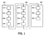
図面を参照すると、図1は、LV鼓動の視覚化をなす本発明による技術によりなされるステップのフローチャートを示している。患者のLVは、心臓周期のED(拡張末期)フェーズ(ブロック110)を確認するため、超音波画像形成及び/又はECGのような従来の監視技術を用いて初期の段階でモニタされる(ブロック100)。 Referring to the drawings, FIG. 1 shows a flowchart of the steps performed by the technique according to the invention for visualizing an LV beat. The patient's LV is monitored at an early stage using conventional monitoring techniques such as ultrasound imaging and / or ECG to confirm the ED (End Diastolic) phase (Block 110) of the cardiac cycle (Block 100).
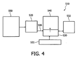
模範的技術においては、3D超音波心臓検査システムを用いることができる。このシステムは、ディジタル画像列を取り込むための手段を有し、その取り込んだ3Dボリュームデータを処理するためのディジタル処理システムに関連づけられる。図4に示される検査システム550は、表示及び/又は記憶手段530,540に画像データを供給するために少なくとも1つの出力506を有する処理システムに画像データを供給するための手段を有する。この表示及び記憶手段は、それぞれワークステーション510のスクリーン及びメモリとすることができる。ワークステーション510はまた、キーボード531及びマウス532を有してもよい。
In an exemplary technique, a 3D ultrasound cardiography system can be used. The system has means for capturing digital image sequences and is associated with a digital processing system for processing the captured 3D volume data. The
画像処理システム520は、ワークステーション510の適切にプログラムされたコンピュータとしてもよいし、或いは本発明による方法ステップの機能を果たすように構成されたフィルタ、論理演算子、メモリなどの回路手段を有する特定用途向けプロセッサとしてもよい。処理システム520は、当該方法ステップを行うために処理システム520の計算手段により実行されるべきプログラム命令を有するコンピュータプログラム製品を用いてもよい。
The
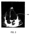
3Dボリューム取得の後、当該心臓周期のEDフェーズにおけるLVに対応する3D画像データは、図2において分かるようにLVの計算された境界400を生成するように処理される。
After 3D volume acquisition, the 3D image data corresponding to the LV in the ED phase of the cardiac cycle is processed to produce a calculated
そして、コンピュータアルゴリズムは、コンピュータ生成の境界内の一連のポイントを選択するようにユーザを促し(ブロック120)、当該境界内の画像の領域を完全にカバーする3Dの網目を生成するために情報を用い(ブロック130)、LVの表面を規定する。(このセグメンテーション技術は、「有限要素法」に関連しており、これは画像データの解析に用いられる幾つかの標準的な数学的技術のうちの1つである)。この態様において、基準網目は、心臓周期におけるLVのEDフェーズに対して得られる。必要に応じて、コンピュータにより生成された網目をこの段階(ブロック140)で変更することができる。 The computer algorithm then prompts the user to select a series of points within the computer-generated boundary (block 120) and uses the information to generate a 3D mesh that completely covers the area of the image within the boundary. Use (block 130) to define the surface of the LV. (This segmentation technique is related to the “finite element method”, which is one of several standard mathematical techniques used to analyze image data). In this embodiment, a reference mesh is obtained for the ED phase of the LV in the cardiac cycle. If necessary, the computer-generated mesh can be changed at this stage (block 140).
LVのES(収縮末期)(ブロック200)フェーズは、その後、LVの境界が再度決められる形で同様に確認され(ブロック210)、対応の網目が一連のポイントを選択(ステップ220)するユーザによって発生される(ステップ230)。ここでも、この網目は、必要に応じて変更可能である(ブロック240)。 The ES (end systole) (block 200) phase of the LV is then similarly confirmed (block 210) in such a way that the LV boundary is re-determined, and the corresponding mesh selects a series of points (step 220) by the user. Is generated (step 230). Again, this mesh can be changed as needed (block 240).
心臓周期のED(ブロック100)及びES(ブロック200)フェーズの判定の後、LVの境界は、EDからESまで(ブロック310)の選択された時間間隔(ブロック300)で心臓周期内の3D画像の列から判定され、対応の網目が自動的に発生され(ブロック320)、必要に応じて変更することができる(ブロック330)。 After determination of the ED (Block 100) and ES (Block 200) phases of the cardiac cycle, the boundary of the LV is a 3D image within the cardiac cycle at a selected time interval (Block 300) from ED to ES (Block 310). The corresponding mesh is automatically generated (block 320) and can be changed as needed (block 330).
本発明においては、その後システムが、予め選択された構成(LVのEDフェーズ)における構造体の基準画像を有する画像表示に、時間に対して変化するのにつれて当該構造体の変化画像を重ねるようにレンダリングする。 In the present invention, the system then superimposes a change image of the structure over time on an image display having a reference image of the structure in a preselected configuration (LV ED phase). Render.
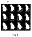
したがって、連続的に取り込んだ網目フレームを再生することによって、3DのLV境界は、生の鼓動する対象として表示されることが可能であり、ED基準網目内に表示されるときには、心臓周期において現フレームと基準フレーム500との間に明確な乖離を確認することができる(図3)。さらに、網目の重ね合わせは、全体の動きの強調も兼ね、当該LVは、例えば1呼吸の間において担当することができる。このような視覚画像は、時間につき変化するにつれLVの表面の動きの収集される評価を提供し、これにより、1つのフレーム時間しか示さない従来技術とは対照的に、その視覚画像は、心臓周期全体にわたりLV境界の変化を示すことになる。 Thus, by replaying continuously captured mesh frames, a 3D LV boundary can be displayed as a live beating target, and when displayed within an ED reference mesh, it is present in the cardiac cycle. A clear divergence can be confirmed between the frame and the reference frame 500 (FIG. 3). Furthermore, the mesh overlay also serves as an enhancement of the overall movement, and the LV can be in charge during, for example, one breath. Such a visual image provides a collected assessment of LV surface motion as it changes over time, so that, in contrast to the prior art, which shows only one frame time, the visual image It will show a change in the LV boundary over the entire period.
なお、この画像の視覚化はここでは網目の形態で提示したが、本発明の範囲から外れない他の視覚的処置も可能であることを理解されたい。したがって、基準網目及び時間的に変動する網目が画像を簡単に表すことが分かる。このデータは、同様にLVの表面の他の表現を生成するように操作することもできる。 It should be understood that although the visualization of this image is presented here in the form of a mesh, other visual procedures are possible that do not depart from the scope of the present invention. Therefore, it can be seen that the reference mesh and the time-varying mesh simply represent the image. This data can be manipulated to generate other representations of the surface of the LV as well.
また、主として超音波画像形成技術を説明したが、本発明は、例えば磁気共鳴映像法(MRI)又はコンピュータ断層撮影(CT)などの他の技術を用いて得られる画像データを操作し表示するために用いることができる。 Also, although ultrasonic imaging techniques have been primarily described, the present invention is for manipulating and displaying image data obtained using other techniques such as magnetic resonance imaging (MRI) or computed tomography (CT). Can be used.
さらに、上述した実施例は、本発明を限定するのではなく例証するものであり、当業者であれば、添付の請求項により規定されるような本発明の範囲を逸脱することなく数多くの代替えの実施例を構成することができる。請求項において、括弧内に付された参照符号は、当該請求項を限定するものと解釈してはならない。「有する」及び「有し」などの文言は、いずれの請求項又は明細書全体において挙げられた他の要素又はステップの存在を排除するものではない。要素の単数表現は、そのような要素の複数の存在を排除するものではないし、逆に複数表現も単数の存在を排除するものでもない。本発明は、複数の個別の要素を有するハードウェアにより、また適切にプログラムされたコンピュータにより実施可能である。複数の手段を列挙する装置の請求項においては、これら手段の幾つかが同一アイテムのハードウェアにより具現化されてもよい。或る方策が相互に異なる従属請求項において挙げられている過ぎない点は、これら方策の組み合わせを活用することができないことを示すものではない。 Furthermore, the above-described embodiments illustrate rather than limit the invention, and those skilled in the art will recognize numerous alternatives without departing from the scope of the invention as defined by the appended claims. This embodiment can be configured. In the claims, any reference signs placed between parentheses shall not be construed as limiting the claim. Words such as “having” and “having” do not exclude the presence of other elements or steps recited in any claim or specification. The singular representation of an element does not exclude the presence of a plurality of such elements, and conversely, the plural representation does not exclude the presence of a singular. The present invention can be implemented by hardware having a plurality of individual elements and by a suitably programmed computer. In the device claim enumerating several means, several of these means may be embodied by one and the same item of hardware. The mere fact that certain measures are recited in mutually different dependent claims does not indicate that a combination of these measures cannot be utilized.
Claims (13)
Applications Claiming Priority (2)
| Application Number | Priority Date | Filing Date | Title |
|---|---|---|---|
| US60580804P | 2004-08-31 | 2004-08-31 | |
| PCT/IB2005/052803 WO2006025005A2 (en) | 2004-08-31 | 2005-08-26 | Imaging system for displaying a structure of temporally changing configuration |
Publications (1)
| Publication Number | Publication Date |
|---|---|
| JP2008511368A true JP2008511368A (en) | 2008-04-17 |
Family
ID=35677551
Family Applications (1)
| Application Number | Title | Priority Date | Filing Date |
|---|---|---|---|
| JP2007529103A Pending JP2008511368A (en) | 2004-08-31 | 2005-08-26 | Image forming system for displaying structure of structure with time change |
Country Status (3)
| Country | Link |
|---|---|
| EP (1) | EP1794719A2 (en) |
| JP (1) | JP2008511368A (en) |
| WO (1) | WO2006025005A2 (en) |
Cited By (2)
| Publication number | Priority date | Publication date | Assignee | Title |
|---|---|---|---|---|
| JP2012515010A (en) * | 2009-01-13 | 2012-07-05 | コーニンクレッカ フィリップス エレクトロニクス エヌ ヴィ | Image-based clinical trial evaluation |
| WO2013150911A1 (en) * | 2012-04-04 | 2013-10-10 | コニカミノルタ株式会社 | Image generation device and program |
Families Citing this family (1)
| Publication number | Priority date | Publication date | Assignee | Title |
|---|---|---|---|---|
| DE102006020864A1 (en) * | 2006-05-04 | 2007-11-08 | Siemens Ag | Method for determining and displaying at least one information about a target volume |
Citations (4)
| Publication number | Priority date | Publication date | Assignee | Title |
|---|---|---|---|---|
| JPH09313485A (en) * | 1996-06-04 | 1997-12-09 | Toshiba Corp | Ultrasonic Doppler diagnostic apparatus and method of ultrasonic Doppler diagnostic |
| JPH11290325A (en) * | 1998-04-09 | 1999-10-26 | Hitachi Medical Corp | Ultrasonic diagnostic system |
| JP2002085409A (en) * | 2000-09-18 | 2002-03-26 | Toshiba Corp | Ultrasound diagnostic equipment |
| JP2004195028A (en) * | 2002-12-19 | 2004-07-15 | Aloka Co Ltd | Ultrasonic diagnostic apparatus |
Family Cites Families (2)
| Publication number | Priority date | Publication date | Assignee | Title |
|---|---|---|---|---|
| FR2545349B1 (en) * | 1983-05-04 | 1986-09-26 | Duret Francois | PROCESS FOR INPUT OF THE FORM OF HUMAN ORGANS OR PATHOLOGICAL ABNORMALITIES AND DEVICE FOR IMPLEMENTING SAME |
| EP1527422B1 (en) | 2002-06-28 | 2019-05-22 | Koninklijke Philips N.V. | Image processing method for displaying information relating to wall motions of a deformable 3-d object |
-
2005
- 2005-08-26 JP JP2007529103A patent/JP2008511368A/en active Pending
- 2005-08-26 WO PCT/IB2005/052803 patent/WO2006025005A2/en not_active Ceased
- 2005-08-26 EP EP05776677A patent/EP1794719A2/en not_active Withdrawn
Patent Citations (4)
| Publication number | Priority date | Publication date | Assignee | Title |
|---|---|---|---|---|
| JPH09313485A (en) * | 1996-06-04 | 1997-12-09 | Toshiba Corp | Ultrasonic Doppler diagnostic apparatus and method of ultrasonic Doppler diagnostic |
| JPH11290325A (en) * | 1998-04-09 | 1999-10-26 | Hitachi Medical Corp | Ultrasonic diagnostic system |
| JP2002085409A (en) * | 2000-09-18 | 2002-03-26 | Toshiba Corp | Ultrasound diagnostic equipment |
| JP2004195028A (en) * | 2002-12-19 | 2004-07-15 | Aloka Co Ltd | Ultrasonic diagnostic apparatus |
Cited By (4)
| Publication number | Priority date | Publication date | Assignee | Title |
|---|---|---|---|---|
| JP2012515010A (en) * | 2009-01-13 | 2012-07-05 | コーニンクレッカ フィリップス エレクトロニクス エヌ ヴィ | Image-based clinical trial evaluation |
| WO2013150911A1 (en) * | 2012-04-04 | 2013-10-10 | コニカミノルタ株式会社 | Image generation device and program |
| JP5408400B1 (en) * | 2012-04-04 | 2014-02-05 | コニカミノルタ株式会社 | Image generating apparatus and program |
| US9990735B2 (en) | 2012-04-04 | 2018-06-05 | Konica Minolta, Inc. | Image generation device that acquires images based on a periodic variation of an anatomical structure |
Also Published As
| Publication number | Publication date |
|---|---|
| WO2006025005A2 (en) | 2006-03-09 |
| WO2006025005A3 (en) | 2006-05-11 |
| EP1794719A2 (en) | 2007-06-13 |
Similar Documents
| Publication | Publication Date | Title |
|---|---|---|
| JP5322548B2 (en) | X-ray CT apparatus, medical image processing apparatus, and medical image processing program | |
| JP6318739B2 (en) | Image processing apparatus and program | |
| EP2545528B1 (en) | Motion visualisation in angiographic images | |
| WO2014192504A1 (en) | Image processing device and program | |
| JP5566370B2 (en) | Medical image processing apparatus and method | |
| US9367904B2 (en) | Spatial-temporal warping of different pre-captured medical images | |
| JP2006524087A (en) | Equipment for angiographic radiography | |
| JP2007167656A (en) | Method of analyzing motion of object and tomography apparatus | |
| JP5029702B2 (en) | Image generating apparatus, image generating method, and program | |
| CN101355904A (en) | Reconstruction unit for reconstructing a precise reproduction of at least a portion of an object | |
| CN102223843B (en) | Visualization of coronary artery tree | |
| JP2011036300A (en) | Image processor | |
| JP2010154982A (en) | X-ray computer tomographic imaging apparatus and image processor | |
| JP5380231B2 (en) | Medical image display apparatus and method, and program | |
| JP4532492B2 (en) | Spatial-temporal modeling system using guide points | |
| JP2019180545A (en) | Prediction device, prediction method, and prediction program | |
| JP2011067279A (en) | Medical image processor and medical image processing program | |
| JP2010057795A (en) | Image display device and program | |
| CN101479769A (en) | Model-based determination of the contraction status of a periodically contracting object | |
| JP2008511368A (en) | Image forming system for displaying structure of structure with time change | |
| JP5408493B2 (en) | Medical image processing apparatus and medical image processing program | |
| JP2013040829A (en) | Volume data processor and method | |
| JP2005136594A (en) | Image processing apparatus and control method thereof | |
| JPWO2010079689A1 (en) | Image display device, program, and image display method | |
| JP2010005109A (en) | Image forming device, program, and image forming method |
Legal Events
| Date | Code | Title | Description |
|---|---|---|---|
| A621 | Written request for application examination |
Free format text: JAPANESE INTERMEDIATE CODE: A621 Effective date: 20080826 |
|
| A131 | Notification of reasons for refusal |
Free format text: JAPANESE INTERMEDIATE CODE: A131 Effective date: 20110125 |
|
| A02 | Decision of refusal |
Free format text: JAPANESE INTERMEDIATE CODE: A02 Effective date: 20111004 |