JP2008508539A - Sonar imaging system for ship - Google Patents
Sonar imaging system for ship Download PDFInfo
- Publication number
- JP2008508539A JP2008508539A JP2007524919A JP2007524919A JP2008508539A JP 2008508539 A JP2008508539 A JP 2008508539A JP 2007524919 A JP2007524919 A JP 2007524919A JP 2007524919 A JP2007524919 A JP 2007524919A JP 2008508539 A JP2008508539 A JP 2008508539A
- Authority
- JP
- Japan
- Prior art keywords
- scan
- sonar image
- sonar
- acoustic element
- housing
- Prior art date
- Legal status (The legal status is an assumption and is not a legal conclusion. Google has not performed a legal analysis and makes no representation as to the accuracy of the status listed.)
- Pending
Links
Images


Classifications
-
- G—PHYSICS
- G01—MEASURING; TESTING
- G01S—RADIO DIRECTION-FINDING; RADIO NAVIGATION; DETERMINING DISTANCE OR VELOCITY BY USE OF RADIO WAVES; LOCATING OR PRESENCE-DETECTING BY USE OF THE REFLECTION OR RERADIATION OF RADIO WAVES; ANALOGOUS ARRANGEMENTS USING OTHER WAVES
- G01S15/00—Systems using the reflection or reradiation of acoustic waves, e.g. sonar systems
- G01S15/02—Systems using the reflection or reradiation of acoustic waves, e.g. sonar systems using reflection of acoustic waves
- G01S15/06—Systems determining the position data of a target
- G01S15/08—Systems for measuring distance only
- G01S15/10—Systems for measuring distance only using transmission of interrupted, pulse-modulated waves
- G01S15/102—Systems for measuring distance only using transmission of interrupted, pulse-modulated waves using transmission of pulses having some particular characteristics
- G01S15/107—Systems for measuring distance only using transmission of interrupted, pulse-modulated waves using transmission of pulses having some particular characteristics using frequency agility of carrier wave
-
- G—PHYSICS
- G01—MEASURING; TESTING
- G01S—RADIO DIRECTION-FINDING; RADIO NAVIGATION; DETERMINING DISTANCE OR VELOCITY BY USE OF RADIO WAVES; LOCATING OR PRESENCE-DETECTING BY USE OF THE REFLECTION OR RERADIATION OF RADIO WAVES; ANALOGOUS ARRANGEMENTS USING OTHER WAVES
- G01S7/00—Details of systems according to groups G01S13/00, G01S15/00, G01S17/00
- G01S7/52—Details of systems according to groups G01S13/00, G01S15/00, G01S17/00 of systems according to group G01S15/00
- G01S7/521—Constructional features
-
- G—PHYSICS
- G01—MEASURING; TESTING
- G01S—RADIO DIRECTION-FINDING; RADIO NAVIGATION; DETERMINING DISTANCE OR VELOCITY BY USE OF RADIO WAVES; LOCATING OR PRESENCE-DETECTING BY USE OF THE REFLECTION OR RERADIATION OF RADIO WAVES; ANALOGOUS ARRANGEMENTS USING OTHER WAVES
- G01S15/00—Systems using the reflection or reradiation of acoustic waves, e.g. sonar systems
- G01S15/88—Sonar systems specially adapted for specific applications
- G01S15/89—Sonar systems specially adapted for specific applications for mapping or imaging
- G01S15/8902—Side-looking sonar
-
- G—PHYSICS
- G01—MEASURING; TESTING
- G01S—RADIO DIRECTION-FINDING; RADIO NAVIGATION; DETERMINING DISTANCE OR VELOCITY BY USE OF RADIO WAVES; LOCATING OR PRESENCE-DETECTING BY USE OF THE REFLECTION OR RERADIATION OF RADIO WAVES; ANALOGOUS ARRANGEMENTS USING OTHER WAVES
- G01S15/00—Systems using the reflection or reradiation of acoustic waves, e.g. sonar systems
- G01S15/88—Sonar systems specially adapted for specific applications
- G01S15/96—Sonar systems specially adapted for specific applications for locating fish
Abstract
船舶のためのソナー画像システムが開示される。ソナー画像システムは、船舶に連結された送受波器を備え、送受波器は、少なくとも1つのサイドスキャニング素子と、少なくとも1つのボトムスキャニング素子と、を備える。また、ソナー画像システムは、送受波器に連結され、ソナー画像を表示するよう構成された電子制御ヘッドユニットを備える。下方音響素子は円形であってもよく、サイドスキャン音響素子は矩形であってもよい。船舶のモータにおけるスパークプラグまたは他の動作によって発生するノイズを除去するためのソフトウェアフィルタが設けられても良い。 A sonar imaging system for a ship is disclosed. The sonar imaging system comprises a transducer coupled to a ship, the transducer comprising at least one side scanning element and at least one bottom scanning element. The sonar imaging system also includes an electronically controlled head unit coupled to the transducer and configured to display the sonar image. The lower acoustic element may be circular, and the side scan acoustic element may be rectangular. A software filter may be provided to remove noise generated by spark plugs or other actions in the motor of the ship.
Description
[関連特許出願のクロスリファレンス]
本特許出願は、2004年8月2日に出願された米国仮特許出願第60/598,326号並びに2005年8月2日に出願された通常の米国特許出願第 号の利益を主張し、その教唆および開示を全体として参照により本明細書に組み込む。
[発明の分野]
本発明は、一般的に、魚群探知機、ソナー測深機などの、スポーツフィッシング用で使用されるソナー画像システムに関する。さらに具体的には、本発明は、船舶の真下ではなく船舶の側方両側の水中環境を画像化するサイドスキャンソナー画像システムに関する。
[発明の背景]
従来より、音波を発信するソナーデバイスは、魚、構造物、および障害物などの水中物、および水底に関する情報を得るために使われてきた。音波は船の底面に取り付けられた送受波器から水中に進む。音波はソナーデバイスから拡散パターンで発信される。音波が水中物に当たると、反射エコーを生じる。送受波器は反射エコーを受信して、ソナーデバイスが受信したエコーを解析する。魚や他の水中物の位置を特定するために、ディスプレイデバイスが受信したエコーの描画を表示する。
[Cross-reference of related patent applications]
This patent application claims the benefit of U.S. Provisional Patent Application No. 60 / 598,326 filed on August 2, 2004 and the conventional U.S. Patent Application No. filed on August 2, 2005, The teachings and disclosures are incorporated herein by reference in their entirety.
[Field of the Invention]
The present invention relates generally to sonar imaging systems used for sports fishing, such as fish finders, sonar sounders, and the like. More specifically, the present invention relates to a side-scan sonar imaging system that images an underwater environment on both sides of a ship, not directly under the ship.
[Background of the invention]
Conventionally, sonar devices that transmit sound waves have been used to obtain information about underwater objects such as fish, structures, and obstacles, and the bottom of the water. Sound waves travel into the water from a transducer attached to the bottom of the ship. Sound waves are emitted from the sonar device in a diffuse pattern. When sound waves hit underwater, a reflected echo is generated. The transducer receives the reflected echo and analyzes the echo received by the sonar device. Displays echo plots received by the display device to locate fish and other underwater objects.
周知のサイドスキャンソナーデバイスにおいては、船舶によって曳航される船(例えば、「曳航体」)に送受波器が設置される。曳航体は長いケーブルでソナーディスプレイに連結される。ケーブルの長さは水深および他の条件によって変わる。典型的なアプリケーションの場合、ケーブルの長さは50フィート以上である。さらに、ケーブルが数百フィートあるいは数千フィートもの長さになることも珍しいことではない。当業者は理解できるであろうが、漁師または娯楽上の使用者がサイドスキャン画像を取得することを望んでも、このような構成が障害になるであろう。例えば、船舶を様々な方向に操作または旋回することは難しく、またソナーケーブルが釣り用具または他のレジャー用品に絡まる。当該周知の曳航体送受波器は水の底から一定の距離に維持される。この距離は所望もしくは最適な分解能と視界を得ることを目的としたものである。船舶が移動するとともに水深が変化することに応じて送受波器から水底までの距離が変わることから、一定の距離に維持しなければならないことが、周知の送受波器をサイドスキャン用に改造すること(または周知のサイドスキャン送受波器を船舶に搭載すること)を不可能にしているとはいえないまでも、妨げている。 In a known side scan sonar device, a transducer is installed on a ship towed by a ship (eg, “towed body”). The towing body is connected to the sonar display with a long cable. The cable length varies depending on the water depth and other conditions. For typical applications, the cable length is 50 feet or more. In addition, it is not uncommon for cables to be hundreds or thousands of feet long. As one skilled in the art will appreciate, such a configuration would be an obstacle if a fisherman or recreational user wishes to obtain a side-scan image. For example, it is difficult to maneuver or turn the ship in various directions, and sonar cables get tangled in fishing gear or other leisure equipment. The known towed transducer is maintained at a certain distance from the bottom of the water. This distance is intended to obtain the desired or optimal resolution and field of view. Since the distance from the transmitter / receiver to the bottom of the water changes as the ship moves and the water depth changes, it is necessary to maintain a certain distance. (Or mounting a well-known side-scan transducer on a ship), if not impossible.
従って、フレキシブルケーブルに連結して船舶の後方で曳航されるのではなく、船舶に連結されたソナー画像システムを提供することが好ましいであろう。また、モータ(例えば、トローリングモータなど)、船舶のトランソム、または船舶の船体に搭載可能なソナー画像システムを提供することが好ましいであろう。また、水底の深さの変化に応じて最適な性能が得られるよう、複数の共振周波数で作動可能なソナー画像システムを提供することが好ましいであろう。一または複数の上記の好ましい特徴もしくは他の有利な特徴を備える船舶搭載用のソナー画像システムを提供することが望ましいであろう。
[発明の概要]
上記事項に鑑みて、本発明の目的は、漁船などの船舶に接続できる、新規で改良されたソナー画像システムを提供することである。別の目的は、船舶の側方両側の水中環境の画像を提供する新規で改良されたソナー画像システムを提供することである。本発明のさらに別の目的は、船舶の下方の水中環境の画像を追加的に提供する新規で改良されたソナー画像システムを提供することである。
Accordingly, it would be desirable to provide a sonar imaging system that is connected to a ship rather than connected to a flexible cable and towed behind the ship. It would also be desirable to provide a sonar imaging system that can be mounted on a motor (eg, a trolling motor, etc.), a vessel transom, or a vessel hull. It would also be desirable to provide a sonar imaging system that can operate at multiple resonance frequencies so that optimum performance is obtained in response to changes in the depth of the bottom of the water. It would be desirable to provide a marine sonar imaging system with one or more of the above preferred features or other advantageous features.
[Summary of Invention]
In view of the above, it is an object of the present invention to provide a new and improved sonar imaging system that can be connected to a vessel such as a fishing boat. Another object is to provide a new and improved sonar imaging system that provides images of the underwater environment on both sides of a ship. Yet another object of the present invention is to provide a new and improved sonar imaging system that additionally provides an image of the underwater environment below the ship.
本発明のシステムは、従来の曳航体式サイドスキャンソナーシステムより優れたいくつかの利点を実現する。送受波器曳航体を水中に入れるための装備の必要がなく、ケーブルの取り扱い上の面倒や絡みがなく、曳航体を正確な深度に維持して水底に衝突しないようにするために精密な速度制御の必要がなく、ボートを旋回したいときに曳航体が水底に当たらないように面倒な大回りをする必要がなく、釣りをしているときにラインやケーブルが絡む心配をしなくてもよいため、より便利である。本発明のシステムは後退中の船舶において画像化を行うためにも使用できる。 The system of the present invention provides several advantages over conventional towed side scan sonar systems. There is no need for equipment to put the towed body underwater, there is no hassle or entanglement in handling the cable, and the precise speed to keep the towed body at the correct depth and not hit the bottom of the water There is no need for control, and when you want to turn the boat, you don't have to make troublesome turns so that the towing body does not hit the bottom of the water, and you don't have to worry about tangling lines and cables when fishing. Is more convenient. The system of the present invention can also be used for imaging on a retreating vessel.
また、本発明のシステムは、従来のサイドスキャンソナーシステムよりも安全である。曳航体が障害物に引っかかったり、または送受波器を紛失する可能性はなくなる。釣りは、ほとんどの場合、水底の隆起、断崖、および水中構造物付近で行われる。ほとんどの天然湖および特に人工湖には岩や切り株、立木があり、これらは曳航体に引っかかって、装置を損傷させたり、または紛失させたりする可能性がある。 Also, the system of the present invention is safer than conventional side scan sonar systems. There is no possibility of the towed body getting caught in an obstacle or losing the transducer. Fishing is most often done near the bottom ridges, cliffs and underwater structures. Most natural lakes, and especially artificial lakes, have rocks, stumps, and trees that can get caught in the towed body and damage or lose equipment.
加えて、本発明のシステムはより広い有効受信範囲を提供する。本発明の船舶に搭載の送受波器は船の旋回半径を制限せず、岸および構造物近傍を画像化することを可能にする。このため、より速くて、より完全な画像化が可能となる。本システムはまたより正確な標的の位置割り出しも可能にする。送受波器を船舶に搭載することで、精密な標的の位置割り出しを可能にする。曳航式サイドスキャンシステムでは、乗組員はケーブルをどれくらい出して、曳航体がどれくらいの深さに配置されたかを考慮して、標的がボートのどれくらい後方にあるかを判定しなければならない。本発明の船舶搭載システムでは、これが検討要素とはならない。さらにより正確な画像を提供するために、本発明のシステムはサイド画像送受波器とGPSアンテナとのXY座標距離を計算するために必要なオフセットを提供する。また、本発明のシステムは、いくつかの場合においては、いくつかの標的に対して、より良い側面を持つ。何故なら、水面からの視点の方が、水底から固定距離に配置される曳航式サイドスキャンソナーよりも、隆起の上方および穴の内部に至るまでより良く「見える」ことになるためである。また、本発明のシステムは、カヌー、カヤックその他のパーソナル・ウォータークラフトなどの、より小型の船舶にも搭載できる。 In addition, the system of the present invention provides a wider effective coverage. The transducer mounted on the ship of the present invention does not limit the turning radius of the ship, and makes it possible to image the shore and the vicinity of the structure. This allows faster and more complete imaging. The system also allows for more accurate target location. By mounting the transducer on the ship, it is possible to precisely determine the position of the target. In a towed side scan system, the crew must determine how far the target is behind the boat, taking into account how much of the cable is pulled out and how deep the towed body is located. In the shipboard system of the present invention, this is not a consideration factor. In order to provide an even more accurate image, the system of the present invention provides the necessary offset to calculate the XY coordinate distance between the side image transducer and the GPS antenna. The system of the invention also has better aspects for some targets in some cases. This is because the point of view from the water surface is better “visible” to the top of the ridge and into the interior of the hole than the towed side scan sonar placed at a fixed distance from the bottom of the water. The system of the present invention can also be installed in smaller ships such as canoes, kayaks and other personal watercraft.
本発明の好適な一実施例においては、本システムは船舶に送受波器を搭載する手法を補正する特徴を含む。水底から一定の距離の箇所でデータ収集を行い(どの水深でも同じアスペクト角)、曳航体の動きが荒海では船舶の動きとは切り離される曳航体を使用する場合とは異なり、本発明のシステムはこれらの差を補償する。本発明の好適な一実施例においては、サイド画像素子の下方向に傾けられた角度は約20度から約30度に上がる。これにより、より広い方向においてより良い有効受信範囲が提供される。また好適な一実施例においては、サイド素子は、2種類の周波数になるように構成される。これにより、有効受信範囲と分解能との間のトレードオフが提供される。また、好適な一実施例においては、送受波器の素子シールドとソフトウェアフィルタが設けられる。これにより、例えば、スパークプラグや電気システムのEMI(ソレノイド、VHFラジオ、電気モータなど)などによる船舶のノイズ源が排除される。本発明の好適な一実施例においては、本システムは、浮遊油槽セルフレベリングを利用した、受動的ヨーイング、送受波器傾斜の最小化または補償機構を有する。別の実施例においては、本システムは、傾斜センサおよびモータを介しての、能動的ヨーイング、送受波器傾斜の最小化または補償機構を有する。 In a preferred embodiment of the present invention, the system includes features that correct the technique of mounting a transducer on a ship. Unlike the case of using a towed vehicle that collects data at a certain distance from the bottom of the water (same aspect angle at any depth), and the towed vehicle is separated from the ship in the rough sea, the system of the present invention Compensate for these differences. In one preferred embodiment of the present invention, the downwardly tilted angle of the side image element increases from about 20 degrees to about 30 degrees. This provides a better effective reception range in a wider direction. In a preferred embodiment, the side element is configured to have two types of frequencies. This provides a trade-off between effective coverage and resolution. In a preferred embodiment, a transducer element shield and a software filter are provided. Thereby, for example, a noise source of a ship due to a spark plug or EMI (solenoid, VHF radio, electric motor, etc.) of the electric system is eliminated. In one preferred embodiment of the present invention, the system includes passive yawing, transducer tilt minimization or compensation mechanisms utilizing floating oil tank self-leveling. In another embodiment, the system has an active yaw, transducer tilt minimization or compensation mechanism via a tilt sensor and motor.
本発明の実施例によって提供される従来のサイドスキャンよりも優れた追加の特徴は、サイドビームによる魚の探知とアラームとを含む。典型的なサイドスキャンシステムは魚を不要なノイズとみなす。画像を記憶し、すでに記憶した画像を見直し、不要な画像を消去するとともに、画像をコンピュータにダウンロードする能力をもつデジタルカメラと同様のスクリーンキャプチャと再生機能も本発明の実施例において提供される。典型的なデータ記録の場合と異なり、ユーザーがスクリーン上の画像を見たときに、ユーザーは単にキャプチャボタンを押せばよい。ユーザーが標的を見る前から記録を開始しなければならないことはない。好適な実施例は、ユーザーが一度に右側もしくは左側だけを見て、しかも、カーソルまたはタッチスクリーンのいずれかを使用してあるエリアにズームインできるズーム機能も提供する。さらに、色、コントラスト、輝度、自動補正、輪郭検出等に関して、ユニットまたは後処理のいずれかにより標準的な画像補正ソフトウェア(アルゴリズム)を使うことも可能になる。 Additional features over conventional side scans provided by embodiments of the present invention include side beam fish detection and alarms. A typical sidescan system considers fish as unwanted noise. Screen capture and playback functions similar to those of a digital camera with the ability to store images, review previously stored images, erase unwanted images, and download images to a computer are also provided in embodiments of the present invention. Unlike typical data recording, when a user views an image on the screen, the user simply presses the capture button. Recording does not have to start before the user sees the target. The preferred embodiment also provides a zoom function that allows the user to view only the right or left side at a time and zoom in on an area using either a cursor or a touch screen. In addition, standard image correction software (algorithms) can be used for either color, contrast, brightness, automatic correction, contour detection, etc., either by unit or post-processing.
本発明の好適な一実施例においては、サイド画像とともにダウンビームが提供される。これはより(側方両側および下方の)完全なボート周辺情報が提供される。これは1ビームに限定されない。一実施例においては、200kHz/50kHzの2種類のビームが利用される。別の実施例では、4種類のビームまたはさらに6種類のビームが利用されうる。好適な実施例においては、少なくとも1つの画面がダウンビームとサイド画像の両方を表示する。これにより、陰影情報の長さを、水中の標的のサイズに、よりよく関係付けることができる。また、これは標的の位置を素早く確認する手段にもなる。標的が側方にずれた後、ボートを標的の真上に動かして、正確な位置割り出しのためにダウンビームの範囲内に入れることができる。 In a preferred embodiment of the present invention, a down beam is provided along with a side image. This provides more complete boat perimeter information (on both sides and below). This is not limited to one beam. In one embodiment, two types of 200 kHz / 50 kHz beams are utilized. In other embodiments, four types of beams or even six types of beams may be utilized. In the preferred embodiment, at least one screen displays both the down beam and the side image. This makes it possible to better relate the length of the shadow information to the size of the target in the water. This also provides a means for quickly confirming the position of the target. After the target has shifted to the side, the boat can be moved directly above the target to be within range of the down beam for accurate position determination.
さらに別の好適な一実施例では、GPS画像もサイド画像とともに提供される。当該実施例では、カーソルモードにおいて、ユーザーが、スクリーン画像上でカーソルを対象標的の上に移動させて、構造物の位置に向かう航路位置を設定できる。GPSの履歴は、後方距離を判定するのに使用されても良い。また、ソナーは、側方距離を判定するのに使用されてもよい。GPS速度は、標的のより正確な前後寸法を提供するのに必要なスクリーンのスクロール速度を提供するために使用されてもよい。GPSまたは速度センサがない場合、速いスクロール速度と遅い船舶速度は、標的の長さを長くさせる。遅いスクロール速度と速い船舶速度は、標的の長さを短くさせる。ユニットにおいて、コンポジット・モザイク画像が、生成されるか、あるいは後で後処理されうるように、スクリーンキャプチャの角がマークされるようにしてもよい。好ましくは、サイド画像とナビゲーション情報との両方を示す1つの画面が提供される。これにより、航路がたどりやすくなるとともに、効果的な領域範囲が提供されやすくなる。 In yet another preferred embodiment, GPS images are also provided along with side images. In the embodiment, in the cursor mode, the user can set the route position toward the position of the structure by moving the cursor on the target target on the screen image. The GPS history may be used to determine the rear distance. Sonar may also be used to determine lateral distance. The GPS speed may be used to provide the screen scroll speed necessary to provide a more accurate longitudinal dimension of the target. In the absence of GPS or speed sensors, fast scrolling speeds and slow ship speeds increase the length of the target. A slow scrolling speed and a fast ship speed will shorten the length of the target. In the unit, a corner of the screen capture may be marked so that a composite mosaic image can be generated or later processed. Preferably, one screen showing both the side image and the navigation information is provided. As a result, the route can be easily traced and an effective area range can be easily provided.
以上の目的に沿って、本発明の実施例は、船舶に連結された送受波器を有する船舶用ソナー画像システムを提供する。好ましくは、本システムは、少なくとも1つのサイドスキャニング素子と、少なくとも1つのボトムスキャニング素子と、ソナー画像を表示するように構成された送受波器に連結される電子制御ヘッドユニットとを有する。本発明の一実施例においては、ソナー画像システムは、円形の下方音響素子と矩形の音響素子とを有する。さらに、本発明は、船舶のモータにおけるスパークプラグまたは他の動作によって発生するノイズを除去するように構成されたソフトウェアフィルタに関する。 In accordance with the above object, an embodiment of the present invention provides a marine sonar image system having a transducer connected to a marine vessel. Preferably, the system includes at least one side scanning element, at least one bottom scanning element, and an electronically controlled head unit coupled to a transducer configured to display a sonar image. In one embodiment of the invention, the sonar imaging system has a circular lower acoustic element and a rectangular acoustic element. The present invention further relates to a software filter configured to remove noise generated by a spark plug or other operation in a marine motor.
発明の他の側面、目的、および利点は、添付の図面に照らして以下の詳細な説明を読めばより明らかになるであろう。
明細書に組み込まれ、その一部をなす添付の図面は、本発明のいくつかの側面を例示し、明細書における記述とともに、本発明の原理の説明に役立つ。
Other aspects, objects and advantages of the invention will become more apparent from the following detailed description when read in conjunction with the accompanying drawings.
The accompanying drawings, which are incorporated in and constitute a part of the specification, illustrate several aspects of the invention and, together with the description in the specification, serve to explain the principles of the invention.
以下では、所定の好適な実施例に関連付けて本発明につき説明するが、本発明をそれら実施例に制限する意図ではない。反対に、添付の請求項で定義される発明の精神および範囲に含まれるすべての代替例、変形例、並びに均等物を含むことが意図される。
[発明の詳細な説明]
ここで図面を参照すると、図1は水底16を有する水14の水面12に浮かぶ(船舶10として示される)船を図示している。ソナー画像システム18は、(例えば、船舶10の後方でフレキシブルケーブルによって曳航されるのではなく)船舶10に搭載または連結される。ソナー画像システム18は、船舶の下方および船舶の側方両側の水をスキャンするように構成されている(すなわち、ボート搭載サイドスキャンソナーシステムと言える)。ソナー画像システム18は船舶10に配置される電子制御ヘッドユニット22に連結されるトランスポンダまたは送受波器20を備える。ソナー画像システム18は、音波を発信し、ソナー反射波を受信して表示するという手法で、魚や他の水中物があるか水体14を繰返しスキャンする。前の発信から受信までの時間は判定対象の水深の関数である。
In the following, the present invention will be described with reference to certain preferred embodiments, but the present invention is not intended to be limited to these embodiments. On the contrary, the intent is to cover all alternatives, modifications and equivalents included within the spirit and scope of the invention as defined by the appended claims.
Detailed Description of the Invention
Referring now to the drawings, FIG. 1 illustrates a ship (shown as a ship 10) that floats on the
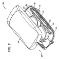
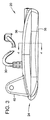
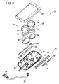
図2から図11に示されているように、送受波器20は、ハウジング24と、(サイドスキャン素子26と下方スキャン素子28として示される複数の音響素子の形式の)ソナーアレイと、上記ハウジングおよび音響素子を電子制御ヘッドユニット22に連結するケーブル30と、を含む。音響素子は、水14をスキャンするために、具体的には、魚および他の水中物の位置を特定し、水の水底16(図1参照)に関する特徴を検出するために、電子制御ヘッドユニット22によって操作される送信機および受信機で音波を送受信するように構成される。音波ビームまたはソナー波ビームは音響素子の構成に基づいて発信される。
As shown in FIGS. 2-11, the
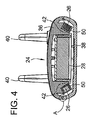
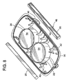
ハウジング24は上側ハウジング部36と下側ハウジング部38とを備える。上側ハウジング部36は、上側ハウジング部36の前部から延出した一対の取り付け部材40を有する。上側ハウジング部36と下側ハウジング部38とは、ともに、ハウジングアセンブリの構造的な支持を実現するとともに、音響素子の配置、位置決め、支持を実現するため、ハウジングの内部に向かって延出した突起を有する。一連の突起42は、サイドスキャン素子26を受ける受け台として構成されたV字形の凹部または切欠44を有する。凹部44は、特定の望ましい所定の音響ビーム性能を実現する位置および向き(方向)に、矩形のサイドスキャン素子26を支持するように構成(成形および配置)される。
The
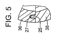
ハウジング24は様々な方法のいずれかによって船舶10に連結される。ハウジング24は、ハウジングの側方どちら側にも障害物がないように(すなわち、音響素子の作動の障害になる、またはその性能に悪影響を及ぼす障害物がないように)、船舶10に連結される。好適な一実施例においては、ハウジング24が船舶の下に約0.25インチ張り出すように、ハウジング24は、船舶の中心線に沿って船舶10に連結される。例示的な実施例においては、上側ハウジング36の取り付け部材40が、トローリングモータに連結された取り付けブラケット46に連結される。他の一実施例においては、取り付け部材40は、(例えば、船体における穴に通された支持シャフトを用いること等により)船舶10の船体部を介して取り付けられる。他の一実施例においては、取り付け部材は、船舶10のトランソムに連結されたブラケットに連結される。上記の代わりに、ハウジングは、船舶における種々の箇所のいずれかに連結されても良いし、水面下における種々の深さのいずれかに配置されるよう船舶に連結されても良い。上側ハウジング部36は、(例えば、スナップフィット嵌合、接着、超音波溶接、融着、熱溶接、ねじ・ボルト・リベット等の留め具などを用いた)様々な従来の方法のいずれかによって、下側ハウジング部38に連結されうる。図5に図示するように、ハウジング24の一実施例においては、取り付けチャネル27で受けられる取り付けリブ25を利用して、上側および下側ハウジング部36、37の両者を位置決めする。一実施例においては、リブ25が、例えば超音波溶接等の手法でチャネル27内に溶接される。
The
サイドスキャン素子26はハウジング24の側方両側に沿って配置され、ソナービームまたは音響ビーム47で送受波器20(および船舶10)の側方両側の水中をスキャンするように構成される。
The
サイドスキャン素子26の寸法は、所望のソナービームパルス47が提供されるように構成される。発信される音響ビームによって生み出される波面のサイズが反射エコーの分解能に影響を及ぼすため、この波面のサイズは、ソナーデバイスによって表示される水中物の画像の質にも影響を及ぼす。一般的に、広いビームは拡散された反射エコーを提供する。この拡散された反射エコーは船舶周囲の広い領域内での魚の有無を表示させるのに特に適している。魚に関して表示される信号は「フィッシュアーチ」または他の示標もしくはアイコンといわれる。他方で、より狭いビームはより詳細な反射エコーまたは水中物を表す信号を提供する。狭いビームは、小さい領域をカバーするにすぎないが、水中物に関する追加的な定義情報を提供する。それゆえ、より広いビームは船舶周囲の広い領域内での魚の群れの存在や他の水中物の存在に関する表示を提供させるのに役立つ。狭いビームは水中物または水底に関する詳細情報を提供させるのに役立つ。
The dimensions of the
ソナービームは、対応する音響素子の寸法が大きくなるほど狭くなる(それによってよりよい分解能を提供する)。また、ソナービームは、対応する音響素子の寸法が小さくなるほど広くなる(例えば、高さを低くすると鉛直方向の角度が比較的広くなり、長さを長くすると、水平方向の角度が比較的狭くなる)。例示的な一実施例では、水平方向のビーム幅が狭くなり、鉛直方向のビーム幅が広くなるように、サイドスキャン素子26は構成される。好適な一実施例においては、サイドスキャン素子は矩形である。特に好適な実施例における矩形のサイドスキャン素子26においては、その長さが約3インチから約7インチで、その幅が約0.125インチから約0.50インチである。特に好適な実施例における矩形のサイドスキャン素子26においては、その長さが約4.5インチで、その幅が約0.25インチである。図1に概略的に示されたこのような特に好適な実施例では、サイドスキャン素子26は、水平方向の角度49が約2度で、鉛直方向の角度51が約50度の音響ビーム47を発信する。
The sonar beam becomes narrower (thus providing better resolution) as the size of the corresponding acoustic element increases. In addition, the sonar beam becomes wider as the size of the corresponding acoustic element becomes smaller (for example, if the height is lowered, the angle in the vertical direction becomes relatively wide, and if the length is made longer, the angle in the horizontal direction becomes relatively narrow. ). In an exemplary embodiment, the
図1、図4、図6、および図7に示されているように、サイドスキャン素子26は、その露出面48が所定の方向に向かって所定の角度を持って向くように、ハウジング24内の突起42によって、支持される(例えば、捕捉される、把持される、保持される等)。例示的な一実施例においては、サイドスキャン素子26の露出面が、送受波器20と反対側の外側に向くとともに、水底の方向(例えば、船舶10および水面よりも下方向)に向くように、サイドスキャン素子26がハウジングによって支持される。好適な一実施例において、サイドスキャン素子26は、その共振周波数に応じて、下方向に約20度から約40度傾けられる。特に好適な一実施例では、サイドスキャン素子26は、約260kHzから約462kHzの共振周波数の場合においては、下方向に約30度傾いた方向に向けられる。他の実施例においては、サイドスキャン素子は、送受波器を使用しようとする水の水底のタイプ(例えば、湖、河川、海等)に応じて、また、(例えば、音響素子のサイズと寸法によって決まる)送受波器によるソナービームの構成に応じて、様々な傾きおよび方向となるよう取り付けられる。好ましくは、サイドスキャン素子26はエポキシ樹脂を使ってハウジング24に連結される。別の方法としては、サイドスキャン素子は、様々な接着剤、結合材料もしくは接合材料、またあるいは、結合技術もしくは接合技術のいずれかを用いてハウジングに連結される。
As shown in FIGS. 1, 4, 6, and 7, the
好適な一実施例においては、サイドスキャン素子26は、圧電性セラミックから作られる。特に好適な一実施例においては、サイドスキャン素子は、英国のモーガン・エレクトロ・セラミック社が市販しているジルコン酸チタン酸鉛(「PZT」)を用いて構成される。他の実施例においては、サイドスキャン素子は、電気エネルギーを機械エネルギーに変換できるとともに、機械エネルギーを電気エネルギーに変換できる様々な圧電性材料のうちのいずれかから作られる。
In a preferred embodiment, the
音響シールド50(例えば、シールディング、デカプラー、バリア、吸収体など)がサイドスキャン素子26の1面を除く他の全面を囲んでいる。これにより、所望のスキャン方向以外の方向に音響素子からソナーパルス送信されることや、所望のスキャン方向以外の方向からのソナー反射波を音響素子が受信することを防止する。音響シールド50は、コルク、発泡材、ポリマー、またはその他の低密度材料などの、ソナーエネルギーの不良伝道体である様々な材料のうちのいずれかから作ることができる。
An acoustic shield 50 (for example, shielding, decoupler, barrier, absorber, etc.) surrounds the entire surface other than one surface of the
下方スキャン素子28は、ハウジング24の底中央部に沿って配置される。下方スキャン素子28は、ソナーまたは音響ビーム53(図1参照)で送受波器20(および船舶10)の下方の水中をスキャンするように構成される。好適な一実施例において、下方スキャン素子28は、互いに連結された一対の送受波器素子を備える。他の実施例においては、下方スキャン素子は単一の素子または2個よりも多い個数の素子を備える。
The
下方スキャン素子28の寸法は、所望のソナービームパルスを提供できるように構成される。例示的な一実施例においては、下方スキャン素子28は、(例えば、所望または最適な分解能を得るため)比較的ビーム幅の狭いソナービームを提供するように構成される。好適な一実施例においては、下方スキャン素子28は、円筒形状を有している。特に好適な一実施例における円筒形の下方スキャン素子28では、その直径が約1インチから約2インチで、その高さが約0.2インチから約0.5インチである。特に好適な一実施例における円筒形の下方スキャン素子28では、その直径が約1.67インチで、その高さが約0.425インチである。図1に示すこのように特に好適な一実施例においては、下方スキャン素子28は、約20度の角度55で音響ビーム53を発信する。他の実施例においては、サイドスキャン素子と下方スキャン素子は、所望の性能、製造、およびコストに基づいて、様々な寸法、位置、および傾きを持ちうる。
The dimensions of the
下方スキャン素子28は、その露出面54が所定の方向に向かって所定の角度を持って向くように、ハウジング24内の突起52によって、支持される(例えば、捕捉される、把持される、保持される等)。例示的な一実施例においては、下方スキャン素子28の露出面が送受波器20から鉛直方向上の下側の水底に向くように、下方スキャン素子28がハウジングによって支持される。好ましくは、下方スキャン素子28はエポキシ樹脂を使ってハウジング24に連結される。別の方法として、下方スキャン素子は、様々な接着剤、結合材料もしくは接合材料、またあるいは、結合技術もしくは接合技術のいずれかを用いてハウジングに連結される。
The
好適な一実施例においては、下方スキャン素子28はセラミックから作られる。特に好適な一実施例においては、下方スキャン素子28は、英国のモーガン・エレクトロ・セラミック社が市販しているジルコン酸チタン酸鉛(「PZT」)を用いて構成される。他の実施例においては、下方スキャン素子は、電気エネルギーを機械エネルギーに変換できるとともに、機械エネルギーを電気エネルギーに変換できる様々な圧電性材料のうちのいずれかから作られる。
In one preferred embodiment, the
音響シールド56(例えば、シールディング、デカプラー、バリア、吸収体など)が下方スキャン素子28の1面を除く他の全面を囲んでいる。これにより、所望のスキャン方向以外の方向に音響素子からソナーパルス送信されることや、所望のスキャン方向以外の方向からのソナー反射波を音響素子が受信することを防止する。音響シールド56は、コルク、発泡材、ポリマー、またはその他の低密度材料などの、ソナーエネルギーの不良伝道体である様々な材料のうちのいずれかから作ることができる。
An acoustic shield 56 (eg, shielding, decoupler, barrier, absorber, etc.) surrounds the entire surface of the
水底反射により戻ってくる反射ソナー信号は水底16に関する詳細情報を有している。側方反射により戻ってくる反射ソナー信号は船舶10の側方両側における側方および水底16に関する詳細情報を有している。ソナー反射波データは、伝達され、あるいは、送られて、送受波器20において処理され、音波ビームの受信反射エコーを表す画像またはシンボルを表示させるために電子制御ヘッドユニット22に伝達され、あるいは、送られる。音響パルスの送信と反射エコーの受信とが1回の送受信サイクルであり、本明細書においては、このサイクルをT/Rサイクルという。音響パルスの波面は送受波器20から水14の水底16にまで進み、次いで、反射されることで送受波器に戻る。送受波器は、音波ビームの反射エコーを受信する。T/Rサイクルの期間は水深によって変わる。典型的には、送受信のT/Rサイクルは、水深が深い場合で1秒あたり2回から4回であり、水深が浅い場合には30分の1秒のように、より頻繁になる。
The reflected sonar signal returned by bottom reflection has detailed information about the bottom 16. The reflected sonar signal returned by side reflection has detailed information about the sides and the bottom 16 of the sides of the
好適な一実施例においては、送受波器20は電子機器をまったく備えていない。むしろ電子機器は電子制御ヘッドユニット22に配置される。その画像は、水底の地形、または、水底に沿って存在する物体(例えば、魚)、もしくは水中の物体(例えば、魚)などを含む。ディスプレイには情報対象となる事柄(例えば、水深、水温、船舶10の速度等)も表示されてもよい。
In one preferred embodiment, the
図12に示すように、電子制御ヘッドユニット22は電源に連結される。電子制御ヘッドユニット22は、ユーザー・インターフェース(58、60、および62)と、マイクロプロセッサ64と、コプロセッサ66と、第1サイドスキャン回路68と、第2サイドスキャン回路70と、ボトムスキャン回路72と、を備える。ユーザー・インターフェースは、ユーザーがディスプレイのメニューを通して水深範囲、感度、魚探アラームなどのパラメータを入力できるように構成される。ユーザー・インターフェースが、キーパッド58と、ブザー60と、ディスプレイ62と、を含むことが示されている。その代わりに、ユーザー・インターフェースは、スイッチ、または、押しボタンなどを備えてもよい。
As shown in FIG. 12, the electronic
マイクロプロセッサ64は、ユーザー・インターフェースに連結されている。マイクロプロセッサ64は、コプロセッサ66からのデータを処理する(例えば、表示される情報の制御、表示する情報のフォーマット、演算アルゴリズムの実行などを行う)ように構成される。マイクロプロセッサ64は、様々な入出力、制御、分析、および本明細書に記載されたその他の機能を実行するように構成された、マイクロコントローラ、特定用途向け集積回路(ASIC)、またはその他のデジタルおよびアナログ回路、もしくはデジタル回路あるいはアナログ回路であってもよい。一実施例においては、マイクロプロセッサ64は、本明細書に記載された機能を実行するソフトウェアを実装可能なメモリー(例えば、不揮発性メモリー)を有する。電子制御ヘッドユニット22のマイクロプロセッサ64は、プログラムされたアルゴリズム(例えば、ディファレンシャル・アンプリチュード・フィルタリング(エンジン・スパーク・ノイズの除去)など)、最善の画像を得るための時間変化利得の最適化、魚探アルゴリズム、分解能を高めるための発信時におけるアンチリンギングパルス、傾き角度範囲情報を補正するための下方向のビーム(ダウンビーム)の深さの使用、など)を実行する。好適な一実施例においては、ソフトウェア・フィルター・アルゴリズムが設けられる。これにより、船舶の作動において一般的な所定のノイズ(および、具体的には、スパークプラグによって生じるノイズ)がフィルタリングされる。
Microprocessor 64 is coupled to a user interface. The microprocessor 64 is configured to process the data from the coprocessor 66 (for example, to control the information to be displayed, format the information to be displayed, execute an arithmetic algorithm, etc.). Microprocessor 64 may be a microcontroller, application specific integrated circuit (ASIC), or other digital device configured to perform various input / output, control, analysis, and other functions described herein. And an analog circuit, a digital circuit, or an analog circuit. In one embodiment, the microprocessor 64 has a memory (eg, non-volatile memory) that can implement software that performs the functions described herein. The microprocessor 64 of the electronic
特に好適な一実施例におけるソナー画像システム18の操作中においては、振幅の読取値が約0.75インチおきに取得される。これにより、100フィートの水深に対して1600の読取値が得られるようになる。最後の送受信サイクル(T/Rサイクル)から0.75インチの振幅読取値がコンピュータのメモリーに保存される。これら0.75インチ毎の振幅読取値、現在および前の振幅読取値の各々について、ソフトウェアは次のテストを行う。「現在の読取値」−「前の読取値」>xであるか。YESの場合には、「前の読取値」を「現在の読取値」の代わりに使う。NOの場合には、現在の読取値を使用する。また、マイクロプロセッサ64は、信号をフィルタリングし、水底および魚からのソナーの標的反射波を分類し、表示範囲パラメータを計算してから、処理した信号をLCDディスプレイのスクリーンに送る。ディスプレイ62は例えばグラフィック・ディスプレイが好ましいが、画素数に関しては限定されない。LED、自動点滅器、Aスコープ、およびデジタルセグメントなどの他のディスプレイが代わりに使用されてもよい。電子制御ヘッドユニット22には(例えば、電子制御ヘッドユニット22専用のバッテリ、マリン用バッテリなどの)バッテリから電力が供給されてもよい。
During operation of the
コプロセッサ66はマイクロプロセッサ64に連結されている。コプロセッサ66は、データを収集、処理するとともに、データをマイクロプロセッサ64に渡すように(例えば、送信周波数を生成し、アナログデータをA/Dコンバータを用いてデジタルに変換してマイクロプロセッサ64に送るように)構成される。コプロセッサ64は、本明細書に記載された機能を実行するように構成された、マイクロコントローラ、特定用途向け集積回路(ASIC)、またはその他のデジタルおよびアナログ回路、もしくはデジタル回路あるいはアナログ回路であってもよい。一実施例においては、コプロセッサ66は、本明細書に記載された機能を実行するソフトウェアを実装可能なメモリー(例えば、不揮発性メモリー)を有する。
第1サイドスキャン回路68は、コプロセッサ66に連結される。第1サイドスキャン回路68は、一方のサイドスキャン素子を作動させるように構成される。第1サイドスキャン回路68は、受信機74と、送信機76と、送受信スイッチ(すなわち、T/Rスイッチ78)と、を備える。第2サイドスキャン回路70は、コプロセッサ66に連結される。第2サイドスキャン回路70は、他方のサイドスキャン素子を作動させるように構成される。第2サイドスキャン回路70は、受信機86と、送信機88と、送受信スイッチ(すなわち、T/Rスイッチ90)とを備える。ボトムスキャン回路72は、コプロセッサ66に連結される。ボトムスキャン回路72は、ボトムスキャン素子を作動させるように構成される。ボトムスキャン回路72は、受信機80と、送信機82と、送受信スイッチ(すなわち、T/Rスイッチ84)と、を備える。
The first
受信機74、80、86は、信号を増幅するよう構成される。受信機74、80、86は、信号フィルタリング、(例えば、搬送波周波数の除去などの)ベースバンドの整流、(例えば、出力時における範囲を広げるための)対数変換を行い、好ましくは可変の受信機帯域幅を提供する。送信機76、82、88は、音響素子を駆動させるよう構成される。送信機76、82、88は、好ましくは可変の送信出力を提供する。また、送信機76、82、88は、好ましくは高電圧で当該送信出力を提供する。T/Rスイッチ78、84、90は、第1サイドスキャン回路68を送信モードと受信モードとに切り換えるように構成される。
好適な一実施例においては、電子制御ヘッドユニット22は、意図する水深および所望の分解能に依存して、一または複数の共振周波数で作動するように構成される。このような複数の周波数での作動は、送受波器と水14の水底16との間の距離が変化することによって生じる、船舶10に送受波器を取り付ける場合の欠点を補うことを意図している。2種類の共振周波数と、約4.5インチ×約0.25インチのサイドスキャン音響素子とを用いる場合に特に好適な一実施例においては、電子制御ヘッドユニット22は、260kHzの共振周波数(例えば、深い水深と遠距離とのための広い音波ビーム)と、462kHzの共振周波数(例えば、浅い水深と近距離とのための狭い音波ビーム)と、において作動するように構成される。一実施例において提供される下方向のビームは、200kHz/50kHzの2種類のビームを利用する。他の実施例では4種類のビームまたはさらに6種類のビームを利用してもよい。好適な実施例においては、ディスプレイにおける少なくとも1つの表示がダウンビーム画像とサイド画像との両方を表す。これにより、陰影情報の長さを、水中の標的のサイズに、よりよく関係付けられる。
In a preferred embodiment, the electronic
図1は、ソナー画像システム18の作動時における本発明の特徴を図示するために、水14の断面図を示している。さらに図12に示されるように、ソナー画像システム18では、サイドスキャン素子26から音波ビーム47を発信し、下方スキャン素子28から音波ビーム53を発信する。受信機74、80、86が、送受波器20を通してのソナー反射波の受信を開始する。音波ビーム47、53は水底面16に至るまで伝搬して、ソナー反射波の反射が起きる。送受波器20は受信したソナー反射波を受信機74、80、86に伝達する。前のサイクルによって水深が判定され、図示する実施例では、ディスプレイ62に水深が表示されるとともに、サイクルの時間を求めるためにその水深がコントローラに供給される。前に判定した水深を用いて、コントローラは、音響エネルギー信号47、53が水底16に到達して返ってくるまでのおおよその移動時間を判定する。所定の割合の当該移動時間で、反射ソナーは送受波器近傍の箇所に到達する。水底16の反射から戻る反射ソナーは、水底16に関する詳細情報を有する。コントローラは、スイッチに送信モードから受信モードに受領モードを変更するよう指示する。そして、受信機74、80、86は反射ソナー用の音響素子を使用する。ソナー画像システム18は、次のT/Rサイクルが始まるまで、狭い音波ビームモードでの受信を続ける。ディスプレイ62に象徴シンボルが表示されるよう、受信されたソナー反射波はコントローラによって処理される。こうしてT/Rサイクルは、前のサイクルによって新規に判定された水深を用いながら、繰り返される。
FIG. 1 shows a cross-sectional view of
そして、ダウンビーム素子およびサイドスキャン素子からのソナー画像がディスプレイ62に表示される。これらの画像はグレースケールまたはカラーで表示されてもよい。船舶10の位置も画像に示される。利用者がダウンビームソナー情報を表示させることだけを選択する場合、履歴情報は船舶の位置の左側に示されるのが一般的である。このようにすることで、ディスプレイ62は、船舶10が前進している場合には、船舶10の真下および背後の画像を示す。ユーザーは、サイドスキャンソナー画像のみ、一方のサイドスキャン素子からの画像のみ、あるいは、側方両側と下方との両方からの画像を表示させることもできる。ディスプレイ62は、水深、船舶10の速度、範囲などの情報を示すように構成(または構成可能に)されていてもよい。
Then, sonar images from the down beam element and the side scan element are displayed on the
特に好適な一実施例においては、マイクロプロセッサ64に位置情報を提供するGPS受信機92が含まれている。この情報は、海図や進路の作成機能やその他のナビゲーション機能を提供するために使用されうる。さらに正確な画像を提供するために、本発明のシステムは、サイド画像送受波器とGPSアンテナとの間のXY座標距離を計算するのに必要なオフセットを提供する。一実施例においては、カーソルモードにおいて、ユーザーが、ディスプレイ62上のカーソルをスクリーン画像上の対象標的に移動させて、構造物の位置に向かう航路位置を設定できる。GPSの履歴は、後方距離を判定するのに使用されてもよい。また、ソナーは、側方距離を判定するのに使用されてもよい。一実施例においては、GPS速度は、標的のより正確な前後寸法を提供するのに必要なスクリーンのスクロール速度を提供するために使用される。GPSまたは速度センサがない場合、速いスクロール速度と遅い船舶速度は、標的の長さを長くさせる。遅いスクロール速度と速い船舶速度は、標的の長さを短くさせる。ユニット22において、コンポジット・モザイク画像が、生成されるか、あるいは後で後処理されうるように、スクリーンキャプチャの角がマークされるようにしてもよい。好ましくは、サイド画像とナビゲーション情報との両方を示す1つの画面が提供される。これにより、航路がたどりやすくなるとともに、効果的な領域範囲が提供されやすくなる。
In a particularly preferred embodiment, a
用語は、広義の語であり、狭義の語でないことに留意することが重要である。これらの構成要素は、様々な製品または装置のいずれとも併用することができ、魚探アプリケーションとの併用に用途が限定されることはない。例えば、船舶に搭載することは、船舶に直接装着されるデバイスに制限することを意図したものではなく、船舶に装着される(例えば、トローリングモータなどの)モータなどに装着されるデバイスも含む意図である。 It is important to note that terms are broad terms and not narrow terms. These components can be used with any of a variety of products or devices, and their use is not limited to use with fish finder applications. For example, mounting on a ship is not intended to be limited to devices that are mounted directly on the ship, but also includes devices mounted on motors (such as trolling motors) mounted on the ship. It is.
好適な並びにその他の例示的な実施例として示された船舶搭載用のソナー画像システムの素子の構成および配列は、単なる例証であることに留意することも重要である。本開示では本発明の幾つかの実施例のみを詳しく説明してきたが、本開示を閲覧する当業者は、請求項に挙げられる主題における新規な教唆および利点から大きく逸脱することなく、数多くの変更を加えること(例えば、様々な構成要素のサイズ、寸法、構造、形状、および比率、パラメータの値、取り付け上の配置、材料、色、向き、などに変更を加えること)が可能であることを容易に理解するであろう。例えば、送受波器は、画像の分解能、魚探、および送受波器の長さに基づいて選択された、範囲、深度、前後のビーム幅に関して最適化された、2つの相対する鉛直方向のビームの形式をとる、2種類の周波数での単一素子サイドビームを提供することが好ましい。 It is also important to note that the configuration and arrangement of the elements of the marine sonar imaging system shown as preferred and other exemplary embodiments are merely illustrative. Although only a few embodiments of the present invention have been described in detail in this disclosure, those skilled in the art who view this disclosure will recognize numerous modifications without departing significantly from the novel teachings and advantages of the claimed subject matter. (E.g., changing the size, dimensions, structure, shape and ratio of various components, parameter values, mounting arrangements, materials, colors, orientations, etc.) It will be easy to understand. For example, a transducer is optimized for range, depth, and front and back beam widths, selected based on image resolution, fish finder, and transducer length, for two opposing vertical beams. It is preferable to provide a single element side beam at two different frequencies, taking the form.
一体的に構成されるものとして示された構成要素は、複数の部品あるいは要素から構成されるものであってもよい。また、複数の部品として示された構成要素は一体的に構成されてもよい。インターフェースのオペレーションは、変更または変化させてもよい。システムにおける構造および/または部材もしくコネクタもしくは他の構成要素の長さや幅を変えてもよい。(例えば、嵌合スロットの数、または、嵌合スロットのサイズ、または、嵌合のタイプを変えることによって)構成要素間で提供される調整位置の性質もしくは数を変えてもよい。システムの構成要素および/またはアセンブリは、多様な色、材質、および組み合わせのいずれかを備えた、十分な強度もしくは耐久性を持つ、多様な材料のうちのいずれかを用いて、構成できることに留意するべきである。従って、当該すべての変更は、添付の請求項で定義される本発明の範囲に含まれることが意図されている。 The components shown as being integrally formed may be composed of a plurality of parts or elements. Moreover, the component shown as a some component may be comprised integrally. The operation of the interface may be changed or changed. The length and width of structures and / or components or connectors or other components in the system may be varied. The nature or number of adjustment positions provided between components may be varied (eg, by changing the number of mating slots, or the size of the mating slots, or the type of mating). Note that the system components and / or assemblies can be constructed using any of a variety of materials with sufficient strength or durability with any of a variety of colors, materials, and combinations. Should do. Accordingly, all such modifications are intended to be included within the scope of this invention as defined in the appended claims.
いずれのプロセスまたは方法ステップの順番もしくは順序も、他の実施例においては、変更または再設定されうる。請求項における、いずれのミーンズ・プラス・ファンクション項も、記載された機能を発揮するものとして本明細書に記載された構造と構造上の均等物だけでなく、均等の構造物をも包含することが意図されている。好適な並びにその他の例示的な実施例における構成、作動条件ならびに配列に関しては、添付の請求項において明示された本発明の精神から逸脱することなく、他のものへの置換、変更、変化および/または省略が行われても良い。 The order or order of any process or method steps may be changed or reset in other embodiments. Any means-plus-function claim in a claim encompasses not only the structure and structural equivalents described herein as performing the stated function, but also equivalent structures. Is intended. The arrangements, operating conditions and arrangements of preferred and other exemplary embodiments may be substituted, altered, changed and / or altered without departing from the spirit of the invention as set forth in the appended claims. Or omission may be performed.
本明細書で引用した、刊行物、特許出願、並びに特許を含む全ての参照文献については、各参照文献が全体として参照により本明細書に組み込まれることが個別具体的に明示されていた場合と同様に、本明細書に参照により組み込まれる。 For all references, including publications, patent applications, and patents, cited in this specification, each reference is specifically indicated to be incorporated herein by reference in its entirety. Similarly, incorporated herein by reference.
本発明に関して説明する文脈において(特に以下の請求項の文脈において)、「a」(1つの)、「an」(1つの)、「the」(その、前記)の用語、並びに同様な指示語を使用していることは、本明細書で別段に指摘がない限り、または文脈上明らかに矛盾しない限り、単数および複数の両方を含むものとして解釈されるべきである。「備える」、「持つ」、「有する」、および「含む」という用語は、別段の注記がない限り、非限定的な用語として(すなわち、「含むが、それだけに限定されない」ことを意味するものとして)解釈されるべきである。本明細書における数値範囲の記載は、本明細書で別段の指摘がない限り、単にその数値範囲内にある個々の数値の夫々を個別に述べるための簡略法として役立てることを意図しており、個々の数値の夫々は、これらの数値夫々が本明細書に個別に記載された場合と同様に、本明細書に組み込まれる。本明細書に記載された全ての方法は、本明細書で別段の指摘がない限り、または文脈により明らかな矛盾がない限り、いかなる適切な順番で実行されてもよい。本明細書において提供されたあらゆる例、または例示的表現(例えば、「など」)は、単に本発明をより明確に例証することを意図しており、別段の明示がない限り、本発明の範囲に制限を課すものではない。本明細書におけるいかなる文言も、請求項に記載されていない要素を本発明の実施に不可欠であると指摘するものと解釈してはならない。 In the context of describing the present invention (especially in the context of the following claims), the terms "a" (one), "an" (one), "the" (above), and similar directives The use of is to be interpreted as including both the singular and the plural unless specifically stated otherwise herein or otherwise clearly contradicted by context. The terms “comprising”, “having”, “having”, and “including” are intended to mean as non-limiting terms (ie, including but not limited to), unless otherwise noted. ) Should be interpreted. The recitation of numerical ranges herein is intended to serve as a simplified method for individually describing each individual numerical value within that numerical range, unless otherwise specified herein. Each of the individual numbers is incorporated herein as if each of these numbers were individually described herein. All methods described herein may be performed in any suitable order unless otherwise indicated herein or otherwise clearly contradicted by context. Any examples or exemplary representations (eg, “etc.”) provided herein are merely intended to illustrate the present invention more clearly and, unless otherwise indicated, the scope of the present invention. Does not impose any restrictions. No language in the specification should be construed as indicating any non-claimed element as essential to the practice of the invention.
本発明を実施するために本発明者が知る最善の態様を含む、本発明の好適な実施例が本明細書に記載されている。上記の記載を読めば、これらの好適な実施例の変形例が当業者には明らかになるであろう。本発明者は当業者が当該変形例を適切に採用することを予期している。また、本発明者は本発明が本明細書で具体的に説明された態様以外の態様で実施されうることを意図している。従って、本発明は、適用法が認める限りにおいて、本明細書に添付の請求項で挙げる主題に関する全ての変更物および均等物を含む。さらに、本明細書で別段の指摘がない限り、または文脈による明らかな矛盾がない限り、本発明に関するあらゆる変形例における前述の構成要素のあらゆる組み合わせが本発明に含まれる。 Preferred embodiments of this invention are described herein, including the best mode known to the inventors for carrying out the invention. From reading the above description, variations on these preferred embodiments will become apparent to those skilled in the art. The present inventor expects those skilled in the art to appropriately adopt the modification. In addition, the inventor intends that the present invention may be practiced in embodiments other than those specifically described herein. Accordingly, this invention includes all modifications and equivalents of the subject matter recited in the claims appended hereto as permitted by applicable law. Moreover, unless otherwise indicated herein or otherwise clearly contradicted by context, any combination of the foregoing components in any variation relating to the present invention is included in the present invention.
Claims (25)
電子制御ヘッドであって、前記少なくとも1つのサイドスキャン音響素子を制御するために前記送受波器アセンブリに動作可能に連結され、当該電子制御ヘッドは、サイドスキャンソナー画像を表示させるためのユーザー・インターフェースを有する、電子制御ヘッドと、
を備える、ソナー画像システム。 A transducer assembly having a housing configured to attach the transducer assembly to a ship, wherein the transducer assembly is configured to provide a side-scan sonar image; A transducer assembly having at least one side-scan acoustic element disposed within the housing;
An electronic control head operably coupled to the transducer assembly for controlling the at least one side scan acoustic element, the electronic control head comprising a user interface for displaying a side scan sonar image Having an electronic control head;
A sonar image system.
請求項1記載のソナー画像システム。 Further comprising a second side scan acoustic element disposed within the housing to provide an opposite side scan sonar image;
The sonar image system according to claim 1.
請求項1記載のソナー画像システム。 The at least one side-scan acoustic element is disposed in the housing at an angle inclined downward from about 20 degrees to about 40 degrees;
The sonar image system according to claim 1.
請求項3記載のソナー画像システム。 The at least one side-scan acoustic element is disposed in the housing at an angle of about 30 degrees downward;
The sonar image system according to claim 3.
請求項1記載のソナー画像システム。 The electronic control head controls the at least one side scan acoustic element to operate at two different frequencies;
The sonar image system according to claim 1.
請求項1記載のソナー画像システム。 The control head controls the at least one side-scan acoustic element to operate at a resonant frequency of about 260 kHz to provide a wide acoustic beam that images deep water depth and distance;
The sonar image system according to claim 1.
請求項1記載のソナー画像システム。 The control head controls the at least one side-scan acoustic element to operate at a resonant frequency of about 462 kHz to provide a shallow acoustic beam for shallow water depths and short distances;
The sonar image system according to claim 1.
請求項1記載のソナー画像システム。 The at least one side-scan acoustic element is configured to generate sound waves having a wide vertical angle and a narrow horizontal angle;
The sonar image system according to claim 1.
請求項8記載のソナー画像システム。 The at least one side-scan acoustic element is a rectangle having a length of about 3 inches to about 7 inches and a width of about 0.125 inches to about 0.5 inches;
The sonar image system according to claim 8.
請求項9記載のソナー画像システム。 The length is about 4.5 inches and the width is about 0.25 inches;
The sonar image system according to claim 9.
請求項8のソナー画像システム。 And an acoustic shield that surrounds the entire surface other than one surface of the at least one side-scan acoustic element.
The sonar imaging system of claim 8.
請求項1記載のソナー画像システム。 Further comprising at least one lower scanning acoustic element disposed within the housing;
The sonar image system according to claim 1.
請求項12記載のソナー画像システム。 Further comprising two lower scanning acoustic elements disposed within the housing;
The sonar image system according to claim 12.
請求項12記載のソナー画像システム。 The at least one lower scanning acoustic element has a cylindrical shape;
The sonar image system according to claim 12.
請求項14記載のソナー画像システム。 The at least one lower scanning acoustic element has a diameter of about 1 to 2 inches and a height of about 0.2 to about 0.5 inches;
The sonar imaging system of claim 14.
請求項12記載のソナー画像システム。 The at least one lower scanning acoustic element generates an acoustic pulse having a beam angle of about 20 degrees;
The sonar image system according to claim 12.
請求項12記載のソナー画像システム。 The electronic control head controls the at least one lower scanning acoustic element to operate at at least two frequencies;
The sonar image system according to claim 12.
請求項12記載のソナー画像システム。 The transducer assembly includes transducer yawing compensation means;
The sonar image system according to claim 12.
請求項1記載のソナー画像システム。 The electronic control head comprises means for filtering a ship noise source;
The sonar image system according to claim 1.
請求項1記載のソナー画像システム。 A GPS receiver operably coupled to the electronic control head to provide position information to the electronic control head;
The sonar image system according to claim 1.
サイドスキャンソナー画像を提供するため前記ハウジング内に配置された少なくとも1つのサイドスキャン音響素子と、
を備える、送受波器アセンブリ。 A housing having an attachment member configured to allow attachment of the transducer assembly to the ship;
At least one side-scan acoustic element disposed within the housing to provide a side-scan sonar image;
A transducer assembly comprising:
請求項21記載の送受波器アセンブリ。 The at least one side-scan acoustic element is disposed in the housing at an angle of about 20 degrees downward;
The transducer assembly of claim 21.
請求項21記載の送受波器アセンブリ。 The at least one side-scan acoustic element is a rectangle having dimensions configured to generate sound waves having a wide vertical angle and a narrow horizontal angle;
The transducer assembly of claim 21.
請求項21記載の送受波器アセンブリ。 Further comprising at least one lower scan acoustic element disposed within the housing to provide a lower scan sonar image;
The transducer assembly of claim 21.
前記送受波器アセンブリを船舶に取り付けることが可能に構成された取り付け部材を有するハウジングと、
船舶の各側方向のサイドスキャンソナー画像を提供するため前記ハウジング内に配置された一対のサイドスキャン音響素子と、
船舶の下方向の下方スキャンソナー画像を提供するため前記ハウジング内に配置された少なくとも1つの下方スキャン音響素子と、
を備えた、送受波器アセンブリ。 A transducer assembly for providing a sonar image of a vessel's downward and side directions,
A housing having an attachment member configured to attach the transducer assembly to a ship;
A pair of side-scan acoustic elements disposed within the housing to provide side-scan sonar images for each side of the ship;
At least one down-scan acoustic element disposed within the housing to provide a down-scan sonar image of the vessel downward;
A transducer assembly comprising:
Applications Claiming Priority (3)
| Application Number | Priority Date | Filing Date | Title |
|---|---|---|---|
| US59832604P | 2004-08-02 | 2004-08-02 | |
| US11/195,107 US7652952B2 (en) | 2004-08-02 | 2005-08-02 | Sonar imaging system for mounting to watercraft |
| PCT/US2005/027436 WO2006017511A2 (en) | 2004-08-02 | 2005-08-02 | Sonar imaging system for mounting to watercraft |
Publications (2)
| Publication Number | Publication Date |
|---|---|
| JP2008508539A true JP2008508539A (en) | 2008-03-21 |
| JP2008508539A5 JP2008508539A5 (en) | 2008-09-18 |
Family
ID=35732021
Family Applications (1)
| Application Number | Title | Priority Date | Filing Date |
|---|---|---|---|
| JP2007524919A Pending JP2008508539A (en) | 2004-08-02 | 2005-08-02 | Sonar imaging system for ship |
Country Status (6)
| Country | Link |
|---|---|
| US (6) | US7652952B2 (en) |
| JP (1) | JP2008508539A (en) |
| AU (1) | AU2005271581B9 (en) |
| CA (1) | CA2588047A1 (en) |
| NO (1) | NO20071151L (en) |
| WO (1) | WO2006017511A2 (en) |
Cited By (21)
| Publication number | Priority date | Publication date | Assignee | Title |
|---|---|---|---|---|
| JP2012529047A (en) * | 2009-06-01 | 2012-11-15 | テレダイン ブルービュー インコーポレイテッド | Sonar system |
| JP2013164423A (en) * | 2012-02-10 | 2013-08-22 | Navico Inc | Sonar assembly for reduced interference |
| JP5334342B1 (en) * | 2012-08-15 | 2013-11-06 | 株式会社ソニック | Weighing fish finder |
| JP2014178320A (en) * | 2013-03-14 | 2014-09-25 | Navico Holding As | Sonar transducer assembly |
| US9142206B2 (en) | 2011-07-14 | 2015-09-22 | Navico Holding As | System for interchangeable mounting options for a sonar transducer |
| US9182486B2 (en) | 2011-12-07 | 2015-11-10 | Navico Holding As | Sonar rendering systems and associated methods |
| US9244168B2 (en) | 2012-07-06 | 2016-01-26 | Navico Holding As | Sonar system using frequency bursts |
| JP2016510106A (en) * | 2013-02-13 | 2016-04-04 | ファーサウンダー, インコーポレイテッド | Integrated sonar device and method |
| KR101655423B1 (en) * | 2015-05-19 | 2016-09-07 | 에스큐엔지니어링(주) | Digitizer system for multi scale |
| KR101702580B1 (en) * | 2015-11-12 | 2017-02-22 | 국방과학연구소 | Sonar system |
| KR101740538B1 (en) * | 2016-05-30 | 2017-06-08 | (주)다음기술단 | Method for Correction Shaking Image of Side-Scan Sonar |
| US10024961B2 (en) | 2009-07-14 | 2018-07-17 | Navico Holding As | Sonar imaging techniques for objects in an underwater environment |
| US10151829B2 (en) | 2016-02-23 | 2018-12-11 | Navico Holding As | Systems and associated methods for producing sonar image overlay |
| US10247822B2 (en) | 2013-03-14 | 2019-04-02 | Navico Holding As | Sonar transducer assembly |
| US10597130B2 (en) | 2015-01-15 | 2020-03-24 | Navico Holding As | Trolling motor with a transducer array |
| JP2020510833A (en) * | 2017-03-03 | 2020-04-09 | ビ−エイイ− システムズ パブリック リミテッド カンパニ−BAE SYSTEMS plc | Transceiver |
| US10719077B2 (en) | 2016-10-13 | 2020-07-21 | Navico Holding As | Castable sonar devices and operations in a marine environment |
| US11209543B2 (en) | 2015-01-15 | 2021-12-28 | Navico Holding As | Sonar transducer having electromagnetic shielding |
| JP2022027484A (en) * | 2020-07-31 | 2022-02-10 | ナヴィコ ホールディング アーエス | Beamforming sonar system with improved sonar image functionality, and associated methods |
| US11367425B2 (en) | 2017-09-21 | 2022-06-21 | Navico Holding As | Sonar transducer with multiple mounting options |
| US11921200B1 (en) | 2022-08-19 | 2024-03-05 | Navico, Inc. | Live down sonar view |
Families Citing this family (94)
| Publication number | Priority date | Publication date | Assignee | Title |
|---|---|---|---|---|
| US7652952B2 (en) * | 2004-08-02 | 2010-01-26 | Johnson Outdoors Inc. | Sonar imaging system for mounting to watercraft |
| US7663974B2 (en) * | 2006-10-02 | 2010-02-16 | Furuno Electric Company Limited | Fishfinder |
| US20080192575A1 (en) * | 2007-02-14 | 2008-08-14 | Navico Inc. | Method, Apparatus and Computer Program Product for Providing a Sonar History |
| US8082100B2 (en) | 2007-10-19 | 2011-12-20 | Grace Ted V | Watercraft automation and aquatic effort data utilization |
| ES2326580B1 (en) * | 2007-11-07 | 2010-04-20 | Zunibal, S.L. | SONAR CARTOGRAPHIC ATTACK. |
| US7971839B2 (en) * | 2008-04-04 | 2011-07-05 | John Upchurch | Equipment mount for waterborne vessels |
| JP4609537B2 (en) * | 2008-06-20 | 2011-01-12 | パナソニック電工株式会社 | Ultrasonic sensor |
| US8305844B2 (en) * | 2008-08-07 | 2012-11-06 | Depasqua Louis | Sonar navigation system and method |
| US8305840B2 (en) * | 2009-07-14 | 2012-11-06 | Navico, Inc. | Downscan imaging sonar |
| US8463458B2 (en) * | 2009-09-03 | 2013-06-11 | Johnson Outdoors Marine Electronics, Inc. | Depth highlight, depth highlight range, and water level offset highlight display and systems |
| CN101887577B (en) * | 2010-06-21 | 2012-05-09 | 哈尔滨工程大学 | Side-scanning sonar image region-of-interest extracting method based on region growing |
| US8761976B2 (en) | 2010-07-16 | 2014-06-24 | Johnson Outdoors Inc. | System and method for controlling a trolling motor |
| US8543269B1 (en) * | 2010-08-20 | 2013-09-24 | Johnson Outdoors Marine Electronics, Inc. | Digital mapping display functions for a GPS/sonar unit |
| US8645012B2 (en) | 2010-08-20 | 2014-02-04 | Johnson Outdoors Inc. | System and method for automatically navigating a depth contour |
| US20120218864A1 (en) * | 2011-02-28 | 2012-08-30 | Olexandr Ivanov | Multichannel transducer array for a bathymetry sonar device |
| CN103842244B (en) | 2011-10-03 | 2016-12-14 | 古野电气株式会社 | Display device and display packing |
| EP2771710B1 (en) | 2011-10-26 | 2018-10-17 | Flir Systems, Inc. | Wideband sonar receiver and sonar signal processing algorithms |
| US9179219B2 (en) * | 2011-11-09 | 2015-11-03 | Airmar Technology Corporation | Widebeam acoustic transducer |
| WO2013126761A1 (en) | 2012-02-22 | 2013-08-29 | Johnson Outdoors Inc. | 360 degree imaging sonar and method |
| US20140010043A1 (en) * | 2012-07-04 | 2014-01-09 | Stanley Jerome Pawlik | Portable Sonar Imaging System and Method |
| US9348028B2 (en) | 2012-07-06 | 2016-05-24 | Navico Holding As | Sonar module using multiple receiving elements |
| US9298079B2 (en) | 2012-07-06 | 2016-03-29 | Navico Holding As | Sonar preview mode |
| US9846038B2 (en) | 2012-07-06 | 2017-12-19 | Navico Holding As | Export user data from defined region |
| US9495065B2 (en) | 2012-07-06 | 2016-11-15 | Navico Holding As | Cursor assist mode |
| US9361693B2 (en) | 2012-07-06 | 2016-06-07 | Navico Holding As | Adjusting parameters of marine electronics data |
| US9442636B2 (en) | 2012-07-06 | 2016-09-13 | Navico Holding As | Quick split mode |
| US9182239B2 (en) | 2012-11-06 | 2015-11-10 | Navico Holding As | Displaying laylines |
| US9035537B2 (en) * | 2013-03-15 | 2015-05-19 | Rgw Innovations, Llc | Cost effective broadband transducer assembly and method of use |
| US9459350B2 (en) | 2013-03-15 | 2016-10-04 | Johnson Outdoors Inc. | Sector-scanning device |
| US9122366B2 (en) | 2013-03-15 | 2015-09-01 | Navico Holding As | Residue indicators |
| CN103364787B (en) * | 2013-03-28 | 2017-11-28 | 哈尔滨工程大学 | A kind of multi-beam side-scan sonar image mosaic fissure removing method |
| US9909891B2 (en) | 2013-08-14 | 2018-03-06 | Navico Holding As | Display of routes to be travelled by a marine vessel |
| US10251382B2 (en) | 2013-08-21 | 2019-04-09 | Navico Holding As | Wearable device for fishing |
| US9507562B2 (en) | 2013-08-21 | 2016-11-29 | Navico Holding As | Using voice recognition for recording events |
| US10481259B2 (en) | 2013-09-13 | 2019-11-19 | Navico Holding As | Tracking targets on a sonar image |
| US10290124B2 (en) | 2013-10-09 | 2019-05-14 | Navico Holding As | Sonar depth display |
| US10852428B2 (en) | 2014-02-21 | 2020-12-01 | FLIR Belgium BVBA | 3D scene annotation and enhancement systems and methods |
| US10012731B2 (en) | 2014-04-03 | 2018-07-03 | Johnson Outdoors Inc. | Sonar mapping system |
| US10802141B2 (en) | 2014-05-30 | 2020-10-13 | FLIR Belgium BVBA | Water temperature overlay systems and methods |
| US20160012401A1 (en) * | 2014-07-08 | 2016-01-14 | Navico Holding As | Methods for Discovering and Purchasing Content for Marine Electronics Device |
| US9720084B2 (en) | 2014-07-14 | 2017-08-01 | Navico Holding As | Depth display using sonar data |
| US9664783B2 (en) | 2014-07-15 | 2017-05-30 | Garmin Switzerland Gmbh | Marine sonar display device with operating mode determination |
| US9812118B2 (en) | 2014-07-15 | 2017-11-07 | Garmin Switzerland Gmbh | Marine multibeam sonar device |
| US9784826B2 (en) | 2014-07-15 | 2017-10-10 | Garmin Switzerland Gmbh | Marine multibeam sonar device |
| US10514451B2 (en) | 2014-07-15 | 2019-12-24 | Garmin Switzerland Gmbh | Marine sonar display device with three-dimensional views |
| US9784825B2 (en) * | 2014-07-15 | 2017-10-10 | Garmin Switzerland Gmbh | Marine sonar display device with cursor plane |
| US9766328B2 (en) | 2014-07-15 | 2017-09-19 | Garmin Switzerland Gmbh | Sonar transducer array assembly and methods of manufacture thereof |
| US11181637B2 (en) | 2014-09-02 | 2021-11-23 | FLIR Belgium BVBA | Three dimensional target selection systems and methods |
| US10677921B2 (en) | 2014-09-02 | 2020-06-09 | FLIR Belgium BVBA | Casting guidance systems and methods |
| US9267804B1 (en) | 2014-09-24 | 2016-02-23 | Navico Holding As | Forward depth display |
| CN105841688B (en) * | 2015-01-15 | 2018-08-10 | 江苏南大五维电子科技有限公司 | A kind of ship auxiliary anchors alongside the shore method and system |
| US10925269B2 (en) * | 2015-01-29 | 2021-02-23 | The Johns Hopkins University | Active echo fishing lure |
| US9886938B2 (en) | 2015-02-10 | 2018-02-06 | Navico Holding As | Transducer array having a transceiver |
| US10324173B2 (en) | 2015-02-13 | 2019-06-18 | Airmar Technology Corporation | Acoustic transducer element |
| US10018719B2 (en) | 2015-03-05 | 2018-07-10 | Navico Holding As | Systems and associated methods for producing a 3D sonar image |
| JP6492278B2 (en) * | 2015-03-19 | 2019-04-03 | 本多電子株式会社 | Fish finder |
| US10114119B2 (en) | 2015-05-20 | 2018-10-30 | Navico Holding As | Sonar systems and methods using interferometry and/or beamforming for 3D imaging |
| US10551498B2 (en) | 2015-05-21 | 2020-02-04 | Navico Holding As | Wireless sonar device |
| US9759813B2 (en) | 2015-06-22 | 2017-09-12 | Appetite Lab Inc. | Devices and methods for locating and visualizing underwater objects |
| US9836129B2 (en) | 2015-08-06 | 2017-12-05 | Navico Holding As | Using motion sensing for controlling a display |
| US10578706B2 (en) | 2015-08-06 | 2020-03-03 | Navico Holding As | Wireless sonar receiver |
| US10024957B2 (en) | 2015-09-17 | 2018-07-17 | Navico Holding As | Adaptive beamformer for sonar imaging |
| US10605913B2 (en) | 2015-10-29 | 2020-03-31 | Garmin Switzerland Gmbh | Sonar noise interference rejection |
| US20170139044A1 (en) * | 2015-11-18 | 2017-05-18 | Navico Holding As | Transducer Elements at Different Tilt Angles |
| US10408933B1 (en) | 2016-01-08 | 2019-09-10 | Johnson Outdoors Inc. | Sonar imaging system with lateral target placement and multiple color display |
| US10088584B2 (en) * | 2016-04-27 | 2018-10-02 | Proteus Technologies | Ship-towed hydrophone volumetric array system method |
| US10215849B2 (en) * | 2016-04-27 | 2019-02-26 | Furuno Electric Co., Ltd. | CTFM detection apparatus and underwater detection apparatus |
| GB2550963B (en) * | 2016-06-03 | 2021-12-29 | Bae Systems Plc | Model-based protection algorithms |
| US11167826B2 (en) | 2016-06-14 | 2021-11-09 | Navico Holding As | Wireless trolling motor assembly |
| US10460484B2 (en) | 2016-06-24 | 2019-10-29 | Navico Holding As | Systems and associated methods for route generation and modification |
| AU2017301122C1 (en) * | 2016-07-25 | 2022-07-14 | Vodasafe Inc. | Handheld sonar apparatus |
| US10948577B2 (en) | 2016-08-25 | 2021-03-16 | Navico Holding As | Systems and associated methods for generating a fish activity report based on aggregated marine data |
| US10019002B2 (en) | 2016-10-13 | 2018-07-10 | Navico Holding As | Unmanned vehicle control and operation in a marine environment |
| US10545235B2 (en) | 2016-11-01 | 2020-01-28 | Johnson Outdoors Inc. | Sonar mapping system |
| US11347222B2 (en) | 2016-11-09 | 2022-05-31 | Johnson Outdoors Inc. | System and method for automatically navigating a charted contour |
| CN106802419B (en) * | 2017-01-23 | 2019-10-08 | 中海石油环保服务(天津)有限公司 | It is a kind of that oily recognition methods and system are sunk to the bottom based on sonar image feature |
| US10412948B2 (en) | 2017-03-28 | 2019-09-17 | Navico Holding As | Sonar transducer with acoustic speaker |
| US10377459B2 (en) | 2017-03-28 | 2019-08-13 | Navico Holding As | Connection and features for interchangeable nosecone for a trolling motor |
| US10745096B2 (en) | 2017-08-09 | 2020-08-18 | Navico Holding As | Virtual anchor proximity system |
| US11143758B2 (en) | 2017-10-13 | 2021-10-12 | Navico Holding As | Sonar transducer performance optimization |
| US11105922B2 (en) * | 2018-02-28 | 2021-08-31 | Navico Holding As | Sonar transducer having geometric elements |
| US11047964B2 (en) | 2018-02-28 | 2021-06-29 | Navico Holding As | Sonar transducer having geometric elements |
| US10351220B1 (en) | 2018-03-21 | 2019-07-16 | Brunswick Corporation | Trolling motor assembly with replaceable nosecone |
| US11353566B2 (en) * | 2018-04-26 | 2022-06-07 | Navico Holding As | Sonar transducer having a gyroscope |
| US11500054B2 (en) | 2018-05-17 | 2022-11-15 | Navico Holding As | Marine chart and sonar image presentation systems and methods |
| US11221403B2 (en) * | 2018-05-21 | 2022-01-11 | Navico Holding As | Impact detection devices and methods |
| US10809899B2 (en) | 2018-07-20 | 2020-10-20 | Navico Holding As | Computing device mirroring on a marine electronics device |
| US11249176B2 (en) * | 2018-11-30 | 2022-02-15 | Navico Holding As | Systems and associated methods for monitoring vessel noise level |
| US10809725B2 (en) | 2019-02-22 | 2020-10-20 | Navico Holding As | Trolling motor with local and remote control modes |
| CN114910915A (en) * | 2021-02-08 | 2022-08-16 | 中国科学院声学研究所 | Multi-mode imaging method for underwater target of side scan sonar |
| US11947007B2 (en) | 2021-02-19 | 2024-04-02 | Navico, Inc. | Sonar beam zone presentation |
| US11921199B2 (en) | 2021-02-19 | 2024-03-05 | Navico, Inc. | Sonar beam footprint presentation |
| US11681044B2 (en) | 2021-06-21 | 2023-06-20 | Navico, Inc. | Sonar beam shape controlling horn |
| CN113777613A (en) * | 2021-08-20 | 2021-12-10 | 宁波博海深衡科技有限公司 | Three-dimensional side-scan sonar system and equipment |
Citations (13)
| Publication number | Priority date | Publication date | Assignee | Title |
|---|---|---|---|---|
| US3005973A (en) * | 1954-02-13 | 1961-10-24 | Atlas Werke Ag | Submarine locating system |
| JPS50109389A (en) * | 1974-02-12 | 1975-08-28 | ||
| JPS5454365U (en) * | 1977-09-22 | 1979-04-14 | ||
| JPS5829294A (en) * | 1981-08-15 | 1983-02-21 | Keisuke Honda | Multi-transmitter and receiver |
| JPS6299877U (en) * | 1985-12-13 | 1987-06-25 | ||
| JPS62190480A (en) * | 1986-02-17 | 1987-08-20 | Tech Res & Dev Inst Of Japan Def Agency | Protecting device for sonar transmitter and receiver |
| JPS62134084U (en) * | 1986-02-18 | 1987-08-24 | ||
| JPS63261181A (en) * | 1987-04-17 | 1988-10-27 | Nec Corp | Sonar dome |
| US4982924A (en) * | 1989-02-24 | 1991-01-08 | Aero Marine Engineering, Inc. | Mounting apparatus for sonar transducer |
| JPH0731042A (en) * | 1993-07-08 | 1995-01-31 | Fujikura Ltd | Laying method of underwater cable |
| JPH10186030A (en) * | 1996-10-31 | 1998-07-14 | Koden Electron Co Ltd | Direction detectable fish finder |
| JP2001074840A (en) * | 1999-08-31 | 2001-03-23 | Achilles Corp | Attachment for fish-finder |
| JP2004020276A (en) * | 2002-06-13 | 2004-01-22 | Honda Electronic Co Ltd | Fish finder |
Family Cites Families (100)
| Publication number | Priority date | Publication date | Assignee | Title |
|---|---|---|---|---|
| US423380A (en) * | 1890-03-11 | Book or parcel carrier | ||
| US1823329A (en) * | 1924-08-26 | 1931-09-15 | Western Electric Co | Piezo electric device |
| US2416338A (en) * | 1945-04-11 | 1947-02-25 | Bell Telephone Labor Inc | Frequency selective system |
| US4047148A (en) * | 1956-02-29 | 1977-09-06 | The United States Of America As Represented By The Secretary Of The Navy | Piston type underwater sound generator |
| US3090030A (en) * | 1957-09-09 | 1963-05-14 | Honeywell Regulator Co | Variable focus transducer |
| US3964424A (en) * | 1958-04-02 | 1976-06-22 | The United States Of America As Represented By The Secretary Of The Navy | Influence detecting gear with improved towing characteristics |
| US4197591A (en) * | 1958-08-04 | 1980-04-08 | Julius Hagemann | Facsimile recording of sonic values of the ocean bottom |
| US4184210A (en) * | 1958-09-04 | 1980-01-15 | Julius Hagemann | Sonic echo scanning and facsimile recording of water submerged surfaces |
| US4204281A (en) * | 1959-03-24 | 1980-05-20 | Julius Hagemann | Signal processing system for underwater transducer |
| US4200922A (en) * | 1961-01-30 | 1980-04-29 | The United States Of America As Represented By The Secretary Of The Navy | Self-propelled vehicle for destroying ground mines |
| US3144631A (en) * | 1962-01-09 | 1964-08-11 | Gen Instrument Corp | Radiation mapping system |
| US3142032A (en) * | 1962-03-07 | 1964-07-21 | Jones Charles Howard | Interlaced video display of sea bottom using sonic energy |
| US3142031A (en) * | 1963-07-30 | 1964-07-21 | Frank J Rosenblatt | Resistance element for incandescent lamps |
| US3359537A (en) * | 1964-06-30 | 1967-12-19 | Westinghouse Electric Corp | Transducer |
| US3296579A (en) * | 1964-07-17 | 1967-01-03 | Gen Instrument Corp | Contour map generator |
| DE1441497B2 (en) * | 1964-07-28 | 1970-05-06 | Electroacustic GmbH, 230O Kiel | Echosounder with adjustable plumb beam direction |
| FR1528578A (en) * | 1965-11-19 | 1968-06-14 | Inst Francais Du Petrole | Method for determining the contour lines of the seabed and device for its implementation |
| US3484737A (en) * | 1968-02-23 | 1969-12-16 | Raytheon Co | Acoustic mapping apparatus |
| US3458854A (en) * | 1968-07-08 | 1969-07-29 | Us Navy | Echo detection and ranging system |
| US3953828A (en) * | 1968-11-08 | 1976-04-27 | The United States Of America As Represented By The Secretary Of The Navy | High power-wide frequency band electroacoustic transducer |
| US3585578A (en) * | 1969-04-21 | 1971-06-15 | Westinghouse Electric Corp | Side looking sonar apparatus |
| US3553638A (en) * | 1969-06-19 | 1983-01-11 | Western Marine Electronics Co | Sonar scanning mechanism |
| US3585579A (en) * | 1969-07-09 | 1971-06-15 | Westinghouse Electric Corp | Side looking sonar transducer |
| BE757456A (en) * | 1969-10-17 | 1971-03-16 | Westinghouse Electric Corp | SIDE VIEW SONAR DEVICE |
| US5303208A (en) * | 1969-12-31 | 1994-04-12 | Westinghouse Electric Corp. | Side looking sonar transducer |
| US3624596A (en) * | 1970-03-10 | 1971-11-30 | Sona Labs Inc | Ultrasonic range-attenuable depth-measuring system |
| GB1316138A (en) | 1970-06-12 | 1973-05-09 | Parsons Sons Ltd E | Sonar apparatus |
| US3949348A (en) * | 1970-10-15 | 1976-04-06 | Westinghouse Electric Corporation | Sonar apparatus |
| US3742436A (en) * | 1971-03-24 | 1973-06-26 | Westinghouse Electric Corp | Side looking sonar apparatus |
| US3757287A (en) * | 1972-04-06 | 1973-09-04 | Us Navy | Sea bottom classifier |
| US3950723A (en) * | 1974-02-21 | 1976-04-13 | Westinghouse Electric Corporation | Sonar apparatus |
| US3967234A (en) * | 1974-03-06 | 1976-06-29 | Westinghouse Electric Corporation | Depth-of-field arc-transducer and sonar system |
| US3895340A (en) * | 1974-03-29 | 1975-07-15 | Westinghouse Electric Corp | Acoustic camera apparatus |
| US3895339A (en) * | 1974-03-29 | 1975-07-15 | Westinghouse Electric Corp | Acoustic camera apparatus |
| US3898608A (en) * | 1974-03-29 | 1975-08-05 | Westinghouse Electric Corp | Acoustic camera apparatus |
| US4207620A (en) * | 1974-09-26 | 1980-06-10 | Raytheon Company | Oceanographic mapping system |
| US4030096A (en) * | 1975-12-05 | 1977-06-14 | Westinghouse Electric Corporation | Automatic target detector |
| US4052693A (en) * | 1976-03-03 | 1977-10-04 | Westinghouse Electric Corporation | Depth sounder |
| US4063212A (en) * | 1976-05-19 | 1977-12-13 | Western Marine Electronics, Inc. | Side scan sonar system |
| US4075599A (en) * | 1976-11-30 | 1978-02-21 | The International Nickel Company, Inc. | Undersea geophysical exploration |
| US5243567A (en) * | 1977-03-15 | 1993-09-07 | Westinghouse Electric Corp. | Sonar beam shaping with an acoustic baffle |
| FR2431137A2 (en) * | 1977-12-20 | 1980-02-08 | Inst Francais Du Petrole | SONAR FOR OBTAINING A TOPOGRAPHIC REPRESENTATION OF AN UNDERWATER SURFACE AND THE UNDERLYING LAYERS |
| US4232380A (en) * | 1978-04-14 | 1980-11-04 | Eg & G, Inc. | Underwater mapping apparatus and method |
| US4198702A (en) * | 1978-04-14 | 1980-04-15 | E G and G, Inc. | Time varying gain amplifier for side scan sonar applications |
| US4199746A (en) * | 1978-04-18 | 1980-04-22 | Westinghouse Electric Corp. | Side looking sonar apparatus |
| GB2032104B (en) * | 1978-10-23 | 1983-02-02 | Shell Int Research | Marine pipeline or cable location |
| US4262344A (en) * | 1979-09-14 | 1981-04-14 | Westinghouse Electric Corp. | Side looking sonar beam forming utilizing the chirp Z-transform |
| US4287578A (en) * | 1979-11-07 | 1981-09-01 | The United States Of America As Represented By The Administrator Of The National Aeronautics And Space Administration | Method for shaping and aiming narrow beams |
| US4958330A (en) * | 1980-11-03 | 1990-09-18 | The United States Of America As Represented By The Secretary Of The Navy | Wide angular diversity synthetic aperture sonar |
| FR2509869A1 (en) * | 1981-07-17 | 1983-01-21 | Sintra Alcatel Sa | SONAR |
| US4422166A (en) * | 1981-08-17 | 1983-12-20 | Klein Associates, Inc. | Undersea sonar scanner correlated with auxiliary sensor trace |
| US4802148A (en) * | 1982-11-08 | 1989-01-31 | Westinghouse Electric Corp. | Side-looking sonar apparatus |
| FR2544504B1 (en) * | 1983-04-12 | 1985-07-05 | Thomson Csf | VISUALIZATION DEVICE FOR SONARS |
| US5033029A (en) * | 1983-05-12 | 1991-07-16 | Westinghouse Electric Corp. | Interlaced sonar system |
| US4641290A (en) * | 1984-11-13 | 1987-02-03 | Fred M. Dellorfano, Jr. | Low frequency portable lightweight sonar systems and their method of deployment for greatly increasing the efficiency of submarine surveillance over large areas |
| US4635240A (en) * | 1985-03-26 | 1987-01-06 | Westinghouse Electric Corp. | Sonar navigation system |
| JPS61254879A (en) * | 1985-05-07 | 1986-11-12 | Nec Corp | Sea-bottom prospecting sonic device |
| FR2586820B1 (en) * | 1985-08-29 | 1987-11-13 | Inst Francais Du Petrole | SYSTEM FOR MEASURING THE ACOUSTIC REFLECTION COEFFICIENT OF UNDERWATER REFLECTORS. |
| US4855961A (en) * | 1986-07-31 | 1989-08-08 | Woods Hole Oceanographic Institute | Imaging apparatus |
| US4975887A (en) * | 1987-01-09 | 1990-12-04 | The United States Of America As Represented By The Secretary Of The Navy | Bistatic side scan sonar |
| US4879697A (en) * | 1988-08-05 | 1989-11-07 | Lowrance Electronics, Inc. | Sonar fish finder apparatus providing split-screen display |
| US4912685A (en) * | 1988-11-30 | 1990-03-27 | Westinghouse Electric Corp. | Side looking sonar apparatus |
| US4907208A (en) * | 1988-12-02 | 1990-03-06 | Lowrance Electronics, Inc. | Sonar transducer assembly for fishing boats |
| US4924448A (en) * | 1989-03-09 | 1990-05-08 | Gaer Marvin C | Bistatic system and method for ocean bottom mapping and surveying |
| US4970700A (en) * | 1989-11-20 | 1990-11-13 | Westinghouse Electric Corp. | Sonar apparatus |
| US5214744A (en) * | 1990-12-14 | 1993-05-25 | Westinghouse Electric Corp. | Method and apparatus for automatically identifying targets in sonar images |
| US5257241A (en) * | 1991-05-08 | 1993-10-26 | Atlantic Richfield Company | Method and system for acquisition of 3-dimensional marine seismic data |
| US5113377A (en) * | 1991-05-08 | 1992-05-12 | Atlantic Richfield Company | Receiver array system for marine seismic surveying |
| US5260912A (en) * | 1991-05-17 | 1993-11-09 | Computrol, Inc. | Side-looking fish finder |
| US5184330A (en) * | 1991-06-25 | 1993-02-02 | Techsonic Industries, Inc. | Multi-beam sonar fish detection apparatus providing real-time three-dimensional wire-frame display representation |
| US5442358A (en) * | 1991-08-16 | 1995-08-15 | Kaman Aerospace Corporation | Imaging lidar transmitter downlink for command guidance of underwater vehicle |
| US5241314A (en) * | 1991-08-16 | 1993-08-31 | Kaman Aerospace Corporation | Image lidar transmitter downlink for command guidance of underwater vehicle |
| US5142502A (en) * | 1991-09-24 | 1992-08-25 | Wilcox Martin H | Microcomputer-based side scanning sonar system |
| US5155706A (en) * | 1991-10-10 | 1992-10-13 | Westinghouse Electric Corp. | Automatic feature detection and side scan sonar overlap navigation via sonar image matching |
| US5182732A (en) * | 1991-10-29 | 1993-01-26 | Oleg Pichowkin | Reversible fish finder apparatus |
| US5376933A (en) * | 1992-01-30 | 1994-12-27 | Tupper; Christopher N. | Trawl cable vibration meter |
| US5612928A (en) * | 1992-05-28 | 1997-03-18 | Northrop Grumman Corporation | Method and apparatus for classifying objects in sonar images |
| US5546356A (en) * | 1993-06-30 | 1996-08-13 | The United States Of America As Represented By The Secretary Of The Navy | Wide beam acoustic projector with sharp cutoff and low side lobes |
| US5390152A (en) * | 1993-09-09 | 1995-02-14 | Airmar Technology Corporation | Forward looking echosounder |
| US5493619A (en) * | 1994-03-11 | 1996-02-20 | Haley; Paul H. | Normalization method for eliminating false detections in side scan sonar images |
| US5412618A (en) * | 1994-04-07 | 1995-05-02 | Westinghouse Electric Corporation | Spotlight-mode synthetic aperture side-look sonar |
| US5515337A (en) * | 1995-04-20 | 1996-05-07 | Westinghouse Electric Corporation | Multibeam side-look sonar system grating side lobe reduction technique |
| US5537366A (en) * | 1995-07-03 | 1996-07-16 | Northrop Grumman | Buried cable pipe detection sonar |
| US5596549A (en) * | 1995-07-06 | 1997-01-21 | Northrop Grumman Corporation | Side look sonar apparatus and method |
| US5675552A (en) * | 1995-10-02 | 1997-10-07 | Interphase Technologies, Inc. | Sonar apparatus having a steerable beam |
| US5602801A (en) * | 1995-12-06 | 1997-02-11 | The United States Of America As Represented By The Secretary Of The Navy | Underwater vehicle sonar system with extendible array |
| FR2756931B1 (en) * | 1996-12-10 | 1999-02-19 | Thomson Marconi Sonar Sas | LATERAL SONAR WITH SYNTHETIC ANTENNA |
| US6002644A (en) * | 1998-04-20 | 1999-12-14 | Wilk; Peter J. | Imaging system and associated method for surveying underwater objects |
| US5930199A (en) * | 1998-03-17 | 1999-07-27 | Wilk; Peter J. | Imaging system and associated method for surveying underwater objects |
| US6160756A (en) * | 1998-06-15 | 2000-12-12 | Guigne International Limited | Seabed sonar matrix system |
| US6606958B1 (en) * | 1999-06-22 | 2003-08-19 | Hydroacoustics Inc. | Towed acoustic source array system for marine applications |
| GB9916761D0 (en) * | 1999-07-17 | 1999-09-15 | Wielkopolski Thomas W | Drive system |
| GB2355529B (en) * | 1999-07-28 | 2004-01-28 | Furuno Electric Co | Signal processing method and apparatus,and sonar systems |
| US6842401B2 (en) * | 2000-04-06 | 2005-01-11 | Teratech Corporation | Sonar beamforming system |
| US6678403B1 (en) * | 2000-09-13 | 2004-01-13 | Peter J. Wilk | Method and apparatus for investigating integrity of structural member |
| US6537224B2 (en) * | 2001-06-08 | 2003-03-25 | Vermon | Multi-purpose ultrasonic slotted array transducer |
| US7035166B2 (en) * | 2002-10-21 | 2006-04-25 | Farsounder, Inc. | 3-D forward looking sonar with fixed frame of reference for navigation |
| NO20035478L (en) * | 2003-12-09 | 2005-06-10 | Henning Skjold Larsen | Sensor module for trolley |
| US7236427B1 (en) * | 2004-03-12 | 2007-06-26 | Swce | Vessel hull transducer modular mounting system |
| US7652952B2 (en) * | 2004-08-02 | 2010-01-26 | Johnson Outdoors Inc. | Sonar imaging system for mounting to watercraft |
-
2005
- 2005-08-02 US US11/195,107 patent/US7652952B2/en active Active
- 2005-08-02 WO PCT/US2005/027436 patent/WO2006017511A2/en active Application Filing
- 2005-08-02 AU AU2005271581A patent/AU2005271581B9/en active Active
- 2005-08-02 CA CA002588047A patent/CA2588047A1/en not_active Abandoned
- 2005-08-02 JP JP2007524919A patent/JP2008508539A/en active Pending
-
2007
- 2007-03-01 NO NO20071151A patent/NO20071151L/en not_active Application Discontinuation
-
2009
- 2009-01-09 US US12/319,604 patent/US7729203B2/en not_active Expired - Fee Related
- 2009-01-09 US US12/319,594 patent/US7710825B2/en active Active
- 2009-01-09 US US12/319,586 patent/US7755974B2/en active Active
- 2009-12-04 US US12/631,229 patent/US20100080082A1/en not_active Abandoned
- 2009-12-18 US US12/642,530 patent/US20100103775A1/en not_active Abandoned
Patent Citations (13)
| Publication number | Priority date | Publication date | Assignee | Title |
|---|---|---|---|---|
| US3005973A (en) * | 1954-02-13 | 1961-10-24 | Atlas Werke Ag | Submarine locating system |
| JPS50109389A (en) * | 1974-02-12 | 1975-08-28 | ||
| JPS5454365U (en) * | 1977-09-22 | 1979-04-14 | ||
| JPS5829294A (en) * | 1981-08-15 | 1983-02-21 | Keisuke Honda | Multi-transmitter and receiver |
| JPS6299877U (en) * | 1985-12-13 | 1987-06-25 | ||
| JPS62190480A (en) * | 1986-02-17 | 1987-08-20 | Tech Res & Dev Inst Of Japan Def Agency | Protecting device for sonar transmitter and receiver |
| JPS62134084U (en) * | 1986-02-18 | 1987-08-24 | ||
| JPS63261181A (en) * | 1987-04-17 | 1988-10-27 | Nec Corp | Sonar dome |
| US4982924A (en) * | 1989-02-24 | 1991-01-08 | Aero Marine Engineering, Inc. | Mounting apparatus for sonar transducer |
| JPH0731042A (en) * | 1993-07-08 | 1995-01-31 | Fujikura Ltd | Laying method of underwater cable |
| JPH10186030A (en) * | 1996-10-31 | 1998-07-14 | Koden Electron Co Ltd | Direction detectable fish finder |
| JP2001074840A (en) * | 1999-08-31 | 2001-03-23 | Achilles Corp | Attachment for fish-finder |
| JP2004020276A (en) * | 2002-06-13 | 2004-01-22 | Honda Electronic Co Ltd | Fish finder |
Cited By (28)
| Publication number | Priority date | Publication date | Assignee | Title |
|---|---|---|---|---|
| JP2012529047A (en) * | 2009-06-01 | 2012-11-15 | テレダイン ブルービュー インコーポレイテッド | Sonar system |
| US10024961B2 (en) | 2009-07-14 | 2018-07-17 | Navico Holding As | Sonar imaging techniques for objects in an underwater environment |
| US9142206B2 (en) | 2011-07-14 | 2015-09-22 | Navico Holding As | System for interchangeable mounting options for a sonar transducer |
| US10247823B2 (en) | 2011-12-07 | 2019-04-02 | Navico Holding As | Sonar rendering systems and associated methods |
| US9182486B2 (en) | 2011-12-07 | 2015-11-10 | Navico Holding As | Sonar rendering systems and associated methods |
| JP2013164423A (en) * | 2012-02-10 | 2013-08-22 | Navico Inc | Sonar assembly for reduced interference |
| US9268020B2 (en) | 2012-02-10 | 2016-02-23 | Navico Holding As | Sonar assembly for reduced interference |
| US9244168B2 (en) | 2012-07-06 | 2016-01-26 | Navico Holding As | Sonar system using frequency bursts |
| JP5334342B1 (en) * | 2012-08-15 | 2013-11-06 | 株式会社ソニック | Weighing fish finder |
| JP2016510106A (en) * | 2013-02-13 | 2016-04-04 | ファーサウンダー, インコーポレイテッド | Integrated sonar device and method |
| US9335412B2 (en) | 2013-03-14 | 2016-05-10 | Navico Holding As | Sonar transducer assembly |
| US10247822B2 (en) | 2013-03-14 | 2019-04-02 | Navico Holding As | Sonar transducer assembly |
| JP2014178320A (en) * | 2013-03-14 | 2014-09-25 | Navico Holding As | Sonar transducer assembly |
| US11209543B2 (en) | 2015-01-15 | 2021-12-28 | Navico Holding As | Sonar transducer having electromagnetic shielding |
| US10597130B2 (en) | 2015-01-15 | 2020-03-24 | Navico Holding As | Trolling motor with a transducer array |
| KR101655423B1 (en) * | 2015-05-19 | 2016-09-07 | 에스큐엔지니어링(주) | Digitizer system for multi scale |
| KR101702580B1 (en) * | 2015-11-12 | 2017-02-22 | 국방과학연구소 | Sonar system |
| US10151829B2 (en) | 2016-02-23 | 2018-12-11 | Navico Holding As | Systems and associated methods for producing sonar image overlay |
| KR101740538B1 (en) * | 2016-05-30 | 2017-06-08 | (주)다음기술단 | Method for Correction Shaking Image of Side-Scan Sonar |
| US10719077B2 (en) | 2016-10-13 | 2020-07-21 | Navico Holding As | Castable sonar devices and operations in a marine environment |
| US11573566B2 (en) | 2016-10-13 | 2023-02-07 | Navico Holding As | Castable sonar devices and operations in a marine environment |
| US11809179B2 (en) | 2016-10-13 | 2023-11-07 | Navico, Inc. | Castable sonar devices and operations in a marine environment |
| JP2020510833A (en) * | 2017-03-03 | 2020-04-09 | ビ−エイイ− システムズ パブリック リミテッド カンパニ−BAE SYSTEMS plc | Transceiver |
| US11367425B2 (en) | 2017-09-21 | 2022-06-21 | Navico Holding As | Sonar transducer with multiple mounting options |
| JP2022027484A (en) * | 2020-07-31 | 2022-02-10 | ナヴィコ ホールディング アーエス | Beamforming sonar system with improved sonar image functionality, and associated methods |
| JP7242758B2 (en) | 2020-07-31 | 2023-03-20 | ナヴィコ ホールディング アーエス | Beamforming sonar system with improved sonar imaging capabilities and related methods |
| AU2022204376B2 (en) * | 2020-07-31 | 2023-06-22 | Navico Holding As | Beamforming sonar system with improved sonar image functionality, and associated methods |
| US11921200B1 (en) | 2022-08-19 | 2024-03-05 | Navico, Inc. | Live down sonar view |
Also Published As
| Publication number | Publication date |
|---|---|
| AU2005271581B8 (en) | 2010-07-15 |
| CA2588047A1 (en) | 2006-02-16 |
| US20100103775A1 (en) | 2010-04-29 |
| AU2005271581B9 (en) | 2011-01-06 |
| US20100080082A1 (en) | 2010-04-01 |
| US20060023570A1 (en) | 2006-02-02 |
| AU2005271581B2 (en) | 2010-06-24 |
| WO2006017511A8 (en) | 2006-06-22 |
| US7729203B2 (en) | 2010-06-01 |
| US7710825B2 (en) | 2010-05-04 |
| WO2006017511A2 (en) | 2006-02-16 |
| NO20071151L (en) | 2007-05-02 |
| US20090122647A1 (en) | 2009-05-14 |
| US20090147622A1 (en) | 2009-06-11 |
| AU2005271581A1 (en) | 2006-02-16 |
| US7652952B2 (en) | 2010-01-26 |
| US20090147623A1 (en) | 2009-06-11 |
| US7755974B2 (en) | 2010-07-13 |
| WO2006017511A3 (en) | 2008-01-10 |
Similar Documents
| Publication | Publication Date | Title |
|---|---|---|
| JP2008508539A (en) | Sonar imaging system for ship | |
| EP2626721B1 (en) | Sonar assembly for reduced interference | |
| US9335412B2 (en) | Sonar transducer assembly | |
| US11536820B2 (en) | Frequency steered sonar array system with three-dimensional functionality | |
| US10107908B2 (en) | 360 degree imaging sonar and method | |
| US10114119B2 (en) | Sonar systems and methods using interferometry and/or beamforming for 3D imaging | |
| US8605550B2 (en) | Downscan imaging sonar | |
| EP1891461B1 (en) | Sonar imaging system for mounting to watercraft | |
| US11668823B2 (en) | Sonar transducer having geometric elements | |
| US10412948B2 (en) | Sonar transducer with acoustic speaker | |
| US5168471A (en) | Integrated passive acoustic and active ultrasonic marine aquatic finder system | |
| US10408933B1 (en) | Sonar imaging system with lateral target placement and multiple color display | |
| JP3872579B2 (en) | Underwater exploration equipment | |
| JP3493121B2 (en) | Ship sonar |
Legal Events
| Date | Code | Title | Description |
|---|---|---|---|
| A521 | Written amendment |
Free format text: JAPANESE INTERMEDIATE CODE: A523 Effective date: 20080804 |
|
| A621 | Written request for application examination |
Free format text: JAPANESE INTERMEDIATE CODE: A621 Effective date: 20080804 |
|
| A131 | Notification of reasons for refusal |
Free format text: JAPANESE INTERMEDIATE CODE: A131 Effective date: 20110816 |
|
| A601 | Written request for extension of time |
Free format text: JAPANESE INTERMEDIATE CODE: A601 Effective date: 20111104 |
|
| A602 | Written permission of extension of time |
Free format text: JAPANESE INTERMEDIATE CODE: A602 Effective date: 20111111 |
|
| A601 | Written request for extension of time |
Free format text: JAPANESE INTERMEDIATE CODE: A601 Effective date: 20111216 |
|
| A602 | Written permission of extension of time |
Free format text: JAPANESE INTERMEDIATE CODE: A602 Effective date: 20111226 |
|
| A601 | Written request for extension of time |
Free format text: JAPANESE INTERMEDIATE CODE: A601 Effective date: 20120116 |
|
| A602 | Written permission of extension of time |
Free format text: JAPANESE INTERMEDIATE CODE: A602 Effective date: 20120123 |
|
| A02 | Decision of refusal |
Free format text: JAPANESE INTERMEDIATE CODE: A02 Effective date: 20120424 |