JP2008505338A - Electrochemical detection method - Google Patents
Electrochemical detection method Download PDFInfo
- Publication number
- JP2008505338A JP2008505338A JP2007519866A JP2007519866A JP2008505338A JP 2008505338 A JP2008505338 A JP 2008505338A JP 2007519866 A JP2007519866 A JP 2007519866A JP 2007519866 A JP2007519866 A JP 2007519866A JP 2008505338 A JP2008505338 A JP 2008505338A
- Authority
- JP
- Japan
- Prior art keywords
- receptacle
- sample
- membrane
- electroactive
- electrochemical cell
- Prior art date
- Legal status (The legal status is an assumption and is not a legal conclusion. Google has not performed a legal analysis and makes no representation as to the accuracy of the status listed.)
- Ceased
Links
Images


Classifications
-
- C—CHEMISTRY; METALLURGY
- C12—BIOCHEMISTRY; BEER; SPIRITS; WINE; VINEGAR; MICROBIOLOGY; ENZYMOLOGY; MUTATION OR GENETIC ENGINEERING
- C12Q—MEASURING OR TESTING PROCESSES INVOLVING ENZYMES, NUCLEIC ACIDS OR MICROORGANISMS; COMPOSITIONS OR TEST PAPERS THEREFOR; PROCESSES OF PREPARING SUCH COMPOSITIONS; CONDITION-RESPONSIVE CONTROL IN MICROBIOLOGICAL OR ENZYMOLOGICAL PROCESSES
- C12Q1/00—Measuring or testing processes involving enzymes, nucleic acids or microorganisms; Compositions therefor; Processes of preparing such compositions
- C12Q1/001—Enzyme electrodes
-
- G—PHYSICS
- G01—MEASURING; TESTING
- G01N—INVESTIGATING OR ANALYSING MATERIALS BY DETERMINING THEIR CHEMICAL OR PHYSICAL PROPERTIES
- G01N27/00—Investigating or analysing materials by the use of electric, electrochemical, or magnetic means
- G01N27/26—Investigating or analysing materials by the use of electric, electrochemical, or magnetic means by investigating electrochemical variables; by using electrolysis or electrophoresis
- G01N27/28—Electrolytic cell components
- G01N27/30—Electrodes, e.g. test electrodes; Half-cells
- G01N27/327—Biochemical electrodes, e.g. electrical or mechanical details for in vitro measurements
- G01N27/3271—Amperometric enzyme electrodes for analytes in body fluids, e.g. glucose in blood
- G01N27/3272—Test elements therefor, i.e. disposable laminated substrates with electrodes, reagent and channels
-
- Y—GENERAL TAGGING OF NEW TECHNOLOGICAL DEVELOPMENTS; GENERAL TAGGING OF CROSS-SECTIONAL TECHNOLOGIES SPANNING OVER SEVERAL SECTIONS OF THE IPC; TECHNICAL SUBJECTS COVERED BY FORMER USPC CROSS-REFERENCE ART COLLECTIONS [XRACs] AND DIGESTS
- Y10—TECHNICAL SUBJECTS COVERED BY FORMER USPC
- Y10T—TECHNICAL SUBJECTS COVERED BY FORMER US CLASSIFICATION
- Y10T29/00—Metal working
- Y10T29/49—Method of mechanical manufacture
- Y10T29/49002—Electrical device making
- Y10T29/49108—Electric battery cell making
Abstract
レセプタクルの形をした電気化学セル内部に電気活性物質(7)を閉じ込める方法であって、前記方法は、(a)レセプタクルが、レセプタクル内部に試料が進入することができるようにするための第1の開口部(3)と、進入した試料により押しのけられた空気を逃がすことができるようにするための第2の開口部とを有し、電気化学セルが作用電極(5)と対向電極(6)とを有する、レセプタクルの形をした電気化学セルを備えることと、(b)レセプタクル内部に収容される電気活性物質(7)を備えることと、(c)レセプタクルの第1の開口部を覆う、1つ以上の層を含む透過性または半透過性の膜(4)を備えることと、(d)(1)電気活性物質と(2)試料とが互いに、および前記作用電極と接触するように、膜を通してレセプタクル内部に試料を挿入することとを含み、ステップ(d)の間に、電気活物質がレセプタクル内に閉じ込められる。好ましくは、本方法は、セルの両端に電圧を印加してその結果の電気化学的な応答を測定することにより、試料を電気化学的に試験することをさらに含む。 A method of confining an electroactive material (7) within an electrochemical cell in the form of a receptacle, the method comprising: (a) a first for allowing a sample to enter the receptacle; And the second opening for allowing the air pushed away by the entered sample to escape, and the electrochemical cell has a working electrode (5) and a counter electrode (6 A receptacle-shaped electrochemical cell, (b) comprising an electroactive material (7) contained within the receptacle, and (c) covering the first opening of the receptacle Providing a permeable or semi-permeable membrane (4) comprising one or more layers, so that (d) (1) the electroactive substance and (2) the sample are in contact with each other and the working electrode Through the membrane Inserting the sample inside the receptacle, and during step (d), the electroactive material is confined within the receptacle. Preferably, the method further comprises electrochemically testing the sample by applying a voltage across the cell and measuring the resulting electrochemical response.
Description
発明の分野
本発明は、電気化学的方法、特に、酵素またはその他の電気活性物質の使用を含む電気化学的方法に関する。本発明はまた、そのような方法を用いるための電気化学デバイスに関する。
The present invention relates to electrochemical methods, particularly electrochemical methods involving the use of enzymes or other electroactive materials. The invention also relates to an electrochemical device for using such a method.
発明の背景
電気化学測定は、試料を、酵素またはその他の電気活性物質と反応させ、その後、存在する未反応の電気活性物質の量を電気化学的に測定することにより実行され得る。そのような測定は、試料が電気活性物質と反応した程度、および結果として試料自体の特性についての指標を示す。
BACKGROUND OF THE INVENTION Electrochemical measurements can be performed by reacting a sample with an enzyme or other electroactive material and then electrochemically measuring the amount of unreacted electroactive material present. Such a measurement gives an indication of the extent to which the sample has reacted with the electroactive substance and, consequently, the properties of the sample itself.
そのような滴定手法の精度は、試料と反応する前に存在する電気活性物質の量の正確な知見に依存する。反応前の電気活性物質の量が正確にはわからない場合、試料と反応した電気活性物質の量を精確に測定することは不可能である。したがって、一般的な手順では、既知である量の電気活性物質が、電気化学セルに配置される。試験される試料はその後、電気活性物質と接触し、反応を進めることができる。その後セルの両端に電位が付与され、未反応の電気活性物質の量が電気化学的に測定される。 The accuracy of such a titration technique depends on accurate knowledge of the amount of electroactive material present before reacting with the sample. If the amount of the electroactive substance before the reaction is not accurately known, it is impossible to accurately measure the amount of the electroactive substance that has reacted with the sample. Thus, in a typical procedure, a known amount of electroactive material is placed in an electrochemical cell. The sample to be tested can then be contacted with an electroactive substance to allow the reaction to proceed. A potential is then applied across the cell and the amount of unreacted electroactive material is measured electrochemically.
近年、電気化学デバイスは、たとえば医療分野での使用のために開発されてきた。これらのデバイスは、1個以上の電気化学セルが配置された試験片を含む。試験される試料、たとえば血液または血漿は、試験片上に配置されるか、または試験片にわたって流され、測定を提供するために、試験片上の電気化学セル内の電気活性物質と反応する。しかし、セルに接触する血液または血漿の正しい体積は、通常は既知ではない。したがって、セル内の電気活性物質が試験片内に取り込まれたとき、その結果の試料中の電気活性物質の濃度は既知ではなく、容易には測定できない。さらに電気活性物質は、試料を通して、電気化学セルから離れて分散することが可能であり、作用電極の領域内の電気活性物質の濃度に、段階的な減少を生じさせる。したがって、反応/電気化学的検出に利用可能である電気活性物質の正確な量は、もはや精確には測定できない。 In recent years, electrochemical devices have been developed for use in the medical field, for example. These devices include a test strip on which one or more electrochemical cells are disposed. A sample to be tested, such as blood or plasma, is placed on or run over the test strip and reacts with an electroactive substance in an electrochemical cell on the test strip to provide a measurement. However, the correct volume of blood or plasma that contacts the cell is usually not known. Therefore, when the electroactive substance in the cell is taken into the test strip, the concentration of the electroactive substance in the resulting sample is not known and cannot be easily measured. Furthermore, the electroactive material can be dispersed through the sample and away from the electrochemical cell, causing a gradual decrease in the concentration of the electroactive material in the region of the working electrode. Thus, the exact amount of electroactive substance available for reaction / electrochemical detection can no longer be accurately measured.
したがって、このタイプのより精確な電気化学的測定を行うことを可能にする、新しい手法が要求される。 Therefore, new techniques are needed that allow this type of more accurate electrochemical measurements to be made.
発明の概要
本発明は、電気化学セルの近傍に、固定された体積内で、酵素またはその他の電気活性物質が閉じ込められる電気化学的反応を実行する方法を開発した。本発明の方法により、試料がセルの近傍に直接導入されることが可能となるが、この領域外での電気活性物質の動きは規制される。このように、本発明の方法では、反応中に存在する電気活性物質の量および電気化学的測定の精確な測定を行うことが可能となり、それに応じて、試料の内容に関する最終的な測定の精度が向上する。
SUMMARY OF THE INVENTION The present invention has developed a method for performing an electrochemical reaction in which an enzyme or other electroactive substance is confined within a fixed volume in the vicinity of an electrochemical cell. The method of the present invention allows the sample to be introduced directly into the vicinity of the cell, but the movement of the electroactive material outside this region is restricted. As described above, the method of the present invention makes it possible to accurately measure the amount of the electroactive substance present in the reaction and the electrochemical measurement, and accordingly, the accuracy of the final measurement regarding the content of the sample. Will improve.
このように本発明は、レセプタクルの形をした電気化学セル内部に電気活性物質を閉じ込める方法を提供し、前記方法は、
(a)レセプタクルの形をした電気化学セルであって、レセプタクルが、レセプタクル内部に試料が進入することができるようにするための第1の開口部と、進入した試料により押しのけられた空気を逃がすことができるようにするための第2の開口部とを有し、電気化学セルが作用電極と対向電極とを有する電気化学セルを備えることと、
(b)レセプタクル内部に収容される電気活性物質を備えることと、
(c)レセプタクルの第1の開口部を覆う、1つ以上の層を含む透過性または半透過性の膜を備えることと、
(d)(1)電気活性物質と(2)試料とが互いに、および前記作用電極と接触するように、膜を通してレセプタクル内部に試料を挿入することと、
を含み、
ステップ(d)の間に、電気活性物質がレセプタクル内に閉じ込められる。
Thus, the present invention provides a method for confining an electroactive material within an electrochemical cell in the form of a receptacle, the method comprising:
(A) An electrochemical cell in the form of a receptacle, where the receptacle allows a first opening for allowing the sample to enter the interior of the receptacle and air displaced by the entered sample A second opening for allowing the electrochemical cell to comprise an electrochemical cell having a working electrode and a counter electrode;
(B) comprising an electroactive material contained within the receptacle;
(C) comprising a permeable or semi-permeable membrane comprising one or more layers covering the first opening of the receptacle;
(D) (1) inserting the sample into the receptacle through the membrane so that the electroactive substance and (2) the sample are in contact with each other and the working electrode;
Including
During step (d), the electroactive material is confined within the receptacle.
レセプタクルの開口部を覆う膜の使用は、電気化学物質と反応するために利用可能である試料の体積を、本質的に固定するか、または制限する。さらに膜は、いったん試料により取り込まれるとレセプタクルの外に拡散するという電気活性物質の傾向を減少させる。膜は通常、レセプタクルと膜とにより画定された体積内に、試料と反応させて電気化学的測定を行うことが可能となるのに十分な間、電気活性物質を閉じ込める。したがって、膜が存在することにより、試料との反応に利用可能である電気活性物質の量を、より正確に測定することが可能となる。 The use of a membrane covering the receptacle opening essentially fixes or limits the sample volume available to react with the electrochemical material. In addition, the membrane reduces the tendency of electroactive materials to diffuse out of the receptacle once taken up by the sample. The membrane typically encloses the electroactive material within the volume defined by the receptacle and membrane, long enough to be able to react with the sample and perform electrochemical measurements. Therefore, the presence of the film makes it possible to more accurately measure the amount of the electroactive substance that can be used for the reaction with the sample.
本発明は、レセプタクル内部への液体試料の挿入に続いて、レセプタクル内に電気活性物質を閉じ込めるための1つ以上の層を含む膜の使用をさらに備え、
レセプタクルが、第1の開口部を含み、および電気化学セルの形状であり、
膜が、試料に対して不透過性であり、およびレセプタクルの第1の開口部を覆うように位置付けられ、
試料の挿入前に、電気活性物質がレセプタクル内部に収容される。
The present invention further comprises the use of a membrane comprising one or more layers to confine the electroactive material within the receptacle following insertion of the liquid sample within the receptacle,
The receptacle includes a first opening and is in the shape of an electrochemical cell;
The membrane is impermeable to the sample and positioned to cover the first opening of the receptacle;
Prior to insertion of the sample, the electroactive substance is contained within the receptacle.
本発明は、
− レセプタクルの形をした電気化学セルであって、レセプタクルが、レセプタクル内部に試料が進入することができるようにするための第1の開口部と、進入した試料により押しのけられた空気を逃がすことができるようにするための第2の開口部とを有し、電気化学セルが作用電極と対向電極とを有する電気化学セルと、
− レセプタクル内部に収容される電気活性物質と、
− レセプタクルの第1の開口部を覆うように位置付けられた、1つ以上の層を含む透過性または半透過性の膜と、
− セルの両端に電圧を印加するための手段と、
− その結果の、セルの両端での電気化学的な応答を測定するための手段と、
を含むデバイスをさらに提供する。
The present invention
-An electrochemical cell in the form of a receptacle, where the receptacle allows a first opening to allow the sample to enter the receptacle and escape air displaced by the sample that has entered. An electrochemical cell having a second opening to allow the electrochemical cell to have a working electrode and a counter electrode;
-An electroactive substance contained within the receptacle;
-A permeable or semi-permeable membrane comprising one or more layers positioned to cover the first opening of the receptacle;
-Means for applying a voltage across the cell;
-A means for measuring the resulting electrochemical response at both ends of the cell;
A device is further provided.
詳細な説明
本発明の方法は、レセプタクルの形または容器の形をした電気化学セルを用いて実行される。レセプタクルは、内部に配置される液体を収容可能である限り、いかなる形状であってもよい。たとえば、レセプタクルは円筒形にすることができる。図1には、レセプタクルの形をした電気化学セルを含むデバイスの一例が図示されている。本実施形態においては、レセプタクルは底面1と、底面を取り囲む1つまたは複数の壁2とを有する。レセプタクルはまた、第1の開口部3を有する。レセプタクルの開口部は、これを通して液体がレセプタクルに進入することができる領域である。
DETAILED DESCRIPTION The method of the present invention is carried out using an electrochemical cell in the form of a receptacle or container. The receptacle may have any shape as long as it can accommodate the liquid disposed therein. For example, the receptacle can be cylindrical. FIG. 1 illustrates an example of a device including an electrochemical cell in the form of a receptacle. In this embodiment, the receptacle has a
通常、レセプタクルは、25〜1000μmの深さ(すなわち、上部から底面まで)を有する。1つの実施形態では、レセプタクルの深さは50〜500μmであり、たとえば100〜250μmである。代替的な実施形態では、レセプタクルの深さは50〜1000μmであり、好ましくは200〜800μm、たとえば300〜600μmである。レセプタクルの縦および横(すなわち、壁から壁まで)、または円筒型レセプタクルの場合はその直径は、通常0.1〜5mm、たとえば0.5〜2.0mmであり、たとえば0.5〜1.5mm、たとえば1mmである。 Typically, the receptacle has a depth of 25-1000 μm (ie from top to bottom). In one embodiment, the depth of the receptacle is 50-500 μm, for example 100-250 μm. In an alternative embodiment, the depth of the receptacle is 50-1000 μm, preferably 200-800 μm, for example 300-600 μm. The length and width of the receptacle (ie from wall to wall), or in the case of a cylindrical receptacle, the diameter is usually 0.1 to 5 mm, for example 0.5 to 2.0 mm, for example 0.5 to 1. 5 mm, for example 1 mm.
電気化学セルは、作用電極5と、対向電極(図示せず)とを含む。電気化学セルは,少なくとも1つの微小電極を有するのが好ましい。通常、作用電極は微小電極である。本発明の目的のために、微小電極は、少なくとも1つの50μmを超えない寸法を有する電極である。本発明の微小電極は、大きめなサイズ、すなわち50μmを超える寸法を有することができる。図1に図示された実施形態では、作用電極5は微小電極である。
The electrochemical cell includes a working
図1に図示されるとおり、作用電極は通常、レセプタクルの壁の中にあるが、代替的に、たとえばレセプタクルの底面内にあってもよい。作用電極は、たとえば、レセプタクルの壁を取り巻く、連続的な帯状である。 As illustrated in FIG. 1, the working electrode is typically in the wall of the receptacle, but may alternatively be in the bottom of the receptacle, for example. The working electrode is, for example, a continuous band surrounding the wall of the receptacle.
作用電極の厚さは、通常0.01〜25μmであり、好ましくは0.05〜15μm、たとえば0.1〜20μmであり、より好ましくは0.1〜10μmである。さらに、より厚みのある作用電極、たとえば、0.1〜50μmの、好ましくは5〜20μmの厚さを有する電極が想定される。作用電極の厚さは、レセプタクルが底面上に配置されているとき、その縦方向の寸法である。作用電極は、好ましくは炭素、パラジウム、金、プラチナ、銅、または銀、たとえば導電性のインク状である炭素、パラジウム、金、またはプラチナである。導電性インクは、さらなる材料、たとえばプラチナおよび/またはグラファイトおよび/または電極触媒(たとえば酵素)および/またはメディエータを含む改変されたインクにすることができる。電気活性物質を参照して、好適な電極触媒およびメディエータについて、さらに以下で記載がなされている。作用電極を形成するために、2つ以上の層を用いることができ、各層は同一または異なる材料で形成される。 The thickness of the working electrode is usually 0.01 to 25 μm, preferably 0.05 to 15 μm, for example 0.1 to 20 μm, and more preferably 0.1 to 10 μm. Further thicker working electrodes are envisaged, for example electrodes having a thickness of 0.1 to 50 μm, preferably 5 to 20 μm. The thickness of the working electrode is its vertical dimension when the receptacle is placed on the bottom surface. The working electrode is preferably carbon, palladium, gold, platinum, copper or silver, for example carbon, palladium, gold or platinum which is in the form of a conductive ink. The conductive ink can be a modified ink comprising additional materials such as platinum and / or graphite and / or electrocatalyst (eg enzyme) and / or mediator. With reference to electroactive materials, suitable electrocatalysts and mediators are further described below. More than one layer can be used to form the working electrode, each layer being formed of the same or different material.
セルはさらに、たとえば、レセプタクルの底面内またはレセプタクルの1つまたは複数の壁内に存在させることができる対向電極を含む。対向電極は、その他の材料もまた用いることができるが、通常はAg/AgClから作られている。対向電極として用いるために好適な材料は、当業者においては既知であろう。 The cell further includes a counter electrode that can be present, for example, in the bottom surface of the receptacle or in one or more walls of the receptacle. The counter electrode is typically made of Ag / AgCl, although other materials can also be used. Suitable materials for use as the counter electrode will be known to those skilled in the art.
対向電極は通常、作用電極5と同様のサイズの、またはより広い、たとえば実質的に広い表面積を有する。通常、作用電極の表面積に対する対向電極の表面積の比率は、少なくとも1:1、たとえば少なくとも2:1または少なくとも3:1であり、好ましくは、少なくとも4:1である。対向電極は、たとえばマクロ電極にすることができる。好ましい対向電極は、0.01mmまたはそれよりも大きい、たとえば0.1mmまたはそれよりも大きい寸法を有する。これは、たとえば0.1mmまたはそれよりも大きい直径にすることができる。対向電極の典型的な面積は、0.001mm2〜150mm2、たとえば100mm2までであり、好ましくは0.1mm2〜60mm2、たとえば1mm2〜50mm2である。作用電極と対向電極との間の最短距離は、たとえば10〜1000μm、たとえば10〜300μm、または400〜700μmである。
The counter electrode typically has a surface area that is similar in size to, or larger than, for example, a substantially larger surface area than the working
セルは、作用電極および対向電極に加え、任意的には1つ以上の参照電極を含むことができる。参照電極が存在しない場合、対向電極が参照電極または擬似参照電極の働きをする。参照電極を作るために好適な材料は、当業者においては既知であろう。Ag/AgClは、好適な材料の一例である。 The cell can optionally include one or more reference electrodes in addition to the working and counter electrodes. In the absence of a reference electrode, the counter electrode acts as a reference electrode or a pseudo reference electrode. Suitable materials for making the reference electrode will be known to those skilled in the art. Ag / AgCl is an example of a suitable material.
Ag/AgClの対向電極または参照電極が用いられている場合、十分なクロリドが存在しているときには、この電極においてより安定した測定を得ることができる。したがって、本発明の1つの実施形態では、レセプタクルにさらなるクロリドが加えられ、これによりAg/AgCl電極における測定を向上させることができる。通常、クロリドのソースは、試料を挿入する前にレセプタクル内に存在する。たとえば、クロリドのソースは、電気活性物質中に含まれていてもよい。 If an Ag / AgCl counter electrode or reference electrode is used, more stable measurements can be obtained at this electrode if sufficient chloride is present. Thus, in one embodiment of the invention, additional chloride is added to the receptacle, which can improve the measurement at the Ag / AgCl electrode. Usually, the source of chloride is present in the receptacle prior to inserting the sample. For example, a chloride source may be included in the electroactive material.
クロリドのソースは通常、塩化物塩、たとえばアルカリ金属塩化物、アルカリ土類金属塩化物または塩化アンモニウムである。カリウムおよび塩化ナトリウムは、特に好ましい。通常、試験される試料と混合されたときに、その結果の混合物中の塩化物塩の濃度が1〜300mmoldm−3、好ましくは6〜60mmoldm−3、より好ましくは10〜30mmoldm−3となるような量の塩化物塩が加えられる。しかし、特に試料自体が塩化物塩を含有している場合、塩化物塩はより低い濃度で加えられるか、または全くなくてもよい。 The chloride source is usually a chloride salt, such as an alkali metal chloride, alkaline earth metal chloride or ammonium chloride. Potassium and sodium chloride are particularly preferred. Usually, when mixed with the sample to be tested, the concentration of the chloride salt in the resulting mixture is 1 to 300 mmol dm −3 , preferably 6 to 60 mmol dm −3 , more preferably 10 to 30 mmol dm −3. A sufficient amount of chloride salt is added. However, chloride salts may be added at lower concentrations or not at all, especially if the sample itself contains chloride salts.
本発明の代替的な実施形態では、対向および/または参照電極は、異なる金属/塩の化合物から作られる。この場合、一般的に組成に加えられるアニオンは、対向/参照電極内で用いられている組成に対応する。たとえば、Ag/Ag2SO4対向/参照電極が用いられている場合、一般的には組成に硫酸塩が加えられる。好適な硫酸塩は、アルカリ金属硫酸塩、アルカリ土類金属硫酸塩および硫酸アンモニウム、特にカリウムおよび硫酸ナトリウムを含む。 In an alternative embodiment of the invention, the counter and / or reference electrodes are made from different metal / salt compounds. In this case, the anion generally added to the composition corresponds to the composition used in the counter / reference electrode. For example, when an Ag / Ag 2 SO 4 counter / reference electrode is used, sulfate is generally added to the composition. Suitable sulfates include alkali metal sulfates, alkaline earth metal sulfates and ammonium sulfate, particularly potassium and sodium sulfate.
レセプタクルの第1の開口部3は、透過性または半透過性の膜4で覆われている。このように、レセプタクルおよび膜は(一般的には接着剤9で合わせられている)、その内部に試料が挿入される体積を画定する。レセプタクルに進入する試料の体積を知るためには、普通はこの体積が既知である必要がある。好適な体積は、実行される測定および用いられる電極のサイズに依存して変動する。微小電極が使用される好適な体積は、0.1μl〜25μlの範囲内である。
The
膜は、少なくとも、試験される試料に対して透過性がある。本発明の目的のために、試料は、作用電極に接触する材料である。1つの実施形態では、試料を含む被検物が、本発明のデバイスに供給される。デバイス内には、被検物が作用電極に接触する前に濾過されるように、フィルタ、たとえば濾過膜が位置付けられている。たとえば、被検物は全血にすることができ、たとえば、血漿のみを通過させることができる血液濾過膜が存在していてもよい。この場合、試料は血漿である。 The membrane is at least permeable to the sample to be tested. For the purposes of the present invention, the sample is a material that contacts the working electrode. In one embodiment, an analyte containing a sample is supplied to the device of the present invention. Within the device, a filter, such as a filtration membrane, is positioned so that the analyte is filtered before contacting the working electrode. For example, the test object can be whole blood, and for example, there may be a blood filtration membrane through which only plasma can pass. In this case, the sample is plasma.
膜に要求される透過性は、たとえば、膜の材料に孔が存在することによるものであってもよく、または膜の材料自体の透過性によるものであってもよい。膜の材料自体が、試料に対して透過性があることが好ましい。膜はさらに、好ましくは低いタンパク結合能力を有する。 The permeability required for the membrane may be, for example, due to the presence of pores in the membrane material, or may be due to the permeability of the membrane material itself. It is preferred that the membrane material itself is permeable to the sample. The membrane further preferably has a low protein binding capacity.
膜に用いられる材料は、試験される試料の特性に依存して選択される。当業者においては、利用できる膜の材料に関する知識に基づいて、試験される試料に対して透過性のある好適な材料を選択することができるであろう。しかしながら、膜として用いるために好適な材料には、ポリエステル、ニトロセルロース、ポリカーボネート、ポリスルホン、微孔性のポリエーテルスルホンフィルム、PET、綿およびナイロン織布、被覆ガラス繊維およびポリアクリルニトリル織布が含まれる。 The material used for the membrane is selected depending on the properties of the sample being tested. One of ordinary skill in the art will be able to select a suitable material that is permeable to the sample being tested based on knowledge of available membrane materials. However, suitable materials for use as membranes include polyester, nitrocellulose, polycarbonate, polysulfone, microporous polyethersulfone film, PET, cotton and nylon woven fabrics, coated glass fibers and polyacrylonitrile woven fabrics. It is.
これらの織布は、任意的には、使用前に親水化または疎水化処理を受けてもよい。また、所望であれば、膜のその他の面の特徴は変更させることができる。たとえば、膜を通して所望する試料の流れを容易にするために、水中での膜の接触角度を変える処理が用いられる。膜は、1つか2つまたはそれ以上の材料の層を含むことができ、それぞれが同一または異なるもの、たとえば2つ以上の膜の複合体にすることができる。たとえば、膜の材料が異なる2つの層を含む従来の二重層膜を用いることができる。 These woven fabrics may optionally be hydrophilized or hydrophobized prior to use. Also, if desired, the features of other aspects of the membrane can be altered. For example, a process that changes the contact angle of the membrane in water is used to facilitate the desired sample flow through the membrane. The membrane can include one, two or more layers of material, each of which can be the same or different, eg, a composite of two or more membranes. For example, a conventional double layer film including two layers having different film materials can be used.
さらに、膜を用いて、セルに進入することが望ましくないいくつかの成分を濾過して除去することができる。たとえば、いくつかの血液生成物、たとえば赤血球細胞または赤血球は、これらの粒子がセルに進入しないようなこの方法で分離され得る。血液濾過膜を含む好適な濾過膜は、当技術分野において既知である。血液濾過膜の例としては、Pall Filtration社のPresence 200、およびWhatman VF2、Whatman Cyclopore、Spectral NX、Spectral Xがある。ガラス繊維フィルタ、たとえばWhatman VF2は、全血から血漿を分離させることができ、全血被検物がデバイスに供給され、試験される試料が血漿である場合に用いるために好適である。
In addition, the membrane can be used to filter out some components that are not desired to enter the cell. For example, some blood products such as red blood cells or red blood cells can be separated in this way so that these particles do not enter the cell. Suitable filtration membranes including blood filtration membranes are known in the art. Examples of blood filtration membranes include Pall Filtration's
濾過膜の代替として、または一般的には濾過膜に加えて、展延した膜を用いることができる。このようにして、たとえば膜を展延した膜と濾過膜との複合体にすることができ、展延した膜は通常、最初に被検物に接触する外側の膜である。適切な展延した膜は、当技術分野において周知であり、Petexが一例である。 As an alternative to filtration membranes, or generally in addition to filtration membranes, spread membranes can be used. In this way, for example, a composite of a membrane and a filtration membrane can be formed, and the spread membrane is usually the outer membrane that first contacts the specimen. Suitable spread membranes are well known in the art and Petex is an example.
膜は、好ましくは、0.8〜5μmの、たとえば3μmまでのサイズの孔を有する。孔のサイズがおよそ5μmよりも大きい場合、きわめて短い間だけ、電気活性物質をレセプタクル内に閉じ込めることができる。しかし、孔のサイズがおよそ0.8μmよりも小さいと、試料は容易にはレセプタクルに進入することができない。膜の孔のサイズは通常、レセプタクルの外側に曝された面上において、レセプタクルの内側に曝された面よりも広い。この場合、レセプタクルの内側に曝された面の孔のサイズは、通常0.8〜5μmの範囲、たとえば3μmまでである。 The membrane preferably has a pore size of 0.8-5 μm, for example up to 3 μm. If the pore size is greater than approximately 5 μm, the electroactive material can be confined within the receptacle only for a very short time. However, if the hole size is smaller than about 0.8 μm, the sample cannot easily enter the receptacle. The size of the membrane pores is usually wider on the surface exposed to the outside of the receptacle than the surface exposed to the inside of the receptacle. In this case, the size of the hole on the surface exposed to the inside of the receptacle is usually in the range of 0.8-5 μm, for example up to 3 μm.
膜は通常、接着剤、たとえば両面接着剤を用いてレセプタクルに取り付けられている。好適な接着剤の一例は、Adhesive Research社のArcare 7841である。図1に図示された実施形態では、接着剤9が用いられて、レセプタクルの壁8の上面に膜4を固定させている。このようにして、レセプタクルの体積は、レセプタクルの底面1および壁2のほかに、接着剤9および膜4により画定される。したがって、接着剤の厚さが変動することは、レセプタクルの総体積を制御するために有用な手法である。対向電極および作用電極は、好ましくは双方ともに、この体積内に収容された試料に曝される。
The membrane is usually attached to the receptacle using an adhesive, such as a double-sided adhesive. An example of a suitable adhesive is Arcare 7841 from Adhesive Research. In the embodiment illustrated in FIG. 1, an adhesive 9 is used to secure the
接着剤9は通常、少なくとも50μm、および好ましくは200μmを超えない、たとえば150μmまたは120μm程度の厚さを有する。試料として血漿が用いられるときに、接着剤が厚すぎる、たとえばおよそ200μmよりも厚い場合、壁の内部に引き込まれる前に、膜の裏面でゆっくりと血漿の光沢が強まる。したがって、血漿でくぼみを充填する時間が増大し、5〜10分間にもなる可能性がある。接着剤の好ましい厚さは、用いられる膜に依存して変動する。Whatman VF2膜に好ましい接着剤の厚さは、50〜150μmである。 The adhesive 9 usually has a thickness of at least 50 μm and preferably does not exceed 200 μm, for example on the order of 150 μm or 120 μm. When plasma is used as a sample, if the adhesive is too thick, eg, thicker than approximately 200 μm, the plasma gloss slowly increases on the back of the membrane before it is drawn into the wall. Therefore, the time to fill the depression with plasma increases and can be as long as 5-10 minutes. The preferred thickness of the adhesive varies depending on the film used. The preferred adhesive thickness for Whatman VF2 membrane is 50-150 μm.
セルが働くことができるために、両電極は絶縁材6によりそれぞれ分離される必要がある。一般的に、絶縁材はポリマー、たとえばアクリレート、ポリウレタン、PET、ポリオレフィン、ポリエステル、PVCまたはその他のあらゆる安定した絶縁材である。1つの実施形態では、絶縁材はアクリレート、ポリウレタン、PET、ポリオレフィンまたはポリエステルである。ポリカーボネートおよびその他のプラスチックおよびセラミックスもまた、安定した絶縁材である。ポリマー溶液から溶媒を蒸発させることにより、絶縁層を形成することができる。また、付与後に固化する液体、たとえばワニスが用いられてもよい。代替的に、たとえば熱またはUVに曝されるか、または2成分の架橋可能な系の能動部分とともに混合することにより架橋されている架橋性ポリマー溶液が用いられてもよい。さらに、適切であれば、誘電性インクを用いて絶縁層を形成してもよい。代替的な実施形態では、絶縁層はデバイスにラミネートされ、たとえば熱ラミネートされている。
In order for the cell to work, both electrodes need to be separated by an insulating
電気化学セルの電極は、任意の好適な手段により、任意の求められる測定機器に接続されることができる。電極は通常、求められる測定機器にそれ自体が接続された電気的な導電トラックに接続される。 The electrodes of the electrochemical cell can be connected to any required measuring instrument by any suitable means. The electrodes are usually connected to electrically conductive tracks which are themselves connected to the required measuring equipment.
電気活性物質7は、レセプタクル内に収容される。一般には、既知である量の電気活性物質が用いられる。通常、電気活性物質は乾燥した形態である。電気活性物質は、セルに電位が付与されたとき、電流を生成することが可能な任意の物質にすることができる。通常、電気活性物質は、試料中に存在し得る成分と反応することが可能である。その後、電気化学的反応により、反応しない電気活性物質を検出することができる。好適な電気活性物質の一例は、遷移金属塩を含む組成である。
The
電気活性物質7は、電極触媒およびメディエータを含むことができる。メディエータは、電極に電子/電荷を移動させる可逆機構を可能にする別個の電気活性な電位の、2以上の酸化状態を有する化学種である。メディエータは電気化学的な反応で試料と反応し、この反応は、電解触媒により触媒される。電解触媒の一般的な例は、酵素、たとえば乳酸オキシダーゼ、コレステロールデヒドロゲナーゼ、乳酸デヒドロゲナーゼ、グリセロールキナーゼ、グリセロール−3−リン酸オキシダーゼおよびコレステロールオキシダーゼである。さらに、イオン種および金属イオン、たとえばコバルトを電解触媒として用いることができる。好適なメディエータの例は、フェリシアン化物/フェロシアン化物およびルテニウム化合物、たとえばルテニウム(III)ヘキサミン塩(たとえば塩化物塩)である。
The
電気活性物質はまた、試験されている特定の試料について、電気活性物質のpHを最適なレベルに維持する緩衝剤を含むことができる。使用可能である緩衝剤には、リン酸ナトリウム、グッド緩衝剤、トリス(ヒドロキシメチル)アミノメタン(トリス)、クエン酸/リン酸、3−モルホリノプロパンスルホン酸(MOPS)、2−モルホリノエタンスルホン酸(MES)、N−2−ヒドロキシエチルピペラジン(HEPES)、トリシン、ビシン、ピペラジン−N、N’−ビス(2−エタンスルホン酸)(PIPES)、N−トリス(ヒドロキシメチル)メチル−2−アミノエタンスルホン酸(TES)、3−(シクロヘキシルアミノ)−1−プロパンスルホン酸(CAPS)および[(2−ヒドロキシ−1、1−ビス[ヒドロキシメチル]エチル)アミノ]−1−プロパンスルホン酸(TAPS)のほか、その他の生物学的緩衝剤が含まれる。好ましい緩衝剤は、実行される電気化学的な反応と干渉しない緩衝剤である。 The electroactive material can also include a buffer that maintains the pH of the electroactive material at an optimal level for the particular sample being tested. Buffers that can be used include sodium phosphate, Good buffer, tris (hydroxymethyl) aminomethane (Tris), citric acid / phosphoric acid, 3-morpholinopropane sulfonic acid (MOPS), 2-morpholinoethane sulfonic acid (MES), N-2-hydroxyethylpiperazine (HEPES), tricine, bicine, piperazine-N, N′-bis (2-ethanesulfonic acid) (PIPES), N-tris (hydroxymethyl) methyl-2-amino Ethanesulfonic acid (TES), 3- (cyclohexylamino) -1-propanesulfonic acid (CAPS) and [(2-hydroxy-1,1-bis [hydroxymethyl] ethyl) amino] -1-propanesulfonic acid (TAPS) ) And other biological buffers. Preferred buffering agents are those that do not interfere with the electrochemical reaction performed.
レセプタクルはさらに、少なくとも1つの第2の開口部を含む。1つまたは複数の第2の開口部は、レセプタクル内部への試料液体の進入を通して押しのけられた空気を逃がすことを可能にする。これにより、レセプタクル内部への試料の進入が容易になり、試料によるレセプタクルの完全な充填が支援される。レセプタクルが完全に充填されない場合、レセプタクル内に存在する試料の体積を、精確に測定することができない。 The receptacle further includes at least one second opening. The one or more second openings allow escaped air to escape through the entry of the sample liquid into the receptacle. This facilitates entry of the sample into the receptacle and supports full filling of the receptacle with the sample. If the receptacle is not completely filled, the volume of the sample present in the receptacle cannot be accurately measured.
第2の開口部は通常、レセプタクルの底面または壁内の小さな空気孔の形状を取る(図1に図示せず)。通常、1つ以上の、たとえば1〜4個の空気孔が存在してもよい。1つまたは複数の第2の開口部は通常、毛管の寸法を有し、たとえば、それらはおよそ1〜600μmの、たとえば100〜500μmの直径を有していてもよい。このように、第2の開口部は通常、レセプタクル内部に挿入された試料が、表面張力のために、第2の開口部を通してレセプタクルの外に流れ出さないために十分に小さなサイズである。 The second opening typically takes the form of a small air hole in the bottom or wall of the receptacle (not shown in FIG. 1). Usually there may be one or more, for example 1-4 air holes. The one or more second openings typically have capillary dimensions, for example, they may have a diameter of approximately 1-600 μm, for example 100-500 μm. Thus, the second opening is typically small enough so that the sample inserted inside the receptacle does not flow out of the receptacle through the second opening due to surface tension.
本発明の1つの実施形態では、レセプタクルの底面は、多孔質な親水性または疎水性の膜の形状である。本実施形態では、膜の複数の孔により第2の開口部が形成されている。当技術分野においては、適切な多孔質膜は既知であり、Pall社のVersaporTMはその一例である。 In one embodiment of the invention, the bottom surface of the receptacle is in the form of a porous hydrophilic or hydrophobic membrane. In the present embodiment, the second opening is formed by a plurality of holes in the film. Suitable porous membranes are known in the art, and Pall Versapor ™ is one example.
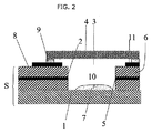
本発明の代替的なデバイスが図2に図示されている。本実施形態のデバイスは、下記の記述を除き、図1に図示して上述したデバイスと同一である。本実施形態では、デバイスは試験片Sを含む。試験片Sはいかなる形状およびサイズでもよいが、通常は、実質的に平坦な第1の面8を有する。試験片は、底面1および壁または複数の壁2により境界が定められるレセプタクル10を含む。本デバイスは、レセプタクルの壁内に作用電極5を有する電気化学セルをさらに含む。作用電極は通常、微小電極である。
An alternative device of the present invention is illustrated in FIG. The device of this embodiment is the same as the device shown in FIG. 1 and described above, except for the following description. In the present embodiment, the device includes a test piece S. The specimen S can be any shape and size, but typically has a
本実施形態のデバイスは、対向電極または参照電極、もしくは参照電極および対向電極の双方の働きをする擬似参照電極である電極11を含む。電極11はこれ以下では、擬似参照電極と呼ぶ。擬似参照電極は、試験片8の第1の面上に存在する擬似参照電極層11を含む。試験片の第1の面は、外面、すなわちレセプタクルの内面に曝された面ではなく、デバイスの外側に曝された面である。通常、擬似参照電極層は、レセプタクルまたは部分的なレセプタクル10を実質的に取り囲む。図2に図示されたとおり、擬似参照電極層は、第1の開口部3の外周部と接触していないことが好ましい。通常、擬似参照電極層は、第1の開口部の外周部から、少なくとも0.1mm、好ましくは少なくとも0.2mmの距離にある。しかし、擬似参照電極の少なくとも一部分が、第1の開口部の外周部から通常は2mm以下、たとえば1mmまたは0.5mm以下、好ましくは0.4mm以下にある。1つの実施形態では、擬似参照電極は、第1の開口部の外周部から0.01〜1.0mm、たとえば0.1〜0.5mm、または0.2〜0.4mmの距離で、レセプタクルまたは部分的なレセプタクルを実質的に取り囲む。代替的に、この距離は0.01〜0.3mm、または0.4〜0.7mmにすることができる。
The device of this embodiment includes an
擬似参照電極の厚さは通常、作用電極の厚さと同様であるか、またはそれよりも厚い。好適な最小の厚さは0.1μmであり、たとえば0.5μm、1μm、5μm、または10μmである。好適な最大の厚さは50μmであり、たとえば20μmまたは15μmである。 The thickness of the pseudo reference electrode is usually similar to or greater than the thickness of the working electrode. A suitable minimum thickness is 0.1 μm, for example 0.5 μm, 1 μm, 5 μm, or 10 μm. A suitable maximum thickness is 50 μm, for example 20 μm or 15 μm.
擬似参照電極11は通常、作用電極5の表面積と同様のサイズの、またはより広い、たとえば実質的に広い表面積を有する。通常、作用電極の表面積に対する擬似参照電極の表面積の比率は、少なくとも1:1、たとえば少なくとも2:1または少なくとも3:1であり、好ましくは、少なくとも4:1である。擬似参照電極は、たとえばマクロ電極にすることができる。作用電極の表面積に対する擬似参照電極の表面積の比率が1:1よりも大きい場合、このことは、擬似参照電極で発生する電気化学反応が、電流を制限しないことを確実にする助けとなる。擬似参照電極の実際の面積は、たとえば0.0001mm2〜150mm2、たとえば100mm2まで、または0.1mm2〜60mm2、たとえば1mm2〜50mm2である。
The
膜4は、任意の好適な取り付け手段9により、たとえば両面接着テープを用いて、デバイスに取り付けられる。通常、取り付け手段は、試験片の第1の面に、または擬似参照電極層に膜を取り付ける。図2に図示されたとおり、好ましい実施形態では、膜は、レセプタクル自体の外周部から離隔した位置で、擬似参照電極層11に取り付けられる。さらに、取り付け手段は、擬似参照電極層よりも、レセプタクル3の第1の開口部からより離れた距離にあり、擬似参照電極層のレセプタクルに近接したまたは取り囲んでいる面の少なくとも一部が、膜を通過した試料に曝されるようになされている。好ましくは、取り付け手段は、レセプタクルの外周部から少なくとも0.2mm、たとえば少なくとも0.3mmまたは少なくとも0.4mmにある。
The
図2に図示された実施形態では、反応体積は、レセプタクルの底面1および壁2、試験片8の面の一部分、擬似参照電極層11、取り付け手段9および膜4により画定される。この反応体積は、レセプタクルの体積、擬似参照電極層の位置および厚さ、および取り付け手段9の位置および厚さの変化により変動させることができる。好ましい反応体積は、少なくとも0.05μl、たとえば少なくとも0.1または少なくとも0.2μlである。反応体積が25μl以下、好ましくは5μl以下、たとえば3μl以下または2μl以下であることは、さらに好ましい。
In the embodiment illustrated in FIG. 2, the reaction volume is defined by the
本発明のデバイスで用いることができる電気化学セルに関するさらなる詳細は、WO 03/05319、英国特許出願第0414546.2号およびそれにより優先権を主張する国際出願(発明の名称はELECTRODE FOR ELECTROCHEMICAL SENSORであり、本出願と同日付で出願)に見ることができる。これらの出願の内容は、全体として参照することにより本明細書に組み込まれる。 Further details regarding electrochemical cells that can be used in the devices of the present invention can be found in WO 03/05319, British Patent Application No. 04145466.2 and the international application claiming priority thereby (ELECTRODE FOR ELECTROCHEMICAL SENSOR) Yes, filed on the same date as this application). The contents of these applications are incorporated herein by reference in their entirety.
本発明の方法は、膜を通してレセプタクル内部に液体試料を挿入することを含む。1つ以上の第2の開口部が存在して押しのけられた空気を逃がすことを可能にすることにより、レセプタクル内への試料の流れを助長することができる。レセプタクル内部へ試料が進入することで、反応を起こすことができるような方法で電気活性物質と試料との間での接触が発生する。 The method of the present invention includes inserting a liquid sample through the membrane and into the receptacle. One or more second openings may be present to allow escaped air to escape and thereby facilitate sample flow into the receptacle. Contact between the electroactive substance and the sample occurs in such a way that a reaction can occur as the sample enters the receptacle.
試料と電気活性物質との混合物は、作用電極に接触する。また、接触は通常、対向/参照電極と試料との間で発生する。これらの電極に接触する試料は、任意的には電気活性物質と混合される。 The mixture of sample and electroactive material contacts the working electrode. Also, contact typically occurs between the counter / reference electrode and the sample. The sample in contact with these electrodes is optionally mixed with an electroactive substance.
試料は、電気化学的試験が実行されるための任意の材料にすることができる。試料は液状、たとえば懸濁液または溶液である。本発明における試料として用いることができる材料の例は、水または水溶液、もしくは懸濁液、たとえば河川水、および生物学的試料、たとえば血液、血漿、血清または尿を含む。試験される試料の好ましい例は、血漿および血清を含む。 The sample can be any material for which an electrochemical test is performed. The sample is a liquid, such as a suspension or solution. Examples of materials that can be used as samples in the present invention include water or aqueous solutions or suspensions such as river water, and biological samples such as blood, plasma, serum or urine. Preferred examples of samples to be tested include plasma and serum.
試料は、膜を通してレセプタクル内部に挿入される。その他の方法、たとえば拡散が想定され得るが、試料は通常、膜を通した毛管流によって進入する。 The sample is inserted through the membrane and into the receptacle. The sample usually enters by capillary flow through the membrane, although other methods, such as diffusion, can be envisaged.
通常、電気活性物質は乾燥した形態であり、レセプタクル内部に試料を挿入するとき、電気活性物質は試料液体中に懸濁している。この再懸濁の段階を助長するために、湿潤剤を存在させてもよい。通常、試料を挿入する前に、レセプタクル内部に任意の湿潤剤が配置される。たとえば、湿潤剤は電気活性物質中に含まれていてもよい。 Usually, the electroactive substance is in a dry form, and when the sample is inserted into the receptacle, the electroactive substance is suspended in the sample liquid. A wetting agent may be present to facilitate this resuspension step. Usually, an optional wetting agent is placed inside the receptacle before inserting the sample. For example, a wetting agent may be included in the electroactive material.
レセプタクルの第1の開口部を覆って膜が存在することにより、レセプタクルに進入する試料の体積が実質上決定される。このようにして、試料の懸濁液中の電気活性物質の濃度を測定することができる。膜はさらに、レセプタクルの外への電気活性物質の拡散を規制する。このように、膜が電気活性物質をある時間だけレセプタクル内部に閉じ込める。本発明によれば、“レセプタクル内に閉じ込められる”または“レセプタクルの形をした電気化学セル内に閉じ込められる”の意味は、初期にレセプタクル内に存在する、実質的にすべての電気化学物質が、レセプタクル内部に引き続き収容されているということである。 The presence of the membrane over the first opening of the receptacle substantially determines the volume of the sample that enters the receptacle. In this way, the concentration of the electroactive substance in the sample suspension can be measured. The membrane further regulates the diffusion of the electroactive material out of the receptacle. In this way, the membrane traps the electroactive material within the receptacle for a period of time. According to the present invention, the meaning of “confined in a receptacle” or “confined in an electrochemical cell in the form of a receptacle” means that substantially all of the electrochemical material initially present in the receptacle is This means that it is still housed inside the receptacle.
本発明の好ましい実施形態では、この方法は、電気化学セルの両端に電位を付与することと、その結果の電気化学的な応答を測定することとをさらに含む。一般的には、電流が測定される。このように、この方法を用いて、レセプタクル内部に挿入された試料に、電気化学的な試験を実行することができる。通常、レセプタクル内部に試料を挿入することと、セルに電位を付与することとの間に、ある時間だけ、すなわちインキュベーション時間を経過させることが可能である。このインキュベーション期間により、電気活性物質が試料中に再度懸濁することができ、さらに試料が電気活性物質と反応することができる。インキュベーション期間は通常、1秒〜1分の範囲内であるが、当業者においては、使用される試料および電気活性物質に依存して、この範囲内に入れられるかまたは入れられない好適な期間を選択することが可能であろう。 In a preferred embodiment of the invention, the method further comprises applying a potential across the electrochemical cell and measuring the resulting electrochemical response. In general, current is measured. Thus, using this method, an electrochemical test can be performed on a sample inserted inside the receptacle. Usually, it is possible to allow a certain period of time, i.e., incubation time, between inserting the sample inside the receptacle and applying a potential to the cell. This incubation period allows the electroactive substance to be resuspended in the sample and allows the sample to react with the electroactive substance. The incubation period is usually in the range of 1 second to 1 minute, but those skilled in the art will have a suitable period that may or may not be within this range, depending on the sample and the electroactive substance used. It would be possible to choose.
セルの両端に電位が付与された後、その結果の電気化学的な応答、通常は電流が、電位が付与された時間から通常は約2分間まで、たとえば約1分間以内までに完了する測定により、1回または複数回測定される。 After a potential is applied across the cell, the resulting electrochemical response, usually a current, is measured by the completion of the potential from the time the potential is applied to typically about 2 minutes, for example, within about 1 minute. Measured once or multiple times.
通常、レセプタクル内部に電気活性物質を閉じ込めることは、制限された期間のみ効果がある。しかし、本発明によれば、電気活性物質は、少なくとも試料を挿入している間、レセプタクル内部に閉じ込められる。さらなる実施形態においては、電気活性物質は、試料が挿入されている間、インキュベーション期間の間、および好ましくはセルにより生成された電流を測定している間もまた、レセプタクル内部に閉じ込められる。このように、電気活性物質は好ましくは、レセプタクル内部に試料が挿入されてから少なくとも1分間、好ましくは少なくとも2分間、より好ましくは少なくとも5分間、レセプタクル内部に閉じ込められる。異なる膜であれば、異なる閉じ込め期間を提供することができる。たとえば、Whatman VF2膜は、およそ140秒の閉じ込め時間を提供する。 Usually, confining an electroactive material within a receptacle is only effective for a limited period of time. However, according to the present invention, the electroactive material is confined within the receptacle, at least during insertion of the sample. In a further embodiment, the electroactive substance is confined within the receptacle while the sample is inserted, during the incubation period, and preferably while measuring the current generated by the cell. Thus, the electroactive material is preferably confined within the receptacle for at least 1 minute, preferably at least 2 minutes, more preferably at least 5 minutes after the sample is inserted inside the receptacle. Different films can provide different confinement periods. For example, Whatman VF2 membranes provide a confinement time of approximately 140 seconds.
絶縁材の2層の間に作用電極材料の層(たとえばグラファイト層)を含む積層構造を形成することにより、本発明のデバイスを作ることができる。その後、この積層を通して孔を打ち抜き、このようにしてレセプタクルの壁を形成する。その後、任意的には対向電極を含む底面が付加される。積層の表面上に好適な材料の層をプリントすることにより、対向電極を代替的に備えることができる。レセプタクルの底面または壁に、1つ以上の第2の開口部が所望される場合、これらは任意の好適な手法により、たとえば孔を開けるかまたは孔を打ち抜くことにより、または多孔質膜を底面として用いることにより形成することができる。 By forming a laminated structure including a layer of working electrode material (eg, a graphite layer) between two layers of insulating material, the device of the present invention can be made. Thereafter, holes are punched through the stack, thus forming the walls of the receptacle. Thereafter, optionally a bottom surface including a counter electrode is added. A counter electrode can alternatively be provided by printing a layer of suitable material on the surface of the laminate. If one or more second openings are desired in the bottom surface or wall of the receptacle, these are any suitable technique, for example by drilling or punching holes, or with the porous membrane as the bottom surface. It can be formed by using.
その後、このようにして形成されたレセプタクル内部に、任意の好適な手法により電気活性物質が挿入される。通常、作用電極と接触しないような位置で、レセプタクル内部に電気活性物質が挿入される。これにより、作用電極の汚損を最小限にするか、または回避することが確実になる。電気活性物質は、確実に適所に留まるよう乾燥させることができる。たとえば、電気活性物質は、溶液または懸濁液の形状でレセプタクル内部に挿入され、その後自然乾燥させる。凍結乾燥、真空乾燥またはオーブン乾燥(加熱)により、電気活性物質を代替的に乾燥させてもよい。 Thereafter, the electroactive substance is inserted into the thus formed receptacle by any suitable method. Usually, an electroactive substance is inserted into the receptacle at a position where it does not come into contact with the working electrode. This ensures that fouling of the working electrode is minimized or avoided. The electroactive material can be dried to ensure that it remains in place. For example, the electroactive material is inserted into the receptacle in the form of a solution or suspension and then allowed to air dry. The electroactive material may alternatively be dried by freeze drying, vacuum drying or oven drying (heating).
本発明の1つの実施形態では、電気活性物質は、レセプタクルの底面を形成する基板上にあらかじめ被覆されている。これは、平面基板上に電気活性物質を直接被覆するか、または基板にくぼみを形成してくぼみ内部に電気活性物質を排出することにより行うことができる。通常、電気活性物質はその後、所定の位置で乾燥され、このようにして被覆された基板は、レセプタクルの壁に接合される。電気活性物質が基板のくぼみ内部に挿入された場合、くぼみは通常、最後の電気化学セルの断面と一致する断面を有する。このようにしてくぼみは、電気化学セルにより形成されたレセプタクルの底面部を作る。本実施形態は、セルを作り出す間つねに、電気活性物質が作用電極から離隔した状態に保たれるという利点を有する。したがって、セルが用いられる前に、電気活性物質と作用電極との間の接触は最小限になる。ひいてはこれにより、作用電極の汚損が最小限になる。 In one embodiment of the invention, the electroactive material is pre-coated on a substrate that forms the bottom surface of the receptacle. This can be done by coating the electroactive material directly on the planar substrate, or by forming a recess in the substrate and discharging the electroactive material into the recess. Usually, the electroactive material is then dried in place and the substrate thus coated is bonded to the wall of the receptacle. When the electroactive material is inserted inside the substrate recess, the recess typically has a cross section that matches the cross section of the last electrochemical cell. In this way, the indentation creates the bottom surface of the receptacle formed by the electrochemical cell. This embodiment has the advantage that the electroactive substance is always kept away from the working electrode during the creation of the cell. Thus, contact between the electroactive material and the working electrode is minimized before the cell is used. This in turn minimizes contamination of the working electrode.
電気活性物質の挿入に続いて、レセプタクルの第1の開口部に膜が取り付けられる。これは、任意の好適な手段により、たとえば両面接着剤を用いてレセプタクルの上面に膜を接着することにより達成することができる。 Following insertion of the electroactive material, a membrane is attached to the first opening of the receptacle. This can be accomplished by any suitable means, for example by adhering the membrane to the top surface of the receptacle using a double-sided adhesive.
図1に図示されたような、セルを作り出すためのプロセスに関するさらなる詳細は、WO 03/056319、英国特許出願第0414546.2号およびそれにより優先権を主張する国際出願(発明の名称はELECTRODE FOR ELECTROCHEMICAL SENSORであり、本出願と同日付で出願)から得ることができ、これらはそれぞれ上記にて参照されている。 For further details regarding the process for creating the cell as illustrated in FIG. 1, see WO 03/056319, UK patent application No. 04145466.2 and the international application claiming priority thereby (the title of the invention is ELECTRODE FOR ELECTROCHEMICAL SENSOR, filed on the same date as this application), each of which is referenced above.
好ましい実施形態では、本発明の方法は、体液試料が健康かまたは虚血性かを測定するための電気化学的な滴定試験において用いられる。また、患者から採取された体液試料に対して試験を実行することにより、この試験を患者における虚血の診断に用いることができる。 In a preferred embodiment, the method of the invention is used in an electrochemical titration test to determine whether a body fluid sample is healthy or ischemic. In addition, by performing a test on a body fluid sample collected from a patient, this test can be used for diagnosis of ischemia in the patient.
本実施形態では、電気活性物質は、本発明の方法を用いて、虚血性の試料と健康な試料とを電気化学的に判別することが可能である遷移金属塩を含む。当業者においては、(i)健康であることが既知である試料と(ii)虚血性であることが既知である試料とに対して、本発明の方法を実行することにより、遷移金属塩が好適であるかどうかを測定することが可能であろう。好適な遷移金属塩により、試料(ii)について読み取る、試料(i)よりも高い電流が提供される。試料中の、健康なおよび虚血的に変えられたタンパク質(たとえばアルブミン)に対する遷移金属の結合能力の相違は、このタイプの試験の機構において重要であろう。したがって、通常は、遷移金属は、健康なタンパク質、たとえば血液内に存在するタンパク質と結合する能力があるが、虚血性イベントに続くこれらのタンパク質に対しては、より低い結合親和性を有するかまたは結合しない。たとえば、遷移金属は健康なアルブミンと結合する能力を有することができるが、虚血性イベントに続いて変えられたアルブミンに対しては、より低い結合親和性を有するかまたは結合しない。しかし本発明は、この理論に制約されるものではない。好適な遷移金属塩の例は、マンガン、鉄、コバルト、銅、およびニッケル塩を含む。コバルト(II)塩が好ましい。 In this embodiment, the electroactive substance includes a transition metal salt that can electrochemically distinguish between an ischemic sample and a healthy sample using the method of the present invention. One skilled in the art will recognize that the transition metal salt is obtained by performing the method of the present invention on (i) a sample known to be healthy and (ii) a sample known to be ischemic. It may be possible to determine whether it is suitable. A suitable transition metal salt provides a higher current than sample (i) reading for sample (ii). Differences in the ability of the transition metal to bind to healthy and ischemically altered proteins (eg, albumin) in the sample may be important in the mechanism of this type of test. Thus, normally transition metals are capable of binding healthy proteins, such as those present in the blood, but have a lower binding affinity for these proteins following an ischemic event or Do not combine. For example, a transition metal can have the ability to bind healthy albumin, but has a lower binding affinity or does not bind to albumin altered following an ischemic event. However, the present invention is not limited to this theory. Examples of suitable transition metal salts include manganese, iron, cobalt, copper, and nickel salts. Cobalt (II) salts are preferred.
塩は一般的に、水中で解離して遷移金属イオンおよびアニオンを与えるものである。したがって、水に溶解して溶解時に解離する塩を提供する、あらゆるアニオンを用いることができる。本発明において用いるために好適な塩の例は、ハロゲン化物、たとえばクロリドを含む。好ましい塩は、塩化コバルト(II)である。 Salts are generally those that dissociate in water to give transition metal ions and anions. Thus, any anion that provides a salt that dissolves in water and dissociates upon dissolution can be used. Examples of suitable salts for use in the present invention include halides such as chloride. A preferred salt is cobalt (II) chloride.
この試験は滴定法であるため、試料との反応に利用できる遷移金属塩の量が既知である必要がある。本発明の方法では、セル内に存在する電気活性物質の量の精確な測定が可能となるため、このような状況において特に有用である。 Since this test is a titration method, the amount of transition metal salt available for reaction with the sample needs to be known. The method of the present invention is particularly useful in such situations because it allows accurate measurement of the amount of electroactive material present in the cell.
電気活性物質中に存在する遷移金属塩の好ましい量は、塩および試験される試料の特性の他に、物質が接触しようとする試料の体積に依存する。一般的に、遷移金属がコバルト(II)である場合、試験される試料と混合されたとき(たとえば乾燥した電気活性物質が、試料中に再度懸濁されたとき)、その結果の混合物中のコバルト(II)の濃度が0.1〜100mmoldm−3になるような量のコバルト(II)塩が存在する。試験される試料が血漿である場合、好ましくは、試験される試料と混合されたとき、その結果の混合物中のコバルト(II)の濃度が1〜20、好ましくは4.25〜5.25mmoldm−3になるような量のコバルト(II)塩が存在する。混合物中のコバルト(II)塩のもっとも好ましい濃度は、4.5〜5.0、たとえばおよそ4.75mmoldm−3である。このような濃度は、たとえば5.5mmoldm−3以上(たとえば30〜40mmoldm−3)のコバルト(II)塩を含む電気活性物質を用い、続いて電気活性物質を、試料自体の既知である体積で希釈する(たとえば、電気活性物質:試料を1:1〜1:20、たとえば1:5〜1:10の比率で用いる)ことで達成することができる。たとえば、35.6mmoldm−3のコバルト(II)塩の濃度を有する0.2μlの電気活性物質を、本発明のデバイス内部で、またはその上で乾燥させ、続いて1.5μlの試料中に再度懸濁させることができ、その結果の混合物中におよそ4.75mmoldm−3の濃度が備えられる。 The preferred amount of transition metal salt present in the electroactive material depends on the volume of the sample that the material is to contact, in addition to the salt and the properties of the sample being tested. In general, when the transition metal is cobalt (II), when mixed with the sample to be tested (eg, when the dried electroactive material is resuspended in the sample), the resulting mixture in the mixture An amount of cobalt (II) salt is present such that the concentration of cobalt (II) is 0.1-100 mmol dm −3 . If the sample to be tested is plasma, preferably the concentration of cobalt (II) in the resulting mixture when mixed with the sample to be tested is 1-20, preferably 4.25-5.25 mmol dm − It becomes 3 such amount of cobalt (II) salt is present. The most preferred concentration of cobalt (II) salt in the mixture is 4.5 to 5.0, for example approximately 4.75 mmol dm −3 . Such a concentration is obtained using, for example, an electroactive substance containing a cobalt (II) salt of 5.5 mmoldm −3 or more (eg, 30-40 mmoldm −3 ), and then the electroactive substance in a known volume of the sample itself. It can be achieved by diluting (eg using electroactive substance: sample in a ratio of 1: 1 to 1:20, eg 1: 5 to 1:10). For example, 0.2 μl of electroactive material having a concentration of 35.6 mmol dm −3 cobalt (II) salt is dried inside or on the device of the present invention and subsequently again in a 1.5 μl sample. The resulting mixture can be suspended with a concentration of approximately 4.75 mmol dm −3 .
さらに、電気活性物質は好ましくは、電極領域に依存する電流を有する電極領域正常化剤を含む。通常、電極領域正常化剤は、試料が虚血性であるかどうかに依存しない電流を有する。遷移金属塩により作り出される電流の電気化学的測定は、測定のために用いられる電極の表面積に依存する。したがって、遷移金属により生成される電流の、より正確な測定を得るために、電極領域正常化剤を用いて、測定値を正常化することが望ましい。電極領域正常化剤が、電極領域について測定された電流を完璧および正確に正常化することは、好ましくはあるが本質ではない。しかし、正常化剤は、電極領域での変動の原因となる、ある程度の補正を備える。したがって、本発明の関連では、‘正常化する’の意味は、ある程度の補正を備えるということである。 Furthermore, the electroactive substance preferably comprises an electrode region normalizing agent having a current dependent on the electrode region. Usually, the electrode region normalizing agent has a current that does not depend on whether the sample is ischemic. The electrochemical measurement of the current produced by the transition metal salt depends on the surface area of the electrode used for the measurement. Therefore, in order to obtain a more accurate measurement of the current generated by the transition metal, it is desirable to normalize the measured value using an electrode region normalizing agent. It is preferably but not essential that the electrode area normalizing agent perfectly and accurately normalizes the current measured for the electrode area. However, the normalizing agent provides some correction that causes fluctuations in the electrode area. Therefore, in the context of the present invention, the meaning of 'normalize' is to provide a certain amount of correction.
電極領域の正常化は、電極領域正常化剤と遷移金属電流の測定との、実質的に同時な電気化学的反応により作り出される電流を測定することにより行うことができる。両方の測定のために、同一の電極が用いられる。その後、遷移金属の酸化/還元による電流の測定は、電極領域正常化剤のために得られる測定を用いて、任意の好適な手法により正常化することができる。 The normalization of the electrode region can be performed by measuring a current produced by an electrochemical reaction of the electrode region normalizing agent and the transition metal current measured substantially simultaneously. The same electrode is used for both measurements. Thereafter, the current measurement by oxidation / reduction of the transition metal can be normalized by any suitable technique using the measurements obtained for the electrode region normalizing agent.
たとえば、値ITM/INAを用いて、より精確な結果を得ることができ、ここでITMは遷移金属の酸化/還元のために得られる電流であり、INAは電極領域正常化剤の酸化/還元のために得られる電流である。遷移金属電流のためのこの正常化された値を用いることにより、電極領域内での変化による測定結果の誤差を最小限にすることができる。 For example, the value I TM / I NA can be used to obtain more accurate results, where I TM is the current obtained for oxidation / reduction of the transition metal and I NA is the electrode region normalizing agent. Is the current obtained for the oxidation / reduction of. By using this normalized value for the transition metal current, measurement error due to changes in the electrode area can be minimized.
電極領域正常化剤は、遷移金属とは異なる酸化/還元電位を有する。さらに、通常は、タンパク質、たとえばアルブミンを含む血液中のタンパク質とは結合しないか、またはごく弱く結合する。電極領域正常化剤は、たとえばタンパク質により外圏錯体のみを形成することができる。電極領域正常化剤は通常、重金属、たとえばルテニウムまたはオスミウムを含む。したがって、好適な電極領域正常化剤の例は、ルテニウムまたはオスミウムの複合体、たとえばアミノ系リガンドとの複合体を含む。好ましい電極領域正常化剤は、塩化ルテニウムヘキサミンおよび塩化オスミウムヘキサミン、特に塩化ルテニウムヘキサミンを含む。 The electrode region normalizing agent has an oxidation / reduction potential different from that of the transition metal. Furthermore, it usually does not bind or binds very weakly to proteins, such as proteins in blood, including albumin. The electrode region normalizing agent can form only an outer sphere complex with a protein, for example. Electrode region normalizing agents typically include heavy metals such as ruthenium or osmium. Thus, examples of suitable electrode region normalizing agents include complexes with ruthenium or osmium, such as complexes with amino-based ligands. Preferred electrode area normalizing agents include ruthenium hexamine chloride and osmium hexamine chloride, especially ruthenium hexamine chloride.
一般的に、試験される試料と混合されたとき(たとえば乾燥した電気活性物質が、試料中に再度懸濁されたとき)、その結果の混合物中の電極領域正常化剤の濃度が、0.1〜100mmoldm−3、好ましくは1〜10mmoldm−3、より好ましくは3〜3.5、またはおよそ3.2mmoldm−3になるような量の電極領域正常化剤が存在する。このような濃度は、たとえば5mmoldm−3よりも多く(たとえば20〜30mmoldm−3)を含む電気活性物質を用い、続いて電気活性物質を、試料自体の既知である体積で希釈する(たとえば、電気活性物質:試料を1:1〜1:20、たとえば1:5〜1:10の比率で用いる)ことで達成することができる。たとえば、24mmoldm−3の電極領域正常化剤の濃度を有する0.2μlの電気活性物質を、本発明のデバイス内部で、またはその上で乾燥させ、続いて1.5μlの試料中に再度懸濁させることができ、その結果の混合物中におよそ3.2mmoldm−3の濃度が備えられる。 Generally, when mixed with the sample to be tested (eg, when the dried electroactive material is resuspended in the sample), the concentration of the electrode region normalizing agent in the resulting mixture is 0. An amount of electrode region normalizing agent is present such that it is between 1 and 100 mmoldm −3 , preferably between 1 and 10 mmoldm −3 , more preferably between 3 and 3.5, or approximately 3.2 mmoldm −3 . Such a concentration uses, for example, an electroactive material containing more than 5 mmol dm −3 (eg, 20-30 mmol dm −3 ), and then dilutes the electroactive material with a known volume of the sample itself (eg, electric Active substance: sample is used in a ratio of 1: 1 to 1:20, eg 1: 5 to 1:10). For example, 0.2 μl of electroactive material having a concentration of 24 mmoldm −3 electrode area normalizing agent is dried inside or on the device of the invention and subsequently resuspended in 1.5 μl of sample. A concentration of approximately 3.2 mmol dm −3 is provided in the resulting mixture.
本発明の本実施形態の電気活性物質は通常、塩化物塩または硫酸塩、たとえば上記にて例示されたものを含む。カリウムまたは塩化ナトリウム、もしくは硫酸ナトリウムが好ましい。塩は通常、試験される試料と混合されたとき、その結果の混合中の塩の濃度が、1〜300mmoldm−3、好ましくは6〜60mmoldm−3、より好ましくは10〜30mmoldm−3であるような量で存在する。 The electroactive materials of this embodiment of the present invention typically include chloride salts or sulfate salts such as those exemplified above. Potassium or sodium chloride or sodium sulfate is preferred. The salt is usually mixed with the sample to be tested so that the concentration of the salt in the resulting mixture is 1 to 300 mmol dm −3 , preferably 6 to 60 mmol dm −3 , more preferably 10 to 30 mmol dm −3. Present in the correct amount.
また、電気活性物質は通常、湿潤剤、たとえばポリビニルピロリドン(PVP)を含む。PVPは通常、電気活性物質と、試験される試料とが混合されたとき、その結果の混合中のPVPの濃度が、0.01〜30%w/v、たとえば0.2〜5%w/v、好ましくは0.7%w/vであるような量で存在する。電気活性物質自体は、より高い濃度のPVPを有し、この濃度はその後、既知である体積の試料により希釈されて、必要とされる濃度を提供する。ポリビニルピロリドンの濃度が高すぎる場合、再懸濁はゆっくりと発生する。このように、通常は5%w/v以下の、好ましくは2%w/vまたは1.5%w/v以下の、より好ましくは1%w/v以下のポリビニルピロリドンが存在する。しかし、ポリビニルピロリドンの濃度が低すぎる場合、十分な濡れ性が備えられない。 The electroactive material typically also includes a wetting agent such as polyvinyl pyrrolidone (PVP). PVP typically has a concentration of PVP in the resulting mixture of 0.01-30% w / v, such as 0.2-5% w / v when the electroactive substance and the sample to be tested are mixed. v, preferably in an amount such that it is 0.7% w / v. The electroactive material itself has a higher concentration of PVP, which is then diluted with a known volume of sample to provide the required concentration. If the concentration of polyvinylpyrrolidone is too high, resuspension occurs slowly. Thus, usually 5% w / v or less, preferably 2% w / v or 1.5% w / v or less, more preferably 1% w / v or less of polyvinylpyrrolidone is present. However, when the concentration of polyvinylpyrrolidone is too low, sufficient wettability is not provided.
ポリビニルピロリドンは通常、100,000までの平均分子量を有する。好ましい平均分子量は、少なくとも5,000、より好ましくは少なくとも7,500である。さらに分子量は、好ましくは50,000以下、より好ましくは20,000以下、たとえば15,000以下または12,500以下である。好ましい平均分子量はおよそ10,000である。そのような分子量を有するポリビニルピロリドンを用いることは、電気活性物質のより迅速な再懸濁に至るものと考えられてきた。 Polyvinylpyrrolidone usually has an average molecular weight of up to 100,000. A preferred average molecular weight is at least 5,000, more preferably at least 7,500. Furthermore, the molecular weight is preferably 50,000 or less, more preferably 20,000 or less, for example 15,000 or less or 12,500 or less. A preferred average molecular weight is approximately 10,000. The use of polyvinylpyrrolidone having such a molecular weight has been thought to lead to a more rapid resuspension of the electroactive material.
電気化学的測定は好ましくは、6〜8のpHで、たとえば6.5〜7.5、好ましくは6.8〜7.2のpHで行われる。試験される試料中にいったん再懸濁された電気活性物質のpHが、実質的に6〜8の範囲内に留まることを確実にするために、緩衝剤を電気活性物質中に含むことができる。緩衝剤は、電気活性物質が水中に懸濁されたとき、6〜8のpHを提供するものである必要がある。実行される測定の電位範囲を超えて電気化学的に活性でない、任意の緩衝剤を用いることができる。当業者においては、好適な緩衝剤は既知であり、使用可能な緩衝剤の一例は、(N−モルホリノ)プロパンスルホン酸(MOPS)である。 The electrochemical measurement is preferably carried out at a pH of 6-8, for example at a pH of 6.5-7.5, preferably 6.8-7.2. A buffer may be included in the electroactive material to ensure that the pH of the electroactive material once resuspended in the sample being tested remains substantially within the range of 6-8. . The buffering agent needs to provide a pH of 6-8 when the electroactive material is suspended in water. Any buffer that is not electrochemically active beyond the potential range of the measurement to be performed can be used. Suitable buffering agents are known to those skilled in the art, and one example of a buffering agent that can be used is (N-morpholino) propanesulfonic acid (MOPS).
好ましい電気活性物質は、マンガン、鉄、コバルト、ニッケルまたは銅塩;ルテニウムまたはオスミウムの複合体;湿潤剤;任意的には塩化物塩または硫酸塩;および任意的には緩衝剤を含む。特に好ましい組成は、コバルト塩、ルテニウムまたはオスミウムの複合体;ポリビニルピロリドン;任意的には塩化物塩または硫酸塩;および任意的には緩衝剤を含む。好ましい実施態様では、緩衝剤はこれらの組成中に存在する。電気活性物質に関するさらなる詳細は、英国特許出願第0414551.2号およびそれにより優先権を主張する国際出願(本出願と同日付で出願され、発明の名称はELECTROCHEMICAL SENSOR)に見られる。これらの出願の内容は、全体として参照することにより本明細書に組み込まれる。 Preferred electroactive materials include manganese, iron, cobalt, nickel or copper salts; ruthenium or osmium complexes; wetting agents; optionally chloride or sulfate salts; and optionally buffering agents. Particularly preferred compositions comprise a cobalt salt, ruthenium or osmium complex; polyvinylpyrrolidone; optionally a chloride or sulfate salt; and optionally a buffer. In preferred embodiments, buffering agents are present in these compositions. Further details regarding electroactive materials can be found in UK patent application No. 0414551.2 and the international application claiming priority thereby (filed on the same date as this application and named ELECTROCHEMICAL SENSOR). The contents of these applications are incorporated herein by reference in their entirety.
本発明はまた、上述の滴定式の電気化学的試験に用いることができるデバイスを提供する。本デバイスは、レセプタクルの形をした電気化学セル、たとえば上述のような電気化学セルを含む。任意的には、本発明のデバイスは、2個以上の電気化学セルを含むことができる。本発明のデバイスの電気活性物質は遷移金属塩を含み、好ましい電気活性物質は、上述したものである。 The present invention also provides a device that can be used for the titration electrochemical test described above. The device includes an electrochemical cell in the form of a receptacle, such as an electrochemical cell as described above. Optionally, the device of the present invention can comprise two or more electrochemical cells. The electroactive material of the device of the present invention comprises a transition metal salt, and preferred electroactive materials are those described above.
実施例
実施例1
電気化学的試験を実行するために、図2に図示されたタイプのデバイスが用いられたが、ここで作用電極は炭素電極であり、擬似参照電極はAg/AgCl電極である。壁、接着剤および膜の底表面により画定されたレセプタクルの体積は1.5ulであった。デバイス上に膜が取り付けられる前に、35.6mMのCoCl2、24mMの塩化ルテニウムヘキサミンおよび5%w/vのPVP内の150mMのKCl、ならびにMOPS緩衝剤(pH7.0を備える)を含む、0.2ulの試薬混合物が、デバイスのレセプタクル内部に挿入されて乾燥された。使用された膜はWhatman VF2膜であった。
Example
Example 1
To perform the electrochemical test, a device of the type illustrated in FIG. 2 was used, where the working electrode is a carbon electrode and the pseudo reference electrode is an Ag / AgCl electrode. The volume of the receptacle defined by the walls, the adhesive and the bottom surface of the membrane was 1.5 ul. Before the membrane is mounted on the device, it includes 35.6 mM CoCl 2 , 24 mM ruthenium hexamine chloride and 150 mM KCl in 5% w / v PVP, and MOPS buffer (with pH 7.0). 0.2 ul of the reagent mixture was inserted inside the device receptacle and dried. The membrane used was a Whatman VF2 membrane.
電気化学セルに、くぼみの体積を充填する1.5ulの標準的な血漿が付与され、試薬混合物を血漿中に再度懸濁させた。1.5ulの血漿の体積中におけるCoの最終的な再懸濁の濃度は、4.75mMであり、対応するRuの濃度は3.2mMであった。 The electrochemical cell was given 1.5 ul of standard plasma filling the volume of the well and the reagent mixture was resuspended in the plasma. The final Co resuspension concentration in the 1.5 ul plasma volume was 4.75 mM and the corresponding Ru concentration was 3.2 mM.
時間により変動する電位をセルに付与し、付与された電位を−0.4Vまで低下させ、その後1.7Vまで上昇させた。電位スキャンの間、電流が測定され、その結果は図3に図示されている。 A potential varying with time was applied to the cell, and the applied potential was reduced to -0.4V and then increased to 1.7V. During the potential scan, the current is measured and the result is illustrated in FIG.
実施例2
本デバイスに70ulの全血が付与されたことを除き、実施例1の方法が、レセプタクル内部に血漿を通過させるWhatman VF2膜を用いて繰り返された。およそ1.5ulの体積がセルの体積を充填する。測定電位を付与する前に、100秒の濡れ時間が与えられた。
Example 2
The method of Example 1 was repeated with a Whatman VF2 membrane that allowed plasma to pass inside the receptacle, except that 70 ul of whole blood was applied to the device. A volume of approximately 1.5 ul fills the cell volume. Before applying the measurement potential, a wetting time of 100 seconds was given.
実施例1と同様に、測定電位を付与する間、電流が測定され、電極領域に向かう測定された酸化コバルトの電流を正常化するために、I(Co):I(Ru)の比率がさらに計算された。血漿試料を付加した後、I(Co):I(Ru)の比率についての同様の測定が、140秒、180秒および220秒の時点で行われ、その結果が図4に図示されている。この図は、I(Co):I(Ru)の比率をy軸に示し、血漿試料を付加した後の時間をx軸に示している。この例が実証するとおり、測定期間中にわたり実質的な定電流が達成され、この期間中は、レセプタクルの体積内部の試薬の濃度が実質的に一定であることを示している。 As in Example 1, the current is measured while applying the measured potential, and the ratio of I (Co): I (Ru) is further increased to normalize the measured cobalt oxide current toward the electrode region. calculated. After adding the plasma sample, similar measurements for the ratio of I (Co): I (Ru) were made at 140, 180 and 220 seconds and the results are illustrated in FIG. The figure shows the ratio of I (Co): I (Ru) on the y-axis and the time after adding the plasma sample on the x-axis. As this example demonstrates, a substantially constant current is achieved over the measurement period, indicating that the concentration of reagent within the volume of the receptacle is substantially constant during this period.
各種の特定の実施形態および例を参照して、本発明を説明してきた。本発明は記載された特定の実施形態および例に限るものではないことが理解されよう。 The invention has been described with reference to various specific embodiments and examples. It will be understood that the invention is not limited to the specific embodiments and examples described.
Claims (15)
(a)レセプタクルの形をした電気化学セルであって、レセプタクルが、レセプタクル内部に試料が進入することができるようにするための第1の開口部と、進入した試料により押しのけられた空気を逃がすことができるようにするための第2の開口部とを有し、電気化学セルが作用電極と対向電極とを有する電気化学セルを備えることと、
(b)レセプタクル内部に収容される電気活性物質を備えることと、
(c)レセプタクルの第1の開口部を覆う、1つ以上の層を含む透過性または半透過性の膜を備えることと、
(d)(1)電気活性物質と(2)試料とが互いに、および前記作用電極と接触するように、膜を通してレセプタクル内部に試料を挿入することと、
を含み、
ステップ(d)の間に、電気活性物質がレセプタクル内に閉じ込められる方法。 A method of confining an electroactive substance within an electrochemical cell in the form of a receptacle,
(A) An electrochemical cell in the form of a receptacle, where the receptacle allows a first opening for allowing the sample to enter the interior of the receptacle and air displaced by the entered sample A second opening for allowing the electrochemical cell to comprise an electrochemical cell having a working electrode and a counter electrode;
(B) comprising an electroactive material contained within the receptacle;
(C) comprising a permeable or semi-permeable membrane comprising one or more layers covering the first opening of the receptacle;
(D) (1) inserting the sample into the receptacle through the membrane so that the electroactive substance and (2) the sample are in contact with each other and the working electrode;
Including
A method wherein the electroactive material is confined within the receptacle during step (d).
(i) 電気化学セルの両端に電位を付与することと、
(ii)その結果の電気化学的応答を測定することと、
をさらに含み、
ステップ(i)および(ii)の間に、電気活性物質がレセプタクル内に閉じ込められる、請求項1記載の方法。 A method for electrochemically testing a sample,
(I) applying a potential to both ends of the electrochemical cell;
(Ii) measuring the resulting electrochemical response;
Further including
The method of claim 1, wherein during steps (i) and (ii), the electroactive material is confined within the receptacle.
− 電極領域に依存する電流を有する電極領域正常化剤と、
− 塩化物塩または硫酸塩と、
− 湿潤剤と、
から選択された1つ以上の成分をさらに含む、請求項3〜5のいずれか一項記載の方法。 Electroactive substances
-An electrode area normalizing agent having a current dependent on the electrode area;
-Chloride salt or sulfate salt;
-A wetting agent;
6. The method according to any one of claims 3-5, further comprising one or more components selected from.
レセプタクルが、第1の開口部を含み、および電気化学セルの形状であり、
膜が、試料に対して不透過性であり、およびレセプタクルの第1の開口部を覆うように位置付けされ、
試料の挿入前に、電気活性物質がレセプタクル内に収容される膜。 Use of a membrane comprising one or more layers for confining an electroactive material within the receptacle following insertion of a liquid sample into the receptacle;
The receptacle includes a first opening and is in the shape of an electrochemical cell;
The membrane is impermeable to the sample and positioned to cover the first opening of the receptacle;
A membrane in which an electroactive substance is contained in a receptacle prior to sample insertion.
− 請求項3、4、6または7のいずれか一項に定められたような電気活性物質であって、レセプタクル内に収容される電気活性物質と、
− レセプタクルの第1の開口部を覆うように位置付けられた、1つ以上の層を含む透過性または半透過性の膜と、
− セルの両端に電圧を印加するための手段と、
− その結果の、セルの両端での電気化学的な応答を測定するための手段と、
を含むデバイス。 -An electrochemical cell in the form of a receptacle, where the receptacle allows a first opening to allow the sample to enter the receptacle and escape air displaced by the sample that has entered. An electrochemical cell having a second opening to allow the electrochemical cell to have a working electrode and a counter electrode;
An electroactive substance as defined in any one of claims 3, 4, 6 or 7, which is contained in a receptacle;
-A permeable or semi-permeable membrane comprising one or more layers positioned to cover the first opening of the receptacle;
-Means for applying a voltage across the cell;
-A means for measuring the resulting electrochemical response at both ends of the cell;
Including device.
Applications Claiming Priority (2)
| Application Number | Priority Date | Filing Date | Title |
|---|---|---|---|
| GBGB0414550.4A GB0414550D0 (en) | 2004-06-29 | 2004-06-29 | Electrochemical sensing method |
| PCT/GB2005/002558 WO2006000829A2 (en) | 2004-06-29 | 2005-06-29 | Electrochemical sensing method |
Publications (2)
| Publication Number | Publication Date |
|---|---|
| JP2008505338A true JP2008505338A (en) | 2008-02-21 |
| JP2008505338A5 JP2008505338A5 (en) | 2008-06-19 |
Family
ID=32843238
Family Applications (1)
| Application Number | Title | Priority Date | Filing Date |
|---|---|---|---|
| JP2007519866A Ceased JP2008505338A (en) | 2004-06-29 | 2005-06-29 | Electrochemical detection method |
Country Status (5)
| Country | Link |
|---|---|
| US (1) | US20070259262A1 (en) |
| EP (1) | EP1848988A2 (en) |
| JP (1) | JP2008505338A (en) |
| GB (1) | GB0414550D0 (en) |
| WO (1) | WO2006000829A2 (en) |
Families Citing this family (5)
| Publication number | Priority date | Publication date | Assignee | Title |
|---|---|---|---|---|
| GB0414548D0 (en) | 2004-06-29 | 2004-08-04 | Oxford Biosensors Ltd | Electrode preconditioning |
| GB0526051D0 (en) * | 2005-12-21 | 2006-02-01 | Oxford Biosensors Ltd | Cholesterol sensor |
| US20100030052A1 (en) * | 2008-07-31 | 2010-02-04 | Bommakanti Balasubrahmanya S | Analyte sensors comprising plasticizers |
| US20150051064A1 (en) * | 2012-02-21 | 2015-02-19 | Georgetown University | Polyvinylpyrrolidone (pvp) for enhancing the activity and stability of platinum-based electrocatalysts |
| DE202015101346U1 (en) | 2015-03-17 | 2016-06-22 | Gea Mechanical Equipment Gmbh | Separator with drum tool |
Citations (7)
| Publication number | Priority date | Publication date | Assignee | Title |
|---|---|---|---|---|
| JPH03505785A (en) * | 1989-04-04 | 1991-12-12 | ウルバン ゲラルト | Micro multi-electrode structure |
| JP2002340839A (en) * | 2001-05-22 | 2002-11-27 | Matsushita Electric Ind Co Ltd | Biosensor |
| JP2003065997A (en) * | 2001-06-14 | 2003-03-05 | Matsushita Electric Ind Co Ltd | Biosensor |
| WO2003056319A2 (en) * | 2001-12-21 | 2003-07-10 | Oxford Biosensors Limited | Micro-band electrode |
| JP2003254933A (en) * | 2002-03-01 | 2003-09-10 | Matsushita Electric Ind Co Ltd | Biosensor |
| WO2005121762A1 (en) * | 2004-06-14 | 2005-12-22 | Oxford Biosensors Ltd | Micro-band electrode manufacturing method |
| WO2006000823A2 (en) * | 2004-06-29 | 2006-01-05 | Oxford Biosensors Limited | Composition and electrochemical sensor for detecting ischaemia |
Family Cites Families (8)
| Publication number | Priority date | Publication date | Assignee | Title |
|---|---|---|---|---|
| US4795542A (en) * | 1986-04-24 | 1989-01-03 | St. Jude Medical, Inc. | Electrochemical concentration detector device |
| US5196340A (en) * | 1989-08-04 | 1993-03-23 | Nec Corporation | Enzyme electrode containing an enzyme and a coenzyme immobilized in separate layers of a membrane |
| GB9312578D0 (en) * | 1993-06-18 | 1993-08-04 | Isis Innovation | Determining gas concentration |
| US6174420B1 (en) * | 1996-11-15 | 2001-01-16 | Usf Filtration And Separations Group, Inc. | Electrochemical cell |
| US6444115B1 (en) * | 2000-07-14 | 2002-09-03 | Lifescan, Inc. | Electrochemical method for measuring chemical reaction rates |
| AU2002352959B2 (en) * | 2001-11-26 | 2008-04-10 | Ischemia Technologies, Inc. | Electrochemical detection of ischemia |
| CN100339702C (en) * | 2002-03-01 | 2007-09-26 | 松下电器产业株式会社 | Biosensor |
| US20060008581A1 (en) * | 2004-07-09 | 2006-01-12 | Mark Hyland | Method of manufacturing an electrochemical sensor |
-
2004
- 2004-06-29 GB GBGB0414550.4A patent/GB0414550D0/en not_active Ceased
-
2005
- 2005-06-29 JP JP2007519866A patent/JP2008505338A/en not_active Ceased
- 2005-06-29 US US11/630,739 patent/US20070259262A1/en not_active Abandoned
- 2005-06-29 EP EP05756441A patent/EP1848988A2/en not_active Withdrawn
- 2005-06-29 WO PCT/GB2005/002558 patent/WO2006000829A2/en active Application Filing
Patent Citations (8)
| Publication number | Priority date | Publication date | Assignee | Title |
|---|---|---|---|---|
| JPH03505785A (en) * | 1989-04-04 | 1991-12-12 | ウルバン ゲラルト | Micro multi-electrode structure |
| JP2002340839A (en) * | 2001-05-22 | 2002-11-27 | Matsushita Electric Ind Co Ltd | Biosensor |
| JP2003065997A (en) * | 2001-06-14 | 2003-03-05 | Matsushita Electric Ind Co Ltd | Biosensor |
| WO2003056319A2 (en) * | 2001-12-21 | 2003-07-10 | Oxford Biosensors Limited | Micro-band electrode |
| JP2005513500A (en) * | 2001-12-21 | 2005-05-12 | オックスフォード バイオセンサーズ リミテッド | Micro band electrode |
| JP2003254933A (en) * | 2002-03-01 | 2003-09-10 | Matsushita Electric Ind Co Ltd | Biosensor |
| WO2005121762A1 (en) * | 2004-06-14 | 2005-12-22 | Oxford Biosensors Ltd | Micro-band electrode manufacturing method |
| WO2006000823A2 (en) * | 2004-06-29 | 2006-01-05 | Oxford Biosensors Limited | Composition and electrochemical sensor for detecting ischaemia |
Also Published As
| Publication number | Publication date |
|---|---|
| WO2006000829A2 (en) | 2006-01-05 |
| WO2006000829A3 (en) | 2006-03-23 |
| GB0414550D0 (en) | 2004-08-04 |
| US20070259262A1 (en) | 2007-11-08 |
| EP1848988A2 (en) | 2007-10-31 |
Similar Documents
| Publication | Publication Date | Title |
|---|---|---|
| ES2264149T3 (en) | ELECTROCHEMICAL SENSORS WITH IMPROVED SELECTIVITY AND INCREASED SENSITIVITY. | |
| US8460539B2 (en) | Hybrid strip | |
| JP4879459B2 (en) | Electrochemical biosensor strip for analysis of liquid samples | |
| EP2387714B1 (en) | Diagnostic multi-layer dry phase test strip with integrated biosensors | |
| US8128796B2 (en) | Analyzer | |
| US8518236B2 (en) | Electrode preconditioning | |
| JPS6267442A (en) | Enzyme electrode type sensor | |
| JP2008505337A (en) | Electrodes for electrochemical sensors | |
| JP2007225619A (en) | Electrochemical cell | |
| WO2002054054A1 (en) | Biosensor | |
| US9395373B2 (en) | Hybrid strip | |
| KR100481663B1 (en) | Biosensor contained mesoporous platinum and method of determining concentration using same | |
| CN104132975A (en) | Porous particle reagent compositions, devices, and methods for biosensors | |
| JP2008505338A (en) | Electrochemical detection method | |
| US20090294304A1 (en) | Electrochemical sensor | |
| US20230305026A1 (en) | Systems and methods for electrochemical point-of-care detection of hemoglobin | |
| EP2972125B1 (en) | Hybrid strip | |
| US7189315B2 (en) | Ion sensor and clinical analyzer using the same | |
| Li et al. | Potential of a simple lab-on-a-tube for point-of-care measurements of multiple analytes | |
| JP2590803B2 (en) | Biosensor | |
| EP0963550B1 (en) | Use of an ion-selective electrode and method for selective determination of carbon dioxide in body fluids | |
| JPS62232554A (en) | Biosensor | |
| EP3633044A1 (en) | Potentiometric sensors for the selective and direct detection of hydrogen peroxide | |
| JP2752201B2 (en) | Electrical analysis method |
Legal Events
| Date | Code | Title | Description |
|---|---|---|---|
| A521 | Request for written amendment filed |
Free format text: JAPANESE INTERMEDIATE CODE: A523 Effective date: 20080424 |
|
| A621 | Written request for application examination |
Free format text: JAPANESE INTERMEDIATE CODE: A621 Effective date: 20080424 |
|
| A977 | Report on retrieval |
Free format text: JAPANESE INTERMEDIATE CODE: A971007 Effective date: 20101207 |
|
| A761 | Written withdrawal of application |
Free format text: JAPANESE INTERMEDIATE CODE: A761 Effective date: 20110104 |
|
| A131 | Notification of reasons for refusal |
Free format text: JAPANESE INTERMEDIATE CODE: A131 Effective date: 20110105 |
|
| A521 | Request for written amendment filed |
Free format text: JAPANESE INTERMEDIATE CODE: A523 Effective date: 20110107 |
|
| AA92 | Notification that decision to refuse application was cancelled |
Free format text: JAPANESE INTERMEDIATE CODE: A971092 Effective date: 20110118 |