JP2008500677A - Internally supplied housing - Google Patents
Internally supplied housing Download PDFInfo
- Publication number
- JP2008500677A JP2008500677A JP2007515130A JP2007515130A JP2008500677A JP 2008500677 A JP2008500677 A JP 2008500677A JP 2007515130 A JP2007515130 A JP 2007515130A JP 2007515130 A JP2007515130 A JP 2007515130A JP 2008500677 A JP2008500677 A JP 2008500677A
- Authority
- JP
- Japan
- Prior art keywords
- gas
- housing
- bubbles
- enclosure
- sections
- Prior art date
- Legal status (The legal status is an assumption and is not a legal conclusion. Google has not performed a legal analysis and makes no representation as to the accuracy of the status listed.)
- Pending
Links
Images


Classifications
-
- G—PHYSICS
- G11—INFORMATION STORAGE
- G11B—INFORMATION STORAGE BASED ON RELATIVE MOVEMENT BETWEEN RECORD CARRIER AND TRANSDUCER
- G11B33/00—Constructional parts, details or accessories not provided for in the other groups of this subclass
- G11B33/14—Reducing influence of physical parameters, e.g. temperature change, moisture, dust
- G11B33/1446—Reducing contamination, e.g. by dust, debris
- G11B33/1466—Reducing contamination, e.g. by dust, debris sealing gaskets
-
- G—PHYSICS
- G11—INFORMATION STORAGE
- G11B—INFORMATION STORAGE BASED ON RELATIVE MOVEMENT BETWEEN RECORD CARRIER AND TRANSDUCER
- G11B33/00—Constructional parts, details or accessories not provided for in the other groups of this subclass
- G11B33/12—Disposition of constructional parts in the apparatus, e.g. of power supply, of modules
- G11B33/121—Disposition of constructional parts in the apparatus, e.g. of power supply, of modules the apparatus comprising a single recording/reproducing device
-
- G—PHYSICS
- G11—INFORMATION STORAGE
- G11B—INFORMATION STORAGE BASED ON RELATIVE MOVEMENT BETWEEN RECORD CARRIER AND TRANSDUCER
- G11B33/00—Constructional parts, details or accessories not provided for in the other groups of this subclass
- G11B33/14—Reducing influence of physical parameters, e.g. temperature change, moisture, dust
- G11B33/1406—Reducing the influence of the temperature
- G11B33/1413—Reducing the influence of the temperature by fluid cooling
-
- G—PHYSICS
- G11—INFORMATION STORAGE
- G11B—INFORMATION STORAGE BASED ON RELATIVE MOVEMENT BETWEEN RECORD CARRIER AND TRANSDUCER
- G11B33/00—Constructional parts, details or accessories not provided for in the other groups of this subclass
- G11B33/14—Reducing influence of physical parameters, e.g. temperature change, moisture, dust
- G11B33/1486—Control/regulation of the pressure, e.g. the pressure inside the housing of a drive
Abstract
Description
本発明は、内部補給されるガス含有筺体および筺体を内部補給する方法に関する。本発明は、コンピュータハードディスク記憶デバイスにおいて特に有用である。 The present invention relates to a gas-containing housing that is internally replenished and a method for internally replenishing the housing. The present invention is particularly useful in computer hard disk storage devices.
ガス含有筺体は様々な用途において有利である場合がある。一般に、筺体は、例えば、メカニカルファスナー、溶接、または接着剤を用いて2つ以上のセクションを接合することによって形成される。1つ以上のコンポーネントが筺体内に置かれ、筺体はガス、例えば、不活性ガスで充填される。完成された筺体は、筺体によって保護されたガス環境および1つ以上のコンポーネントを含有する。 Gas-containing enclosures may be advantageous in various applications. Generally, a housing is formed by joining two or more sections using, for example, mechanical fasteners, welding, or adhesives. One or more components are placed in the enclosure and the enclosure is filled with a gas, eg, an inert gas. The completed enclosure contains a gas environment protected by the enclosure and one or more components.
例えば、いくつかのハードディスクドライブが筺体内で保護される。筺体の内部が不活性ガス(例えば、ヘリウム)で充填されている間、筺体自体は一般に空気環境に配置される。一般に、ハードディスクドライブ筺体内のヘリウム環境は、プラターを回すために必要とされるエネルギーと周囲圧力フライハイトに対するヘッドの過敏性との両方を低減する。また、ヘリウム環境は、製造業者がより低いフライハイトを有するドライブを形成するのを可能にし、より速いデータアクセスおよび検索速度につながる場合がある。 For example, some hard disk drives are protected in the enclosure. While the interior of the enclosure is filled with an inert gas (eg, helium), the enclosure itself is typically placed in an air environment. In general, the helium environment within a hard disk drive enclosure reduces both the energy required to rotate the platter and the sensitivity of the head to ambient pressure fly height. The helium environment also allows manufacturers to form drives with lower fly heights, which can lead to faster data access and retrieval speeds.
筺体のセクションを接合する接合部は、筺体内のガスを出し、および/または周囲ガスを筺体に入らせる漏れを生じる可能性がある。いくつかの用途において、筺体を例えば、接着剤、ガスケットおよび/またはシールを用いて封止して周囲環境と筺体の内部との間のガスの流れを最小にするかまたはほとんど除くことができる。しかしながら、ガスは筺体を封止するために用いられた材料(例えば、接着剤およびガスケット)を通して拡散することがある。漏れ、拡散、または何か他の機構によるかにかかわらず、筺体内の所望のガスの相対量は一般に、時間とともに減少する。 The joint joining the sections of the enclosure can cause leaks that vent the gas within the enclosure and / or allow ambient gas to enter the enclosure. In some applications, the enclosure can be sealed using, for example, adhesives, gaskets, and / or seals to minimize or substantially eliminate gas flow between the surrounding environment and the interior of the enclosure. However, the gas may diffuse through the materials used to seal the enclosure (eg, adhesives and gaskets). Regardless of leakage, diffusion, or some other mechanism, the relative amount of desired gas within the enclosure generally decreases with time.
一般に、有効であるために、数年(例えば、2年、3年、または5年、またはさらにそれ以上)である場合がある、コンポーネントの寿命の間、筺体内の所望のガス環境が維持されるのがよい。従って、その有用な寿命を伸ばすためにガスを筺体内に補給することがしばしば望ましい。補給の1つの方法は、筺体のセクションの間の接合を破断する工程と、筺体にガスを再充填する工程と、それを再封止する工程とを必要とする。別の方法は、筺体に充填孔を備え付ける工程と、外部ガス供給を用いて筺体内の環境を補給する工程とを含む。両方の方法が、充填のために筺体をその使用環境から取り出すこと、または通路を提供するために付加的なスペースを筺体の周りに設けることを必要とする場合がある。また、充填孔の存在は、漏れの可能性を増し、所望のガスを筺体から外に拡散させ、および/または周囲ガスを筺体内に拡散させるそれらの可能性によって、付加的なガスケットまたはシールを必要とすることがある。 In general, the desired gas environment within the enclosure is maintained over the life of the component, which may be several years (eg, 2 years, 3 years, or 5 years or more) to be effective. It is better. Therefore, it is often desirable to replenish gas in the enclosure to extend its useful life. One method of replenishment involves breaking the bond between the sections of the enclosure, refilling the enclosure with gas, and resealing it. Another method includes providing the enclosure with a fill hole and replenishing the environment within the enclosure using an external gas supply. Both methods may require removing the enclosure from its environment for filling, or providing additional space around the enclosure to provide a passage. Also, the presence of the fill holes increases the likelihood of leakage, and additional gaskets or seals may be added depending on their potential to diffuse the desired gas out of the enclosure and / or diffuse ambient gas into the enclosure. You may need it.
別の補給源は、ガスを保持するための不透過性貯蔵タンクと、ガスがタンクを出るのを可能にする1つ以上の弁と、弁を作動するための一連の制御部とを含む。このようなデバイスの使用は筺体を開けることまたは充填孔の存在を不必要としうるが、このようなデバイスのサイズ、重量、および複雑さは多くの用途において望ましくない場合がある。 Another replenishment source includes an impermeable storage tank for holding gas, one or more valves that allow the gas to exit the tank, and a series of controls for operating the valves. Although the use of such a device may not require the opening of a housing or the presence of fill holes, the size, weight, and complexity of such a device may not be desirable in many applications.
本願発明者は、筺体内のガス環境を内部補給する透過性膜を含むガス供給源を開発した。 The inventor of the present application has developed a gas supply source including a permeable membrane for internally replenishing the gas environment in the enclosure.
簡潔にいうと、一態様において、本発明は、筺体の内部へのガス供給源を含む内部補給される筺体を提供し、前記ガス供給源が、透過性膜中に含有されたガスを含む。 Briefly, in one aspect, the present invention provides an internally replenished enclosure that includes a gas supply source to the interior of the enclosure, the gas supply source comprising a gas contained in a permeable membrane.
いくつかの実施形態において、ガス供給源は複数の気泡を含む。 In some embodiments, the gas source includes a plurality of bubbles.
いくつかの実施形態において、透過性膜は、ガラスまたはガラス/セラミックを含む。 In some embodiments, the permeable membrane comprises glass or glass / ceramic.
いくつかの実施形態において、透過性膜は、金属および/または金属酸化物のコーティングされたガラスまたはガラス/セラミックを含む。 In some embodiments, the permeable membrane comprises a metal and / or metal oxide coated glass or glass / ceramic.
いくつかの実施形態において、気泡が樹脂中にブレンドされる。 In some embodiments, bubbles are blended into the resin.
いくつかの実施形態において、ガス供給源は、ポリマーフィルムと選択的に金属および/または金属酸化物コーティングとを含むパウチを有する。 In some embodiments, the gas source has a pouch that includes a polymer film and optionally a metal and / or metal oxide coating.
本発明の上記の概要は、本発明の各々の実施形態について説明することを意図しない。また、本発明の1つ以上の実施形態の詳細を以下の説明に示す。本発明の他の特徴、目的、および利点は、説明および特許請求の範囲から明らかである。 The above summary of the present invention is not intended to describe each embodiment of the present invention. The details of one or more embodiments of the invention are also set forth in the description below. Other features, objects, and advantages of the invention will be apparent from the description and from the claims.
ガス環境を含有する筺体が多種多様な用途において用いられる。筺体のサイズおよび形状、および筺体を形成するために用いられた材料の性質は、例えば、筺体内に含有されるコンポーネントのサイズおよび形状、筺体のために利用可能なスペース、および筺体内の所望の環境など、最終用途の要求条件に応じて変化してもよい。図1を参照すると、例示的な筺体100は2つのセクション、ハウジング110およびカバー120を含む。筺体100は、コンポーネント140およびガス環境を含有する。
Housings containing a gas environment are used in a wide variety of applications. The size and shape of the enclosure, and the nature of the materials used to form the enclosure, e.g., the size and shape of the components contained within the enclosure, the space available for the enclosure, and the desired size within the enclosure It may vary depending on the end use requirements such as the environment. With reference to FIG. 1, an
一般に、筺体は、いずれかの公知の手段、例えば、メカニカルファスナー(例えば、ねじ、ボルト、リベット)、溶接、および/または接着剤によって接合された任意の数のセクションを含んでもよい。いくつかの実施形態において、ガスケットが漏れを低減するために継ぎ目に配置されてもよい。いくつかの実施形態において、ガスケットは、筺体のセクションを接合して生じた継ぎ目を封止することができる、接着ガスケットであってもよい。図1を参照すると、接着ガスケット130は、カバー120をハウジング110に接合する。
In general, the housing may include any number of sections joined by any known means, such as mechanical fasteners (eg, screws, bolts, rivets), welding, and / or adhesive. In some embodiments, a gasket may be placed at the seam to reduce leakage. In some embodiments, the gasket may be an adhesive gasket that can seal the seam that results from joining the sections of the housing. Referring to FIG. 1, the
いくつかの実施形態において、筺体は1つ以上の不活性ガスで充填される。本明細書中で用いられるとき、「不活性」ガスは、典型的な使用条件(例えば、温度および圧力)下で筺体内のコンポーネントおよび筺体内の他の材料(例えば、ガス)とほとんど化学反応を示さないガスである。任意の不活性ガスを用いてもよい。例示的な不活性ガスには、ヘリウム、ネオン、アルゴン、クリプトン、および窒素などがある。いくつかの実施形態において、低密度不活性ガス(例えば、ヘリウム)が望ましい。 In some embodiments, the enclosure is filled with one or more inert gases. As used herein, an “inert” gas is almost a chemical reaction with components within the enclosure and other materials (eg, gases) within the enclosure under typical use conditions (eg, temperature and pressure). It is a gas that does not show. Any inert gas may be used. Exemplary inert gases include helium, neon, argon, krypton, and nitrogen. In some embodiments, a low density inert gas (eg, helium) is desirable.
いくつかの実施形態において、筺体は1つ以上の反応性ガスで充填される。本明細書中で用いられるとき、「反応性」ガスは、典型的な使用条件(例えば、温度および圧力)下で筺体内のコンポーネント、または筺体内の他の材料(例えば、ガス)の少なくとも1つと反応するガスである。任意の公知の反応性ガスを用いてもよい。例えば、還元性ガスを用いて筺体内で酸化ガスと反応してもよい。いくつかの実施形態において、還元性ガスを用いて酸化ガスを除去することは、筺体内のコンポーネントの寿命を長くする。例示的な反応性ガスには、水素、酸素、一酸化炭素、ホルムアルデヒド、ジボラン、およびアンモニアなどがある。いくつかの実施形態において、反応性ガスは水素ではない。 In some embodiments, the enclosure is filled with one or more reactive gases. As used herein, a “reactive” gas is at least one of the components within the enclosure or other materials (eg, gas) within the enclosure under typical use conditions (eg, temperature and pressure). It reacts with one. Any known reactive gas may be used. For example, a reducing gas may be used to react with the oxidizing gas in the housing. In some embodiments, removing the oxidizing gas using a reducing gas increases the life of the components in the enclosure. Exemplary reactive gases include hydrogen, oxygen, carbon monoxide, formaldehyde, diborane, and ammonia. In some embodiments, the reactive gas is not hydrogen.
一般に、例えば、筺体内の所望の環境に応じて任意の公知のガスを用いてもよい。いくつかの実施形態において、不活性ガス(例えば、ヘリウム)を用いてもよい。いくつかの実施形態において、反応性(例えば、還元性)ガスを用いてもよい。 In general, any known gas may be used, for example, depending on the desired environment within the enclosure. In some embodiments, an inert gas (eg, helium) may be used. In some embodiments, a reactive (eg, reducing) gas may be used.
例えば、材料、温度、または圧力の変化のために、特定のガスが1つの用途において不活性であり、別の用途において反応性である場合がある。例えば、いくつかの実施形態において、二酸化炭素が不活性ガスである場合があるが、他の実施形態において二酸化炭素が反応性ガスである場合がある。 For example, due to changes in material, temperature, or pressure, certain gases may be inert in one application and reactive in another. For example, in some embodiments, carbon dioxide may be an inert gas, while in other embodiments, carbon dioxide may be a reactive gas.
一般に、筺体内の特定のガスの相対量を筺体内のそのガスのモル分率(すなわち、ガスの全モル数に対する特定のガスのモル数)によって画定することができる。いくつかの実施形態において、筺体内の特定のガスの相対量を筺体内のそのガスの分圧として表すことができ、そこでガスの分圧は、そのガスのモル分率を筺体内の全圧力で乗じた値に等しい。 In general, the relative amount of a particular gas within the enclosure can be defined by the mole fraction of that gas within the enclosure (ie, the number of moles of a particular gas relative to the total number of moles of gas). In some embodiments, the relative amount of a particular gas in the enclosure can be expressed as the partial pressure of that gas in the enclosure, where the partial pressure of the gas is the molar fraction of that gas, the total pressure in the enclosure. Equal to the value multiplied by.
一般に、筺体内の所望のガスの相対量は時間とともに減少し、筺体内のコンポーネントの有用な寿命を制限する。例えば、反応性ガスは時間とともに消費され、周囲ガスは筺体中に漏れるかまたは拡散し、および/または所望のガスが筺体から漏れるかまたは拡散することがある。筺体内の特定のガスの消耗速度は、そのガスの相対量が経時的に減少する速度(例えば、そのガスの分圧が経時的に減少する速度)として定義される。一般に、消耗速度は、例えば、特定のガスが筺体から漏れ、および/または拡散する速度の増加、他のガスが筺体中に漏れるかまたは拡散する速度の増加、および反応性ガスについて、特定のガスが反応する速度の増加によって増加する。 In general, the relative amount of desired gas within the enclosure decreases with time, limiting the useful life of the components within the enclosure. For example, reactive gases may be consumed over time, ambient gases may leak or diffuse into the enclosure, and / or desired gases may leak or diffuse from the enclosure. The consumption rate of a particular gas within the enclosure is defined as the rate at which the relative amount of the gas decreases over time (eg, the rate at which the partial pressure of the gas decreases over time). In general, the depletion rate is, for example, an increase in the rate at which a particular gas leaks and / or diffuses from the enclosure, an increase in the rate at which other gases leak or diffuse into the enclosure, and a reactive gas Increases with increasing rate of reaction.
また、筺体内の特定のガスの消耗速度は、その補給速度、すなわち、特定のガスが補給される速度によって影響される。本発明のいくつかの実施形態において、筺体内の所望のガスは、ガス供給源を筺体内に配置することによって内部補給される。本発明のいくつかの実施形態において、筺体内の所望のガスは、ガス供給源を筺体のセクションの間に配置することによって内部補給される。このガス供給源は、透過性膜中に含有された1つ以上のガスを含む。 In addition, the consumption rate of a specific gas in the enclosure is affected by its supply rate, that is, the rate at which a specific gas is supplied. In some embodiments of the invention, the desired gas within the enclosure is replenished by placing a gas source within the enclosure. In some embodiments of the present invention, the desired gas within the enclosure is replenished by placing a gas source between the sections of the enclosure. The gas source includes one or more gases contained in the permeable membrane.
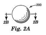
図2Aおよび2Bを参照すると、本発明のガス供給源の1つの実施形態が示される。気泡200は、平均厚さTおよび平均径Dを有する膜210を含む。1つ以上のガスがキャビティ220内に貯蔵される。
Referring to FIGS. 2A and 2B, one embodiment of the gas source of the present invention is shown.
気泡の所定の体積において補給のために利用可能なガスの量を最大にするために、ガスを高圧力において気泡内に貯蔵することができる。いくつかの実施形態において、貯蔵圧力は少なくとも約200kPa(29psi)(いくつかの実施形態において、少なくとも約1000kPa(145psi)、少なくとも約1725kPa(250psi)、またはさらに少なくとも約2750kPa(400psi))である。 In order to maximize the amount of gas available for replenishment in a given volume of bubbles, the gas can be stored in the bubbles at high pressure. In some embodiments, the storage pressure is at least about 200 kPa (29 psi) (in some embodiments, at least about 1000 kPa (145 psi), at least about 1725 kPa (250 psi), or even at least about 2750 kPa (400 psi)).
一般に、気泡は任意の形状、サイズ(例えば、平均径)、サイズ分布、体積、膜厚、密度、およびアスペクト比(球形気泡について平均径対平均壁厚さの比)であってもよい。 In general, the bubbles can be of any shape, size (eg, average diameter), size distribution, volume, film thickness, density, and aspect ratio (ratio of average diameter to average wall thickness for spherical bubbles).
気泡は任意の外形を有することができる。いくつかの実施形態において、気泡は最大の内部圧力に耐えるようにほぼ球形である。他の形状には、任意の数の面を有する任意の幾何学3次元多角形があり、例えば、立方体、円柱、半球、半円柱、角錐等がある。 The bubbles can have any outer shape. In some embodiments, the bubbles are substantially spherical to withstand maximum internal pressure. Other shapes include any geometric three-dimensional polygon having any number of faces, such as a cube, cylinder, hemisphere, half cylinder, pyramid, and the like.
いくつかの実施形態において、気泡は、サイズ(例えば、直径または体積)の分布を有することができる。いくつかの実施形態において、分布を粒度特性関数、例えば、ガウス、ローレンツ、または対数正規分布によって表すことができる。分布は単峰性(例えば、粒子の1つのサイズだけ)または多峰性(例えば、二峰性、三峰性など)でありうる。一般に、多峰性分布は、充填密度の増加をもたらす。 In some embodiments, the bubbles can have a size (eg, diameter or volume) distribution. In some embodiments, the distribution can be represented by a particle size characteristic function, such as a Gaussian, Lorentz, or lognormal distribution. The distribution can be unimodal (eg, only one size of particles) or multimodal (eg, bimodal, trimodal etc.). In general, a multimodal distribution results in an increase in packing density.
いくつかの実施形態において、気泡は、少なくとも約1マイクロメートル(μm)(いくつかの実施形態において、少なくとも約5μm、少なくとも約10μm、またはさらに少なくとも約20μm)の中位径(すなわち、第50百分位数)を有することができる。いくつかの実施形態において、気泡は、約5000μm未満(いくつかの実施形態において、約1000μm未満、約500μm未満、約100μm未満、またはさらに約50μm未満)の平均サイズを有することができる。いくつかの実施形態において、気泡は、気泡1個あたりの平均内部体積が少なくとも約50立方マイクロメートル(いくつかの実施形態において、少なくとも約250立方マイクロメートル、またはさらに少なくとも約500立方マイクロメートル)である。いくつかの実施形態において、気泡は、約10億立方マイクロメートル(いくつかの実施形態において、約2億5000万立方マイクロメートル未満、または5000万立方マイクロメートル未満、またはさらに500万立方マイクロメートル未満)の平均体積を有する。 In some embodiments, the bubble is at least about 1 micrometer (μm) (in some embodiments, at least about 5 μm, at least about 10 μm, or even at least about 20 μm) median diameter (ie, Quantile). In some embodiments, the bubbles can have an average size of less than about 5000 μm (in some embodiments, less than about 1000 μm, less than about 500 μm, less than about 100 μm, or even less than about 50 μm). In some embodiments, the bubbles have an average internal volume per bubble of at least about 50 cubic micrometers (in some embodiments, at least about 250 cubic micrometers, or even at least about 500 cubic micrometers). is there. In some embodiments, the bubbles are about 1 billion cubic micrometers (in some embodiments, less than about 250 million cubic micrometers, or less than 50 million cubic micrometers, or even less than 5 million cubic micrometers). ) Average volume.
一般に、膜210は、使用条件(例えば、温度)において気泡内に貯蔵されたガスに対して透過性である場合、任意の材料を含んでもよい。例示的な膜には、ガラス、ガラス/セラミック、金属(例えば、TiおよびPd)、金属酸化物の他、金属および金属酸化物の多層、他の金属化合物、例えば窒化物、炭化物、およびケイ化物、合金、およびポリマー材料などがある。いくつかの実施形態において、膜は、同一または異なった材料の複数の層を含む。膜のために使用される材料の選択は、例えば、透過性(すなわち、膜を通しての、貯蔵されたガスの輸送速度)、密度、および機械的性質(例えば、引張強さ、圧縮抵抗)に左右される場合がある。
In general, the
一般に、特定の膜材料を通してのガスの透過性を通例の実験によって測定することができる。(例えば、ASTM試験方法D737−96およびD3985を参照のこと)。また、透過速度は、文献に記載されている。(例えば、Vacuum Technology、ロス,A.(Roth,A.)著、ノース・ホランド・パブリッシング・カンパニー(North Holland Publishing Co.)、164頁および166頁(1976年)を参照のこと)。一般に、透過性は、例えば、膜の組成、各層の厚さ、および層の1つ以上においてのピンホール、ボイド、またはパターンの存在に左右される場合がある。 In general, gas permeability through a particular membrane material can be measured by routine experimentation. (See, eg, ASTM test methods D737-96 and D3985). Further, the transmission speed is described in the literature. (See, for example, Vacuum Technology, Ross, A. (Roth, A.), North Holland Publishing Co., pages 164 and 166 (1976)). In general, permeability may depend, for example, on the composition of the membrane, the thickness of each layer, and the presence of pinholes, voids, or patterns in one or more of the layers.
いくつかの実施形態において、膜の平均厚さは少なくとも0.01μmである(いくつかの実施形態において、少なくとも0.1μm、またはさらに少なくとも0.5μmである)。いくつかの実施形態において、膜の平均厚さは20μm未満である(いくつかの実施形態において、5.0μm未満、またはさらに2.0μm未満である)。いくつかの実施形態において、気泡は、膜厚の分布を有することができる。いくつかの実施形態において、膜厚の分布を調節することによって複数の気泡の平均透過速度を制御することができる。 In some embodiments, the average thickness of the membrane is at least 0.01 μm (in some embodiments, at least 0.1 μm, or even at least 0.5 μm). In some embodiments, the average thickness of the film is less than 20 μm (in some embodiments, less than 5.0 μm, or even less than 2.0 μm). In some embodiments, the bubbles can have a film thickness distribution. In some embodiments, the average permeation rate of the plurality of bubbles can be controlled by adjusting the film thickness distribution.
ガラス気泡は任意の公知の方法によって作製されてもよい。(例えば、米国特許第3,365,315号明細書および米国特許第4,767,726号明細書を参照のこと)。さらに、本発明において有用なガラス気泡は市販されており、例えば、ミネソタ州、セントポールの3Mカンパニー(3M Company,St.Paul,Minnesota)から商品名スコッチライト・ガラス・バブル(Scotchlite Glass Bubbles)として入手可能なガラス気泡が挙げられる。また、セラミック気泡も市販されており、例えば、3Mカンパニーから商品名Z−ライト・スフェア(Z−Light Spheres)およびゼーオスフェア(Zeeospheres)として入手可能なセラミック気泡が挙げられる。 Glass bubbles may be produced by any known method. (See, for example, US Pat. No. 3,365,315 and US Pat. No. 4,767,726). Further, glass bubbles useful in the present invention are commercially available, for example, as the Scotchlite Glass Bubbles from 3M Company, St. Paul, Minnesota (3M Company, St. Paul, Minnesota). Examples include available glass bubbles. Ceramic bubbles are also commercially available, such as those available from 3M Company under the trade names Z-Light Spheres and Zeosspheres.
いくつかの実施形態において、膜の透過性は、膜の性質を変えることによって調節されてもよい。一般に、膜厚または密度の増加は、透過性を減少させる。また、1つ以上の層を膜の表面に適用して透過性を低減してもよい。例えば、無機材料(例えば、金属および/または金属酸化物)をガラスまたはガラスセラミック膜に適用してもよい。いくつかの実施形態において、金、銀、銅、スズ、亜鉛、アルミニウム、タングステン、クロム、ジルコニウム、チタン、ニッケル、パラジウムおよび/または白金などの金属を用いてもよい。他の有用な材料には、炭素およびケイ素、および金属および/またはメタロイドを含有する合金などがある。いくつかの実施形態において、窒化チタン、酸化スズ、または酸化アルミニウムを用いてもよい。 In some embodiments, the permeability of the membrane may be adjusted by changing the properties of the membrane. In general, increasing film thickness or density decreases permeability. One or more layers may also be applied to the membrane surface to reduce permeability. For example, an inorganic material (eg, metal and / or metal oxide) may be applied to the glass or glass ceramic membrane. In some embodiments, metals such as gold, silver, copper, tin, zinc, aluminum, tungsten, chromium, zirconium, titanium, nickel, palladium and / or platinum may be used. Other useful materials include carbon and silicon, and alloys containing metals and / or metalloids. In some embodiments, titanium nitride, tin oxide, or aluminum oxide may be used.
いくつかの実施形態において、層の厚さは少なくとも約0.2ナノメートル(nm)である(いくつかの実施形態において、少なくとも約0.3nm、少なくとも約0.5nm、またはさらに少なくとも約1nmである)。いくつかの実施形態において、層の厚さは約20nm未満である(いくつかの実施形態において、約10nm未満、または約5nm未満、またはさらに約2nm未満である)。 In some embodiments, the layer thickness is at least about 0.2 nanometers (nm) (in some embodiments, at least about 0.3 nm, at least about 0.5 nm, or even at least about 1 nm. is there). In some embodiments, the layer thickness is less than about 20 nm (in some embodiments, less than about 10 nm, or less than about 5 nm, or even less than about 2 nm).
いくつかの実施形態において、ボイドまたはピンホールが1つ以上の層に存在してもよい。いくつかの実施形態において、層の1つ以上が膜の一部だけに適用されてもよい。いくつかの実施形態において、気泡の一部だけが、膜に適用された付加的な層を有する。一般に、これらの性質の各々を調節して複数の気泡の平均透過速度を制御してもよい。 In some embodiments, voids or pinholes may be present in one or more layers. In some embodiments, one or more of the layers may be applied to only a portion of the membrane. In some embodiments, only a portion of the bubbles have an additional layer applied to the membrane. In general, each of these properties may be adjusted to control the average permeation rate of the plurality of bubbles.
例えば、物理蒸着(スパッタコーティング、蒸発コーティング、およびカソードアーク堆積)、化学蒸着、無電解めっきの他、ゾル−ゲルコーティングなどの湿式化学手段など、任意の公知の方法を用いて無機材料の薄いフィルムをガラス気泡に適用してもよい(例えば、米国特許第4,618,525号明細書を参照のこと)。市販のコーティングされたガラス気泡には、例えば、ペンシルベニア州、バレーフォージのポッターズ・インダストリーズ社(Potters Industries,Inc.,Valley Forge,Pennsylvania)から商品名コンダクト・O・フィル(Conduct−O−Fill)として入手可能なガラスバブルがある。 Thin films of inorganic materials using any known method such as physical vapor deposition (sputter coating, evaporation coating, and cathodic arc deposition), chemical vapor deposition, electroless plating, and wet chemical means such as sol-gel coating May be applied to glass bubbles (see, eg, US Pat. No. 4,618,525). Commercially coated glass bubbles include, for example, the product name Conduct-O-Fill from Potters Industries, Inc., Valley Forge, Pennsylvania, Pennsylvania. There is a glass bubble available as
いくつかの実施形態において、気泡の表面を、例えば、有機材料、例えば、エポキシシランおよびメタクリル酸塩化第二クロムで処理してもよい。例示的な表面処理された気泡には、3Mカンパニーから商品名スコッチライト・ガラス・バブル(例えば、D32/4500、H20/1000、およびA20/1000)として入手可能な気泡がある。 In some embodiments, the cell surface may be treated with, for example, organic materials such as epoxy silane and chromic methacrylate. Exemplary surface treated bubbles include those available from 3M Company under the trade name Scotchlite Glass Bubble (eg, D32 / 4500, H20 / 1000, and A20 / 1000).
ガス供給源は、任意の公知の手段によって筺体に組み込まれてもよい。いくつかの実施形態において、気泡は筺体内に緩く置かれてもよい。いくつかの実施形態において、気泡は、透過性容器、例えば、ポリマー袋またはパウチ内に置かれてもよく、パウチが筺体内に置かれる。いくつかの実施形態において、ポリマーパウチを例えば金属または金属酸化物でコーティングして、パウチの壁を通しての不活性ガスの透過度を制御することができる。 The gas supply source may be incorporated into the housing by any known means. In some embodiments, the bubble may be loosely placed in the enclosure. In some embodiments, the air bubbles may be placed in a permeable container, such as a polymer bag or pouch, where the pouch is placed in the enclosure. In some embodiments, the polymer pouch can be coated with, for example, a metal or metal oxide to control the permeability of the inert gas through the wall of the pouch.
いくつかの実施形態において、気泡に樹脂を混入してもよい。いくつかの実施形態において、気泡を樹脂の表面に付着させてもよく、および/または樹脂に部分的に封入してもよい。いくつかの実施形態において、気泡の一部を樹脂に完全に封入してもよい。いくつかの実施形態において、気泡のほぼすべて(例えば、90重量%超、いくつかの実施形態において、95%超、またはさらに99%超)を樹脂に完全に封入してもよい。 In some embodiments, a resin may be mixed into the bubbles. In some embodiments, bubbles may be attached to the surface of the resin and / or partially encapsulated in the resin. In some embodiments, some of the bubbles may be completely encapsulated in the resin. In some embodiments, substantially all of the bubbles (eg, greater than 90% by weight, in some embodiments, greater than 95%, or even greater than 99%) may be completely encapsulated in the resin.
一般に、任意の公知の樹脂を用いてもよい。いくつかの実施形態において、樹脂は、気泡の内部から樹脂を通して筺体の内部へのガスの透過度を制御するために選択されてもよい。例示的な樹脂には、アクリレート、メタクリレート、エポキシ、シリコーン、オレフィン、およびポリエステルなどがある。樹脂は、熱可塑性、熱硬化性、エラストマー、または熱可塑性エラストマーであってもよい。いくつかの実施形態において、高度に架橋された樹脂(例えば、エポキシ)を用いてもよい。いくつかの実施形態において、高結晶性樹脂(例えば、ポリエチレンおよびエチレンビニルアルコール)を用いてもよい。樹脂は、例えば、湿分、熱、化学線(例えば、可視光線、紫外線)、または電子ビームによって硬化可能である場合がある。 In general, any known resin may be used. In some embodiments, the resin may be selected to control gas permeability from the interior of the bubble through the resin to the interior of the enclosure. Exemplary resins include acrylates, methacrylates, epoxies, silicones, olefins, and polyesters. The resin may be a thermoplastic, thermosetting, elastomer, or thermoplastic elastomer. In some embodiments, a highly crosslinked resin (eg, epoxy) may be used. In some embodiments, highly crystalline resins (eg, polyethylene and ethylene vinyl alcohol) may be used. The resin may be curable by, for example, moisture, heat, actinic radiation (eg, visible light, ultraviolet light), or electron beam.
気泡は、任意の公知の手段、例えば、溶融樹脂または樹脂の溶液(例えば、水溶液または溶剤溶液)中に気泡を混合することによって樹脂に混入されてもよい。いくつかの実施形態において、気泡は、例えば、二本ロール機を用いて樹脂とロール練りされてもよい。いくつかの実施形態において、気泡を押出機に添加して樹脂と配合してもよい。いくつかの実施形態において、気泡をプレポリマー混合物に添加してもよく、次いで重合して樹脂を形成する。 The bubbles may be mixed into the resin by any known means, for example, by mixing the bubbles in a molten resin or resin solution (eg, an aqueous solution or solvent solution). In some embodiments, the bubbles may be roll kneaded with resin using, for example, a two roll machine. In some embodiments, bubbles may be added to the extruder and blended with the resin. In some embodiments, bubbles may be added to the prepolymer mixture and then polymerized to form a resin.
いくつかの実施形態において、樹脂は接着剤であってもよい。いくつかの実施形態において、気泡の充填された接着剤を用いて筺体内の部品を接合してもよく、および/または筺体のセクションを接合してもよい。いくつかの実施形態において、樹脂を用いて、筺体と共に用いられた(例えば、筺体のセクションの間に配置された)ガスケットを形成してもよい。いくつかの実施形態において、気泡含有樹脂を筺体の1つ以上の内側表面上に適用してもよい(例えば、コーティングしてもよい)。いくつかの実施形態において、樹脂を筺体内の成分の1つ以上の表面に適用してもよい。 In some embodiments, the resin may be an adhesive. In some embodiments, bubble-filled adhesive may be used to join the parts within the enclosure and / or the sections of the enclosure. In some embodiments, a resin may be used to form a gasket used with the housing (eg, disposed between sections of the housing). In some embodiments, the cell-containing resin may be applied (eg, coated) on one or more inner surfaces of the housing. In some embodiments, the resin may be applied to one or more surfaces of the components within the enclosure.
気泡の他に、樹脂は、例えば、シリカ、タルク、カーボンブラック、導電性および/または熱伝導性粒子、レオロジー改良剤(例えば、チキソトロープ剤)、粘着剤、可塑剤、発泡剤、繊維、中実および/または中空ビード、染料、および/または顔料などの他の材料を含有してもよい。 In addition to foam, the resin can be, for example, silica, talc, carbon black, conductive and / or thermally conductive particles, rheology modifiers (eg thixotropic agents), adhesives, plasticizers, foaming agents, fibers, solids. And / or other materials such as hollow beads, dyes, and / or pigments.
いくつかの実施形態において、ガスは透過性容器、例えば、パウチに貯蔵されてもよく、パウチは筺体内に配置されてもよい。パウチは、コーティングされたまたはコーティングされていないポリマーフィルムを含んでもよい。コーティングには、有機および無機(例えば、金属および/または金属酸化物)材料がある。 In some embodiments, the gas may be stored in a permeable container, such as a pouch, and the pouch may be placed in a housing. The pouch may comprise a coated or uncoated polymer film. Coatings include organic and inorganic (eg, metal and / or metal oxide) materials.
透過性膜中に含有された所望のガスを含むガス供給源によって提供された補給速度は、例えば、膜の平均透過性、透過性膜中に含有された所望のガスの全体積、筺体中の所望のガスの分圧、もしあるならば、ガス含有透過性膜を密閉する樹脂、および筺体内の温度および圧力などの様々なパラメーターの関数である。一般に、補給速度は、所望のガスが透過性膜を通して拡散する時に経時的に変化することがある。 The replenishment rate provided by the gas source containing the desired gas contained in the permeable membrane is, for example, the average permeability of the membrane, the total volume of the desired gas contained in the permeable membrane, in the enclosure It is a function of various parameters such as the partial pressure of the desired gas, if any, the resin sealing the gas-containing permeable membrane, and the temperature and pressure within the enclosure. In general, the replenishment rate may change over time as the desired gas diffuses through the permeable membrane.
いくつかの実施形態において、筺体内の所望のガスの消耗を実質的に防ぐのに十分な補給速度を有するガス供給源を提供することが望ましいことがあり、すなわち、補給速度は、例えば、反応、漏れおよび/または拡散によって所望のガスが筺体から除去される速度の合計以上であるのがよい。 In some embodiments, it may be desirable to provide a gas source that has a replenishment rate sufficient to substantially prevent depletion of the desired gas within the enclosure, i.e., the replenishment rate is, for example, reaction It should be greater than or equal to the total rate at which the desired gas is removed from the enclosure by leakage and / or diffusion.
いくつかの実施形態において、筺体内の所望のガスの相対量(例えば、分圧)をその初期相対量に対して所望のレベルに維持するのに十分な補給速度を有するガス供給源を提供することが望ましい場合がある。いくつかの実施形態において、補給速度は、筺体内の所望のガスの分圧をその初期分圧の少なくとも20%、いくつかの実施形態においてその初期分圧の少なくとも50%、いくつかの実施形態において、少なくとも75%、またはさらに少なくとも90%に維持するために十分であるのがよい。 In some embodiments, a gas source is provided having a replenishment rate sufficient to maintain a relative amount (eg, partial pressure) of a desired gas within the enclosure at a desired level relative to its initial relative amount. Sometimes it is desirable. In some embodiments, the replenishment rate is such that the partial pressure of the desired gas in the enclosure is at least 20% of its initial partial pressure, in some embodiments at least 50% of its initial partial pressure, in some embodiments. In order to maintain at least 75%, or even at least 90%.
いくつかの実施形態において、筺体内の所望のガスの分圧は、筺体内のコンポーネントの可使時間の間、維持されるべきである。いくつかの実施形態において、筺体内の所望のガスの分圧は、少なくとも1年間、いくつかの実施形態において、少なくとも2年間、いくつかの実施形態において、少なくとも3年間、さらに少なくとも5年間、またはさらにそれ以上、維持されるべきである。 In some embodiments, the desired partial pressure of gas within the enclosure should be maintained during the pot life of the components within the enclosure. In some embodiments, the partial pressure of the desired gas within the enclosure is at least 1 year, in some embodiments, at least 2 years, in some embodiments, at least 3 years, and at least 5 years, or Further, it should be maintained.
以下の特定の、しかし非限定的な実施例が本発明を説明するために役立つ。すべてのパーセンテージは、特に記載しない限り、重量に基づいている。 The following specific but non-limiting examples serve to illustrate the invention. All percentages are based on weight unless otherwise stated.
コーティングされていない気泡
3Mカンパニーから商品名スコッチライト・ガラス・バブルS60/10,000として入手可能な気泡を用いた。該ガラスは、70〜80% SiO2、8〜15% CaO、3〜8% Na2O、および2〜6% B2O3であると報告されている。平均気泡密度は0.60±0.02g/cc、中位径(すなわち、第50百分位数)30マイクロメートル、平均壁厚さ1.3マイクロメートル、および内径28マイクロメートルであると報告されている。
Uncoated bubbles Bubbles available from 3M Company under the trade name Scotchlite Glass Bubble S60 / 10,000 were used. The glass, 70~80% SiO 2, 8~15% CaO, has been reported to be 3~8% Na 2 O, and 2~6% B 2 O 3. Reported average bubble density of 0.60 ± 0.02 g / cc, median diameter (ie 50th percentile) 30 micrometers, average wall thickness 1.3 micrometers, and internal diameter 28 micrometers Has been.
アルミニウムのコーティングされた気泡
コーティングされていない気泡の試料をアルミニウムの薄い(約1000オングストローム)層でコーティングした。気泡は、スパッタリング源から金属原子のフラックスでコーティングされる間、撹拌された。次に、酸化アルミニウムのフィルムを、アルミニウムスパッタリングの間、酸素の同時添加を必要とする反応性スパッタ堆積によってアルミニウム層上に堆積した。コーティングされた気泡の密度は0.65g/cm3であった。
Aluminum Coated Bubbles A sample of uncoated bubbles was coated with a thin (about 1000 angstrom) layer of aluminum. The bubbles were agitated while being coated with a flux of metal atoms from a sputtering source. Next, a film of aluminum oxide was deposited on the aluminum layer by reactive sputter deposition requiring simultaneous addition of oxygen during aluminum sputtering. The density of the coated bubbles was 0.65 g / cm 3 .
ガスの充填
コーティングされていないおよびアルミニウムのコーティングされた気泡の両方が充填された。以下の実施例において、コーティングされた気泡は、コーティングが適用された後に充填された。一般に、気泡は、1つ以上のコーティングが適用される前または後のどちらにガスで充填されてもよい。
Gas Filling Both uncoated and aluminum coated bubbles were filled. In the following examples, the coated bubbles were filled after the coating was applied. In general, the bubbles may be filled with a gas either before or after one or more coatings are applied.
約70グラムの気泡をオートクレーブに装填し、次いでそれを封止し、空気を排気した。オートクレーブをヘリウムガスで6.9メガパスカル(MPa)(1000ポンド/平方インチ(psi))に加圧し、300℃に加熱した。温度が300℃に達すると、ヘリウムガスの圧力を6.9MPa(1000psi)の増分で増し、1時間、各増分に保持した。48MPa(7000psi)の圧力に達したとき、系を3時間、一定に保持した。次いで、オートクレーブを冷却し、脱気し、気泡をオートクレーブから取り出した。 About 70 grams of air bubbles were loaded into the autoclave, which was then sealed and the air was evacuated. The autoclave was pressurized with helium gas to 6.9 megapascals (MPa) (1000 pounds per square inch (psi)) and heated to 300 ° C. When the temperature reached 300 ° C., the helium gas pressure was increased in increments of 6.9 MPa (1000 psi) and held at each increment for 1 hour. When a pressure of 48 MPa (7000 psi) was reached, the system was held constant for 3 hours. The autoclave was then cooled and degassed and air bubbles were removed from the autoclave.
気泡内のガスの圧力の推定値を理想気体の法則(すなわち、P1/T1=P2/T2)を用いて計算することができる。従って、P1=48MPa、T1=573K(300℃)およびT2=298K(25℃)によって、周囲温度における気泡内の圧力P2を計算すると25MPa(3640psi)である。 An estimate of the pressure of the gas in the bubble can be calculated using the ideal gas law (ie, P 1 / T 1 = P 2 / T 2 ). Therefore, P 1 = 48MPa, the T 1 = 573K (300 ℃) and T 2 = 298K (25 ℃) , it is when calculating the pressure P 2 in the gas bubbles at ambient temperature 25MPa (3640psi).
気泡の透過性
気泡膜を通して透過によってガラス気泡から放出されたガス量をガスクロマトグラフィーを用いて測定した。コーティングされたおよびコーティングされていない気泡の両方を周囲温度および高温において試験した。試験の前にヘリウムの損失を最小にするために、すべての気泡を、試験のために選択されるまでオートクレーブから取り出された後、-20℃において貯蔵した。試料の概要を表1に示す。
Bubble permeability The amount of gas released from the glass bubbles by permeation through the bubble membrane was measured using gas chromatography. Both coated and uncoated bubbles were tested at ambient and elevated temperatures. To minimize helium loss prior to testing, all bubbles were stored at -20 ° C. after being removed from the autoclave until selected for testing. A summary of the sample is shown in Table 1.

各々の実施例について、気泡を2.54cm×2.54cm(1インチ×1インチ)のプラスチック秤量ボート中に秤量し、次いでそれを周囲空気を含有する閉じ込め管(containment tube)中に置いた。閉じ込め管の体積は約600mLであった。管の接合部を高真空グリースで封止した。実施例1および3を周囲温度(21℃)に保持し、実施例2および4を70℃の炉内に置いた。 For each example, the air bubble was weighed into a 2.54 cm x 2.54 cm (1 inch x 1 inch) plastic weighing boat, which was then placed in a containment tube containing ambient air. The volume of the confinement tube was about 600 mL. The joint of the tube was sealed with high vacuum grease. Examples 1 and 3 were held at ambient temperature (21 ° C.) and Examples 2 and 4 were placed in a 70 ° C. oven.
ガスクロマトグラフィー(GC)を用いて閉じ込め管内の雰囲気の組成の変化をモニタした。定期的に、閉じ込め管内の雰囲気を少しずつ除去し、試料容器内に貯蔵した。試料抽出する前に、高温に保持された管を炉から取り出し、約30分間、室温に冷却させた。各々の試料容器をコーンおよびソケット継手によってガスクロマトグラフの試料抽出孔に接続した。GC分析のための運転パラメーターを表2に示す。気泡1グラム当たり気泡から透過したガスの体積を表3および4に示す。 Gas chromatography (GC) was used to monitor changes in the composition of the atmosphere in the confinement tube. Periodically, the atmosphere in the confinement tube was removed little by little and stored in a sample container. Prior to sample extraction, the hot tube was removed from the furnace and allowed to cool to room temperature for approximately 30 minutes. Each sample container was connected to the sample extraction hole of the gas chromatograph by a cone and socket joint. Table 2 shows the operating parameters for the GC analysis. The volume of gas permeated from the bubbles per gram of bubbles is shown in Tables 3 and 4.
気泡内のガスの実体積
方法1:ガスクロマトグラフィー
ヘリウムの充填された、コーティングされていない気泡の試料を上述のように閉じ込め管内に置いた。閉じ込め管および気泡を1週間、150℃の炉内に置いた。次いで該管を炉から取り出し、室温に冷却させ、上述のように、該管内の雰囲気をGCを用いて分析した。気泡は、気泡1グラム当たりヘリウム250mLを含有することがわかった。
Real Volume of Gas in Bubble Method 1: Gas Chromatography A sample of uncoated bubble filled with helium was placed in a containment tube as described above. The containment tube and bubbles were placed in a 150 ° C. oven for 1 week. The tube was then removed from the furnace, allowed to cool to room temperature, and the atmosphere in the tube was analyzed using GC as described above. The bubbles were found to contain 250 mL of helium per gram of bubbles.
同様に、ヘリウムの充填された、コーティングされていない気泡の試料を閉じ込め管内に置き、10分間600℃の炉内に置いた。次いで該管を炉から取り出し、室温に冷却させ、上述のように、該管内の雰囲気をGCを用いて分析した。気泡は、気泡1グラム当たりヘリウム191mLを含有する。 Similarly, a sample of uncoated bubble filled with helium was placed in a containment tube and placed in a 600 ° C. oven for 10 minutes. The tube was then removed from the furnace, allowed to cool to room temperature, and the atmosphere in the tube was analyzed using GC as described above. The bubbles contain 191 mL of helium per gram of bubbles.
方法2:等方圧圧潰試験
気泡内に含有されたヘリウムの量を測定するために、0.364グラム(g)の気泡を、3.5gのグリセロール(EM・サイエンス・コーポレーション(EM Science Corp.)から得られた分析銘柄グリセロール)を含有するバルーン(ナショナル・ラテックス・プロダクト(National Latex Products)から得られた番号1032ラテックスバルーン)中に置いた。気泡およびグリセロールで充填されたバルーンの初期体積を測定するために、メスシリンダーに含有された10W−30エンジン油に浸漬した。次に、バルーンおよびその内容物に十分な等方圧(isostactic pressure)(138MPa(20,000psi))を加えて気泡を壊し、内部に貯蔵されたヘリウムを放出した。バルーンの体積の増加を測定するために、メスシリンダー中の油の排除量を測定した。
Method 2: Isotropic Crush Test To determine the amount of helium contained in the bubbles, 0.364 grams (g) of bubbles was added to 3.5 g of glycerol (EM Science Corp.). ) (Analytical grade glycerol obtained from)) (No. 1032 latex balloon obtained from National Latex Products). To measure the initial volume of bubbles and balloon filled with glycerol, it was immersed in 10W-30 engine oil contained in a graduated cylinder. Next, sufficient isostatic pressure (138 MPa (20,000 psi)) was applied to the balloon and its contents to break the bubbles and release the helium stored therein. To measure the increase in balloon volume, the amount of oil excluded in the graduated cylinder was measured.
ヘリウムの充填されたガラス気泡の2つの試料を試験した。オートクレーブから取り出された後1時間以内に試験された第1の試料は、0.417gの試料中に18mLのヘリウムを含有した(43.2mL/g)。この体積に基づいて、充填された気泡内の圧力を計算すると2.74MPa(397psi)であった。オートクレーブから取り出された24時間後に試験された第2の試料は、0.364gの試料中に8mLのヘリウムを含有した(22.0mL/g)。充填された気泡内の圧力を計算すると1.76MPa(255psi)であった。 Two samples of glass bubbles filled with helium were tested. The first sample tested within 1 hour after removal from the autoclave contained 18 mL of helium in a 0.417 g sample (43.2 mL / g). Based on this volume, the pressure in the filled bubbles was calculated to be 2.74 MPa (397 psi). A second sample tested 24 hours after removal from the autoclave contained 8 mL of helium in a 0.364 g sample (22.0 mL / g). The pressure inside the filled bubbles was calculated to be 1.76 MPa (255 psi).
本発明の様々な改良および変更が本発明の範囲および精神から逸脱せずに実施できることは、当業者には明らかである。 It will be apparent to those skilled in the art that various modifications and variations can be made in the present invention without departing from the scope or spirit of the invention.
Claims (22)
(a)膜厚の分布、
(b)直径の分布、または
(c)それらの組合せを有する、請求項1に記載の筺体。 The gas supply source has a plurality of bubbles, and optionally, the plurality of bubbles are:
(A) Film thickness distribution,
The enclosure of claim 1 having (b) a distribution of diameters, or (c) a combination thereof.
Applications Claiming Priority (2)
| Application Number | Priority Date | Filing Date | Title |
|---|---|---|---|
| US57437004P | 2004-05-25 | 2004-05-25 | |
| PCT/US2005/016153 WO2005117018A2 (en) | 2004-05-25 | 2005-05-10 | Internally replenished enclosure |
Publications (2)
| Publication Number | Publication Date |
|---|---|
| JP2008500677A true JP2008500677A (en) | 2008-01-10 |
| JP2008500677A5 JP2008500677A5 (en) | 2008-06-26 |
Family
ID=34970470
Family Applications (1)
| Application Number | Title | Priority Date | Filing Date |
|---|---|---|---|
| JP2007515130A Pending JP2008500677A (en) | 2004-05-25 | 2005-05-10 | Internally supplied housing |
Country Status (8)
| Country | Link |
|---|---|
| US (2) | US7538972B2 (en) |
| EP (1) | EP1756831B1 (en) |
| JP (1) | JP2008500677A (en) |
| CN (1) | CN1961375B (en) |
| AT (1) | ATE378680T1 (en) |
| DE (1) | DE602005003359T2 (en) |
| TW (1) | TW200617896A (en) |
| WO (1) | WO2005117018A2 (en) |
Families Citing this family (34)
| Publication number | Priority date | Publication date | Assignee | Title |
|---|---|---|---|---|
| US7365937B2 (en) * | 2003-07-24 | 2008-04-29 | Seagate Technology Llc | Inert gas atmosphere replenishment structure |
| DE102005041863A1 (en) * | 2005-09-02 | 2007-03-29 | Ashland-Südchemie-Kernfest GmbH | Borosilicate glass-containing molding material mixtures |
| US7961427B2 (en) * | 2007-05-22 | 2011-06-14 | Galleon International Corporation | High performance computer hard disk drive with a carbon overcoat and method of improving hard disk performance |
| US8014167B2 (en) * | 2007-09-07 | 2011-09-06 | Seagate Technology Llc | Liquid crystal material sealed housing |
| US8094409B2 (en) | 2008-05-28 | 2012-01-10 | Hitachi Global Storage Technologies, Netherlands B.V. | Method and system for monitoring gas in sealed hard disk drives with feedback |
| US8999245B2 (en) * | 2009-07-07 | 2015-04-07 | Tricorn Tech Corporation | Cascaded gas chromatographs (CGCs) with individual temperature control and gas analysis systems using same |
| US8707760B2 (en) | 2009-07-31 | 2014-04-29 | Tricorntech Corporation | Gas collection and analysis system with front-end and back-end pre-concentrators and moisture removal |
| US8978444B2 (en) | 2010-04-23 | 2015-03-17 | Tricorn Tech Corporation | Gas analyte spectrum sharpening and separation with multi-dimensional micro-GC for gas chromatography analysis |
| US20110312858A1 (en) * | 2010-06-21 | 2011-12-22 | Holt Jonathan W | Composition and methods for oilfield application |
| US8279552B2 (en) * | 2010-06-22 | 2012-10-02 | Hitachi Global Storage Technologies, Netherlands B.V. | Hermetically sealing a hard disk drive |
| US8934194B2 (en) * | 2011-01-09 | 2015-01-13 | Erhard Schreck | System and method for maintaining a low density gas environment in a disk drive |
| US9190115B2 (en) | 2011-04-28 | 2015-11-17 | Entrotech, Inc. | Method of assembling a disk drive |
| US8599514B2 (en) | 2011-04-28 | 2013-12-03 | Entrotech, Inc. | Stabilization of components within hard disk drives and related methods |
| US8837080B2 (en) | 2011-04-28 | 2014-09-16 | Entrotech, Inc. | Hard disk drives with composite housings and related methods |
| US9466335B2 (en) | 2011-04-28 | 2016-10-11 | Entrotech, Inc. | Hermetic hard disk drives comprising integrally molded filters and related methods |
| US8760797B1 (en) | 2013-06-13 | 2014-06-24 | Seagate Technology Llc | Contamination control for a disc drive |
| US20150294691A1 (en) * | 2014-04-09 | 2015-10-15 | HGST Netherlands B.V. | Sealed disk media enclosure |
| EP3134898A4 (en) | 2014-04-22 | 2017-12-13 | Entrotech, Inc. | Re-workable sealed hard disk drives, cover seals therefor, and related methods |
| EP3152757A1 (en) | 2014-06-09 | 2017-04-12 | Entrotech, Inc. | Laminate-wrapped hard disk drives and related methods |
| US9601161B2 (en) | 2015-04-15 | 2017-03-21 | entroteech, inc. | Metallically sealed, wrapped hard disk drives and related methods |
| US9721620B2 (en) | 2015-12-09 | 2017-08-01 | Western Digital Technologies, Inc. | Hermetic sealing of hard disk drive using laminated film seal |
| US9721619B2 (en) | 2015-12-09 | 2017-08-01 | Western Digital Technologies, Inc. | Hermetic sealing of hard disk drive using laminated film seal |
| US9704539B2 (en) | 2015-12-09 | 2017-07-11 | Western Digital Technologies, Inc. | Hermetic sealing of hard disk drive using laminated film seal |
| US9570114B1 (en) | 2016-01-15 | 2017-02-14 | HGST Netherlands B.V. | Laminated film-packed hard disk drive for hermetic sealing |
| US9916872B1 (en) * | 2016-12-20 | 2018-03-13 | Western Digital Technologies, Inc. | Double-barrier vacuum seal for sealed data storage system |
| US10262698B2 (en) | 2017-06-21 | 2019-04-16 | Western Digital Technologies, Inc. | Intermittent operation of compartmented pneumatics for sealed data storage system |
| US10971195B2 (en) * | 2018-08-23 | 2021-04-06 | Seagate Technology Llc | Cavity seal and moisture control |
| US10706893B1 (en) * | 2019-07-31 | 2020-07-07 | Seagate Technology Llc | Method of temporarily sealing data storage device and device |
| US11783867B2 (en) | 2019-08-07 | 2023-10-10 | Seagate Technology Llc | Electronic device that includes a composition that can actively generate and release a gaseous oxidizing agent component into an interior space of the electronic device, and related subassemblies and methods |
| US11763853B2 (en) | 2019-08-07 | 2023-09-19 | Seagate Technology Llc | Electronic device that includes a composition that can actively generate and release a gaseous oxidizing agent component into an interior space of the electronic device, and related subassemblies and methods |
| US11024343B2 (en) | 2019-08-07 | 2021-06-01 | Seagate Technology Llc | Electronic device that includes a composition that can actively generate and release a gaseous oxidizing agent component into an interior space of the electronic device, and related subassemblies and methods |
| CN114556474A (en) * | 2019-08-22 | 2022-05-27 | 唐纳森公司 | Gas supplement component for housing |
| US11348619B2 (en) | 2020-07-16 | 2022-05-31 | Western Digital Technologies, Inc. | Dual gasket for manufacturing of hermetically-sealed hard disk drive |
| US11270739B1 (en) * | 2021-02-09 | 2022-03-08 | Seagate Technology Llc | Electronic device that includes one or more reactants that generate a gaseous oxidizing agent component inside the electronic device, and related subassemblies and methods |
Citations (5)
| Publication number | Priority date | Publication date | Assignee | Title |
|---|---|---|---|---|
| JPS59213633A (en) * | 1983-05-13 | 1984-12-03 | グラヴルベル | Gas-filled glass bead |
| JPS63176338A (en) * | 1987-01-12 | 1988-07-20 | ミネソタ マイニング アンド マニユフアクチユアリング カンパニー | Microbubble |
| JPH0785647A (en) * | 1993-09-20 | 1995-03-31 | Hitachi Ltd | Magnetic disk and magnetic disk device |
| JP2515312B2 (en) * | 1985-06-03 | 1996-07-10 | ミネソタ マイニング アンド マニユフアクチユアリング カンパニ− | Glass microfoam and cohesive articles |
| WO2003041081A1 (en) * | 2001-11-02 | 2003-05-15 | Seagate Technology Llc | Internal disc drive gas reservoir |
Family Cites Families (20)
| Publication number | Priority date | Publication date | Assignee | Title |
|---|---|---|---|---|
| US2797201A (en) | 1953-05-11 | 1957-06-25 | Standard Oil Co | Process of producing hollow particles and resulting product |
| US2892508A (en) | 1957-04-17 | 1959-06-30 | Bell Telephone Labor Inc | Separation of gases by diffusion |
| NL232500A (en) | 1957-10-22 | |||
| US3184899A (en) | 1958-12-31 | 1965-05-25 | Standard Oil Co | Helium separation |
| US3365315A (en) | 1963-08-23 | 1968-01-23 | Minnesota Mining & Mfg | Glass bubbles prepared by reheating solid glass partiles |
| US4211537A (en) * | 1978-07-24 | 1980-07-08 | Teitel Robert J | Hydrogen supply method |
| US4367503A (en) | 1980-12-24 | 1983-01-04 | International Business Machines Corporation | Fermetically sealed disk file |
| US4556969A (en) | 1984-12-28 | 1985-12-03 | International Business Machines Corporation | Hermetically sealed disk file |
| US5293286A (en) * | 1990-01-19 | 1994-03-08 | Nec Corporation | Magnetic disc apparatus for maintaining an optimum humidity in a head disc assembly |
| US5756936A (en) | 1994-05-18 | 1998-05-26 | Minnesota Mining And Manufacturing Company | Cylindrical radially shrinkable sleeve for an electrical cable and composition thereof |
| WO1998021772A1 (en) | 1996-11-13 | 1998-05-22 | Minnesota Mining And Manufacturing Company | Storage and delivery of pressurized gases in microbubbles |
| US6317286B1 (en) | 1999-01-29 | 2001-11-13 | Seagate Technology Llc | Diaphragm-sealed disc drive |
| US6392838B1 (en) | 1999-03-30 | 2002-05-21 | Maxtor Corporation | Hermetically sealed data storage device |
| US6560064B1 (en) | 2000-03-21 | 2003-05-06 | International Business Machines Corporation | Disk array system with internal environmental controls |
| US6819517B2 (en) * | 2001-07-31 | 2004-11-16 | Seagate Technology Llc | Disc drive servo track writer gas leak detector and method |
| WO2003043011A1 (en) | 2001-11-13 | 2003-05-22 | Seagate Technology Llc | Disc drive gas filling system |
| GB0204946D0 (en) * | 2002-03-04 | 2002-04-17 | Rexam Med Packaging Ltd | Polymeric films and packages produced therefrom |
| US7119984B2 (en) | 2002-06-03 | 2006-10-10 | Seagate Technology Llc | Method and apparatus for a laser-welded disk drive housing |
| US6825930B2 (en) * | 2002-06-04 | 2004-11-30 | Cambridge Research And Instrumentation, Inc. | Multispectral imaging system |
| US7365937B2 (en) * | 2003-07-24 | 2008-04-29 | Seagate Technology Llc | Inert gas atmosphere replenishment structure |
-
2005
- 2005-05-05 US US11/122,835 patent/US7538972B2/en not_active Expired - Fee Related
- 2005-05-10 DE DE602005003359T patent/DE602005003359T2/en active Active
- 2005-05-10 WO PCT/US2005/016153 patent/WO2005117018A2/en active IP Right Grant
- 2005-05-10 CN CN2005800172327A patent/CN1961375B/en not_active Expired - Fee Related
- 2005-05-10 JP JP2007515130A patent/JP2008500677A/en active Pending
- 2005-05-10 AT AT05752082T patent/ATE378680T1/en not_active IP Right Cessation
- 2005-05-10 EP EP05752082A patent/EP1756831B1/en not_active Not-in-force
- 2005-05-24 TW TW094116901A patent/TW200617896A/en unknown
-
2009
- 2009-04-17 US US12/425,634 patent/US20090201606A1/en not_active Abandoned
Patent Citations (5)
| Publication number | Priority date | Publication date | Assignee | Title |
|---|---|---|---|---|
| JPS59213633A (en) * | 1983-05-13 | 1984-12-03 | グラヴルベル | Gas-filled glass bead |
| JP2515312B2 (en) * | 1985-06-03 | 1996-07-10 | ミネソタ マイニング アンド マニユフアクチユアリング カンパニ− | Glass microfoam and cohesive articles |
| JPS63176338A (en) * | 1987-01-12 | 1988-07-20 | ミネソタ マイニング アンド マニユフアクチユアリング カンパニー | Microbubble |
| JPH0785647A (en) * | 1993-09-20 | 1995-03-31 | Hitachi Ltd | Magnetic disk and magnetic disk device |
| WO2003041081A1 (en) * | 2001-11-02 | 2003-05-15 | Seagate Technology Llc | Internal disc drive gas reservoir |
Also Published As
| Publication number | Publication date |
|---|---|
| US20050264926A1 (en) | 2005-12-01 |
| CN1961375A (en) | 2007-05-09 |
| US7538972B2 (en) | 2009-05-26 |
| EP1756831A2 (en) | 2007-02-28 |
| TW200617896A (en) | 2006-06-01 |
| WO2005117018A2 (en) | 2005-12-08 |
| WO2005117018A3 (en) | 2006-02-09 |
| ATE378680T1 (en) | 2007-11-15 |
| CN1961375B (en) | 2012-09-05 |
| DE602005003359T2 (en) | 2008-09-04 |
| US20090201606A1 (en) | 2009-08-13 |
| DE602005003359D1 (en) | 2007-12-27 |
| EP1756831B1 (en) | 2007-11-14 |
Similar Documents
| Publication | Publication Date | Title |
|---|---|---|
| JP2008500677A (en) | Internally supplied housing | |
| Mogilnikov et al. | Determination of Young’s modulus of porous low-k films by ellipsometric porosimetry | |
| JP5518329B2 (en) | Hydrogen storage composite material | |
| CA2655580C (en) | Fluid enclosure and methods related thereto | |
| Boser | Hydrogen sorption in LaNi5 | |
| Kim et al. | Development of LaNi5/Cu/Sn metal hydride powder composites | |
| Zhao et al. | Microstructured ceramic-coated carbon nanotube surfaces for high heat flux pool boiling | |
| EP1384940A3 (en) | Hydrogen-storage container and method of occluding hydrogen | |
| US4489049A (en) | Solid state hydrogen pumping and storage material | |
| KR20070016172A (en) | Internally Replenished Enclosure | |
| Mukherjee et al. | Study on forms of activated carbon related to application in CryosorptionCryopump | |
| Alam et al. | Positron and positronium annihilation studies of phase behaviour in confined geometry | |
| JP2004059154A (en) | Sealing material packed body and method of packing sealing material | |
| Lee | Tritium separation using metal hydrides | |
| US20210362417A1 (en) | Packaged 3-dimensional modeling powder material and 3-dimensional modeling system | |
| Davis | Enhancement of solid-state foaming of titanium by transformation superplasticity | |
| JP3486667B2 (en) | Closed cell structure metal material and method of manufacturing the same | |
| Kong | Multiphase Liquid Metal Composites for Soft Thermal Applications | |
| Rosso Jr et al. | Pressure-drop-fluid-flow correlation for fixed beds of small, irregularly shaped particles | |
| Carotenuto et al. | THE ROLE OF INTERFACE IN THE MECHANISM OF HYDROGEN ABSORPTION BY METAL-POLYMER COMPOSITES | |
| Uchida | Hydrogen storage alloys from a view of hydrogen-metal reaction systems | |
| Thaler et al. | Production of porous functional coatings with radio-frequency plasma spraying | |
| Nonaka | Vapor adsorption isotherms of medium-sized alcohols on various solids and the behavior of adsorbed molecules | |
| Mistura | Multilayer growth and wetting of helium and hydrogen on alkali metals | |
| JP2004233321A (en) | Method and detector for detecting hydrogen residual quantity |
Legal Events
| Date | Code | Title | Description |
|---|---|---|---|
| A521 | Request for written amendment filed |
Free format text: JAPANESE INTERMEDIATE CODE: A523 Effective date: 20080509 |
|
| A621 | Written request for application examination |
Free format text: JAPANESE INTERMEDIATE CODE: A621 Effective date: 20080509 |
|
| A977 | Report on retrieval |
Free format text: JAPANESE INTERMEDIATE CODE: A971007 Effective date: 20100820 |
|
| A131 | Notification of reasons for refusal |
Free format text: JAPANESE INTERMEDIATE CODE: A131 Effective date: 20100831 |
|
| A601 | Written request for extension of time |
Free format text: JAPANESE INTERMEDIATE CODE: A601 Effective date: 20101129 |
|
| A602 | Written permission of extension of time |
Free format text: JAPANESE INTERMEDIATE CODE: A602 Effective date: 20101206 |
|
| A02 | Decision of refusal |
Free format text: JAPANESE INTERMEDIATE CODE: A02 Effective date: 20110426 |