JP2008310160A - Eyeglasses lens and method for manufacturing eyeglasses lens - Google Patents
Eyeglasses lens and method for manufacturing eyeglasses lens Download PDFInfo
- Publication number
- JP2008310160A JP2008310160A JP2007159169A JP2007159169A JP2008310160A JP 2008310160 A JP2008310160 A JP 2008310160A JP 2007159169 A JP2007159169 A JP 2007159169A JP 2007159169 A JP2007159169 A JP 2007159169A JP 2008310160 A JP2008310160 A JP 2008310160A
- Authority
- JP
- Japan
- Prior art keywords
- lens
- diffractive structure
- spectacle lens
- axis
- spectacle
- Prior art date
- Legal status (The legal status is an assumption and is not a legal conclusion. Google has not performed a legal analysis and makes no representation as to the accuracy of the status listed.)
- Withdrawn
Links
Images


Abstract
Description
本発明は、非点収差を付与する眼鏡レンズ及びその眼鏡レンズを製造する方法に関する。 The present invention relates to a spectacle lens that imparts astigmatism and a method of manufacturing the spectacle lens.
乱視矯正のために非点収差を付与する眼鏡レンズが広く用いられている。この眼鏡レンズには、眼から遠い方の面を回転対称な面とし、眼に近い方の面を回転非対称なトーリック面としたレンズが用いられているものがある。この回転非対称なトーリック面は互いに直交する2方向の曲面の曲率を相違させることで非点収差が付与される。
この眼鏡レンズでは、矯正すべき乱視の程度を大きくするために、互いに直交する2方向の曲率の相違を大きくするが、この曲率の相違に伴って眼鏡レンズの縁部分の厚みが大きく相違することになる。
Eyeglass lenses that provide astigmatism for astigmatism correction are widely used. Some spectacle lenses use a lens having a surface far from the eye as a rotationally symmetric surface and a surface near the eye as a rotationally asymmetric toric surface. This rotationally asymmetric toric surface is given astigmatism by making the curvatures of curved surfaces in two directions orthogonal to each other different.
In this spectacle lens, in order to increase the degree of astigmatism to be corrected, the difference in curvature between two directions orthogonal to each other is increased, but the thickness of the edge portion of the spectacle lens greatly varies with the difference in curvature. become.
眼鏡では、レンズの縁部分がレンズフレームで取り付けられる。眼鏡レンズの縁部分の厚みが大きく異なると、眼鏡レンズの縁部分がフレームに収まる薄い部分と、フレームからはみ出てしまう厚い部分が生じることになり、眼鏡の外観を損なう。 In eyeglasses, the edge of the lens is attached by a lens frame. When the thickness of the edge portion of the spectacle lens is greatly different, a thin portion where the edge portion of the spectacle lens fits in the frame and a thick portion that protrudes from the frame are generated, and the appearance of the spectacles is impaired.
一方において、収差を補正する従来例として、回折構造を有する眼鏡レンズがある(特許文献1)。
この従来例の眼鏡レンズは、光軸に対して回転対称な段差からなる回折構造を有するものである。
この回折構造は、同心円上に形成された段差から構成されており、この段差のピッチはレンズの中心から離れるに従って小さくなる。
On the other hand, as a conventional example for correcting aberration, there is a spectacle lens having a diffractive structure (Patent Document 1).
This conventional spectacle lens has a diffractive structure composed of steps that are rotationally symmetric with respect to the optical axis.
This diffractive structure is composed of steps formed on concentric circles, and the pitch of the steps decreases as the distance from the center of the lens increases.
しかしながら、特許文献1で示される従来例は、補正する対象が色収差であって、非点収差には全く言及されていない。
つまり、特許文献1で示される従来例では、回折構造は全て光軸に対する同心輪帯で構成されており、局所的に非点収差を付与した乱視の補正には対応できないという課題がある。
However, in the conventional example shown in
That is, in the conventional example shown in
本発明の目的は、周縁部分の厚みが外周に沿って変化がなく外観が良好な眼鏡レンズ及び眼鏡レンズの製造方法を提供することにある。 An object of the present invention is to provide a spectacle lens and a method for manufacturing a spectacle lens, in which the thickness of the peripheral portion does not change along the outer periphery and the appearance is good.
そのため、本発明の眼鏡レンズは、回折構造が設けられた眼鏡レンズであって、乱視軸とこの乱視軸と交差する交差軸とで回折構造のピッチが異なることを特徴とする。
この構成の発明では、レンズの乱視合成面における乱視軸方向と乱視軸に交差する交差軸方向との曲率半径の差異を、回折構造により付与された非点収差分小さくすることができる。そのため、レンズの周縁部の差異が減少し、外観が改善され、レンズの薄型・軽量化が達成される。
Therefore, the spectacle lens of the present invention is a spectacle lens provided with a diffractive structure, and is characterized in that the pitch of the diffractive structure is different between an astigmatic axis and an intersecting axis intersecting the astigmatic axis.
In the invention with this configuration, the difference in the radius of curvature between the astigmatism axis direction on the astigmatism synthesis surface of the lens and the cross axis direction intersecting the astigmatism axis can be reduced by the amount of astigmatism provided by the diffraction structure. Therefore, the difference in the peripheral edge of the lens is reduced, the appearance is improved, and the lens is thin and light.
ここで、本発明の眼鏡レンズでは、前記回折構造は同心上に形成された複数の楕円形から構成される構成が好ましい。
この構成の発明では、乱視軸と交差軸との間での度数変化が滑らかになるので、眼鏡の使用者に目の疲れを生じさせることがない。
Here, in the spectacle lens of the present invention, it is preferable that the diffractive structure is composed of a plurality of ellipses formed concentrically.
In the invention of this configuration, the power change between the astigmatism axis and the cross axis becomes smooth, and thus eye fatigue is not caused to the user of the glasses.
前記回折構造は物体側面に設けられる構成が好ましい。
この構成の発明では、通常、眼球側面は球面、非球面、トーリック面、累進面が別途、加工されることがあるので、物体側面に回折構造を設ければ、眼球側面の加工の有無にかかわらず非点収差の補正を行うことができる。
The diffractive structure is preferably provided on the object side surface.
In the invention of this configuration, normally, the spherical side surface, aspherical surface, toric surface, and progressive surface may be processed separately on the eyeball side surface. Therefore, if a diffractive structure is provided on the object side surface, the eyeball side surface is processed or not. First, astigmatism can be corrected.
前記回折構造は、光軸と平行に入射した光束が光軸から離隔するような凹レンズ効果を生じる構成が好ましい。
この構成の発明では、回折構造によって凹レンズ効果が生じるために、大きな非点収差を付与することができる。そのため、乱視軸と交差軸とのレンズ周縁部の差異をより小さくすることができる。
The diffractive structure preferably has a concave lens effect such that a light beam incident in parallel with the optical axis is separated from the optical axis.
In the invention of this configuration, since the concave lens effect is generated by the diffractive structure, a large astigmatism can be imparted. Therefore, the difference in the lens peripheral edge between the astigmatic axis and the cross axis can be further reduced.
前記回折構造は断面が連続した複数の山形形状とされ、光軸から離れるに従って山形形状のピッチが小さくなるか、山形形状の傾斜が光軸と直交する平面に対して大きくなる構成が好ましい。
この構成の発明では、所定形状の山形形状を眼鏡レンズに形成するだけで非点収差を補正できる眼鏡レンズを容易に製造することができる。
The diffractive structure preferably has a plurality of chevron shapes with continuous cross sections, and the pitch of the chevron shape decreases as the distance from the optical axis increases, or the angle of the chevron shape increases with respect to a plane perpendicular to the optical axis.
In the invention with this configuration, it is possible to easily manufacture a spectacle lens that can correct astigmatism by simply forming a predetermined chevron shape on the spectacle lens.
本発明の眼鏡レンズは乱視補正に用いられることが好ましい。
この構成の発明では、乱視を補正するように眼鏡レンズに非点収差を付与する。
The spectacle lens of the present invention is preferably used for astigmatism correction.
In the invention of this configuration, astigmatism is given to the spectacle lens so as to correct astigmatism.
前記回折構造はレンズ基材に形成され、このレンズ基材に形成された回折構造の上に前記レンズ基材と屈折率の異なる材料からなるコーティング層が形成されている構成が好ましい。
この構成の発明では、回折構造の上にコーティング層を形成したから、回折構造がコーティング層により保護されることになり、眼鏡レンズの耐久性を確保することができる。
The diffractive structure is preferably formed on a lens substrate, and a coating layer made of a material having a refractive index different from that of the lens substrate is formed on the diffractive structure formed on the lens substrate.
In the invention of this configuration, since the coating layer is formed on the diffractive structure, the diffractive structure is protected by the coating layer, and the durability of the spectacle lens can be ensured.
本発明の眼鏡レンズの製造方法は、前述の構成の眼鏡レンズを製造する方法であって、前記回折構造と反転する転写形状をリソグラフィでレンズ型に形成し、このレンズ型を用いてレンズ基材を製造することを特徴とする。
この構成の発明では、リソグラフィという簡易な手法でレンズ型に転写形状を形成し、この転写形状をレンズ型でレンズを製造する際に眼鏡レンズ自体に転写させて回折構造を容易に成形することができる。
The spectacle lens manufacturing method of the present invention is a method for manufacturing a spectacle lens having the above-described configuration, wherein a transfer shape that is reversed to the diffraction structure is formed in a lens mold by lithography, and a lens substrate is formed using the lens mold. It is characterized by manufacturing.
In the invention of this configuration, a transfer shape is formed on the lens mold by a simple technique called lithography, and when the lens is manufactured with the lens mold, the transfer structure is transferred to the spectacle lens itself to easily form the diffraction structure. it can.
ここで、本発明の眼鏡レンズの製造方法では、前記回折構造が予め物体側面に設けられた眼鏡レンズブランクを用意しておき、処方に応じて眼球側面に球面、非球面、トーリック面、累進面を加工する構成が好ましい。
この構成の発明では、予め回折構造を眼鏡レンズブランクの物体側面に形成しておくので、処方にかかわらず、眼鏡レンズブランクの共通化を図ることができる。
Here, in the spectacle lens manufacturing method of the present invention, a spectacle lens blank in which the diffraction structure is provided in advance on the object side surface is prepared, and a spherical surface, an aspheric surface, a toric surface, a progressive surface is provided on the eyeball side surface according to prescription. The structure which processes is preferable.
In the invention of this configuration, since the diffractive structure is previously formed on the object side surface of the spectacle lens blank, the spectacle lens blank can be shared regardless of the prescription.
以下、本発明の一実施形態を図面に基づいて説明する。
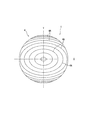
まず、本実施形態にかかる眼鏡レンズ1の構造を図1から図4に基づいて説明する。本実施形態は乱視補正用であって、図1及び図2は眼鏡レンズ1を凹レンズとした例であり、図3及び図4は眼鏡レンズ1を凸レンズとした例である。
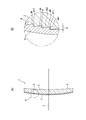
図1と図3は、それぞれ眼鏡レンズ1を正面から見た模式図である。図2と図4は、眼鏡レンズ1の断面図であって、(A)は全体を示す断面図であり、(B)は(A)の矢視Bで示される部分の拡大断面図である。
Hereinafter, an embodiment of the present invention will be described with reference to the drawings.
First, the structure of the
1 and 3 are schematic views of the
これらの図において、眼鏡レンズ1は、プラスチックレンズ基材2と、このプラスチックレンズ基材2の物体側面に設けられたコーティング層3とを備えて構成されている。
プラスチックレンズ基材2は、そのコーティング層3と面する面、つまり、物体側面に回折構造4が形成され、眼球側面にトーリック面5が形成されている。なお、図2及び図4において、左側が物体側であり、右側が眼球側である。図2は凹レンズを示すものであるため、プラスチックレンズ基材2の眼球側面のカーブが物体側面のカーブに比べて深く形成されている。図4は凸レンズを示すものであるため、プラスチックレンズ基材2の眼球側面のカーブが物体側面のカーブに比べ浅く形成されている。
In these drawings, the
The plastic lens substrate 2 has a
プラスチックレンズ基材2は熱硬化性樹脂で成形されるものである。この熱硬化性樹脂は、例えば、屈折率の高いテトラキス(2,3−エピチオプロピルチオ)スズ、テトラキス(2,3−エピチオプロピルチオ)ケイ素、テトラキス(2,3−エピチオプロピルチオ)ジルコニウム、テトラキス(2,3−エピチオプロピルチオ)ゲルマニウム、テトラキス(2,3−エピチオプロピルチオ)チタン等の化合物を重合して得られる熱硬化性樹脂を例示できる。
コーティング層3はアリルジグリコールカーボネート、その他の合成樹脂材料であって屈折率がn1であり、この屈折率n1はプラスチックレンズ基材2の屈折率n2とは同一ではない。
このコーティング層3の表面には必要に応じて図示しないプライマー層、ハードコート層、並びに反射防止層が形成されている。これらの層は、公知の素材を使用することができる。
The plastic lens substrate 2 is formed of a thermosetting resin. This thermosetting resin is, for example, tetrakis (2,3-epithiopropylthio) tin, tetrakis (2,3-epithiopropylthio) silicon, tetrakis (2,3-epithiopropylthio) having a high refractive index. Examples thereof include thermosetting resins obtained by polymerizing compounds such as zirconium, tetrakis (2,3-epithiopropylthio) germanium, tetrakis (2,3-epithiopropylthio) titanium.
The coating layer 3 is allyl diglycol carbonate or other synthetic resin material and has a refractive index of n1, and this refractive index n1 is not the same as the refractive index n2 of the plastic lens substrate 2.
A primer layer, a hard coat layer, and an antireflection layer (not shown) are formed on the surface of the coating layer 3 as necessary. A known material can be used for these layers.
回折構造4は、断面の山形形状部4Aが光軸Zから周縁部にかけて連続して形成された形状である。
隣り合う山形形状部4Aのピッチは乱視軸Xに沿ったピッチPsとこの乱視軸Xと直交する交差軸Yに沿ったピッチPs+cとでは異なるものであり、これらのピッチPs,Ps+cは光軸Zに近い部位より光軸Zから離れてレンズ周縁部に向かうに従って小さくなる。そのため、回折構造4の平面視は光軸Zを同心とする複数の楕円形の輪帯格子である。
回折構造4を構成する山形形状部4Aは、それぞれ光軸Zと略平行な立上面4A1と、この立上面4A1と連続して形成される傾斜面4A2とから構成されている。
回折構造4が光軸Zと平行に入射した光束が光軸Zから離隔するような凹レンズ効果を生じるようにするために、傾斜面4A2は、その垂直線分と光軸Zとの交点が眼鏡レンズ1より物体側(図2及び図4中左側)になるように形成されている。
The
The pitch of the adjacent mountain-
The chevron
In order to produce a concave lens effect in which the light beam incident on the
ここで、山形形状部4Aの立上面4A1の高さは格子厚dであり、この格子厚dは次の式1から求められる。
Here, the height of the rising surface 4A1 of the chevron

例えば、基準波長として水銀灯e線λ0=546.07nm(JIS T7330)を用いる。
そして、コーティング層3の材料をアリルジグリコールカーボネート(n1=1.50)とし、プラスチックレンズ基材2をチオウレタン系樹脂(三井化学株式会社MR-8、n2=1.60)とする。回折構造4で与える光路長差mを1波長(m=1)とする。
以上の条件での具体的な格子厚dは、d≒5.46μmである。
また、コーティング層3の材料をアリルジグリコールカーボネート(n1=1.50)とし、プラスチックレンズ基材2をエビスルフィド系樹脂(三井化学株式会社MR-174、n2=1.74)とする。回折構造4で与える光路長差を1波長(m=1)とする。
以上の条件での具体的な格子厚dは、d≒2.28μmである。
For example, mercury lamp e-line λ 0 = 546.07 nm (JIS T7330) is used as the reference wavelength.
The material of the coating layer 3 is allyl diglycol carbonate (n 1 = 1.50), and the plastic lens substrate 2 is a thiourethane resin (Mitsui Chemicals, Inc. MR-8, n 2 = 1.60). The optical path length difference m given by the
The specific lattice thickness d under the above conditions is d≈5.46 μm.
The material of the coating layer 3 is allyl diglycol carbonate (n 1 = 1.50), and the plastic lens base 2 is a disulfide resin (Mitsui Chemicals, Inc. MR-174, n 2 = 1.74). The optical path length difference given by the
The specific lattice thickness d under the above conditions is d≈2.28 μm.
光軸Zから数えてm番目の回折構造4の輪帯の半径(回折構造4のピッチ)は次の式2から求められる。なお、式中、fは焦点距離である。
The radius of the annular zone of the m-th
ここで、回折構造4を構成するプラスチックレンズ基材2の屈折率n2を考慮すると、m番目の回折構造輪帯の半径rmは式3の通りとなる。
Here, in consideration of the refractive index n2 of the plastic lens substrate 2 constituting the
従って、各回折構造の輪帯のピッチは式4の通りとなる。
Accordingly, the pitch of the ring zones of each diffractive structure is as shown in
![]()
![]()
例えば、回折構造4による効果として、乱視軸X方向にマイナス0.50ディオプター、乱視軸と直交する交差軸Y方向(乱視軸+90°)にマイナス1.00ディオプターを得る場合のピッチは表1に示す通りである。
Ps:乱視軸方向のピッチ
Ps+c:乱視軸と直交する方向のピッチ
λ0=546.07nm(基準波長として水銀灯e線)
Ax:乱視軸方向
Φs:乱視軸方向の回折構造による度数
Φs+c:乱視軸と直交する方向の回折構造による度数
Φs=−0.50ディオプター、Φs+c=−1.00ディオプター
For example, as an effect of the
P s : Astigmatic axis direction pitch
P s + c : Pitch in the direction perpendicular to the astigmatic axis λ 0 = 546.07 nm (mercury lamp e-line as the reference wavelength)
Ax: Astigmatic axis direction Φs: Frequency due to diffractive structure in astigmatic axis direction Φs + c: Frequency due to diffractive structure in direction perpendicular to astigmatic axis Φs = −0.50 diopter, Φs + c = −1.00 diopter
表1から乱視軸Xの方向のピッチPsと、乱視軸Xと直交する方向YのピッチPs+cとが異なることがわかる。しかも、これらのピッチPs, Ps+cは光軸Zから周縁部に向かうに従って小さくなる。そのため、格子厚dを一定とすると、傾斜面4A2が光軸Zと成す角度は周縁部に向かうに従って大きくなる。
なお、「レンズの光軸からの距離」と「その位置におけるピッチの逆数」とをグラフ表示すると図5及び図6のようになる。図5は乱視軸方向における「レンズの光軸からの距離」と「その位置におけるピッチの逆数」との関係を示すグラフであり、図6は乱視軸と直交する方向における「レンズの光軸からの距離」と「その位置におけるピッチの逆数」との関係を示すグラフである。
ここで、乱視軸方向のピッチと乱視軸と直行する方向のピッチは各輪帯において式5の関係にある。
The pitch P s of the direction of the astigmatic axis X from Table 1, the pitch P s + c in the direction Y orthogonal to the astigmatic axis X is found to differ. Moreover, these pitches P s and P s + c become smaller from the optical axis Z toward the periphery. Therefore, when the grating thickness d is constant, the angle formed by the inclined surface 4A2 with the optical axis Z increases as it goes toward the peripheral edge.
The “distance from the optical axis of the lens” and the “reciprocal of the pitch at that position” are graphically displayed as shown in FIGS. FIG. 5 is a graph showing the relationship between “the distance from the optical axis of the lens” and “the reciprocal of the pitch at that position” in the astigmatic axis direction, and FIG. 6 shows the “from the optical axis of the lens” in the direction orthogonal to the astigmatic axis. It is a graph which shows the relationship between "distance" and "the reciprocal of the pitch in the position."
Here, the pitch in the direction of the astigmatism axis and the pitch in the direction orthogonal to the astigmatism axis are in the relationship of
乱視軸方向の回折要素と乱視軸と直交する方向の回折要素を楕円で接続する場合は、 楕円(輪帯)の番号をm(m=0,1,2,・・・)とすると、式6で示される楕円の方程式で回折構造4が表せる。
When connecting the diffraction element in the direction of the astigmatism axis and the diffraction element in the direction orthogonal to the astigmatism axis by an ellipse, the number of the ellipse (ring zone) is m (m = 0, 1, 2,...) The
次に、前述の構成の眼鏡レンズ1を製造する方法について図7及び図8に基づいて説明する。
[レンズ型への回折構造形成工程]
後述するように、一対のレンズ型10を備えたモールド15に熱硬化性樹脂を注入してプラスチックレンズ基材2が重合されるが、一対のレンズ型10のうち一方のレンズ型10に、回折構造4と反転する転写形状40を形成しておく。そのため、レンズ型10の内面に感光材を薄く均一に塗付し、パターンを光で焼き付けて転写する。
Next, a method for manufacturing the
[Diffraction structure forming process to lens mold]
As will be described later, a thermosetting resin is injected into a
[モールド成形工程]
レンズ型10を用いて組み立てられるモールド成形工程について、図7に基づき説明する。
図7において、チャック12,13で保持された一対のレンズ型10を回転させながらテープ14を一対のレンズ型10の周縁部に巻き付け、このテープ14が一対のレンズ型10の全周面に巻き付けられたら図示しないカッタで所定位置を切断する。これにより、モールド15が成形される。
なお、図7中、符号16はレンズ型10の周面にテープ14を押さえつけるロールである。
[Molding process]
The molding process assembled using the
In FIG. 7, while rotating the pair of
In FIG. 7,
[プラスチック重合工程]
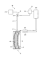
プラスチック重合工程を図8に基づいて説明する。図8にはプラスチックレンズ製造装置が示されている。
図8において、プラスチックレンズ製造装置は、モールド15の内部に熱硬化性樹脂を注入する樹脂注入機構20を備えており、この樹脂注入機構20は、モールド15の内部に樹脂原料を供給する供給部21と、供給される樹脂原料の量を制御する制御部22とを有する。
供給部21は、モールド15の内部に樹脂原料を注入するノズル211と、このノズル211の基端部に下端部が接続される樹脂原料流通管212と、この樹脂原料流通管212の上端に接続される原料貯蔵部213とを備えており、樹脂原料流通管212に設けられた注入制御バルブ214で開口量を制御することでノズル211から供給される樹脂原料の量が制御される。
制御部22は、注入制御バルブ214を制御する流量調節部221と、モールド15の内部に樹脂原料が所定位置まで注入されたことを検知するセンサ222及び樹脂原料の流量を切り換えるセンサ224と、これらのセンサ222,224からの信号を受けて流量調節部221を制御する制御部本体223とを備えている。
[Plastic polymerization process]
The plastic polymerization process will be described with reference to FIG. FIG. 8 shows a plastic lens manufacturing apparatus.
In FIG. 8, the plastic lens manufacturing apparatus includes a
The
The
プラスチックレンズ製造装置では、樹脂注入機構20によってモールド15の内部に熱硬化性樹脂を注入する。この際、樹脂原料の注入に伴って熱硬化性樹脂の液面が上昇するが、この液面が注入口14Aの付近に達してきたことをセンサ224で検出し、注入流量が徐々に下げられる。モールド15の内部に樹脂原料が満たされたことをセンサ222で検出したら、センサ222の信号が制御部22に送られ、樹脂原料の注入がストップされる。樹脂注入の後に注入口14Aを適宜な手段で封止する。注入口14Aが封止されたら、モールド15を炉に入れ、加熱硬化する。
これにより、プラスチックが重合されるとともにレンズ型10に形成された転写形状40がプラスチックレンズ基材2に転写される。
In the plastic lens manufacturing apparatus, a thermosetting resin is injected into the
As a result, the plastic is polymerized and the
[離型工程]
炉から取り出されたモールド15は、一対のレンズ型10の周面からテープ14が剥がされ、一対のレンズ型10が剥離されてプラスチックレンズ基材2が形成される。このプラスチックレンズ基材2の表面には回折構造4が形成されることになる。
[コーティング層形成工程]
プラスチックレンズ基材2の回折構造4が形成された面にコーティング層3を形成する。そのため、プラスチックレンズ基材2の回折構造4が形成された面に対向して図示しないレンズ型を配置し、このレンズ型とプラスチックレンズ基材2との間にコーティング層3を形成する合成樹脂を流入する。この合成樹脂が硬化した後、レンズ型を外す。
[眼球側面形成工程]
回折構造4とコーティング層3が予め設けられた眼鏡レンズブランクを用意しておき、プラスチックレンズ基材2の回折構造4が設けられた面の反対側、つまり、眼球側面に処方に応じて球面、非球面、トーリック面、累進面を加工する。この加工工程は従来と同様であり、例えば、研削等によって行われる。
その後、眼鏡レンズ1の表面にプライマー層、ハードコート層及び反射防止層を従来と同様の方法で形成する。
[Release process]
In the
[Coating layer forming process]
A coating layer 3 is formed on the surface of the plastic lens substrate 2 on which the
[Eyeball side surface formation process]
A spectacle lens blank in which the
Thereafter, a primer layer, a hard coat layer and an antireflection layer are formed on the surface of the
従って、本実施形態では次の作用効果を奏することができる。
(1)乱視軸Xと交差軸Yとでピッチが異なる回折構造4を眼鏡レンズ1に設けたから、大きな非点収差を付与するために乱視軸と交差軸とで曲率の差を大きくする必要がないので、レンズ周縁部の厚さの相違を小さくすることができる。そのため、眼鏡レンズ1にフレームを取り付けたとしても、フレームから眼鏡レンズ1の周縁部の一部がはみ出すことが少なくなり、眼鏡レンズ1の外観が改善される。しかも、眼鏡レンズ1自体の薄型化や軽量化も達成することができる。
Therefore, in the present embodiment, the following operational effects can be achieved.
(1) Since the
(2)回折構造4は同心上に形成された複数の楕円形から構成されているので、乱視軸Xと交差軸Yとの間での度数変化が滑らかになる。そのため、眼鏡をかけた使用者が目線を変更しても目が疲れることがない。
(3)回折構造4が物体側面に設けられるから、眼球側面の加工の有無にかかわらず非点収差を付与することができる。
(2) Since the
(3) Since the
(4)眼球側面に累進面の加工がされる場合、累進多焦点レンズによる調節力補正を併せて行うことができる。
(5)回折構造4は、光軸Zと平行に入射した光束が光軸から離隔するような凹レンズ効果を生じる構成としたので、大きな非点収差を効率的に付与することができる。そのため、乱視軸Xと交差軸Yとのレンズ周縁部の厚みの差をより小さくすることができる。
(4) When a progressive surface is processed on the side of the eyeball, adjustment force correction by a progressive multifocal lens can be performed together.
(5) Since the
(6)回折構造4は断面が連続した複数の山形形状部4Aとされ、光軸Zから周縁部に向かうに従って山形形状部4A間のピッチが小さくなるようにしたので、所定形状の山形形状を眼鏡レンズに形成するだけで非点収差を補正できる眼鏡レンズ1を容易に製造することができる。
(6) The
(7)回折構造4はプラスチックレンズ基材2に形成され、このプラスチックレンズ基材2の回折構造4の上にプラスチックレンズ基材2とは屈折率の異なるコーティング層3を形成したので、プラスチックレンズ基材2の上に形成された回折構造4がコーティング層3により保護されることになり、眼鏡レンズ1の耐久性を確保することができる。
(7) Since the
(8)レンズ型10に転写形状40をリソグラフィという簡易な手法で形成し、この転写形状40を、レンズ型10を用いてプラスチックレンズ基材2を重合する際に転写させて回折構造4を形成した。そのため、回折構造4をプラスチックレンズ基材2に容易に成形することができる。
(8) The
(9)回折構造4が予め物体側面に設けられた眼鏡レンズブランクを用意しておき、処方に応じて眼球側面に球面、非球面、トーリック面、累進面を加工する構成としたので、眼鏡レンズ1の部品の共通化を図ることができる。
(9) A spectacle lens blank in which the
次に、本実施形態の効果を確認するために実験例について説明する。
眼鏡レンズ1の最小厚み条件を表2に示す。ここで、CTは中心厚さであり、単位をmmで示す。minEdgeは最小レンズ縁厚であり、単位をmmで示す。
Next, experimental examples will be described in order to confirm the effects of the present embodiment.
Table 2 shows the minimum thickness condition of the
[実施例1]
実施例1は、レンズ全体として負の度数を持つマイナスレンズの場合であり、図1及び図2の眼鏡レンズ1に相当する。
まず、従来と同様に設計した球面設計乱視レンズについて説明する。この球面設計乱視レンズでは、処方度数(S−3.00、C−2.00、Ax180°)を、レンズ外径50mm、ベースカーブ2.00、屈折率1.60(MR-8)のプラスチックレンズ基材を用いて作製する。この際、プラスチックレンズ基材は、その中心厚1.300mm、最小レンズ縁厚2.891mm、最大レンズ縁厚3.985mmとなりレンズ縁厚差が1.094mmとなる。
[Example 1]
Example 1 is a case of a negative lens having a negative power as a whole, and corresponds to the
First, a spherically designed astigmatic lens designed in the same manner as in the prior art will be described. In this spherical design astigmatic lens, a prescription power (S-3.00, C-2.00, Ax180 °) is produced using a plastic lens base material having a lens outer diameter of 50 mm, a base curve of 2.00, and a refractive index of 1.60 (MR-8). . At this time, the plastic lens substrate has a center thickness of 1.300 mm, a minimum lens edge thickness of 2.891 mm, a maximum lens edge thickness of 3.985 mm, and a lens edge thickness difference of 1.094 mm.
これに対して、実施例1では、回折構造によるレンズ効果として、S−0.50、C−0.50、Ax180°を得てレンズ形状、特にレンズ縁厚の差を減少させた。
回折構造4よる凹レンズ効果としてS−0.50、C−0.50、Ax180°を得るため、レンズの度数はS−2.50、C−1.50、Ax180°とした。その時の各部の厚さは、レンズ中心厚が1.400mm、最小レンズ縁厚が2.723mm、最大レンズ縁厚が3.534mmとなり、レンズ縁厚差が0.811mmとなった。つまり、レンズ縁厚差は1.094mmから0.811mmとなり、0.283mmだけ減少する。この結果を表3に示す。
On the other hand, in Example 1, S-0.50, C-0.50, and Ax180 ° were obtained as the lens effect by the diffractive structure to reduce the difference in lens shape, particularly the lens edge thickness.
In order to obtain S-0.50, C-0.50, and Ax180 ° as the concave lens effect by the
また、回折構造4による凹レンズ効果としてS−0.50、C−0.50、Ax180°を得るための具体的な形状は次のように近似計算できる。なお、光線追跡法などの緻密な計算を行い、回折構造の最適化を行うことが望ましい。
回折構造4の上に形成されるコーティング層3を構成する材料としてアリルジグリコールカーボネート(n1=1.50)を用い、プラスチックレンズ基材2を三井化学株式会社MR-8(チオウレタン系樹脂、n2=1.60)とする。また、回折構造で与える光路長差を一波長とし、基準波長として水銀灯e線 λ0=546.07nm(JIS T7330)を用いる。
この場合、格子厚dは式1から導き出せる。その数値を式7に示す。
Further, the specific shape for obtaining S-0.50, C-0.50, and Ax180 ° as the concave lens effect by the
Allyl diglycol carbonate (n 1 = 1.50) is used as a material constituting the coating layer 3 formed on the
In this case, the grating thickness d can be derived from
[実施例2]
実施例2は、レンズ全体として正の度数を持つプラスレンズの場合であり、図3及び図4の眼鏡レンズ1に相当する。
まず、従来と同様に設計した球面設計乱視レンズについて説明する。この球面設計乱視レンズの場合、処方度数(S+3.00、C−2.00、Ax180°)を、レンズ外径50mm、ベースカーブ5.00、屈折率1.60(MR-8)のレンズ基材を用いて作製する。この際、プラスチックレンズ基材は、その中心厚が2.800mm、最小レンズ縁厚が1.234mm、最大レンズ縁厚が2.288mmとなり、レンズ縁厚差が1.054mmとなる。
[Example 2]
Example 2 is a case of a plus lens having a positive power as a whole, and corresponds to the
First, a spherically designed astigmatic lens designed in the same manner as in the prior art will be described. In the case of this spherical design astigmatic lens, a prescription power (S + 3.00, C−2.00, Ax180 °) is produced using a lens base material having a lens outer diameter of 50 mm, a base curve of 5.00, and a refractive index of 1.60 (MR-8). . At this time, the plastic lens substrate has a center thickness of 2.800 mm, a minimum lens edge thickness of 1.234 mm, a maximum lens edge thickness of 2.288 mm, and a lens edge thickness difference of 1.054 mm.
これに対して、実施例2では、回折構造によるレンズ効果として、S−0.50、C−0.50、Ax180°を得てレンズ形状、特にレンズ縁厚の差を減少させた。
回折構造4よる凹レンズ効果としてS−0.50、C−0.50、Ax180°を得るため、レンズの度数はS+3.50、C−1.50、Ax180°とした。その時、各部の厚さはレンズ中心厚が3.000mm、最小レンズ縁厚が1.174mm、最大レンズ縁厚が1.961mm、レンズ縁厚差が0.787mmとなった。つまり、レンズ縁厚の差は1.054mmから0.787mmとなって0.267mmだけ減少した。その結果を表4に示す。
On the other hand, in Example 2, S-0.50, C-0.50, and Ax180 ° were obtained as the lens effect by the diffractive structure to reduce the difference in lens shape, particularly the lens edge thickness.
In order to obtain S-0.50, C-0.50, and Ax180 ° as the concave lens effect by the
また、回折構造4による凹レンズ効果としてS−0.50、C−0.50、Ax180°を得るための具体的な形状は次のように近似計算できる。
回折構造4の上に形成されるコーティング層3を構成する材料としてアリルジグリコールカーボネート(n1=1.50)を用い、プラスチックレンズ基材2を三井化学株式会社MR-8(チオウレタン系樹脂、n2=1.60)とする。また、回折構造で与える光路長差を一波長とし、基準波長として水銀灯e線 λ0=546.07nm(JIS T7330)を用いる。
この場合、格子厚dは式7に示されるものである。
Further, the specific shape for obtaining S-0.50, C-0.50, and Ax180 ° as the concave lens effect by the
Allyl diglycol carbonate (n 1 = 1.50) is used as a material constituting the coating layer 3 formed on the
In this case, the lattice thickness d is expressed by Equation 7.
[実施例3]
実施例3は、レンズの一方の軸上で正の度数を持ち、直交する他方の軸上では負の度数を持つミックスレンズの場合である。
まず、従来と同様に設計した球面設計乱視レンズについて説明する。この球面設計乱視レンズの場合、処方度数(S+3.00、C−4.00、Ax180°)を、レンズ外径50mm、ベースカーブ5.00、屈折率1.60(MR-8)のレンズ基材を用いて作製する。この際、プラスチックレンズ基材は、その中心厚が2.800mm、最小レンズ縁厚が1.234mm、最大レンズ縁厚が3.366mm、レンズ縁厚差が2.132mmとなる、
[Example 3]
Example 3 is a case of a mixed lens having a positive power on one axis of the lens and a negative power on the other orthogonal axis.
First, a spherically designed astigmatic lens designed in the same manner as in the prior art will be described. In the case of this spherical design astigmatic lens, a prescription power (S + 3.00, C−4.00, Ax180 °) is produced using a lens base material having a lens outer diameter of 50 mm, a base curve of 5.00, and a refractive index of 1.60 (MR-8). . At this time, the plastic lens base material has a center thickness of 2.800 mm, a minimum lens edge thickness of 1.234 mm, a maximum lens edge thickness of 3.366 mm, and a lens edge thickness difference of 2.132 mm.
これに対して、実施例3では、回折構造によるレンズ効果として、S−0.50、C−0.50、Ax180°を得てレンズ形状、特にレンズ縁厚の差を減少させた。
回折構造4による凹レンズ効果としてS−0.50、C−0.50、Ax180°を得るため、レンズの度数はS+3.50、C−3.50、Ax180°とした。その時、各部の厚さはレンズ中心厚が3.000mm、最小レンズ縁厚が1.174mm、最大レンズ縁厚が3.025mm、レンズ縁厚差が1.851mmとなった。つまり、レンズ縁厚の差は2.132mmから1.851mmとなって、0.281mmだけ減少した。その結果を表5に示す。
On the other hand, in Example 3, S-0.50, C-0.50, and Ax180 ° were obtained as the lens effect by the diffractive structure to reduce the difference in lens shape, particularly the lens edge thickness.
In order to obtain S-0.50, C-0.50, and Ax180 ° as the concave lens effect by the
また、回折構造よるレンズ効果としてS−0.50、C−0.50、Ax180°を得るための具体的な形状は次のように近似計算できる。回折構造をコーティングする材料としてアリルジグリコールカーボネート(n1=1.50)を用い、プラスチックレンズ基材2を三井化学株式会社MR-8(チオウレタン系樹脂、n2=1.60)とする。また、回折構造4で与える光路長差を一波長とし、基準波長として水銀灯e線 λ0=546.07nm(JIS T7330)を用いる。
この場合、格子厚dは式7に示されるものである。
Further, the specific shape for obtaining S−0.50, C−0.50, and Ax180 ° as the lens effect by the diffractive structure can be approximated as follows. Allyl diglycol carbonate (n 1 = 1.50) is used as a material for coating the diffractive structure, and the plastic lens substrate 2 is MR-8 (thiourethane resin, n 2 = 1.60). The optical path length difference given by the
In this case, the lattice thickness d is expressed by Equation 7.
なお、本発明は前述の実施形態に限定されるものではなく、本発明の目的を達成できる範囲での変形、改良等は本発明に含まれるものである。
例えば、前記実施形態では、回折構造4を同心上に形成された複数の楕円形から構成したが、本発明では、同心上に形成された複数の三角形や同心上に形成された複数の矩形を回折構造としてもよい。
また、必ずしもコーティング層3を設けることを要しない。
さらに、基材はプラスチック以外、例えば、ガラスから成形するものでもよい。
そして、回折構造4をプラスチックレンズ基材2に形成する方法としてはリソグラフィによりレンズ型10に転写形状40を形成するものに限定されるものではなく、例えば、レーザを用いてレンズ基材に回折構造4を直接形成するものでもよい。
It should be noted that the present invention is not limited to the above-described embodiment, and modifications, improvements, and the like within the scope that can achieve the object of the present invention are included in the present invention.
For example, in the above embodiment, the
Further, it is not always necessary to provide the coating layer 3.
Further, the substrate may be formed from glass other than plastic, for example.
The method of forming the
本発明は、プラスチック、その他の材料から形成される眼鏡レンズに利用することができる。 The present invention can be used for spectacle lenses formed of plastic or other materials.
1…眼鏡レンズ、2…プラスチックレンズ基材、3…コーティング層、4…回折構造、4A…山形形状部、40…転写形状、10…レンズ型
DESCRIPTION OF
Claims (10)
Priority Applications (1)
| Application Number | Priority Date | Filing Date | Title |
|---|---|---|---|
| JP2007159169A JP2008310160A (en) | 2007-06-15 | 2007-06-15 | Eyeglasses lens and method for manufacturing eyeglasses lens |
Applications Claiming Priority (1)
| Application Number | Priority Date | Filing Date | Title |
|---|---|---|---|
| JP2007159169A JP2008310160A (en) | 2007-06-15 | 2007-06-15 | Eyeglasses lens and method for manufacturing eyeglasses lens |
Publications (2)
| Publication Number | Publication Date |
|---|---|
| JP2008310160A true JP2008310160A (en) | 2008-12-25 |
| JP2008310160A5 JP2008310160A5 (en) | 2010-07-15 |
Family
ID=40237796
Family Applications (1)
| Application Number | Title | Priority Date | Filing Date |
|---|---|---|---|
| JP2007159169A Withdrawn JP2008310160A (en) | 2007-06-15 | 2007-06-15 | Eyeglasses lens and method for manufacturing eyeglasses lens |
Country Status (1)
| Country | Link |
|---|---|
| JP (1) | JP2008310160A (en) |
Cited By (4)
| Publication number | Priority date | Publication date | Assignee | Title |
|---|---|---|---|---|
| JP2016500842A (en) * | 2012-10-17 | 2016-01-14 | ローデンストック.ゲゼルシャフト.ミット.ベシュレンクテル.ハフツング | Fabrication of spectacle lenses with protected microstructure |
| JP2016136262A (en) * | 2009-01-30 | 2016-07-28 | ジョンソン・アンド・ジョンソン・ビジョン・ケア・イン | Ophthalmic lens forming method |
| US9857607B2 (en) | 2007-08-21 | 2018-01-02 | Johnson & Johnson Vision Care, Inc. | Apparatus for formation of an ophthalmic lens precursor and lens |
| US11364696B2 (en) | 2020-09-18 | 2022-06-21 | Johnson & Johnson Vision Care, Inc | Apparatus for forming an ophthalmic lens |
Citations (4)
| Publication number | Priority date | Publication date | Assignee | Title |
|---|---|---|---|---|
| JPH032718A (en) * | 1989-02-06 | 1991-01-09 | Essilor Internatl (Cie Gen Opt) | Lens for correcting astigmatism |
| JPH03107076A (en) * | 1989-09-19 | 1991-05-07 | Asahi Chem Ind Co Ltd | Vibration restraint for building |
| JP2000284238A (en) * | 1999-01-29 | 2000-10-13 | Seiko Epson Corp | Spectacle lens |
| JP2002107521A (en) * | 2000-09-28 | 2002-04-10 | Canon Inc | Die for diffractive optical element, diffractive optical element and its manufacturing method |
-
2007
- 2007-06-15 JP JP2007159169A patent/JP2008310160A/en not_active Withdrawn
Patent Citations (4)
| Publication number | Priority date | Publication date | Assignee | Title |
|---|---|---|---|---|
| JPH032718A (en) * | 1989-02-06 | 1991-01-09 | Essilor Internatl (Cie Gen Opt) | Lens for correcting astigmatism |
| JPH03107076A (en) * | 1989-09-19 | 1991-05-07 | Asahi Chem Ind Co Ltd | Vibration restraint for building |
| JP2000284238A (en) * | 1999-01-29 | 2000-10-13 | Seiko Epson Corp | Spectacle lens |
| JP2002107521A (en) * | 2000-09-28 | 2002-04-10 | Canon Inc | Die for diffractive optical element, diffractive optical element and its manufacturing method |
Cited By (8)
| Publication number | Priority date | Publication date | Assignee | Title |
|---|---|---|---|---|
| US9610742B2 (en) | 2007-08-21 | 2017-04-04 | Johnson & Johnson Vision Care, Inc. | Apparatus for formation of an ophthalmic lens precursor and lens |
| US9857607B2 (en) | 2007-08-21 | 2018-01-02 | Johnson & Johnson Vision Care, Inc. | Apparatus for formation of an ophthalmic lens precursor and lens |
| US10126567B2 (en) | 2007-08-21 | 2018-11-13 | Johnson & Johnson Vision Care, Inc. | Apparatus for formation of an ophthalmic lens precursor and lens |
| US10571718B2 (en) | 2007-08-21 | 2020-02-25 | Johnson & Johnson Vision Care, Inc | Apparatus for formation of an ophthalmic lens precursor and lens |
| US10901319B2 (en) | 2007-08-21 | 2021-01-26 | Johnson & Johnson Vision Care, Inc. | Apparatus for forming an ophthalmic lens |
| JP2016136262A (en) * | 2009-01-30 | 2016-07-28 | ジョンソン・アンド・ジョンソン・ビジョン・ケア・イン | Ophthalmic lens forming method |
| JP2016500842A (en) * | 2012-10-17 | 2016-01-14 | ローデンストック.ゲゼルシャフト.ミット.ベシュレンクテル.ハフツング | Fabrication of spectacle lenses with protected microstructure |
| US11364696B2 (en) | 2020-09-18 | 2022-06-21 | Johnson & Johnson Vision Care, Inc | Apparatus for forming an ophthalmic lens |
Similar Documents
| Publication | Publication Date | Title |
|---|---|---|
| EP3283008B1 (en) | Ophthalmic lens with graded microlenses | |
| EP3717964B1 (en) | Optical lens | |
| EP1982228B1 (en) | Toric contact lenses | |
| KR102553989B1 (en) | Contact lens and its manufacturing method | |
| WO2021059887A1 (en) | Spectacle lens and method for manufacturing same | |
| JP2008310160A (en) | Eyeglasses lens and method for manufacturing eyeglasses lens | |
| EP2042911A1 (en) | Method for designing spectacle lens, and spectacles | |
| JP2009098622A (en) | Method for designing spectacle lens, and spectacles | |
| WO2021181885A1 (en) | Spectacle lens | |
| JP7358619B2 (en) | eyeglass lenses | |
| JP2009069462A (en) | Eyeglass lens, and method of manufacturing eyeglass lens | |
| TW201809812A (en) | Ophthalmic lenses and methods of manufacturing the same | |
| CN113391464A (en) | Out-of-focus glasses lens | |
| WO2023042572A1 (en) | Spectacle lens | |
| JP2009139786A (en) | Spectacle lens and method for manufacturing the same | |
| EP4344863A1 (en) | Manufacturing method of an optical article incorporating optical elements by inkjet printing | |
| KR101556995B1 (en) | Manufacturing method of toric lens | |
| CN218938687U (en) | Embedded intangible annular microlens zoom lens | |
| JP7177959B1 (en) | spectacle lenses | |
| CN220752443U (en) | Spectacle lens and spectacles | |
| CN217718323U (en) | Spectacle lens and spectacles | |
| CN218068482U (en) | Astigmatic out-of-focus spectacle lens and spectacles | |
| JP7217676B2 (en) | Spectacle lens and its design method | |
| EP4091805A1 (en) | A method for improved coating of an optical article comprising optical elements | |
| WO2023171061A1 (en) | Eyeglass lens and design method for eyeglass lens |
Legal Events
| Date | Code | Title | Description |
|---|---|---|---|
| A521 | Written amendment |
Effective date: 20100601 Free format text: JAPANESE INTERMEDIATE CODE: A523 |
|
| A621 | Written request for application examination |
Free format text: JAPANESE INTERMEDIATE CODE: A621 Effective date: 20100601 |
|
| A977 | Report on retrieval |
Effective date: 20110803 Free format text: JAPANESE INTERMEDIATE CODE: A971007 |
|
| A131 | Notification of reasons for refusal |
Effective date: 20110809 Free format text: JAPANESE INTERMEDIATE CODE: A131 |
|
| A761 | Written withdrawal of application |
Free format text: JAPANESE INTERMEDIATE CODE: A761 Effective date: 20111007 |