EP2042911A1 - Method for designing spectacle lens, and spectacles - Google Patents
Method for designing spectacle lens, and spectacles Download PDFInfo
- Publication number
- EP2042911A1 EP2042911A1 EP08017058A EP08017058A EP2042911A1 EP 2042911 A1 EP2042911 A1 EP 2042911A1 EP 08017058 A EP08017058 A EP 08017058A EP 08017058 A EP08017058 A EP 08017058A EP 2042911 A1 EP2042911 A1 EP 2042911A1
- Authority
- EP
- European Patent Office
- Prior art keywords
- spectacle lens
- lens
- spectacle
- optical
- line
- Prior art date
- Legal status (The legal status is an assumption and is not a legal conclusion. Google has not performed a legal analysis and makes no representation as to the accuracy of the status listed.)
- Withdrawn
Links
Images


Classifications
-
- G—PHYSICS
- G02—OPTICS
- G02C—SPECTACLES; SUNGLASSES OR GOGGLES INSOFAR AS THEY HAVE THE SAME FEATURES AS SPECTACLES; CONTACT LENSES
- G02C13/00—Assembling; Repairing; Cleaning
- G02C13/003—Measuring during assembly or fitting of spectacles
- G02C13/005—Measuring geometric parameters required to locate ophtalmic lenses in spectacles frames
-
- G—PHYSICS
- G02—OPTICS
- G02C—SPECTACLES; SUNGLASSES OR GOGGLES INSOFAR AS THEY HAVE THE SAME FEATURES AS SPECTACLES; CONTACT LENSES
- G02C7/00—Optical parts
- G02C7/02—Lenses; Lens systems ; Methods of designing lenses
Definitions
- the present invention relates to a method for designing a spectacle lens to be mounted in a spectacle frame having a large bend angle such as a wraparound type spectacle frame.
- a spectacle frame of the wraparound type has become popular, especially as sports sunglasses.
- the spectacle frame of the wraparound type has a characteristic that, since the spectacle frame of the wraparound type has a large bend angle to bend around a face, even the sides of the face are covered by lenses and the field of view is wide. Therefore, a spectacle frame of the wraparound type is popular among athletes as a frame for safety spectacles used during sports and for general eye protection.
- the wraparound type spectacle lens is provided with an optical convex surface on an object side and an optical concave surface on an eye side and is mounted in the spectacle frame in a manner tilting with respect to a line of sight ( JP-A-2005-284059 ).
- the optical concave surface of the spectacle lens is prescribed for near-sightedness correction, far-sightedness correction or the like depending on eyesight of a user.
- spectacle lenses are typically designed in variation, but spectacle frames in which the spectacle lenses are mounted are often standardized.
- a spectacle lens is mounted in a spectacle frame using an outer shape of the spectacle frame as a reference.
- a spectacle lens is mounted in a spectacle frame so that an optical convex surface on an object side conforms to the outer shape of the spectacle frame.
- a spectacle lens In a spectacle lens, light that enters from the object side refracts at the optical convex surface and linearly travels in the lens, before the light refracts again at the optical concave surface and enters a pupil of a user.
- the optical concave surface on the eye side is prescribed in correspondence with eyesight or the like of a user, the surface differs from one lens to another.
- a typical spectacle lens is mounted in a spectacle frame using only the outer shape of the spectacle frame as a reference.
- a prescription made on the optical concave surface on an eye side may cause the optical concave surface to form an inappropriate angle with respect to the spectacle frame.
- An advantage of some aspects of the invention is to provide: a method for designing a spectacle lens that is less likely to cause an error irrespective of prescription made on an optical concave portion on an eye side; and spectacles.
- the invention is made to deal with errors such as a dioptric power error that occur when the spectacle lens is mounted in a spectacle frame with the optical surface tilting with respect to the appropriate angle.
- a method according to an aspect of the invention for designing a spectacle lens that includes an optical convex surface on an object side of the spectacle lens and an optical concave surface on an eye side of the spectacle lens and is mounted in a spectacle frame in a manner tilting with respect to a forward sight line, the optical convex surface being spherical, the optical concave surface being optically curved according to a prescription includes: defining a design reference point at an intersection of the optical concave surface and the forward sight line; and determining an angle formed by a tangent line at the design reference point and a perpendicular plane perpendicular to the forward sight line as a lens tilt angle ⁇ with which the spectacle lens is mounted in the spectacle frame.
- the lens tilt angle ⁇ is obtained for each spectacle lens, and the spectacle lens is mounted in the spectacle frame in correspondence with the lens tilt angle ⁇ .
- unfavorable tilt of the optical concave surface can be prevented by setting the lens tilt angle ⁇ , so that the spectacle lens can be mounted in the spectacle frame with the optical concave surface being in the appropriate angle irrespective of prescription for near-sightedness, far-sightedness or the like. Therefore, the average dioptric power error, the astigmatic aberration, and a prismatic error are reduced to prevent eyestrain or the like suffered by a spectacle user.
- the optical concave surface is aspherical.
- the average dioptric power error, the astigmatic aberration, and the prismatic error can be further reduced.
- the method for designing the spectacle lens further includes: obtaining the lens tilt angle ⁇ from: an inter-pupil distance; an edged lens width of the spectacle lens; a front bend angle formed by a line and the perpendicular plane perpendicular to the forward sight line; the line connecting peripheral edges that oppose to each other across the optical convex surface; a bridge length defined by a dimension between the spectacle lens and a neighboring spectacle lens used together with the spectacle lens; a front curvature indicated by a radius of curvature of the optical convex surface; and a center thickness of the spectacle lens.
- the method for designing the spectacle lens further includes: obtaining a formula of a sphere of the optical convex surface of the spectacle lens from the edged lens width of the spectacle lens, the front bend angle, the bridge length, and the front curvature; obtaining a formula of a tangent line of the sphere that passes through an intersection of the sphere and a parallel line parallel to the forward sight line; selecting an appropriate incident light ray by setting requirements of a plurality of light rays entering a pupil for the equation of the tangent line and calculating to obtain the appropriate incident light ray whose corresponding exiting light ray that exits from the spectacle lens passes through the pupil under the requirements, and determining an angle formed by an appropriate tangent line associated with the appropriate incident light ray and the perpendicular plane as the lens tilt angle ⁇ .
- the formula of the sphere of the optical convex surface on the object side is used with a parallel line parallel to the forward sight line to obtain a formula of the parallel line touching the sphere, that is, the tangent line on the sphere.
- the optical convex surface on the object side of the spectacle lens and the optical concave surface on the eye side of the spectacle lens are approximated to a plate-shaped prism having two parallel surfaces.
- a light ray entering the object-side surface of the plate prism is refracted once and travels linearly in the plate. Subsequently, the light ray is refracted again and exits to the eye side from the eye side surface.
- an exiting position is obtained by simulation for each of the light rays, and one of the incident light.rays exiting at a position that aligns with the forward sight line is obtained by, for example, the convergent calculating method.
- the angle formed by the incident surface of the incident light ray whose corresponding exiting light ray aligns with the forward sight line is determined as the lens tilt angle ⁇ .
- the tilt of the optical concave surface can be obtained by calculation using the aforementioned parameters irrespective of the prescription, so that more accurate lens tilt angle ⁇ can be determined.
- Spectacles according to another aspect of the invention includes: a spectacle lens designed by a method for designing a spectacle lens according to the above arrangement(s); and a spectacle frame in which the spectacle lens is mounted.
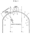
- Fig. 1 is a schematic horizontal cross section of spectacles according to an exemplary embodiment of the invention.
- Fig. 3 is a schematic view for describing a method for designing a spectacle lens.
- Fig. 1 is a schematic horizontal cross section of the spectacle according to the exemplary embodiment.
- Fig. 1 spectacles are provided with two spectacle lenses 1, each of which is mounted in the spectacle frame 2 in a manner tilting with respect to a forward sight line P.
- the spectacle lens 1 is a meniscus lens having an optical convex surface 11 on an object side and an optical concave surface 12 on an eye side.
- the spectacle lens 1 is shaped in a sphere, and a radius of curvature, that is, a front curvature r, of the optical convex surface 11 has a predetermined dimension.
- the spectacle frame 2 is a spectacle frame having a bend angle of 200° or larger such as a wraparound type spectacle frame or the like.
- a bridge 21 whose front side is substantially spherically curved and with which the spectacle is supported to a nose, a temple 22 with which the spectacle is supported to an ear, and a rim 23 in which the spectacle lens 1 is mounted are integrally formed in the spectacle frame 2.
- the optical convex surface 11 of the spectacle lens 1 is shaped in a sphere.
- the spectacle lens 1 is mounted in the spectacle frame 2 in a manner that the sphere of the spectacle lens 1 corresponds to the curved portion of the sphere on the front side of the spectacle frame 2.
- the optical concave surface 12 is prescribed for near-sightedness, far-sightedness or the like as necessary, the optical concave surface 12 is aspherical.
- Two forward sight lines P are defined in parallel to each other in the spectacles.
- a distance between the forward sight lines P will be referred to as an inter-pupil distance PD.
- the inter-pupil distance PD is modified for each user.
- a nose width dimension of the bridge 21 of the spectacle frame 2 is defined as a bridge length L.
- the bridge length L is a linear dimension on the front side of the bridge 21 in a plane including the forward sight line P.
- the bridge length L is also a dimension between edges of the optical convex surfaces 11 of the neighboring spectacle lenses 1.
- Fig. 2 is an enlarged schematic figure of the spectacle lens 1.
- the optical concave surface 12 meets the forward sight line P at a design reference point Pi.
- a tangent line C of the optical concave surface 12 is in a horizontal plane including the two forward sight lines P and passes through the design reference point Pi.
- the tangent line C and the plane Q perpendicular to the forward sight lines P form a lens tilt angle ⁇ .
- a thickness of the spectacle lens 1 at the design reference point Pi is referred to a center thickness t.
- Fig. 3 is a schematic view that helps describe a method for designing the spectacle lens 1.
- An equation of the sphere of the optical convex surface 11 of the spectacle lens is obtained from the edged lens width W, the front bend angle a, the bridge length L, and the front curvature r.
- Xo, Yo, and Zo which are coordinates of a center of the sphere, are obtained from the edged lens width W, the front bend angle a, and the bridge length L of the spectacle lens 1.
- the tangent line Cn of the sphere which passes through an intersection of the sphere and a light ray Pn parallel to the forward sight lines P, is also obtained.
- the optical convex surface 11 on the object side of the spectacle lens 1 and the optical concave surface 12 on the eye side of the spectacle lens 1 are approximated to two tangent lines Cn parallel to each other.
- a dimension of the spectacle lens 1 is determined so that the distance between the two tangent lines Cn is the same as the center thickness t of the spectacle lens 1.
- the spectacle lens 1 in which the optical concave surface 12 and the optical convex surface 11 have different tilt angles is assumed to be a plate-shaped prism which has an incident surface and an exit surface parallel to each other.
- the light ray Pn having entered the object-side surface refracts once and travels linearly in the inside. Subsequently, the light ray Pn refracts again at the eye side surface and exits to the eye side to become a light ray Pn'.
- An angle ⁇ n formed by the tangent line Cn (i.e., the incident surface) and the plane Qn perpendicular to the forward sight line P varies depending on a position of the incident light ray Pn in the horizontal plane.
- the incident light ray Pn is a light ray P 1 taking a rightmost position
- the light ray P 1 refracts at the tangent line C 1 on the incident side and refracts again at the tangent line C 1 on the exit side to become an exiting light ray P 1 '.
- the plane Q 1 and the tangent line C 1 form an angle ⁇ 1 .
- the incident light ray Pn is a light ray P 2 taking a leftmost position
- the light ray P 2 refracts at the tangent line C 2 on the incident side and refracts again at the tangent line C 2 on the exit side to become an exiting light ray P 2 '.
- the plane Q 2 and the tangent line C 2 form an angle ⁇ 2 .
- the angle ⁇ 2 is larger than the angle ⁇ 1 .
- the exiting light ray Pn' is simulated for each of the incident light rays Pn.
- a first light ray P 1 is radiated, and a distance (a dimension in the Y-axis direction of Fig. 3 ) between an exiting light ray P 1 ' of this light ray P 1 and the forward sight line P is obtained. If the distance takes a plus value, a second light ray P 2 is radiated from a minus direction, a distance between the exiting light ray P 2 ' of the light ray P 2 and the forward sight line P is obtained. If the distance takes a minus value, a third light ray P 3 is radiated at a position between the light rays P 1 and P 2 . This simulation is repeated until the exiting light ray Pn' aligns with the forward sight line P.
- the incident surface (e.g., the tangent line C 3 ) of such an aligning incident light ray Pn (e.g., the incident light ray P 3 ) and the perpendicular plane Q 3 form an angle ⁇ 3 , which is determined as the lens tilt angle ⁇ .
- a prism adjustment is conducted as necessary.
- a method for manufacturing the spectacle lens 1 designed according to the designing method for the exemplary embodiment will be described with reference to Fig. 4 .
- a semifinished lens blank is molded by cast molding to obtain the spectacle lens 1.
- Figs. 4(a) to (d) are schematic cross sections showing a manufacturing process of the spectacle lens 1.
- the first casting mold 110 has a convex surface 111 for molding the concave surface side of the semifinished lens blank and a lower surface 112 not for molding.
- the second casting mold 120 has a concave surface 121 for molding the convex surface of the semifinished lens blank and an upper surface 122 not for molding.
- the first casting mold 110 is a glass mold. Both the convex surface 111 for molding and the lower surface 112 are spherically formed. The first casting mold 110 has a substantially uniform thickness. Not only the convex surface 111 but also the lower surface 112 are optically formed. A spherical center of the convex surface 111 and a spherical center of the lower surface 112 both reside on a geometric center line, and the convex surface 111 for molding and the lower surface 112 are rotationally symmetrical surfaces whose symmetrical axis is formed by the geometric center line.
- the second casting mold 120 is a glass mold. Both the molding surface of the concave surface 121 and the upper surface 122 are spherical. The upper surface 122 a well as the concave surface 121 are optically formed. A spherical center of the upper surface 122 resides on a geometric center line, so that the upper surface 122 is a rotationally symmetric surface whose symmetric axis is formed by the geometric center line. The concave surface 121 is a tilted sphere whose center is apart from the geometric center line toward the ear. Accordingly, the second casting mold 120 does not have a uniform thickness. A prismatic refractive effect is generated on a geometric center line of a lens whose both surfaces are spherical.and whose thickness is uneven.
- a fitting point is set as a reference point on a front surface of the lens. More specifically, the fitting point is set at a predetermined position apart from the geometric center of the concave surface 121 of the second casting mold 120 where the thickness of the second casting mold 120 is increased.
- a hidden mark (not shown) for notifying a position of the referential fitting point is marked. For example, the hidden mark is marked at positions opposite across and equally distant from the fitting point. The hidden mark is transcribed on the convex surface 31 of the semifinished lens blank 3 (see, Fig. 4(c) ).
- the first casting mold 110 and the second casting mold 120 are disposed so that, when externally observed, lateral sides of the first casting mold 110 and the second casting mold 120 align in a manner that the convex surface 111 of the first casting mold 110 and the concave surface 121 of the second casting mold 120 face each other and are apart from each other by a predetermined distance. While positions of the first casting mold 110 and the second casting mold 120 are maintained, an adhesive tape 130 is wound around the lateral side of the first casting mold 110 and the lateral side of the second casting mold 120 in a manner striding over a boundary between the lateral side of the first casting mold 110 and the lateral side of the second casting mold 120. Then, a gap between the first casting mold 110 and the second casting mold 120 is sealed by the adhesive tape 130 to form a cavity 140 to provide a casting mold 150 for lens cast molding.
- a lens material is filled in the cavity 140, which is a sealed space surrounded by the first casting mold 110 and the second casting mold 120 of the casting mold 150 and the adhesive tape 130. Subsequently, light energy or heat energy is applied to the lens material for polymerization curing.
- the adhesive tape 130 is peeled away and the first casting mold 110 and the second casting mold 120 are separated to obtain the semifinished lens blank 3 as shown in Fig. 4(c) .
- the convex surface 31 and the concave surface 32 of the semifinished lens blank 3 each includes a sphere and has a prismatic refractive effect on the geometric center line.
- the semifinished lens blank 3 is an eccentric lens whose fitting point is deviated from the geometric center toward the nose.
- the concave surface 32 on the eye side of the obtained semifinished lens blank 3 is cut and grinded before being mirror-finished to yield the optical concave surface 12.
- the intersection of the optical concave surface 12 and the forward sight lines P is set as the design reference point Pi.
- a lens tilt angle ⁇ formed by the tangent line C at the design reference point Pi and the plane Q perpendicular to the forward sight lines P is used to design the spectacle lens 1. Therefore, even if the optical concave surface 12 has a complicated aspherical shape as a result of a prescription, occurrence of an average dioptric power error, an astigmatic aberration, or a prismatic error is prevented.
- the lens tilt angle ⁇ can be obtained from the inter-pupil distance PD, the edged lens width W, the front bend angle a, the bridge length L, the front curvature r, and the center thickness t of the spectacle lens 1.
- the lens tilt angle ⁇ can be easily obtained by simulation with a computer or the like.
- the lens tilt angle ⁇ is determined as follows.
- the equation of the sphere of the optical convex surface of the spectacle lens is obtained from the edged lens width W, the front bend angle a, the bridge length L, and the front curvature r of the spectacle lens 1.
- the equation of the tangent line Cn of the sphere that passes through the intersection of the sphere and the light ray Pn parallel to the forward sight lines P is obtained.
- the requirements of the light rays Pn that enter the pupil I are set for the formula of the tangent line C.
- the appropriate incident light ray is selected by calculating the light ray Pn whose counterpart exiting light ray Pn' passes through the pupil I under the aforementioned requirements.
- lens tilt angle ⁇ An angle formed by the tangent line and the perpendicular plane in the case of the selected light ray is determined as the lens tilt angle ⁇ . Because the optical convex surface 11 on the object side and the optical concave surface 12 on the eye side of the spectacle lens 1 are approximated to be two parallel surfaces parallel to each other to facilitate calculation, the lens tilt angle ⁇ can be obtained by the convergent calculating method or the like irrespective of the prescription. Therefore, a more accurate lens tilt angle ⁇ can be set.
- the first casting mold 110 having the spherical optical convex surface 111 and the second casting mold 120 having the spherical optical concave surface 121 are opposed to each other in a manner that the geometric centers of the molds align with each other and that the semifinished lens blank 3 to be molded has a prismatic refractive effect on the geometric center line. Therefore, the lens shape of the spectacle lens suitable for the wraparound type spectacle frame can be obtained even using the semifinished lens blank having a diameter for a normal spectacle lens.
- the lens tilt angle ⁇ is obtained by the convergent calculating method or the like.
- a method for obtaining the lens tilt angle ⁇ is not limited to the convergent calculating method. For instance, other calculating methods commonly used in mathematics may be employed.
- the optical concave surface 12 may be spherical.
- the invention can be applied to a spectacle lens mounted in a wraparound type spectacle frame.
Abstract
Description
- The entire disclosure of Japanese Patent Application No.
2007-254293, filed September 28, 2007 No. 2008-173311, filed July 2, 2008 - The present invention relates to a method for designing a spectacle lens to be mounted in a spectacle frame having a large bend angle such as a wraparound type spectacle frame.
- In recent years, a spectacle frame of the wraparound type has become popular, especially as sports sunglasses. The spectacle frame of the wraparound type has a characteristic that, since the spectacle frame of the wraparound type has a large bend angle to bend around a face, even the sides of the face are covered by lenses and the field of view is wide. Therefore, a spectacle frame of the wraparound type is popular among athletes as a frame for safety spectacles used during sports and for general eye protection.
- The wraparound type spectacle lens is provided with an optical convex surface on an object side and an optical concave surface on an eye side and is mounted in the spectacle frame in a manner tilting with respect to a line of sight (
JP-A-2005-284059 - The optical concave surface of the spectacle lens is prescribed for near-sightedness correction, far-sightedness correction or the like depending on eyesight of a user. Thus, spectacle lenses are typically designed in variation, but spectacle frames in which the spectacle lenses are mounted are often standardized.
- Typically, a spectacle lens is mounted in a spectacle frame using an outer shape of the spectacle frame as a reference. Specifically, a spectacle lens is mounted in a spectacle frame so that an optical convex surface on an object side conforms to the outer shape of the spectacle frame.
- In a spectacle lens, light that enters from the object side refracts at the optical convex surface and linearly travels in the lens, before the light refracts again at the optical concave surface and enters a pupil of a user.
- Since the optical concave surface on the eye side is prescribed in correspondence with eyesight or the like of a user, the surface differs from one lens to another.
- A typical spectacle lens is mounted in a spectacle frame using only the outer shape of the spectacle frame as a reference. Thus, a prescription made on the optical concave surface on an eye side may cause the optical concave surface to form an inappropriate angle with respect to the spectacle frame.
- When the optical concave surface tilts relative to the appropriate angle, an average dioptric power error, an astigmatic aberration, and a prismatic error occur. A user may suffer eyestrain or the like due to such errors.
- An advantage of some aspects of the invention is to provide: a method for designing a spectacle lens that is less likely to cause an error irrespective of prescription made on an optical concave portion on an eye side; and spectacles.
- The invention is made to deal with errors such as a dioptric power error that occur when the spectacle lens is mounted in a spectacle frame with the optical surface tilting with respect to the appropriate angle.
- Specifically, a method according to an aspect of the invention for designing a spectacle lens that includes an optical convex surface on an object side of the spectacle lens and an optical concave surface on an eye side of the spectacle lens and is mounted in a spectacle frame in a manner tilting with respect to a forward sight line, the optical convex surface being spherical, the optical concave surface being optically curved according to a prescription includes: defining a design reference point at an intersection of the optical concave surface and the forward sight line; and determining an angle formed by a tangent line at the design reference point and a perpendicular plane perpendicular to the forward sight line as a lens tilt angle θ with which the spectacle lens is mounted in the spectacle frame.
- According to the aspect of the invention, the lens tilt angle θ is obtained for each spectacle lens, and the spectacle lens is mounted in the spectacle frame in correspondence with the lens tilt angle θ.
- Accordingly, unfavorable tilt of the optical concave surface can be prevented by setting the lens tilt angle θ, so that the spectacle lens can be mounted in the spectacle frame with the optical concave surface being in the appropriate angle irrespective of prescription for near-sightedness, far-sightedness or the like. Therefore, the average dioptric power error, the astigmatic aberration, and a prismatic error are reduced to prevent eyestrain or the like suffered by a spectacle user.
- In the above aspect of the invention, it is preferable that the optical concave surface is aspherical.
- With the above arrangement, the average dioptric power error, the astigmatic aberration, and the prismatic error can be further reduced.
- In the above arrangement, it is preferable that the method for designing the spectacle lens further includes: obtaining the lens tilt angle θ from: an inter-pupil distance; an edged lens width of the spectacle lens; a front bend angle formed by a line and the perpendicular plane perpendicular to the forward sight line; the line connecting peripheral edges that oppose to each other across the optical convex surface; a bridge length defined by a dimension between the spectacle lens and a neighboring spectacle lens used together with the spectacle lens; a front curvature indicated by a radius of curvature of the optical convex surface; and a center thickness of the spectacle lens.
- With the above arrangement, since parameters for defining the lens tilt angle θ are determined independently of the shape of the optical concave surface that differs from one prescription to another, the lens tilt angle θ is easily obtained.
- In the above arrangement, it is preferable that the method for designing the spectacle lens further includes: obtaining a formula of a sphere of the optical convex surface of the spectacle lens from the edged lens width of the spectacle lens, the front bend angle, the bridge length, and the front curvature; obtaining a formula of a tangent line of the sphere that passes through an intersection of the sphere and a parallel line parallel to the forward sight line; selecting an appropriate incident light ray by setting requirements of a plurality of light rays entering a pupil for the equation of the tangent line and calculating to obtain the appropriate incident light ray whose corresponding exiting light ray that exits from the spectacle lens passes through the pupil under the requirements, and determining an angle formed by an appropriate tangent line associated with the appropriate incident light ray and the perpendicular plane as the lens tilt angle θ.
- With the above arrangement, the formula of the sphere of the optical convex surface on the object side is used with a parallel line parallel to the forward sight line to obtain a formula of the parallel line touching the sphere, that is, the tangent line on the sphere.
- Upon the calculation, the optical convex surface on the object side of the spectacle lens and the optical concave surface on the eye side of the spectacle lens are approximated to a plate-shaped prism having two parallel surfaces. A light ray entering the object-side surface of the plate prism is refracted once and travels linearly in the plate. Subsequently, the light ray is refracted again and exits to the eye side from the eye side surface. Here, since an angle formed by the incident and exit surfaces of the plate and the plane perpendicular to the forward sight line varies depending on a position of the incident light ray, an exiting position is obtained by simulation for each of the light rays, and one of the incident light.rays exiting at a position that aligns with the forward sight line is obtained by, for example, the convergent calculating method.
- The angle formed by the incident surface of the incident light ray whose corresponding exiting light ray aligns with the forward sight line is determined as the lens tilt angle θ.
- Accordingly, the tilt of the optical concave surface can be obtained by calculation using the aforementioned parameters irrespective of the prescription, so that more accurate lens tilt angle θ can be determined.
- Spectacles according to another aspect of the invention includes: a spectacle lens designed by a method for designing a spectacle lens according to the above arrangement(s); and a spectacle frame in which the spectacle lens is mounted.
- With the aspect of the invention, spectacles capable of providing the above effects can be provided.
- The invention will be described with reference to the accompanying drawings, wherein like numbers reference like elements.
-
Fig. 1 is a schematic horizontal cross section of spectacles according to an exemplary embodiment of the invention. -
Fig. 2 is an enlarged schematic view of a spectacle lens fitted in a spectacle frame. -
Fig. 3 is a schematic view for describing a method for designing a spectacle lens. -
Figs. 4(a) to (d) are schematic views showing a manufacturing process of the spectacle lens. - A method for designing a spectacle lens according to an exemplary embodiment of the invention will be described below with reference to the drawings.
-
Fig. 1 is a schematic horizontal cross section of the spectacle according to the exemplary embodiment. - In
Fig. 1 , spectacles are provided with twospectacle lenses 1, each of which is mounted in thespectacle frame 2 in a manner tilting with respect to a forward sight line P. - The
spectacle lens 1 is a meniscus lens having anoptical convex surface 11 on an object side and an opticalconcave surface 12 on an eye side. Thespectacle lens 1 is shaped in a sphere, and a radius of curvature, that is, a front curvature r, of theoptical convex surface 11 has a predetermined dimension. - The
spectacle frame 2 is a spectacle frame having a bend angle of 200° or larger such as a wraparound type spectacle frame or the like. Abridge 21 whose front side is substantially spherically curved and with which the spectacle is supported to a nose, atemple 22 with which the spectacle is supported to an ear, and arim 23 in which thespectacle lens 1 is mounted are integrally formed in thespectacle frame 2. - The
optical convex surface 11 of thespectacle lens 1 is shaped in a sphere. Thespectacle lens 1 is mounted in thespectacle frame 2 in a manner that the sphere of thespectacle lens 1 corresponds to the curved portion of the sphere on the front side of thespectacle frame 2. - Since the optical
concave surface 12 is prescribed for near-sightedness, far-sightedness or the like as necessary, the opticalconcave surface 12 is aspherical. - Two forward sight lines P are defined in parallel to each other in the spectacles. A distance between the forward sight lines P will be referred to as an inter-pupil distance PD. The inter-pupil distance PD is modified for each user.
- A nose width dimension of the
bridge 21 of thespectacle frame 2 is defined as a bridge length L. The bridge length L is a linear dimension on the front side of thebridge 21 in a plane including the forward sight line P. The bridge length L is also a dimension between edges of the opticalconvex surfaces 11 of the neighboringspectacle lenses 1. -
Fig. 2 is an enlarged schematic figure of thespectacle lens 1. - In
Fig. 2 , an edged lens width of thespectacle lens 1 is denoted with W and a front bend angle of thespectacle lens 1 is denoted with a. The edged lens width W is a dimension betweenopposite edges convex surface 11 in a plane including the forward sight lines P. The front bend angle a is defined by an angle formed by a line S connecting theedges convex surface 11 in the plane including the two forward sight lines P and a plane Q perpendicular to the forward sight lines P. - The optical
concave surface 12 meets the forward sight line P at a design reference point Pi. A tangent line C of the opticalconcave surface 12 is in a horizontal plane including the two forward sight lines P and passes through the design reference point Pi. The tangent line C and the plane Q perpendicular to the forward sight lines P form a lens tilt angle θ. - A thickness of the
spectacle lens 1 at the design reference point Pi is referred to a center thickness t. - Next, a method for designing the spectacle lens according to the exemplary embodiment will be described with reference to
Fig. 3 . -
Fig. 3 is a schematic view that helps describe a method for designing thespectacle lens 1. - An equation of the sphere of the optical
convex surface 11 of the spectacle lens is obtained from the edged lens width W, the front bend angle a, the bridge length L, and the front curvature r. - The equation of the sphere of the optical
convex surface 11 is (X-Xo)2+(Y-Yo)2+(Z-Zo)2=r2. - Xo, Yo, and Zo, which are coordinates of a center of the sphere, are obtained from the edged lens width W, the front bend angle a, and the bridge length L of the
spectacle lens 1. - The tangent line Cn of the sphere, which passes through an intersection of the sphere and a light ray Pn parallel to the forward sight lines P, is also obtained.
- Requirements of a plurality of the light rays Pn (n = 1, 2, 3,...) entering the pupil are set for the equation of the tangent line Cn, and an exiting light ray Pn passes through the pupil I under the requirements is calculated by the convergent calculating method to select an appropriate incident light ray (see,
Fig. 3 ). - Upon the calculation, the optical
convex surface 11 on the object side of thespectacle lens 1 and the opticalconcave surface 12 on the eye side of thespectacle lens 1 are approximated to two tangent lines Cn parallel to each other. A dimension of thespectacle lens 1 is determined so that the distance between the two tangent lines Cn is the same as the center thickness t of thespectacle lens 1. In other words, thespectacle lens 1 in which the opticalconcave surface 12 and the opticalconvex surface 11 have different tilt angles is assumed to be a plate-shaped prism which has an incident surface and an exit surface parallel to each other. - The light ray Pn having entered the object-side surface refracts once and travels linearly in the inside. Subsequently, the light ray Pn refracts again at the eye side surface and exits to the eye side to become a light ray Pn'.
- An angle θn formed by the tangent line Cn (i.e., the incident surface) and the plane Qn perpendicular to the forward sight line P varies depending on a position of the incident light ray Pn in the horizontal plane.
- As shown in
Fig. 3 , if the incident light ray Pn is a light ray P1 taking a rightmost position, the light ray P1 refracts at the tangent line C1 on the incident side and refracts again at the tangent line C1 on the exit side to become an exiting light ray P1'. In this case, the plane Q1 and the tangent line C1 form an angle θ1. - If the incident light ray Pn is a light ray P2 taking a leftmost position, the light ray P2 refracts at the tangent line C2 on the incident side and refracts again at the tangent line C2 on the exit side to become an exiting light ray P2'. In this case, the plane Q2 and the tangent line C2 form an angle θ2. The angle θ2 is larger than the angle θ1.
- Accordingly, the exiting light ray Pn' is simulated for each of the incident light rays Pn.
- A desirable incident light ray Pn whose counterpart light ray Pn' exits the
spectacle lens 1 in a manner aligning with the forward sight line P is obtained by, for example, the convergent calculating method. - Initially, a first light ray P1 is radiated, and a distance (a dimension in the Y-axis direction of
Fig. 3 ) between an exiting light ray P1' of this light ray P1 and the forward sight line P is obtained. If the distance takes a plus value, a second light ray P2 is radiated from a minus direction, a distance between the exiting light ray P2' of the light ray P2 and the forward sight line P is obtained. If the distance takes a minus value, a third light ray P3 is radiated at a position between the light rays P1 and P2. This simulation is repeated until the exiting light ray Pn' aligns with the forward sight line P. The incident surface (e.g., the tangent line C3) of such an aligning incident light ray Pn (e.g., the incident light ray P3) and the perpendicular plane Q3 form an angle θ3, which is determined as the lens tilt angle θ. - In the exemplary embodiment, incidentally, a prism adjustment is conducted as necessary.
- Next, a method for manufacturing the
spectacle lens 1 designed according to the designing method for the exemplary embodiment will be described with reference toFig. 4 . In the exemplary embodiment, a semifinished lens blank is molded by cast molding to obtain thespectacle lens 1. -
Figs. 4(a) to (d) are schematic cross sections showing a manufacturing process of thespectacle lens 1. - As shown in
Fig. 4(a) , two casting molds, i.e., afirst casting mold 110 and asecond casting mold 120, are employed in the embodiment. Thefirst casting mold 110 has aconvex surface 111 for molding the concave surface side of the semifinished lens blank and alower surface 112 not for molding. Thesecond casting mold 120 has aconcave surface 121 for molding the convex surface of the semifinished lens blank and anupper surface 122 not for molding. - The
first casting mold 110 is a glass mold. Both theconvex surface 111 for molding and thelower surface 112 are spherically formed. Thefirst casting mold 110 has a substantially uniform thickness. Not only theconvex surface 111 but also thelower surface 112 are optically formed. A spherical center of theconvex surface 111 and a spherical center of thelower surface 112 both reside on a geometric center line, and theconvex surface 111 for molding and thelower surface 112 are rotationally symmetrical surfaces whose symmetrical axis is formed by the geometric center line. - The
second casting mold 120 is a glass mold. Both the molding surface of theconcave surface 121 and theupper surface 122 are spherical. The upper surface 122 a well as theconcave surface 121 are optically formed. A spherical center of theupper surface 122 resides on a geometric center line, so that theupper surface 122 is a rotationally symmetric surface whose symmetric axis is formed by the geometric center line. Theconcave surface 121 is a tilted sphere whose center is apart from the geometric center line toward the ear. Accordingly, thesecond casting mold 120 does not have a uniform thickness. A prismatic refractive effect is generated on a geometric center line of a lens whose both surfaces are spherical.and whose thickness is uneven. A fitting point is set as a reference point on a front surface of the lens. More specifically, the fitting point is set at a predetermined position apart from the geometric center of theconcave surface 121 of thesecond casting mold 120 where the thickness of thesecond casting mold 120 is increased. On theconcave surface 121 of thesecond casting mold 120, a hidden mark (not shown) for notifying a position of the referential fitting point is marked. For example, the hidden mark is marked at positions opposite across and equally distant from the fitting point. The hidden mark is transcribed on theconvex surface 31 of the semifinished lens blank 3 (see,Fig. 4(c) ). - As shown in
Fig. 4(b) , thefirst casting mold 110 and thesecond casting mold 120 are disposed so that, when externally observed, lateral sides of thefirst casting mold 110 and thesecond casting mold 120 align in a manner that theconvex surface 111 of thefirst casting mold 110 and theconcave surface 121 of thesecond casting mold 120 face each other and are apart from each other by a predetermined distance. While positions of thefirst casting mold 110 and thesecond casting mold 120 are maintained, anadhesive tape 130 is wound around the lateral side of thefirst casting mold 110 and the lateral side of thesecond casting mold 120 in a manner striding over a boundary between the lateral side of thefirst casting mold 110 and the lateral side of thesecond casting mold 120. Then, a gap between thefirst casting mold 110 and thesecond casting mold 120 is sealed by theadhesive tape 130 to form acavity 140 to provide acasting mold 150 for lens cast molding. - In the assembled casting
mold 150, thelower surface 112 and theconvex surface 111 of thefirst casting mold 110 and theupper surface 122 of thesecond casting mold 120 are spheres whose centers reside on the geometric center line, and theconcave surface 121 of thesecond casting mold 120 includes a tilted sphere whose center does not reside on the geometric center line unlike the other three surfaces. - Next, a lens material is filled in the
cavity 140, which is a sealed space surrounded by thefirst casting mold 110 and thesecond casting mold 120 of the castingmold 150 and theadhesive tape 130. Subsequently, light energy or heat energy is applied to the lens material for polymerization curing. - After polymerization curing, the
adhesive tape 130 is peeled away and thefirst casting mold 110 and thesecond casting mold 120 are separated to obtain thesemifinished lens blank 3 as shown inFig. 4(c) . Theconvex surface 31 and theconcave surface 32 of thesemifinished lens blank 3 each includes a sphere and has a prismatic refractive effect on the geometric center line. Thesemifinished lens blank 3 is an eccentric lens whose fitting point is deviated from the geometric center toward the nose. - As shown in
Fig. 4(d) , theconcave surface 32 on the eye side of the obtainedsemifinished lens blank 3 is cut and grinded before being mirror-finished to yield the opticalconcave surface 12. - The manufactured
spectacle lens 1 is mounted in thespectacle frame 2. Upon selection of thespectacle lens 1, the lens tilt angle 9 is also taken into consideration as a reference. - Thus, the following advantages are obtained in the exemplary embodiment.
- (1) The intersection of the optical
concave surface 12 and the forward sight lines P is set as the design reference point Pi. A lens tilt angle θ formed by the tangent line C at the design reference point Pi and the plane Q perpendicular to the forward sight lines P is used to design thespectacle lens 1. Therefore, even if the opticalconcave surface 12 has a complicated aspherical shape as a result of a prescription, occurrence of an average dioptric power error, an astigmatic aberration, or a prismatic error is prevented. - (2) The lens tilt angle θ can be obtained from the inter-pupil distance PD, the edged lens width W, the front bend angle a, the bridge length L, the front curvature r, and the center thickness t of the
spectacle lens 1. Thus, because these parameters are determined irrespective of the aspherical shape of the opticalconcave surface 12 that differ from one prescription to another, the lens tilt angle θ can be easily obtained by simulation with a computer or the like.. - (3) The lens tilt angle θ is determined as follows. The equation of the sphere of the optical convex surface of the spectacle lens is obtained from the edged lens width W, the front bend angle a, the bridge length L, and the front curvature r of the
spectacle lens 1. The equation of the tangent line Cn of the sphere that passes through the intersection of the sphere and the light ray Pn parallel to the forward sight lines P is obtained. The requirements of the light rays Pn that enter the pupil I are set for the formula of the tangent line C. The appropriate incident light ray is selected by calculating the light ray Pn whose counterpart exiting light ray Pn' passes through the pupil I under the aforementioned requirements. An angle formed by the tangent line and the perpendicular plane in the case of the selected light ray is determined as the lens tilt angle θ. Because the opticalconvex surface 11 on the object side and the opticalconcave surface 12 on the eye side of thespectacle lens 1 are approximated to be two parallel surfaces parallel to each other to facilitate calculation, the lens tilt angle θ can be obtained by the convergent calculating method or the like irrespective of the prescription. Therefore, a more accurate lens tilt angle θ can be set. - (4) When the
semifinished lens blank 3, whose both surfaces are spherically formed and which has a prismatic refractive effect on the geometric center line, is manufactured, thefirst casting mold 110 having the spherical opticalconvex surface 111 and thesecond casting mold 120 having the spherical opticalconcave surface 121 are opposed to each other in a manner that the geometric centers of the molds align with each other and that thesemifinished lens blank 3 to be molded has a prismatic refractive effect on the geometric center line. Therefore, the lens shape of the spectacle lens suitable for the wraparound type spectacle frame can be obtained even using the semifinished lens blank having a diameter for a normal spectacle lens. - Note that the invention is not limited to the above exemplary embodiment, but the modifications, improvements and the like are included in the scope of the invention as long as an object of the invention can be achieved.
- For example, in the exemplary embodiment, the lens tilt angle θ is obtained by the convergent calculating method or the like. Nevertheless, according to the invention, a method for obtaining the lens tilt angle θ is not limited to the convergent calculating method. For instance, other calculating methods commonly used in mathematics may be employed.
- In addition, according to the invention, both sides of the lens blank may undergo polishing or the like in manufacturing the
spectacle lens 1. - Moreover, according to the invention, the optical
concave surface 12 may be spherical. - The invention can be applied to a spectacle lens mounted in a wraparound type spectacle frame.
Claims (5)
- A method for designing a spectacle lens that comprises an optical convex surface on an object side of the spectacle lens and an optical concave surface on an eye side of the spectacle lens and is mounted in a spectacle frame in a manner tilting with respect to a forward sight line, the optical convex surface being spherical, the optical concave surface being optically curved according to a prescription, the method comprising:defining a design reference point at an intersection of the optical concave surface and the forward sight line; anddetermining an angle formed by a tangent line at the design reference point and a perpendicular plane perpendicular to the forward sight line as a lens tilt angle θ with which the spectacle lens is mounted in the spectacle frame.
- The method for designing the spectacle lens according to claim 1, wherein
the optical concave surface is aspherical. - The method for designing the spectacle lens according to claim 1 or 2, further comprising:obtaining the lens tilt angle θ from; an inter-pupil distance; an edged lens width of the spectacle lens; a front bend angle formed by a line and the perpendicular plane perpendicular to the forward sight line; the line connecting peripheral edges that oppose to each other across the optical convex surface; a bridge length defined by a dimension between the spectacle lens and a neighboring spectacle lens used together with the spectacle lens; a front curvature indicated by a radius of curvature of the optical convex surface; and a center thickness of the spectacle lens.
- The method for designing the spectacle lens according to claim 3, further comprising:obtaining a formula of a sphere of the optical convex surface of the spectacle lens from the edged lens width of the spectacle lens, the front bend angle, the bridge length, and the front curvature;obtaining a formula of a tangent line of the sphere that passes through an intersection of the sphere and a parallel line parallel to the forward sight line;selecting an appropriate incident light ray by setting requirements of a plurality of light rays entering a pupil for the equation of the tangent line and calculating to obtain the appropriate incident light ray whose corresponding exiting light ray that exits from the spectacle lens passes through the pupil under the requirements; anddetermining an angle formed by an appropriate tangent line associated with the appropriate incident light ray and the perpendicular plane as the lens tilt angle θ.
- Spectacles, comprising:a spectacle lens designed by a method for designing a spectacle lens according to any one of claims 1, to 4; anda spectacle frame in which the spectacle lens is mounted.
Applications Claiming Priority (2)
| Application Number | Priority Date | Filing Date | Title |
|---|---|---|---|
| JP2007254293 | 2007-09-28 | ||
| JP2008173311A JP5115364B2 (en) | 2007-09-28 | 2008-07-02 | Method for calculating inclination angle of spectacle lens, spectacles, and method for manufacturing spectacles |
Publications (1)
| Publication Number | Publication Date |
|---|---|
| EP2042911A1 true EP2042911A1 (en) | 2009-04-01 |
Family
ID=40120059
Family Applications (1)
| Application Number | Title | Priority Date | Filing Date |
|---|---|---|---|
| EP08017058A Withdrawn EP2042911A1 (en) | 2007-09-28 | 2008-09-26 | Method for designing spectacle lens, and spectacles |
Country Status (2)
| Country | Link |
|---|---|
| US (1) | US7717559B2 (en) |
| EP (1) | EP2042911A1 (en) |
Families Citing this family (6)
| Publication number | Priority date | Publication date | Assignee | Title |
|---|---|---|---|---|
| US8002404B2 (en) * | 2009-05-22 | 2011-08-23 | Polylite Taiwan Co., Ltd. | Prescription lens and method of making same |
| US8449111B2 (en) | 2011-10-28 | 2013-05-28 | Polylite Taiwan Co., Ltd. | Method of making prescription lens |
| US9239956B2 (en) | 2012-06-28 | 2016-01-19 | Oliver Hein | Method and apparatus for coding of eye and eye movement data |
| US9585791B2 (en) | 2013-11-06 | 2017-03-07 | I-Design (9045-6278 Quebec Inc.) | Lens for protection of one or more eyes of a user, method of designing eyewear, and method of manufacturing eyewear |
| CN107085302A (en) * | 2017-01-23 | 2017-08-22 | 佛山市戴胜科技有限公司 | A kind of AR intelligent glasses intermediate plate |
| EP3827305A4 (en) | 2018-07-26 | 2022-06-01 | Oakley, Inc. | Lens for eyewear and other headworn supports having improved optics |
Citations (12)
| Publication number | Priority date | Publication date | Assignee | Title |
|---|---|---|---|---|
| US1741536A (en) | 1927-05-21 | 1929-12-31 | Bausch & Lomb | Goggles |
| US4824233A (en) * | 1985-01-11 | 1989-04-25 | Jannard James H | Multi-component sunglasses |
| US5576778A (en) | 1993-12-15 | 1996-11-19 | Paris Miki Inc. | Design system for designing shapes of eyeglasses |
| WO1999052480A1 (en) | 1998-04-09 | 1999-10-21 | Nike, Inc. | Decentered protective eyewear |
| US6009564A (en) * | 1998-06-24 | 2000-01-04 | Oakley, Inc. | Optically corrected goggle |
| WO2000063737A1 (en) * | 1999-04-16 | 2000-10-26 | Tales Avionics S.A. | Visor for a helmet |
| EP1241511A2 (en) * | 1995-12-05 | 2002-09-18 | Oakley, Inc. | Decentered noncorrective lens for eyewear |
| US20030086055A1 (en) | 1998-06-04 | 2003-05-08 | Morris Michael Alan | Shaped ophthalmic lenses |
| JP2005284059A (en) | 2004-03-30 | 2005-10-13 | Seiko Epson Corp | Spectacle lens |
| EP1657587A1 (en) | 2004-10-22 | 2006-05-17 | Christian Dalloz Sunoptics S.A.S | Non-corrective lenses with improved peripheral vision |
| WO2006056261A1 (en) | 2004-11-19 | 2006-06-01 | Rodenstock Gmbh | Method and device for the production of an eyeglass lens, system and computer program product for the production of an eyeglass lens |
| WO2007128925A1 (en) | 2006-05-10 | 2007-11-15 | Essilor International (Compagnie Générale d'Optique) | Method for centering an ophthalmic lens on a curved spectacle frame |
Family Cites Families (5)
| Publication number | Priority date | Publication date | Assignee | Title |
|---|---|---|---|---|
| JP4530207B2 (en) | 2004-07-08 | 2010-08-25 | Hoya株式会社 | Design method of spectacle lens used for frame having bending angle and spectacle lens used for frame having bending angle |
| JP2007093636A (en) | 2005-09-26 | 2007-04-12 | Hoya Corp | Spectacle wearing parameter measuring instrument, spectacle lens, and spectacles |
| JP4434182B2 (en) | 2006-07-25 | 2010-03-17 | セイコーエプソン株式会社 | Eyeglass lens design method |
| JP2008058576A (en) | 2006-08-31 | 2008-03-13 | Seiko Epson Corp | Spectacle lens design method |
| JP4893551B2 (en) | 2006-11-27 | 2012-03-07 | セイコーエプソン株式会社 | Semi-finished lens blank, manufacturing method thereof, and spectacle lens |
-
2008
- 2008-09-25 US US12/238,262 patent/US7717559B2/en active Active
- 2008-09-26 EP EP08017058A patent/EP2042911A1/en not_active Withdrawn
Patent Citations (12)
| Publication number | Priority date | Publication date | Assignee | Title |
|---|---|---|---|---|
| US1741536A (en) | 1927-05-21 | 1929-12-31 | Bausch & Lomb | Goggles |
| US4824233A (en) * | 1985-01-11 | 1989-04-25 | Jannard James H | Multi-component sunglasses |
| US5576778A (en) | 1993-12-15 | 1996-11-19 | Paris Miki Inc. | Design system for designing shapes of eyeglasses |
| EP1241511A2 (en) * | 1995-12-05 | 2002-09-18 | Oakley, Inc. | Decentered noncorrective lens for eyewear |
| WO1999052480A1 (en) | 1998-04-09 | 1999-10-21 | Nike, Inc. | Decentered protective eyewear |
| US20030086055A1 (en) | 1998-06-04 | 2003-05-08 | Morris Michael Alan | Shaped ophthalmic lenses |
| US6009564A (en) * | 1998-06-24 | 2000-01-04 | Oakley, Inc. | Optically corrected goggle |
| WO2000063737A1 (en) * | 1999-04-16 | 2000-10-26 | Tales Avionics S.A. | Visor for a helmet |
| JP2005284059A (en) | 2004-03-30 | 2005-10-13 | Seiko Epson Corp | Spectacle lens |
| EP1657587A1 (en) | 2004-10-22 | 2006-05-17 | Christian Dalloz Sunoptics S.A.S | Non-corrective lenses with improved peripheral vision |
| WO2006056261A1 (en) | 2004-11-19 | 2006-06-01 | Rodenstock Gmbh | Method and device for the production of an eyeglass lens, system and computer program product for the production of an eyeglass lens |
| WO2007128925A1 (en) | 2006-05-10 | 2007-11-15 | Essilor International (Compagnie Générale d'Optique) | Method for centering an ophthalmic lens on a curved spectacle frame |
Also Published As
| Publication number | Publication date |
|---|---|
| US20090086162A1 (en) | 2009-04-02 |
| US7717559B2 (en) | 2010-05-18 |
Similar Documents
| Publication | Publication Date | Title |
|---|---|---|
| US7090349B2 (en) | Single vision lenses | |
| US8177361B2 (en) | Spectacle glass and spectacle lens for data reflection | |
| US9778486B2 (en) | Method of compiling shape data of a spectacle lens, spectacle lens shape data compiling device and spectacle lens | |
| CN109070502B (en) | Method for manufacturing curved eyepiece | |
| US8100529B2 (en) | Progressive-addition lens | |
| US7717559B2 (en) | Method for designing spectacle lens, and spectacles | |
| JP2007264666A (en) | Decentered noncorrective lens for eyeglasses | |
| CN114222945B (en) | Spectacle lens and method for manufacturing the same | |
| JP5115364B2 (en) | Method for calculating inclination angle of spectacle lens, spectacles, and method for manufacturing spectacles | |
| US6505930B1 (en) | Spectacles frames for shaped lens elements | |
| JP4893551B2 (en) | Semi-finished lens blank, manufacturing method thereof, and spectacle lens | |
| JP2023134769A (en) | Lens for eyewear and other head-mounted support means having improved optical properties | |
| US9170432B2 (en) | Low distortion eyewear lens with low optical power | |
| KR101545611B1 (en) | Method for manufacturing an plano lens of preventing optical distortion | |
| US11194175B2 (en) | Method for providing a selection chart of nonprescription ophthalmic lenses | |
| EP2786200B1 (en) | Low distortion eyewear lens with low optical power | |
| CN111465890B (en) | Determination method for an ophthalmic lens with optimized thickness | |
| TWI390269B (en) | Prescription lens and method of making same |
Legal Events
| Date | Code | Title | Description |
|---|---|---|---|
| PUAI | Public reference made under article 153(3) epc to a published international application that has entered the european phase |
Free format text: ORIGINAL CODE: 0009012 |
|
| AK | Designated contracting states |
Kind code of ref document: A1 Designated state(s): AT BE BG CH CY CZ DE DK EE ES FI FR GB GR HR HU IE IS IT LI LT LU LV MC MT NL NO PL PT RO SE SI SK TR |
|
| AX | Request for extension of the european patent |
Extension state: AL BA MK RS |
|
| 17P | Request for examination filed |
Effective date: 20091001 |
|
| AKX | Designation fees paid |
Designated state(s): DE FR GB IT |
|
| 17Q | First examination report despatched |
Effective date: 20100809 |
|
| STAA | Information on the status of an ep patent application or granted ep patent |
Free format text: STATUS: THE APPLICATION HAS BEEN WITHDRAWN |
|
| 18W | Application withdrawn |
Effective date: 20121026 |