JP2008299570A - Driving support device - Google Patents
Driving support device Download PDFInfo
- Publication number
- JP2008299570A JP2008299570A JP2007144708A JP2007144708A JP2008299570A JP 2008299570 A JP2008299570 A JP 2008299570A JP 2007144708 A JP2007144708 A JP 2007144708A JP 2007144708 A JP2007144708 A JP 2007144708A JP 2008299570 A JP2008299570 A JP 2008299570A
- Authority
- JP
- Japan
- Prior art keywords
- vehicle
- road
- control
- distance
- guidance
- Prior art date
- Legal status (The legal status is an assumption and is not a legal conclusion. Google has not performed a legal analysis and makes no representation as to the accuracy of the status listed.)
- Granted
Links
- 238000004364 calculation method Methods 0.000 claims description 25
- 238000001514 detection method Methods 0.000 claims description 17
- 238000003384 imaging method Methods 0.000 claims description 13
- 238000005259 measurement Methods 0.000 description 40
- 238000012545 processing Methods 0.000 description 25
- 239000004973 liquid crystal related substance Substances 0.000 description 18
- 238000010586 diagram Methods 0.000 description 17
- 238000000034 method Methods 0.000 description 14
- 238000004891 communication Methods 0.000 description 7
- 230000001133 acceleration Effects 0.000 description 3
- 230000003287 optical effect Effects 0.000 description 3
- 230000002093 peripheral effect Effects 0.000 description 3
- 230000005540 biological transmission Effects 0.000 description 2
- 230000006866 deterioration Effects 0.000 description 2
- 239000003973 paint Substances 0.000 description 2
- 239000004576 sand Substances 0.000 description 2
- 206010039203 Road traffic accident Diseases 0.000 description 1
- 238000012937 correction Methods 0.000 description 1
- 238000009499 grossing Methods 0.000 description 1
- 230000015654 memory Effects 0.000 description 1
- 238000012986 modification Methods 0.000 description 1
- 230000004048 modification Effects 0.000 description 1
- 239000004065 semiconductor Substances 0.000 description 1
- 230000003936 working memory Effects 0.000 description 1
- 210000000707 wrist Anatomy 0.000 description 1
Images


Classifications
-
- G—PHYSICS
- G06—COMPUTING; CALCULATING OR COUNTING
- G06V—IMAGE OR VIDEO RECOGNITION OR UNDERSTANDING
- G06V20/00—Scenes; Scene-specific elements
- G06V20/50—Context or environment of the image
- G06V20/56—Context or environment of the image exterior to a vehicle by using sensors mounted on the vehicle
- G06V20/588—Recognition of the road, e.g. of lane markings; Recognition of the vehicle driving pattern in relation to the road
-
- B—PERFORMING OPERATIONS; TRANSPORTING
- B60—VEHICLES IN GENERAL
- B60R—VEHICLES, VEHICLE FITTINGS, OR VEHICLE PARTS, NOT OTHERWISE PROVIDED FOR
- B60R1/00—Optical viewing arrangements; Real-time viewing arrangements for drivers or passengers using optical image capturing systems, e.g. cameras or video systems specially adapted for use in or on vehicles
- B60R1/20—Real-time viewing arrangements for drivers or passengers using optical image capturing systems, e.g. cameras or video systems specially adapted for use in or on vehicles
- B60R1/22—Real-time viewing arrangements for drivers or passengers using optical image capturing systems, e.g. cameras or video systems specially adapted for use in or on vehicles for viewing an area outside the vehicle, e.g. the exterior of the vehicle
- B60R1/23—Real-time viewing arrangements for drivers or passengers using optical image capturing systems, e.g. cameras or video systems specially adapted for use in or on vehicles for viewing an area outside the vehicle, e.g. the exterior of the vehicle with a predetermined field of view
- B60R1/26—Real-time viewing arrangements for drivers or passengers using optical image capturing systems, e.g. cameras or video systems specially adapted for use in or on vehicles for viewing an area outside the vehicle, e.g. the exterior of the vehicle with a predetermined field of view to the rear of the vehicle
-
- G—PHYSICS
- G08—SIGNALLING
- G08G—TRAFFIC CONTROL SYSTEMS
- G08G1/00—Traffic control systems for road vehicles
- G08G1/16—Anti-collision systems
- G08G1/167—Driving aids for lane monitoring, lane changing, e.g. blind spot detection
-
- B—PERFORMING OPERATIONS; TRANSPORTING
- B60—VEHICLES IN GENERAL
- B60R—VEHICLES, VEHICLE FITTINGS, OR VEHICLE PARTS, NOT OTHERWISE PROVIDED FOR
- B60R2300/00—Details of viewing arrangements using cameras and displays, specially adapted for use in a vehicle
- B60R2300/30—Details of viewing arrangements using cameras and displays, specially adapted for use in a vehicle characterised by the type of image processing
- B60R2300/302—Details of viewing arrangements using cameras and displays, specially adapted for use in a vehicle characterised by the type of image processing combining image information with GPS information or vehicle data, e.g. vehicle speed, gyro, steering angle data
-
- B—PERFORMING OPERATIONS; TRANSPORTING
- B60—VEHICLES IN GENERAL
- B60R—VEHICLES, VEHICLE FITTINGS, OR VEHICLE PARTS, NOT OTHERWISE PROVIDED FOR
- B60R2300/00—Details of viewing arrangements using cameras and displays, specially adapted for use in a vehicle
- B60R2300/80—Details of viewing arrangements using cameras and displays, specially adapted for use in a vehicle characterised by the intended use of the viewing arrangement
- B60R2300/804—Details of viewing arrangements using cameras and displays, specially adapted for use in a vehicle characterised by the intended use of the viewing arrangement for lane monitoring
-
- B—PERFORMING OPERATIONS; TRANSPORTING
- B60—VEHICLES IN GENERAL
- B60R—VEHICLES, VEHICLE FITTINGS, OR VEHICLE PARTS, NOT OTHERWISE PROVIDED FOR
- B60R2300/00—Details of viewing arrangements using cameras and displays, specially adapted for use in a vehicle
- B60R2300/80—Details of viewing arrangements using cameras and displays, specially adapted for use in a vehicle characterised by the intended use of the viewing arrangement
- B60R2300/806—Details of viewing arrangements using cameras and displays, specially adapted for use in a vehicle characterised by the intended use of the viewing arrangement for aiding parking
-
- B—PERFORMING OPERATIONS; TRANSPORTING
- B60—VEHICLES IN GENERAL
- B60R—VEHICLES, VEHICLE FITTINGS, OR VEHICLE PARTS, NOT OTHERWISE PROVIDED FOR
- B60R2300/00—Details of viewing arrangements using cameras and displays, specially adapted for use in a vehicle
- B60R2300/80—Details of viewing arrangements using cameras and displays, specially adapted for use in a vehicle characterised by the intended use of the viewing arrangement
- B60R2300/8086—Details of viewing arrangements using cameras and displays, specially adapted for use in a vehicle characterised by the intended use of the viewing arrangement for vehicle path indication
-
- G—PHYSICS
- G08—SIGNALLING
- G08G—TRAFFIC CONTROL SYSTEMS
- G08G1/00—Traffic control systems for road vehicles
- G08G1/09—Arrangements for giving variable traffic instructions
- G08G1/0962—Arrangements for giving variable traffic instructions having an indicator mounted inside the vehicle, e.g. giving voice messages
- G08G1/0967—Systems involving transmission of highway information, e.g. weather, speed limits
- G08G1/096708—Systems involving transmission of highway information, e.g. weather, speed limits where the received information might be used to generate an automatic action on the vehicle control
- G08G1/096725—Systems involving transmission of highway information, e.g. weather, speed limits where the received information might be used to generate an automatic action on the vehicle control where the received information generates an automatic action on the vehicle control
-
- G—PHYSICS
- G08—SIGNALLING
- G08G—TRAFFIC CONTROL SYSTEMS
- G08G1/00—Traffic control systems for road vehicles
- G08G1/09—Arrangements for giving variable traffic instructions
- G08G1/0962—Arrangements for giving variable traffic instructions having an indicator mounted inside the vehicle, e.g. giving voice messages
- G08G1/0967—Systems involving transmission of highway information, e.g. weather, speed limits
- G08G1/096733—Systems involving transmission of highway information, e.g. weather, speed limits where a selection of the information might take place
- G08G1/09675—Systems involving transmission of highway information, e.g. weather, speed limits where a selection of the information might take place where a selection from the received information takes place in the vehicle
-
- G—PHYSICS
- G08—SIGNALLING
- G08G—TRAFFIC CONTROL SYSTEMS
- G08G1/00—Traffic control systems for road vehicles
- G08G1/09—Arrangements for giving variable traffic instructions
- G08G1/0962—Arrangements for giving variable traffic instructions having an indicator mounted inside the vehicle, e.g. giving voice messages
- G08G1/0967—Systems involving transmission of highway information, e.g. weather, speed limits
- G08G1/096766—Systems involving transmission of highway information, e.g. weather, speed limits where the system is characterised by the origin of the information transmission
- G08G1/096791—Systems involving transmission of highway information, e.g. weather, speed limits where the system is characterised by the origin of the information transmission where the origin of the information is another vehicle
Landscapes
- Engineering & Computer Science (AREA)
- Multimedia (AREA)
- Physics & Mathematics (AREA)
- General Physics & Mathematics (AREA)
- Theoretical Computer Science (AREA)
- Mechanical Engineering (AREA)
- Navigation (AREA)
- Traffic Control Systems (AREA)
Abstract
Description
本発明は、路面上に形成された路面標示を検出することによって、制御対象物に対する適切な運転の補助を行う運転支援装置に関する。 The present invention relates to a driving assistance device that assists appropriate driving of a control object by detecting a road marking formed on a road surface.
従来より、ナビゲーション装置の地図データから得られる道路情報や、GPS等によって特定される現在地等の車両の走行に係る各種情報を取得し、運転手に対する報知や、運転の補助、さらには運転への介入を行うことで車両事故を防止する運転支援装置について提案されている。
そして、そのような運転支援装置の中には、より正確なタイミングで必要な報知や車両の制御を行う為に、車両の全面にカメラ等の撮像手段を設け、撮像された画像に基づいて報知や車両の制御を行うものがあった。例えば、特開2004−86363号公報には、自車両が走行する道路上に形成された一時停止線を、車両の前方に向けて設置されたCCDカメラにより撮像した画像データから検出し、検出結果に基づいて交差点での運転補助を実行する車両用運転補助装置について記載されている。
And in such a driving support device, in order to perform necessary notification and control of the vehicle at a more accurate timing, an imaging means such as a camera is provided on the entire surface of the vehicle, and notification is made based on the captured image. And some that control the vehicle. For example, in Japanese Patent Application Laid-Open No. 2004-86363, a temporary stop line formed on a road on which the host vehicle travels is detected from image data captured by a CCD camera installed toward the front of the vehicle, and the detection result The vehicle driving assistance device that performs driving assistance at an intersection based on the above is described.
しかしながら、前記した特許文献1に記載された車両用運転補助装置では、制御対象物となる一時停止線を直接CCDカメラ等の検出手段によって検出し、検出した制御対象物に対する案内や車両の制御を行っていたが、これらの装置では実用化する場合、以下に示すような課題があった。
However, in the vehicle driving assistance device described in
先ず、制御対象物に対する案内や車両の制御を行う為には、制御対象物から車両まで、ある程度の距離が離れた状態で制御対象物を検出する必要があるので、遠方にある制御対象物を明確に撮像する高性能カメラ等の高価なシステムが必要となっていた。また、たとえ高性能カメラを用いたとしても、制御対象物を検出可能な距離には限界があり、必要な案内や車両の制御を行うのに間に合わない結果も生じていた。更に、制御対象物を何らかの原因によって検出できなかった場合には、その制御対象物に対する必要な案内や車両の制御を行うことはできなかった。
また、車両の走行方向に対して垂直方向に線分を有する制御対象物(例えば、一時停止線)を走行中の車両に備え付けられたカメラで撮像しようとすると、撮像した画像中の制御対象物にブレが生じ、正しく認識できない虞があった。
First, in order to guide the control object and control the vehicle, it is necessary to detect the control object with a certain distance from the control object to the vehicle. An expensive system such as a high-performance camera that clearly images is required. Moreover, even if a high-performance camera is used, there is a limit to the distance at which the control object can be detected, resulting in inadequate results for necessary guidance and vehicle control. Further, when the control object cannot be detected for some reason, the necessary guidance or vehicle control for the control object cannot be performed.
In addition, when a control object having a line segment in a direction perpendicular to the traveling direction of the vehicle (for example, a temporary stop line) is to be imaged with a camera provided in the traveling vehicle, the control object in the captured image There was a possibility that the camera could not be recognized correctly.
そこで、上記問題を解決する手段として、車両の後方環境を撮像する後方カメラと路面上に形成された最高速度や矢印等の路面標示を用いて、より正確に制御対象物までの距離を算出することが考えられる。具体的には、路面標示の形成された位置を特定する位置情報と、その路面標示の付近にある制御対象物までの道なり距離(以下、物間距離という)を予め記憶しておく。そして、後方カメラを用いて車両が走行する路面に形成された路面標示を検出し、検出された路面標示から制御対象物までの物間距離に基づいて、車両から制御対象物までの道なり距離(以下、対象距離という)を正確に算出する。そして、算出された対象距離に基づく的確なタイミング及び制御内容で制御対象物に対する注意喚起や減速等の車両制御を行うことが可能となる。 Therefore, as a means for solving the above problem, the distance to the control object is calculated more accurately by using a rear camera that captures the rear environment of the vehicle and a road marking such as a maximum speed or an arrow formed on the road surface. It is possible. Specifically, position information for specifying the position where the road marking is formed, and the road distance to the control object in the vicinity of the road marking (hereinafter referred to as inter-object distance) are stored in advance. Then, a road marking formed on the road surface on which the vehicle travels is detected using a rear camera, and the road distance from the vehicle to the control object is determined based on the distance between the detected road marking and the control object. (Hereinafter referred to as the target distance) is accurately calculated. And it becomes possible to perform vehicle control, such as alerting and decelerating a control target object, with an accurate timing and control content based on the calculated target distance.
しかし、上記のように路面標示と制御対象物を関連付けることにより、車両から制御対象物までの距離を算出する手段においては、特に路面標示に関連付けられた制御対象物が複数ある場合が問題となっていた。この問題点について、図16に示すように分岐を有する道路101を車両102が走行する場合であって、道路101の路面に形成された最高速度が40km/hであることを示す路面標示103に対して、一方の第1分岐道路104の路面に形成された第1停止線105と他方の第2分岐道路106の路面に形成された第2停止線107の2つの制御対象物が関連付けられている場合を具体例にして以下に説明する。
However, in the means for calculating the distance from the vehicle to the control object by associating the road marking with the control object as described above, there is a problem particularly when there are a plurality of control objects associated with the road marking. It was. With respect to this problem, as shown in FIG. 16, when the
ここで、車両102に搭載されたデータベースには予め路面標示103から第1停止線105までの物間距離である第1物間距離M1と路面標示103から第2停止線107までの物間距離である第2物間距離M2とが路面標示103に対応付けて記憶されている。
そして、車両102が後方カメラによって走行中に路面標示103を検出すると、車両102から第1停止線105までの距離である第1対象距離T1と第2停止線107までの距離である第2対象距離T2がそれぞれ算出可能となる。
しかし、分岐点を通過する前には車両102がその後の道路分岐においていずれの道路に進入するか特定できない。従って、分岐点を通過する前においては、第1停止線105を対象とした注意喚起や車両制御と、第2停止線107を対象とした注意喚起や車両制御のどちらを行うのが良いのかが問題となる。その際、仮に分岐点を通過するまでは、車両による走行距離が長い方の制御対象物を対象とした注意喚起や車両制御を行うこととすると、その後に分岐点で車両による走行距離が短い方の制御対象物が形成された道路へと車両が進入した場合には、注意喚起や車両制御が間に合わなくなる虞がある。従って、分岐点を通過するまでは車両による走行距離が短い方の制御対象物を対象とした注意喚起や車両制御を行うことが好ましい。従って、データベースに記憶された各制御対象物までの物間距離を比較して、分岐点を通過するまでは物間距離が短い方の制御対象物を対象とした注意喚起や車両制御を行うことが考えられる。
Here, in the database mounted on the
Then, when the
However, before passing through the branch point, it cannot be specified which road the
しかしながら、各制御対象物までの物間距離(図16では第1物間距離M1と第2物間距離M2)の距離の差がほとんどない場合には、更に以下の問題点が生じる。即ち、データベースに記憶された物間距離は路面標示と制御対象物を結ぶ道路の中央に沿って計測した距離であるので、車両が蛇行や車線変更を行うとすると実際に車両が走行する走行距離とは多少の誤差が生じる。更に、制御対象物が形成された道路が細街路である場合も多く、そのような場合には、実際の物間距離とデータベースに記憶された物間距離との間にもある程度の誤差が生じる場合が多い。
従って、第1物間距離M1と第2物間距離M2との距離の差がほとんどない場合には、データベースに記憶された物間距離が短い方の制御対象物であっても、実際に車両が制御対象物まで走行する走行距離が短い方の制御対象物とは限らない。即ち、走行距離が短い方の制御対象物を正確に特定することができず、分岐点を通過するまでにおいては、どちらの制御対象物を対象とした注意喚起や車両制御を行うのかを判定することは非常に困難である。また、仮に分岐点を通過するまでにおいて任意に選択した何れか一方の制御対象物を対象とした注意喚起や車両制御を行うこととすると、不要な案内や誤制御を実行してしまうこととなっていた。
However, when there is almost no difference in distance between the objects to be controlled (the first object distance M1 and the second object distance M2 in FIG. 16), the following problems further arise. That is, since the distance between objects stored in the database is a distance measured along the center of the road connecting the road marking and the controlled object, if the vehicle performs meandering or lane change, the actual distance traveled by the vehicle Some errors occur. Furthermore, the road on which the control object is formed is often a narrow street, and in such a case, a certain amount of error also occurs between the actual distance between objects and the distance between objects stored in the database. There are many cases.
Therefore, when there is almost no difference in the distance between the first object distance M1 and the second object distance M2, even the control object having the shorter object distance stored in the database is actually a vehicle. Is not necessarily a control object with a shorter travel distance to travel to the control object. In other words, the control object with the shorter mileage cannot be accurately specified, and it is determined which of the control objects is to be alerted or the vehicle is controlled before passing through the branch point. It is very difficult. In addition, if alerting or vehicle control is performed for any one of the control objects that are arbitrarily selected until the vehicle passes through the branch point, unnecessary guidance or erroneous control will be executed. It was.
本発明は前記従来における問題点を解消するためになされたものであり、車両が検出した路面標示に対して制御対象物が複数関連付けられた場合であっても、不要な案内や誤制御が行われることなく、正確な制御対象物に対する運転の補助を行うことを可能とした運転支援装置を提供することを目的とする。 The present invention has been made to solve the above-described problems, and unnecessary guidance and erroneous control are performed even when a plurality of control objects are associated with a road marking detected by a vehicle. An object of the present invention is to provide a driving support device that can assist driving with respect to an accurate control object without being interrupted.
前記目的を達成するため本願の請求項1に運転支援装置は、路面に形成された路面標示の位置情報を一又は複数の制御対象物までの道なり距離である物間距離に関連付けて記憶した標示情報記憶手段(42)と、車両(2)に配置され、車両の周辺を撮像する撮像手段(3)と、前記撮像手段により撮像した画像に基づいて、前記車両が走行する路面に形成された路面標示を検出する路面標示検出手段(6)と、前記路面標示検出手段によって検出された路面標示に関連付けられた一又は複数の制御対象物までの物間距離を前記標示情報記憶手段より取得する物間距離取得手段(6)と、前記関連付けられた制御対象物が単数である場合、又は前記関連付けられた制御対象物が複数であって且つ前記物間距離取得手段で取得されたそれぞれの物間距離の差が所定距離以上である場合に、車両から前記関連付けられた制御対象物までの道なり距離である対象距離を算出する対象距離算出手段(6)と、前記対象距離算出手段の算出結果に基づいて利用者の運転を補助する運転補助手段(6)と、を有することを特徴とする。
尚、ここで「路面標示」とは、道路交通に対し、必要な案内、誘導、警戒、規制、指示等についてペイント類又は道路鋲又はこれに類するもの等を用い、一定の様式化された線及び文字、記号を路面に設置したものをいい、例えば、停止線や横断歩道等がある。
また、「制御対象物」とは、利用者に対して運転の支援(例えば、制御対象物に関する案内を行うこと、車両の制御を行うこと等)を行うべき道路上の対象をいい、例えば、一時停止線、交差点、カーブの進入口、合流帯等がある。
In order to achieve the above object, the driving support apparatus according to
Here, “road marking” means a certain stylized line using paints, road fences or the like for necessary guidance, guidance, caution, regulations, instructions, etc. for road traffic. In addition, it means a character or symbol placed on the road surface, for example, a stop line or a pedestrian crossing.
In addition, the “control object” refers to an object on the road on which driving assistance (for example, guidance regarding the control object, control of the vehicle, etc.) should be performed, for example, There are temporary stop lines, intersections, entrances to curves, and confluence zones.
また、請求項2に係る運転支援装置は、請求項1に記載の運転支援装置において、道路に関する情報を記憶した道路情報記憶手段(41)と、前記道路情報に基づいて車両の進行方向に道路の分岐があるか否かを判定する分岐判定手段(6)と、を有し、前記対象距離算出手段(6)は、前記分岐判定手段によって道路の分岐があると判定された場合に前記路面標示検出手段で検出された路面標示に関連付けられた制御対象物が複数あるか否か判定する対象物数判定手段(6)を備え、前記対象物数判定手段で路面標示に関連付けられた制御対象物が複数あると判定された場合であって且つ前記物間距離取得手段で取得されたそれぞれの物間距離の差が所定距離以上である場合に、車両から前記関連付けられた制御対象物までの対象距離を算出することを特徴とする。 According to a second aspect of the present invention, there is provided a driving support device according to the first aspect, wherein the road information storage means (41) stores information relating to the road and the road in the traveling direction of the vehicle based on the road information. Branch determination means (6) for determining whether or not there is a branch of the road, and the target distance calculation means (6) is configured to detect the road surface when the branch determination means determines that there is a road branch. A control object associated with the road marking by the object number judging means, the object number judging means (6) for judging whether there are a plurality of control objects associated with the road marking detected by the sign detecting means; When it is determined that there are a plurality of objects and the difference between the distances between the objects acquired by the distance between the objects is a predetermined distance or more, the vehicle to the associated control object Calculate target distance Characterized in that it.
また、請求項3に係る運転支援装置は、請求項2に記載の運転支援装置において、前記運転補助手段(6)は、車両(2)が分岐を通過するまでは路面標示から制御対象物までの物間距離が最も短い制御対象物を対象とした前記対象物距離算出手段(6)の算出結果に基づいて運転の補助を行い、車両が分岐を通過した後は車両が進入した道路の路面に形成された制御対象物を対象とした前記対象物距離算出手段の算出結果に基づいて運転の補助を行うことを特徴とする。 According to a third aspect of the present invention, there is provided the driving assistance device according to the second aspect, wherein the driving assistance means (6) is configured from the road marking to the control object until the vehicle (2) passes through the branch. Assisting driving based on the calculation result of the object distance calculation means (6) for the control object having the shortest distance between objects, and after the vehicle passes the branch, the road surface on which the vehicle enters The driving assistance is performed based on the calculation result of the object distance calculation means for the control object formed in the above.
また、請求項4に係る運転支援装置は、請求項2又は請求項3に記載の運転支援装置において、前記分岐判定手段(6)によって道路の分岐があると判定された場合に車両が現在走行する道路と分岐後の何れか一の道路が道なりの関係にあるか否かを判定する道なり判定手段(6)を有し、前記運転補助手段(6)は、前記道なり判定手段によって車両が現在走行する道路と分岐後の何れか一の道路が道なりの関係にあると判定された場合に、道なりの関係にあると判定された道路にある制御対象物を対象とした前記対象物距離算出手段(6)の算出結果に基づいて運転の補助を行うことを特徴とする。 According to a fourth aspect of the present invention, in the driving support device according to the second or third aspect, the vehicle is currently running when the branch determination means (6) determines that there is a road branch. Road judging means (6) for judging whether or not any one road after branching has a road-like relationship, and the driving assistance means (6) When the road on which the vehicle is currently traveling and any one of the roads after the branching are determined to be in a road-like relationship, the control object on the road determined to have a road-like relationship is targeted Driving assistance is performed based on the calculation result of the object distance calculation means (6).
また、請求項5に係る運転支援装置は、請求項2乃至請求項4のいずれかに記載の運転支援装置において、走行に関する案内を行う誘導経路を設定する誘導経路設定手段(6)と、前記分岐判定手段(6)によって道路の分岐があると判定された場合に分岐後の何れか一の道路が誘導経路に設定されているか否かを判定する誘導経路判定手段(6)と、を有し、前記運転補助手段(6)は、前記誘導経路判定手段によって何れか一の道路が誘導経路に設定されていると判定された場合に、誘導経路に設定されていると判定された道路にある制御対象物を対象とした前記対象物距離算出手段の算出結果に基づいて運転の補助を行うことを特徴とする。
The driving support device according to
また、請求項6に係る運転支援装置は、請求項1乃至請求項5のいずれかに記載の運転支援装置において、車両(2)を制御する車両制御手段(5)を有し、前記運転補助手段(6)は、車両から前記制御対象物までの対象距離に基づいて前記車両制御手段による車両の制御を行うことを特徴とする。 A driving support device according to a sixth aspect of the present invention is the driving support device according to any one of the first to fifth aspects, further comprising vehicle control means (5) for controlling the vehicle (2), wherein the driving assist device is provided. The means (6) is characterized in that the vehicle control means controls the vehicle based on a target distance from the vehicle to the control object.
更に、請求項7に係る運転支援装置は、請求項1乃至請求項5のいずれかに記載の運転支援装置において、利用者に対して走行に関する案内を行う走行案内手段(7、8)を備え、前記運転補助手段(6)は、車両(2)から前記制御対象物までの対象距離に基づいて前記走行案内手段による案内を行うことを特徴とする。 Further, a driving support device according to a seventh aspect of the present invention is the driving support device according to any one of the first to fifth aspects, further comprising travel guide means (7, 8) for guiding the user to travel. The driving assistance means (6) performs guidance by the travel guidance means based on a target distance from the vehicle (2) to the control object.
前記構成を有する請求項1に記載の運転支援装置によれば、車両が検出した路面標示に対して制御対象物が複数関連付けられた場合であっても、不要な案内や誤制御が行われる虞の有る状況での案内や車両制御を予め行わないことにより、運転者に関連する制御対象物を対象とした注意喚起や車両制御を行うことが可能となる。また、演算処理を行う回数を減らすことにより、制御部の処理負担についても軽減することが可能となる。
According to the driving support apparatus according to
また、請求項2に記載の運転支援装置によれば、分岐の有る道路を車両が走行する場合であって、車両が検出した路面標示に対して分岐後の各道路に形成された複数の制御対象物が関連付けられた場合であっても、不要な案内や誤制御が行われる虞の有る状況での案内や車両制御を予め行わないことにより、分岐で車両が走行する方の道路に形成された制御対象物を対象とした注意喚起や車両制御を行うことが可能となる。また、演算処理を行う回数を減らすことにより、制御部の処理負担についても軽減することが可能となる。 Further, according to the driving support device of the second aspect, when the vehicle travels on a road having a branch, a plurality of controls formed on each road after branching with respect to a road marking detected by the vehicle. Even if the object is associated, it is formed on the road on which the vehicle travels by branching by not performing guidance or vehicle control in a situation where unnecessary guidance or erroneous control may occur. It is possible to perform alerting and vehicle control for the controlled object. Further, by reducing the number of times of performing the arithmetic processing, it is possible to reduce the processing load on the control unit.
また、請求項3に記載の運転支援装置によれば、分岐の有る道路を車両が走行する場合であって、車両が検出した路面標示に対して分岐後の各道路に形成された複数の制御対象物が関連付けられた場合であっても、車両が分岐に到達する前の不要な案内や誤制御が行われる虞の有る状況では制御対象物に対する案内や車両制御を予め行わないので、運転者を困惑わせる虞が無い。また、車両が分岐を通過後では、分岐で車両が走行する方の道路に形成された制御対象物を対象とした注意喚起や車両制御を行うことが可能となる。 Further, according to the driving support device of the third aspect, when the vehicle travels on a road having a branch, a plurality of controls formed on each road after branching with respect to a road marking detected by the vehicle. Even when the object is associated, the driver does not perform guidance or vehicle control for the controlled object in advance in situations where unnecessary guidance or erroneous control may occur before the vehicle reaches the branch. There is no risk of confusion. In addition, after the vehicle passes through the branch, it is possible to perform alerting and vehicle control for the control target formed on the road on which the vehicle travels at the branch.
また、請求項4に記載の運転支援装置によれば、分岐前の道路と道なりの関係にある分岐後の道路を車両が走行する道路と予測し、車両が走行すると予測される道路に形成された制御対象物を対象とした注意喚起や車両制御を行うので、不要な案内や誤制御が行われることを防止することができる。 Further, according to the driving support device of the fourth aspect, the post-branching road having a road-like relationship with the road before the branch is predicted as the road on which the vehicle travels, and the road is predicted to be traveled by the vehicle. Since alerting and vehicle control are performed on the controlled object, unnecessary guidance and erroneous control can be prevented.
また、請求項5に記載の運転支援装置によれば、誘導経路に設定された分岐後の道路を車両が走行する道路と予測し、車両が走行すると予測される道路に形成された制御対象物を対象とした注意喚起や車両制御を行うので、不要な案内や誤制御が行われることを防止することができる。 In addition, according to the driving support device of the fifth aspect, the control object formed on the road on which the branched road set in the guidance route is predicted as the road on which the vehicle travels and the vehicle is predicted to travel on. Therefore, it is possible to prevent unnecessary guidance and erroneous control from being performed.
また、請求項6に記載の運転支援装置によれば、車両から制御対象物までの対象距離に基づいて車両の制御を行うので、遠方を撮像する為にフロントカメラによる撮像装置等の高額な装置を必要とすることなく、確実に制御対象物の種類の応じた車両の制御を行うことが可能となる。 Further, according to the driving support device of the sixth aspect, since the vehicle is controlled based on the target distance from the vehicle to the control object, an expensive device such as an imaging device using a front camera for imaging a distant place. Therefore, it is possible to reliably control the vehicle according to the type of the control object.
更に、請求項7に記載の運転支援装置によれば、車両から制御対象物までの対象距離に基づいて走行に関する案内を行うので、遠方を撮像する為にフロントカメラによる撮像装置等の高額な装置を必要とすることなく、確実に制御対象物の種類の応じた走行の案内を行うことが可能となる。 Furthermore, according to the driving support device of the seventh aspect, since the guidance related to the traveling is performed based on the target distance from the vehicle to the controlled object, an expensive device such as an imaging device using a front camera in order to image a distant place. Therefore, it is possible to reliably perform the traveling guidance according to the type of the control object.
以下、本発明に係る運転支援装置について具体化した一実施形態に基づき図面を参照しつつ詳細に説明する。
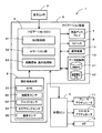
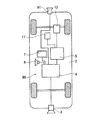
先ず、本実施形態に係る運転支援装置1の概略構成について図1を用いて説明する。図1は本実施形態に係る運転支援装置1の概略構成図である。
図1に示すように、本実施形態に係る運転支援装置1は、車両2に対して設置された後方カメラ(撮像手段)3、ナビゲーション装置4、車両ECU(車両制御手段)5等で構成されている。
DETAILED DESCRIPTION Hereinafter, a driving assistance apparatus according to the present invention will be described in detail with reference to the drawings based on an embodiment that is embodied.
First, a schematic configuration of the driving
As shown in FIG. 1, the driving
後方カメラ3は、例えばCCD等の固体撮像素子を用いたものであり、車両2の後方に装着されたナンバープレートの上中央付近に取り付けられ、視線方向を水平より45度下方に向けて設置される。そして、駐車時に車両2の進行方向となる車両後方を撮像し、その撮像した画像(以下、BGM(バック・ガイド・モニタ)画像とする)はナビゲーション装置の液晶ディスプレイ7に表示される。一方、通常走行中においては、後述のように車両2の周囲の路面上に形成された停止線、横断歩道、文字列、車両の最高速度等の路面標示を撮像する。そして、撮像された路面標示の画像に基づいて車両2から停止線や交差点、合流帯、カーブ進入口等の車両の制御を行う対象となる制御対象物までの距離が間接的に算出される。
The
また、ナビゲーション装置4は、ナビゲーションECU(エレクトロニック・コントロール・ユニット)6と、車両2の室内のセンターコンソール又はパネル面に備え付けられ、地図や目的地までの探索経路を表示する液晶ディスプレイ(走行案内手段)7と、経路案内に関する音声ガイダンスを出力するスピーカ(走行案内手段)8と、車両2の現在地と進行方向を地図上で特定する現在地検出部9と、地図を表示するための地図データや路面上に形成された路面標示の種類及び位置に関する情報が記憶されたデータ記録部10と、情報センタ等と通信を行う為の通信装置14とから構成されている。
The
ナビゲーションECU(路面標示検出手段、物間距離取得手段、対象距離算出手段、運転補助手段、対象物数判定手段、道なり判定手段、誘導経路設定手段、誘導経路判定手段)6は、通常の経路探索及び経路案内の処理の他に、後方カメラ3で撮像した撮像画像から車両2が走行する路面に形成された路面標識を検出する検出処理、一定条件を満たした場合に車両2から停止線や交差点、合流帯、カーブ進入口等の制御対象物までの道なり距離を、検出した路面標示から間接的に算出する算出処理、算出された距離に基づいて制御対象物に対する注意喚起や車両制御処理等を行う電子制御ユニットである。尚、ナビゲーションECU6の詳細な構成については後述する。
The navigation ECU (road marking detection means, object distance acquisition means, object distance calculation means, driving assistance means, object number determination means, road direction determination means, guidance route setting means, guidance route determination means) 6 is a normal route In addition to search and route guidance processing, detection processing for detecting road markings formed on the road surface on which the
そして、車両ECU5は、エンジン、変速機、アクセル、ブレーキ等の作動を制御する車両2の電子制御ユニットであり、ブレーキアクチュエータ11、アクセルアクチュエータ12、AT(Automatic Transmission)13が接続されている。そして、ナビゲーションECU6は、所定の条件を満たした場合に車両ECU5を介してブレーキアクチュエータ11、アクセルアクチュエータ12、AT13に制御信号を送信し、ブレーキ圧やエンジンに吸入する空気量や変速比を変化させ、制動力を自動で付与させる。
The
次に、本実施形態に係る運転支援装置1の制御系に係る構成について特にナビゲーション装置4を中心にして図2に基づき説明する。図2は本実施形態に係る運転支援装置1の制御系を模式的に示すブロック図である。
図2において、運転支援装置1の制御系は、ナビゲーション装置4と、車両ECU5を基本にして構成され、各制御手段に対して所定の周辺機器が接続されている。
Next, the configuration related to the control system of the driving
In FIG. 2, the control system of the driving
以下に、ナビゲーション装置4を構成する各構成要素について説明すると、現在地検出部9は、GPS31、地磁気センサ32、ジャイロセンサ33、ステアリングセンサ34、速度センサ35、高度計(図示せず)等からなり、自車の現在地、方位、自車速度、所定地点からの走行距離等を検出することが可能となっている。
Hereinafter, each component constituting the
具体的には、GPS31は、人工衛星によって発生させられた電波を受信することにより、地球上における自車の現在地及び現在時刻を検出する。
また、地磁気センサ32は、地磁気を測定することによって自車方位を検出する。
そして、ジャイロセンサ33は自車の旋回角を検出する。また、ジャイロセンサ33によって検出された旋回角を積分することにより、自車方位を検出することができる。
また、ステアリングセンサ34は、ステアリング装置の内部に取り付けられており、ステアリングの回動角を検出する。
更に、速度センサ35はエンジンから一定走行距離毎に発生される車速パルスに基づいて、自車速度や移動速度(積算移動距離)を検出する。
Specifically, the
The
And the
The
Furthermore, the
また、データ記録部10は、外部記憶装置及び記録媒体としてのハードディスク(図示せず)と、ハードディスクに記録された所定のプログラム、ナビゲーション装置4の経路案内及び地図表示に必要な情報が格納された地図DB41、路面標示に関する情報が格納された路面標示DB(標示情報記憶手段)42等を読み出すとともにハードディスクに所定のデータを書き込む為のドライバである記録ヘッド(図示せず)とを備えている。
Further, the
ここで、地図DB41は、ナビゲーション装置4の経路案内及び地図表示に必要な地図情報が記録されたDBである。そして、地図情報としては、例えば、地図を表示するための地図データ、各交差点に関する交差点データ、ノード点に関するノードデータ、道路に関する道路データ、経路を探索するための探索データ、施設に関する施設データ、地点を検索するための検索データ等がある。
Here, the
一方、路面標示DB42は、路面上に形成された路面標示に関する路面表示情報が記憶されたDBである。そして、路面表示情報としては、路面上に形成された路面標示の種類(例えば、停止線、横断歩道、文字列、最高速度)に関する種類情報、検出された路面標示の種類を特定する為の特定情報、路面標示の位置を地図上で特定する座標データ等がある。尚、路面標示DB42については後に図3を用いて詳細に説明する。
On the other hand, the road
また、ナビゲーションECU6は、ナビゲーション装置4の全体の制御を行う演算装置及び制御装置としてのCPUの他に、CPUが各種の演算処理を行うに当たってワーキングメモリとして使用されるとともに、経路が探索されたときの経路データ等が記憶されるRAMや、制御用のプログラムのほか、目的地までの経路の探索、探索した誘導経路の案内を行う経路案内処理プログラム、後方カメラ3で撮像した画像に基づいて所定条件下で車両2から制御対象物(停止線、交差点、合流帯、カーブ進入口等)までの道なり距離(対象距離)を算出し、運転補助を行う後述の運転支援処理プログラム(図12〜図14参照)が記録されたROM等の内部記憶装置を備えている。尚、前記RAM、ROM等としては半導体メモリ、磁気コア等が使用される。そして、演算装置及び制御装置としては、CPUに代えてMPU等を使用することも可能である。
The
また、ナビゲーションECU6には、GUI制御部51、ロケーション部52、経路探索・案内処理部53を備え、後方カメラ3、現在地検出部9、データ記録部10及び各周辺機器から取得した情報に基づいて、各種制御を行う。
The
ここで、GUI制御部51は、地図DB41から読み出した地図データとロケーション部52によって検出された自車の現在地とに基づいて自車周囲の適当な地図画像を液晶ディスプレイ7に表示させるとともに、経路の案内が必要な場合には地図画像に対してアイコンや案内画面、探索経路等を合成して液晶ディスプレイ7に表示させる。
また、ロケーション部52は、現在地検出部9から供給される各情報に基づいて、車両2の現在の絶対位置(緯度・経度)を検出する。更に、検出した現在地と路面標示DB42に格納された情報から車両2の所定範囲(前方30m〜後方20m)内に路面標示が存在するか否かを判定し、存在する場合には、後方カメラ3によって撮像した画像を取り込んで解析処理を行い、路面上の路面標示を検出する。そして、検出された路面標示に対して一の制御対象物のみが対応付けられている場合、又は複数の制御対象物が対応付けられている場合であって路面標示と制御対象物までの物間距離の差が所定距離(例えば5m)以上である場合には、撮像した画像から検出した路面標示と車両2との距離を算出し、更にその距離から路面標示に関連付けられた制御対象物までの距離を算出し、算出した距離に応じてブレーキアクチュエータ11、スロットルアクチュエータ12、AT13を制御して車両2の車両制御の実行、或いは液晶ディスプレイ7及びスピーカ8により制御対象物に対する注意喚起等を行う。
更に、経路探索・案内処理部53は、目的地が設定された場合においてデータ記録部10に記憶されたノード点データや探索データに基づいて現在地から目的地までの経路探索及び誘導経路の設定を行うとともに、設定された誘導経路に従って液晶ディスプレイ7やスピーカ8を用いて経路の案内を行う。
Here, the
The
Further, the route search /
また、前記ナビゲーションECU6には、液晶ディスプレイ7、スピーカ8、通信装置14等の各周辺装置が電気的に接続されている。
The
液晶ディスプレイ7には、操作案内、操作メニュー、キーの案内、現在地から目的地までの誘導経路、誘導経路に沿った案内情報、交通情報、ニュース、天気予報、時刻、メール、テレビ番組、後方カメラ3で撮像したBGM画像等が表示される。
The
また、スピーカ8は、ナビゲーションECU6からの指示に基づいて誘導経路に沿った走行を案内する音声ガイダンスを出力する。更に、本実施形態に係るナビゲーション装置4では、車両2から制御対象物までの対象距離が所定距離となった場合に、液晶ディスプレイ7及びスピーカ8により制御対象物に関する情報提供や注意喚起(例えば、停止線が接近していることの警告等)を行う。
Further, the
そして、通信装置14は、情報センタ、例えば、VICS(登録商標:Vehicle Information and Communication System)センタ等から送信された渋滞情報、規制情報、駐車場情報、交通事故情報、サービスエリアの混雑状況等の各情報から成る交通情報を、道路に沿って配設された電波ビーコン装置、光ビーコン装置等を介して電波ビーコン、光ビーコン等として受信するビーコンレシーバである。また、本実施形態に係るナビゲーション装置4は通信装置14を介して情報センタ(図示せず)に接続し、地図DB41及び路面標示DB42に格納された情報を更新する。
Then, the
次に、図3に基づいてデータ記録部10において路面標示に関する情報が記憶される路面標示DB42について説明する。図3は本実施形態に係る路面標示DB42の記憶領域を示した図である。
Next, the
図3に示すように路面標示DB42の記憶領域は、路面標示の地図データ上における座標(位置)と、路面標示の種類と、路面標示に関連付けられた制御対象物と、路面標示の測定開始点(複数ある場合には制御対象物に最も近い測定開始点)から制御対象物までの道なり距離(物間距離)とから構成されている。
As shown in FIG. 3, the storage area of the
例えば、図3では座標(x1,y1)には「横断歩道有り」の路面標示が形成されており、且つその路面標示には60m前方に制御対象物として「停止線」の路面標示が対応付けられていることを示す。
また、座標(x2,y2)には「矢印」の路面標示が形成されており、且つその路面標示には54m前方に制御対象物として「コーナ(コーナ開始点のノード)」が対応付けられていることを示す。
また、座標(x3,y3)には「最高速度(40km/h)」の路面標示が形成されており、且つその路面標示には112m前方に第1の制御対象物として「停止線」が対応付けられ、72m前方に第2の制御対象物として「停止線」が対応付けられていることを示す。
また、座標(x4,y4)には「文字列(「この先カーブ」、「とまれ」、「○○方面」等)」の路面標示が形成されており、且つその路面標示には82m前方に第1の制御対象物として「停止線」が対応付けられ、85m前方に第2の制御対象物として「停止線」が対応付けられていることを示す。
また、座標(x5,y5)には「横断歩道」の路面標示が形成されており、且つその路面標示には108m前方に制御対象物として「交差点(交差点のノード)」が対応付けられていることを示す。尚、路面標示の座標は、路面標示を囲む四角形状の角部に位置する4点の座標から構成される。また、対応付けられる制御対象物の数は3つ以上であっても良い。また、制御対象物までの物間距離に関して、道路が複数車線からなる場合においては、車線毎の制御対象物までの物間距離が記録される。
For example, in FIG. 3, a road marking “with a pedestrian crossing” is formed at coordinates (x1, y1), and the road marking is associated with a road marking “stop line” as a
In addition, a road marking of “arrow” is formed at the coordinates (x2, y2), and “corner (node of corner start point)” is associated with the road marking as a
Further, a road marking of “maximum speed (40 km / h)” is formed at the coordinates (x3, y3), and “stop line” corresponds to the road marking as the
In addition, a road marking of “character string (“ curve ahead ”,“ tore ”,“ XX direction ”, etc.)” is formed at the coordinates (x4, y4), and the road marking is 82 m ahead of the road marking. The “stop line” is associated with the first control object, and the “stop line” is associated with the second control object in front of 85 m.
Further, a road marking “pedestrian crossing” is formed at the coordinates (x5, y5), and “crossing (intersection node)” is associated with the road marking as a
ここで、制御対象物は案内や車両の制御を行う対象となるものであり、路面標示が形成された道路の進行方向であって、所定区間(例えば、10m〜200m)にあるノード点や他の路面標示が相当する。そして、ナビゲーションECU6は後方カメラ3が路面標示DB42に記録されたいずれかの路面標示を撮像した際に、撮像した画像から関連付けられた制御対象物に対しての道なり距離である対象距離を間接的に算出し、その対象距離が所定距離となった場合に車両2の車両制御や制御対象物に対する案内を行う。
Here, the control object is a target for guidance and vehicle control, and is a traveling direction of the road on which the road marking is formed, and is a node point or other in a predetermined section (for example, 10 m to 200 m). The road marking is equivalent. When the
また、車両2の車両制御や案内の内容は関連付けられた制御対象物の種類や制御レベルによって異なる。
ここで、制御レベルとは車両状況や運転者状況によって制御対象物に対する車両制御及び案内の必要度合いを複数段階に分けて判定したものである。具体的には、制御対象物に接近した状態で十分な減速制御が行われていない場合には制御レベルが高いと判定され、既に十分な減速制御が行われている場合には制御レベルが低いと判定される。本実施形態では、特に制御対象物との対象距離が所定距離(例えば、制御対象物が停止線やカーブの場合は50m)となった時点で、制御対象物に対する必要減速度(車両にかかる減速G)G1を自車の現在速度や加速度から算出する。そして、算出された必要減速度の値から制御レベルを判定し、車両制御や案内の内容を選択する。尚、図4は各制御レベルで実施される制御対象物に対する車両制御と案内の内容の一覧を示した図である。
Further, the contents of vehicle control and guidance of the
Here, the control level is determined by dividing the degree of necessity of vehicle control and guidance for the control target according to the vehicle situation and the driver situation in a plurality of stages. Specifically, the control level is determined to be high when sufficient deceleration control is not performed while being close to the control object, and the control level is low when sufficient deceleration control is already performed. It is determined. In the present embodiment, particularly when the target distance to the control object reaches a predetermined distance (for example, 50 m when the control object is a stop line or a curve), the necessary deceleration (deceleration applied to the vehicle) with respect to the control object. G) G1 is calculated from the current speed and acceleration of the vehicle. Then, the control level is determined from the calculated required deceleration value, and the contents of vehicle control and guidance are selected. FIG. 4 is a diagram showing a list of the contents of vehicle control and guidance for the control object executed at each control level.
図4に示すように、(1)算出された必要減速度G1<0.05Gである場合には制御レベル「無し」と判定し、制御及び案内は実施しない。
また、(2)0.05G≦G1<0.1Gである場合には制御レベル「低」と判定し、情報提供レベルの案内のみを実施する。例えば、制御対象物として「停止線」又は「コーナ」が対応付けられていた場合には、停止線又はコーナが接近していることを報知する停止線又はコーナのマークを液晶ディスプレイ7に表示させる。
また、(3)0.1G≦G1<0.3Gである場合には制御レベル「中」と判定し、注意喚起レベルの案内のみを実施する。例えば、制御対象物として「停止線」又は「コーナ」が対応付けられていた場合には、制御対象物が接近していることを警告する「停止線(コーナ)が接近しています。」との文字列を液晶ディスプレイ7に表示させ、またスピーカ8から同内容の警告音声を出力する。
更に、(4)0.3G<G1である場合には制御レベル「高」と判定し、サポート、介入レベルの車両制御及び案内を実施する。例えば、制御対象物として「停止線」又は「コーナ」が対応付けられていた場合には、停止線が接近していることを警告する「停止線(コーナ)が接近しています。」との文字列を液晶ディスプレイ7に表示させ、またスピーカ8から同内容の警告音声を出力する。更に、制御対象物が「停止線」である場合にはブレーキアクチュエータ11やAT13を制御して停止線の手前で車両2が停止するように減速制御を行う。一方、制御対象物が「コーナ」である場合、コーナ進入前に地図DB41に記録されたコーナのRに対する最適な速度(例えば、R30で40km/h)となるようにブレーキアクチュエータ11やAT13を制御して減速制御を行う。
As shown in FIG. 4, (1) if the calculated required deceleration G1 <0.05G, it is determined that the control level is “none”, and control and guidance are not performed.
(2) When 0.05G ≦ G1 <0.1G, it is determined that the control level is “low”, and only the information providing level guidance is performed. For example, when “stop line” or “corner” is associated as the control object, a stop line or corner mark for notifying that the stop line or corner is approaching is displayed on the
(3) When 0.1G ≦ G1 <0.3G, it is determined that the control level is “medium”, and only guidance for the alert level is performed. For example, if “stop line” or “corner” is associated as a control object, “a stop line (corner) is approaching” that warns that the control object is approaching. Is displayed on the
Further, (4) when 0.3G <G1, it is determined that the control level is “high”, and support and intervention level vehicle control and guidance are performed. For example, when “stop line” or “corner” is associated as a control object, “stop line (corner) is approaching” that warns that the stop line is approaching. The character string is displayed on the
尚、制御対象物として「交差点」が対応付けられていた場合には、車両制御を行わずに制御対象物との対象距離が所定距離(例えば10m)となった時点で、設定された誘導経路に従った経路案内のみを行う。例えば、左折を示す案内表示を液晶ディスプレイ7に表示させ、「次の交差点を左折して下さい。」の案内音声をスピーカ8から出力する。
In the case where “intersection” is associated as the control object, the set guidance route is set when the target distance to the control object becomes a predetermined distance (for example, 10 m) without performing vehicle control. Follow route guidance only. For example, a guidance display indicating a left turn is displayed on the
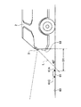
次に、図5乃至図9を用いて車両2の後方カメラ3によって路面標示を撮像した際の車両2と路面標示との距離、及び車両2と路面標示に関連付けられた制御対象物との距離の算出方法について具体例をあげて説明する。
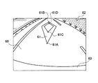
以下の具体例では、車両2が走行する路面60に形成された路面標示の内、特に制御対象物として停止線の路面標示69が関連付けられた「横断歩道有り」の路面標示61を撮像した場合を示すこととする。図5は路面標示61を撮像する車両2を示した上面図、図6は路面標示61を撮像する車両2を示した側面図、図7は図5及び図6の状態における車両2の後方カメラ3によって撮像された撮像画像62を示した模式図である。
Next, the distance between the
In the following specific example, when a road marking 61 “with a pedestrian crossing” associated with a road marking 69 of a stop line as a control object is captured among road markings formed on the
後方カメラ3は、図6に示すように車両2の後バンパー63付近から後方を撮像できるように光軸Lを水平から45度下方向に向けるように取り付けられており、撮像範囲が固定されている。従って、後方カメラ3によって撮像された図7に示す撮像画像中の画像データの位置(具体的には下縁からの画素数)から、被写体までの距離を計算することができる。
As shown in FIG. 6, the
ここで、路面標示には車両2との距離を計測する為の測定開始点が予め複数箇所に定義されており、車両2から最も進行方向側にある測定開始点までの距離を車両2から路面標示までの距離として扱う。例えば、図8(A)は「横断歩道有り」の路面標示61の測定開始点61A〜61Dを示した模式図、図8(B)は「最高速度(20km/h)」の路面標示65の測定開始点65A〜65Dを示した模式図である。
図8(A)及び図8(B)に示すように、路面標示の測定開始点は路面標示を形成するライン(境界線)の角部や先端部に複数個設けられており、路面標識毎に特有の配置を有する。そして、ナビゲーションECU6は路面標示を撮像した際に、その撮像した路面標示の画像から路面標示の境界線や測定開始点を特定することにより、路面標示の種類を判定することが可能となる。
Here, a plurality of measurement start points for measuring the distance to the
As shown in FIG. 8 (A) and FIG. 8 (B), a plurality of road marking start points are provided at the corners and tips of lines (boundary lines) forming the road marking. Has a unique arrangement. Then, when the
また、図7に示す路面標示を撮像した撮像画像中において、測定開始点の位置(具体的には下縁から測定開始点までの画素数)から車両2と測定開始点の間の距離D1を算出することが可能となる。ここで、複数ある測定開始点の内、いずれの測定開始点との間の距離を算出するかは、路面標示ごとに決まっており、例えば、図8(A)に示す「横断歩道有り」の路面標示61では測定開始点61Aとの距離が算出される。但し、測定開始点61Aが何らかの原因(例えば、砂や水溜り等の障害物によって白線の一部が隠れた状態や、長年の使用による劣化によって白線の一部で塗装が剥がれている場合)によって特定できなかった場合には、先ず測定開始点61Bまでの距離を算出し、その後に測定開始点61Aと測定開始点61Bとの距離を用いることによって測定開始点61Aとの距離が間接的に算出される。更に、測定開始点61Bについても特定できなかった場合には測定開始点61Cが用いられ、測定開始点61Cについても特定できなかった場合には測定開始点61Dが用いられる。
Further, in the captured image obtained by capturing the road marking shown in FIG. 7, the distance D1 between the
また、図8(B)に示す「最高速度(20km/h)」の路面標示65では測定開始点65A及び測定開始点65Bとの距離が算出される。但し、測定開始点65A及び測定開始点65Bが何らかの原因(例えば、砂や水溜り等の障害物によって白線の一部が隠れた状態や、長年の使用による劣化によって白線の一部で塗装が剥がれている場合)によって特定できなかった場合には、測定開始点65C及び測定開始点65Dを用いることによって測定開始点65A及び測定開始点65Bとの距離が間接的に算出される。
Further, in the road marking 65 of “maximum speed (20 km / h)” shown in FIG. 8B, the distance between the
一方、前記した方法によって車両2と路面標示の測定開始点までの距離D1が算出されると、それに基づいて車両2から検出された路面標示に関連付けられた制御対象物(図3参照)までの道なり距離(対象距離)を算出することが可能である。図9は、車両2の後方カメラ3によって路面標示を撮像した際の車両2から制御対象物までの対象距離の算出方法について示した模式図である。
On the other hand, when the distance D1 between the
図9では、「横断歩道有り」の路面標示61を車両2が後方カメラ3で検出した場合を示すものであり、更に、路面標示61には制御対象物として前方の物間距離Mにある「停止線」の路面標示69が関連付けられている。
その場合には、物間距離Mから距離D1及び車両長さD2を減算することによって、路面標示61の検出時点での車両2から制御対象物までの対象距離T(=M−D1−D2)を算出することが可能となる。また、ナビゲーションECU6はエンジンから一定走行距離毎に発生される車速パルスに基づいて速度センサ35により車両2の走行距離Sを算出する。そして、路面標示61の検出時点での車両2から制御対象物までの対象距離Tから走行距離Sを減算することによって、走行中の車両2から制御対象物までの対象距離T(=M−D1−D2−S)を算出することが可能となる。その結果、算出された「停止線」の路面標示69までの対象距離Tに基づいて車両の制御及び案内を行う。
FIG. 9 shows a case in which the
In that case, by subtracting the distance D1 and the vehicle length D2 from the distance M between the objects, the target distance T (= M−D1−D2) from the
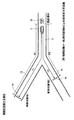
次に、特に車両2が後方カメラ3で検出した路面標示に関連付けられた制御対象物が複数ある場合において、制御対象物に対する案内及び車両制御の実施の態様について図10及び図11について説明する。
図10及び図11では、分岐を有する道路71を車両2が走行する場合であって、道路71の路面に形成された最高速度が40km/hであることを示す路面標示72に対して、一方の第1分岐道路73の路面に形成された第1停止線74と他方の第2分岐道路75の路面に形成された第2停止線76の2つの制御対象物が関連付けられている。この場合には、分岐点を通過する前には車両2がその後の道路分岐においていずれの道路に進入するか特定できない。従って、分岐点を通過する前においては、第1停止線74を対象とした案内や車両制御と、第2停止線76を対象とした案内や車両制御のどちらを行うべきかが問題となる。
Next, in the case where there are a plurality of control objects associated with the road markings detected by the
10 and 11, when the
ここで、本実施形態に係る運転支援装置1では、分岐点を通過するまでは車両2による走行距離が短い方の制御対象物を対象とした注意喚起や車両制御を行うこととする。従って、路面標示DB42(図3参照)に記憶された各制御対象物までの物間距離を比較して、分岐点を通過するまでは物間距離が短い方の制御対象物を対象とした案内や車両制御を行う。しかしながら、両者の物間距離の差がほとんど無い場合には、車両2が各制御対象物まで走行するのに必要な走行距離が短い方の制御対象物を特定することができないので、その場合には分岐点を通過するまでは、制御対象物を対象とした案内や車両制御を行わないようにする。
Here, in the driving
具体的には、図10及び図11に示すように、車両2が後方カメラによって走行中に路面標示72を検出すると、路面標示DB42から路面標示72から第1停止線74までの物間距離である第1物間距離M1と路面標示72から第2停止線76までの物間距離である第2物間距離M2を取得し、距離差を算出する。
Specifically, as shown in FIGS. 10 and 11, when the road marking 72 is detected while the
その結果、図10に示すように第1物間距離M1と第2物間距離M2との差が制御実施可否距離(例えば5m)以上である場合には、車両2が各制御対象物まで走行するのに必要な走行距離が短い方の制御対象物(図10では第2停止線76)を正確に特定することができる。従って、分岐点を通過するまでは第2停止線76を対象とし、車両2から第2停止線76までの距離である第2対象距離T2に基づいて案内や車両制御を行う。また、分岐点を通過した後は、車両が走行する道路にある制御対象物を対象とした案内や車両制御を行う。即ち、車両2が分岐点で第1分岐道路73に進入した場合には、その後は第1停止線74を対象とし、車両2から第1停止線74までの距離である第1対象距離T1に基づいて案内や車両制御を行う。一方、車両2が分岐点で第2分岐道路75に進入した場合には、継続して第2停止線76を対象とした案内や車両制御を行う。
As a result, as shown in FIG. 10, when the difference between the first object distance M1 and the second object distance M2 is equal to or greater than the control feasibility distance (for example, 5 m), the
それに対して、図11に示すように第1物間距離M1と第2物間距離M2との差が制御実施可否距離(例えば5m)未満である場合には、車両2が各制御対象物まで走行するのに必要な走行距離が短い方の制御対象物を正確に特定することができない。従って、分岐点を通過するまでは第1停止線74及び第2停止線76のいずれに対しても、制御対象物を対象とした案内や車両制御は行わない。但し、分岐点を通過した後は、図10と同様にして車両が走行する道路にある制御対象物を対象とした案内や車両制御を行う。即ち、車両2が分岐点で第1分岐道路73に進入した場合には、その後は第1停止線74を対象とし、車両2から第1停止線74までの距離である第1対象距離T1に基づいて案内や車両制御を行う。一方、車両2が分岐点で第2分岐道路75に進入した場合には、継続して第2停止線76を対象とした案内や車両制御を行う。
On the other hand, as shown in FIG. 11, when the difference between the first object distance M1 and the second object distance M2 is less than the control feasibility distance (for example, 5 m), the
尚、路面標示や制御対象物の形成された道路がカーブ形状を有している場合には、カーブ形状に沿って対象距離が算出される。また、路面標示や制御対象物の形成された道路が登り坂や下り坂である場合には、坂の勾配に沿って対象距離が算出される。 When the road on which road markings and control objects are formed has a curve shape, the target distance is calculated along the curve shape. Further, when the road on which the road marking and the control target are formed is an uphill or downhill, the target distance is calculated along the slope of the slope.
以上のように、直接制御対象物を認識することなく、後方カメラ3によって検出された路面標示から前方にある制御対象物までの対象距離を間接的に算出することにより、より早い段階で正確な制御対象物までの対象距離(T=M−D1−D2−S)を算出することが可能となる。そして、算出された正確な制御対象物までの対象距離に基づいて適切な車両の制御や、より的確なタイミングでの走行案内が可能となる。
As described above, by directly calculating the target distance from the road marking detected by the
続いて、前記構成を有する本実施形態に係る運転支援装置1のナビゲーションECU6が実行する運転支援処理プログラムについて図12及び図13に基づき説明する。図12及び図13は本実施形態に係る運転支援装置1における運転支援処理プログラムのフローチャートである。ここで、運転支援処理プログラムは車両のイグニションがONされた後に所定間隔(例えば200ms毎)で実行され、車両2が路面を走行する際において後方カメラ3により撮像した撮像画像から路面標示を検出するとともに、所定条件を満たした場合に検出した路面標示から車両と制御対象物までの対象距離を算出し、算出された対象距離に基づいて利用者の運転を補助する制御を行うプログラムである。尚、以下の図12乃至図14にフローチャートで示されるプログラムはナビゲーションECU6が備えているROMやRAMに記憶されており、CPUにより実行される。
Next, a driving assistance processing program executed by the
運転支援処理プログラムでは、先ずステップ(以下、Sと略記する)1において、ナビゲーションECU6は現在地検出部9によって検出した車両2の現在地情報と路面標示DB42(図3参照)に記録された路面標示の位置情報に基づいて、車両2の周辺(本実施形態では車両2の前方2000m〜後方500m)に位置する路面標示の情報(路面標示の位置座標、種類、関連付けられた制御対象物、制御対象物までの物間距離)を路面標示DB42から読み出す。尚、上記S1が物間距離取得手段の処理に相当する。
In the driving support processing program, first, in step (hereinafter abbreviated as S) 1, the
次に、S2でナビゲーションECU6は、前記S1で読み出された路面標示の内、特に車両2の所定範囲(車両2の前方30m〜後方20m)に位置する路面標示があるか否かを判定する。そして、車両2の所定範囲に位置する路面標示があると判定された場合(S2:YES)には、S3へと移行し、路面標示の画像認識処理を行う。一方、車両2の所定範囲に位置する路面標示がないと判定された場合(S2:NO)には、当該運転支援処理プログラムを終了し、所定時間経過後に再度、現在地点に基づく路面標示の情報の読み出しを行う。
Next, in S2, the
S3の路面標示の画像認識処理では、後方カメラ3によって撮像される車両2の後方環境の画像を取り込んで解析処理を行い、車両が走行する路面上に形成された路面標示の境界線や測定開始点を特定するとともに、検出された路面標示の種類を判定する。
具体的には、先ず、NTSCのようなアナログ通信手段や、i−linkのようなデジタル通信手段を用いて後方カメラ3で撮像した映像を入力し、jpeg、mpeg等のデジタル画像フォーマットに変換する。次に、路面標示が一般に白線又は黄線であることを用いて、撮像画像中の路面標示が描かれた路面と他の路面を輝度差に基づいて輝度補正を行う。その後、対象となる路面標示を画像から分離する2値化処理、歪みを補正する幾何学処理、画像の雑音を除去する平滑化処理等を行い、路面標示と他の路面との境界線及び測定開始点を検出する。
その後、検出された境界線及び測定開始点の配置から撮像画像中の路面標示の種類を特定し、更には特定された路面標示の種類が前記S2で自車の所定範囲に存在すると判定された路面標示の種類と一致するか否かを判定する。尚、上記S3が路面標示検出手段の処理に相当する。
In the image recognition processing of the road marking in S3, the image of the rear environment of the
Specifically, first, an image captured by the
Thereafter, the type of the road marking in the captured image is specified from the detected boundary line and the arrangement of the measurement start point, and it is further determined that the specified road marking type is present in the predetermined range of the own vehicle in S2. It is determined whether or not it matches the type of road marking. Note that S3 corresponds to the process of the road marking detection means.
そして、S4では前記S3の処理で路面標示が検出されたか否かが判定され、路面標示が検出されたと判定された場合(S4:YES)、即ち、撮像された撮像画像中に路面標示を認識し、且つ、認識された路面標示が前記S2で自車の周囲に位置すると判定された路面標示の種類と一致すると判定された場合には、S5へと移行する。一方、路面標示が検出されなかったと判定された場合(S4:NO)、即ち、撮像された撮像画像中に路面標示が認識できなかったか、又は、認識された路面標示が前記S2で自車の周囲に位置すると判定された路面標示の種類と一致しないと判定された場合には、当該運転支援処理プログラムを終了し、所定時間経過後に再度、現在地点に基づく路面標示の情報の読み出しを行う。 In S4, it is determined whether or not a road marking has been detected in the process of S3. If it is determined that a road marking has been detected (S4: YES), that is, the road marking is recognized in the captured image. If it is determined that the recognized road marking matches the type of road marking determined to be located around the vehicle in S2, the process proceeds to S5. On the other hand, if it is determined that the road marking has not been detected (S4: NO), that is, the road marking has not been recognized in the captured image, or the recognized road marking has been If it is determined that it does not match the type of road marking determined to be located in the vicinity, the driving support processing program is terminated, and the road marking information based on the current location is read again after a predetermined time.
続いて、S5でナビゲーションECU6は車両2が現在走行する周辺の道路に関する道路情報を地図DB41から取得する。
Subsequently, in S5, the
更に、S6においてナビゲーションECU6は前記S5で取得した道路情報から、車両2の進行方向に分岐があるか否か判定する。尚、上記S6が分岐判定手段の処理に相当する。
Further, in S6, the
そして、車両2の進行方向に分岐があると判定された場合(S6:YES)には、更に、前記S1で取得した路面標示情報に基づいて前記S3で検出した路面標示に対して複数の制御対象物が対応付けられているか否か、即ち分岐後の複数の道路に対して少なくとも2以上の制御対象物が存在するか否か判定される(S7)。尚、上記S7が対象物数判定手段の処理に相当する。 When it is determined that there is a branch in the traveling direction of the vehicle 2 (S6: YES), a plurality of controls are further performed on the road marking detected in S3 based on the road marking information acquired in S1. It is determined whether or not the objects are associated, that is, whether or not there are at least two or more control objects for the plurality of roads after branching (S7). Note that S7 corresponds to the processing of the object number determination means.
そして、前記S3で検出した路面標示に対して複数の制御対象物が対応付けられていると判定された場合(S7:YES)には、更に、前記S5で取得した道路情報に基づいて車両2が現在走行する道路と分岐後のいずれか一の道路が道なりの関係にある道なり情報があるか否か、及び、分岐後のいずれか一の道路が誘導経路に設定されているか否か判定される(S8)。尚、上記S8が道なり判定手段及び誘導経路判定手段の処理に相当する。
If it is determined that a plurality of control objects are associated with the road marking detected in S3 (S7: YES), the
その結果、道なり情報も誘導経路の設定も無いと判定された場合(S8:NO)には、S9へと移行する。
一方、前記S6において車両2の進行方向に分岐が無いと判定された場合(S6:NO)及び前記S7において路面標示に対して単一の制御対象物のみが対応付けられていると判定された場合(S7:NO)には、検出された路面標示に関連付けられた制御対象物を対象とした案内や車両制御を行う(S10)。尚、S10での制御対象物に対する案内や車両制御の具体的処理の内容については、後に図14を用いて詳細に説明する。
As a result, when it is determined that there is no road information or guidance route setting (S8: NO), the process proceeds to S9.
On the other hand, when it is determined in S6 that there is no branch in the traveling direction of the vehicle 2 (S6: NO), it is determined in S7 that only a single control object is associated with the road marking. In the case (S7: NO), guidance and vehicle control are performed for the control object associated with the detected road marking (S10). Note that the details of the specific processing of guidance and vehicle control for the controlled object in S10 will be described later in detail with reference to FIG.
また、前記S8において道なり情報及び誘導経路の設定のいずれかが有ると判定された場合(S8:YES)には、道なりの関係がある分岐後の道路又は誘導経路に設定された分岐後の道路に存在する制御対象物を選択し(S11)、選択された制御対象物を対象とした後述の案内や車両制御を行う(S10)。 Further, when it is determined in S8 that there is either road information or a guidance route setting (S8: YES), after a branch set on a road or a guidance route after a branch having a road relationship A control object existing on the road is selected (S11), and guidance and vehicle control described later are performed for the selected control object (S10).
次に、S9でナビゲーションECU6は前記S3で検出された路面標示に関連付けられた複数の制御対象物について、それぞれの路面標示からの物間距離の差を算出する。尚、3つ以上の制御対象物が対応付けられている場合には、物間距離の差が最も最も短くなる2つの制御対象物を対象とした物間距離の差を算出する。その後、S12へと移行する。
Next, in S9, the
S12でナビゲーションECU6は、車両の進行方向にある分岐を越えたか否か判定する。そして、分岐を越えたと判定された場合(S12:YES)には、車両進行方向の分岐後の道路に存在する制御対象物を選択し(S13)、選択された制御対象物を対象とした後述の案内や車両制御を行う(S16)。
In S12, the
一方、分岐を越えていないと判定された場合(S12:NO)には、前記S9で算出した物間距離の差が制御実施可否距離(例えば5m)以上であるか否か判定される(S14)。その結果、物間距離の差が制御実施可否距離以上であると判定された場合(S14:YES)には、車両2が各制御対象物まで走行するのに必要な走行距離が短い方の制御対象物を特定することが可能であり、S15へと移行する。
On the other hand, when it is determined that the branch is not exceeded (S12: NO), it is determined whether or not the difference between the object distances calculated in S9 is equal to or greater than the control feasibility distance (for example, 5 m) (S14). ). As a result, when it is determined that the difference between the distances between objects is equal to or greater than the control feasibility distance (S14: YES), the control with the shorter travel distance required for the
S15でナビゲーションECU6は検出された路面標示に関連付けられた複数の制御対象物の内、最も物間距離が短い制御対象物を選択し(S15)、選択された制御対象物を対象とした後述の案内や車両制御を行う(S16)。
In S15, the
それに対して、物間距離の差が制御実施可否距離未満であると判定された場合(S14:NO)には、車両2が各制御対象物まで走行するのに必要な走行距離が短い方の制御対象物を特定することができないので、その場合には分岐点を通過するまでは、制御対象物を対象とした案内や車両制御を行わないようにする。
On the other hand, when it is determined that the difference in distance between objects is less than the control feasibility distance (S14: NO), the shorter travel distance required for the
次に、前記S10及びS16で実行される案内及び車両制御処理について図14に基づき説明する。図14は本実施形態に係る運転支援装置1における案内及び車両制御処理のフローチャートである。
Next, the guidance and vehicle control processing executed in S10 and S16 will be described with reference to FIG. FIG. 14 is a flowchart of guidance and vehicle control processing in the driving
先ず、S21でナビゲーションECU6は前記S3で検出された路面標示と車両2との間の距離を算出する。具体的には、路面標示を撮像した撮像画像(図7参照)中における特定された測定開始点の位置(具体的には下縁から測定開始点までの画素数)から、車両2と測定開始点の間の距離D1を算出する。
First, in S21, the
その後、S22でナビゲーションECU6は、前記S21で算出された車両2と測定開始点の間の距離D1と、路面標示から案内及び車両制御の対象に選択された制御対象物までの物間距離Mと、車両長さD2とから、路面標示検出時点の車両2から制御対象物までの対象距離T(=M−D1−D2)を算出する(図9参照)。
更に、S22ではエンジンから一定走行距離毎に発生される車速パルスに基づいて速度センサ35により路面標示検出地点からの車両2の走行距離Sを算出し、走行中の車両2の現在位置から制御対象物までの対象距離T(=M−D1−D2−S)を算出する(図9参照)。尚、上記S21及びS22が対象物距離算出手段の処理に相当する。
Thereafter, in S22, the
Further, in S22, the travel distance S of the
その後、S23では前記S22で算出された制御対象物までの対象距離Tに基づいて、車両2が制御対象物の種類ごとに設定された案内又は制御開始地点に到達したか否かが判定される。例えば、制御対象物が「停止線」や「コーナ」である場合には、対象距離が50m以下である場合に、案内又は制御開始地点に到達したと判定される。また、制御対象物が「交差点」の路面標示である場合には残距離が10m以下である場合に、案内又は制御開始地点に到達したと判定される。
Thereafter, in S23, based on the target distance T to the control object calculated in S22, it is determined whether or not the
そして、車両2が案内又は制御開始地点に到達したと判定された場合(S23:YES)には、制御対象物に対する走行の案内又は車両制御が必要か否かを判定する為に車両状況及び運転者状況の取得が行われる(S24)。具体的には、車両2の車速、アクセル開度、ステアリング角、運転者の顔の向き、視線方向等を取得する。
If it is determined that the
そして、S25でナビゲーションECU6は、前記S24で取得した車両状況及び運転者状況に基づいて、制御対象物に対する車両制御及び案内の必要度合いを複数段階に分けて示した制御レベルの算出、判定を行う。
ここで、本実施形態では既に図4に示したように制御対象物に対する必要減速度(車両にかかる減速G)G1を自車の現在速度や加速度から算出し、算出された必要減速度の値から制御レベルを判定する。
In step S25, the
Here, in the present embodiment, as already shown in FIG. 4, the required deceleration (deceleration G applied to the vehicle) G1 for the control object is calculated from the current speed and acceleration of the own vehicle, and the calculated required deceleration value. The control level is determined from the above.
続いて、S26においてナビゲーションECU6は、前記S25で判定された制御レベルに応じた案内及び車両制御を行う。
具体的に、図4に示すように(1)算出された必要減速度G1<0.05Gである場合には制御レベル「無し」と判定され、制御及び案内は実施しない。
また、(2)0.05G≦G1<0.1Gである場合には制御レベル「低」と判定され、情報提供レベルの案内のみを実施する。例えば、制御対象物として「停止線」又は「コーナ」が対応付けられていた場合には、停止線又はコーナが接近していることを報知する停止線又はコーナのマークを液晶ディスプレイ7に表示させる。
また、(3)0.1G≦G1<0.3Gである場合には制御レベル「中」と判定され、注意喚起レベルの案内のみを実施する。例えば、制御対象物として「停止線」又は「コーナ」が対応付けられていた場合には、停止線が接近していることを警告する「停止線(コーナ)が接近しています。」との文字列を液晶ディスプレイ7に表示させ、またスピーカ8から同内容の警告音声を出力する。
更に、(4)0.3G<G1である場合には制御レベル「高」と判定され、サポート、介入レベルの車両制御及び案内を実施する。例えば、制御対象物として「停止線」又は「コーナ」が対応付けられていた場合には、停止線が接近していることを警告する「停止線(コーナ)が接近しています。」との文字列を液晶ディスプレイ7に表示させ、またスピーカ8から同内容の警告音声を出力する。更に、制御対象物が「停止線」である場合にはブレーキアクチュエータ11やAT13を制御して停止線の手前で車両2が停止するように減速制御を行う。一方、制御対象物が「コーナ」である場合、コーナ進入前に地図DB41に記録されたコーナのRに対する最適な速度(例えば、R30で40km/h)となるようにブレーキアクチュエータ11やAT13を制御して減速制御を行う。
尚、制御対象物として「交差点」が対応付けられていた場合には、車両制御を行わずに制御対象物との対象距離が所定距離(例えば10m)となった時点で、設定された誘導経路に従った経路案内のみを行う。例えば、左折を示す案内表示を液晶ディスプレイ7に表示させ、「次の交差点を左折して下さい。」の案内音声をスピーカ8から出力する。
Subsequently, in S26, the
Specifically, as shown in FIG. 4, when (1) calculated required deceleration G1 <0.05G, it is determined that the control level is “none”, and control and guidance are not performed.
Further, (2) if 0.05G ≦ G1 <0.1G, it is determined that the control level is “low”, and only the information providing level guidance is performed. For example, when “stop line” or “corner” is associated as the control object, a stop line or corner mark for notifying that the stop line or corner is approaching is displayed on the
(3) When 0.1G ≦ G1 <0.3G, it is determined that the control level is “medium” and only guidance at the alert level is performed. For example, when “stop line” or “corner” is associated as a control object, “stop line (corner) is approaching” that warns that the stop line is approaching. The character string is displayed on the
Further, (4) when 0.3G <G1, it is determined that the control level is “high”, and support and intervention level vehicle control and guidance are performed. For example, when “stop line” or “corner” is associated as a control object, “stop line (corner) is approaching” that warns that the stop line is approaching. The character string is displayed on the
In the case where “intersection” is associated as the control object, the set guidance route is set when the target distance to the control object becomes a predetermined distance (for example, 10 m) without performing vehicle control. Follow route guidance only. For example, a guidance display indicating a left turn is displayed on the
一方、車両2が案内又は制御開始地点に到達していないと判定された場合(S23:NO)には、制御対象物に対する案内及び車両制御を行うことなく処理を終了する。尚、上記S26が運転補助手段の処理に相当する。
On the other hand, when it is determined that the
以上詳細に説明した通り、本実施形態に係る運転支援装置1では、車両2から所定範囲内に路面標示が存在すると判定された場合(S2:YES)に、後方カメラ3によって撮像された画像から路面標示を検出し(S3)、検出された路面標示に関連付けられた制御対象物が単数である場合、又は前記関連付けられた制御対象物が複数であって且つそれぞれの物間距離の差が制御実施可否距離以上である場合(S14:YES)に、車両から案内及び車両制御の対象となる制御対象物までの対象距離を算出し(S21、S22)、算出された対象距離に基づいて、制御対象物に応じた案内及び車両制御を行う(S26)ので、車両2が検出した路面標示に対して制御対象物が複数関連付けられた場合であっても、不要な案内や誤制御が行われる虞の有る状況での案内や車両制御を予め行わないことにより、運転者に関連する制御対象物を対象とした注意喚起や車両制御を行うことが可能となる。また、演算処理を行う回数を減らすことにより、ナビゲーションECU6の処理負担についても軽減することが可能となる。
また、分岐の有る道路を車両2が走行する場合であって、車両2が検出した路面標示に対して分岐後の各道路に形成された複数の制御対象物が関連付けられた場合であっても、不要な案内や誤制御が行われる虞の有る状況での案内や車両制御を予め行わないことにより、分岐で車両2が走行する方の道路に形成された制御対象物を対象とした案内や車両制御を行うことが可能となる。
また、分岐の有る道路を車両2が走行する場合であって、車両2が検出した路面標示に対して分岐後の各道路に形成された複数の制御対象物が関連付けられた場合であっても、車両2が分岐に到達する前の不要な案内や誤制御が行われる虞の有る状況では制御対象物に対する案内や車両制御を予め行わないので、運転者を困惑わせる虞が無い。
また、分岐前の道路と分岐後の道路に道なりの関係がある場合(S8:YES)には、道なりの関係にある分岐後の道路を車両が走行する道路と予測し、車両が走行すると予測される道路に形成された制御対象物を対象とした注意喚起や車両制御を行うので、不要な案内や誤制御が行われることを防止することができる。
また、分岐後の道路が誘導経路に設定されている場合(S8:YES)には、誘導経路に設定されている分岐後の道路を車両が走行する道路と予測し、車両が走行すると予測される道路に形成された制御対象物を対象とした注意喚起や車両制御を行うので、同じく不要な案内や誤制御が行われることを防止することができる。
更に、車両から制御対象物までの対象距離に基づいて案内や車両の制御を行うので、遠方を撮像する為にフロントカメラによる撮像装置等の高額な装置を必要とすることなく、確実に制御対象物の種類の応じた案内や車両の制御を行うことが可能となる。
As described above in detail, in the driving
Further, even when the
Further, even when the
If the road before the branch and the road after the branch have a road-like relationship (S8: YES), the road after the branch having the road-like relationship is predicted as a road on which the vehicle travels, and the vehicle travels. Then, since alerting and vehicle control are performed for the control object formed on the predicted road, unnecessary guidance and erroneous control can be prevented.
Further, when the road after the branch is set as the guide route (S8: YES), the road after the branch set as the guide route is predicted as the road on which the vehicle travels, and the vehicle is predicted to travel. Therefore, it is possible to prevent unnecessary guidance and erroneous control from being performed in the same manner.
Furthermore, since guidance and vehicle control are performed based on the target distance from the vehicle to the control object, the control object can be surely controlled without requiring an expensive device such as an imaging device using a front camera to image a distant place. It is possible to perform guidance and vehicle control according to the type of object.
尚、本発明は前記実施形態に限定されるものではなく、本発明の要旨を逸脱しない範囲内で種々の改良、変形が可能であることは勿論である。
例えば、本実施形態では、制御対象物が停止線、交差点、コーナ進入口である場合について説明したが、制御対象物は上記のものに限られること無く、例えば、横断歩道等の路面標示の他、インターチェンジ等の施設であっても良い。
Note that the present invention is not limited to the above-described embodiment, and various improvements and modifications can be made without departing from the scope of the present invention.
For example, in the present embodiment, the case where the control object is a stop line, an intersection, or a corner entrance has been described. However, the control object is not limited to the above, and other than road markings such as pedestrian crossings, for example. It may be a facility such as an interchange.
また、本実施形態では制御対象物に対する必要減速度(車両にかかる減速G)G1を自車の現在速度や加速度から算出し、算出された必要減速度の値から制御レベルを判定することとしているが、運転者の顔の向きや視線方向から制御レベルを判定するようにしても良い。即ち、車両2が案内又は制御開始地点に到達した時点で運転者が前方を見ていない場合に制御レベル「高」と判定し、運転者が前方を見ている場合に制御レベル「無し」と判定するようにしても良い。
In the present embodiment, the required deceleration (deceleration G applied to the vehicle) G1 for the control object is calculated from the current speed and acceleration of the host vehicle, and the control level is determined from the calculated required deceleration value. However, the control level may be determined from the direction of the driver's face and the direction of the line of sight. That is, when the
また、本実施形態に係る運転支援装置1が、撮像手段として後方環境を撮像する後方カメラ3を設け、後方カメラによって撮像した画像に基づいて路面標示の認識を行い、制御対象物に対する制御を行っていたが、撮像手段として後方カメラ3のほかに車両2の前方環境を撮像する前方カメラを設け、後方カメラ3に加えて前方カメラで撮像した画像に基づいて路面標示の認識を行っても良い。
ここで、図15は他の実施形態に係る運転支援装置90の概略構成図である。
図15に示すように、他の実施形態に係る運転支援装置90は、車両2に対して設置された前方カメラ91、後方カメラ3、ナビゲーション装置4、車両ECU5等で構成されている。尚、前方カメラ91以外の後方カメラ3、ナビゲーション装置4、車両ECU5の各構成に関しては前記した本実施形態に係る運転支援装置1と同様であり、その説明は省略する。
In addition, the driving
Here, FIG. 15 is a schematic configuration diagram of a driving
As shown in FIG. 15, the driving
そして、他の実施形態に係る運転支援装置90では前方カメラ91で撮像した画像に基づいて、以下のように制御対象の拡大及び路面標示の認識率の向上を実現可能となる。
And in the driving
例えば、前方カメラ91によって撮像した画像に基づいて前方の交差点に位置する信号機が赤で点灯していると判定された場合には、前記したような「交差点」の制御対象物に従った案内及び車両制御(S26)に加えて、交差点の信号機が赤で点灯していることの警告を行うとともに、交差点の手前で車両2が停止するようにブレーキアクチュエータ11やAT13を制御することが可能となる。
For example, when it is determined that the traffic light located at the front intersection is lit in red based on the image captured by the
また、前方カメラ91によって撮像した画像に基づいて前方の交差点に一時停止の道路標識が設置されていると判定された場合には、前記したような「交差点」の制御対象物に従った案内及び車両制御(S26)に加えて、一時停止に対する警告を行うとともに、交差点の手前で車両2が停止するようにブレーキアクチュエータ11やAT13を制御することが可能となる。
In addition, when it is determined that a temporary road sign is installed at an intersection ahead based on an image captured by the
また、前方カメラ91によって撮像した画像に基づいて前方の路面に路面標示が形成されていると判定された場合に、車両2が路面標示を通過するタイミングを算出し、算出されたタイミングに合わせて後方カメラ3による画像の認識処理を行うことにより、視野が狭い後方カメラ3を用いた場合であっても路面標示の認識率を向上させることが可能となる。
In addition, when it is determined that a road marking is formed on the road surface ahead based on the image captured by the
1 運転支援装置
2 車両
3 後方カメラ
5 車両ECU
6 ナビゲーションECU
7 液晶ディスプレイ
8 スピーカ
9 現在地検出部
42 路面標示DB
1 driving
6 Navigation ECU
7
Claims (7)
車両に配置され、車両の周辺を撮像する撮像手段と、
前記撮像手段により撮像した画像に基づいて、前記車両が走行する路面に形成された路面標示を検出する路面標示検出手段と、
前記路面標示検出手段によって検出された路面標示に関連付けられた一又は複数の制御対象物までの物間距離を前記標示情報記憶手段より取得する物間距離取得手段と、
前記関連付けられた制御対象物が単数である場合、又は前記関連付けられた制御対象物が複数であって且つ前記物間距離取得手段で取得されたそれぞれの物間距離の差が所定距離以上である場合に、車両から前記関連付けられた制御対象物までの道なり距離である対象距離を算出する対象距離算出手段と、
前記対象距離算出手段の算出結果に基づいて利用者の運転を補助する運転補助手段と、を有することを特徴とする運転支援装置。 Sign information storage means for storing the position information of the road marking formed on the road surface in association with the distance between objects, which is the road distance to one or more controlled objects,
An imaging means disposed in the vehicle for imaging the periphery of the vehicle;
Road marking detection means for detecting a road marking formed on a road surface on which the vehicle travels based on an image captured by the imaging means;
Inter-object distance acquisition means for acquiring an inter-object distance to one or more control objects associated with the road marking detected by the road marking detection means from the sign information storage means;
When there is a single associated control object, or there are a plurality of associated control objects, and the difference between the object distances acquired by the object distance acquisition means is a predetermined distance or more. A target distance calculating means for calculating a target distance that is a road distance from the vehicle to the associated control object;
A driving assistance device comprising driving assistance means for assisting a user's driving based on a calculation result of the target distance calculation means.
前記道路情報に基づいて車両の進行方向に道路の分岐があるか否かを判定する分岐判定手段と、を有し、
前記対象距離算出手段は、
前記分岐判定手段によって道路の分岐があると判定された場合に前記路面標示検出手段で検出された路面標示に関連付けられた制御対象物が複数あるか否か判定する対象物数判定手段を備え、
前記対象物数判定手段で路面標示に関連付けられた制御対象物が複数あると判定された場合であって且つ前記物間距離取得手段で取得されたそれぞれの物間距離の差が所定距離以上である場合に、車両から前記関連付けられた制御対象物までの対象距離を算出することを特徴とする請求項1に記載の運転支援装置。 Road information storage means for storing information about roads;
Branch determination means for determining whether or not there is a road branch in the traveling direction of the vehicle based on the road information,
The target distance calculating means is
An object number determining means for determining whether or not there are a plurality of control objects associated with the road marking detected by the road marking detecting means when it is determined by the branch determining means that there is a road branch;
The object number determination means determines that there are a plurality of control objects associated with the road marking, and the difference between the object distances acquired by the object distance acquisition means is a predetermined distance or more. 2. The driving support device according to claim 1, wherein a target distance from a vehicle to the associated control target is calculated in some cases.
車両が分岐を通過するまでは路面標示から制御対象物までの物間距離が最も短い制御対象物を対象とした前記対象物距離算出手段の算出結果に基づいて運転の補助を行い、
車両が分岐を通過した後は車両が進入した道路の路面に形成された制御対象物を対象とした前記対象物距離算出手段の算出結果に基づいて運転の補助を行うことを特徴とする請求項2に記載の運転支援装置。 The driving assistance means includes
Until the vehicle passes through a branch, assist driving based on the calculation result of the object distance calculation means for the control object with the shortest distance between the object from the road marking to the control object,
The driving assistance is performed on the basis of a calculation result of the object distance calculation means for a control object formed on a road surface of the road on which the vehicle has entered after the vehicle has passed the branch. The driving support apparatus according to 2.
前記運転補助手段は、前記道なり判定手段によって車両が現在走行する道路と分岐後の何れか一の道路が道なりの関係にあると判定された場合に、道なりの関係にあると判定された道路にある制御対象物を対象とした前記対象物距離算出手段の算出結果に基づいて運転の補助を行うことを特徴とする請求項2又は請求項3に記載の運転支援装置。 When the branch determining means determines that there is a road branch, the road determining means for determining whether the road on which the vehicle is currently traveling and any one of the roads after the branch have a road-like relationship is provided. And
The driving assistance means is determined to have a road relationship when the road determination means determines that any one of the roads on which the vehicle currently travels and the road after the branch have a road relationship. The driving assistance device according to claim 2 or 3, wherein driving assistance is performed based on a calculation result of the object distance calculation unit for a control object on a road.
前記分岐判定手段によって道路の分岐があると判定された場合に分岐後の何れか一の道路が誘導経路に設定されているか否かを判定する誘導経路判定手段と、を有し、
前記運転補助手段は、前記誘導経路判定手段によって何れか一の道路が誘導経路に設定されていると判定された場合に、誘導経路に設定されていると判定された道路にある制御対象物を対象とした前記対象物距離算出手段の算出結果に基づいて運転の補助を行うことを特徴とする請求項2乃至請求項4のいずれかに記載の運転支援装置。 Guidance route setting means for setting a guidance route for performing guidance related to traveling;
Guidance route determination means for determining whether any one road after branching is set as a guidance route when it is determined by the branch determination means that there is a road branch,
The driving assistance means, when it is determined by the guidance route determination means that any one of the roads is set as the guidance route, the control object on the road determined to be set as the guidance route The driving assistance device according to any one of claims 2 to 4, wherein driving assistance is performed based on a calculation result of the target object distance calculation means.
前記運転補助手段は、車両から前記制御対象物までの対象距離に基づいて前記車両制御手段による車両の制御を行うことを特徴とする請求項1乃至請求項5に記載の運転支援装置。 Vehicle control means for controlling the vehicle,
6. The driving assistance apparatus according to claim 1, wherein the driving assistance means controls the vehicle by the vehicle control means based on a target distance from a vehicle to the control object.
前記運転補助手段は、車両から前記制御対象物までの対象距離に基づいて前記走行案内手段による案内を行うことを特徴とする請求項1乃至請求項5に記載の運転支援装置。 Provided with travel guidance means for providing guidance on travel to the user,
The driving assistance device according to claim 1, wherein the driving assistance unit performs guidance by the travel guidance unit based on a target distance from a vehicle to the control object.
Priority Applications (4)
| Application Number | Priority Date | Filing Date | Title |
|---|---|---|---|
| JP2007144708A JP4915739B2 (en) | 2007-05-31 | 2007-05-31 | Driving assistance device |
| EP08765140A EP2118872B1 (en) | 2007-05-31 | 2008-05-29 | Driving assistance apparatus |
| US12/451,098 US8600673B2 (en) | 2007-05-31 | 2008-05-29 | Driving assistance apparatus |
| PCT/JP2008/060327 WO2008146949A1 (en) | 2007-05-31 | 2008-05-29 | Driving assistance apparatus |
Applications Claiming Priority (1)
| Application Number | Priority Date | Filing Date | Title |
|---|---|---|---|
| JP2007144708A JP4915739B2 (en) | 2007-05-31 | 2007-05-31 | Driving assistance device |
Publications (2)
| Publication Number | Publication Date |
|---|---|
| JP2008299570A true JP2008299570A (en) | 2008-12-11 |
| JP4915739B2 JP4915739B2 (en) | 2012-04-11 |
Family
ID=39683502
Family Applications (1)
| Application Number | Title | Priority Date | Filing Date |
|---|---|---|---|
| JP2007144708A Active JP4915739B2 (en) | 2007-05-31 | 2007-05-31 | Driving assistance device |
Country Status (4)
| Country | Link |
|---|---|
| US (1) | US8600673B2 (en) |
| EP (1) | EP2118872B1 (en) |
| JP (1) | JP4915739B2 (en) |
| WO (1) | WO2008146949A1 (en) |
Cited By (2)
| Publication number | Priority date | Publication date | Assignee | Title |
|---|---|---|---|---|
| JP2017531268A (en) * | 2014-10-14 | 2017-10-19 | トヨタ モーター ヨーロッパ | Traffic sign support system and method |
| WO2017200162A1 (en) * | 2016-05-18 | 2017-11-23 | 엘지전자 주식회사 | Vehicle driving assistance device and vehicle |
Families Citing this family (25)
| Publication number | Priority date | Publication date | Assignee | Title |
|---|---|---|---|---|
| EP2304511B1 (en) * | 2008-06-20 | 2013-05-22 | Toyota Jidosha Kabushiki Kaisha | Driving assistance apparatus |
| JP5482167B2 (en) * | 2009-12-10 | 2014-04-23 | アイシン・エィ・ダブリュ株式会社 | Vehicle travel guidance device, vehicle travel guidance method, and computer program |
| DE102010001579A1 (en) * | 2010-02-04 | 2011-08-04 | Robert Bosch GmbH, 70469 | Driver assistance system and method for driver assistance |
| US9542846B2 (en) * | 2011-02-28 | 2017-01-10 | GM Global Technology Operations LLC | Redundant lane sensing systems for fault-tolerant vehicular lateral controller |
| JP5794298B2 (en) * | 2011-04-08 | 2015-10-14 | トヨタ自動車株式会社 | Driving support system |
| US8493198B1 (en) * | 2012-07-11 | 2013-07-23 | Google Inc. | Vehicle and mobile device traffic hazard warning techniques |
| KR102058001B1 (en) | 2012-09-03 | 2020-01-22 | 엘지이노텍 주식회사 | Traffic lane correction system, traffic lane correction apparatus and correction method |
| DE102012024289A1 (en) * | 2012-12-12 | 2014-06-12 | Connaught Electronics Ltd. | Method for switching a camera system into a support mode, camera system and motor vehicle |
| US10571911B2 (en) * | 2014-12-07 | 2020-02-25 | Toyota Motor Engineering & Manufacturing North America, Inc. | Mixed autonomous and manual control of a vehicle |
| EP3035315B1 (en) * | 2014-12-15 | 2023-06-21 | Volvo Car Corporation | Information retrieval arrangement |
| CN115223139A (en) * | 2015-11-26 | 2022-10-21 | 御眼视觉技术有限公司 | Automated prediction and other response for vehicles entering a lane |
| WO2017100167A1 (en) * | 2015-12-06 | 2017-06-15 | Voicebox Technologies Corporation | System and method of conversational adjustment based on user's cognitive state and/or situational state |
| US9766344B2 (en) * | 2015-12-22 | 2017-09-19 | Honda Motor Co., Ltd. | Multipath error correction |
| DE102016207125A1 (en) * | 2016-04-27 | 2017-11-02 | Robert Bosch Gmbh | Controlling a motor vehicle |
| JP6844235B2 (en) * | 2016-12-08 | 2021-03-17 | 富士通株式会社 | Distance measuring device and distance measuring method |
| KR20180084556A (en) * | 2017-01-17 | 2018-07-25 | 팅크웨어(주) | Method, apparatus, electronic apparatus, computer program and computer readable recording medium for providing driving guide using a photographed image of a camera |
| WO2018151280A1 (en) * | 2017-02-17 | 2018-08-23 | 住友重機械工業株式会社 | Work machine surroundings monitoring system |
| US10788830B2 (en) * | 2017-07-28 | 2020-09-29 | Qualcomm Incorporated | Systems and methods for determining a vehicle position |
| KR102339776B1 (en) * | 2017-08-09 | 2021-12-15 | 삼성전자주식회사 | Method and apparatus for controlling driving vehicle |
| US10126423B1 (en) * | 2017-08-15 | 2018-11-13 | GM Global Technology Operations LLC | Method and apparatus for stopping distance selection |
| JP7229710B2 (en) * | 2018-09-26 | 2023-02-28 | 本田技研工業株式会社 | VEHICLE CONTROL DEVICE, VEHICLE CONTROL METHOD, AND PROGRAM |
| US11521337B2 (en) * | 2018-10-29 | 2022-12-06 | Mitsubishi Electric Corporation | Map generation system, map generation method, and computer readable medium which generates linearization information calculates a reliability degree |
| CN112784639A (en) * | 2019-11-07 | 2021-05-11 | 北京市商汤科技开发有限公司 | Intersection detection, neural network training and intelligent driving method, device and equipment |
| KR20210144411A (en) * | 2020-05-22 | 2021-11-30 | 현대자동차주식회사 | Apparatus and method for recognizing driving lane of vehicle |
| JP2022003455A (en) * | 2020-06-23 | 2022-01-11 | トヨタ自動車株式会社 | Information processor, information processing system, information processing method and program |
Citations (11)
| Publication number | Priority date | Publication date | Assignee | Title |
|---|---|---|---|---|
| JPH1194582A (en) * | 1997-07-24 | 1999-04-09 | Toyota Motor Corp | Device and method for guiding vehicle travel and/or program-storing medium |
| JP2003035541A (en) * | 2001-07-24 | 2003-02-07 | Nissan Motor Co Ltd | Breakaway judging device for vehicle |
| JP2003252148A (en) * | 2002-03-01 | 2003-09-10 | Alpine Electronics Inc | In-vehicle navigation device |
| JP2005173917A (en) * | 2003-12-10 | 2005-06-30 | Nissan Motor Co Ltd | Device and method for detecting branching path |
| JP2005346382A (en) * | 2004-06-02 | 2005-12-15 | Toyota Motor Corp | Boundary line detecting device |
| JP2006189325A (en) * | 2005-01-06 | 2006-07-20 | Aisin Aw Co Ltd | Present location information management device of vehicle |
| JP2006209511A (en) * | 2005-01-28 | 2006-08-10 | Aisin Aw Co Ltd | Image recognition device and method, position specification device using it, vehicle controller, and navigation device |
| JP2007066305A (en) * | 2005-08-05 | 2007-03-15 | Aisin Aw Co Ltd | Pavement marking recognition system |
| JP2007147521A (en) * | 2005-11-29 | 2007-06-14 | Aisin Aw Co Ltd | Vehicle travel auxiliary system |
| JP2008197905A (en) * | 2007-02-13 | 2008-08-28 | Aisin Aw Co Ltd | Unit and method for deciding lane |
| JP2009298362A (en) * | 2008-06-17 | 2009-12-24 | Mazda Motor Corp | Lane departure warning device of vehicle |
Family Cites Families (5)
| Publication number | Priority date | Publication date | Assignee | Title |
|---|---|---|---|---|
| JP3564547B2 (en) * | 1995-04-17 | 2004-09-15 | 本田技研工業株式会社 | Automatic driving guidance device |
| DE19842176A1 (en) * | 1998-09-15 | 2000-03-16 | Bosch Gmbh Robert | Method to identify traffic signs in surroundings of vehicle and for vehicle navigation, involves including satellite-based navigation system and unit to identify vehicle signs, which are used to update data from each other |
| JP3969251B2 (en) | 2002-08-23 | 2007-09-05 | トヨタ自動車株式会社 | Vehicle driving assistance device |
| DE10354650A1 (en) * | 2003-11-22 | 2005-06-16 | Daimlerchrysler Ag | Lane course determination device for a motor vehicle cruise control, has means for measuring and calculating the course of a lane of a vehicle in front of the car for which a lane course is to be determined |
| US20050128063A1 (en) * | 2003-11-28 | 2005-06-16 | Denso Corporation | Vehicle driving assisting apparatus |
-
2007
- 2007-05-31 JP JP2007144708A patent/JP4915739B2/en active Active
-
2008
- 2008-05-29 EP EP08765140A patent/EP2118872B1/en not_active Not-in-force
- 2008-05-29 US US12/451,098 patent/US8600673B2/en active Active
- 2008-05-29 WO PCT/JP2008/060327 patent/WO2008146949A1/en active Application Filing
Patent Citations (11)
| Publication number | Priority date | Publication date | Assignee | Title |
|---|---|---|---|---|
| JPH1194582A (en) * | 1997-07-24 | 1999-04-09 | Toyota Motor Corp | Device and method for guiding vehicle travel and/or program-storing medium |
| JP2003035541A (en) * | 2001-07-24 | 2003-02-07 | Nissan Motor Co Ltd | Breakaway judging device for vehicle |
| JP2003252148A (en) * | 2002-03-01 | 2003-09-10 | Alpine Electronics Inc | In-vehicle navigation device |
| JP2005173917A (en) * | 2003-12-10 | 2005-06-30 | Nissan Motor Co Ltd | Device and method for detecting branching path |
| JP2005346382A (en) * | 2004-06-02 | 2005-12-15 | Toyota Motor Corp | Boundary line detecting device |
| JP2006189325A (en) * | 2005-01-06 | 2006-07-20 | Aisin Aw Co Ltd | Present location information management device of vehicle |
| JP2006209511A (en) * | 2005-01-28 | 2006-08-10 | Aisin Aw Co Ltd | Image recognition device and method, position specification device using it, vehicle controller, and navigation device |
| JP2007066305A (en) * | 2005-08-05 | 2007-03-15 | Aisin Aw Co Ltd | Pavement marking recognition system |
| JP2007147521A (en) * | 2005-11-29 | 2007-06-14 | Aisin Aw Co Ltd | Vehicle travel auxiliary system |
| JP2008197905A (en) * | 2007-02-13 | 2008-08-28 | Aisin Aw Co Ltd | Unit and method for deciding lane |
| JP2009298362A (en) * | 2008-06-17 | 2009-12-24 | Mazda Motor Corp | Lane departure warning device of vehicle |
Cited By (3)
| Publication number | Priority date | Publication date | Assignee | Title |
|---|---|---|---|---|
| JP2017531268A (en) * | 2014-10-14 | 2017-10-19 | トヨタ モーター ヨーロッパ | Traffic sign support system and method |
| US10380437B2 (en) | 2014-10-14 | 2019-08-13 | Toyota Motor Europe | Systems and methods for traffic sign assistance |
| WO2017200162A1 (en) * | 2016-05-18 | 2017-11-23 | 엘지전자 주식회사 | Vehicle driving assistance device and vehicle |
Also Published As
| Publication number | Publication date |
|---|---|
| US8600673B2 (en) | 2013-12-03 |
| WO2008146949A1 (en) | 2008-12-04 |
| US20100299000A1 (en) | 2010-11-25 |
| EP2118872B1 (en) | 2012-11-21 |
| JP4915739B2 (en) | 2012-04-11 |
| EP2118872A1 (en) | 2009-11-18 |
Similar Documents
| Publication | Publication Date | Title |
|---|---|---|
| JP4915739B2 (en) | Driving assistance device | |
| JP4421549B2 (en) | Driving assistance device | |
| CN107430807B (en) | Automatic driving assistance system, automatic driving assistance method, and computer program | |
| JP4820712B2 (en) | Road marking recognition system | |
| US10315664B2 (en) | Automatic driving assistance system, automatic driving assistance method, and computer program | |
| US20100292895A1 (en) | Driving support device | |
| JP6365134B2 (en) | Driving support system, driving support method, and computer program | |
| JP4762697B2 (en) | Vehicle driving assistance system | |
| JP2011118603A (en) | Vehicle controller | |
| JP2015182525A (en) | Automatic drive support device, automatic drive support method and program | |
| JP2010257086A (en) | Driving assistance apparatus, driving assistance method, and driving assistance program | |
| JP2011122936A (en) | Vehicle travel guiding device, method and computer program | |
| JP2008305042A (en) | Car navigation device, road sign recognition method and program | |
| JP2012128748A (en) | Vehicle driving support device | |
| JP4888285B2 (en) | Driving support device, driving support method, and computer program | |
| JP2009122825A (en) | Traveling state determination device | |
| JP4637302B2 (en) | Road marking recognition system | |
| JP4561338B2 (en) | Driving support device | |
| JP2009184648A (en) | Driving support device, driving support method and program | |
| JP4225189B2 (en) | Vehicle driving support device | |
| JP2009222392A (en) | Map display apparatus for vehicle | |
| JP2008045870A (en) | Drawing system | |
| JP4924303B2 (en) | Driving support device, driving support method, and computer program | |
| JP2009009368A (en) | Road-surface indication recognition system | |
| JP2007085911A (en) | Vehicle position determination device, control method therefor, and control program |
Legal Events
| Date | Code | Title | Description |
|---|---|---|---|
| A131 | Notification of reasons for refusal |
Free format text: JAPANESE INTERMEDIATE CODE: A131 Effective date: 20110315 |
|
| A521 | Request for written amendment filed |
Free format text: JAPANESE INTERMEDIATE CODE: A523 Effective date: 20110422 |
|
| TRDD | Decision of grant or rejection written | ||
| A01 | Written decision to grant a patent or to grant a registration (utility model) |
Free format text: JAPANESE INTERMEDIATE CODE: A01 Effective date: 20111227 |
|
| A01 | Written decision to grant a patent or to grant a registration (utility model) |
Free format text: JAPANESE INTERMEDIATE CODE: A01 |
|
| A61 | First payment of annual fees (during grant procedure) |
Free format text: JAPANESE INTERMEDIATE CODE: A61 Effective date: 20120117 |
|
| FPAY | Renewal fee payment (event date is renewal date of database) |
Free format text: PAYMENT UNTIL: 20150203 Year of fee payment: 3 |
|
| R150 | Certificate of patent or registration of utility model |
Ref document number: 4915739 Country of ref document: JP Free format text: JAPANESE INTERMEDIATE CODE: R150 Free format text: JAPANESE INTERMEDIATE CODE: R150 |