JP2008297098A - Sheet processor and image forming device - Google Patents

Sheet processor and image forming device Download PDF

Info

Publication number
JP2008297098A
JP2008297098A JP2007147203A JP2007147203A JP2008297098A JP 2008297098 A JP2008297098 A JP 2008297098A JP 2007147203 A JP2007147203 A JP 2007147203A JP 2007147203 A JP2007147203 A JP 2007147203A JP 2008297098 A JP2008297098 A JP 2008297098A
Authority
JP
Japan
Prior art keywords
bundle
bookbinding
sheet
stacking
bookbinding bundle
Prior art date
Legal status (The legal status is an assumption and is not a legal conclusion. Google has not performed a legal analysis and makes no representation as to the accuracy of the status listed.)
Pending
Application number
JP2007147203A
Other languages
Japanese (ja)
Other versions
JP2008297098A5 (en
Inventor
Satoyuki Miyake
聡行 三宅
Manabu Yamauchi
学 山内
Naoto Watanabe
直人 渡辺
Takayuki Fujii
隆行 藤井
Shunsuke Nishimura
俊輔 西村
Takeshi Oka
雄志 岡
Takashi Yokoya
貴司 横谷
Hidenori Matsumoto
英宣 松本
Current Assignee (The listed assignees may be inaccurate. Google has not performed a legal analysis and makes no representation or warranty as to the accuracy of the list.)
Canon Inc
Original Assignee
Canon Inc
Priority date (The priority date is an assumption and is not a legal conclusion. Google has not performed a legal analysis and makes no representation as to the accuracy of the date listed.)
Filing date
Publication date
Application filed by Canon Inc filed Critical Canon Inc
Priority to JP2007147203A priority Critical patent/JP2008297098A/en
Publication of JP2008297098A publication Critical patent/JP2008297098A/en
Publication of JP2008297098A5 publication Critical patent/JP2008297098A5/ja
Pending legal-status Critical Current

Links

Images

Abstract

<P>PROBLEM TO BE SOLVED: To provide a sheet processor capable of improving loading efficiency of a bookbinding bundle bound by a binding means, and an image forming device. <P>SOLUTION: The bookbinding bundle is made to fall in a bookbinding bundle loading tray 103, while sorting the falling directions for every bookbinding bundle, so that a binding part may be an opposed side of a binding part of the bookbinding bundle 81a loaded previously. The bookbinding bundle 81b which is made to fall, while sorting the falling direction, is made to abut on a sheet bundle regulating plate 102. Regions except a binding implement in the bookbinding bundle 81b are constituted to be successively piled up. As a result, the loading efficiency of the bookbinding bundle in the bookbinding bundle loading tray 103 can be improved. <P>COPYRIGHT: (C)2009,JPO&INPIT

Description

本発明は、シート処理装置及び画像形成装置に関し、特に製本処理後の製本束における排出機構に関する。   The present invention relates to a sheet processing apparatus and an image forming apparatus, and more particularly to a discharge mechanism in a bookbinding bundle after bookbinding processing.

従来、シート処理装置の中には、複写機等の画像形成装置によって画像形成されたシートの端部にパンチ穴をあけ、順次シートを蓄積して束を生成し、このシート束のパンチ穴に対してリング型のバインダを装着させて製本を行うものがある。   Conventionally, in a sheet processing apparatus, punch holes are made at the end of a sheet image formed by an image forming apparatus such as a copying machine, and sheets are sequentially accumulated to generate a bundle. On the other hand, there is a book binding with a ring type binder.

しかし、このリング型バインダの多くは、シート束を綴じて製本束にした際に、シート束の厚みから上下方向にはみ出すものとなる。これにより、例えば、該リング型バインダが重なる位置で複数の製本束を積み重ねた状態にしていくと、積載される数が増すごとに製本束の傾きが急になる。従って、リング型バインダによって綴じられた製本束は、整列した状態で複数積み重ねることが困難となり、その積載性は低いものとなっていた。   However, many of the ring-type binders protrude in the vertical direction from the thickness of the sheet bundle when binding the sheet bundle into a bookbinding bundle. Accordingly, for example, when a plurality of bookbinding bundles are stacked at a position where the ring-type binder overlaps, the inclination of the bookbinding bundle becomes steep as the number of stacked books increases. Therefore, it is difficult to stack a plurality of bookbinding bundles bound by a ring-type binder in an aligned state, and the stackability is low.

上記したように、積載トレイにおける製本束の積載性が低いことにより、積載空間の浪費、つまり積載トレイ上に製本束を複数積載した際に満載となる速度が早まっていた。更に、積載トレイに製本束が満載状態となると、その満載となった製本束を他へ移す必要が生じることから、ダウンタイム(不稼動時間)の増加を招く要因ともなっていた。   As described above, since the stackability of the bookbinding bundle on the stacking tray is low, the loading space is wasted, that is, the speed of full loading when a plurality of bookbinding bundles are stacked on the stacking tray is increased. Furthermore, when the bookbinding bundle is fully loaded on the stacking tray, it becomes necessary to move the bookbinding bundle that has been fully loaded to another, which causes an increase in downtime (non-operation time).

このような問題を解決するために、リング型のバインダにより綴じられた製本束を積載する際に、既に積載された製本束に対し、リング部分を1束ごとに搬送方向側にシフトしていくものが提案されている(特許文献1参照)。また、積載トレイの面の傾きを、積載された製本束の最上面が水平になるように制御するものが提案されている(特許文献2参照)。   In order to solve such a problem, when a bookbinding bundle bound by a ring-type binder is stacked, the ring portion is shifted to the transport direction side for each bundle with respect to the already stacked bookbinding bundle. The thing is proposed (refer patent document 1). Further, there has been proposed one that controls the inclination of the surface of the stacking tray so that the uppermost surface of the stacked bookbinding bundle is horizontal (see Patent Document 2).

特開2005−138549号公報JP 2005-138549 A 特開2005−239429号公報JP 2005-239429 A

しかし、上記特許文献1に示したシート処理装置では、積載トレイ上でリング部分を1束ごとにシフトして積載したとしても、リング部分が前後に積載された製本束のリング部分と一部重なり合うため、製本束が多く積載されるほど積載姿勢が傾く問題が生じる。   However, in the sheet processing apparatus disclosed in Patent Document 1, even if the ring portions are shifted and stacked on a stacking tray on the stacking tray, the ring portions partially overlap with the ring portions of the bookbinding bundle stacked in the front and back. For this reason, there arises a problem that the stacking posture is inclined as more bookbinding bundles are stacked.

また、上記特許文献2に示したシート処理装置では、積載された最上面のシートが常に水平となるように積載トレイの面の傾きを制御しているが、積載された複数の製本束のリング部分同士が積み重なっていくことから積載姿勢が傾く問題を有する。   Further, in the sheet processing apparatus shown in Patent Document 2, the inclination of the surface of the stacking tray is controlled so that the stacked uppermost sheet is always horizontal. There is a problem that the loading posture is inclined because the parts are stacked.

従って、上記特許文献1,2に示したシート処理装置では、積載トレイの積載スペースに比して積載可能となる束数が少なくなり、製本束の積載効率は悪いものとなる。なお、この問題は、積載スペースを大型化することによって解決可能であるが、装置の大型化やコストの上昇等を招く要因となる。   Therefore, in the sheet processing apparatuses disclosed in Patent Documents 1 and 2, the number of bundles that can be stacked is smaller than the stacking space of the stacking tray, and the stacking efficiency of bookbinding bundles is poor. Although this problem can be solved by increasing the loading space, it causes an increase in the size of the apparatus and an increase in cost.

そこで本発明は、このような現状に鑑みてなされたものであり、製本束の積載効率の向上を図ることができるシート処理装置及び画像形成装置を提供することを目的とするものである。   Accordingly, the present invention has been made in view of such a situation, and an object of the present invention is to provide a sheet processing apparatus and an image forming apparatus capable of improving the stacking efficiency of bookbinding bundles.

綴じ手段で端部が綴じられた製本束を積載する本発明のシート処理装置は、製本束が積載される積載手段と、綴じ手段で綴じられた端部が、前記積載手段に先に積載された最上位の製本束における綴じ手段で綴じられた端部の対向辺側となるように、製本束を前記積載手段に積載させる手段と、を有することを特徴とする。   The sheet processing apparatus of the present invention for stacking a bookbinding bundle whose ends are bound by the binding means, the stacking means for stacking the bookbinding bundle, and the ends bound by the binding means are stacked on the stacking means first. And a means for stacking the bookbinding bundle on the stacking means so as to be on the opposite side of the end bound by the binding means in the uppermost bookbinding bundle.

また、本発明は、積載手段の上方に位置する振り分け手段により製本束を、落下方向を振り分けながら積載手段に落下させるとともに、落下方向が振り分けられながら落下した製本束を整合手段に当接させ、製本束における綴じ手段で綴じられた部分を除いた領域が順次積み重なるように構成することを特徴とするものである。   Further, the present invention allows the bookbinding bundle to be dropped by the sorting means positioned above the loading means onto the loading means while sorting the dropping direction, and the bookbinding bundle that has been dropped while sorting the dropping direction is brought into contact with the aligning means, The bookbinding bundle is configured so that the areas excluding the portion bound by the binding means are sequentially stacked.

本発明によれば、製本束の積載効率の向上を図ることができる。   According to the present invention, it is possible to improve the stacking efficiency of the bookbinding bundle.

以下、本発明を実施するための最良の形態について図面を用いて詳細に説明する。   The best mode for carrying out the present invention will be described below in detail with reference to the drawings.

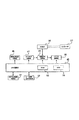
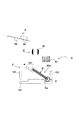
図1は、本発明の実施の形態に係るシート処理装置3を備えた画像形成装置1の模式図である。   FIG. 1 is a schematic diagram of an image forming apparatus 1 including a sheet processing apparatus 3 according to an embodiment of the present invention.

画像形成装置1は、図1に示すように、画像形成装置本体2と、シート処理装置3とから構成されている。そして、画像形成装置本体2は、原稿から画像を読み取るイメージリーダ6と、イメージリーダ6にて読み取った画像をシートに画像形成するプリンタ7とを備えている。なお、シート処理装置3は、画像形成装置本体2に例えばオプションとして着脱可能に装着する構成であっても、また画像形成装置本体2のフレーム(不図示)に一体的に組み込むような構成であってもよい。また、本実施の形態のシート処理装置3は、画像形成装置本体2にて画像形成されたシートを排出して積載する排出シート積載部5をその外部に有している。   As shown in FIG. 1, the image forming apparatus 1 includes an image forming apparatus main body 2 and a sheet processing apparatus 3. The image forming apparatus main body 2 includes an image reader 6 that reads an image from a document, and a printer 7 that forms an image read by the image reader 6 on a sheet. Note that the sheet processing apparatus 3 may be configured to be detachably attached to the image forming apparatus body 2 as an option, for example, or may be integrated into a frame (not shown) of the image forming apparatus body 2. May be. Further, the sheet processing apparatus 3 according to the present embodiment has a discharge sheet stacking unit 5 on the outside for discharging and stacking sheets formed by the image forming apparatus main body 2.

イメージリーダ6の上部には、原稿トレイ9a上にセットされた原稿を1枚ずつ給送する原稿給送装置9が搭載されている。また、イメージリーダ6は、プラテンガラス10と、プラテンガラス10の下方に設けられたスキャナユニット11と、スキャナユニット11に設けられた原稿の読取面を照射するランプ12とを備えている。更に、ランプ12による原稿からの反射光を反射・透過させるミラー13,15,16、レンズ17や、これを読み取るイメージセンサ19等を備えている。   On the upper part of the image reader 6, a document feeder 9 for feeding documents set on the document tray 9a one by one is mounted. Further, the image reader 6 includes a platen glass 10, a scanner unit 11 provided below the platen glass 10, and a lamp 12 that irradiates a document reading surface provided in the scanner unit 11. Furthermore, mirrors 13, 15, 16 for reflecting / transmitting light reflected from the original by the lamp 12, a lens 17, an image sensor 19 for reading the lens 17, and the like are provided.

プリンタ7は、記録紙等のシートを給送するシート給送装置50と、シート給送装置50から給送されるシートPに画像を形成する画像形成部20とを備えている。   The printer 7 includes a sheet feeding device 50 that feeds a sheet such as recording paper, and an image forming unit 20 that forms an image on the sheet P fed from the sheet feeding device 50.

シート給送装置50は、給紙カセットである上カセット22及び下カセット23と、ピックアップローラ25,26と、分離ローラ対27,29とを備えている。そして、上カセット22及び下カセット23内のシートPは、所定のタイミングで昇降/回転するピックアップローラ25,26と、分離ローラ対27,29との作用によって1枚ずつ分離給送されるようになっている。シート給送装置50から給送されたシートPは搬送路へと送られ、この搬送路にはレジストローラ30が配設されている。   The sheet feeding device 50 includes an upper cassette 22 and a lower cassette 23 that are sheet feeding cassettes, pickup rollers 25 and 26, and separation roller pairs 27 and 29. The sheets P in the upper cassette 22 and the lower cassette 23 are separated and fed one by one by the action of the pickup rollers 25 and 26 that move up and down at a predetermined timing and the separation roller pairs 27 and 29. It has become. The sheet P fed from the sheet feeding device 50 is sent to a conveyance path, and a registration roller 30 is disposed in the conveyance path.

画像形成部20は、電子写真方式のものであり、画像形成するためのレーザ光を出力する露光制御部31と、像担持体である感光ドラム32とを備え、露光制御部31には、レーザ光を走査するポリゴンミラー31aが設けられている。更に、画像形成部20には、感光ドラム32に現像剤を供給する現像器35や、感光ドラム32の現像剤をシート上に転写する転写部33等が備えられている。転写部33からの搬送路下流には定着部36が配設され、定着部36よりさらに下流側にはシートの進行方向を切り替えるフラッパ40と、画像形成したシートを画像形成装置本体2の外部に排出させる排出ローラ37とが配設されている。   The image forming unit 20 is of an electrophotographic system, and includes an exposure control unit 31 that outputs laser light for forming an image and a photosensitive drum 32 that is an image carrier. The exposure control unit 31 includes a laser. A polygon mirror 31a for scanning light is provided. Further, the image forming unit 20 includes a developing unit 35 that supplies a developer to the photosensitive drum 32, a transfer unit 33 that transfers the developer on the photosensitive drum 32 onto a sheet, and the like. A fixing unit 36 is disposed on the downstream side of the conveyance path from the transfer unit 33, a flapper 40 that switches the sheet traveling direction further downstream of the fixing unit 36, and an image-formed sheet outside the image forming apparatus main body 2. A discharge roller 37 for discharging is disposed.

次に、上述したような構成を有する画像形成装置本体2の各部における動作について説明する。   Next, the operation of each part of the image forming apparatus main body 2 having the above-described configuration will be described.

イメージリーダ6に搭載された原稿給送装置9は、原稿トレイ9a上に上向きにセットされた原稿を、先頭頁から順に1枚ずつ正面視左方向へと給送する。給送された原稿は湾曲したパスを介してプラテンガラス10上を左から流し読み取り位置を経て右へと搬送され、その後、外部の排紙トレイ39に向けて排出される。この原稿がプラテンガラス10上の流し読み取り位置を左から右へ向けて通過する際、流し読み取り位置に配設されたスキャナユニット11によって原稿画像が読み取られる。この読み取り方法は、一般に原稿流し読みと呼ばれるものである。そして、原稿が流し読み取り位置を通過する際、原稿の読取面がスキャナユニット11におけるランプ12の光で照射されると、その原稿からの反射光がミラー13、15、16を介してレンズ17へと導かれる。このレンズ17を通過した光は、イメージセンサ19の撮像面にて結像する。   The document feeder 9 mounted on the image reader 6 feeds the documents set upward on the document tray 9a one by one from the first page to the left in front view. The fed original is flowed from the left on the platen glass 10 through a curved path, conveyed to the right through the reading position, and then discharged toward the external paper discharge tray 39. When the original passes through the sink reading position on the platen glass 10 from the left to the right, the original image is read by the scanner unit 11 disposed at the sink reading position. This reading method is generally called document scanning. Then, when the original passes through the flow reading position, if the reading surface of the original is irradiated with the light of the lamp 12 in the scanner unit 11, the reflected light from the original passes through the mirrors 13, 15, 16 to the lens 17. It is guided. The light that has passed through the lens 17 forms an image on the imaging surface of the image sensor 19.

また、上述した原稿流し読みにおいては、原稿の搬送方向に対して直交する方向を主走査方向とし、搬送方向を副走査方向とする原稿読み取りの走査が行われる。すなわち、原稿が流し読み取り位置を通過する際に、主走査方向に原稿画像を1ライン毎にイメージセンサ19で読み取りながら、原稿を副走査方向に搬送することによって原稿画像全体の読み取りを順次行う。上記したように光学的に読み取られた原稿画像は、イメージセンサ19によって画像データに変換されて出力される。イメージセンサ19から出力された画像データは、プリンタ7の露光制御部31にビデオ信号として入力される。   In the above-described document flow scanning, document reading scanning is performed in which the main scanning direction is a direction orthogonal to the document conveyance direction and the conveyance direction is the sub-scanning direction. That is, when the original passes through the flow reading position, the entire original image is sequentially read by conveying the original in the sub-scanning direction while reading the original image by the image sensor 19 line by line in the main scanning direction. The document image optically read as described above is converted into image data by the image sensor 19 and output. Image data output from the image sensor 19 is input as a video signal to the exposure control unit 31 of the printer 7.

なお、原稿給送装置9を使用せずに原稿の読み取りを行う際には、図1の正面視奥側に設けられた不図示のヒンジを軸にして原稿給送装置9を傾けるように持ち上げて開き、プラテンガラス10上に原稿を載置して再び原稿給送装置9を元の状態に戻して閉じる。この状態から、スキャナユニット11を左から右へと走査することにより、原稿の読み取りを行うことができる。この読み取り方法は、一般に原稿固定読みという。   When reading a document without using the document feeding device 9, the document feeding device 9 is lifted so as to be tilted about a hinge (not shown) provided on the rear side in FIG. Then, the document is placed on the platen glass 10, and the document feeder 9 is returned to the original state and closed again. From this state, the document can be read by scanning the scanner unit 11 from left to right. This reading method is generally called fixed original reading.

一方、プリンタ7における露光制御部31は、イメージリーダ6から入力されたビデオ信号に基づきレーザ光を変調して出力する。このレーザ光は、ポリゴンミラー31aによって走査されながら感光ドラム32の表面に照射される。予め帯電状態にされている感光ドラム32には、走査されたレーザ光に応じた静電潜像が形成される。ここで、露光制御部31は、原稿固定読み時には、正対画像(鏡像でない画像)が形成されるようにレーザ光を出力する。この感光ドラム32上に形成された静電潜像は、現像器35から供給される現像剤によって現像剤像として可視像化される。   On the other hand, the exposure control unit 31 in the printer 7 modulates and outputs the laser beam based on the video signal input from the image reader 6. The laser light is irradiated onto the surface of the photosensitive drum 32 while being scanned by the polygon mirror 31a. An electrostatic latent image corresponding to the scanned laser beam is formed on the photosensitive drum 32 that has been charged in advance. Here, the exposure control unit 31 outputs a laser beam so that a directly-facing image (an image that is not a mirror image) is formed during document fixed reading. The electrostatic latent image formed on the photosensitive drum 32 is visualized as a developer image by the developer supplied from the developing device 35.

また、プリンタ7内の上カセット22又は下カセット23からピックアップローラ25,26によって給紙されたシートは、分離ローラ対27,29によってレジストローラ30まで搬送される。搬送されたシートの先端がレジストローラ30まで達すると、レジストローラ30は任意のタイミングで駆動され、該シートを露光制御部31のレーザ光の照射開始と同期したタイミングで感光ドラム32と転写部33との間に搬送する。ここで、感光ドラム32に形成された現像剤像は、転写部33により、搬送されたシートP上へと転写される。この現像剤像が転写されたシートは、定着部36に搬送され、定着部36は、シートを加熱及び加圧することによって現像剤像をシート上に定着させる。そして、定着部36を通過したシートは、フラッパ40及び排出ローラ37を経てプリンタ7から画像形成装置本体2の外部へと排出される。   Further, the sheet fed from the upper cassette 22 or the lower cassette 23 in the printer 7 by the pickup rollers 25 and 26 is conveyed to the registration roller 30 by the separation roller pair 27 and 29. When the leading edge of the conveyed sheet reaches the registration roller 30, the registration roller 30 is driven at an arbitrary timing, and the photosensitive drum 32 and the transfer unit 33 are driven at a timing synchronized with the start of laser irradiation of the exposure control unit 31. Carry between. Here, the developer image formed on the photosensitive drum 32 is transferred onto the conveyed sheet P by the transfer unit 33. The sheet on which the developer image is transferred is conveyed to the fixing unit 36, and the fixing unit 36 fixes the developer image on the sheet by heating and pressing the sheet. The sheet that has passed through the fixing unit 36 is discharged from the printer 7 to the outside of the image forming apparatus main body 2 through the flapper 40 and the discharge roller 37.

ここで、画像形成装置本体2にて画像形成されたシートを、その画像形成面が下向きとなった状態(いわゆるフェイスダウン)でプリンタ7から排出するには、反転パス41を用いた処理を行う。これは、定着部36を通過したシートを、フラッパ40の切替動作によって一旦反転パス41内に導き、そのシートの後端がフラッパ40を通過した後に、シートをスイッチバックさせて排出ローラ37によりプリンタ7から排出するものである。この排紙形態は、一般に反転排紙と呼ばれる。この反転排紙は、原稿給送装置9から原稿を読み取って画像形成するときや、コンピュータからの出力画像を画像形成するとき等のように、複数の原稿を先頭頁から順に画像形成するときに行われるもので、シートの頁順が揃えられて排紙される。   Here, in order to eject the sheet on which the image is formed by the image forming apparatus main body 2 from the printer 7 in a state where the image forming surface faces downward (so-called face down), processing using the reverse path 41 is performed. . This is because the sheet that has passed through the fixing unit 36 is once guided into the reversing path 41 by the switching operation of the flapper 40, and after the rear end of the sheet has passed through the flapper 40, the sheet is switched back and the discharge roller 37 performs the printer. 7 is discharged. This paper discharge form is generally called reverse paper discharge. This reverse discharge is used when images are formed in order from the first page, such as when a document is read from the document feeder 9 to form an image, or when an image output from a computer is formed. This is done, and the sheets are discharged in the same page order.

また、シート表裏の両面に画像形成を行う両面記録を行う場合には、フラッパ40の切替動作によりシートを反転パス41に導く。その後、両面搬送パス42へと搬送し、両面搬送パス42へ導かれたシートを感光ドラム32と転写部33との間に再度給紙するように制御する。   When performing double-sided recording in which image formation is performed on both the front and back sides of the sheet, the sheet is guided to the reverse path 41 by the switching operation of the flapper 40. Thereafter, the sheet is conveyed to the duplex conveyance path 42 and the sheet guided to the duplex conveyance path 42 is controlled to be fed again between the photosensitive drum 32 and the transfer unit 33.

また、OHPシートなどの硬いシートに画像形成を行う場合には、画像形成装置本体2における正面視右側に設けられた手差給紙部43から給紙を行う。この手差給紙部43から給紙されたシートに画像形成する際には、シートを反転パス41に導くことなく、画像形成面を上向きにした状態(いわゆるフェイスアップ)で排出ローラ37から排出することとなる。   Further, when an image is formed on a hard sheet such as an OHP sheet, the sheet is fed from the manual sheet feeding unit 43 provided on the right side of the image forming apparatus main body 2 as viewed from the front. When an image is formed on a sheet fed from the manual sheet feeding unit 43, the sheet is discharged from the discharge roller 37 with the image forming surface facing upward (so-called face up) without guiding the sheet to the reverse path 41. Will be.

次に、本実施の形態における画像形成装置本体2の制御系を図2に沿って説明する。図2は、画像形成装置本体2の制御系を示すブロック図である。   Next, a control system of the image forming apparatus main body 2 in the present embodiment will be described with reference to FIG. FIG. 2 is a block diagram showing a control system of the image forming apparatus main body 2.

すなわち、本制御系は、図2に示すように、CPU回路部45を有している。更に、本制御系は、このCPU回路部45に電気的に接続された、原稿給送装置制御部46、イメージリーダ制御部47、画像信号制御部49、プリンタ制御部50、操作表示装置制御部51、及びシート処理装置制御部52とを有している。   That is, this control system has a CPU circuit unit 45 as shown in FIG. Further, this control system includes a document feeding device control unit 46, an image reader control unit 47, an image signal control unit 49, a printer control unit 50, and an operation display device control unit which are electrically connected to the CPU circuit unit 45. 51 and a sheet processing apparatus control unit 52.

CPU回路部45は、CPU(図示せず)、ROM53、及びRAM55を内蔵している。ROM53は、原稿給送装置制御部46、イメージリーダ制御部47、画像信号制御部49、外部I/F56、プリンタ制御部50、操作表示装置制御部51、及びシート処理装置制御部52を総括的に制御する制御プログラムを格納する記憶装置である。RAM55は、制御プログラムや制御プログラムで参照される制御データ等の一時的な保持領域や、画像形成装置1の制御に伴う演算処理の作業領域として用いられる記憶装置である。   The CPU circuit unit 45 includes a CPU (not shown), a ROM 53, and a RAM 55. The ROM 53 includes a document feeding device control unit 46, an image reader control unit 47, an image signal control unit 49, an external I / F 56, a printer control unit 50, an operation display device control unit 51, and a sheet processing device control unit 52. This is a storage device for storing a control program to be controlled. The RAM 55 is a storage device used as a temporary storage area for control programs and control data referred to in the control program, and a work area for arithmetic processing accompanying control of the image forming apparatus 1.

原稿給送装置制御部46は、CPU回路部45からの指令に基づき、原稿給送装置9(図1参照)を駆動制御する。イメージリーダ制御部47は、CPU回路部45からの指令に基づき、図1に示したスキャナユニット11やイメージセンサ19等に対する駆動制御を行い、イメージセンサ19から出力されたアナログ画像信号を画像信号制御部49に転送する。   The document feeder control unit 46 drives and controls the document feeder 9 (see FIG. 1) based on a command from the CPU circuit unit 45. The image reader control unit 47 performs drive control on the scanner unit 11 and the image sensor 19 shown in FIG. 1 based on a command from the CPU circuit unit 45, and performs image signal control on the analog image signal output from the image sensor 19. Forward to unit 49.

画像信号制御部49は、イメージセンサ19からのアナログ画像信号をデジタル画像信号に変換した後に各種の画像処理(補正処理等)を施し、このデジタル画像信号をビデオ信号に変換してプリンタ制御部50に出力する。また、画像信号制御部49は、例えば外部のコンピュータ57から外部I/F56を介して入力されるアナログ画像信号をデジタル画像信号に変換した後に各種の画像処理を施し、このデジタル画像信号をビデオ信号に変換してプリンタ制御部50に出力する。プリンタ制御部50は、画像信号制御部49から入力されたビデオ信号に基づき、露光制御部31(図1参照)を駆動する。なお、画像信号制御部49におけるこれらの処理動作は、CPU回路部45の指令に基づいて制御される。   The image signal control unit 49 converts the analog image signal from the image sensor 19 into a digital image signal, performs various image processing (correction processing, etc.), converts the digital image signal into a video signal, and converts the digital image signal into a printer control unit 50. Output to. Further, the image signal control unit 49 performs various image processing after converting an analog image signal input from the external computer 57 via the external I / F 56 into a digital image signal, and converts the digital image signal into a video signal. And output to the printer control unit 50. The printer control unit 50 drives the exposure control unit 31 (see FIG. 1) based on the video signal input from the image signal control unit 49. Note that these processing operations in the image signal control unit 49 are controlled based on a command from the CPU circuit unit 45.

操作表示装置制御部51は、操作表示装置59(図1参照)とCPU回路部45との間における各種情報データの入出力を制御する。操作表示装置59は、画像形成に関する各種機能を設定する複数のキーや、設定状態を示す情報を表示するための表示部等を有する。そして、操作表示装置59は、各キーの操作に対応するキー信号をCPU回路部45に出力するとともに、これらCPU回路部45からの信号に応じた情報を表示部に表示する。   The operation display device control unit 51 controls input / output of various information data between the operation display device 59 (see FIG. 1) and the CPU circuit unit 45. The operation display device 59 includes a plurality of keys for setting various functions relating to image formation, a display unit for displaying information indicating a setting state, and the like. The operation display device 59 outputs a key signal corresponding to the operation of each key to the CPU circuit unit 45, and displays information corresponding to the signal from the CPU circuit unit 45 on the display unit.

シート処理装置制御部52は、制御基板として、例えばシート処理装置3に搭載され、CPU回路部45と情報データを入出力することによってシート処理装置3全体の駆動制御を行う。本シート処理装置制御部52の制御における詳細は後述する。   The sheet processing apparatus control unit 52 is mounted on the sheet processing apparatus 3 as a control board, for example, and performs drive control of the entire sheet processing apparatus 3 by inputting and outputting information data to and from the CPU circuit unit 45. Details of the control of the sheet processing apparatus control unit 52 will be described later.

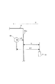
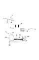
次いで、シート処理装置3の構成について図3に沿って説明する。図3は、シート処理装置3の内部構成の概略を示した模式図である。   Next, the configuration of the sheet processing apparatus 3 will be described with reference to FIG. FIG. 3 is a schematic diagram showing an outline of the internal configuration of the sheet processing apparatus 3.

シート処理装置3は、図3に示すように、画像形成装置本体2から排出されて受け入れたシートPを排出シート積載部5へと搬送する搬送パスaを有している。また、シート処理装置3は、画像形成装置本体2から受け入れたシートPに製本処理の一部を施し、後述する積載トレイ60へと搬送する搬送パスbを有している。   As shown in FIG. 3, the sheet processing apparatus 3 has a conveyance path a for conveying the sheet P discharged and received from the image forming apparatus main body 2 to the discharged sheet stacking unit 5. Further, the sheet processing apparatus 3 has a conveyance path b that performs a part of the bookbinding process on the sheet P received from the image forming apparatus main body 2 and conveys it to a stacking tray 60 described later.

搬送パスa,bの搬送方向上流端には、画像形成装置本体2から排出されるシートPをシート処理装置3内部へと搬送する搬送ローラ対61が配設されている。そして、搬送パスa,bの分岐点には、搬送ローラ対61により搬送されてくるシートPを搬送パスa又は搬送パスbへと進行方向を切り替える切替フラッパ62が配設されている。この切替フラッパ62は、不図示のソレノイドによって切り替え駆動され、切り替え駆動されない場合には、搬送ローラ対61によって搬送されるシートPはすべて搬送パスaに導入される。これに対し、切替フラッパ62が、図3に示すように切り替え駆動されている際には、搬送ローラ対61によって搬送されるシートPは搬送パスbへと導入される。   At the upstream end in the conveyance direction of the conveyance paths a and b, a conveyance roller pair 61 that conveys the sheet P discharged from the image forming apparatus main body 2 to the inside of the sheet processing apparatus 3 is disposed. A switching flapper 62 that switches the traveling direction of the sheet P conveyed by the conveyance roller pair 61 to the conveyance path a or the conveyance path b is disposed at the branch point of the conveyance paths a and b. The switching flapper 62 is switched by a solenoid (not shown). When the switching flapper 62 is not switched, all the sheets P conveyed by the conveying roller pair 61 are introduced into the conveying path a. On the other hand, when the switching flapper 62 is switched and driven as shown in FIG. 3, the sheet P conveyed by the conveying roller pair 61 is introduced into the conveying path b.

搬送パスaには、搬送ローラ対63,65,66,67が順に配設されており、これら各搬送ローラ対63,65,66,67は、搬送パスaに導入されたシートPを排出シート積載部5へと搬送する。また、搬送パスbには、搬送ローラ対69、パンチ後端センサ71、搬送ローラ対70、排紙センサ77、及び排紙ローラ76が搬送パスbに沿った状態で配設されている。そして、搬送パスbにおけるパンチ後端センサ71と搬送ローラ対70との間にはシートパンチ部Aが配設されている。このシートパンチ部Aにて穿孔処理されたシートPは、後述するシート積載部B及び製本部Cによって引き続き製本処理が行われる。そして、製本処理されたシートPは、製本束として綴じられた後に、製本排出部Dを経過して製本束積載部Eに積載される。   In the conveyance path a, conveyance roller pairs 63, 65, 66, and 67 are sequentially arranged. Each of the conveyance roller pairs 63, 65, 66, and 67 discharges the sheet P introduced into the conveyance path a. Transport to the stacking unit 5. Further, in the transport path b, a transport roller pair 69, a punch trailing edge sensor 71, a transport roller pair 70, a paper discharge sensor 77, and a paper discharge roller 76 are arranged along the transport path b. A sheet punch portion A is disposed between the punch trailing edge sensor 71 and the conveyance roller pair 70 in the conveyance path b. The sheet P punched by the sheet punching section A is subsequently subjected to bookbinding processing by a sheet stacking section B and a bookbinding section C described later. The bound sheets P are bound as a bookbinding bundle, and then stacked on the bookbinding bundle stacking section E after passing through the bookbinding discharge section D.

シートパンチ部Aは、シートに穿孔加工するパンチユニット72と、パンチユニット72を受ける受け部73と、穿孔加工後のパンチ屑を収納するパンチ屑箱75とを有している。   The sheet punch portion A includes a punch unit 72 that punches a sheet, a receiving portion 73 that receives the punch unit 72, and a punch waste box 75 that stores punch scraps after punching.

シート積載部Bは、排紙ローラ76における排紙方向下流側に配設された積載トレイ60と、積載トレイ60上に設けられた幅整合部材80と、積載トレイ60上に積載されるシートの一端(下降傾斜した下方側)を支持する板状の突当部材79とを有している。製本部Cは、シート積載部Bから送られるシート束81を把持するグリッパ(振り分け手段、保持手段)82と、シート束81に綴じ具を装着する綴じ具搬送部83とを有し、これらによってシート束81に綴じ具を装着する製本処理を行う。   The sheet stacking unit B includes a stacking tray 60 disposed on the downstream side in the sheet discharge direction of the sheet discharge roller 76, a width alignment member 80 provided on the stacking tray 60, and sheets stacked on the stacking tray 60. It has a plate-like abutting member 79 that supports one end (downwardly inclined downward side). The bookbinding section C has a gripper (sorting means, holding means) 82 for gripping the sheet bundle 81 sent from the sheet stacking section B, and a binding tool conveying section 83 for mounting the binding tool on the sheet bundle 81. A bookbinding process for attaching a binding tool to the sheet bundle 81 is performed.

図3に示す製本部Cの正面視左方には、製本部Cにて製本処理された製本束81aを、製本束積載部Eへと導く製本排出部Dが配置されている。製本排出部Dは、製本束積載部Eの上方に位置している。製本束積載部Eは、製本排出部Dから排出された製本束81aを受け、後述する製本束積載トレイ(積載手段)103上に積載する。   A bookbinding discharge section D that guides the bookbinding bundle 81a that has been bound in the bookbinding section C to the bookbinding stack stacking section E is disposed on the left side of the bookbinding section C shown in FIG. The bookbinding discharge portion D is located above the booklet bundle stacking portion E. The bookbinding bundle stacking section E receives the bookbinding bundle 81a discharged from the bookbinding discharge section D and stacks it on a bookbinding bundle stacking tray (stacking means) 103 described later.

次いで、シート処理装置3を制御するシート処理装置制御部52について図4を参照して説明する。   Next, the sheet processing apparatus control unit 52 that controls the sheet processing apparatus 3 will be described with reference to FIG.

シート処理装置制御部52は、図4に示すように、CPU89、ROM90、RAM91を有するように構成され、CPU89は、ROM90及びRAM91の資源を適宜に使って各種制御を統括動作する。ROM90は、後述する各制御部を総括的に制御する制御プログラムを格納する記憶装置である。RAM91は、制御プログラムや制御プログラムで参照される制御データ等の一時的な保持領域や、シート処理装置3の制御に伴う演算処理の作業領域として用いられる記憶装置である。   As shown in FIG. 4, the sheet processing apparatus control unit 52 is configured to include a CPU 89, a ROM 90, and a RAM 91, and the CPU 89 performs overall control of various controls using resources of the ROM 90 and the RAM 91 as appropriate. The ROM 90 is a storage device that stores a control program that comprehensively controls each control unit described below. The RAM 91 is a storage device used as a temporary storage area for control programs and control data referred to in the control program, and a work area for arithmetic processing accompanying control of the sheet processing apparatus 3.

また、CPU89は、搬送制御部92、パンチ制御部93、積載制御部95、綴じ具制御部96、及び排紙制御部97の各制御部を実行制御する。搬送制御部92は、前述した各搬送ローラ対61,69,70や排紙ローラ76等によるシート搬送の駆動制御を行い、パンチ制御部93は、シートパンチ部Aの駆動制御を行う。積載制御部95はシート積載部Bの駆動制御を行い、綴じ具制御部96は製本部Cの駆動制御を行う。また、排紙制御部97は、製本束積載部Eに製本束を排出する製本排出部D、及び製本束積載トレイ103上に製本束を積載する製本束積載部Eの駆動制御を行う。   In addition, the CPU 89 executes and controls the control units of the transport control unit 92, the punch control unit 93, the stacking control unit 95, the binding tool control unit 96, and the paper discharge control unit 97. The conveyance control unit 92 performs drive control of sheet conveyance by each of the conveyance roller pairs 61, 69, 70, the paper discharge roller 76, and the like, and the punch control unit 93 performs drive control of the sheet punch unit A. The stacking control unit 95 controls the driving of the sheet stacking unit B, and the binding control unit 96 controls the driving of the bookbinding unit C. Further, the paper discharge control unit 97 performs drive control of the bookbinding discharge unit D that discharges the booklet bundle to the booklet bundle stacking unit E and the booklet bundle stacking unit E that loads the booklet bundle on the booklet bundle stacking tray 103.

そして、シート処理装置制御部52は、画像形成装置本体2に設けられたCPU回路部45と不図示の通信ICを介してデータ交換等を行うことにより製本処理を実行制御する。シート処理装置制御部52では、画像形成装置本体2におけるCPU回路部45からの指示に基づき、ROM90に格納されている各種プログラムが実行され、シート処理装置3が駆動制御される。   The sheet processing apparatus control unit 52 executes and controls bookbinding processing by exchanging data and the like via a CPU circuit unit 45 provided in the image forming apparatus main body 2 and a communication IC (not shown). In the sheet processing apparatus control unit 52, various programs stored in the ROM 90 are executed based on instructions from the CPU circuit unit 45 in the image forming apparatus main body 2, and the sheet processing apparatus 3 is driven and controlled.

なお、上述したCPU89は、シート処理装置3におけるシート処理装置制御部52に搭載されているとして説明したが、画像形成装置本体2等が備える制御基板に搭載されているものであってもよい。更には、別体のパソコン等の情報機器におけるCPUであってもよく、シート処理装置3の制御処理を行うCPUは必ずしもシート処理装置3自身が備えている必要はないものとする。このように、CPUが、別体の情報機器に備えられている場合には通信回線等(有線、無線を問わず)を介して信号が送受信され、各種の制御処理がなされるものとする。また、このような態様は、上記したCPUだけでなく他のRAMやROM等についても同様である。   Although the above-described CPU 89 is described as being mounted on the sheet processing apparatus control unit 52 in the sheet processing apparatus 3, the CPU 89 may be mounted on a control board provided in the image forming apparatus main body 2 or the like. Further, it may be a CPU in an information device such as a separate personal computer, and the CPU that performs control processing of the sheet processing apparatus 3 does not necessarily have to be provided in the sheet processing apparatus 3 itself. As described above, when the CPU is provided in a separate information device, signals are transmitted and received via a communication line or the like (whether wired or wireless), and various control processes are performed. In addition, this aspect is the same not only for the CPU described above but also for other RAMs and ROMs.

次に、シート処理装置3の動作について図5を参照して説明する。図5は、パンチ後端センサ71と停止したシートPとの位置関係を示す図である。   Next, the operation of the sheet processing apparatus 3 will be described with reference to FIG. FIG. 5 is a diagram showing a positional relationship between the punch trailing edge sensor 71 and the stopped sheet P.

図3に示したように、シート処理装置3は、画像形成装置本体2における排出ローラ37によって排出されるシートPを、搬送ローラ対61によりシート処理装置3内へと搬送する。シート処理装置3は、搬送したシートPを排出シート積載部5へと搬送する場合には、図示しないソレノイドによって切替フラッパ62を切り替え駆動し、シートPを搬送パスaに導くようにする。この搬送パスaへと導かれたシートPは、更に搬送ローラ対63,65,66,67によって搬送され、排出シート積載部5へと排出される。   As shown in FIG. 3, the sheet processing apparatus 3 conveys the sheet P discharged by the discharge roller 37 in the image forming apparatus main body 2 into the sheet processing apparatus 3 by the conveyance roller pair 61. When conveying the conveyed sheet P to the discharged sheet stacking unit 5, the sheet processing apparatus 3 switches and drives the switching flapper 62 by a solenoid (not shown) so as to guide the sheet P to the conveyance path a. The sheet P guided to the conveyance path a is further conveyed by the conveyance roller pairs 63, 65, 66, and 67 and is discharged to the discharge sheet stacking unit 5.

一方、シート処理装置3では、画像形成装置本体2から搬送したシートPに製本処理を行う場合には、シートPが搬送パスbへ導かれるように切替フラッパ62が図3に示す状態へと切り替えられる。そして、シートPが搬送パスbへと導かれると、シートパンチ部Aによって以下のような穿孔処理が行われる。   On the other hand, in the sheet processing apparatus 3, when the bookbinding process is performed on the sheet P conveyed from the image forming apparatus main body 2, the switching flapper 62 is switched to the state shown in FIG. 3 so that the sheet P is guided to the conveyance path b. It is done. When the sheet P is guided to the conveyance path b, the following punching process is performed by the sheet punch unit A.

搬送ローラ対69に挟持されたシートPは、搬送方向下流側へと搬送され、搬送ローラ対70によって更に下流側へと搬送される。その際、パンチ後端センサ71によってシートPの後端が検知されると、搬送ローラ対70は、シートPをその検知位置から図5の矢印Sで示すシート搬送方向に所定距離Lだけ搬送して停止する。この所定距離Lは、図5に示すように、パンチ後端センサ71における検知位置からパンチユニット72の中心位置までの固定距離L1と、シートPの後端(綴じられた側)Peからパンチ穴Hの中心位置までの可変距離L2との差となっている。つまり、シートPをパンチ後端センサ71の検知位置から所定距離Lだけ搬送して停止させることにより、パンチユニットの中心位置を後端PeからシートP上の所望の位置に移動させることができる。   The sheet P sandwiched between the conveyance roller pair 69 is conveyed downstream in the conveyance direction, and is further conveyed downstream by the conveyance roller pair 70. At this time, when the trailing edge of the sheet P is detected by the punch trailing edge sensor 71, the conveying roller pair 70 conveys the sheet P from the detection position by a predetermined distance L in the sheet conveying direction indicated by the arrow S in FIG. And stop. As shown in FIG. 5, the predetermined distance L is a fixed distance L1 from the detection position of the punch rear end sensor 71 to the center position of the punch unit 72, and the punch hole from the rear end (bound side) Pe of the sheet P. This is a difference from the variable distance L2 to the center position of H. In other words, the center position of the punch unit can be moved from the rear end Pe to a desired position on the sheet P by transporting the sheet P by a predetermined distance L from the detection position of the punch rear end sensor 71 and stopping it.

そして、パンチユニット72は、パンチ後端センサ71から所定距離Lだけ搬送された位置に停止したシートPに向って、不図示のパンチモータによって下降駆動される。これにより、パンチユニット72は、受け部73との間にシートPを挟み込み、シートPに対して穿孔加工する。この穿孔加工の後、該加工により生じたパンチ屑はパンチ屑箱75へと収納され、パンチユニット72は受け部73から再び上昇駆動される。   The punch unit 72 is driven downward by a punch motor (not shown) toward the sheet P stopped at a position conveyed by a predetermined distance L from the punch trailing edge sensor 71. Accordingly, the punch unit 72 sandwiches the sheet P between the receiving unit 73 and punches the sheet P. After this drilling process, punch scrap generated by the processing is stored in the punch scrap box 75, and the punch unit 72 is driven to rise again from the receiving portion 73.

シート処理装置3は、シートPに対する穿孔処理が終了し、パンチユニット72を上昇駆動すると、停止していたシートPの搬送を搬送ローラ対70によって再開させる。その後、排紙ローラ76の搬送方向上流側に配置されている排紙センサ77によってシートPの後端Peが検知されると、排紙ローラ76は、所定の速度Vに切り替えてシートPを積載トレイ60へと排紙する。なお、本実施の形態では、速度Vを例えば300mm/sとする。また、積載トレイ60に対してシートPが排紙される際、その速度が速度Vに比してかなり遅い場合には、シートPの後端Peが排紙ローラ76にもたれ掛かるような状態が生じ得る。また、逆に、その速度が速度Vに比してかなり速い場合には、シートPが積載トレイ60内に収まって静止しないような状態が生じ得る。従って、排紙ローラ76によりシートPを排紙する速度は、常に上述したような所定の速度Vとする。   When the punching process for the sheet P is completed and the punch unit 72 is driven upward, the sheet processing apparatus 3 resumes the stopped conveyance of the sheet P by the conveyance roller pair 70. After that, when the trailing edge Pe of the sheet P is detected by the sheet discharge sensor 77 disposed on the upstream side in the transport direction of the sheet discharge roller 76, the sheet discharge roller 76 switches to a predetermined speed V and stacks the sheet P. The paper is discharged to the tray 60. In the present embodiment, the speed V is set to 300 mm / s, for example. In addition, when the sheet P is discharged to the stacking tray 60 and its speed is considerably slower than the speed V, the rear end Pe of the sheet P leans against the discharge roller 76. Can occur. On the contrary, when the speed is considerably higher than the speed V, a state may occur in which the sheets P are stored in the stacking tray 60 and are not stationary. Accordingly, the speed at which the sheet P is discharged by the paper discharge roller 76 is always the predetermined speed V as described above.

次いで、上述したシートパンチ部Aから搬送されたシートPは、シート積載部Bにて以下のような処理がなされる。   Next, the sheet P conveyed from the sheet punching section A described above is processed in the sheet stacking section B as follows.

排紙ローラ76から積載トレイ60上へ排紙されたシートPは、前述した所定の速度Vで排紙されることにより、排紙ローラ76に対してもたれ掛かるようなことがなく、積載トレイ60上に着地する。積載トレイ60は全体として、図3に示すように、排紙ローラ76近傍側の高さが低くなるように設けられている。これにより、排紙ローラ76から排紙されて積載トレイ60上に着地したシートPは、自重で排紙方向上流側(図3の正面視右下方向)へと移動して突当部材79に当接するので、シートPが複数積載されたシート束81の端部が整列される。   The sheet P discharged from the discharge roller 76 onto the stacking tray 60 is discharged at the predetermined speed V described above, so that the sheet P does not lean against the discharge roller 76 and is not stacked. Land on top. As shown in FIG. 3, the stacking tray 60 is provided so that the height in the vicinity of the paper discharge roller 76 is lowered as a whole. As a result, the sheet P discharged from the discharge roller 76 and landing on the stacking tray 60 moves to the upstream side in the discharge direction (downward right in the front view in FIG. 3) by its own weight and moves to the abutting member 79. Since they abut, the end portions of the sheet bundle 81 on which a plurality of sheets P are stacked are aligned.

また、積載トレイ60には、底面60aから突出した板状の幅整合部材80が、排紙ローラ76から排紙されるシートPを左右両側(図3の正面視手前側と奥側と)から挟み込むように幅方向に移動自在に配設されている。この幅整合部材80は、搬送ローラ対70により搬送中のシートPの先端が排紙ローラ76に到達した時点では、積載トレイ60のシートPが積載される位置の左右両側で、シートPの左右それぞれ外側10mmの位置に移動して待機している。   Further, on the stacking tray 60, a plate-like width aligning member 80 protruding from the bottom surface 60a allows the sheet P to be discharged from the discharge roller 76 from the left and right sides (front side and front side in FIG. 3). It is arranged to be movable in the width direction so as to be sandwiched. When the leading edge of the sheet P being conveyed by the conveyance roller pair 70 reaches the paper discharge roller 76, the width alignment member 80 is located on the left and right sides of the position where the sheets P of the stacking tray 60 are stacked. Each of them moves to a position of 10 mm outside and stands by.

そして、幅整合部材80は、排紙ローラ76により排紙されたシートPが積載トレイ60上に着地すると、上記待機していた位置からシートPを挟み込むように10mm内側に移動する。このように、シートPが積載トレイ60上に一枚排紙されるごとに上述したような整合動作を繰り返すことから、シート束81の左右端部及び前後端部の位置は確実に整合されることとなる。   Then, when the sheet P discharged by the discharge roller 76 lands on the stacking tray 60, the width alignment member 80 moves inward 10 mm so as to sandwich the sheet P from the standby position. As described above, since the alignment operation as described above is repeated every time one sheet P is discharged onto the stacking tray 60, the positions of the left and right end portions and the front and rear end portions of the sheet bundle 81 are reliably aligned. It will be.

なお、シートPが積載トレイ60上に着地した否かの判断は、シートPの後端が排紙ローラ76を抜けた時点からの経過時間を不図示のタイマで計測することにより判定する。また、シートPの後端が排紙ローラ76を抜ける際のタイミングは、排紙センサ77がシートPの後端を検知してからの排紙ローラ76の搬送速度と搬送距離とによって容易に判定し得るものである。   Whether or not the sheet P has landed on the stacking tray 60 is determined by measuring the elapsed time from the time when the trailing edge of the sheet P has passed through the paper discharge roller 76 with a timer (not shown). The timing at which the trailing edge of the sheet P passes through the sheet discharge roller 76 is easily determined based on the conveyance speed and conveyance distance of the sheet discharge roller 76 after the sheet discharge sensor 77 detects the trailing edge of the sheet P. It is possible.

次に、上述したシート積載部Bから搬送されたシートPは、製本部Cにて以下のような処理がなされる。この製本部Cの動作については、図6〜12を参照して説明する。   Next, the sheet P conveyed from the sheet stacking unit B described above is subjected to the following processing in the bookbinding unit C. The operation of the bookbinding unit C will be described with reference to FIGS.

積載トレイ60に積載され、整列されたシートPのシート束81は、図6に示すように、積載トレイ60上にてグリッパ82により把持され、シート積載部Bから製本部Cの上方へ、矢印T1の向きに束の状態で移動される。製本部Cの上方へと移動されたシート束81は、図7に示すように、グリッパ82に把持されたまま、綴じ具(綴じ手段)R(図8参照)によって綴じられる側の端部、つまりシート束81の後端Pe側の端部を下に向けるように矢印T2の向きに回転される。   As shown in FIG. 6, the sheet bundle 81 of the sheets P stacked and aligned on the stacking tray 60 is gripped by the gripper 82 on the stacking tray 60, and the arrow moves upward from the sheet stacking unit B to the bookbinding unit C. The bundle is moved in the direction of T1. As shown in FIG. 7, the sheet bundle 81 moved to the upper side of the bookbinding portion C is held by the gripper 82 and is bound by the binding tool (binding means) R (see FIG. 8). That is, the sheet bundle 81 is rotated in the direction of the arrow T2 so that the end on the rear end Pe side of the sheet bundle 81 faces downward.

このようにシート束81が移動されると、シート束81の後端Peが綴じ具搬送部83に臨む状態、つまり綴じ具搬送部83の奥側に重なった状態(図7参照)となり、この状態から綴じ具搬送部83によって綴じ具Rが装着されることとなる。綴じ具Rの具体的な装着動作については、後述する図9〜12にて説明する。なお、上記した綴じ具Rは金属製の螺旋状バインダである。また、この螺旋状バインダは、金属製以外のプラスチック等でもよく、製本処理に要する硬度や柔軟性等を有していればその材質は特に限定されるものではない。   When the sheet bundle 81 is moved in this manner, the rear end Pe of the sheet bundle 81 faces the binding tool transport unit 83, that is, a state where the sheet bundle 81 overlaps the back side of the binding tool transport unit 83 (see FIG. 7). From the state, the binding tool R is mounted by the binding tool transport unit 83. Specific mounting operation of the binding tool R will be described with reference to FIGS. The binding tool R described above is a metal spiral binder. The helical binder may be plastic other than metal, and the material is not particularly limited as long as it has the hardness and flexibility required for bookbinding.

シート束81が、製本部Cにおける図7に示す位置に移動されると、次に綴じ具Rの装着が行われる。この製本部Cにおける綴じ具Rの装着動作について、図9〜12を参照して以下で詳細に説明する。   When the sheet bundle 81 is moved to the position shown in FIG. 7 in the bookbinding unit C, the binding tool R is next attached. The attaching operation of the binding tool R in the bookbinding portion C will be described in detail below with reference to FIGS.

ここで、製本部Cにおける綴じ具搬送部83は、図9に示すように、綴じ具Rを移動する綴じ具搬送ローラ85、これを駆動する不図示のモータ、及び綴じ具Rを保持する綴じ具挿入軸86からなる。綴じ具挿入軸86は、綴じ具Rの正面視の内径にほぼ等しい外径を有し、その表面に綴じ具Rと同じピッチの螺旋状の溝が形成されている。この綴じ具挿入軸86は固定されており、綴じ具搬送ローラ85が回転して綴じ具Rが搬送された際にあっても回転及び移動することはない。   Here, as illustrated in FIG. 9, the binding tool transporting unit 83 in the bookbinding unit C includes a binding tool transporting roller 85 that moves the binding tool R, a motor (not illustrated) that drives the binding tool R, and a binding that holds the binding tool R. It consists of a tool insertion shaft 86. The binding tool insertion shaft 86 has an outer diameter substantially equal to the inner diameter in front view of the binding tool R, and a helical groove having the same pitch as the binding tool R is formed on the surface thereof. The binding tool insertion shaft 86 is fixed and does not rotate or move even when the binding tool transport roller 85 rotates and the binding tool R is transported.

綴じ具Rを搬送するには、図9に示すように、綴じ具挿入軸86にセットされた綴じ具Rに対し、その螺旋形状の外側から綴じ具搬送ローラ85の円筒外面を接触させる。この状態から、不図示のモータによって綴じ具搬送ローラ85を矢印X1に示す方向に回転させると、綴じ具挿入軸86の溝にセットされている綴じ具Rに動力が伝えられる。これにより、図10に示すように、綴じ具Rは綴じ具挿入軸86の溝に沿って矢印Y2方向に搬送が開始され、綴じ具搬送部83は、シート束81へ向けて綴じ具Rを先端から順次送り出すこととなる。   In order to transport the binding tool R, as shown in FIG. 9, the cylindrical outer surface of the binding tool transport roller 85 is brought into contact with the binding tool R set on the binding tool insertion shaft 86 from the outside of the spiral shape. From this state, when the binding tool transport roller 85 is rotated in the direction indicated by the arrow X1 by a motor (not shown), power is transmitted to the binding tool R set in the groove of the binding tool insertion shaft 86. As a result, as shown in FIG. 10, the binding tool R starts to be transported in the direction of the arrow Y2 along the groove of the binding tool insertion shaft 86, and the binding tool transport unit 83 moves the binding tool R toward the sheet bundle 81. It will be sent out sequentially from the tip.

シート束81がグリッパ82によって製本部C上方の製本位置へ移動されると、図10に示すように、綴じ具搬送部83による綴じ具Rの搬送が開始される。綴じ具搬送部83は、図11に示すように、グリッパ82に把持されているシート束81のパンチ穴Hに対し、綴じ具Rを回転させつつその先端から順に通過させていく。そして、図12に示すように、綴じ具搬送部83は、綴じ具Rをシート束81における全てのパンチ穴Hに通した時点で綴じ具Rの搬送を終了する。   When the sheet bundle 81 is moved to the bookbinding position above the bookbinding unit C by the gripper 82, the binding tool R starts to be conveyed by the binding tool conveyance unit 83 as shown in FIG. As shown in FIG. 11, the binding tool conveyance unit 83 sequentially passes the binding tool R through the punch holes H of the sheet bundle 81 held by the gripper 82 while rotating the binding tool R. Then, as illustrated in FIG. 12, the binding tool transport unit 83 ends the transport of the binding tool R when the binding tool R passes through all punch holes H in the sheet bundle 81.

綴じ具搬送部83によってシート束81に綴じ具Rが装着されると、この製本束81aは、図8に示すように、グリッパ82に把持されたまま矢印T3方向へと平行移動され、製本束積載部E上方の製本排出部Dへと移動される。   When the binding tool R is attached to the sheet bundle 81 by the binding tool conveyance unit 83, the bookbinding bundle 81a is translated in the direction of the arrow T3 while being held by the gripper 82, as shown in FIG. It is moved to the bookbinding discharge section D above the stacking section E.

次いで、本発明の特徴となる製本束積載部Eについて、図13〜24に沿って詳細に説明する。   Next, the bookbinding bundle stacking portion E, which is a feature of the present invention, will be described in detail with reference to FIGS.

製本束積載部Eは、束ガイド(振り分け手段、振り分け部材)101、シート束規制板(整合手段)102、及び製本束積載トレイ103から構成されている。   The bookbinding bundle stacking section E includes a bundle guide (sorting means, sorting member) 101, a sheet bundle regulating plate (alignment means) 102, and a bookbinding bundle stacking tray 103.

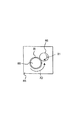
束ガイド101は、図13に示すように、モータ105に嵌合され、モータ105からの回転が軸101aに伝達されることで矢印R1,R2方向に正逆転可能に配設されている。更に、モータ105の近傍には、不図示のモータと、該モータに嵌合されたピニオン部とが配設されている。そして、該ピニオン部には、図13の正面視左右幅方向に延びるラック部が噛合されており、これらピニオン部とラック部とによってラックアンドピニオン(rack and pinion)機構が構成されている。   As shown in FIG. 13, the bundle guide 101 is fitted to the motor 105, and is disposed so as to be able to rotate forward and backward in the directions of arrows R <b> 1 and R <b> 2 by transmitting the rotation from the motor 105 to the shaft 101 a. Further, in the vicinity of the motor 105, a motor (not shown) and a pinion portion fitted to the motor are disposed. A rack portion extending in the left-right width direction in front view of FIG. 13 is engaged with the pinion portion, and a rack and pinion mechanism is configured by the pinion portion and the rack portion.

そして、モータ105は、上記したラック部に固定されるとともに、該ラック部に沿うように形成されたガイド部材106に摺動可能に支持されている。従って、モータ105は、上記不図示のモータからの回転が伝達された際、ラックアンドピニオンを介して移動の動力が与えられ、ガイド部材106に沿って図13の正面視左右幅方向に移動駆動されるものとなる。なお、上記したモータ105及びガイド部材106は、後述する図14〜図21及び図25ではその図示を省略する。   The motor 105 is fixed to the rack portion described above and is slidably supported by a guide member 106 formed along the rack portion. Accordingly, when the rotation from the motor (not shown) is transmitted, the motor 105 is given power for movement through the rack and pinion, and is driven to move along the guide member 106 in the left-right width direction as viewed from the front in FIG. Will be. The motor 105 and the guide member 106 described above are not shown in FIGS. 14 to 21 and FIG. 25 described later.

製本排出部Dに移動されてきた製本束81aは、上述した束ガイド101が矢印R1,R2の2方向に回動することにより、製本束積載トレイ103に落下する際の落下方向が振り分けられる。ここで、製本束81aにおける綴じ具Rが装着された後端Peからパンチ穴Hを含む範囲を綴じ部(綴じ手段で綴じられた部分)Ra(図15参照)とし、この綴じ部Raが、例えば図13に示す製本束積載トレイ103の正面視右側を向くように積載されるとする。この場合、束ガイド101は、その片側端部が右下を向く状態まで回動(矢印R1方向)され、製本排出部Dから落下される製本束81aを誘導する。また、綴じ部Raが、製本束積載トレイ103の図13に示す正面視左側を向くように積載させる場合には、束ガイド101が、その片側端部を左下に向く状態まで回動(矢印R2方向)させて製本束81aの落下する向きを誘導する。   The bookbinding bundle 81a that has been moved to the bookbinding discharge section D is distributed in the direction of dropping when it is dropped onto the bookbinding bundle stacking tray 103 by rotating the bundle guide 101 in the two directions indicated by arrows R1 and R2. Here, a range including the punch hole H from the rear end Pe on which the binding tool R is mounted in the bookbinding bundle 81a is a binding portion (portion bound by the binding means) Ra (see FIG. 15), and the binding portion Ra is For example, it is assumed that the booklet bundle stacking tray 103 shown in FIG. In this case, the bundle guide 101 is rotated (in the direction of the arrow R1) until one end portion thereof is directed to the lower right, and guides the bookbinding bundle 81a dropped from the bookbinding discharge section D. Further, when the binding portion Ra is stacked so as to face the left side in front view shown in FIG. 13 of the bookbinding bundle stacking tray 103, the bundle guide 101 is rotated to a state where one end portion thereof is directed to the lower left (arrow R2). Direction) to guide the direction in which the bookbinding bundle 81a falls.

一方、束ガイド101は、製本排出部Dの直下方がホームポジション(初期位置)となっている。束ガイド101は、製本束排出部Dから排出される製本束81aの落下方向を誘導する際には、このホームポジションに位置している。しかし、製本束81aを誘導した後は、該製本束81aを製本束積載トレイ103上に寝かせるように積み重ねるため、前述した不図示のラックアンドピニオン機構によってホームポジションから左右方向に移動される。   On the other hand, the bundle guide 101 has a home position (initial position) immediately below the bookbinding discharge portion D. The bundle guide 101 is located at this home position when guiding the dropping direction of the bookbinding bundle 81a discharged from the bookbinding bundle discharge portion D. However, after the bookbinding bundle 81a is guided, the bookbinding bundle 81a is stacked on the bookbinding bundle stacking tray 103 so as to be laid down, so that the bookbinding bundle 81a is moved left and right from the home position by the rack and pinion mechanism (not shown).

シート束規制板102は、製本束積載トレイ103に積載する製本束81aの整合性を高めるため、積載された製本束81aが図13の正面視左右方向に広がらないように、製本束81aの左右端部を規制する。シート束規制板102は、不図示のモータにより図13の正面視左右方向(矢印S1,S2方向)にそれぞれ移動可能となっており、積載する製本束のサイズや綴じ具の径等の値によって決定された位置(待機位置)へと移動される。   The sheet bundle restricting plate 102 increases the consistency of the bookbinding bundle 81a loaded on the bookbinding bundle stacking tray 103, so that the stacked bookbinding bundle 81a does not spread in the left-right direction when viewed from the front in FIG. Regulate the edge. The sheet bundle restricting plate 102 can be moved in the left-right direction (in the direction of arrows S1 and S2) in FIG. 13 by a motor (not shown), depending on values such as the size of the bookbinding bundle to be stacked and the diameter of the binding tool. It is moved to the determined position (standby position).

製本束積載トレイ103は、不図示のモータにより図13の正面視上下方向(矢印U1,U2方向)に移動可能となっている。更に、製本束積載トレイ103は、積載した製本束81aの最上面が常に一定の位置となるように、不図示の紙面検知センサの検知に基づいた上記モータの動作によって移動制御される。   The bookbinding bundle stacking tray 103 is movable in a vertical direction (in the directions of arrows U1 and U2) in front view of FIG. 13 by a motor (not shown). Further, the bookbinding bundle stacking tray 103 is moved and controlled by the operation of the motor based on the detection of a paper surface detection sensor (not shown) so that the uppermost surface of the stacked bookbinding bundle 81a is always at a fixed position.

次いで、製本部Cにおける製本束の作成処理(製本処理)から、この製本処理後の製本束積載部Eにおける製本束排出の処理までの動作について詳細に説明する。なお、この製本部Cにおける製本処理から製本束積載部Eにおける製本束排出の処理までの一連の処理単位(一組の製本束を生成・排出する単位工程)を、以下で製本ジョブと呼ぶ。   Next, operations from the bookbinding bundle creation process (bookbinding process) in the bookbinding unit C to the booklet bundle discharge process in the bookbinding bundle stacking unit E after the bookbinding process will be described in detail. A series of processing units from the bookbinding process in the bookbinding unit C to the booklet bundle discharge process in the booklet bundle stacking unit E (unit process for generating and discharging a set of bookbinding bundles) is hereinafter referred to as a bookbinding job.

図13には、上記製本ジョブの開始前における製本束積載部Eの状態が示されている。図13に示すように、束ガイド101は製本束排出部Dの直下方のホームポジションに配置されており、また、製本束積載トレイ103には製本束が積載されていないため、製本束積載トレイ103は最も上昇した状態となっている。シート束規制板102は、画像形成装置本体2から搬送される製本束のサイズに応じて算出された待機位置に向けて(矢印S1,S2参照)、最初の製本束81aが製本排出部Dに搬送される以前に移動し終える。   FIG. 13 shows a state of the bookbinding bundle stacking section E before the bookbinding job is started. As shown in FIG. 13, the bundle guide 101 is disposed at a home position directly below the bookbinding bundle discharge portion D, and no booklet bundle is loaded on the bookbinding bundle stacking tray 103. 103 is in the most elevated state. The sheet bundle regulating plate 102 is moved toward the standby position calculated according to the size of the bookbinding bundle conveyed from the image forming apparatus main body 2 (see arrows S1 and S2), and the first bookbinding bundle 81a is sent to the bookbinding discharge section D. Finish moving before being transported.

上記した製本束のサイズは、画像形成するシートに応じ、画像形成装置本体2の操作表示装置59に表示された選択値からユーザによって選択設定される。この操作表示装置59に表示される選択値は、シート処理装置制御部52のROM90に一般的なシートの規格値のテーブルデータとして予め記憶されており、これらの値が画像形成する際に操作表示装置59に表示される。前述した待機位置は、この選択されたシートサイズに基づき、排紙制御部97にて算出される。なお、このシートサイズはユーザにより選択設定されるものとして説明したが、シートサイズの値を計測し得る装置をシート処理装置3内に配設して検出させるようにしてもよく、その取得方法については特に限定されるものではない。   The size of the bookbinding bundle is selected and set by the user from the selection value displayed on the operation display device 59 of the image forming apparatus main body 2 according to the sheet on which the image is to be formed. The selection values displayed on the operation display device 59 are stored in advance in the ROM 90 of the sheet processing apparatus control unit 52 as table data of general sheet standard values, and these values are displayed when the image is formed. Displayed on the device 59. The above-described standby position is calculated by the paper discharge control unit 97 based on the selected sheet size. Although the sheet size has been described as being selected and set by the user, an apparatus capable of measuring the sheet size value may be disposed in the sheet processing apparatus 3 to be detected. Is not particularly limited.

ここで、シート束規制板102における待機位置の算出の仕方について、図22〜24を参照して説明する。   Here, how to calculate the standby position in the sheet bundle regulating plate 102 will be described with reference to FIGS.

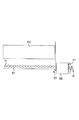
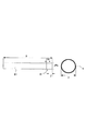
正面視左右側に配置されるシート束規制板102の待機位置は、図24に示すように、重なり合った状態の製本束81aにおける幅の距離Wであるとする。図22は、製本前のシート束81及び綴じ具Rに係る各サイズを示すものであり、シート束81の搬送方向の左右幅を距離X、綴じ具Rの直径を距離Y、及びシート束81の後端Peからパンチ穴Hの近接エッジまでを距離Zとする。また、上記パンチ穴Hの直径は距離Hdとする。   As shown in FIG. 24, the standby position of the sheet bundle regulating plate 102 arranged on the left and right sides in the front view is assumed to be a distance W in the width of the bookbinding bundle 81a in an overlapped state. FIG. 22 shows the sizes of the sheet bundle 81 and the binding tool R before bookbinding. The left and right widths in the conveying direction of the sheet bundle 81 are the distance X, the diameter of the binding tool R is the distance Y, and the sheet bundle 81. A distance Z is defined from the rear end Pe to the adjacent edge of the punch hole H. The diameter of the punch hole H is a distance Hd.

また、製本後の製本束81aに係るサイズは、図23に示すように、綴じ具Rの後端部(正面視右端)からその後端部と反対側のパンチ穴Hの縁部(正面視左端)までの距離を距離Mとする。また、製本後の綴じ具Rの後端部からその後端部と反対側の製本束81aの端部(書籍でいう小口)までの距離を距離Nとする。以上の前提から、上記距離Mと距離Nとは下記の式にて表される。   Further, as shown in FIG. 23, the size of the bookbinding bundle 81a after bookbinding is the edge of the punch hole H on the opposite side from the rear end (right end in front view) of the binding tool R (left end in front view). ) Is a distance M. Further, the distance N from the rear end of the binding tool R after bookbinding to the end of the bookbinding bundle 81a on the side opposite to the rear end (small edge referred to as a book) is defined as a distance N. Based on the above assumptions, the distance M and the distance N are expressed by the following equations.

X+Y−Z−Hd ≦ N ≦ X+Y−Z …(1)
Y ≦ M ≦ Y+Hd …(2)
W = M+N …(3)
X + Y−Z−Hd ≦ N ≦ X + Y−Z (1)
Y ≦ M ≦ Y + Hd (2)
W = M + N (3)

上記式(1)において、距離Nが最小となるのは、綴じ具Rがパンチ穴H内部で最も製本束81aの内側(図23の左右幅方向の中央側)へ移動している場合となる。また、これに対して距離Nが最大となるのは、綴じ具Rがパンチ穴H内部で最も製本束81aの外側(図23の左右幅方向の右端側)に寄った場合となる。なお、実際にはシート束81の厚みと綴じ具Rの内径とによって、綴じ具Rの移動可能範囲は制限されるが本実施の形態では無視するものとする。   In the above formula (1), the distance N is minimum when the binding tool R is moved most inside the bookbinding bundle 81a (the center in the left-right width direction in FIG. 23) inside the punch hole H. . On the other hand, the distance N is maximum when the binding tool R is closest to the outside of the bookbinding bundle 81a (the right end side in the left-right width direction in FIG. 23) inside the punch hole H. In practice, the movable range of the binding tool R is limited by the thickness of the sheet bundle 81 and the inner diameter of the binding tool R, but is ignored in the present embodiment.

そして、製本束81aを製本束積載トレイ103上に複数積載する際に、最も積載効率を良くする(つまり積載空間を節約する)ためには、複数の製本束81aの各綴じ部Raが左右交互に向くような状態に積載すると良い。これにより、製本束81aの積載効率の向上を図ることができるようになる。更に、先に積載された製本束81aの綴じ部Raと後に積載された製本束81aの小口側の端部とが接触せず、先に積載された製本束81aの小口側端部と後に積載された製本束81aの綴じ部Raとが接触しない状態であることが望ましい。これは、上記式(3)において、距離Wが最大値を取るような場合である。   When a plurality of bookbinding bundles 81a are stacked on the bookbinding bundle stacking tray 103, the binding portions Ra of the plurality of bookbinding bundles 81a are alternately arranged on the left and right sides in order to improve the stacking efficiency (that is, to save the stacking space). It is good to load it in the state that is suitable for. As a result, the stacking efficiency of the bookbinding bundle 81a can be improved. Further, the binding portion Ra of the bookbinding bundle 81a loaded first and the edge portion on the edge side of the bookbinding bundle 81a loaded later do not come into contact with each other, and the edge portion on the edge edge side of the bookbinding bundle 81a loaded earlier and the latter are loaded later. It is desirable that the binding portion Ra of the bound bookbinding bundle 81a is not in contact. This is a case where the distance W takes the maximum value in the above equation (3).

ここで、式(3)において距離Wが最大値を取るのは、式(1)において距離Nが最大値を取り、式(2)において距離Mが最大値を取る場合である。このとき距離Wは、
W = X+2Y−Z+Hd …(4)
となる。この結果から、シート束規制板102の待機位置として、左右側に配置されたシート束規制板102同士の間隔が、上記した距離Wの位置となるように移動させればよいものとなる。従って、本実施の形態における製本束積載部Eには、シート束規制板102が上記距離Wの位置に変更可能となるように不図示のモータが設けられている。
Here, the distance W takes the maximum value in the equation (3) when the distance N takes the maximum value in the equation (1) and the distance M takes the maximum value in the equation (2). At this time, the distance W is
W = X + 2Y−Z + Hd (4)
It becomes. From this result, as the standby position of the sheet bundle restricting plate 102, the distance between the sheet bundle restricting plates 102 arranged on the left and right sides may be moved to the position of the distance W described above. Therefore, a motor (not shown) is provided in the bookbinding bundle stacking section E in the present embodiment so that the sheet bundle regulating plate 102 can be changed to the position of the distance W.

ところで、グリッパ82に把持されて、製本排出部Dへと搬送された製本束81aは、図15に示すように、グリッパ82の把持(保持)が解除されることによって製本束積載部Eへと落下する。   By the way, the bookbinding bundle 81a gripped by the gripper 82 and conveyed to the bookbinding discharge section D is moved to the bookbinding stack stacking section E by releasing the gripping (holding) of the gripper 82 as shown in FIG. Fall.

このとき、落下した製本束81aは、その下方に位置する束ガイド101に当接し、束ガイド101が正面視右下側に傾斜していることによって、製本束81aにおける綴じ部Raが、図15の正面視右側へと誘導されることとなる。製本束積載トレイ103の正面視右側へと誘導された上記製本束81aは、図16に示すように、その綴じ部Raがシート束規制板102に接触しつつ下方に案内されるように製本束積載トレイ103に落下する。   At this time, the dropped bookbinding bundle 81a abuts against the bundle guide 101 positioned below the booklet bundle 81a, and the bundle guide 101 is inclined to the lower right side when viewed from the front. Will be guided to the right side of the front view. As shown in FIG. 16, the bookbinding bundle 81a guided to the right side of the bookbinding bundle stacking tray 103 is guided downward while the binding portion Ra is in contact with the sheet bundle regulating plate 102. Drops onto the loading tray 103.

製本束積載トレイ103の図17の正面視右端部に綴じ部Raが落下して当接すると、束ガイド101は、製本束81aの後端部分がもたれ掛かった状態から図17の矢印W1に示す方向に移動する。これにより、束ガイド101は、製本束81aの綴じ部Raをシート束規制板102近傍に位置させたまま、製本束81aを製本束積載トレイ103上に積載させる(図18参照)。そして、製本束81aが積載されると、製本束積載トレイ103は、不図示の紙面検知センサにより、製本束81aの最上面が所定の高さ位置となるように図19に示す矢印G方向に下降駆動される。   When the binding portion Ra drops and comes into contact with the right end of the bookbinding bundle stacking tray 103 as viewed from the front in FIG. 17, the bundle guide 101 is shown by an arrow W1 in FIG. 17 from the state in which the rear end portion of the bookbinding bundle 81a leans. Move in the direction. Thus, the bundle guide 101 stacks the bookbinding bundle 81a on the bookbinding bundle stacking tray 103 while the binding portion Ra of the bookbinding bundle 81a is positioned in the vicinity of the sheet bundle regulating plate 102 (see FIG. 18). When the bookbinding bundle 81a is stacked, the bookbinding bundle stacking tray 103 is moved in the direction of arrow G shown in FIG. 19 so that the uppermost surface of the bookbinding bundle 81a is at a predetermined height position by a paper surface detection sensor (not shown). Driven down.

上記した1個目の製本束81aの積載が完了した後、束ガイド101は、図19に示すように、矢印W2方向に移動して前述したホームポジション(製本排出部Dの真下の位置)へ戻る。そして、図20に示すように、製本排出部Dから次に落下してくる製本束81bの綴じ部Raを、製本束積載トレイ103の左側へと変えるため、束ガイド101は、束ガイド101の正面視左側が下を向く状態となるように軸101aを中心に回転する。   After the stacking of the first bookbinding bundle 81a is completed, the bundle guide 101 moves in the direction of the arrow W2 as shown in FIG. 19 to the above-described home position (position just below the bookbinding discharge section D). Return. Then, as shown in FIG. 20, in order to change the binding portion Ra of the bookbinding bundle 81 b falling next from the bookbinding discharge section D to the left side of the bookbinding bundle stacking tray 103, the bundle guide 101 is It rotates around the shaft 101a so that the left side when viewed from the front faces downward.

2個目の製本束81bが製本され、グリッパ82により製本排出部Dに搬送されると、1個目のときと同様に、グリッパ82の把持が解除され、製本束81bが製本束積載部Eへと落下する。図20に示すように、製本束81bは、綴じ部Raが矢印R2方向に回転した束ガイド101に当たることよって製本束積載トレイ103の正面視左側へと誘導される。そして、製本束81bは、左側のシート束規制板102に当接しつつ製本束積載トレイ103上に落下する。   When the second bookbinding bundle 81b is bound and conveyed to the bookbinding discharge section D by the gripper 82, the gripping of the gripper 82 is released and the bookbinding bundle 81b is bound to the bookbinding bundle stacking section E as in the first case. Fall into As shown in FIG. 20, the bookbinding bundle 81b is guided to the left side of the bookbinding bundle stacking tray 103 when the binding portion Ra hits the bundle guide 101 rotated in the arrow R2 direction. Then, the bookbinding bundle 81 b falls onto the bookbinding bundle stacking tray 103 while being in contact with the left sheet bundle regulating plate 102.

このとき、束ガイド101は、図21に示すように、1個目のときとは逆に当該製本束81bの後端部分がもたれ掛かった状態から正面視右側(矢印W2方向)へと移動する。これにより、製本束81bは、製本束積載トレイ103上の製本束81aの上に、綴じ具Rによって綴じられた部分が製本束81aと左右反対となった状態で積載されることとなる。つまり、綴じ具で綴じられた製本束81bの端部が、先に製本束積載トレイ103上積載された最上位の製本束81aにおける綴じ具で綴じられた端部の対向辺側となるように、製本束81bが積載される。また、製本束81aと製本束81bとは、それぞれ綴じ部Raを除いたシート部分の上下面同士が接して積み重なる状態となり、製本束81aの積載効率の向上を図ることができるようになる。そして、製本束81bの積載完了後には、製本束積載トレイ103は、1個目の製本束81aのときと同様、製本束81bの最上面を所定の高さ位置とするように矢印G方向に下降する。   At this time, as shown in FIG. 21, the bundle guide 101 moves from the state in which the rear end portion of the bookbinding bundle 81b leans against the right side (in the direction of arrow W2) as opposed to the first case. . As a result, the bookbinding bundle 81b is stacked on the bookbinding bundle 81a on the bookbinding bundle stacking tray 103 in a state in which the portion bound by the binding tool R is opposite to the bookbinding bundle 81a. That is, the end portion of the bookbinding bundle 81b bound by the binding tool is located on the side opposite to the end portion bound by the binding tool in the uppermost bookbinding bundle 81a loaded on the bookbinding bundle stacking tray 103 first. The bookbinding bundle 81b is loaded. Further, the bookbinding bundle 81a and the bookbinding bundle 81b are in a state where the upper and lower surfaces of the sheet portions excluding the binding portion Ra are in contact with each other and stacked, so that the stacking efficiency of the bookbinding bundle 81a can be improved. After the bookbinding bundle 81b is completely stacked, the bookbinding bundle stacking tray 103 is moved in the direction of the arrow G so that the uppermost surface of the bookbinding bundle 81b is at a predetermined height position as in the case of the first bookbinding bundle 81a. Descend.

上記2個目の製本束81bの積載完了後、束ガイド101は、前述したホームポジションへ矢印W1方向(図17参照)に戻る。そして、製本排出部Dから次に落下してくる製本束の落下方向先端を、製本束積載トレイ103の逆側へと変えるため、束ガイド101は、束ガイド101の正面視右側が下を向く状態となるように軸101aを中心に回転する。   After completing the loading of the second bookbinding bundle 81b, the bundle guide 101 returns to the home position described above in the direction of arrow W1 (see FIG. 17). Then, in order to change the leading end of the bookbinding bundle falling from the bookbinding discharge section D to the opposite side of the bookbinding bundle stacking tray 103, the bundle guide 101 has the right side of the bundle guide 101 in front view facing downward. It rotates about the shaft 101a so as to be in a state.

このように、シート処理装置3では、上述した動作を繰り返し、形成された製本束を製本束積載トレイ103上に効率よく積み重ねて積載していく。例えば、図25では、10個の束を積載した際の製本束積載部Eの状態を示している。   As described above, in the sheet processing apparatus 3, the above-described operation is repeated, and the formed bookbinding bundle is efficiently stacked and stacked on the bookbinding bundle stacking tray 103. For example, FIG. 25 shows a state of the bookbinding bundle stacking section E when 10 bundles are stacked.

なお、本実施の形態では、束ガイド101の軸101aを中心とした角度を変えることにより製本束81aの綴じ部Raの落下方向を振り分けるとして説明した。しかし、これ以外にも、例えば、グリッパ82を回動させるモータを備えさせ、製本束81aをグリッパ82で把持した状態で該グリッパ82を回転させて落下方向を変えるようにしてもよい。本発明にあっては、製本束81aの落下方向の振り分けに関する機構や構造については特に限定されるものではない。   In the present embodiment, it has been described that the falling direction of the binding portion Ra of the bookbinding bundle 81a is distributed by changing the angle around the axis 101a of the bundle guide 101. However, in addition to this, for example, a motor for rotating the gripper 82 may be provided, and the gripper 82 may be rotated while the bookbinding bundle 81 a is held by the gripper 82 to change the dropping direction. In the present invention, the mechanism and structure relating to the sorting of the bookbinding bundle 81a in the dropping direction are not particularly limited.

また、本実施の形態にて説明した画像形成装置1の構成は、一般的な画像形成装置の一例を示すものであり、他の付属する装置を備えた構成となっていてよいことは勿論である。   Further, the configuration of the image forming apparatus 1 described in the present embodiment is an example of a general image forming apparatus, and it is needless to say that the image forming apparatus 1 may include other attached devices. is there.

また、綴じ具Rは、金属製の螺旋状バインダとして説明したが、円環形状や櫛形状等のものであってもよく、その形状は特に限定されるものではない。   Moreover, although the binding tool R was demonstrated as a metal helical binder, it may be in a ring shape or a comb shape, and the shape is not particularly limited.

以上説明したように、本実施の形態によれば、製本束積載トレイ103の上方に位置するグリッパ82と束ガイド101とにより、製本束81aを、その落下方向を振り分けながら製本束積載トレイ103に落下させる。そして、この落下方向が振り分けられながら落下した製本束81aをシート束規制板102に当接させる。これにより、この製本束81aにおける綴じ部Raを除いた領域が順次積み重なるように構成されるので、製本束積載トレイ103における製本束の積載効率の向上を図ることができるようになる。   As described above, according to the present embodiment, the bookbinding bundle 81a is distributed to the bookbinding bundle stacking tray 103 while sorting the dropping direction by the gripper 82 and the bundle guide 101 positioned above the bookbinding bundle stacking tray 103. Drop it. Then, the bookbinding bundle 81a dropped while the dropping direction is distributed is brought into contact with the sheet bundle regulating plate 102. As a result, since the region excluding the binding portion Ra in the bookbinding bundle 81a is configured to be stacked sequentially, the stacking efficiency of the bookbinding bundle on the bookbinding bundle stacking tray 103 can be improved.

また、グリッパ82は、製本束81aの後端Pe側を下方に向けて該製本束81aを落下させるので、製本束81aの落下時の姿勢が安定するとともに後端Pe側から着地することとなる。これにより、製本束81aの小口側が折れたり傷がついたりすることを防ぐことができるようになる。   Further, since the gripper 82 drops the bookbinding bundle 81a with the rear end Pe side of the bookbinding bundle 81a facing downward, the posture when the bookbinding bundle 81a is dropped is stabilized and landed from the rear end Pe side. . Thereby, it becomes possible to prevent the side edge of the bookbinding bundle 81a from being broken or damaged.

また、グリッパ82と束ガイド101とによって製本束81aの落下方向を振り分けることができるので、製本束積載トレイ103上に簡易な構成で効率よく製本束81aを積載できるようになる。   Further, since the gripper 82 and the bundle guide 101 can distribute the direction in which the bookbinding bundle 81a falls, the bookbinding bundle 81a can be efficiently stacked on the bookbinding bundle stacking tray 103 with a simple configuration.

以上のように、本発明にかかるシート処理装置及び画像形成装置は、綴じ具を用いて製本処理するシート処理装置に有用であり、特に、製本束の積載効率の向上を図ることを要するシート処理装置及び画像形成装置に適している。   As described above, the sheet processing apparatus and the image forming apparatus according to the present invention are useful for a sheet processing apparatus that performs a bookbinding process using a binding tool, and in particular, a sheet process that needs to improve the stacking efficiency of a bookbinding bundle. Suitable for the apparatus and the image forming apparatus.

本発明の実施の形態に係るシート処理装置を備えた画像形成装置の模式図である。1 is a schematic diagram of an image forming apparatus including a sheet processing apparatus according to an embodiment of the present invention. 画像形成装置本体の制御系を示すブロック図である。2 is a block diagram illustrating a control system of the image forming apparatus main body. FIG. シート処理装置の内部構成の概略を示した模式図である。FIG. 2 is a schematic diagram illustrating an outline of an internal configuration of a sheet processing apparatus. シート処理装置の制御系を示すブロック図である。3 is a block diagram illustrating a control system of the sheet processing apparatus. FIG. パンチ後端センサと停止したシートとの位置関係を示す図である。It is a figure which shows the positional relationship of the punch rear end sensor and the stopped sheet. 製本部における製本処理の第1状態を示す説明図である。It is explanatory drawing which shows the 1st state of the bookbinding process in a bookbinding part. 製本部における製本処理の第2状態を示す説明図である。It is explanatory drawing which shows the 2nd state of the bookbinding process in a bookbinding part. 製本部における製本処理の第3状態を示す説明図である。It is explanatory drawing which shows the 3rd state of the bookbinding process in a bookbinding part. 綴じ具搬送部の概略断面図である。It is a schematic sectional drawing of a binding tool conveyance part. 綴じ具搬送部による綴じ具装着の初期状態を示す概略図である。It is the schematic which shows the initial state of the binding tool mounting | wearing by a binding tool conveyance part. 綴じ具搬送部による綴じ具装着の経過状態を示す概略図である。It is the schematic which shows the progress state of the binding tool mounting | wearing by a binding tool conveyance part. 綴じ具搬送部による綴じ具装着の終了状態を示す概略図である。It is the schematic which shows the completion | finish state of binding tool mounting | wearing by a binding tool conveyance part. 製本束積載部の概略を示した模式図である。It is the schematic diagram which showed the outline of the bookbinding bundle stacking part. 束ガイドの動作を示した模式図である。It is the schematic diagram which showed operation | movement of the bundle guide. 製本束積載部における積載処理の第1状態を示す説明図である。It is explanatory drawing which shows the 1st state of the stacking process in a bookbinding bundle stacking part. 製本束積載部における積載処理の第2状態を示す説明図である。It is explanatory drawing which shows the 2nd state of the stacking process in a bookbinding bundle stacking part. 製本束積載部における積載処理の第3状態を示す説明図である。It is explanatory drawing which shows the 3rd state of the stacking process in a bookbinding bundle stacking part. 製本束積載部における積載処理の第4状態を示す説明図である。It is explanatory drawing which shows the 4th state of the stacking process in a bookbinding bundle stacking part. 製本束積載部における積載処理の第5状態を示す説明図である。It is explanatory drawing which shows the 5th state of the stacking process in a bookbinding bundle stacking part. 製本束積載部における積載処理の第6状態を示す説明図である。It is explanatory drawing which shows the 6th state of the stacking process in a bookbinding bundle stacking part. 製本束積載部における積載処理の第7状態を示す説明図である。It is explanatory drawing which shows the 7th state of the stacking process in a bookbinding bundle stacking part. シート束と綴じ具の個別の各部寸法を示す説明図である。It is explanatory drawing which shows each part dimension of a sheet | seat bundle and a binding tool. 製本束の各部寸法を示す説明図である。It is explanatory drawing which shows each part dimension of a bookbinding bundle. 製本束が積み重なった状態の左右幅の寸法を示す説明図である。It is explanatory drawing which shows the dimension of the left-right width | variety of the state in which the bookbinding bundle was piled up. 10個の製本束が積載された製本束積載部の例を示す模式図である。It is a schematic diagram which shows the example of the bookbinding bundle loading part in which ten bookbinding bundles were loaded.

符号の説明Explanation of symbols

1 画像形成装置
3 シート処理装置
20 画像形成部
81 シート束
81a 製本束
82 振り分け手段、保持手段(グリッパ)
101 振り分け手段、振り分け部材(束ガイド)
102 整合手段(シート束規制板)
103 積載手段(製本束積載トレイ)
H パンチ穴
P シート
Pe 綴じられた側(後端)
R 綴じ手段(綴じ具)、綴じ具
Ra 綴じ手段で綴じられた部分
DESCRIPTION OF SYMBOLS 1 Image forming apparatus 3 Sheet processing apparatus 20 Image forming part 81 Sheet bundle 81a Bookbinding bundle 82 Sorting means, holding means (gripper)
101 Sorting means, sorting member (bundle guide)
102 Alignment means (sheet bundle regulating plate)
103 Stacking means (bookbinding stack stack tray)
H Punch hole P Sheet Pe The bound side (rear end)
R Binding means (binding tool), binding tool Ra Portion bound by binding means

Claims (8)

綴じ手段で端部が綴じられた製本束を積載するシート処理装置において、
製本束が積載される積載手段と、
綴じ手段で綴じられた端部が、前記積載手段に先に積載された最上位の製本束における綴じ手段で綴じられた端部の対向辺側となるように、製本束を前記積載手段に積載させる手段と、を有することを特徴とするシート処理装置。
In a sheet processing apparatus for stacking a bookbinding bundle whose ends are bound by a binding means,
A loading means on which the bookbinding bundle is loaded;
The bookbinding bundle is stacked on the stacking means such that the end bound by the binding means is on the opposite side of the end bound by the binding means in the uppermost bookbinding bundle previously stacked on the stacking means. And a sheet processing apparatus.
綴じ手段で綴じられた製本束が積載される積載手段と
前記積載手段の上方に位置し、前記製本束を、落下方向を振り分けながら前記積載手段に落下させる振り分け手段と、
前記積載手段に向けて前記落下方向が振り分けられながら落下した製本束と当接して前記製本束を整合する整合手段と、を備え、
前記落下方向が振り分けられて落下した製本束を、前記綴じ手段で綴じられた部分を除いた領域で前記積載手段の上に順次積み重ねるように構成したことを特徴とするシート処理装置。
A stacking unit on which the bookbinding bundle bound by the binding unit is stacked; a sorting unit which is positioned above the stacking unit and drops the bookbinding bundle onto the stacking unit while sorting the dropping direction;
Alignment means for abutting the bookbinding bundle that has fallen while the drop direction is distributed toward the stacking means and aligning the bookbinding bundle;
A sheet processing apparatus configured to sequentially stack the bookbinding bundles that have been dropped after the dropping direction is sorted on the stacking unit in an area excluding a portion bound by the binding unit.
前記綴じ手段は、シート束に穿孔されたパンチ穴に装着される螺旋状の綴じ具からなることを特徴とする請求項1または2に記載のシート処理装置。   The sheet processing apparatus according to claim 1, wherein the binding unit includes a spiral binding tool attached to a punch hole formed in the sheet bundle. 前記振り分け手段は、前記製本束の綴じられた側を下方に向けて前記製本束を落下させることを特徴とする請求項2に記載のシート処理装置。   The sheet processing apparatus according to claim 2, wherein the sorting unit drops the bookbinding bundle with the bound side of the bookbinding bundle facing downward. 前記振り分け手段は、
形成された前記製本束を保持し、前記積載手段の上方で前記製本束の保持を解除して前記製本束を落下させる保持手段と、
前記積載手段と前記保持手段との間に設けられ、落下する製本束と当接するとともに前記落下する製本束と当接する角度を変えることにより、前記製本束の落下方向を振り分ける振り分け部材と、からなることを特徴とする請求項2に記載のシート処理装置。
The sorting means is
Holding means for holding the formed bookbinding bundle, releasing the holding of the bookbinding bundle above the stacking means, and dropping the bookbinding bundle;
A sorting member which is provided between the stacking means and the holding means, and abuts the falling bookbinding bundle and distributes the falling direction of the bookbinding bundle by changing an angle of contact with the falling bookbinding bundle. The sheet processing apparatus according to claim 2.
前記整合手段の位置は、形成される製本束のサイズに応じて変更可能であることを特徴とする請求項2に記載のシート処理装置。   The sheet processing apparatus according to claim 2, wherein the position of the aligning unit can be changed according to the size of the bookbinding bundle to be formed. 端部が綴じ手段で綴じられた製本束が積載される積載手段と、
前記綴じ手段で綴じられた部分を除いた領域で前記積載手段の上に製本束を順次積み重ねるための手段と、を有することを特徴とするシート処理装置。
A stacking unit on which a bookbinding bundle whose ends are bound by the binding unit is stacked;
And a means for sequentially stacking the bookbinding bundle on the stacking means in an area excluding the portion bound by the binding means.
シートに画像を形成する画像形成部と、
前記画像形成部で画像が形成されたシートを処理するシート処理装置と、を備えた画像形成装置において、
前記シート処理装置が、請求項1ないし7のいずれかに記載のシート処理装置である、ことを特徴とする画像形成装置。
An image forming unit for forming an image on a sheet;
An image forming apparatus comprising: a sheet processing apparatus that processes a sheet on which an image is formed in the image forming unit.
An image forming apparatus, wherein the sheet processing apparatus is the sheet processing apparatus according to claim 1.
JP2007147203A 2007-06-01 2007-06-01 Sheet processor and image forming device Pending JP2008297098A (en)

Priority Applications (1)

Application Number Priority Date Filing Date Title
JP2007147203A JP2008297098A (en) 2007-06-01 2007-06-01 Sheet processor and image forming device

Applications Claiming Priority (1)

Application Number Priority Date Filing Date Title
JP2007147203A JP2008297098A (en) 2007-06-01 2007-06-01 Sheet processor and image forming device

Publications (2)

Publication Number Publication Date
JP2008297098A true JP2008297098A (en) 2008-12-11
JP2008297098A5 JP2008297098A5 (en) 2010-07-15

Family

ID=40170975

Family Applications (1)

Application Number Title Priority Date Filing Date
JP2007147203A Pending JP2008297098A (en) 2007-06-01 2007-06-01 Sheet processor and image forming device

Country Status (1)

Country Link
JP (1) JP2008297098A (en)

Cited By (2)

* Cited by examiner, † Cited by third party
Publication number Priority date Publication date Assignee Title
JP2012006667A (en) * 2010-06-22 2012-01-12 Konica Minolta Business Technologies Inc Post finishing device and image forming system
JP2020026341A (en) * 2018-08-13 2020-02-20 キヤノンファインテックニスカ株式会社 Sheet bundle discharge device

Citations (4)

* Cited by examiner, † Cited by third party
Publication number Priority date Publication date Assignee Title
JPH09142723A (en) * 1995-11-16 1997-06-03 Nisca Corp Sheet processing device
JP2000059552A (en) * 1998-08-06 2000-02-25 Fuji Xerox Co Ltd Sheet bunch load equalization method and image forming device to which the same method is applied
JP2001192162A (en) * 2000-01-11 2001-07-17 Canon Inc Saddle stitching and folding bookbinding delivery apparatus and image forming apparatus
JP2003171053A (en) * 2001-12-03 2003-06-17 Canon Inc Sheet processing device and image forming device having the same

Patent Citations (4)

* Cited by examiner, † Cited by third party
Publication number Priority date Publication date Assignee Title
JPH09142723A (en) * 1995-11-16 1997-06-03 Nisca Corp Sheet processing device
JP2000059552A (en) * 1998-08-06 2000-02-25 Fuji Xerox Co Ltd Sheet bunch load equalization method and image forming device to which the same method is applied
JP2001192162A (en) * 2000-01-11 2001-07-17 Canon Inc Saddle stitching and folding bookbinding delivery apparatus and image forming apparatus
JP2003171053A (en) * 2001-12-03 2003-06-17 Canon Inc Sheet processing device and image forming device having the same

Cited By (3)

* Cited by examiner, † Cited by third party
Publication number Priority date Publication date Assignee Title
JP2012006667A (en) * 2010-06-22 2012-01-12 Konica Minolta Business Technologies Inc Post finishing device and image forming system
JP2020026341A (en) * 2018-08-13 2020-02-20 キヤノンファインテックニスカ株式会社 Sheet bundle discharge device
JP7148316B2 (en) 2018-08-13 2022-10-05 キヤノンファインテックニスカ株式会社 Sheet bundle discharge device

Similar Documents

Publication Publication Date Title
JP4895384B2 (en) Sheet processing apparatus and image forming apparatus
JP4580431B2 (en) Post-processing equipment
US8413978B2 (en) Sheet processing apparatus and image forming system
JP2006315812A (en) Sheet processing device, and image forming device
JP2008238694A (en) Bookbinding system and bookbinding apparatus
JP2007062912A (en) Image forming device, its control method, program and recording medium
JP2006056671A (en) Aftertreatment device
JP2004271633A (en) Sheet processing device
JP2010195584A (en) Sheet processing apparatus and image forming apparatus
CN100430840C (en) Sheet processing apparatus having a sheet insertion function, control method therefor, image forming apparatus
JP2012063703A (en) Image forming apparatus and control method therefor
JP4324141B2 (en) Image forming apparatus
US20120319344A1 (en) Sheet atacker and finisher
JP2006036493A (en) Sheet handling device and image forming device equipped with it
JP4638517B2 (en) Image processing device
JP4808535B2 (en) Sheet processing apparatus and image forming apparatus
JP2007050526A (en) Image forming system, image forming apparatus, method for controlling image forming system and image forming method
JP4684929B2 (en) Post-processing apparatus and image forming system
JP2008297098A (en) Sheet processor and image forming device
JP5741240B2 (en) Post-processing apparatus and image forming system
JP2009120331A (en) Sheet stacking device and image forming device
JP2013086892A (en) Image forming apparatus
JP4976752B2 (en) Sheet processing apparatus and image forming apparatus
JP6150063B2 (en) Post-processing apparatus and image forming system
JP4259451B2 (en) Image forming system and post-processing apparatus

Legal Events

Date Code Title Description
A521 Written amendment

Free format text: JAPANESE INTERMEDIATE CODE: A523

Effective date: 20100528

A621 Written request for application examination

Free format text: JAPANESE INTERMEDIATE CODE: A621

Effective date: 20100528

A977 Report on retrieval

Effective date: 20111205

Free format text: JAPANESE INTERMEDIATE CODE: A971007

A131 Notification of reasons for refusal

Effective date: 20111213

Free format text: JAPANESE INTERMEDIATE CODE: A131

RD05 Notification of revocation of power of attorney

Free format text: JAPANESE INTERMEDIATE CODE: A7425

Effective date: 20120125

RD03 Notification of appointment of power of attorney

Free format text: JAPANESE INTERMEDIATE CODE: A7423

Effective date: 20120203

A521 Written amendment

Free format text: JAPANESE INTERMEDIATE CODE: A523

Effective date: 20120213

A02 Decision of refusal

Effective date: 20120925

Free format text: JAPANESE INTERMEDIATE CODE: A02