JP2008296323A - Power tool - Google Patents
Power tool Download PDFInfo
- Publication number
- JP2008296323A JP2008296323A JP2007144689A JP2007144689A JP2008296323A JP 2008296323 A JP2008296323 A JP 2008296323A JP 2007144689 A JP2007144689 A JP 2007144689A JP 2007144689 A JP2007144689 A JP 2007144689A JP 2008296323 A JP2008296323 A JP 2008296323A
- Authority
- JP
- Japan
- Prior art keywords
- trigger
- rotation speed
- speed
- amount
- motor
- Prior art date
- Legal status (The legal status is an assumption and is not a legal conclusion. Google has not performed a legal analysis and makes no representation as to the accuracy of the status listed.)
- Pending
Links
Images


Classifications
-
- B—PERFORMING OPERATIONS; TRANSPORTING
- B25—HAND TOOLS; PORTABLE POWER-DRIVEN TOOLS; MANIPULATORS
- B25F—COMBINATION OR MULTI-PURPOSE TOOLS NOT OTHERWISE PROVIDED FOR; DETAILS OR COMPONENTS OF PORTABLE POWER-DRIVEN TOOLS NOT PARTICULARLY RELATED TO THE OPERATIONS PERFORMED AND NOT OTHERWISE PROVIDED FOR
- B25F5/00—Details or components of portable power-driven tools not particularly related to the operations performed and not otherwise provided for
Abstract
Description
本発明は、ネジ締付用ビット等の先端工具を駆動する電動工具に関し、特に、先端工具を駆動するための電動モータの回転数をトリガスイッチの押込量に応答して制御する制御回路部を有する電動工具に関する。 The present invention relates to an electric tool for driving a tip tool such as a screw tightening bit, and more particularly to a control circuit unit for controlling the number of rotations of an electric motor for driving the tip tool in response to the pushing amount of a trigger switch. It has an electric power tool.
電動モータにより駆動されるドリル、ドライバ等の回転先端工具を有する電動工具において、トリガ操作部をもつトリガスイッチの操作により、電動工具の動力源となる電動モータの回転数を制御する技術が、例えば下記特許文献1に開示されている。この技術ではトリガスイッチの押込量(操作量)、すなわち変位量に応答して電動モータに供給する印加電圧を可変させることによってモータの回転数を制御している。
In an electric tool having a rotary tip tool such as a drill or a driver driven by an electric motor, a technique for controlling the rotation speed of an electric motor serving as a power source of the electric tool by operating a trigger switch having a trigger operation unit is, for example, It is disclosed in the following
一般的には、トリガスイッチのトリガ押込量の上昇とともに、トリガ押込量に比例して印加電圧を上昇させ、結果的にトリガ押込量に比例してモータ回転数を増加させるように制御している。このような制御は、作業開始時に、モータの回転数が急速に立上るのを防止して低い回転数でモータを回転させることによって、ネジ締め、穴あけ、切削等の作業において先端工具を被加工物に対して位置決めもしくは加工をし易くするためである。 Generally, as the trigger push amount of the trigger switch increases, the applied voltage is increased in proportion to the trigger push amount, and as a result, the motor rotation speed is controlled to increase in proportion to the trigger push amount. . Such control prevents the rapid rotation of the motor at the start of the work and rotates the motor at a low speed, so that the tip tool can be machined in operations such as screw tightening, drilling, and cutting. This is to facilitate positioning or processing with respect to the object.
上述したような従来のトリガスイッチによるモータ制御方式では、トリガ操作部の押込量(操作量)とともにモータ回転数が比例的に急上昇するので、電動工具を使用する作業者には、トリガ押込量を小さくするようにトリガスイッチを把持して、モータ回転数を所望の低速領域に保持する微妙なトリガ操作が要求された。 In the motor control system using the conventional trigger switch as described above, the motor rotation speed increases proportionally with the pressing amount (operation amount) of the trigger operation unit. A delicate trigger operation is required to hold the motor rotation number in a desired low speed region by holding the trigger switch so as to be small.
しかしながら、実際には作業者がトリガ押込量を小さく保持する操作は難しく、微妙なトリガ押込量の変動により電動モータの回転動作が不安定になってしまうという問題があった。例えば、トリガ押込量が小さくしすぎてモータが停止し、または電動モータの印加電圧がモータを起動できないように制御する場合がある。逆に、トリガ押込量を大きくしすぎてモータ回転数を急激に上昇させる場合には、電動工具のドライバビット等の先端工具が被加工部材の所定位置決め箇所から外れてしまい、先端工具が被加工部材を損傷させるという問題を生じた。さらに、電動工具の操作性が損なわれ、作業効率が低下するという問題を招く場合もあった。 However, in practice, it is difficult for the operator to keep the trigger push-in amount small, and there is a problem that the rotational operation of the electric motor becomes unstable due to a slight variation in the trigger push-in amount. For example, there is a case where the trigger is pushed too small to stop the motor, or the voltage applied to the electric motor is controlled so that the motor cannot be started. Conversely, if the trigger push amount is increased too much and the motor rotation speed is increased rapidly, the end tool such as the driver bit of the electric tool is disengaged from the predetermined position of the workpiece, and the end tool is processed. This caused the problem of damaging the member. Furthermore, the operability of the electric power tool is impaired, and there may be a problem that work efficiency is lowered.
従って、本発明の一つの目的は、電動モータの回転開始時における回転数の制御を容易にするために、トリガスイッチの操作性を改善したトリガスイッチ制御回路を具備する電動工具を提供することにある。 Accordingly, an object of the present invention is to provide an electric tool including a trigger switch control circuit in which the operability of the trigger switch is improved in order to facilitate the control of the rotation speed at the start of rotation of the electric motor. is there.
本発明の他の目的は、従来の上記問題点を解決するために、トリガスイッチの押込量に基づくモータの回転数制御を改善したブラシレス直流モータを具備する電動工具を提供することにある。 Another object of the present invention is to provide an electric tool including a brushless DC motor in which the rotational speed control of the motor based on the pushing amount of the trigger switch is improved in order to solve the above-described conventional problems.
上記本発明の目的を達成するために、本願において開示される発明のうち、代表的なものの特徴を説明すれば、次のとおりである。 In order to achieve the above object of the present invention, typical features of the invention disclosed in the present application will be described as follows.
本発明の一つの特徴によれば、ハウジング部内に装着される電動モータと、該電動モータによって回転駆動される前記ハウジング部に設けられた先端工具と、ハウジング部に設けられたトリガスイッチ部と、該トリガスイッチ部のトリガ押込量によって前記電動モータの回転数を回転開始から全速回転数まで制御するための制御回路部とを有する電動工具において、前記制御回路部は、前記トリガスイッチ部の前記トリガ押込量が第1の押込量以下の第1の押込範囲では、前記電動モータの回転数を、前記先端工具の負荷へ回転力を伝達するための下限回転数と、前記全速回転数より低い先端工具の操作性によって規定される上限回転数との間の第1の回転数範囲内において、所定の第1の回転数上昇率で上昇させるか、または一定回転数となるように前記トリガ押込量に応答して制御し、かつ、前記トリガスイッチ部の前記トリガ押込量が前記第1の押込量を超えて最大の押込量に至る第2の押込範囲内では、前記電動モータの回転数を、前記上限回転数と前記全速回転数との間の第2の回転数範囲内において、前記第1の押込範囲における前記第1の回転数上昇率より高い第2の回転数上昇率で上昇させるように前記トリガ押込量に応答して制御する。 According to one aspect of the present invention, an electric motor mounted in the housing portion, a tip tool provided in the housing portion that is rotationally driven by the electric motor, a trigger switch portion provided in the housing portion, An electric tool having a control circuit unit for controlling the rotation speed of the electric motor from the rotation start to the full-speed rotation speed according to a trigger pressing amount of the trigger switch unit, wherein the control circuit unit is configured to control the trigger of the trigger switch unit. In the first indentation range in which the indentation amount is equal to or less than the first indentation amount, the rotation speed of the electric motor is set to the lower limit rotation speed for transmitting the rotational force to the load of the tip tool and the tip lower than the full speed rotation speed. Within a first rotational speed range between the upper limit rotational speed defined by the operability of the tool, it is increased at a predetermined first rotational speed increase rate, or a constant rotational speed In the second push range in which the trigger push amount of the trigger switch unit is controlled in response to the trigger push amount and reaches the maximum push amount exceeding the first push amount, Second rotation of the electric motor within a second rotation speed range between the upper limit rotation speed and the full speed rotation speed is higher than the first rotation speed increase rate in the first push-in range. Control is performed in response to the trigger push-in amount so as to increase at a numerical increase rate.
本発明の他の特徴によれば、前記電動モータの回転数を、前記第1の押込範囲では一定回転数に制御し、前記第2の押込範囲では前記一定回転数より前記全速回転数へ上昇させるように制御する。 According to another feature of the invention, the rotational speed of the electric motor is controlled to a constant rotational speed in the first pushing range, and is increased from the constant rotational speed to the full speed rotational speed in the second pushing range. To control.
本発明のさらに他の特徴によれば、前記トリガスイッチ部の前記トリガ押込量は、ポテンショメータによって電圧の高さに変換し、該変換電圧を制御信号として前記電動モータの印加電圧を可変させることによって前記電動モータの回転数を制御する。 According to still another aspect of the present invention, the trigger pushing amount of the trigger switch unit is converted into a voltage level by a potentiometer, and the applied voltage of the electric motor is varied using the converted voltage as a control signal. The rotational speed of the electric motor is controlled.
本発明のさらに他の特徴によれば、永久磁石を備えた回転子、および複数相の電機子巻線を備えた固定子を有するブラシレス直流モータと、ブリッジ接続された複数のスイッチング素子から構成され、直流電圧をスイッチングして前記各相の電機子巻線へ電力を供給するインバータと、前記複数のスイッチング素子をパルス幅変調信号で駆動するインバータ駆動部と、トリガ操作のトリガ押込量により前記ブラシレス直流モータの回転数を制御するためのトリガスイッチ部と、前記トリガスイッチ部のトリガ押込量に基づいて前記ブラシレス直流モータの回転数を回転開始から全速回転数まで制御するための制御回路部と、前記ブラシレスDCモータによって回転伝達機構部を介して回転駆動される先端工具と、を具備する電動工具において、前記制御回路部は、前記トリガスイッチ部の前記トリガ押込量が第1の押込量以下の第1の押込範囲では、前記電動モータの回転数を、前記先端工具の負荷へ回転力を伝達するための下限回転数と、前記全速回転数より低い先端工具の操作性によって規定される上限回転数との間の第1の回転数範囲内において、所定の第1の回転数上昇率で上昇させるか、または一定回転数となるように、前記トリガ押込量に応答して前記複数のスイッチング素子を駆動する前記パルス幅変調信号のデューティ比を制御し、かつ、前記トリガスイッチ部の前記トリガ押込量が前記第1の押込量を超えて最大の押込量に至る第2の押込範囲内では、前記ブラシレス直流モータの回転数を、前記上限回転数と前記全速回転数との間の第2の回転数範囲内において、前記第1の押込範囲における前記第1の回転数上昇率より高い第2の回転数上昇率で上昇させるように、前記トリガ押込量に応答して前記複数のスイッチング素子を駆動する前記パルス幅変調信号のデューティ比を制御する。 According to still another aspect of the present invention, the brushless DC motor includes a rotor having a permanent magnet and a stator having a multi-phase armature winding, and a plurality of bridge-connected switching elements. An inverter that switches a DC voltage to supply power to the armature windings of each phase; an inverter driving unit that drives the plurality of switching elements with a pulse width modulation signal; A trigger switch unit for controlling the rotational speed of the DC motor, and a control circuit unit for controlling the rotational speed of the brushless DC motor from the start of rotation to the full-speed rotational speed based on the trigger pushing amount of the trigger switch unit; A power tool comprising: a tip tool that is rotationally driven by the brushless DC motor via a rotation transmission mechanism. The control circuit unit transmits the rotational force of the electric motor to the load of the tip tool in a first pressing range in which the trigger pressing amount of the trigger switch unit is equal to or less than the first pressing amount. In the first rotation speed range between the lower limit rotation speed of the first rotation speed and the upper limit rotation speed defined by the operability of the tip tool lower than the full speed rotation speed. Or a duty ratio of the pulse width modulation signal for driving the plurality of switching elements in response to the trigger push-in amount so as to be a constant rotation number, and the trigger push-in amount of the trigger switch unit is Within the second pressing range that exceeds the first pressing amount and reaches the maximum pressing amount, the rotational speed of the brushless DC motor is set to a second rotational speed between the upper limit rotational speed and the full speed rotational speed. Within range The pulse width for driving the plurality of switching elements in response to the trigger pressing amount so as to increase at a second rotation speed increase rate higher than the first rotation speed increase rate in the first pressing range. Controls the duty ratio of the modulation signal.
本発明のさらに他の特徴によれば、前記制御回路部は、前記トリガスイッチ部の前記トリガ押込量に対する前記パルス幅変調信号のデューティ比の変化を予め設定する印加電圧設定部を有し、該印加設定部の出力によって駆動信号形成部を制御することによって前記パルス幅変調信号のデューティ比を可変させる。 According to still another aspect of the present invention, the control circuit unit includes an applied voltage setting unit that presets a change in the duty ratio of the pulse width modulation signal with respect to the trigger pushing amount of the trigger switch unit, The duty ratio of the pulse width modulation signal is varied by controlling the drive signal forming unit according to the output of the application setting unit.
本発明の上記一つの特徴によれば、トリガスイッチのトリガ押込量が押込開始から所定の第1の押込量以下の第1の押込範囲では、電動モータの回転数を、前記先端工具の負荷へ回転力を伝達するための下限回転数と、全速回転数より低い先端工具の操作性によって規定される上限回転数との間の第1の回転数範囲内において制御することにより、電動工具の作業者はモータ回転数を所望の低速領域にトリガ操作を保持することができる。 According to the above-mentioned one feature of the present invention, in the first pushing range where the trigger pushing amount of the trigger switch is not more than the predetermined first pushing amount from the pushing start, the rotation speed of the electric motor is set to the load of the tip tool. By controlling the power tool within a first rotational speed range between a lower limit rotational speed for transmitting the rotational force and an upper limit rotational speed defined by the operability of the tip tool lower than the full speed rotational speed, The person can hold the trigger operation in the desired low speed region of the motor rotation speed.
すなわち、モータ回転開始時における許容される押込範囲が実質的に広くなるので、トリガスイッチの押込量を小さく保持するための微妙な操作が不必要となる。この場合、モータ回転数は下限値を設けることで、先端工具による負荷の影響によってモータが停止するという問題が解決できる。また、トリガ押込量の第1の押込範囲においてモータ回転数の上限値を設けているので、モータ回転数の急速な上昇を防ぐことが可能である。 That is, since the allowable pressing range at the start of motor rotation is substantially widened, a delicate operation for keeping the pressing amount of the trigger switch small becomes unnecessary. In this case, by setting a lower limit value for the motor rotation speed, the problem that the motor stops due to the load of the tip tool can be solved. Further, since the upper limit value of the motor rotational speed is provided in the first pressing range of the trigger pressing amount, it is possible to prevent a rapid increase in the motor rotational speed.
これによって、トリガスイッチ操作によるモータの低速領域での制御が容易となり、作業開始時の電動工具の操作性または作業効率を向上できる。 This facilitates control of the motor in the low speed region by operating the trigger switch, and improves the operability or work efficiency of the electric tool at the start of work.
また、トリガ押込量の第1の押込範囲において、モータ回転数は所定の上限値から所定の下限値の範囲内の一定値で制御することにより、トリガスイッチによるモータの低速領域での一定制御が容易となり、電動工具の操作性または作業効率をさらに向上することができる。 In addition, in the first push range of the trigger push amount, the motor rotation speed is controlled to a constant value within a range from a predetermined upper limit value to a predetermined lower limit value, so that constant control in the low speed region of the motor by the trigger switch is possible. It becomes easy, and the operability or work efficiency of the power tool can be further improved.
本発明の上記他の特徴によれば、モータはブラシレス直流モータによって構成し、制御回路部は、インバータのスイッチング素子を駆動するパルス幅変調信号のデューティ比をトリガ押込量によって設定するので、トリガ押込量に対するモータ回転数の変化率の可変が容易となる。 According to the other feature of the present invention, the motor is constituted by a brushless DC motor, and the control circuit unit sets the duty ratio of the pulse width modulation signal for driving the switching element of the inverter by the trigger push-in amount. The change rate of the motor rotation speed with respect to the amount can be easily changed.
本発明の上記および他の目的、ならびに本発明の上記および他の新規な特徴は、本明細書の以下の記述及び添付図面から更に明らかにされるであろう。 The above and other objects of the present invention as well as the above and other novel features of the present invention will become more apparent from the following description of the present specification and the accompanying drawings.
以下、本発明の実施形態を図面に基づいて詳細に説明する。なお、実施形態を説明するための全図において、同一の機能を有する部材には同一の符号を付し、その繰り返しの説明は省略する。 Hereinafter, embodiments of the present invention will be described in detail with reference to the drawings. Note that components having the same function are denoted by the same reference symbols throughout the drawings for describing the embodiments, and the repetitive description thereof will be omitted.
図1は本発明をコードレスタイプのインパクトドライバに適用した場合の電動工具全体を示す構造図、図2はブラシレス直流モータで構成された電動工具のモータ駆動回路部全体を示す機能ブロック図、図3は図1に示す本発明の電動工具に使用されるトリガスイッチの略式構造図、図4は図3に示す本発明の電動工具に使用されるトリガスイッチのトリガ押込量検出部における特性図、図5および図6の各々は、本発明の電動工具に使用されるトリガスイッチのトリガ押込量に対するパルス幅変調信号のデューティ比の特性図およびモータ回転数の特性図を示す。 FIG. 1 is a structural diagram showing an entire electric tool when the present invention is applied to a cordless type impact driver, FIG. 2 is a functional block diagram showing an entire motor drive circuit portion of the electric tool constituted by a brushless DC motor, and FIG. FIG. 4 is a schematic structural diagram of a trigger switch used in the electric tool of the present invention shown in FIG. 1, FIG. 4 is a characteristic diagram of the trigger push-in detection unit of the trigger switch used in the electric tool of the present invention shown in FIG. Each of 5 and FIG. 6 shows a characteristic diagram of the duty ratio of the pulse width modulation signal and a characteristic diagram of the motor rotation speed with respect to the trigger pressing amount of the trigger switch used in the electric power tool of the present invention.
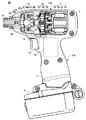
最初に、図1を参照して本発明の実施形態に係る電動工具全体について説明する。電動工具(インパクトドライバ)50は、後述するブラシレス直流モータ1の回転軸と同一方向(水平軸方向)に沿って、一端部(図面の右端部)から他端部(図面の左端部)に延在する胴体ハウジング部21aと、胴体ハウジング部21aより垂下するハンドルハウジング部21bとから構成された工具本体を含み、胴体ハウジング部21aの他端部に配置された先端工具保持部31には、図示されていないが、工具本体より回転打撃力を受けて、被加工部材にネジ(締付具)を締付けるドライバビット(先端工具)が着脱自在に装着される。先端工具としてドライバビットの変わりに、ボルト締付用ビットも装着することができる。すなわち、胴体ハウジング部21aの一端部には、駆動源となるブラシレス直流モータ1が装着され、胴体ハウジング部21aの他端部には回転打撃力を出力する先端工具保持部31に先端工具(図示なし)が着脱自在に装着される。
Initially, the whole electric tool which concerns on embodiment of this invention with reference to FIG. 1 is demonstrated. The electric tool (impact driver) 50 extends from one end portion (right end portion in the drawing) to the other end portion (left end portion in the drawing) along the same direction (horizontal axis direction) as the rotation axis of the
胴体ハウジング部21aの一端部側には、ブラシレス直流モータ1を駆動するためのインバータ部(回路基板)2が装着されている。胴体ハウジング部21aの中間部には、モータ1の回転軸方向に回転力を伝達する動力伝達機構部(減速機構部)22、前記回転打撃力を与えるインパクト機構部26、該インパクト機構部26の回転打撃力を先端工具へ伝達するアンビル30が装着されている。
An inverter part (circuit board) 2 for driving the
ハンドルハウジング部21bの下端部には、ブラシレス直流モータ1の駆動電源となる電池パック4が着脱可能に装着されている。また、電池パック4の上部には、モータ1のインバータ部2を制御するための制御回路部((回路基板)3が、紙面を横切る方向に延在するように設けられている。一方、ハンドルハウジング部21bの上端部にはトリガスイッチ部13が配設され、トリガスイッチ部13のトリガ操作部13aがバネ力によって付勢された状態でハンドルハウジング部21bから突出している。後述するように、トリガ操作部13aをバネ力に抗してハンドルハウジング部21b内方向へ把持することによって、トリガ押込量(操作量)を調整し、モータ1の回転数を制御することができる。
A battery pack 4 serving as a driving power source for the
電池パック4は、トリガスイッチ部13および制御回路部(回路基板)3へ駆動電源を供給し、かつインバータ部2へ駆動電力を供給するように電気的接続されている。
The battery pack 4 is electrically connected so as to supply drive power to the
ブラシレス直流モータ1の回転出力軸の回転力は、その回転出力軸のギヤ歯に係合された動力伝達機構部(減速機構部)22を介して、インパクト機構部26の一部を構成するスピンドル28に伝達される。動力伝達機構部(減速機構部)22は、ピニオンギヤ(サンギヤ)25と、そのピニオンギヤ25に噛合う二つの遊星ギヤ23とを含み、これらは胴体ハウジング部21a内のインナカバー(図示なし)内に組み込まれている。スピンドル28には、この減速機構部22によって、ブラシレス直流モータ1の回転に対し減速された回転力が与えられる。
The rotational force of the rotation output shaft of the
インパクト機構部26は、減速機構部22を介して回転力が与えられるスピンドル28と、スピンドル28に取付けられ、スピンドル28の回転軸方向に移動可能に係合し、回転打撃力を与えるハンマ27と、ハンマ27による回転打撃力で回転し、先端工具保持部31を有するアンビル30とを備える。ハンマ27およびアンビル30は、回転平面上の2箇所に互いに対称的に配置された2つのハンマ凸部(打撃部)27aおよび2つのアンビル凸部30aをそれぞれ有し、該ハンマ凸部27aおよびアンビル凸部30aは互いに回転方向に噛み合う位置にある。
The
これら凸部同士27aおよび30aの噛み合いにより、回転打撃力が伝えられる。さらに、上記ハンマ27は、スピンドル28を囲むリング域で、スピンドル28に対して軸方向に摺動自在にされていると共に、スプリング29によって軸方向前方へと付勢されている。ハンマ27の内周面には、逆V字型(略三角形)のカム溝27bが設けられている。一方、スピンドル28の外周面には軸方向に、V字型のカム溝28aが設けられており、このカム溝28aとハンマ27の内周カム溝27b間に挿入されたボール(鋼球)32を介してハンマ27が回転する。
The rotational striking force is transmitted by the engagement of the
インパクト機構部26において、被加工物へネジ等の締付具を回転させるための負荷トルクよりもハンマ27の回転トルクの方が小さいと、モータ1から与えられるスピンドル28の回転力は、ボール32を挟持するカム溝28aおよびカム溝27aを介してハンマ27に伝達され、スピンドル28およびハンマ27を一緒に回転させ始める。スピンドル28およびハンマ27は相対的にねじられることになり、ハンマ27は、スピンドルカム溝28aに沿って、スプリング29をねじりながら、図面右方向へ、圧縮しつつ後退し、ハンマ凸部27aがアンビル凸部30aとの結合から離れた時点から、ハンマ27はアンビル凸部30aの高さを乗り越えると、アンビル30との噛み合いが解ける。さらにハンマ27は、スプリング29による付勢とカム溝28aによるガイドを受けて、回転しつつ、図面左方向へ前進し、ハンマ凸部(打撃部)27aで回転前方のアンビル30のアンビル凸部30aに衝撃トルクを与える。この衝撃トルクは、後述するように、アンビル30の先端工具保持部31に取付けられた、先端工具(例えば、ドライバビット)(図示なし)へ伝わり、さらにドライバビットから締付具ネジに回転衝撃トルクを伝えて、被加工部材へのネジ込みもしくは締付けを行う。再びハンマ凸部27aおよびアンビル凸部30aが互いに係合することになるので、その後、再びハンマ27の後退が始まり、上記の打撃動作を繰返すことになる。
In the
次に、ブラシレス直流モータ1のインバータ回路部2および制御回路部3について、図2を参照して説明する。
Next, the
ブラシレス直流モータ1は、本実施形態では3相ブラシレス直流モータから成る。ブラシレス直流モータ1は、インナーロータ型で、一対のN極およびS極を含む永久磁石(マグネット)を埋め込んで構成された回転子(マグネットロータ)1bと、該マグネットロータ1bの回転位置を検出するために60°毎に配置された3つの回転位置検出素子(ホールIC)5、6、7と、回転位置検出素子を構成するホールIC5、6、7の位置検出信号に基づいて電気角120°の電流の通電区間に制御されるスター結線された固定子1cの3相巻線U、V、Wからなる電機子巻線1dとから構成される。なお、ブラシレス直流モータ1の回転子1bの回転位置検出手段(5、6、7)は、上記したようなホールICによって電磁結合的に検出する他に、固定子巻線1dの誘起起電圧(逆起電力)を、フィルタを通して論理信号として取出すことによって回転子位置を検出するセンサレス方式を採用することもできる。
The
インバータ部(電力変換器)2は、3相ブリッジ形式に接続された6個の絶縁ゲート・バイポーラ・トランジスタ(IGBT)Q1〜Q6と、トランジスタQ1〜Q6の各コレクタ−エミッタ間に内蔵されて並列接続されたフライホイールダイオード(図示なし)とから構成される。ブリッジ接続された6個のトランジスタQ1〜Q6の各ゲートはインバータ駆動部(インターフェイス部)8aに接続され、また、6個のトランジスタQ1〜Q6のコレクタまたはエミッタはスター結線された電機子巻線U、VおよびWに接続される。これによって、6個のトランジスタQ1〜Q6は、インバータ駆動部8aから入力されたスイッチング素子駆動信号(H4、H5、H6等の駆動信号)によってスイッチング動作を行い、インバータ部2に印加される電池パック4の直流電圧を、3相(U相、V相、W相)電圧Vu、Vv、Vwとして、電機子巻線U、V、Wへ電力を供給する。
The inverter unit (power converter) 2 is built in parallel between six insulated gate bipolar transistors (IGBTs) Q1 to Q6 connected in a three-phase bridge form, and between the collectors and emitters of the transistors Q1 to Q6. And a connected flywheel diode (not shown). The gates of the six transistors Q1 to Q6 connected in a bridge are connected to an inverter drive unit (interface unit) 8a, and the collectors or emitters of the six transistors Q1 to Q6 are star-connected armature windings U. , V and W. As a result, the six transistors Q1 to Q6 perform a switching operation according to the switching element drive signals (drive signals such as H4, H5, and H6) input from the
この場合、6個のトランジスタQ1〜Q6の各ゲートを駆動するスイッチング素子駆動信号(3相信号)のうち、3個の負電源側トランジスタQ4、Q5、Q6をパルス幅変調信号(PWM信号)H4、H5、H6として供給し、後述する制御回路部3によって、トリガスイッチ部13のトリガ押込量d(図4参照)の検出信号に基づいて、PWM信号のパルス幅(デューティ比)を変化させることによりモータ1への電力を調整し、モータの起動および速度を制御する。該PWM信号は、インバータ部2の正電源側スイッチング素子Q1〜Q3または負電源側スイッチング素子Q4〜Q6のいずれか一方側のスイッチング素子群に供給し、該スイッチング素子を高速スイッチングさせることにより、結果的に、電池パック4の直流電圧から各電機子巻線U、V、Wへ供給する電力を供給する。本実施形態では、上述したように、負電源側スイッチング素子群Q4〜Q6にPWM信号が供給される。従って、該PWM信号のパルス幅の制御によって各電機子巻線U、V、Wへ供給する電力を調整してモータ1の回転数を制御することができる。
In this case, among the switching element drive signals (three-phase signals) for driving the gates of the six transistors Q1 to Q6, the three negative power supply side transistors Q4, Q5, and Q6 are connected to the pulse width modulation signal (PWM signal) H4. , H5 and H6, and the pulse width (duty ratio) of the PWM signal is changed based on the detection signal of the trigger push-in amount d (see FIG. 4) of the
制御回路部3は、図示されていないが、処理プログラムとデータに基づいて駆動信号を出力するためのCPU、処理プログラムや制御データを記憶するためのROM、データを一時記憶するためのRAM、タイマ等を含むマイコンによって構成される。機能的にはインバータ部2の制御信号およびPWM信号を出力するための駆動信号形成部(CPUおよびメモリを含む)8と、駆動信号形成部8の出力信号に基づきインバータ部2を駆動するためのインバータ駆動部8aと、上記トリガスイッチ部13の操作量(トリガ押込量)に応答する出力信号(ポテンショメータの電圧信号)Vtに基づきトリガ押込量dを検出するトリガ押込量検出部10と、トリガ押込量検出部10により検出されたトリガ押込量に応答してブラシレス直流モータ1の印加電圧、すなわちインバータ駆動部8aの出力PWM信号のデューティ比を設定するための印加電圧設定部9と、モータの正逆切替レバー14(図1参照)による正方向回転または逆方向回転の操作を検出してモータ1の回転方向を設定するための回転方向設定部11と、上記3つの回転位置検出素子(ホールIC)5、6、7の出力信号に基づいて回転子1bと固定子1cの電機子巻線U、V、Wとの関係位置を検出するための回転位置検出部12とから構成される。
Although not shown, the control circuit unit 3 includes a CPU for outputting a drive signal based on the processing program and data, a ROM for storing the processing program and control data, a RAM for temporarily storing the data, and a timer. It is comprised by the microcomputer containing etc. Functionally, a drive signal forming unit (including a CPU and a memory) 8 for outputting a control signal and a PWM signal of the
駆動信号形成部(CPUおよびメモリを含む)8は、回転方向設定部11と回転子位置検出部12の出力信号に基づいて所定のスイッチング素子Q1〜Q6を交互にスイッチングするための駆動信号を形成し、インバータ駆動部8aへ出力する。これによって、電機子巻線1dの所定の巻線(U、V、W)を交互に通電して、回転子1bを設定した回転方向に回転させる。この場合、印加電圧設定部9の出力制御信号(データ)に基づいて、インバータ部2の負電源側スイッチング素子Q4〜Q6へ印加する駆動信号はPWM変調信号として出力される。もちろん、PWM変調信号は、上述したように、負電源側スイッチング素子Q4〜Q6へ印加する代わりに、正電源側スイッチング素子Q1〜Q3へ印加してもよい。
A drive signal forming unit (including a CPU and a memory) 8 forms a drive signal for alternately switching predetermined switching elements Q1 to Q6 based on output signals from the rotation
駆動信号形成部8によるPWM信号の作成は、ROMメモリに必要な制御データを予め記憶させておき、クロック信号に従って読み出してPWM作成データとして利用する。本発明によれば、後述するように、図5または図6に示すようなトリガスイッチ部13のトリガ押込量(電圧出力Vt)dとPWM信号のデューティ比DUTYとの関係が印加電圧設定部9に予め記憶されており、印加電圧設定部9の出力制御信号に応答してPWM信号のパルス幅(デューティ比)が可変される。
The PWM signal is generated by the drive
トリガスイッチ部13の構成例は、図3の構造図(a)および回路機能図(b)に示されるように、トリガスイッチ部13のトリガ操作部13aがバネ力によってトリガ押込方向と対向する方向に付勢されている。トリガ操作部13aをバネ力に対抗してトリガ押込方向(ハンドルハウジング部21b内方向)へ把持することによって、ポテンショメータVRの可動端子(摺動端子)Tmが移動し、ポテンショメータVRの可動端子Tmから検出される電圧Vtは高い電圧となる。これによって、トリガスイッチ13の押込量dは可動端子電圧Vtに変換される。図4の実線は、トリガ押込量dとポテンショメータVR1の可動端子電圧Vtの関係を示す。図4の破線に示すうに、トリガスイッチ押込量dに対して可動端子電圧Vtが減少するように構成してもよい。
The configuration example of the
以上の構成において、本発明に従って、印加電圧設定部9には、図5の(a)に示すように、トリガ押込量d対PWMデューティ比DUTY特性を記憶しておく。PWMデューティ比DUTYは、上述したインバータ駆動部8aから負電源側スイッチング素子Q4〜Q6の各ゲートに出力されるPWM信号H4、H5、H6のパルス幅のデューティ比を示す。すなわち、電機子巻線(U、V、W)を電気角120°通電するために各スイッチング素子(Q4〜Q6)のゲートに供給されるゲート駆動信号H4、H5、H6をパルス幅変調させるためのPWM信号のパルス幅のデューティ比を示す。
In the above configuration, according to the present invention, the applied
図5の(a)に示すトリガ押込量d対PWMデューティ比DUTY特性は、先端工具の操作性および作業効率の観点から予め実験的に求めてメモリに記憶しておく。図5の(a)に示す特性において、上限デューティ比DUTYmaxおよび下限デューティ比DUTYminは、図5の(b)に示すトリガ押込量d対モータ回転数N特性における上限回転数N2および下限回転数N1に制御するためのデューティ比に対応している。図5の(b)の特性は、図5の(a)の特性と同様に、先端工具の操作性および作業効率の観点から予め実験的に求めておき、メモリ部に記憶しておく。 The trigger push-in amount d vs. PWM duty ratio DUTY characteristic shown in FIG. 5A is experimentally obtained in advance from the viewpoint of the operability and work efficiency of the tip tool and stored in the memory. In the characteristics shown in FIG. 5A, the upper limit duty ratio DUTYmax and the lower limit duty ratio DUTYmin are the upper limit speed N2 and the lower limit speed N1 in the trigger push-in amount d versus the motor speed N characteristics shown in FIG. It corresponds to the duty ratio for controlling to. The characteristic shown in FIG. 5B is experimentally obtained in advance from the viewpoint of the operability and work efficiency of the tip tool and stored in the memory unit, similarly to the characteristic shown in FIG.
図5の(b)の特性において、トリガ操作部13aのトリガ押込量dが上記第1の押込量D1以下の第1の押込範囲(低速域押込範囲)d1(例えば、3mm)では、モータ1の回転数Nを、先端工具の負荷へ回転力を伝達するために必要な下限回転数N1(例えば、125rpm)と、先端工具の位置決め等の操作性を損なわない限度の上限回転数N2(例えば、250rpm)との第1回転数範囲内において、所定の第1回転数上昇率で上昇させるようにPWM変調信号のデューティ比を、図5の(a)におけるデューティ比DUTYmax(例えば、10%)およびDUTYmin(例えば、5%)に制御する。
In the characteristic shown in FIG. 5B, in the first pushing range (low speed pushing range) d1 (for example, 3 mm) where the trigger pushing amount d of the
また、図5の(b)に示すように、トリガ操作部13aのトリガ押込量dが、上記第1の押込量D1を超えて最大の押込量Dm(例えば、12.5mm)に至る第2の押込範囲(高速域押込範囲)d2(例えば、9.5mm)内では、モータ1の回転数Nを、上限回転数N2と全速回転数Nm(例えば、2500rpm)との第2回転数範囲内において、第1押込範囲d1における前記第1回転数上昇率(ΔN1/ΔD1)より高い第2の回転数上昇率(ΔN2/ΔD2)で上昇させるように、図5の(a)に示したトリガ押込量dに応答してPWM信号のデューティ比(DUTY)を制御する。すなわち、トリガ操作部13aのトリガ押込量dが第1の押込範囲(低速域押込範囲)d1にある場合は、モータ回転数Nを、N1〜N2の範囲に低く設定して位置決め等の操作性を向上させ、トリガ押込量dが第2の押込範囲(高速域押込範囲)d2にある場合は、モータ回転数Nの上昇率(ΔN2/ΔD2)を、第1押込範囲d1のモータ回転数Nの上昇率(ΔN1/ΔD1)より大きくしてネジ締め作業等の作業効率を向上させる。
Further, as shown in FIG. 5 (b), the trigger pushing amount d of the
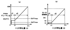
上記実施態様において、トリガ操作部13aの第1の押込範囲d1におけるトリガ押込量dに対するモータ回転数Nは、図6の(a)および(b)に示すように、上記上限回転数N2と下限回転数N1の範囲内で一定回転数となるように、PWM信号のデューティ比DUTYを一定に制御してもよい。
In the above embodiment, the motor rotation speed N with respect to the trigger pressing amount d in the first pressing range d1 of the
なお、トリガ押込量dは、図4に示すように、ポテンショメータVRによって端子電圧Vtとして電気量に変換されて検出されるので、例えば、最大押込量Dmのときの検出電圧Vtは5Vに設定される。印加電圧設定部9は、トリガスイッチ部13のトリガ押込量dに基づくポテンショメータVRの出力電圧Vtに対応して、予め記憶された図5の(a)または図6の(a)に示す特性に従ってPWM信号のデューティ比DUTYを出力する。
As shown in FIG. 4, the trigger push-in amount d is detected by being converted into an electric amount as a terminal voltage Vt by the potentiometer VR. For example, the detection voltage Vt at the maximum push-in amount Dm is set to 5V. The The applied
以上の構成において、電動工具50のトリガスイッチ13のトリガ操作部13aを把持すると、トリガ押込量dが図5に示した第1の押込範囲d1において、モータ1は回転を開始し、トリガ押込量dをD1以下に把持すると、負電源側スイッチング素子Q4〜Q6(または正電源側スイッチング素子Q1〜Q3)は、PWM変調信号H4〜H6のパルス幅のデューティ比がDUTYmin〜DUTYmaxの範囲に制御されるので、モータ1の回転数Nは上限回転数N2〜下限回転数N1の範囲に制御される。
In the above configuration, when the
従って、ドライバビット等の先端工具の被加工部材に対する位置決め操作等の作業開始時の操作を有利にする。例えば、DUTYmin以上でPWM制御すれば、電機子巻線1dに印加される印加電圧が小さくなることを防止して回転数Nを下限回転数N1以上とすることができる。これによって、先端工具にかかる負荷トルクの影響で、モータ1の回転子1aが回転不能となることを防止できる。逆に、DUTYmax以下のPWM信号とすれば、電機子巻線1dの印加電圧が過大電圧となることを防止してモータ回転数Nを上限回転数N2以下に制御できる。これによって、モータ回転数の急激な上昇を防止し、位置決め箇所から電動工具の先端工具が外れてしまい、先端工具が被加工部材を損傷するという問題を防止できる。つまり、トリガスイッチ13のトリガ操作の開始時には、PWM信号のデューティ比DUTYをDUTYmaxからDUTYminの範囲内に設定することにより作業開始時における低速域押込範囲d1の操作に有効な低速領域を容易に得ることができる。
Therefore, it is advantageous to perform an operation at the start of work such as a positioning operation for a workpiece of a tip tool such as a driver bit. For example, if PWM control is performed at DUTYmin or higher, it is possible to prevent the applied voltage applied to the armature winding 1d from being reduced and to set the rotational speed N to the lower limit rotational speed N1 or higher. As a result, the
また、もし上述したような従来のトリガ制御方式に従うとすれば、低速域押込範囲d1でのモータの回転数上昇率が高速域押込範囲d2と同様に高くなるので、トリガスイッチ13のトリガ押込量dを小さくして低回転数を保持し続けるための微妙な操作が要求される。このため、トリガスイッチ操作が難しく、トリガ押込量の変動により先端工具の動作が不安定になるという問題を招くことになる。しかし、本発明のトリガ制御方式によれば、トリガスイッチ13のトリガ押込量dが押込開始から所定の押込量D1までの低速域押込範囲d1内では、回転数N2以下の低速領域でブラシレス直流モータ1を制御することになるので、トリガスイッチ13の操作による低速領域でのモータの回転制御を容易にできる。
Further, if the conventional trigger control method as described above is followed, the rate of increase in the motor speed in the low speed region push range d1 becomes as high as that in the high speed region push range d2, so that the trigger push amount of the
トリガスイッチ13のトリガ押込量dが、所定の押込量D1以上の高速域押込範囲d2内になると、押込量に対する回転上昇率が上昇し、短時間にモータの回転数Nを最大回転数Nmに制御することができる。これによって、作業効率を向上させることができる。
When the trigger push amount d of the
図6に示すように、トリガスイッチ13のトリガ押込量dが低速域押込範囲d1内において、PWM信号のパルス幅のデューティ比を一定に制御してモータ回転数を定速制御する場合は、モータ回転数が変動しないので、操作性をさらに向上させることができる。
As shown in FIG. 6, when the trigger pressing amount d of the
以上の実施形態の説明から明らかにされるように、本発明によれば、モータの回転開始時における回転数の制御を容易にし、電動工具の操作性を向上させることができる。 As will be apparent from the above description of the embodiment, according to the present invention, it is possible to easily control the rotational speed at the start of rotation of the motor and to improve the operability of the electric tool.
なお、以上の実施形態では、3相ブラシレス直流モータを使用した電動工具について説明したが、3相以外のブラシレス直流モータを使用した電動工具についても適用することができる。また、本発明は、インパクトドライバに限らず、電動ドリル等の電動回転工具に適用することもできる。 In addition, although the above embodiment demonstrated the electric tool using a three-phase brushless DC motor, it can be applied also to the electric tool using a brushless DC motor other than three phases. Further, the present invention can be applied not only to an impact driver but also to an electric rotary tool such as an electric drill.
以上、本発明者によってなされた発明を実施形態に基づき具体的に説明したが、本発明は上記実施形態に限定されるものではなく、その要旨を逸脱しない範囲内で種々の変更が可能である。 As mentioned above, the invention made by the present inventor has been specifically described based on the embodiment. However, the present invention is not limited to the embodiment described above, and various modifications can be made without departing from the scope of the invention. .
1:ブラシレス直流モータ 1a:回転子(マグネットロータ)
1b:永久磁石 1c:固定子 1d:固定子巻線 2:インバータ部
3:制御回路部 4:電池パック 5、6、7:回転位置検出素子(ホールIC)
8:駆動信号形成部 8a:インバータ駆動部 9:印加電圧設定部
10:トリガ押込量検出部 11:回転方向設定部 12:回転位置検出部
13:トリガスイッチ 13a:トリガ操作部 14:正逆切替レバー
21a:胴体ハウジング部 21b:ハンドルハウジング部
22:動力伝達機構部(減速機構部) 23:遊星ギヤ 24:リングギヤ
25:ピニオンギヤ 26:インパクト機構部 27:ハンマ
27a:ハンマ凸部 27b:ハンマ内周面のカム溝 28:スピンドル
28a:スピンドル外周面のカム溝 29:バネ 30:アンビル
30a:アンビル凸部 31:先端工具保持部 32:ボール(鋼球)
50:電動工具 d1:第1の押込範囲(低速域押込範囲)
d2:第2の押込範囲(高速域押込範囲) DUTYmax:上限デューティ比
DUTYmin:下限デューティ比 N1:下限回転数 N2:上限回転数
U、V、W:3相固定子巻線
1:
1b: Permanent magnet 1c: Stator 1d: Stator winding 2: Inverter unit 3: Control circuit unit 4: Battery pack 5, 6, 7: Rotation position detection element (Hall IC)
8: Drive
50: Electric tool d1: First push range (low speed range push range)
d2: Second push range (high-speed push range) DUTYmax: Upper limit duty ratio DUTYmin: Lower limit duty ratio N1: Lower limit rotation speed N2: Upper limit rotation speed U, V, W: Three-phase stator winding
Claims (5)
前記制御回路部は、前記トリガスイッチ部の前記トリガ押込量が第1の押込量以下の第1の押込範囲では、前記電動モータの回転数を、前記先端工具の負荷へ回転力を伝達するための下限回転数と、前記全速回転数より低い先端工具の操作性によって規定される上限回転数との間の第1の回転数範囲内において、所定の第1の回転数上昇率で上昇させるか、または一定回転数となるように前記トリガ押込量に応答して制御し、かつ、
前記トリガスイッチ部の前記トリガ押込量が前記第1の押込量を超えて最大の押込量に至る第2の押込範囲内では、前記電動モータの回転数を、前記上限回転数と前記全速回転数との間の第2の回転数範囲内において、前記第1の押込範囲における前記第1の回転数上昇率より高い第2の回転数上昇率で上昇させるように前記トリガ押込量に応答して制御することを特徴とする電動工具。 An electric motor mounted in the housing part, a tip tool provided in the housing part that is rotationally driven by the electric motor, a trigger switch part provided in the housing part, and a trigger pushing amount of the trigger switch part In the electric tool having a control circuit unit for controlling the rotation speed of the electric motor from the rotation start to the full speed rotation speed,
The control circuit unit transmits the rotational force of the electric motor to the load of the tip tool in a first pressing range in which the trigger pressing amount of the trigger switch unit is equal to or less than the first pressing amount. In the first rotation speed range between the lower limit rotation speed of the first rotation speed and the upper limit rotation speed defined by the operability of the tip tool lower than the full speed rotation speed. Or in response to the trigger pressing amount so as to be a constant rotation speed, and
In the second pushing range in which the trigger pushing amount of the trigger switch unit exceeds the first pushing amount and reaches the maximum pushing amount, the rotation speed of the electric motor is set to the upper limit rotation speed and the full speed rotation speed. In response to the trigger push-in amount so as to increase at a second rotational speed increase rate higher than the first rotational speed increase rate in the first push-in range. An electric tool characterized by controlling.
前記制御回路部は、前記トリガスイッチ部の前記トリガ押込量が第1の押込量以下の第1の押込範囲では、前記電動モータの回転数を、前記先端工具の負荷へ回転力を伝達するための下限回転数と、前記全速回転数より低い先端工具の操作性によって規定される上限回転数との間の第1の回転数範囲内において、所定の第1の回転数上昇率で上昇させるか、または一定回転数となるように、前記トリガ押込量に応答して前記複数のスイッチング素子を駆動する前記パルス幅変調信号のデューティ比を制御し、かつ、
前記トリガスイッチ部の前記トリガ押込量が前記第1の押込量を超えて最大の押込量に至る第2の押込範囲内では、前記ブラシレス直流モータの回転数を、前記上限回転数と前記全速回転数との間の第2の回転数範囲内において、前記第1の押込範囲における前記第1の回転数上昇率より高い第2の回転数上昇率で上昇させるように、前記トリガ押込量に応答して前記複数のスイッチング素子を駆動する前記パルス幅変調信号のデューティ比を制御することを特徴とする電動工具。 A brushless DC motor having a rotor with a permanent magnet and a stator with a multi-phase armature winding, and a plurality of bridge-connected switching elements, and switching each DC voltage by switching DC voltage An inverter for supplying power to the armature winding, an inverter drive unit for driving the plurality of switching elements with a pulse width modulation signal, and a trigger for controlling the rotation speed of the brushless DC motor by a trigger pushing amount of a trigger operation A switch, a control circuit unit for controlling the rotation speed of the brushless DC motor from the rotation start to the full speed rotation speed based on a trigger pushing amount of the trigger switch unit, and a rotation transmission mechanism unit by the brushless DC motor. In an electric tool comprising a tip tool that is rotationally driven,
The control circuit unit transmits the rotational force of the electric motor to the load of the tip tool in a first pressing range in which the trigger pressing amount of the trigger switch unit is equal to or less than the first pressing amount. In the first rotation speed range between the lower limit rotation speed of the first rotation speed and the upper limit rotation speed defined by the operability of the tip tool lower than the full speed rotation speed. Or to control the duty ratio of the pulse width modulation signal that drives the plurality of switching elements in response to the trigger pressing amount so as to be a constant rotational speed, and
In the second pressing range in which the trigger pressing amount of the trigger switch unit exceeds the first pressing amount and reaches the maximum pressing amount, the rotation speed of the brushless DC motor is set to the upper limit rotation speed and the full speed rotation. In response to the trigger push-in amount so as to increase at a second rotational speed increase rate higher than the first rotational speed increase rate in the first push-in range within a second rotational speed range between And controlling a duty ratio of the pulse width modulation signal for driving the plurality of switching elements.
Priority Applications (1)
| Application Number | Priority Date | Filing Date | Title |
|---|---|---|---|
| JP2007144689A JP2008296323A (en) | 2007-05-31 | 2007-05-31 | Power tool |
Applications Claiming Priority (1)
| Application Number | Priority Date | Filing Date | Title |
|---|---|---|---|
| JP2007144689A JP2008296323A (en) | 2007-05-31 | 2007-05-31 | Power tool |
Publications (2)
| Publication Number | Publication Date |
|---|---|
| JP2008296323A true JP2008296323A (en) | 2008-12-11 |
| JP2008296323A5 JP2008296323A5 (en) | 2010-06-24 |
Family
ID=40170327
Family Applications (1)
| Application Number | Title | Priority Date | Filing Date |
|---|---|---|---|
| JP2007144689A Pending JP2008296323A (en) | 2007-05-31 | 2007-05-31 | Power tool |
Country Status (1)
| Country | Link |
|---|---|
| JP (1) | JP2008296323A (en) |
Cited By (7)
| Publication number | Priority date | Publication date | Assignee | Title |
|---|---|---|---|---|
| JP2010179378A (en) * | 2009-02-03 | 2010-08-19 | Makita Corp | Screw fastening tool |
| WO2011058895A1 (en) * | 2009-11-11 | 2011-05-19 | 株式会社マキタ | Power tool |
| US20120068633A1 (en) * | 2010-09-17 | 2012-03-22 | Makita Corporation | Variable speed switch and electric power tool with the variable speed switch mounted thereto |
| JP2012157942A (en) * | 2011-02-01 | 2012-08-23 | Hitachi Koki Co Ltd | Electric power tool |
| JP2012210687A (en) * | 2011-03-31 | 2012-11-01 | Makita Corp | Power tool |
| JP2015009284A (en) * | 2013-06-26 | 2015-01-19 | 株式会社マキタ | Electric power tool |
| CN110869170A (en) * | 2017-09-29 | 2020-03-06 | 工机控股株式会社 | Electric tool |
Citations (4)
| Publication number | Priority date | Publication date | Assignee | Title |
|---|---|---|---|---|
| JP2001129768A (en) * | 1999-10-29 | 2001-05-15 | Matsushita Electric Works Ltd | Impact rotation tool |
| JP2003311653A (en) * | 2002-04-23 | 2003-11-05 | Matsushita Electric Works Ltd | Power tool |
| JP2005169535A (en) * | 2003-12-09 | 2005-06-30 | Matsushita Electric Works Ltd | Power tool |
| JP2006221908A (en) * | 2005-02-09 | 2006-08-24 | Satori S-Tech Co Ltd | Trigger switch circuit |
-
2007
- 2007-05-31 JP JP2007144689A patent/JP2008296323A/en active Pending
Patent Citations (4)
| Publication number | Priority date | Publication date | Assignee | Title |
|---|---|---|---|---|
| JP2001129768A (en) * | 1999-10-29 | 2001-05-15 | Matsushita Electric Works Ltd | Impact rotation tool |
| JP2003311653A (en) * | 2002-04-23 | 2003-11-05 | Matsushita Electric Works Ltd | Power tool |
| JP2005169535A (en) * | 2003-12-09 | 2005-06-30 | Matsushita Electric Works Ltd | Power tool |
| JP2006221908A (en) * | 2005-02-09 | 2006-08-24 | Satori S-Tech Co Ltd | Trigger switch circuit |
Cited By (14)
| Publication number | Priority date | Publication date | Assignee | Title |
|---|---|---|---|---|
| JP2010179378A (en) * | 2009-02-03 | 2010-08-19 | Makita Corp | Screw fastening tool |
| US9314914B2 (en) | 2009-11-11 | 2016-04-19 | Makita Corporation | Power tool |
| WO2011058895A1 (en) * | 2009-11-11 | 2011-05-19 | 株式会社マキタ | Power tool |
| JP2011101932A (en) * | 2009-11-11 | 2011-05-26 | Makita Corp | Power tool |
| CN102596514A (en) * | 2009-11-11 | 2012-07-18 | 株式会社牧田 | Power tool |
| US20120068633A1 (en) * | 2010-09-17 | 2012-03-22 | Makita Corporation | Variable speed switch and electric power tool with the variable speed switch mounted thereto |
| US8698430B2 (en) * | 2010-09-17 | 2014-04-15 | Makita Corporation | Variable speed switch and electric power tool with the variable speed switch mounted thereto |
| US9444307B2 (en) | 2010-09-17 | 2016-09-13 | Makita Corporation | Variable speed switch and electric power tool with the variable speed switch mounted thereto |
| JP2012157942A (en) * | 2011-02-01 | 2012-08-23 | Hitachi Koki Co Ltd | Electric power tool |
| JP2012210687A (en) * | 2011-03-31 | 2012-11-01 | Makita Corp | Power tool |
| JP2015009284A (en) * | 2013-06-26 | 2015-01-19 | 株式会社マキタ | Electric power tool |
| CN110869170A (en) * | 2017-09-29 | 2020-03-06 | 工机控股株式会社 | Electric tool |
| US11731256B2 (en) | 2017-09-29 | 2023-08-22 | Koki Holdings Co., Ltd. | Electric tool |
| CN110869170B (en) * | 2017-09-29 | 2023-09-29 | 工机控股株式会社 | Electric tool |
Similar Documents
| Publication | Publication Date | Title |
|---|---|---|
| JP5333881B2 (en) | Electric tool | |
| JP5527569B2 (en) | Impact tools | |
| JP5360344B2 (en) | Electric tool | |
| JP5182562B2 (en) | Electric tool | |
| CN102300677B (en) | Electric boring tool | |
| JP5115904B2 (en) | Impact tools | |
| US8074731B2 (en) | Impact tool | |
| US10171011B2 (en) | Electric tool | |
| JP2008296323A (en) | Power tool | |
| WO2013183433A1 (en) | Power tool | |
| CN109382779B (en) | Electric working machine | |
| JP6513006B2 (en) | Motor control device | |
| JP6090581B2 (en) | Electric tool | |
| US20120073846A1 (en) | Power tool | |
| JP2011016210A (en) | Power tool | |
| WO2015093056A1 (en) | Motor-drive controlling device, power tool, and motor-drive controlling method | |
| JP5381390B2 (en) | Electric tool | |
| JP2006315117A (en) | Cordless power tool | |
| JP2017205834A (en) | Electric work machine | |
| JP2013146847A (en) | Impact tool | |
| WO2021100368A1 (en) | Impact tool, impact tool control method and program | |
| JP2015009289A (en) | Electric tool | |
| JP5954386B2 (en) | Electric tool | |
| JP2017216787A (en) | tool | |
| JP2009220214A (en) | Power tool |
Legal Events
| Date | Code | Title | Description |
|---|---|---|---|
| A521 | Request for written amendment filed |
Free format text: JAPANESE INTERMEDIATE CODE: A523 Effective date: 20100506 |
|
| A621 | Written request for application examination |
Free format text: JAPANESE INTERMEDIATE CODE: A621 Effective date: 20100506 |
|
| A977 | Report on retrieval |
Free format text: JAPANESE INTERMEDIATE CODE: A971007 Effective date: 20120522 |
|
| A131 | Notification of reasons for refusal |
Free format text: JAPANESE INTERMEDIATE CODE: A131 Effective date: 20120531 |
|
| A521 | Request for written amendment filed |
Free format text: JAPANESE INTERMEDIATE CODE: A523 Effective date: 20120727 |
|
| A02 | Decision of refusal |
Free format text: JAPANESE INTERMEDIATE CODE: A02 Effective date: 20130207 |