JP2008294435A - Transformer core and coriolis flowmeter having the same - Google Patents
Transformer core and coriolis flowmeter having the same Download PDFInfo
- Publication number
- JP2008294435A JP2008294435A JP2008118139A JP2008118139A JP2008294435A JP 2008294435 A JP2008294435 A JP 2008294435A JP 2008118139 A JP2008118139 A JP 2008118139A JP 2008118139 A JP2008118139 A JP 2008118139A JP 2008294435 A JP2008294435 A JP 2008294435A
- Authority
- JP
- Japan
- Prior art keywords
- core
- steel plate
- transformer core
- transformer
- sub
- Prior art date
- Legal status (The legal status is an assumption and is not a legal conclusion. Google has not performed a legal analysis and makes no representation as to the accuracy of the status listed.)
- Pending
Links
Images
Classifications
-
- H—ELECTRICITY
- H01—ELECTRIC ELEMENTS
- H01F—MAGNETS; INDUCTANCES; TRANSFORMERS; SELECTION OF MATERIALS FOR THEIR MAGNETIC PROPERTIES
- H01F27/00—Details of transformers or inductances, in general
- H01F27/24—Magnetic cores
- H01F27/245—Magnetic cores made from sheets, e.g. grain-oriented
-
- G—PHYSICS
- G01—MEASURING; TESTING
- G01F—MEASURING VOLUME, VOLUME FLOW, MASS FLOW OR LIQUID LEVEL; METERING BY VOLUME
- G01F1/00—Measuring the volume flow or mass flow of fluid or fluent solid material wherein the fluid passes through a meter in a continuous flow
- G01F1/76—Devices for measuring mass flow of a fluid or a fluent solid material
- G01F1/78—Direct mass flowmeters
- G01F1/80—Direct mass flowmeters operating by measuring pressure, force, momentum, or frequency of a fluid flow to which a rotational movement has been imparted
- G01F1/84—Coriolis or gyroscopic mass flowmeters
- G01F1/8409—Coriolis or gyroscopic mass flowmeters constructional details
- G01F1/8413—Coriolis or gyroscopic mass flowmeters constructional details means for influencing the flowmeter's motional or vibrational behaviour, e.g., conduit support or fixing means, or conduit attachments
-
- G—PHYSICS
- G01—MEASURING; TESTING
- G01F—MEASURING VOLUME, VOLUME FLOW, MASS FLOW OR LIQUID LEVEL; METERING BY VOLUME
- G01F1/00—Measuring the volume flow or mass flow of fluid or fluent solid material wherein the fluid passes through a meter in a continuous flow
- G01F1/76—Devices for measuring mass flow of a fluid or a fluent solid material
- G01F1/78—Direct mass flowmeters
- G01F1/80—Direct mass flowmeters operating by measuring pressure, force, momentum, or frequency of a fluid flow to which a rotational movement has been imparted
- G01F1/84—Coriolis or gyroscopic mass flowmeters
- G01F1/8409—Coriolis or gyroscopic mass flowmeters constructional details
- G01F1/8422—Coriolis or gyroscopic mass flowmeters constructional details exciters
-
- G—PHYSICS
- G01—MEASURING; TESTING
- G01F—MEASURING VOLUME, VOLUME FLOW, MASS FLOW OR LIQUID LEVEL; METERING BY VOLUME
- G01F1/00—Measuring the volume flow or mass flow of fluid or fluent solid material wherein the fluid passes through a meter in a continuous flow
- G01F1/76—Devices for measuring mass flow of a fluid or a fluent solid material
- G01F1/78—Direct mass flowmeters
- G01F1/80—Direct mass flowmeters operating by measuring pressure, force, momentum, or frequency of a fluid flow to which a rotational movement has been imparted
- G01F1/84—Coriolis or gyroscopic mass flowmeters
- G01F1/845—Coriolis or gyroscopic mass flowmeters arrangements of measuring means, e.g., of measuring conduits
- G01F1/8468—Coriolis or gyroscopic mass flowmeters arrangements of measuring means, e.g., of measuring conduits vibrating measuring conduits
- G01F1/8481—Coriolis or gyroscopic mass flowmeters arrangements of measuring means, e.g., of measuring conduits vibrating measuring conduits having loop-shaped measuring conduits, e.g. the measuring conduits form a loop with a crossing point
- G01F1/8486—Coriolis or gyroscopic mass flowmeters arrangements of measuring means, e.g., of measuring conduits vibrating measuring conduits having loop-shaped measuring conduits, e.g. the measuring conduits form a loop with a crossing point with multiple measuring conduits
-
- H—ELECTRICITY
- H01—ELECTRIC ELEMENTS
- H01F—MAGNETS; INDUCTANCES; TRANSFORMERS; SELECTION OF MATERIALS FOR THEIR MAGNETIC PROPERTIES
- H01F3/00—Cores, Yokes, or armatures
- H01F3/02—Cores, Yokes, or armatures made from sheets
-
- H—ELECTRICITY
- H01—ELECTRIC ELEMENTS
- H01F—MAGNETS; INDUCTANCES; TRANSFORMERS; SELECTION OF MATERIALS FOR THEIR MAGNETIC PROPERTIES
- H01F3/00—Cores, Yokes, or armatures
- H01F3/10—Composite arrangements of magnetic circuits
- H01F3/14—Constrictions; Gaps, e.g. air-gaps
Landscapes
- Physics & Mathematics (AREA)
- Fluid Mechanics (AREA)
- General Physics & Mathematics (AREA)
- Engineering & Computer Science (AREA)
- Power Engineering (AREA)
- Measuring Volume Flow (AREA)
- Transformers For Measuring Instruments (AREA)
Abstract
Description
本発明は、透磁性材料で作られた平坦な板面を有するコア鋼板(積層される鋼板)を複数積層し、各コア鋼板が少なくとも一つの開口を形成するように第一そして第二副鋼板部材から成るトランス用コアに関する。 The present invention provides a first and second sub-steel plate in which a plurality of core steel plates (laminated steel plates) made of a magnetically permeable material are laminated and each core steel plate forms at least one opening. The present invention relates to a transformer core composed of members.
軟磁性材料(あるいは透磁性材料)のコア鋼板を積層してトランス用コアを作ることは、トランスを製造する上で通常の技術である。トランス用コア内での漂遊磁界を最小とすること、あるいは磁力線が平行に流れて渦電流が最小となるようにすることを、目標とされている。 Laminating a core steel plate made of soft magnetic material (or magnetically permeable material) to make a transformer core is a common technique for manufacturing a transformer. The goal is to minimize the stray magnetic field in the transformer core or to minimize the eddy current by flowing the magnetic field lines in parallel.
トランスの現状の製造方法では、U型そしてI型の鋼板部材を互い違いに積層している。U型の鋼板部材は、組立工程において、上記U型の一方の脚部そして他方の脚部から電気コイルに挿入される。
この現状の製造方法において、大きな欠点は、製造誤差に起因してU型そしてI型の鋼板部材の接合縁同士が決して完璧には接合しないために、両鋼板部材の接合縁に空隙が生じてしまうことである。このような位置関係では、結果として、一方の脚部での接合縁を良く接触させると、製造誤差のために他方の接合縁では隙間が生じてしまうことがある。すなわち、接合縁は、半分だけ有効に機能する。接合縁はトランス用コア全体を通る磁束の飽和を決定する。 In this current manufacturing method, a major drawback is that the joining edges of the U-shaped and I-shaped steel plate members are never perfectly joined to each other due to a manufacturing error, resulting in a gap at the joining edges of both steel plate members. It is to end. In such a positional relationship, as a result, if the joint edge at one leg is in good contact, a gap may occur at the other joint edge due to manufacturing errors. That is, the joint edge functions effectively by half. The junction edge determines the saturation of the magnetic flux through the entire transformer core.
U型とI型の鋼板部材を同様に積層する他の従来技術は、接合縁を研磨して平坦な面に仕上げ、接合手段を用いて互いに最終接合させる方法である。これは、労力を要し、したがって費用も嵩む。 Another conventional technique for similarly laminating U-type and I-type steel plate members is a method in which the joining edge is polished to a flat surface and finally joined together using a joining means. This is labor intensive and therefore expensive.
本発明の目的とするところは、このような問題を一つでも解決しようとすることである。 The object of the present invention is to solve even one such problem.
このような目的は、本発明によると、各コア鋼板の副鋼板部材が、開口の両側にてコア鋼板の中心線に対して傾斜せる第一そして第二接合縁同士で接合されていることを特徴とするトランス用コアによって達成される。 Such an object is that according to the present invention, the secondary steel plate members of each core steel plate are joined at the first and second joining edges that are inclined with respect to the center line of the core steel plate on both sides of the opening. Achieved by the featured transformer core.
本発明の形態では、積層されるコア鋼板が二つに分割されて、斜接合縁をもつ二つの副鋼板部材で形成され、このコア鋼板が互い違いに積層される。二つの副鋼板部材は斜接合縁で補完し合う形でなくてはならなく、すなわち、互いに適合する。これらは、同一形状でも異なる形状でも実現できる。 In the embodiment of the present invention, the core steel plates to be laminated are divided into two parts and formed by two sub steel plate members having oblique joint edges, and the core steel plates are laminated alternately. The two sub-steel members must be complementary with each other at the beveled edges, i.e. they are compatible with each other. These can be realized in the same shape or in different shapes.
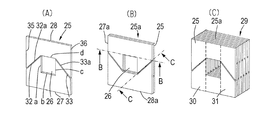
この斜接合縁の第一の利点は、長い接合縁を得られることである。図2(B)は直角な方向の接合縁で分割される場合をB−B線で示し、斜接合縁で分割されていることをC−C線で示している。後者の場合、磁束が通るのに有効な接合縁の長さは中心線に対して直角方向に延びる従来の接合縁の長さに比し、斜接合縁の角度が45°のとき、√2倍である。 The first advantage of this oblique joint edge is that a long joint edge can be obtained. FIG. 2B shows the case of being divided at a joining edge in a direction perpendicular to the line B-B, and shows that it is divided at the oblique joining edge by a line CC. In the latter case, the length of the joint edge effective for passing the magnetic flux is √2 when the angle of the oblique joint edge is 45 ° as compared with the length of the conventional joint edge extending in the direction perpendicular to the center line. Is double.
斜接合縁の第二の利点は、自己センタリング性である。本発明の一形態では、開口の両側における斜接合縁は、第一そして第二副鋼板部材を接合したときに中心線に対して自己センタリングされるように形成されていることを特徴とする。斜接合縁での分割は、二つのコア半体を接合するときに自己センタリングを可能とする。 The second advantage of the beveled edge is self-centering. In one aspect of the present invention, the oblique joining edges on both sides of the opening are formed so as to be self-centered with respect to the center line when the first and second secondary steel plate members are joined. The division at the oblique joining edge allows self-centering when joining the two core halves.
斜接合縁での分割の第三の利点は、組立てそして分解を容易とすることである。トランス用コアの二つのコア半体のそれぞれは、互い違いに積層された副鋼板部材が(例えばレーザ溶接により)パックとして保持されていて、櫛歯状に配置された斜接合縁を利用して嵌合してクランプ接合されたりあるいはその状態から引き離されたりできる。これは、例えば、コリオリ管がトランス用コアの開口を貫通して組み込まれるコリオリ型流量計におけるトランス用コアの組立時に、損傷しやすいコリオリ管がそのハウジングに収められた後まで上部のコア半体が組まれる必要がないので、好都合である。しかる後、二つのコア半体がクランプ接合されて、それ以上の結合手段なしでも、一体をなすようなる。 A third advantage of splitting at the beveled edge is that it facilitates assembly and disassembly. Each of the two core halves of the transformer core has sub-steel members that are alternately stacked and held as a pack (for example, by laser welding), and is fitted using oblique joint edges arranged in a comb shape. They can be clamped together or pulled away from that state. This is because, for example, when the core for transformer is assembled in a Coriolis type flow meter in which the Coriolis pipe is incorporated through the opening of the transformer core, the upper half of the core is placed after the Coriolis pipe, which is easily damaged, is housed in the housing. Is not necessary to be assembled. Thereafter, the two core halves are clamped together so that they can be integrated without further coupling means.
本発明の一形態では、少なくとも第一副鋼板部材がU字状をなし、端部で接合縁を形成する二つの脚部を有し、該接合縁が脚部の延出方向に対し傾斜している。 In one form of the present invention, at least the first auxiliary steel plate member has a U shape and has two leg portions that form a joining edge at the end, and the joining edge is inclined with respect to the extending direction of the leg portion. ing.
好ましくは、接合縁は中心線に対し30°と60°の間の角度、さらに好ましくは、40°の角度をなしている。 Preferably, the joining edge is at an angle between 30 ° and 60 °, more preferably 40 ° with respect to the centerline.
これは、一般的形態として好ましく、脚部が延びる方向に対して直角をなして最短の接合縁長の従来のものよりも大きい接合縁長をもつように分割する(直線もしくは曲線の斜接合縁をもつ二つの副鋼板部材が用いられる。もっと複雑な形であっても、打ち抜き加工あるいはレーザ切断加工により得ることができる。 This is preferable as a general form, and is divided so as to be perpendicular to the direction in which the legs extend and to have a joining edge length that is greater than the conventional one with the shortest joining edge length (straight or curved oblique joining edges). Two sub-steel members having the following are used: even more complicated shapes can be obtained by stamping or laser cutting.
斜接合縁でのコア鋼板の分割は、E型そしてI型副鋼板部材(図6参照)で成るコア鋼板積層で、電流あるいは電圧変換のために、二つのループコアをなすように二つの開口を有するトランス用コアにも適用可能である。 The core steel sheet is divided at the slanted joint edge by laminating core steel sheets composed of E-type and I-type sub-steel members (see Fig. 6). For current or voltage conversion, two openings are formed to form two loop cores. The present invention can also be applied to a transformer core having the same.
本発明で効果を確保するためには、コア鋼板を形成する二つの副鋼板部材の接合縁が脚部の延出方向(接合方向)に対して直角な方向に延びていないことが重要である。こうする際に、積層時に互いに隣接して板面で接面する副鋼板部材の接合縁同士が異なる線をなしていることである。接合縁同士はコア鋼板の板面上で交差していることも交差していないこともあり、あるいは例えば平行であったりする。交差するようにした場合、コア半体同士を接合してクランプする際の接合方向でのクランプ長が短くてすむという利点があり、これは、接合時の互いの嵌挿を容易とし、あるいは取外しも容易とする。非交差の場合は、トランス用コアの大きさそして組立条件に応じて、接合方向でのクランプ長が長くすることができ、クランプの信頼性が高まる。 In order to ensure the effect of the present invention, it is important that the joining edges of the two sub steel plate members forming the core steel plate do not extend in a direction perpendicular to the extending direction (joining direction) of the leg portion. . In doing so, the joining edges of the secondary steel plate members that are adjacent to each other at the plate surface during lamination are different lines. The joining edges may or may not intersect on the plate surface of the core steel plate, or may be parallel, for example. When crossed, there is the advantage that the clamp length in the joining direction when joining and clamping the core halves is short, which makes it easy to insert or remove each other during joining. Also easy. In the case of non-crossing, the clamp length in the joining direction can be increased according to the size and assembly conditions of the transformer core, and the reliability of the clamp is increased.
好ましい適用例:
<適用例> コリオリ管に誘導電流を流すコリオリ管のローレンツ励起が挙げられる。
Preferred application examples:
<Application example> Lorentz excitation of a Coriolis tube that causes an induced current to flow through the Coriolis tube.
<設計> コリオリ管が貫通する開口(図5参照)をもった矩形トランス用コアに一次巻線を巻回する。 <Design> A primary winding is wound around a rectangular transformer core having an opening (see FIG. 5) through which a Coriolis tube passes.
<作動> 一次巻線の電流がトランス用コアに磁界を生じ、トランスの二次巻線に相当するコリオリ管のまわりのトランス用コアが誘導電流を該コリオリ管にもたらす。この磁界中での誘導電流がローレンツ力を生ずる。 <Operation> The current of the primary winding generates a magnetic field in the transformer core, and the transformer core around the Coriolis tube corresponding to the secondary winding of the transformer brings induced current to the Coriolis tube. The induced current in this magnetic field generates a Lorentz force.
<目的> トランス用コアの大きさを最小化しつつ磁界を最大とし、すなわち、コア材料の磁界強度(磁束)を飽和させる。この材料は、通常、例えば、トラフォパーム(VAC社の登録商標)のように、高飽和磁束をもった特殊な軟鉄である。 <Purpose> Maximize the magnetic field while minimizing the size of the transformer core, that is, saturate the magnetic field strength (magnetic flux) of the core material. This material is usually special soft iron with a high saturation magnetic flux, such as Trafopalm (registered trademark of VAC).
したがって、本発明は トランス用コアの少なくとも一つの開口をコリオリ管が貫通し、各コアの一部に一次巻線が巻回されていてこの巻線が励起されたときに、コリオリ管に電流が誘導されるようになっていることを特徴とするコリオリ管を有するコリオリ型流量計にも関している。 Therefore, according to the present invention, when a Coriolis tube passes through at least one opening of a transformer core, and a primary winding is wound around a part of each core and the winding is excited, a current flows in the Coriolis tube. It also relates to a Coriolis flow meter having a Coriolis tube, characterized in that it is adapted to be guided.
このように、本発明では、コア鋼板を形成する一対の副鋼板部材は互いに斜接合縁で接合されるので、従来のコア鋼板とくらべて、長い接合縁が得られてその性能が向上すると共に、斜接合縁で自己センタリング性を得るので、組立てが容易になる。さらには、コア鋼板が積層されて形成するコア半体同士は斜接合縁の部分で互いに噛み合うようにクランプ接合されるので、互いの保持力も高くなる。 As described above, in the present invention, since the pair of sub-steel members forming the core steel plate are joined to each other at the oblique joining edge, a long joining edge is obtained and the performance is improved as compared with the conventional core steel plate. Since the self-centering property is obtained at the oblique joint edge, the assembly becomes easy. Furthermore, the core halves formed by laminating the core steel plates are clamp-joined so as to mesh with each other at the oblique joint edge portion, and thus the mutual holding force is also increased.
以下、添付図面にもとづき、本発明の実施形態を説明する。 Hereinafter, embodiments of the present invention will be described with reference to the accompanying drawings.
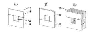
図1(A),(B),(C)は、U字状の副鋼板部材UとI字状の副鋼板部材Iを接合して得られるコア鋼板22,23を積層して形成される従来トランス用コア21の構成を示しており、両副鋼板部材は開口24を閉じるようにして接合縁同士で接合されており、該接合縁は接合方向(図にて上下方向)に対して直角方向に延びている。この接合方向は副鋼板部材Uの脚部の延出方向でもある。
1 (A), (B), and (C) are formed by laminating
図2(A),(B),(C)は本発明によるトランス用コアの構成を示している。 2A, 2B, and 2C show the configuration of the transformer core according to the present invention.
図2(A)は互いに対向して配されて中央に(方形、この場合、正方形)開口26が形成された(外形が方形、この場合、正方形の)コア鋼板25が透磁性材料の第一の対をなす二つの副鋼板部材27,28を有している。一方の副鋼板部材27は開口26の三つの縁部a,b,cを有し、そのうちの上下方向に延びる二つの縁部a,cが互いに対向して位置し、さらに上記副鋼板部材27は、開口26の角部からコア鋼板25の平行な外側縁部35,36へ向け延びる斜接合縁32,33を有している。上記コア鋼板25の他方の副鋼板部材28は、上記開口の第四の縁部dを有していると共に、開口26の第四の縁部dの角部からコア鋼板25の上記外側縁部35,36へ延びる斜接合縁32a,33aを有しており、この斜接合縁32a,33aが上記一方の副鋼板部材27の斜接合縁部32,33と接合して一つのコア鋼板25を形成する。
In FIG. 2A, a
第一の対(副鋼板部材27,28)と同じ形状で、コア鋼板25aを形成する副鋼板部材27a,28aから成る第二の対は、上記第一の対と互いの板面同士が平行な状態で、該第一の対と接面して配置されているが、この第二の対は第一の対に対して、板面に直角な軸線まわりに180°回転した形で配置されている(図2(B)参照)。これに関連して、コア鋼板の板面は、通常、電気絶縁材料がコーティング(塗布)されていてコア鋼板同士が上記コーティングにより絶縁されているということに留意しなければならない。多くの第一の対そして第二の対が、このように交互に配置されていて、二つの「脚部」30,31を有するトランス用コア29を形成する(図2(C)参照)。トランス用コア29の組立後に、該トランス用コア29の一方の脚部31が巻線あるいはコイル(図3における符号32)内を通るように配置される。
The second pair of sub
互いに接合されて一つコア鋼板を形成する一対の副鋼板部材の斜接合縁が斜めになっているために、傾斜角をもった接合縁同士間のギャップを、コア鋼板内の磁力線が横切るようになる。傾斜角をもって磁力線が横切るようにした発想は、接合縁同士間のギャップに対して直角に磁力線が貫通する従来のトランス用コアに比較して、改善を可能とする。最適な傾斜角は、互いに対をなす、コア鋼板積層から成る上下のコア半体が尖端同士が噛み合って正確に接合する鋭角である。しかし、これは、製造そして組立技術上の理由では実用的ではなく、45°前後の角度、もう少し広げると30°〜60°の間の角度が一般的である。このような傾斜角をもった接合による改善は次ごとくである。先ず、U型そしてI型の副鋼板部材が従来のトランス用コアの場合と同様な方法で交互に積層できる。U型からI型副鋼板部材へ磁力線からギャップを横切る位置では、このI型に隣接して接面する副鋼板部材はU型であり、従来のトランス用コアの場合、さらに続く副鋼板部材では、上記位置と同じ位置にギャップを有することがあり、すなわち、トランス用コアの半分だけが局部的に接触状態を得られる。磁力線はギャップに関してはできるだけ狭い部分を経て鋼板部分を通ろうとするので、コア材料で飽和し、それ以上の磁力線は軟鉄を通過できない。残りの磁力線は、高い磁気抵抗をもつギャップを通るようになる。したがって、この遷移(渡り回路)は、トランス用コアの性能を決める重要な要素である。 Since the diagonally joined edges of a pair of sub-steel members that are joined together to form a single core steel plate are slanted, the magnetic field lines in the core steel plate cross the gap between the joined edges having an inclination angle. become. The idea that the magnetic lines of force traverse with an inclination angle can be improved as compared with the conventional transformer core in which the magnetic lines of force penetrate at right angles to the gap between the joining edges. The optimum tilt angle is an acute angle at which the upper and lower core halves made of core steel plate stacks that are paired with each other are joined with each other with the sharp ends meshing with each other. However, this is impractical for manufacturing and assembly engineering reasons, and an angle of around 45 °, an angle between 30 ° and 60 °, more broadly, is common. The improvement by joining with such an inclination angle is as follows. First, U-type and I-type sub-steel members can be alternately laminated in the same manner as in the case of a conventional transformer core. In the position crossing the gap from the line of magnetic force from the U-type to the I-type sub-steel member, the sub-steel member adjacent to the I-type is U-shaped, and in the case of a conventional transformer core, In some cases, there is a gap at the same position as the above position, that is, only half of the transformer core can be locally contacted. Since the magnetic field lines try to pass through the steel plate part through the narrowest possible part with respect to the gap, it is saturated with the core material, and no more magnetic field lines can pass through the soft iron. The remaining magnetic field lines go through a gap with a high magnetic resistance. Therefore, this transition (crossover circuit) is an important factor that determines the performance of the transformer core.
しかしながら、本発明のトランス用コアにおいては、接合縁が図1に示すような脚の延出方向に対して直角となるものでなく、傾斜角をなしている。その結果、コア鋼板積層は、45°の角度をもって、副鋼板部材同士が接合するギャップの領域で従来に比し√2倍の長さをもつので、トランス用コアの効率あるいは性能が向上する。 However, in the transformer core of the present invention, the joining edge is not perpendicular to the extending direction of the leg as shown in FIG. As a result, the core steel sheet lamination has a length of √2 times as long as that of the conventional structure in the gap region where the sub-steel members are joined at an angle of 45 °, so that the efficiency or performance of the transformer core is improved.
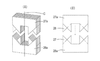
図4(A)は、本発明によるトランス用コアがどのように組み立てられるかを示すための斜視図である。一方では、副鋼板部材27aと28は、図4(A)で示した中心線Cに対して互いに傾斜する斜接合縁部を有し、図2の場合と同様に、交互に積層そして保持されてパックをなし上記コア半体を形成している。他方、図4(A)に見られる副鋼板部材27と28aは、図4(B)の正面図に見られるように、交互に積層そして保持されてパックをなし下部コア半体を形成している。パックをなす上部コア半体と下部コア半体は、図4(B)で矢印の方向に、互いに圧接される。圧接されるときに、副鋼板部材27と28そして副鋼板部材27aと28aは中心線に対して自己センタリングを有する。その結果、最終的に形成されたトランス用コアでは、二種の副鋼板部材をもつ、隣接して接面せるコア鋼板の接合縁は互いに交差する。
FIG. 4A is a perspective view illustrating how the transformer core according to the present invention is assembled. On the other hand, the secondary
コリオリ管における本発明によるトランス用コアの一般的用途が図5に示されてる。 The general use of the transformer core according to the invention in a Coriolis tube is shown in FIG.
コリオリ管33の一部は、この場合、トランス用コア35の中央開口34を貫通している。上記トランス用コアは、本発明による斜接合縁をもつ副鋼板部材で形成されるコア鋼板を積層して作られて、一次巻線を形成する電線のコイル136がトランス用コアの一つの脚部に巻回されており、AC電源に接続されている。該コイル136は二次巻線(図5参照)を形成するコリオリ管133にAC電流を誘導する。ここでコリオリ管133は二つの位置38,39でクランプされたU字状のループ管をなしている。
In this case, a part of the
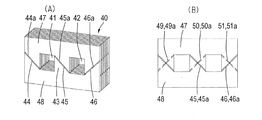
図6(A)は、二つの開口41,42と中央脚部43とを有することにより従来のE−Iコア半体を改良したトランス用コアを示す斜視図であり、図6(B)は正面図である。EI型コア半体をもつトランスでは、多くの場合、一次そして二次巻線の両方がE型コア半体の中央脚部に巻回される。これらの巻線は、しばしば、別の(方形)コイル成形器で巻回される。EそしてIを形成する個々の鋼板部材(副鋼板部材)は、上下に交互に配されてトランス用コアを形成する。横方向にE型をなす図6(A),(B)に示された改善では、三対の斜接合縁44,44a;45,45a;そして46,46aがE型とI型の副鋼板部材に形成されている。これら三対の斜接合縁のうちの二つは、互いに平行である。すなわち、この二つとは、中央脚部43における対45,45aと両側脚部のうちの一方における対44,44aである。完成されたトランス用コアでは、二つの副鋼板部材で形成されるコア鋼板は、図6(B)に見られるように、どの脚部でも斜接合縁が交差している。図6(A)に示されるトランス用コア40は、一般のトランス用コアとしての用途に加え、コリオリ型流量計におけるコリオリ管での電流の誘導のために好適であり、コリオリ管では、例えば、一次巻線がコアの中央脚部43に巻回され、コリオリ管が二つの開口41,42を貫通する閉じた第二ループ(図示せず)を形成する。これは、効率を向上させることに加え、とりわけ、巻線を外して他の巻線に変更する目的のときにコア40が分解容易であるという利点をもたらす。
FIG. 6A is a perspective view showing a transformer core in which the conventional EI core half is improved by having two
図7(A),(B)は、斜接合縁でコア鋼板積層を分割して形成されたコア半体の他の二つの形態を示している。図7(A)は、トランス用コアの開口52の側縁の中央位置から副鋼板部材あるいはコア鋼板積層55の外側縁53,54に向けて延びる斜接合縁での分割によるものであり、結果として、二つの副鋼板部材56,57を形成している。図7(B)は、コアの開口58の隅部から副鋼板部材あるいはコア鋼板積層の両方の隅部へ延びる斜接合縁での分割によるものであり、結果として、U字状の副鋼板部材60とI字状の副鋼板部材61を形成している。
FIGS. 7A and 7B show two other forms of the core half formed by dividing the core steel plate stack at the oblique joining edges. FIG. 7A is a result of the division at the oblique joint edge extending from the center position of the side edge of the
図8は、実質的に閉ループをなす(一まわりをなす)流路を形成するようにU字状に屈曲されたコリオリ型ループ検出管2による流量計の特殊な形態(本発明はこれに限定されない)を示している。ループ状検出管2は、二つの平行な側管部2c,2dを有し、これらは一端側で第一連絡管部2eそして他端で二つの第二連絡管部2a,2bで接続されている。二つの第二連絡管部2a,2bは、これらが側管部2c,2dに接続されている側とは反対側で、流れ媒体のための可撓流入管3と可撓流出管4に接続されている。好ましくは、ループ状検出管2と流入管3そして流出管4は一つの連続した管の部分をなしている。ループ状検出管2は、全体として、丸みをもつ隅部をもった矩形状をなし、曲げ成形し易い形状になっている。流入管3は、供給/排出ブロックを経て、供給ライン6に接続され、流出管4は排出ライン7に接続されている。この形態の流入管3と流出管4は、ループ状検出管2のループ内にあって、取付手段12によってフレーム13に取り付けられている。可撓流入管3と流出管4は検出管2のループの一部を形成していないが、フレーム13へのループ状検出管2の可撓性をもった取付に供している。こうして、ループ状検出管2は、流入管と流出管によって可撓性をもって懸吊されているとみなすことができる。ループ状検出管2と流入管3そして流出管4は、一つの管材で作られていることが好ましい。これは、例えば、ステンレス鋼管で外径が約0.7mmそして壁厚が約0.1mmとして形成できる。検出管2のループの大きさと管が耐えられる圧力(例えば、100bar)にもよるが、管の外径は、通常、1mmより小さく、壁厚は0.2mmあるいはそれ以下である。
FIG. 8 shows a special form of a flow meter with a Coriolis type
流入管3と流出管4はループ状検出管2の対称主軸線(鉛直方向に延び流入管3と流出管4の間を通る線)に関して対称でこの対称主軸線に近接して両側に延びており、取付手段12、例えばクランピング、鑞接、溶接によって取り付けられている。この取付手段12はフレーム13に取り付けられている。流入管3と流出管4は直接フレーム13に取り付けられていてもよい。
The inflow pipe 3 and the
図8の構造において、対称主軸線(回転の主軸あるいは励起軸線となる)まわりにループ状の検出管2を回転させるための励磁手段は、二箇所で空隙9,10が形成され、フレーム13に固定されたマグネットヨーク8を有し、該マグネットヨーク8は永久磁石19が設けられており、ループ状の検出管2(上記第二連絡管部)の部分2a,2bが上記空隙を通るように延びており、検出管2内へ電流をもたらす手段を有している。これらは、図8における誘導手段によって検出管2内へ電流を生じせしめるための手段である。永久磁石マグネットヨーク8は二つの上ヨーク部8aと8a’とを有し、これらは空隙9,10によって下ヨーク部8bから分離されている。ヨーク部8aと8a’の間には永久磁石19が配設されており、その一方の極(N極)はヨーク部8aに向いており、他方の極(S極)はヨーク部8a’の方に向いている。
In the structure of FIG. 8, the exciting means for rotating the loop-shaped
二つのトランス用コア17,17aがそれぞれコイル18a,18bを有し、これらのトランス用コアが側管部2c,2dを通っていて、これらのトランス用コアによって、検出管内に電流が生ずる。コイルは図示のごとくトランス用コアの内側の脚部に巻かれていても、あるいは他の側に巻かれていてもよい。永久磁石ヨーク8の空隙9,10のそれぞれに電流の方向を横切り互いに反対に向く磁界が生ずるが、この磁界と検出管2内に生ずる(交番)電流との組み合わせが検出管にトルクをもたらし、対称主軸線まわりの振動あるいは回転(捩りモード)を始める。
The two
流れ媒体が検出管内を流れると、検出管は、コリオリ力の影響のもとで、対称主軸線を横切る応答軸線に関して振動(揺動モード)を始める。作動中、流れ媒体の様子を表わす連絡管部2eの点における正弦波変位が、連絡管部2eに近接して配された第一センサ11aそして第二センサ11bを有するコリオリ効果センサによって検知される。第一そして第二センサは、対称主軸線と連絡管部2eとの交点近くで該対称主軸線の両側に対称的に配置されている。第三センサ11cが修正の目的に配されていてもよい。センサは、例えば、電磁型、誘導型、容量型あるいは超音波型とすることができる。しかし、図8の形態の場合、光学センサが用いられている。ここで用いられている光学センサは、いわゆるオプトセンサ11a,11bそして11cであり、それぞれフレーム13に取り付けられたU字型ハウジングを有し、光源(例えばLED)がU字の一方の脚部に配置され、感光セル(例えば、フォトトランジスタ)が他方の脚部で上記光源に対向して配置されている。連絡管部2eあるいは、これに取り付けられた羽根はU字状センサハウジングの脚部におけるセンサ11aと11bの間そして、もし存在すればセンサ11Cとの間を移動可能となっていて、光源からの光を多かれ少なかれ遮断できる。
When the flow medium flows in the detection tube, the detection tube starts to vibrate (oscillation mode) with respect to the response axis crossing the symmetric main axis under the influence of the Coriolis force. In operation, a sinusoidal displacement at the point of the connecting
図1から図7までのすべては、コア鋼板積層が接合される方向に平行で開口を通る中心線に対して副鋼板部材が対称な形態を示した。自己センタリング効果を確保しつつ磁束の誘導を行える大きな有効斜接合縁長を得る同様の効果は、上記対称性を有しない形態においても達成できる。図9から図11はこの例を示す。 All of FIG. 1 to FIG. 7 showed a form in which the secondary steel plate member was symmetric with respect to the center line passing through the opening parallel to the direction in which the core steel plate lamination was joined. The same effect of obtaining a large effective oblique joint edge length capable of guiding the magnetic flux while ensuring the self-centering effect can be achieved even in the form having no symmetry. 9 to 11 show this example.
図9(A)は、斜接合縁が副鋼板部材の両方の脚部で同じ方向、すなわち平行となっている形態を示す。図示の例では、同一形状の副鋼板部材62aと62bの斜接合縁p,qが平行である。この場合の利点は、一つの種類の形状の副鋼板部材でトランス用コアを完全に構成できるということである。副鋼板部材62aと62bとで矩形(正方形)開口をもった矩形(正方形)コア鋼板を形成する。副鋼板部材62a,62bを対として接合すると、この対に対して180°回転した状態の副鋼板部材63a,63bの対のコア鋼板と同一のものが得られる。
FIG. 9 (A) shows a form in which the oblique joining edges are in the same direction, that is, in parallel, in both legs of the secondary steel plate member. In the illustrated example, the oblique joint edges p and q of the
図9(B)は、副鋼板部材62a等を交互に積層して接合後に得られる、本発明による矩形(正方形)トランス用コア63を形成する、二つのコア鋼板積層(コア半体)を示している。
FIG. 9B shows two core steel plate laminates (core half bodies) forming a rectangular (square)
図10(A)は、同一形状のL型副鋼板部材64a,64bの対を用いた例を示しており、これらの副鋼板部材の斜接合縁p’,q’は一つの直線上に位置している。同一形状の副鋼板部材65a,65bの対は、上記対副鋼板部材の対64a,64bを90°回転することにより得られ、互いに上記斜接合縁にて接合される。この実施形態では、前出の実施形態の場合よりも、実質的クランプ長が大きい。
FIG. 10A shows an example using a pair of L-shaped secondary
図10(B)は、図9(B)と同様に交互に配置された副鋼板部材64a等の二つの積層を示し、これらの副鋼板部材は、互いに接合された後に、本発明にしたがい、矩形(方形)のトランス用コア66を形成する。L型の副鋼板部材が正方形でなく長方形を形成するときには、斜接合縁同士は平行となる。
FIG. 10 (B) shows two stacks of
図11(A)は、互いに接合する斜接合縁p”,q”をもつ二つの副鋼板部材67a,67bを用いた例を示している。既述の実施形態とは異なり、この実施形態では、形成されるコア鋼板の中心線に対して副鋼板部材は対称とはなっていない。副鋼板部材67a,67bは、それらの斜接合縁の延長線が、形成されるコア鋼板の中心線上で交わっていないので、互いに同一な形状とはなっていない。換言すれば、それぞれの斜接合縁が開口の縁部と同じレベルでは交差していない。図11(A)の形態は、副鋼板部材の斜接合縁(分割縁)の位置と角度の可能性を単に示しただけである。異なる位置で分割される斜接合縁をもって、コア鋼板を形成するさらに異なる形状のものを用いることも可能である。これによって、斜接合縁長をさらに大きくすることができる。
FIG. 11A shows an example in which two sub
図11(B)は、互いに接合されて本発明の矩形(方形)トランス用コアを形成するように交互に配された副鋼板部材67a等の二つの積層であって、図9(B)そして図10(B)と類似しているものを示している。
FIG. 11B shows two stacks of
既出の図に示されたコア鋼板は、すべて、矩形もしくは正方形であった。しかし、本発明の原理とするところは、他のすべてのコア鋼板に同じく適用でき、形に制限はなく、例えば、円形、楕円形、菱形、不等辺四角形、台形、そして閉じた形状のものすべてに適用できる。好ましくは、これらの形態すべてにおいて一定した同じ大きさの(矩形の)開口を有していることである。 All of the core steel plates shown in the above figures were rectangular or square. However, the principle of the present invention can be applied to all other core steel plates as well, and there is no limitation on the shape, for example, all round, oval, rhombus, unequal square, trapezoid, and closed shapes. Applicable to. Preferably, all of these forms have a constant (rectangular) opening of the same size.
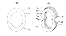
これに関連して、図12(A)は楕円の開口そして外形を有する楕円のコア鋼板70の正面図を示しており、ここでコア鋼板70は、斜接合縁71a,72aと71b,72b(図12(B)を参照)によって互いに接合される二つの副鋼板部材71,72を有している。これと同一形状の副鋼板部材を180°回転して得られる二つの副鋼板部材73,74は接合されてコア鋼板70を形成しており、斜接合縁は破線(図12(A)参照)で示されている。この実施形態では、隣接して接面するコア鋼板同士が互いに補完する斜接合縁は(コア鋼板の面内では)互いに交差していない。
In this regard, FIG. 12 (A) shows a front view of an elliptical
この斜接合縁の形態は、他の形のコア鋼板、例えば、矩形、正方形、円形等にも適用可能である。このことは、以下の図示の例についても言えることである。 This form of the oblique joining edge can be applied to other shapes of core steel plates, for example, a rectangle, a square, a circle, and the like. This is also true for the example shown below.
図13(A)は、斜めに分割された副鋼板部材76,77から成る不等辺四角形のコア鋼板75の正面図であり、図13(B)はかかるコア鋼板75をもつトランス用コアの組立を示す斜視図である。このような不等辺四角形をなしている理由で、隣接して接面する副鋼板部材は、互いに補完し合う斜接合縁が異なる面にある第一そして第二の形式のものとなる。
FIG. 13A is a front view of a non-equal-sided square
図14(A)は、閉じた不規則な形状のコア鋼板を形成する二つの副鋼板部材から成る該コア鋼板の正面図を示している。 FIG. 14 (A) shows a front view of the core steel plate composed of two sub steel plates forming a closed irregularly shaped core steel plate.
図14(B)はこのようなコア鋼板から成るトランス用コアの組立体を示している。この場合、隣接して接面する副鋼板部材同士の斜接合縁は互いに交差している(図14(A)参照)。 FIG. 14B shows an assembly of a transformer core made of such a core steel plate. In this case, the oblique joining edges of the sub-steel members adjacently contacting each other intersect each other (see FIG. 14A).
結言として、本発明は、透磁性材料の平坦なコア鋼板を多数積層してトランス用コアを形成し、各コア鋼板が第一そして第二の副鋼板部材で少なくとも一つの開口を形成している上記トランス用コアに係る。副鋼板部材は、開口の両側に位置してコア鋼板の中心線に対して傾斜する斜接合縁で互いに接合される。本発明は、また、コリオリ管が上記開口を貫通していて該コリオリ管に電流を誘導するコリオリ型流量計に用いられるトランス用コアにも関している。 In conclusion, the present invention forms a transformer core by laminating a large number of flat core steel plates made of a magnetically permeable material, and each core steel plate forms at least one opening with first and second sub-steel members. It relates to the transformer core. The secondary steel plate members are joined to each other at oblique joint edges that are located on both sides of the opening and are inclined with respect to the center line of the core steel plate. The present invention also relates to a transformer core used in a Coriolis flow meter in which a Coriolis tube passes through the opening and induces a current in the Coriolis tube.
さらには、特に、コア鋼板を交互に積層して得られるトランス用コアの各コア鋼板は斜接合縁をU字状の脚部に有し、隣接して接面せるコア鋼板同士は上記斜接合縁が逆向になるように配される。 Furthermore, in particular, each core steel plate of the transformer core obtained by alternately laminating the core steel plates has a slanted joint edge at the U-shaped leg portion, and the core steel plates that are adjacently contacted with each other are obliquely joined. Arranged so that the edges are reversed.
21 トランス用コア
22 コア鋼板
23 コア鋼板
24 開口
25,25a コア鋼板
26 開口
27,27a 副鋼板部材
28,28a 副鋼板部材
29 トランス用コア
30 脚部
31 脚部
32,32a (斜)接合縁
33,33a (斜)接合縁
35 (外側)縁部
36 (外側)縁部
40 トランス用コア
41 開口
42 開口
43 中央脚部
44,44a (斜)接合縁
45,45a (斜)接合縁
46,46a (斜)接合縁
52 開口
53 (外側)縁部
54 (外側)縁部
55 コア鋼板積層
56 副鋼板部材
57 副鋼板部材
58 開口
60 副鋼板部材
61 副鋼板部材
62a,62b 副鋼板部材
63a,63b 副鋼板部材
63 トランス用コア
64a,64b 副鋼板部材
65a,65b 副鋼板部材
66 トランス用コア
67,67a 副鋼板部材
70 コア鋼板
71a,71b (斜)接合縁
72a,72b (斜)接合縁
75 コア鋼板
76 副鋼板部材
77 副鋼板部材
C 中心線
p’,q’ (斜)接合縁
p”,q” (斜)接合縁
21 Transformer core
22 core steel plate
23 core steel plate
24 opening
25, 25a Core steel plate
26 Opening
27, 27a Sub-steel member
28, 28a Sub-steel member
29 Transformer core
30
32, 32a (oblique) joint edge
33, 33a (oblique) joint edge
35 (outside) edge
36 (Outside) edge
40 transformer core
41
43 Central leg
44, 44a (oblique) joint edge
45, 45a (oblique)
63a,
65a,
70
C Center line p ', q' (oblique) joint edge p ", q" (oblique) joint edge
Claims (17)
各コア鋼板の副鋼板部材が、開口の両側にてコア鋼板の中心線に対して傾斜せる第一そして第二接合縁同士で接合されていることを特徴とするトランス用コア。 In a transformer core having a plurality of core steel plates each made of a magnetically permeable material and having a flat plate surface, each core steel plate having first and second auxiliary steel plate members so as to form at least one opening. ,
A transformer core, wherein sub-steel members of each core steel plate are joined at first and second joining edges that are inclined with respect to the center line of the core steel plate on both sides of the opening.
Applications Claiming Priority (1)
| Application Number | Priority Date | Filing Date | Title |
|---|---|---|---|
| NL1033887A NL1033887C2 (en) | 2007-05-24 | 2007-05-24 | Transformer core. |
Publications (2)
| Publication Number | Publication Date |
|---|---|
| JP2008294435A true JP2008294435A (en) | 2008-12-04 |
| JP2008294435A5 JP2008294435A5 (en) | 2011-01-13 |
Family
ID=38810328
Family Applications (1)
| Application Number | Title | Priority Date | Filing Date |
|---|---|---|---|
| JP2008118139A Pending JP2008294435A (en) | 2007-05-24 | 2008-04-30 | Transformer core and coriolis flowmeter having the same |
Country Status (4)
| Country | Link |
|---|---|
| US (1) | US7843306B2 (en) |
| EP (1) | EP1995742B1 (en) |
| JP (1) | JP2008294435A (en) |
| NL (1) | NL1033887C2 (en) |
Cited By (4)
| Publication number | Priority date | Publication date | Assignee | Title |
|---|---|---|---|---|
| JP2013130470A (en) * | 2011-12-21 | 2013-07-04 | Tamura Seisakusho Co Ltd | Loop core for current sensor and current sensor |
| JP2019009277A (en) * | 2017-06-23 | 2019-01-17 | 株式会社タムラ製作所 | Core, core laminate, and stationary induction apparatus |
| JP2021150611A (en) * | 2020-03-23 | 2021-09-27 | 東芝産業機器システム株式会社 | Cut core |
| JP7529005B2 (en) | 2021-12-22 | 2024-08-06 | Jfeスチール株式会社 | Stacked core and method of manufacturing stacked core |
Families Citing this family (6)
| Publication number | Priority date | Publication date | Assignee | Title |
|---|---|---|---|---|
| JP5192531B2 (en) * | 2010-10-29 | 2013-05-08 | 三菱電機株式会社 | Ignition coil for internal combustion engine |
| DE102011107252A1 (en) * | 2011-07-14 | 2013-01-17 | Schneider Electric Sachsenwerk Gmbh | Coil for current limitation |
| US9631962B2 (en) * | 2014-03-18 | 2017-04-25 | Rosemount Inc. | Magnetic core configuration for magnetic flowmeters having a plurality of layers of magnetically permeable material |
| CN104008862A (en) * | 2014-05-30 | 2014-08-27 | 昆山佑翔电子科技有限公司 | Transformer core |
| CN105742031B (en) * | 2014-12-10 | 2017-11-21 | 辽宁易德实业集团有限公司 | The stacked iron core and its process of a kind of solid transformer |
| CN105469951A (en) * | 2016-02-10 | 2016-04-06 | 齐侠 | Folding type planar one-phase open transformer core |
Citations (5)
| Publication number | Priority date | Publication date | Assignee | Title |
|---|---|---|---|---|
| JPS4828008U (en) * | 1971-08-09 | 1973-04-05 | ||
| JPS5044614U (en) * | 1973-08-27 | 1975-05-06 | ||
| JPS549854U (en) * | 1977-06-24 | 1979-01-23 | ||
| JPS5799718A (en) * | 1980-12-12 | 1982-06-21 | Fujitsu Ltd | Assembling method for coil with magnetic core |
| JP2005150507A (en) * | 2003-11-18 | 2005-06-09 | Toshiba Corp | Wound iron core and transformer |
Family Cites Families (11)
| Publication number | Priority date | Publication date | Assignee | Title |
|---|---|---|---|---|
| DE7342490U (en) * | 1974-05-16 | Licentia Gmbh | Magnetic core composed of sheet metal | |
| US2467867A (en) * | 1944-09-11 | 1949-04-19 | Gen Electric | Electromagnetic induction apparatus and method of forming same |
| GB680677A (en) | 1949-10-27 | 1952-10-08 | Comb Eng Superheater Inc | Water supply system for forced recirculation steam generator |
| GB680577A (en) * | 1950-03-30 | 1952-10-08 | N G N Electrical Ltd | Improvements in laminated magnetic cores for electric transformers |
| US2942218A (en) * | 1952-08-08 | 1960-06-21 | Mc Graw Edison Co | Core for electromagnetic induction apparatus |
| US3513423A (en) * | 1969-01-08 | 1970-05-19 | Mc Graw Edison Co | Three-phase magnetic core |
| US3918153A (en) * | 1971-03-22 | 1975-11-11 | Westinghouse Electric Corp | Method of constructing a magnetic core |
| US4520556A (en) * | 1981-05-04 | 1985-06-04 | General Electric Company | Methods for assembling a transformer core |
| DE4410160C1 (en) * | 1994-03-24 | 1995-10-05 | Ulrich Dipl Ing Elsen | Heat-resistant drive and measuring coil for oscillation pipe mass flowmeter |
| US5777537A (en) * | 1996-05-08 | 1998-07-07 | Espey Mfg. & Electronics Corp. | Quiet magnetic structures such as power transformers and reactors |
| US7057489B2 (en) * | 1997-08-21 | 2006-06-06 | Metglas, Inc. | Segmented transformer core |
-
2007
- 2007-05-24 NL NL1033887A patent/NL1033887C2/en not_active IP Right Cessation
-
2008
- 2008-03-21 EP EP08075203.3A patent/EP1995742B1/en active Active
- 2008-04-30 JP JP2008118139A patent/JP2008294435A/en active Pending
- 2008-05-08 US US12/117,050 patent/US7843306B2/en active Active
Patent Citations (5)
| Publication number | Priority date | Publication date | Assignee | Title |
|---|---|---|---|---|
| JPS4828008U (en) * | 1971-08-09 | 1973-04-05 | ||
| JPS5044614U (en) * | 1973-08-27 | 1975-05-06 | ||
| JPS549854U (en) * | 1977-06-24 | 1979-01-23 | ||
| JPS5799718A (en) * | 1980-12-12 | 1982-06-21 | Fujitsu Ltd | Assembling method for coil with magnetic core |
| JP2005150507A (en) * | 2003-11-18 | 2005-06-09 | Toshiba Corp | Wound iron core and transformer |
Cited By (5)
| Publication number | Priority date | Publication date | Assignee | Title |
|---|---|---|---|---|
| JP2013130470A (en) * | 2011-12-21 | 2013-07-04 | Tamura Seisakusho Co Ltd | Loop core for current sensor and current sensor |
| JP2019009277A (en) * | 2017-06-23 | 2019-01-17 | 株式会社タムラ製作所 | Core, core laminate, and stationary induction apparatus |
| JP2021150611A (en) * | 2020-03-23 | 2021-09-27 | 東芝産業機器システム株式会社 | Cut core |
| JP7402092B2 (en) | 2020-03-23 | 2023-12-20 | 東芝産業機器システム株式会社 | cut core |
| JP7529005B2 (en) | 2021-12-22 | 2024-08-06 | Jfeスチール株式会社 | Stacked core and method of manufacturing stacked core |
Also Published As
| Publication number | Publication date |
|---|---|
| US20080290982A1 (en) | 2008-11-27 |
| EP1995742A3 (en) | 2009-02-25 |
| US7843306B2 (en) | 2010-11-30 |
| EP1995742B1 (en) | 2017-08-23 |
| EP1995742A2 (en) | 2008-11-26 |
| NL1033887C2 (en) | 2008-11-25 |
Similar Documents
| Publication | Publication Date | Title |
|---|---|---|
| JP2008294435A (en) | Transformer core and coriolis flowmeter having the same | |
| US3878495A (en) | Magnetic core for electrical inductive apparatus | |
| EP0744757A1 (en) | D.c. reactor | |
| WO1999026451A1 (en) | Thin electromagnetic transducer | |
| JPWO2012105261A1 (en) | Motor stator and motor | |
| JP2011043422A (en) | Current sensor, and method of manufacturing the same | |
| JP2015142095A (en) | Stationary induction apparatus and method for manufacturing the same | |
| JP2000083364A (en) | Movable core linear motor | |
| WO2019013131A1 (en) | Planar transformer and dcdc converter | |
| JP4555838B2 (en) | Induction heating device | |
| JP2006332235A (en) | Winding iron core | |
| JP4001505B2 (en) | DC reactor | |
| JP2006041002A (en) | Ferrite core and transformer using the same | |
| JP2013069826A (en) | Reactor | |
| JP6926787B2 (en) | Iron core structure, transformer, and iron loss suppression method | |
| RU2007139257A (en) | FLUID INDUCTION HEATER | |
| KR101904100B1 (en) | Core for transformer | |
| JP2018186113A (en) | Stationary induction apparatus | |
| JP2010192742A (en) | Reactor | |
| KR200203543Y1 (en) | Reactor structure with air gap on magnetic pass | |
| JP2009246080A (en) | Stationary induction machine | |
| JP2004047910A (en) | Reactor | |
| JP2008258291A (en) | Ignition coil for internal combustion engine, and manufacturing method thereof | |
| JP6917676B2 (en) | Linear motor system | |
| TWI396209B (en) | Transformers and circuit devices for controlling transformers |
Legal Events
| Date | Code | Title | Description |
|---|---|---|---|
| A521 | Written amendment |
Free format text: JAPANESE INTERMEDIATE CODE: A523 Effective date: 20101122 |
|
| A621 | Written request for application examination |
Free format text: JAPANESE INTERMEDIATE CODE: A621 Effective date: 20101122 |
|
| A977 | Report on retrieval |
Free format text: JAPANESE INTERMEDIATE CODE: A971007 Effective date: 20121011 |
|
| A131 | Notification of reasons for refusal |
Free format text: JAPANESE INTERMEDIATE CODE: A131 Effective date: 20121018 |
|
| A02 | Decision of refusal |
Free format text: JAPANESE INTERMEDIATE CODE: A02 Effective date: 20130328 |
