JP2008291902A - Oil tank freely changing assembling direction and linear slide for installing oil tank - Google Patents
Oil tank freely changing assembling direction and linear slide for installing oil tank Download PDFInfo
- Publication number
- JP2008291902A JP2008291902A JP2007137231A JP2007137231A JP2008291902A JP 2008291902 A JP2008291902 A JP 2008291902A JP 2007137231 A JP2007137231 A JP 2007137231A JP 2007137231 A JP2007137231 A JP 2007137231A JP 2008291902 A JP2008291902 A JP 2008291902A
- Authority
- JP
- Japan
- Prior art keywords
- oil tank
- oil
- tool
- feeding tool
- tank
- Prior art date
- Legal status (The legal status is an assumption and is not a legal conclusion. Google has not performed a legal analysis and makes no representation as to the accuracy of the status listed.)
- Granted
Links
Images


Landscapes
- Bearings For Parts Moving Linearly (AREA)
- Rolling Contact Bearings (AREA)
Abstract
Description
本発明は、組付方向変換自在なオイルタンク及びオイルタンクのリニアスライドを提供する。リニアスライドのオイルタンクを組み付ける際して周辺の状況に応じてその方向を任意に変換することを主な用途とする。またオイルタンクの内部の周りにいずれも毛細原理により液体を吸収または輸送する送油具を敷設すると共に、該送油具に対応するオイルタンク上に一つないし複数の微細孔を設け、微細孔を設置することでオイルタンクの内部が常時に正圧に保たれ、さらに、潤滑油(脂)自身の表面張力により微細孔から流出することはない。また、オイルタンクの方向変換の組付ける時、オイルタンク内の潤滑油(脂)が下方向へ集中して流動する特性を利用して、周りに分布している送油具のいずれも潤滑油(脂)と接触して毛細原理により潤滑油(脂)をスライドのボール溝に正常に輸送することによって、ボール溝上に回転するボールが順調に潤滑することができる。 The present invention provides an oil tank and a linear slide of the oil tank that are freely changeable in assembly direction. When assembling the oil tank of the linear slide, the main application is to arbitrarily change the direction according to the surrounding situation. In addition, an oil supply device that absorbs or transports liquid by the capillary principle is laid around the inside of the oil tank, and one or more fine holes are provided on the oil tank corresponding to the oil supply device. By installing the oil tank, the inside of the oil tank is always kept at a positive pressure, and further, it does not flow out of the fine holes due to the surface tension of the lubricating oil (grease) itself. Also, when assembling the direction change of the oil tank, the lubricant oil (grease) in the oil tank concentrates and flows downward, so that any of the oil feeding tools distributed around The ball rotating on the ball groove can be smoothly lubricated by normally transporting the lubricating oil (grease) to the ball groove of the slide by contact with the (grease) and the capillary principle.
米国特許第6290394号(以下、第1の先願と略称する)を示した図2及び図7を参照するように、エンドカバー6の側辺にオイルタンク21を組み付け、該オイルタンク21がスライド2に合わせて冂字状形状に設けられる。その底部の溝孔は、スライド2の往復変移を提供でき、かつ該溝孔の両対向した内側面にはそれぞれ突出した塗布具30が設けられる。両塗布具30はオイルタンク21の内部まで連通してオイルタンク21内の潤滑油を吸収するとともに、潤滑油を塗布具30の表面40に輸送することができる。前記各塗布具30の表面は、常時にスライド2の両側のボール溝4に接触して該両ボール溝4内に回転するボール(ボールがスライダ1と両エンドカバー6中に循環還流する。図示せず)が良い潤滑が得られる。しかし、この第1の先願は、以下の欠点を有している。
As shown in FIGS. 2 and 7 showing US Pat. No. 6,290,394 (hereinafter referred to as the first prior application), an
1.該第1の先願の塗布具30は、オイルタンク21のの内底部からある距離を有しているので、オイルタンク21内のオイルレベルが塗布具30より低くなった場合、該塗布具30は、潤滑油を吸引できなくなり、作業員が即時に発見できなければ、スライド2、ボール及びスライダ1を磨耗させ、ひいて機具の精度まで影響することになる。
1. Since the
2.前記第1の先願のオイルタンク21を組み付ける際、一方向のみ組み付けることは可能である。即ち、塗布具30は、常時に下方に位置して始めて潤滑油を吸収することができるため、特殊な場合、オイルタンク21を転倒させ、横転させなければ、この先願を使用することができない。
2. When assembling the
さらに、台湾出願の第93128789号の「自己潤滑ユニットを備えたリニアスライド」(以下、第2の先願と略称)を参照するように、該第2の先願は、本願の発明者の先願で、前記第1の先願の欠点を既に克服している。しかし、特殊な作業環境においては、自己潤滑ユニットを転倒したり横転したりして組み付けなければならない場合、オイルボックス51の通油孔515がエンドカバー30の通油孔31に整列できなくなるため、潤滑油は、オイルボックス51の通油孔515から流出して、潤滑油の無駄になる。もしくは、該通油孔515を密封させると、その他の問題が生じられ、即ち、潤滑油が消耗されつつ、オイルレベルが下げた場合、オイルボックス51の内部は負圧になり、送油素子53の毛細原理による潤滑油の送油効率が低くなるため、スライド20の各回転溝21の潤滑効果が悪く、スライド21、ボール及びスライド10を磨耗して機具の精度まで影響することになる。
前記の従来のリニアスライドのオイルタンクの欠点に鑑み、本発明者は、この製品に関わる長年の研究開発の経験を生かし、研究を研究に積み重ねて設計改良つつ、さらにサンプルを試作して実験を繰り返した上で、改良を加えて漸く下記の発明の目的として達成し得る本発明を案出することができた。 In light of the shortcomings of the oil tank of the conventional linear slide described above, the present inventor has made use of his many years of research and development experience related to this product, accumulated research into research and improved design, and further prototyped samples and conducted experiments. After repeating the invention, the present invention that can be achieved as the object of the following invention can be devised with improvement.
即ち、本発明は、主に、オイルタンク内部の周りの何れも送油具が敷設されると共に、該送油具に対応するオイルタンク上にオイルタンクの外部と通気可能な通気孔を設けることによって、オイルタンク内の圧力と外部の圧力をバランスに保たれ、オイルタンクの組付方向が任意に変換されても、送油具によりオイルタンク内の潤滑油(脂)をリニアスライドのボール溝に正常に輸送させ、リニアスライドの潤滑に提供できる目的とする。 That is, according to the present invention, oil supply tools are mainly laid around the inside of the oil tank, and a vent hole that allows ventilation to the outside of the oil tank is provided on the oil tank corresponding to the oil supply tool. This keeps the pressure inside the oil tank and the external pressure in balance, and even if the assembly direction of the oil tank is changed arbitrarily, the lubricating oil (grease) in the oil tank is fed by the oil feeder to the ball groove of the linear slide. The purpose is to provide normal lubrication for linear slides.
前記の発明の目的を達成するため、本発明の改良特徴として、オイルタンクの内部は、潤滑油(脂)の蓄積可能な収容空間を備え、該オイルタンクの周りに互い連結した送油具が敷設される。該送油具は毛細原理により潤滑油(脂)をオイルタンクの外部まで送出し、該オイルタンクは組付部を有し、オイルタンクの組付部がオイルタンクの内部まで突出する凸管で、かつ該凸管の突出端が閉鎖端として設置され、該凸管にオイルタンクの外部まで連通する通孔を有し、該凸管の外リングは一部下方向へ凹んだ段階状の欠口が切断される。欠口の両側は、さらに前記凸管の通孔を連通するための細い溝が開設され、該凸管の欠口は、送油具を承接するのに用いられ、前記両細い溝の軸方向が送油具に被覆され、該両細い溝の径方向が凸管の通孔とオイルタンクの内部とに連通する。前記オイルタンクの組付部は、内部に送油具を備えた連結具との結合を提供することができ、該連結具は、さらにエンドカバーの側面に固定された固定台とを結合する。該固定台に塗布シートを設け、該塗布シートがスライドに対応する複数のボール溝は、それぞれ突出部を形成してボール溝と常時接触に保たれる。潤滑油(脂)は、オイルタンク中の送油具から連結具の送油具まで送油し、さらに、連結具の送油具から固定台の塗布シートまで送油させ、該塗布シートの両突出部により潤滑油(脂)をスライドの両側の複数のボール溝に塗布することができる。 In order to achieve the object of the present invention, as an improved feature of the present invention, the interior of the oil tank has a storage space in which lubricating oil (grease) can be accumulated, and an oil feeding tool connected to each other around the oil tank is provided. Laid. The oil feeding device sends lubricating oil (grease) to the outside of the oil tank by the capillary principle, the oil tank has an assembly part, and the assembly part of the oil tank is a convex tube protruding to the inside of the oil tank. And the protruding end of the convex tube is provided as a closed end, and has a through hole communicating with the convex tube to the outside of the oil tank, and the outer ring of the convex tube is partially stepped in a downward direction. Is disconnected. On both sides of the notch, a narrow groove is further provided for communicating the through hole of the convex tube, and the notch of the convex tube is used to contact the oil feeding tool. Is covered with the oil feeding tool, and the radial direction of the two narrow grooves communicates with the through hole of the convex tube and the inside of the oil tank. The assembly part of the oil tank can provide a coupling with a coupling tool having an oil feeding tool therein, and the coupling tool further couples a fixing base fixed to the side surface of the end cover. A coating sheet is provided on the fixed base, and the plurality of ball grooves corresponding to the sliding of the coating sheet form protrusions and are always kept in contact with the ball grooves. Lubricating oil (grease) is fed from the oil feeding tool in the oil tank to the oil feeding tool of the coupling tool, and is further fed from the oil feeding tool of the coupling tool to the application sheet of the fixing base. Lubricating oil (grease) can be applied to the plurality of ball grooves on both sides of the slide by the protrusions.
審査官及び当該技術分野に熟知している者が本発明に対し、より一層理解するためには、より具体的な実施例を挙げて、下記のように詳しく説明する。(ただし、当該実施例は、単に便利に説明するために用いられるもので、本発明による日後の実施など、これに限るものでなく、本発明の技術特徴により成された何れの改良実施など本発明に拘束されるべきとする)。 In order for the examiner and those familiar with the technical field to understand the present invention more fully, a more specific example will be given and explained in detail as follows. (However, this embodiment is merely used for convenient explanation, and is not limited to the implementation of the present invention, such as implementation after the day. The present invention includes any improvements implemented by the technical features of the present invention. Should be bound by the invention).
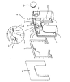
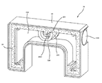
図1ないし図3を参照するように、本実施例のオイルタンク20は、開放端をなした本体23に送油具22を設け、該本体23の開放端は、さらに閉鎖板21で密閉して良い密封効果を有する中空本体にならしめる。該本体23の内部は、潤滑油(脂)を蓄積する収容空間234を形成し、該本体23が開放端に隣接した全内壁面に閉鎖板21の寄りかかるための凹んだ階段状縁231を形成する。本体23の内部空間234の周りの隅部は、それぞれ欠口233を備えた支持柱232をさらに設置し、各支持柱232が本体23の閉鎖端から開放端に延伸する。前記欠口233のいずれも本体23の内壁面に対向して設けられ、該本体23の閉鎖端にさらに開放端に延伸する、通孔236を備えた凸管235が設置され、該凸管235の通孔236は、本体23の内外に連通する。該凸管235は、密封状態になるように閉鎖板21に当接して収容空間234中の潤滑油(脂)が凸管235の通孔236に流入することなく、また、該凸管235の外リングは、一部の凹部を切断した段階状の欠口で、かつ該欠口237の両側には、さらに軸方向へ凹んだ細い溝238をそれぞれ設け、前記凸管235の通孔236と連通する。該細い溝238の大きさは、極めて小さく潤滑油(脂)の表面張力の作用により、潤滑油(脂)の浸出がないようになる。前記凸管235の欠口237と周りの複数の支持柱232の欠口233により送油具22を承接するための部位が構成され、この両細い溝238の軸方向は、送油具22に被覆され、両細い溝238の径方向が前記凸管235の通孔236と本体23の内部の収容空間234とに連通し、該凸管235の通孔236の内壁面に突起のリンク状凸縁2351を形成する。前記本体23のいずれか一側面に内部の収容空間234と連通する注油孔239が開設され、オイルタンク20内の潤滑油(脂)が使い終わった際に、該注油孔239から潤滑油(脂)を注入することができる。該注油孔239がゴム製のゴムプラグ230で封じられ極めて良い水密性が実現でき、潤滑油(脂)の浸出問題が解除できる。前記送油具22は、毛細原理により液体を吸収し伝送可能な材質、例えば、フォームプラスチック、ウールフェルトからなり、該送油具22が長条状に延出され前記本体23の収容空間234の左右、上下、前後の位置に分布される。該送油具22は、前記各複数の支持柱232の欠口233及び前記凸管235の欠口237に承接するように設けられると同時に、前記閉鎖板21の僅かな押圧により定位され、該送油具22が本体23の凸管235の通孔236に対応する部位は、突出した送出部221を形成する。
As shown in FIGS. 1 to 3, the
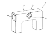
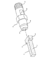
さらに、図4乃至図8を合わせて参照するように、本実施例のオイルタンク20中の潤滑油は、連結具30及びエンドカバー13の側面に結合した固定台15によりスライド10の両側のボール溝11、17に送油し、該連結具30がオイルタンク20の凸管235に挿設され、連結具30の通孔236に対応するリング状の凸縁2351にリング状溝302を形成して該リング状の凸縁2351の嵌入により係止状態にならしめ、オイルタンク20の取付け取り外すのに極めて便利である。また、該連結具30の一端に軸孔301を設置し、該軸孔301は、さらに連結具30の外リング面の両対向した貫通孔303に連通する。該連結具30の軸孔301にT字状の送油具31を強制的に押し込むことができ、また該送油具31の末端の突出した径方向部312、313は、連結具30の両対向した貫通孔303から貫出すると同時に、該連結具30の外リング面より突出している。該送油具31の軸方向部311の前端も軸孔301に突出し、送油具31の前端は、オイルタンク20の送油具22の送出部221に接触して、潤滑油が両送油具22、31によりオイルタンク20の外部まで送油することができ、該連結具30の他端は、外ねじ305を設置し、そのねじ端がカバープレート16の貫通孔161、塗布シート151及び固定台15の貫通孔154(固定台15の貫通孔、図示せず)を貫通した後、スライダ12の両側のエンドカバー13、14のいずれか一方のエンドカバー13のねじ穴131に締め付けられ、これらカバープレート16、固定台15、エンドカバー13などの部材が緊密に一体に固定される。前記固定台15は、塗布シート151を収容するための溝(図示せず)を備え、前記塗布シート151のスライド10の両側に対応するボール溝11、17は、それぞれ突出部152、153を形成して、各突出部152、153がスライダ12とスライド10との互いに摺移する際に、スライド10とを摩擦してオイルタンク20からの送油具22を連結具30の送油具31まで送出して、次に、該連結具30の送油具31から固定台15中の塗布シート151の潤滑油(脂)を釈放してスライド10の両側のボール溝11、17に回転するボールが良い潤滑が得られる。
Further, referring to FIGS. 4 to 8 together, the lubricating oil in the
以上の説明により、本発明は、以下の利点を有することがわかる。
1.組付方向が任意に変更可能:オイルタンク20中の送油具22は、オイルタンク20の内部の収容空間234の周りに分布され、左右、上下、前後方向の各位置に延伸しているので、オイルタンク20の位置は、如何に変更して潤滑油(脂)が低い場所に流れる際しても、送油具22との接触は可能であるため、送油具22の毛細原理を利用して潤滑油(脂)を送油具22の送出部221まで吸収、または送油することができ、さらに該連結具30の送油具31により潤滑油(脂)をオイルタンク20の外部まで送油することは可能である。
From the above description, it can be seen that the present invention has the following advantages.
1. Assembling direction can be arbitrarily changed: The
2.オイルタンクの正圧保持の確保:凸管235の欠口237の両側に設置された溝238は、オイルタンク20の外部の空気がオイルタンク20に入るために用いられ、オイルタンク20の内部と外部の圧力とバランスして潤滑油(脂)の液体レベルが低下した時、空気と同時に導入することにより、送油具22が毛細原理により、潤滑油(脂)を正常に送油することができる。
2. Ensuring positive pressure retention of the oil tank: The
以上説明のように、本願は、確かな実用性および進歩性を有しており、また、出願人により如何なる国内外の文献を検索しても、これと同一または近似するものがなかったため、本発明は、専利法上に関する発明の規定に確実に合致しているので、法により出願を提出して本願を発明特許として許可すべきである。 As described above, the present application has certain practical utility and inventive step, and no matter what domestic and foreign literatures are searched by the applicant, there is nothing that is the same as or similar to this. Since the invention reliably meets the provisions of the invention under patent law, the application should be filed by law and this application should be granted as an invention patent.
10 スライド 11 ボール溝
12 スライダ 13 エンドカバー
131 ねじ穴 14 エンドカバー
15 固定台 151 塗布シート
152 突出部 153 突出部
154 貫通孔 16 カバープレート
161 貫通孔 17 ボール溝
20 オイルタンク 21 閉鎖板
22 送油具 221 送出部
23 本体 230 ゴムプラグ
231 階段状縁 232 支持柱
233 欠口 234 収容空間
235 凸管 2351 リング状突縁
236 通孔 237 欠口
238 溝 239 注油孔
30 連結具 301 軸孔
302 溝 303 貫通孔
305 外ねじ 31 送油具
311 軸方向部 312 径方向部
313 径方向部
DESCRIPTION OF
Claims (5)
前記凸管の欠口の両側は、それぞれ軸方向へ凹んだ細い溝がさらに設置され、該凸管の欠口が前記送油具を承接するするために用いられ、また該両細い溝の軸方向は、該送油具に被覆され、両細い溝の径方向が凸管の通孔とオイルタンクの内部の収容空間とを連通することを特徴とする組付方向変換自在なオイルタンク及びオイルタンクを設置するリニアスライド。 The interior is provided with a storage space in which lubricating oil (grease) can be accumulated, and an oil feeding tool connected to each other is laid around the housing space. The oil feeding tool supplies the lubricating oil (grease) to the oil tank by the capillary principle. A convex pipe having a through hole extending into the internal accommodation space is installed on one side surface of the oil tank, and a protruding end of the convex pipe is installed as a closed end. An oil tank and an oil tank that have a through hole communicating with the outside of the tube and that can be changed in the direction of assembly. In the linear slide to install
A thin groove recessed in the axial direction is further provided on both sides of the notch of the convex tube, and the notch of the convex tube is used to contact the oil feeding tool. The oil tank and the oil can be changed in the direction of assembly, characterized in that the direction of the coating is covered by the oil feeding tool and the radial direction of both narrow grooves communicates the through hole of the convex tube with the accommodating space inside the oil tank. Linear slide to install the tank.
前記凸管の欠口の両側には、それぞれ軸方向へ凹んだ細い溝をさらに設置して該凸管の欠口により前記送油具を承接することができ、また、該両細い溝の軸方向が送油具に被覆され、該両細い溝の径方向が前記凸管の通孔とオイルタンクの内部の収容空間とを連通することを特徴とする組付方向変換自在なオイルタンク及びオイルタンクを設置するリニアスライド。 The slide is used so that the slider can be reciprocated on the slider, end covers are installed on both sides of the slider, and ball grooves are respectively provided on the sides of the slide corresponding to the slider balls. The side surface of one end cover is coupled in the order of a fixing base with a coating sheet, a cover plate, a coupling tool with an oil feeding tool, and an oil tank, and the coating seed is accommodated in the groove of the fixing base. Covered with a cover plate, a portion corresponding to the ball groove of the coated sheet slide is formed in the protruding portion, and each protruding portion is always kept in contact with the corresponding ball groove, and lubricating oil (grease) is kept inside the oil tank. An oiling tool connected to each other is laid around the housing space, and the oiling tool is always kept in contact with the oiling tool of the connecting tool. With application sheet A convex tube having a through-hole extending into the internal accommodation space is installed on one side of the oil tank, and the protruding end of the convex tube is installed as a closed end. An oil tank having a through hole communicating with the outside of the oil tank, and the outer ring of the convex tube is a stepped cutout with a part of the recess cut off, and the assembly direction can be freely changed to receive the oil feeding tool And in the linear slide to install the oil tank,
A thin groove recessed in the axial direction can be further installed on both sides of the notch of the convex tube so that the oil feeding tool can be contacted by the notch of the convex tube. An oil tank and oil capable of changing the direction of assembly, characterized in that the direction is covered by an oil feeding tool, and the radial direction of the two narrow grooves communicates the through hole of the convex tube and the accommodating space inside the oil tank. Linear slide to install the tank.
Priority Applications (1)
| Application Number | Priority Date | Filing Date | Title |
|---|---|---|---|
| JP2007137231A JP4542564B2 (en) | 2007-05-23 | 2007-05-23 | An oil tank that can change the direction of assembly and a linear slide to install the oil tank |
Applications Claiming Priority (1)
| Application Number | Priority Date | Filing Date | Title |
|---|---|---|---|
| JP2007137231A JP4542564B2 (en) | 2007-05-23 | 2007-05-23 | An oil tank that can change the direction of assembly and a linear slide to install the oil tank |
Publications (2)
| Publication Number | Publication Date |
|---|---|
| JP2008291902A true JP2008291902A (en) | 2008-12-04 |
| JP4542564B2 JP4542564B2 (en) | 2010-09-15 |
Family
ID=40166843
Family Applications (1)
| Application Number | Title | Priority Date | Filing Date |
|---|---|---|---|
| JP2007137231A Active JP4542564B2 (en) | 2007-05-23 | 2007-05-23 | An oil tank that can change the direction of assembly and a linear slide to install the oil tank |
Country Status (1)
| Country | Link |
|---|---|
| JP (1) | JP4542564B2 (en) |
Cited By (2)
| Publication number | Priority date | Publication date | Assignee | Title |
|---|---|---|---|---|
| JP2016156467A (en) * | 2015-02-25 | 2016-09-01 | 日本精工株式会社 | Oil supply device for rolling bearing guide device and rolling bearing guide device |
| JPWO2016157904A1 (en) * | 2015-03-31 | 2017-11-16 | 日本精工株式会社 | Oil supply device and linear motion guide device |
Citations (5)
| Publication number | Priority date | Publication date | Assignee | Title |
|---|---|---|---|---|
| JPH0446216A (en) * | 1990-06-07 | 1992-02-17 | Yamaha Corp | Rectilinear guide dustproof device |
| JPH09303392A (en) * | 1996-05-10 | 1997-11-25 | Nippon Seiko Kk | Linear movement guide bearing device with lubricating agent supplying device |
| JPH10227311A (en) * | 1996-12-09 | 1998-08-25 | Thk Kk | Lubricating oil supply system for rolling guide device |
| JP2002147453A (en) * | 2000-11-10 | 2002-05-22 | Enshu Ltd | Lubricating oil feeder and linear movement device using the same |
| JP2004340362A (en) * | 2003-04-25 | 2004-12-02 | Nsk Ltd | Lubricant supply body and linear guide equipped therewith |
-
2007
- 2007-05-23 JP JP2007137231A patent/JP4542564B2/en active Active
Patent Citations (5)
| Publication number | Priority date | Publication date | Assignee | Title |
|---|---|---|---|---|
| JPH0446216A (en) * | 1990-06-07 | 1992-02-17 | Yamaha Corp | Rectilinear guide dustproof device |
| JPH09303392A (en) * | 1996-05-10 | 1997-11-25 | Nippon Seiko Kk | Linear movement guide bearing device with lubricating agent supplying device |
| JPH10227311A (en) * | 1996-12-09 | 1998-08-25 | Thk Kk | Lubricating oil supply system for rolling guide device |
| JP2002147453A (en) * | 2000-11-10 | 2002-05-22 | Enshu Ltd | Lubricating oil feeder and linear movement device using the same |
| JP2004340362A (en) * | 2003-04-25 | 2004-12-02 | Nsk Ltd | Lubricant supply body and linear guide equipped therewith |
Cited By (2)
| Publication number | Priority date | Publication date | Assignee | Title |
|---|---|---|---|---|
| JP2016156467A (en) * | 2015-02-25 | 2016-09-01 | 日本精工株式会社 | Oil supply device for rolling bearing guide device and rolling bearing guide device |
| JPWO2016157904A1 (en) * | 2015-03-31 | 2017-11-16 | 日本精工株式会社 | Oil supply device and linear motion guide device |
Also Published As
| Publication number | Publication date |
|---|---|
| JP4542564B2 (en) | 2010-09-15 |
Similar Documents
| Publication | Publication Date | Title |
|---|---|---|
| US7614790B2 (en) | Linear driving device with a self-lubricating assembly | |
| US6250804B1 (en) | Self-lubricating linear guide apparatus | |
| JP4625483B2 (en) | Linear drive module with self-lubricating unit | |
| US20170072178A1 (en) | Tattoo needle tip with capillary ink reservoir and combined device thereof | |
| JP2008082433A (en) | Linear guide unit | |
| TWM519693U (en) | Linear sliding rail and its self-lubricating module | |
| US7909512B2 (en) | Lubricating member for linear motion rolling guide unit and slider for linear motion rolling guide unit using the lubricating member | |
| US10107336B2 (en) | Oil supply device and linear motion guide device | |
| JP2008291902A (en) | Oil tank freely changing assembling direction and linear slide for installing oil tank | |
| JP2005256901A (en) | Self-lubrication type lubricator | |
| CN204127113U (en) | Linear Moving Module and certainly moisten assembly | |
| JP5045055B2 (en) | Ball screw device | |
| CN103184662A (en) | Front shaft sleeve assembly of lower shaft | |
| JPWO2004020872A1 (en) | Ball screw | |
| JP2016048085A (en) | Linear motion guide device | |
| US20060102427A1 (en) | Lubricant supply unit | |
| JP2011052700A (en) | Lubricating oil supply device and motion guide device using this | |
| JP2007057104A (en) | Straight line guiding device | |
| CN201902448U (en) | Linear movement module with self-lubricating function | |
| JP6650226B2 (en) | Linear motion guide unit | |
| JP2002147453A (en) | Lubricating oil feeder and linear movement device using the same | |
| US3013847A (en) | Lubricating device | |
| JP6055345B2 (en) | Linear motion guide unit with oil storage plate | |
| JP2017141950A (en) | Oil supply device for rolling bearing guide device, rolling bearing guide device | |
| JP4304086B2 (en) | Linear guideway self-lubricating module |
Legal Events
| Date | Code | Title | Description |
|---|---|---|---|
| A977 | Report on retrieval |
Free format text: JAPANESE INTERMEDIATE CODE: A971007 Effective date: 20090716 |
|
| A131 | Notification of reasons for refusal |
Free format text: JAPANESE INTERMEDIATE CODE: A131 Effective date: 20090819 |
|
| A601 | Written request for extension of time |
Free format text: JAPANESE INTERMEDIATE CODE: A601 Effective date: 20091118 |
|
| A602 | Written permission of extension of time |
Free format text: JAPANESE INTERMEDIATE CODE: A602 Effective date: 20091124 |
|
| A521 | Request for written amendment filed |
Free format text: JAPANESE INTERMEDIATE CODE: A523 Effective date: 20091207 |
|
| TRDD | Decision of grant or rejection written | ||
| A01 | Written decision to grant a patent or to grant a registration (utility model) |
Free format text: JAPANESE INTERMEDIATE CODE: A01 Effective date: 20100601 |
|
| A01 | Written decision to grant a patent or to grant a registration (utility model) |
Free format text: JAPANESE INTERMEDIATE CODE: A01 |
|
| A61 | First payment of annual fees (during grant procedure) |
Free format text: JAPANESE INTERMEDIATE CODE: A61 Effective date: 20100625 |
|
| R150 | Certificate of patent or registration of utility model |
Ref document number: 4542564 Country of ref document: JP Free format text: JAPANESE INTERMEDIATE CODE: R150 Free format text: JAPANESE INTERMEDIATE CODE: R150 |
|
| FPAY | Renewal fee payment (event date is renewal date of database) |
Free format text: PAYMENT UNTIL: 20130702 Year of fee payment: 3 |
|
| R250 | Receipt of annual fees |
Free format text: JAPANESE INTERMEDIATE CODE: R250 |
|
| R250 | Receipt of annual fees |
Free format text: JAPANESE INTERMEDIATE CODE: R250 |
|
| R250 | Receipt of annual fees |
Free format text: JAPANESE INTERMEDIATE CODE: R250 |
|
| R250 | Receipt of annual fees |
Free format text: JAPANESE INTERMEDIATE CODE: R250 |
|
| R250 | Receipt of annual fees |
Free format text: JAPANESE INTERMEDIATE CODE: R250 |
|
| R250 | Receipt of annual fees |
Free format text: JAPANESE INTERMEDIATE CODE: R250 |
|
| R250 | Receipt of annual fees |
Free format text: JAPANESE INTERMEDIATE CODE: R250 |
|
| R250 | Receipt of annual fees |
Free format text: JAPANESE INTERMEDIATE CODE: R250 |
|
| R250 | Receipt of annual fees |
Free format text: JAPANESE INTERMEDIATE CODE: R250 |
|
| R250 | Receipt of annual fees |
Free format text: JAPANESE INTERMEDIATE CODE: R250 |
|
| R250 | Receipt of annual fees |
Free format text: JAPANESE INTERMEDIATE CODE: R250 |