JP2008287769A - Disk device - Google Patents
Disk device Download PDFInfo
- Publication number
- JP2008287769A JP2008287769A JP2007129583A JP2007129583A JP2008287769A JP 2008287769 A JP2008287769 A JP 2008287769A JP 2007129583 A JP2007129583 A JP 2007129583A JP 2007129583 A JP2007129583 A JP 2007129583A JP 2008287769 A JP2008287769 A JP 2008287769A
- Authority
- JP
- Japan
- Prior art keywords
- base
- ramp
- lamp
- recording medium
- head
- Prior art date
- Legal status (The legal status is an assumption and is not a legal conclusion. Google has not performed a legal analysis and makes no representation as to the accuracy of the status listed.)
- Pending
Links
Images


Classifications
-
- G—PHYSICS
- G11—INFORMATION STORAGE
- G11B—INFORMATION STORAGE BASED ON RELATIVE MOVEMENT BETWEEN RECORD CARRIER AND TRANSDUCER
- G11B21/00—Head arrangements not specific to the method of recording or reproducing
- G11B21/16—Supporting the heads; Supporting the sockets for plug-in heads
- G11B21/22—Supporting the heads; Supporting the sockets for plug-in heads while the head is out of operative position
Abstract
Description
この発明は、ディスク装置に関し、特に、ランプロード機構を備えた磁気ディスク装置に関する。 The present invention relates to a disk device, and more particularly to a magnetic disk device having a ramp load mechanism.
近年、コンピュータの外部記録装置や画像記録装置として磁気ディスク装置、光ディスク装置などのディスク装置が広く用いられている。
ディスク装置として、例えば、磁気ディスク装置は、一般に、上面の開口した矩形箱状のベースと、複数のねじによりベースにねじ止めされてベースの上面開口を閉塞したトップカバーと、を有している。ベース内には、記録媒体としての磁気ディスク、この磁気ディスクを支持および回転させるスピンドルモータ、磁気ディスクに対して情報の書き込み、読み出しを行なう複数の磁気ヘッド、これらの磁気ヘッドを磁気ディスクに対して移動自在に支持したヘッドアクチュエータ、ヘッドアクチュエータを回動および位置決めするボイスコイルモータ、ヘッドIC等を有する基板ユニット等が設けられている。
In recent years, disk devices such as magnetic disk devices and optical disk devices have been widely used as external recording devices and image recording devices for computers.
As a disk device, for example, a magnetic disk device generally has a rectangular box-shaped base having an open top surface, and a top cover screwed to the base by a plurality of screws to close the top surface opening of the base. . In the base, a magnetic disk as a recording medium, a spindle motor for supporting and rotating the magnetic disk, a plurality of magnetic heads for writing and reading information on the magnetic disk, and these magnetic heads to the magnetic disk A head actuator that is movably supported, a voice coil motor that rotates and positions the head actuator, a substrate unit having a head IC, and the like are provided.
また、近年、携帯可能な小型のパーソナルコンピュータが普及しつつあり、この種のパーソナルコンピュータに搭載される磁気ディスク装置は、携帯時における衝撃等に対する信頼性の向上が求められている。 In recent years, small portable personal computers have become widespread, and magnetic disk devices mounted on this type of personal computer are required to have improved reliability against impacts when carried.
そこで、磁気ディスク装置の非動作時に磁気ヘッドを保持する機構として、ランプロード機構を備えたものが提供されている(例えば、特許文献1)。このランプロード機構は、サスペンションの先端からタブと、一部が磁気ディスクの外周と重なるようにベース上に配置されたランプと、を備えている。そして、磁気ディスク装置が非動作状態に移行する時、ヘッドアクチュエータが磁気ディスクの外周に回動されると、サスペンションのタブがランプに乗り上げ、磁気ヘッドは、磁気ディスク表面から離間した位置に保持される。
上述した磁気ディスク装置において、ランプロード機構のランプは、ベースの外側からねじ込まれたねじ、およびトップカバーの外側からねじ込まれたねじにより、ケースに位置決め固定されている。 In the magnetic disk device described above, the ramp of the ramp load mechanism is positioned and fixed to the case by a screw screwed from the outside of the base and a screw screwed from the outside of the top cover.
しかしながら、上記のようにランプをねじ止めによって所定位置に固定する場合、ランプを所定位置に保持した状態で、上下からねじ止めする必要があり、組み立て作業が面倒となる。また、ベースおよびトップカバーにねじを通すための透孔を設ける必要があり、ケースの加工数が増加する。 However, when the lamp is fixed at a predetermined position by screwing as described above, it is necessary to screw the lamp from above and below with the lamp held at the predetermined position, which makes the assembly work troublesome. In addition, it is necessary to provide through holes for passing screws through the base and the top cover, which increases the number of cases processed.
この発明は以上の点に鑑みなされたもので、その目的は、ランプを所定位置に容易に固定することができ、組み立て性の向上および製造コストの低減を図ることが可能な磁気ディスク装置を提供することにある。 The present invention has been made in view of the above points, and an object of the present invention is to provide a magnetic disk device capable of easily fixing a lamp at a predetermined position, and improving assembly and reducing manufacturing costs. There is to do.
この発明の態様に係る磁気ディスク装置は、底壁を有したベース、および押圧部を有しているとともに前記ベースに固定されたトップカバーを備えたケースと、前記ベースに設けられたモータと、前記モータに回転自在に支持されたディスク状の記録媒体と、前記記録媒体に対して情報処理を行うヘッドと、前記ベース上に設けられ、前記ヘッドを前記記録媒体に対して移動自在に支持したヘッドアクチュエータと、前記ヘッドが前記記録媒体から離間した停止位置に前記ヘッドアクチュエータを支持するランプロード機構と、を具備し、
上記ランプロード機構は、上記記録媒体の外周側に設けられたランプと、前記ヘッドアクチュエータから延出し、前記ヘッドが記録媒体の外周部に移動した際、前記ランプに乗り上げる係合部と、を備え、前記ランプは、凹所およびこの凹所を跨いで設けられ弾性変形可能なブリッジ部を有し、前記ブリッジ部が前記トップカバーの押圧部に弾性的に押圧された状態で、前記ベースとトップカバーとの間に固定されている。
A magnetic disk device according to an aspect of the present invention includes a base having a bottom wall, a case having a pressing portion and having a top cover fixed to the base, a motor provided on the base, A disk-shaped recording medium that is rotatably supported by the motor, a head that performs information processing on the recording medium, and a head that is provided on the base and that is movably supported with respect to the recording medium A head actuator; and a ramp load mechanism that supports the head actuator at a stop position where the head is separated from the recording medium,
The ramp loading mechanism includes a ramp provided on the outer peripheral side of the recording medium, and an engaging portion that extends from the head actuator and rides on the ramp when the head moves to the outer peripheral portion of the recording medium. The lamp includes a recess and a bridge portion that is provided across the recess and can be elastically deformed. The bridge portion is elastically pressed by the pressing portion of the top cover. It is fixed between the cover.
この発明の態様によれば、ねじを用いることなくランプを所定位置に容易に固定することができ、組み立て性の向上および製造コストの低減を図ることが可能な磁気ディスク装置を提供することができる。 According to the aspect of the present invention, it is possible to provide a magnetic disk device that can easily fix the lamp at a predetermined position without using a screw, and can improve the assembling property and reduce the manufacturing cost. .
以下図面を参照しながら、この発明をディスク装置としてのハードディスクドライブ(以下HDDと称する)に適用した実施形態について詳細に説明する。
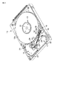
図1はHDD全体の構成を分解して示す斜視図、図2はトップカバーを取外してHDDの内部構成を示す斜視図である。
An embodiment in which the present invention is applied to a hard disk drive (hereinafter referred to as HDD) as a disk device will be described in detail below with reference to the drawings.
FIG. 1 is an exploded perspective view showing the entire structure of the HDD, and FIG. 2 is a perspective view showing the internal structure of the HDD with the top cover removed.
図1および図2に示すように、HDDは、偏平な矩形状のケース8を備えている。このケース8は、上面の開口した矩形箱状のベース10と、複数のねじによりベースにねじ止めされベースの上端開口を閉塞する矩形板状のトップカバー11と、を有している。ベース10は、矩形板状の底壁10aおよび底壁の周縁に沿って立設された側壁10bを一体に有している。トップカバー11は、後述するランプロード機構のランプに対応する位置に設けられた押圧部を有している。この押圧部は、トップカバー11の一部をベース10側に突出させて形成された位置決めボス7を有している。
As shown in FIGS. 1 and 2, the HDD includes a flat
ベース10上には、記録媒体として例えば、2枚の磁気ディスク12a、12b、磁気ディスクを支持および回転させるスピンドルモータ13、磁気ディスクに対して情報の記録、再生を行なう複数の磁気ヘッド33、これらの磁気ヘッドを磁気ディスク12a、12bに対して移動自在に支持したヘッドアクチュエータ14、ヘッドアクチュエータを回動および位置決めするボイスコイルモータ(以下VCMと称する)16が設けられている。また、ベース10上には、磁気ヘッド33が磁気ディスク12a、12bの最外周に移動した際、磁気ヘッドを磁気ディスクから離間した位置に保持するランプロード機構18、ヘッドアクチュエータ14を退避位置に保持するイナーシャラッチ機構20、およびプリアンプ等の回路部品が実装されたフレキシブルプリント回路基板ユニット(以下、FPCユニットと称する)17が配設されている。スピンドルモータ13、ヘッドアクチュエータ14、VCM16等はベース10の底壁10aの内面上に設けられている。
On the
磁気ディスク12a、12bは、例えば、直径65mm(2.5インチ)に形成され、スピンドルモータ13のハブ13aに同軸的に嵌合され、クランプばね21によりクランプされている。これにより、磁気ディスク12a、12bは、ハブ13aの外周に固定され、ハブと一体的に回転可能に支持されている。磁気ディスク12a、12bは、スピンドルモータ13により所定の速度で回転される。
The
ヘッドアクチュエータ14は、ベース10の底壁10a上に立設された軸受組立体24と、この軸受組立体に支持された4本のアーム27と、各アームに支持された磁気ヘッド組立体30と、を備えている。各磁気ヘッド組立体30は、板ばねによって形成された細長いサスペンション32と、サスペンションの延出端に固定された磁気ヘッド33と、を備えている。
The
ヘッドアクチュエータ14をケース8に組み込んだ状態において、各磁気ディスク12a、12bは2本のアーム27間に位置している。そして、サスペンション32に取り付けられた磁気ヘッド33は、磁気ディスク12a、12bの上面および下面にそれぞれ対向し、磁気ディスクを両面側から挟持している。各磁気ヘッド33は、サスペンション32のばね力により磁気ディスク表面に向かって所定のヘッド荷重が印加されている。
In a state where the
VCM16は、ヘッドアクチュエータ14に設けられたボイスコイル15と、底壁10a上に固定されボイスコイルと対向した一対のヨーク34、および一方のヨークに固定された磁石とを有している。
The VCM 16 includes a
FPCユニット17は、ベース10の底壁10a上に固定された基板本体36を有し、この基板本体上には、複数の電子部品およびコネクタ等が実装されている。FPCユニット17は、基板本体36とヘッドアクチュエータ14とを電気的に接続した帯状のメインフレキシブルプリント回路基板38を有している。ヘッドアクチュエータ14に支持された各磁気ヘッド33は、アーム27上に設けられた図示しない中継FPCおよびメインフレキシブルプリント回路基板38を介してFPCユニット17に電気的に接続されている。磁気ディスク12a、12bの近傍で、ベース10の周縁部には、図示しない呼吸フィルタおよび循環フィルタ等が設けられている。
The FPC
ベース10の底壁10a外面には、FPCユニット17を介して、スピンドルモータ13、VCM16、および磁気ヘッド33の動作を制御するプリント回路基板40がねじ止めされ、ベースの底壁10aと対向している。プリント回路基板40上には、コネクタ41を含む多数の電子部品が実装されている。プリント回路基板40は、電子部品が実装されている面がベース10の底壁10a外面と対向した状態で配置されている。
A printed
ランプロード機構18は、磁気ディスク12a、12bの外周側でベース10の底壁10a上に設けられたランプ50と、ヘッドアクチュエータ14の各ヘッドサスペンション32の先端から延出した係合部としてのタブ53と、を有している。HDDの非作動時、磁気ヘッド33が磁気ディスク12a、12bの外周から外れて所定の停止位置に移動すると、各タブ53はランプ50に乗り上げる。これにより、磁気ヘッド33は、磁気ディスク12a、12bから離間した位置に保持される。
The
図3および図4はベース10の底壁上の所定位置に配置されたランプを示し、図5、図6、図7は、それぞれ異なる方向から見たランプの外観を示している。図3ないし図7に示すように、ランプ50は、ブロック状に形成された本体52を備えている。本体52の一側部には、4つのサスペンション32に設けられたタブ53をそれぞれガイドする4つのガイド面56a、56b、56c、56dが形成されている。これらのガイド面56a〜56dは、磁気ディスク12a、12bの軸方向に沿って所定の間隔をおいて並び、それぞれ対応するサスペンション32の高さに合わせて配置されている。また、各ガイド面56a〜56dは、磁気ディスク12a、12bのほぼ半径方向に沿って、磁気ディスクの外周縁近傍まで延びているとともに、サスペンション32に設けられたタブ53の移動経路上に配置されている。そして、上から1番目、3番目のサスペンション32に対応する2つのガイド面56a、56cは、上方を向いて形成され、2番目、4番目のサスペンション32に対応する2つのガイド面56b、56dは、下方を向いて形成されている。
3 and 4 show the lamps arranged at predetermined positions on the bottom wall of the
各ガイド面56a〜56dは、磁気ディスク12a、12bに向って傾斜し磁気ヘッド33を磁気ディスク上にロード、アンロードするための傾斜面と、傾斜面に続いて磁気ディスク表面と平行に延びる平坦部と、を有している。
Each of the
また、本体52の一側部には、ガイド面56a〜56dと所定の隙間を置いて対向したタブ押え58と、隣合うタブ押え板間に位置しているとともに、本体52から突出したジンバル押え60と、が一体に形成されている。
Also, on one side of the
本体52にはほぼ矩形状の凹所62が形成されている。この凹所62は、ガイド面56a〜56dと反対側に位置した本体52の他側部および本体の上面に開口している。ランプ50は、凹所62を跨いで設けられ弾性変形可能なブリッジ部64を有している。ブリッジ部64は所定幅を有した板状に形成され、その両端部が本体52に固定されている。ブリッジ部64は、本体52の上面よりも僅かに上方、つまり、トップカバー11側に一段高い位置に設けられ、凹所62およびトップカバー11に対向しているとともに、底壁10aおよびトップカバー11とほぼ平行に延びている。ブリッジ部64の中央部には、トップカバー11の位置決めボス7と係合する係合孔66が形成されている。
A substantially
ブリッジ部64は、本体52に連結された両端部を中心として、ベース10の底壁10aと直交する方向に弾性変形可能に形成されている。また、ブリッジ部64は、所定の幅を有していることから、底壁10aと平行な面方向の変形およびねじれが規制されている。ブリッジ部64は、本体52と同一材料、例えば、合成樹脂により、本体52と一体に成型されている。
The
図7に示すように、ランプ50の本体52の下端部は、ベース10の底壁10aに当接および係合する係合端部68を構成している。この係合端部68は、本体52から僅かに突出し、平坦なほぼ矩形状に形成されている。また、係合端部68は、弾性変形可能な係合爪70を有し、係合爪70の延出端には位置決め凸部72が形成されている。
As shown in FIG. 7, the lower end portion of the
図8、図9、図10、図11に示すように、ベース10の底壁10a上には、平坦なランプ載置部74が形成されている。ランプ載置部74は、磁気ディスク12a、12bの外側で、かつ、ベース10の側壁10bに隣接して形成されている。ランプ載置部74には、細長い直線状のガイドレール76が突設されている。ガイドレール76は、磁気ディスク12a、12bと交差する方向、ここでは、側壁10bと平行な方向に延びている。ガイドレール76の一端部には、係合部としての位置決め凹所77が形成されている。また、側壁10bには、ランプ載置部74に隣接して位置しランプ50に当接する当接部78a、78bが形成されている。一方の当接部78aは、ガイドレール76とほぼ平行に対向し、他方の当接部78bはガイドレールと直交する方向に延びている。
As shown in FIGS. 8, 9, 10, and 11, a flat
HDDの組み立て時において、ランプ50は以下の工程によりケース8に取り付けられる。図8に示すように、まず、ベース10にスピンドルモータ13および2枚の磁気ディスク12a、12bが取り付けられている。続いて、図10および図11に示すように、
ランプ50をベース10のランプ載置部74上に上方から載置し、ランプの係合端部68を底壁10a上に当接させるとともに、ガイドレール76と当接部78aとの間に配置する。次いで、ガイドレール76をガイドとして、ランプ50を磁気ディスク12a、12b側にスライドさせ、ランプが当接部78bに当接する所定位置まで移動させる。この間、係合端部68に設けられた係合爪70が弾性変形した後、ランプ50が所定位置まで移動した時点で、係合凸部72がガイドレール76の位置決め凹所77に係合する。
When the HDD is assembled, the
The
これにより、ランプ50は、その係合端部68がランプ載置部74上に面接触し、かつ、ガイドレール76と当接部78aとの間に挟持された状態で位置決めされる。同時に、係合凸部72がガイドレール76の位置決め凹所77に係合することにより、ランプ50のスライド方向の移動が規制され、ランプは当接部78bに当接した所定位置に保持される。また、所定位置において、ランプ50の先端部は、磁気ディスク12a、12bの周縁部と重なった位置に挿入されている。
As a result, the
ランプ50をランプ載置部74に装着した後、前述したヘッドアクチュエータ14、VCM16等の他の構成要素がベース10に装着される。続いて、図10および図12に示すように、トップカバー11をベース10にねじ止めし、ベースの上部開口を閉塞する。この際、トップカバー11に設けられた位置決めボス7は、ランプ50のブリッジ部64の係合孔66に係合し、ブリッジ部64をベース10側に押圧する。ブリッジ部64は、ベース10側に弾性変形し、ランプ50全体をベース10に押し付け固定する。また、位置決めボス7が係合孔66に係合することにより、ブリッジ部64は底壁10aの平面方向に位置決めされる。これにより、ランプ50は、ベース10とトップカバー11とに挟持された状態で、所定位置に位置決めされ固定される。更に、ブリッジ部64の両端部でランプ50を押圧することにより、ランプの傾きおよびずれが防止される。
After the
以上のように構成されたHDDによれば、ブリッジ部64の弾性およびトップカバー11を利用することにより、ねじを用いることなくランプ50をベースとトップカバーとの間に挟持固定することができる。これにより、ねじ止めする場合に比較して、ランプを所定位置に容易に固定することができ、組み立て性の向上を図ることができる。同時に、ベースおよびトップカバーにねじ止め用の透孔等を形成する必要がなく、加工数およびねじを削減し製造コストの低減を図ることができる。同時に、ケースの気密性向上を図ることが可能となる。
According to the HDD configured as described above, the
なお、本発明は上記実施形態そのままに限定されるものではなく、実施段階ではその要旨を逸脱しない範囲で構成要素を変形して具体化できる。また、上記実施形態に開示されている複数の構成要素の適宜な組み合わせにより、種々の発明を形成できる。例えば、実施形態に示される全構成要素から幾つかの構成要素を削除してもよい。さらに、異なる実施形態にわたる構成要素を適宜組み合わせてもよい。 Note that the present invention is not limited to the above-described embodiment as it is, and can be embodied by modifying the constituent elements without departing from the scope of the invention in the implementation stage. In addition, various inventions can be formed by appropriately combining a plurality of constituent elements disclosed in the embodiment. For example, some components may be deleted from all the components shown in the embodiment. Furthermore, constituent elements over different embodiments may be appropriately combined.
例えば、HDDにおいて、磁気ディスクの枚数は2枚に限らず、必要に応じて増減可能である。また、ランプのブリッジ部は、ランプの本体と一体成型する構成に限らず、ランプの本体と異なる材料で形成してもよい。図13に示す実施形態によれば、ブリッジ部64は、本体52と異なる樹脂あるいは金属等により形成され、その両端部が本体52に接着あるいは他の方法により固定されている。このようなランプを用いた場合でも、前述した実施形態と同様の作用効果を得ることができる。
For example, in the HDD, the number of magnetic disks is not limited to two, and can be increased or decreased as necessary. Further, the bridge portion of the lamp is not limited to a configuration in which the lamp is integrally formed with the lamp body, and may be formed of a material different from that of the lamp body. According to the embodiment shown in FIG. 13, the
7…位置決めボス、10…ベース、10a…底壁、10b…側壁、
11…トップカバー、12…磁気ディスク、13…スピンドルモータ、
14…ヘッドアクチュエータ、16…VCM、18…ランプロード機構、
24…軸受組立体、33…磁気ヘッド、50…ランプ、52…本体、62…凹所、
64…ブリッジ部、66…係合孔、70…係合爪、72…位置決め凸部、
74…ランプ載置部、76…ガイドレール、77…位置決め凹所、
78a、78b…当接部
7: positioning boss, 10 ... base, 10a ... bottom wall, 10b ... side wall,
11 ... Top cover, 12 ... Magnetic disk, 13 ... Spindle motor,
14 ... Head actuator, 16 ... VCM, 18 ... Ramp load mechanism,
24 ... Bearing assembly, 33 ... Magnetic head, 50 ... Lamp, 52 ... Main body, 62 ... Recess,
64 ... Bridge part, 66 ... engagement hole, 70 ... engagement claw, 72 ... positioning convex part,
74: Lamp mounting portion, 76: Guide rail, 77: Positioning recess,
78a, 78b ... contact part
Claims (6)
前記ベースに設けられたモータと、
前記モータに回転自在に支持されたディスク状の記録媒体と、
前記記録媒体に対して情報処理を行うヘッドと、
前記ベース上に設けられ、前記ヘッドを前記記録媒体に対して移動自在に支持したヘッドアクチュエータと、
前記ヘッドが前記記録媒体から離間した停止位置に前記ヘッドアクチュエータを支持するランプロード機構と、を具備し、
上記ランプロード機構は、上記記録媒体の外周側に設けられたランプと、前記ヘッドアクチュエータから延出し、前記ヘッドが記録媒体の外周部に移動した際、前記ランプに乗り上げる係合部と、を備え、
前記ランプは、凹所およびこの凹所を跨いで設けられ弾性変形可能なブリッジ部を有し、前記ブリッジ部が前記トップカバーの押圧部に弾性的に押圧された状態で、前記ベースとトップカバーとの間に固定されている磁気ディスク装置。 A base having a bottom wall, and a case having a pressing portion and a top cover fixed to the base;
A motor provided on the base;
A disc-shaped recording medium rotatably supported by the motor;
A head for performing information processing on the recording medium;
A head actuator provided on the base and supporting the head movably with respect to the recording medium;
A ramp loading mechanism for supporting the head actuator at a stop position where the head is separated from the recording medium,
The ramp loading mechanism includes a ramp provided on the outer peripheral side of the recording medium, and an engaging portion that extends from the head actuator and rides on the ramp when the head moves to the outer peripheral portion of the recording medium. ,
The lamp includes a recess and a bridge portion that is provided across the recess and can be elastically deformed, and the base and the top cover are in a state where the bridge portion is elastically pressed by the pressing portion of the top cover. Magnetic disk unit fixed between and.
前記ランプは、前記ランプ載置部上に載置されているとともに前記ガイドレールと前記当接部との間に保持された係合端部と、前記ガイドレールの係合部と弾性的に係合し前記ガイドレールの延出方向に沿った前記ランプの移動を規制した位置決め凸部と、を備えている請求項1に記載の磁気ディスク装置。 The base includes a side wall erected along a peripheral edge of the bottom wall, a flat lamp mounting portion formed on the bottom wall, and a direction formed on the lamp mounting portion and intersecting the recording medium. A guide rail having an engaging portion and an abutting portion provided on the side wall and facing the guide rail,
The lamp is mounted on the lamp mounting portion, and is elastically engaged with an engagement end held between the guide rail and the contact portion, and an engagement portion of the guide rail. The magnetic disk apparatus according to claim 1, further comprising a positioning protrusion that restricts movement of the ramp along the extending direction of the guide rail.
Priority Applications (3)
| Application Number | Priority Date | Filing Date | Title |
|---|---|---|---|
| JP2007129583A JP2008287769A (en) | 2007-05-15 | 2007-05-15 | Disk device |
| CNA2008100912755A CN101308664A (en) | 2007-05-15 | 2008-04-28 | Disk device |
| US12/110,680 US20080285175A1 (en) | 2007-05-15 | 2008-04-28 | Disk device |
Applications Claiming Priority (1)
| Application Number | Priority Date | Filing Date | Title |
|---|---|---|---|
| JP2007129583A JP2008287769A (en) | 2007-05-15 | 2007-05-15 | Disk device |
Publications (1)
| Publication Number | Publication Date |
|---|---|
| JP2008287769A true JP2008287769A (en) | 2008-11-27 |
Family
ID=40027227
Family Applications (1)
| Application Number | Title | Priority Date | Filing Date |
|---|---|---|---|
| JP2007129583A Pending JP2008287769A (en) | 2007-05-15 | 2007-05-15 | Disk device |
Country Status (3)
| Country | Link |
|---|---|
| US (1) | US20080285175A1 (en) |
| JP (1) | JP2008287769A (en) |
| CN (1) | CN101308664A (en) |
Cited By (2)
| Publication number | Priority date | Publication date | Assignee | Title |
|---|---|---|---|---|
| US20130208415A1 (en) * | 2010-05-07 | 2013-08-15 | Mmi Precision Forming Pte Ltd | Low Cost High Performance Hard Drive Base |
| CN104210992A (en) * | 2014-08-19 | 2014-12-17 | 苏州汇科机电设备有限公司 | Auxiliary equipment jacking and adjusting device for electronic furnace |
Families Citing this family (5)
| Publication number | Priority date | Publication date | Assignee | Title |
|---|---|---|---|---|
| US8493690B1 (en) * | 2011-12-29 | 2013-07-23 | HGST Netherlands B.V. | Load-unload ramp structure with cantilevered fin portion configured to reduce drop shock in a hard-disk drive |
| US9536552B1 (en) | 2015-07-31 | 2017-01-03 | Seagate Technology Llc | Retaining slide-in ramp for hard disk drive |
| JP2021114348A (en) * | 2020-01-17 | 2021-08-05 | 株式会社東芝 | Suspension assembly and disk device |
| JP2023046037A (en) * | 2021-09-22 | 2023-04-03 | 株式会社東芝 | disk device |
| JP2024042944A (en) * | 2022-09-16 | 2024-03-29 | 株式会社東芝 | Disk device |
-
2007
- 2007-05-15 JP JP2007129583A patent/JP2008287769A/en active Pending
-
2008
- 2008-04-28 US US12/110,680 patent/US20080285175A1/en not_active Abandoned
- 2008-04-28 CN CNA2008100912755A patent/CN101308664A/en active Pending
Cited By (3)
| Publication number | Priority date | Publication date | Assignee | Title |
|---|---|---|---|---|
| US20130208415A1 (en) * | 2010-05-07 | 2013-08-15 | Mmi Precision Forming Pte Ltd | Low Cost High Performance Hard Drive Base |
| US8947825B2 (en) * | 2010-05-07 | 2015-02-03 | Mmi Precision Forming Pte Ltd. | Low cost high performance hard drive base |
| CN104210992A (en) * | 2014-08-19 | 2014-12-17 | 苏州汇科机电设备有限公司 | Auxiliary equipment jacking and adjusting device for electronic furnace |
Also Published As
| Publication number | Publication date |
|---|---|
| CN101308664A (en) | 2008-11-19 |
| US20080285175A1 (en) | 2008-11-20 |
Similar Documents
| Publication | Publication Date | Title |
|---|---|---|
| JP4309417B2 (en) | Disk unit | |
| CN111724819B (en) | Disk device | |
| JP2006294170A (en) | Disk device | |
| JP2008287769A (en) | Disk device | |
| US9286924B1 (en) | Flexible printed circuit assembly and disk drive including the same | |
| US7889459B2 (en) | HDD and HDD stack assembly with head suspension having multiple combination parts and spacer | |
| JP2007207300A (en) | Disk drive | |
| JP4131980B2 (en) | Disk device and assembling method thereof | |
| US11240919B2 (en) | Connecting device and disk device | |
| US20050243459A1 (en) | Disk drive structure having holding portions for protecting a control circuit board | |
| JP4256444B1 (en) | Disk drive | |
| JP2013149326A (en) | Disk device | |
| JP2019169213A (en) | Disk device and assembly method of disk device | |
| JP5033005B2 (en) | Hard disk drive substrate holding device and actuator assembly | |
| JP2005293717A (en) | Insulated sheet and disc device equipped with this | |
| JP4908615B2 (en) | Head suspension assembly and disk drive equipped with the same | |
| JP4869423B2 (en) | Head gimbal assembly and disk device provided with the same | |
| EP2031585A1 (en) | Arm plate, head stack assembly comprising the same, and hard disk drive comprising the head stack assembly | |
| JPH09251733A (en) | Magnetic disk device | |
| JP3788865B2 (en) | Magnetic disk unit | |
| JP2004086984A (en) | Head assembly, disk device, and method for manufacturing head assembly | |
| JP3464992B2 (en) | Disk unit | |
| JP2008305454A (en) | Head actuator assembly, disk device provided with the same, and manufacturing method of head actuator assembly | |
| JP2007087491A (en) | Disk device | |
| JP2000011571A (en) | Magnetic disk device |