JP2005293717A - Insulating sheet and disk device provided with the same - Google Patents
Insulating sheet and disk device provided with the same Download PDFInfo
- Publication number
- JP2005293717A JP2005293717A JP2004107343A JP2004107343A JP2005293717A JP 2005293717 A JP2005293717 A JP 2005293717A JP 2004107343 A JP2004107343 A JP 2004107343A JP 2004107343 A JP2004107343 A JP 2004107343A JP 2005293717 A JP2005293717 A JP 2005293717A
- Authority
- JP
- Japan
- Prior art keywords
- damping material
- bottom wall
- damping
- circuit board
- printed circuit
- Prior art date
- Legal status (The legal status is an assumption and is not a legal conclusion. Google has not performed a legal analysis and makes no representation as to the accuracy of the status listed.)
- Pending
Links
Images
Classifications
-
- G—PHYSICS
- G11—INFORMATION STORAGE
- G11B—INFORMATION STORAGE BASED ON RELATIVE MOVEMENT BETWEEN RECORD CARRIER AND TRANSDUCER
- G11B33/00—Constructional parts, details or accessories not provided for in the other groups of this subclass
- G11B33/12—Disposition of constructional parts in the apparatus, e.g. of power supply, of modules
- G11B33/121—Disposition of constructional parts in the apparatus, e.g. of power supply, of modules the apparatus comprising a single recording/reproducing device
-
- G—PHYSICS
- G11—INFORMATION STORAGE
- G11B—INFORMATION STORAGE BASED ON RELATIVE MOVEMENT BETWEEN RECORD CARRIER AND TRANSDUCER
- G11B25/00—Apparatus characterised by the shape of record carrier employed but not specific to the method of recording or reproducing, e.g. dictating apparatus; Combinations of such apparatus
- G11B25/04—Apparatus characterised by the shape of record carrier employed but not specific to the method of recording or reproducing, e.g. dictating apparatus; Combinations of such apparatus using flat record carriers, e.g. disc, card
- G11B25/043—Apparatus characterised by the shape of record carrier employed but not specific to the method of recording or reproducing, e.g. dictating apparatus; Combinations of such apparatus using flat record carriers, e.g. disc, card using rotating discs
-
- H—ELECTRICITY
- H05—ELECTRIC TECHNIQUES NOT OTHERWISE PROVIDED FOR
- H05K—PRINTED CIRCUITS; CASINGS OR CONSTRUCTIONAL DETAILS OF ELECTRIC APPARATUS; MANUFACTURE OF ASSEMBLAGES OF ELECTRICAL COMPONENTS
- H05K1/00—Printed circuits
- H05K1/02—Details
- H05K1/0271—Arrangements for reducing stress or warp in rigid printed circuit boards, e.g. caused by loads, vibrations or differences in thermal expansion
-
- H—ELECTRICITY
- H05—ELECTRIC TECHNIQUES NOT OTHERWISE PROVIDED FOR
- H05K—PRINTED CIRCUITS; CASINGS OR CONSTRUCTIONAL DETAILS OF ELECTRIC APPARATUS; MANUFACTURE OF ASSEMBLAGES OF ELECTRICAL COMPONENTS
- H05K1/00—Printed circuits
- H05K1/02—Details
- H05K1/0213—Electrical arrangements not otherwise provided for
- H05K1/0254—High voltage adaptations; Electrical insulation details; Overvoltage or electrostatic discharge protection ; Arrangements for regulating voltages or for using plural voltages
- H05K1/0256—Electrical insulation details, e.g. around high voltage areas
-
- H—ELECTRICITY
- H05—ELECTRIC TECHNIQUES NOT OTHERWISE PROVIDED FOR
- H05K—PRINTED CIRCUITS; CASINGS OR CONSTRUCTIONAL DETAILS OF ELECTRIC APPARATUS; MANUFACTURE OF ASSEMBLAGES OF ELECTRICAL COMPONENTS
- H05K2201/00—Indexing scheme relating to printed circuits covered by H05K1/00
- H05K2201/20—Details of printed circuits not provided for in H05K2201/01 - H05K2201/10
- H05K2201/2045—Protection against vibrations
-
- H—ELECTRICITY
- H05—ELECTRIC TECHNIQUES NOT OTHERWISE PROVIDED FOR
- H05K—PRINTED CIRCUITS; CASINGS OR CONSTRUCTIONAL DETAILS OF ELECTRIC APPARATUS; MANUFACTURE OF ASSEMBLAGES OF ELECTRICAL COMPONENTS
- H05K2203/00—Indexing scheme relating to apparatus or processes for manufacturing printed circuits covered by H05K3/00
- H05K2203/13—Moulding and encapsulation; Deposition techniques; Protective layers
- H05K2203/1305—Moulding and encapsulation
- H05K2203/1311—Foil encapsulation, e.g. of mounted components
-
- H—ELECTRICITY
- H05—ELECTRIC TECHNIQUES NOT OTHERWISE PROVIDED FOR
- H05K—PRINTED CIRCUITS; CASINGS OR CONSTRUCTIONAL DETAILS OF ELECTRIC APPARATUS; MANUFACTURE OF ASSEMBLAGES OF ELECTRICAL COMPONENTS
- H05K3/00—Apparatus or processes for manufacturing printed circuits
- H05K3/22—Secondary treatment of printed circuits
- H05K3/28—Applying non-metallic protective coatings
- H05K3/284—Applying non-metallic protective coatings for encapsulating mounted components
Landscapes
- Engineering & Computer Science (AREA)
- Microelectronics & Electronic Packaging (AREA)
- Mounting Of Printed Circuit Boards And The Like (AREA)
- Moving Of Heads (AREA)
Abstract
【課題】PCBの反りを防止しつつ、ディスク装置駆動部からPCBに伝わる振動を効率良く低減することが可能な絶縁シートおよびこれを備えたディスク装置を提供する。
【解決手段】 ディスク装置は、ケースの底壁上に設けられたモータを有している。ケースの底壁外面に対向してPCB40が設けられ、底壁外面とPCBとの間に絶縁シート50が挟持されている。絶縁シートは、絶縁物で形成され底壁の外面と対向して配置されたシート本体56と、シート本体上にそれぞれ独立して設けられた複数のダンピング材60a、60bと、を有している。ダンピング材は、モータの近傍に位置しPCBに当接した第1ダンピング材と、PCB上に実装された電子部品に当接した第2ダンピング材とを含んでいる。
【選択図】 図2An insulating sheet capable of efficiently reducing vibration transmitted from a disk drive unit to a PCB while preventing warping of the PCB, and a disk device including the same are provided.
A disk device has a motor provided on a bottom wall of a case. A PCB 40 is provided to face the outer surface of the bottom wall of the case, and an insulating sheet 50 is sandwiched between the outer surface of the bottom wall and the PCB. The insulating sheet includes a sheet main body 56 that is formed of an insulator and is disposed to face the outer surface of the bottom wall, and a plurality of damping materials 60a and 60b that are independently provided on the sheet main body. . The damping material includes a first damping material located near the motor and in contact with the PCB, and a second damping material in contact with the electronic component mounted on the PCB.
[Selection] Figure 2
Description
この発明は、ディスク装置に用いる絶縁シート、および絶縁シートを備えたディスク装置に関する。 The present invention relates to an insulating sheet used for a disk device, and a disk device provided with the insulating sheet.
近年、コンピュータの外部記録装置や画像記録装置として磁気ディスク装置、光ディスク装置などのディスク装置が広く用いられている。
ディスク装置として、例えば、磁気ディスク装置は、一般に、上面の開口した矩形箱状のケースと、複数のねじによりケースにねじ止めされてケースの上面開口を閉塞したトップカバーと、を有している。ケース内には、磁気記録媒体としての磁気ディスク、この磁気ディスクを支持および回転させる駆動手段としてのスピンドルモータ、磁気ディスクに対して情報の書き込み、読み出しを行なう複数の磁気ヘッド、これらの磁気ヘッドを磁気ディスクに対して移動自在に支持したヘッドアクチュエータ、ヘッドアクチュエータを回動および位置決めするボイスコイルモータ、ヘッドIC等を有する基板ユニット等が収納されている。
In recent years, disk devices such as magnetic disk devices and optical disk devices have been widely used as external recording devices and image recording devices for computers.
As a disk device, for example, a magnetic disk device generally has a rectangular box-shaped case with an open top surface, and a top cover that is screwed to the case with a plurality of screws to close the top surface opening of the case. . The case includes a magnetic disk as a magnetic recording medium, a spindle motor as a driving means for supporting and rotating the magnetic disk, a plurality of magnetic heads for writing and reading information on the magnetic disk, and these magnetic heads. A head actuator movably supported with respect to the magnetic disk, a voice coil motor for rotating and positioning the head actuator, a substrate unit having a head IC, and the like are accommodated.
ケースの底壁外面には、基板ユニットを介してスピンドルモータ、ボイスコイルモータ、および磁気ヘッドの動作を制御するプリント回路基板(以下、PCBと称する)がねじ止めされている。PCB上には、種々の半導体素子、ショックセンサ、I/Fコネクタ等が実装されている。ケースの底壁とPCBとの間には、スピンドルモータの回転に起因する振動がPCBに伝わらないように、絶縁物からなるシート状のダンピング材が配置されている(例えば、特許文献1)。このようなダンピング材を設けることにより、スピンドルモータが発生する騒音を低減することができるとともに、PCB上に設けられたショックセンサの検出精度を向上することが可能となる。
上述した従来の磁気ディスク装置では、ケース底壁とPCBの間に一様なダンピング材をケース底面のほぼ全面に渡って挟んで設けている。このような構成において、振動低減効果を上げるためには厚いダンピング材を採用する必要がある。しかしながら、厚いシート状のダンピング材をケースとPCBとの間に挟んだ場合、PCBが反り、PCBがケース取り付け部に接触し、電気的に短絡する虞がある。また、短絡しないまでも、PCBの反りに伴い、半導体素子の接続部が剥がれ、接触不良を生じる可能性もある。 In the above-described conventional magnetic disk apparatus, a uniform damping material is provided between almost the entire bottom surface of the case between the case bottom wall and the PCB. In such a configuration, it is necessary to employ a thick damping material in order to increase the vibration reduction effect. However, when a thick sheet-like damping material is sandwiched between the case and the PCB, the PCB is warped, and the PCB may come into contact with the case mounting portion to cause an electrical short circuit. Moreover, even if it does not short-circuit, the connection part of a semiconductor element may peel off with the curvature of PCB, and a contact failure may arise.
この発明は以上の点に鑑みなされたもので、その目的は、PCBの反りを防止しつつ、ディスク装置駆動部からPCBに伝わる振動を効率良く低減することが可能な絶縁シートおよびこれを備えたディスク装置を提供することにある。 The present invention has been made in view of the above points, and an object of the present invention is to provide an insulating sheet capable of efficiently reducing vibration transmitted from the disk drive unit to the PCB while preventing the PCB from warping. It is to provide a disk device.
上記目的を達成するため、この発明の態様に係る絶縁シートは、底壁を有したケースと、前記ケース内に設けられたディスク状の記録媒体と、前記底壁に設けられ前記記録媒体を保持および回転するモータと、複数の電子部品が実装されているとともに前記底壁の外面に対向して設けられたプリント回路基板と、を備えたディスク装置に用いる絶縁シートにおいて、絶縁物で形成され前記底壁の外面と対向して配置されたシート本体と、前記シート本体上にそれぞれ独立して設けられた複数のダンピング材と、を備え、前記ダンピング材は、前記モータの近傍に位置し前記プリント回路基板に当接した第1ダンピング材と、前記プリント回路基板上の電子部品に当接した第2ダンピング材とを含んでいる。 In order to achieve the above object, an insulating sheet according to an aspect of the present invention includes a case having a bottom wall, a disc-shaped recording medium provided in the case, and the recording medium provided on the bottom wall. And an insulating sheet for use in a disk device comprising: a rotating motor; and a printed circuit board provided with a plurality of electronic components mounted and opposed to the outer surface of the bottom wall. A sheet body disposed opposite to the outer surface of the bottom wall, and a plurality of damping materials provided independently on the sheet body, wherein the damping material is positioned in the vicinity of the motor. A first damping material in contact with the circuit board; and a second damping material in contact with the electronic component on the printed circuit board.
また、この発明の態様に係るディスク装置は、底壁を有したケースと、前記ケース内に設けられたディスク状の記録媒体と、前記底壁に設けられ前記記録媒体を保持および回転するモータと、複数の電子部品が実装されているとともに前記底壁の外面に対向して取り付けられたプリント回路基板と、前記底壁の外面とプリント回路基板との間に設けられた絶縁シートと、を備え、
前記絶縁シートは、絶縁物で形成され前記底壁の外面と対向して配置されたシート本体と、前記シート本体上にそれぞれ独立して設けられた複数のダンピング材と、を有し、前記ダンピング材は、前記モータの近傍に位置し前記プリント回路基板に当接した第1ダンピング材と、前記プリント回路基板上の電子部品に当接した第2ダンピング材とを含んでいる。
A disc device according to an aspect of the present invention includes a case having a bottom wall, a disc-shaped recording medium provided in the case, and a motor provided on the bottom wall for holding and rotating the recording medium. A printed circuit board on which a plurality of electronic components are mounted and attached to face the outer surface of the bottom wall; and an insulating sheet provided between the outer surface of the bottom wall and the printed circuit board. ,
The insulating sheet includes a sheet main body formed of an insulating material and disposed opposite to the outer surface of the bottom wall, and a plurality of damping materials provided independently on the sheet main body, and the damping The material includes a first damping material positioned in the vicinity of the motor and contacting the printed circuit board, and a second damping material contacting the electronic component on the printed circuit board.
この発明によれば、PCBの反りを防止しつつ、ディスク装置駆動部からPCBに伝わる振動を効率良く低減することが可能な絶縁シートおよびこれを備えたディスク装置を提供することができる。 According to the present invention, it is possible to provide an insulating sheet capable of efficiently reducing vibration transmitted from the disk device driving unit to the PCB while preventing warping of the PCB, and a disk device including the insulating sheet.
以下図面を参照しながら、この発明をディスク装置としてのハードディスクドライブ(以下HDDと称する)に適用した実施の形態について詳細に説明する。 An embodiment in which the present invention is applied to a hard disk drive (hereinafter referred to as HDD) as a disk device will be described in detail below with reference to the drawings.
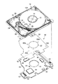
図1および図2に示すように、HDDは、上面の開口した矩形箱状のケース10と、複数のねじによりケースにねじ止めされてケースの上端開口を閉塞する図示しないトップカバーと、を有している。
As shown in FIG. 1 and FIG. 2, the HDD has a rectangular box-
ケース10内には、記録媒体としての2枚の磁気ディスク12a、12b、これらの磁気ディスクを支持および回転させるスピンドルモータ13、磁気ディスクに対して情報の記録、再生を行なう複数の磁気ヘッド、これらの磁気ヘッドを磁気ディスク12a、12bに対して移動自在に支持したヘッドアクチュエータ14、ヘッドアクチュエータを回動および位置決めするボイスコイルモータ(以下VCMと称する)16、磁気ヘッドが磁気ディスクの最外周に移動した際、磁気ヘッドを磁気ディスクから離間した位置に保持するランプロード機構18、ヘッドクチュエータを退避位置に保持するイナーシャラッチ機構20、およびプリアンプ等の回路部品が実装されたフレキシブルプリント回路基板ユニット(以下、FPCユニットと称する)17が収納されている。ケース10は底壁11を有し、スピンドルモータ13、ヘッドアクチュエータ14、VCM16等は底壁11の内面上に設けられている。底壁11の外面ほぼ中央部からは、円柱形状に形成されたスピンドルモータ13のコア部15が突出している。
In the
各磁気ディスク12a、12bは、例えば、直径65mm(2.5インチ)に形成され、上面および下面に磁気記録層を有している。2枚の磁気ディスク12a、12bは、スピンドルモータ13の図示しないハブに互いに同軸的に嵌合されているとともにクランプばね21によりクランプされ、ハブの軸方向に沿って所定の間隔をおいて積層されている。そして、磁気ディスク12a、12bは、駆動部としてのスピンドルモータ13により所定の速度で回転駆動される。
Each of the
ヘッドアクチュエータ14は、ケース10の底壁上に固定された軸受組立体24と、この軸受組立体に取り付けられた4本のアーム27と、各アームに支持された4つの磁気ヘッド組立体30と、を備えている。各磁気ヘッド組立体30は、板ばねによって形成された細長いサスペンション32と、サスペンションに固定された磁気ヘッド33と、を備えている。
The
VCM16は、ヘッドアクチュエータ14に設けられた図示しないボイスコイルと、底壁11上に固定されボイスコイルと対向したヨーク38、およびこのヨークに固定された図示しない磁石とを有している。
The
FPCユニット17は、ケース10の底壁上に固定された矩形状の基板本体34を有し、この基板本体上には、複数の電子部品およびコネクタ等が実装されている。FPCユニット17は、基板本体34とヘッドアクチュエータ14とを電気的に接続した帯状のメインフレキシブルプリント回路基板36を有している。ヘッドアクチュエータ14に支持された各磁気ヘッド33は、アーム27上に設けられた図示しない中継FPCおよびメインフレキシブルプリント回路基板36を介してFPCユニット17に電気的に接続されている。
The
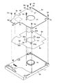
図1ないし図4、および図6に示すように、ケース10の底壁11外面には、FPCユニット17を介してスピンドルモータ13、VCM16、および磁気ヘッドの動作を制御するプリント回路基板(以下、PCBと称する)40がねじ止めされ、ケースの底壁11と対向している。また、ケース10の底壁11外面とPCB40との間には、絶縁シート50が配置されている。
As shown in FIG. 1 to FIG. 4 and FIG. 6, a printed circuit board (hereinafter referred to as “the printed circuit board”) that controls the operations of the
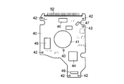
PCB40はケース10の底壁11に対応したほぼ矩形状に形成されている。PCB40のほぼ中央部には、スピンドルモータ13のコア部15を挿通するための円形の開口41が形成されている。PCB40の周縁部には、ねじを通すための複数の透孔42が形成されているとともに、PCBの中央部で開口41の近傍には、ねじを通すための他の透孔43が形成されている。透孔43は、最も離間した2つの透孔42間に位置している。PCB40において、複数の透孔42の部分は、PCB40をケース10の底壁11にねじ止めするための第1ねじ止め部を形成し、透孔43の部分は第2ねじ止め部を形成している。
The PCB 40 is formed in a substantially rectangular shape corresponding to the
PCB40上には多数の電子部品が実装されている。これらの電子部品は、半導体素子として、SOC44、DRAM45、ドライバ46等のLSI、ショックセンサ47、その他、多くのディスクリート部品、チップ部品を含んでいる。比較的面積の大きなSOC44は、PCB40上において、開口41と、この開口41から最も離間したPCB端縁との間に実装されている。ショックセンサ47のPCB40の1つの角部近傍に実装されている。また、PCB40には、FPCユニット17側の第1コネクタ48と接続可能な第2コネクタ49、およびHDDをパーソナルコンピュータ等の電子機器に接続するための主コネクタ52が実装されている。
A large number of electronic components are mounted on the PCB 40. These electronic components include semiconductor elements such as SOC 44,
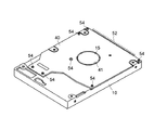
PCB40は、電子部品が実装されている面がケース10の底壁11外面と対向した状態で、かつ、第2コネクタ72を第1コネクタ67に接続した状態で、底壁11外面と対向配置されている。そして、PCB40は、それぞれ透孔42、43に挿通された複数のねじ54により底壁11外面にねじとめ固定されている。PCB40を底壁11外面に取り付けた状態において、スピンドルモータ13のコア部15はPCBの開口41内に位置し、また、PCB全体は、VCM16の下部ヨークが埋め込まれた底壁部分を避けて配置されている。
The PCB 40 is disposed to face the outer surface of the
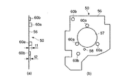
図1ないし図4および図5に示すように、ケース10の底壁11とPCB40との間に設けられた絶縁シート50は、例えば、PET(ポリエチレンテレフタレート)等の絶縁物からなるフィルム状のシート本体56と、このシート本体上に固定された複数の独立したダンピング材とを有している。シート本体56は、PCB40にほぼ対応した大きさおよび形状に形成され、その中央部には、スピンドルモータ13のコア部15を挿通するための円形の開口57が形成されている。開口57の近傍には、ねじを通すための透孔58が形成されている。
As shown in FIGS. 1 to 4 and 5, the
複数のダンピング材は、開口57の周囲に互いに離間して位置した複数、例えば、3つの独立した第1ダンピング材60aを含んでいる。これらの第1ダンピング材60aは円柱形状に形成され、その一端が接着剤によりシート本体56の表面に固定されている。これにより、各第1ダンピング材60aは、シート本体の表面からほぼ垂直に延出している。
The plurality of damping materials include a plurality of, for example, three independent first damping
また、複数のダンピング材は複数の第2ダンピング材60bを含み、その内の1つは、PCB40側のSOC44と対応する位置に設けられ、他の1つはPCB40側のショックセンサ47と対応する位置に設けられている。これらの第2ダンピング材60bは円柱形状に形成され、その一端が接着剤によりシート本体56の表面に固定されている。これにより、各第2ダンピング材60aは、シート本体の表面からほぼ垂直に延出している。
The plurality of damping materials include a plurality of second damping
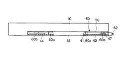
各第2ダンピング材60bの厚さt2は、第1ダンピング材60aの厚さt1よりも小さく形成されている。第1および第2ダンピング材60a、60bは、ウレタン等により形成されている。また、第2ダンピング材60bは、第1ダンピング材60aよりも高い減衰率を有している。
The thickness t2 of each second damping
このように構成された絶縁シート50のシート本体56は、第1および第2ダンピング材60a、60bが設けられている表面側がPCB40と対向した状態で、底壁11外面とPCBとの間に配置され、これら底壁とPCBとの間に挟持されている。シート本体56は、底壁11外面に接触している。スピンドルモータ13のコア部15はシート本体56の開口57内に位置している。このシート本体56は、ケース10の底壁11とPCBとを電気的に絶縁している。
The sheet
3つの第1ダンピング材60aは、コア部15の近傍でコア部の周囲に位置しているとともに、PCB40に当接している。また、第2ダンピング材60bは、SOC44またはショックセンサ47に当接している。なお、PCB40の中央部分、つまり、第2ねじ止め部をねじ止めしたねじ54はシート本体56の透孔58を通って底壁11にねじ込まれ、第1ダンピング材60aの近傍に位置している。
The three first damping
上記のように構成されたHDDによれば、絶縁シート50は互いに独立した複数のダンピング材を有し、3つの第1ダンピング材60aは、振動源となるスピンドルモータ13のコア部15周辺に対向し、このコア部を取り囲むように配置されている。従って、スピンドルモータ13の回転に起因する振動は、第1および第2ダンピング材60a、60bを介してPCB40に伝わり、その際、これらのダンピング材によって効率良く減衰される。従って、PCB40の振動を抑制することができる。
According to the HDD configured as described above, the insulating
また、第2ダンピング材60bは、PCB40上で最も高さの高いSOC44、またはショックセンサ47に接触して設けられている。そのため、電子部品が実装されたPCB40のほとんど全ての領域で、スピンドルモータ13の振動は第2ダンピング材60bで減衰されてPCBに伝達される。従って、PCB40の振動を防止することができる。更に、第2ダンピング材60bにより、ショックセンサ47に伝わる振動が減衰される。これにより、ショックセンサ47は、スピンドルモータ13の振動に起因する検出誤差を防止し、HDD全体に作用する加速度を高い精度で検出することが可能となる。
Further, the second damping
SOC44はLSIであり、外側は樹脂で固められているとともに面積も比較的大きい。そのため、PCB40において、SOC44が実装されている領域は、SOC周囲の電子部品が実装されていない領域に比較して、曲げ剛性が高い。よって第2ダンピング材60bをSOC44とケース底壁との間に配置した場合でも、PCBが反る量を低減することができる。
The
スピンドルモータ13のコア部15周辺部に複数の第1ダンピング材60aが配置されているが、この部分周辺にPCB40とケース底壁とを固定する第2ねじ止め部を少なくとも1つ設けることで、PCBの反りを低減することができる。すなわち、PCB40の周縁部以外の領域では、スピンドルモータ13のコア部周辺の1箇所のみにねじ止め部を設けるだけでPCBの反りを低減することが可能となる。
A plurality of first damping
ショックセンサ47に対向した部分に厚い第2ダンピング材60bが配置されているが、ショックセンサ37はPCB40の周縁部に配置され、このショックセンサの近傍に、PCB40とケース底壁とを固定する第1ねじ止め部が設けられている。そのため、第2ダンピング材60bに起因するPCB40の反りを大幅に低減することができる。
A thick second damping
各ダンピング材はシート本体に接着剤によって貼付されているため、HDD組み立て時に一部のダンピング材のみが横ずれしたり、HDD完成後に横方向の衝撃で一部のダンピング材が横にずれたりすることを防止でき、常に複数のダンピング材によってPCB40の振動抑制効果を得ることができる。
Since each damping material is affixed to the sheet body with an adhesive, only a part of the damping material is laterally displaced when the HDD is assembled, or a part of the damping material is laterally displaced by a lateral impact after the HDD is completed. The vibration suppression effect of the
また、PCB40の基板表面よりも高さの高いSOC44やショックセンサ47に当接した第2ダンピング材60bは、第1ダンピング材60aよりも高さが低く形成されているため、第2ダンピング材の介在に起因するPCB40の反り発生を防止することができる。また、第2ダンピング材60bは、第1ダンピング材60aよりも低いにも拘らず、第1ダンピング材よりも高い減衰力を有しているため、ケース10側から伝わる振動を効率良く減衰することが可能となる。
In addition, the second damping
以上のように、振動抑制効果の大きい厚いダンピング材をケース底壁11とPCB40との間に挿入してPCBの振動を抑えることで、HDDが発する騒音を低下させ、更に、PCB上のショックセンサの衝撃検出精度が向上したHDDおよび絶縁シートを得ることができる。また、第1および第2ダンピング材60a、60bはPCB40上の曲げ剛性の高い部分や、PCBのねじ止め部の周辺のみに配置されるため、ダンピング材に起因したPCBの反りを小さくし、HDD装着時にPCBの飛び出しを防止できる。各ダンピング材はシート本体に接着剤で貼付され一体となっているため、HDD組み立て時に一部のダンピング材のみが横ずれしたり、HDD完成後に横方向の衝撃で一部のダンピング材が横にずれたりすることもなく、常にPCBの振動抑制効果を得ることができる。
As described above, a thick damping material having a large vibration suppressing effect is inserted between the case
なお、本発明は上記実施形態そのままに限定されるものではなく、実施段階ではその要旨を逸脱しない範囲で構成要素を変形して具体化できる。また、上記実施形態に開示されている複数の構成要素の適宜な組み合わせにより、種々の発明を形成できる。例えば、実施形態に示される全構成要素から幾つかの構成要素を削除してもよい。さらに、異なる実施形態にわたる構成要素を適宜組み合わせてもよい。 Note that the present invention is not limited to the above-described embodiment as it is, and can be embodied by modifying the constituent elements without departing from the scope of the invention in the implementation stage. In addition, various inventions can be formed by appropriately combining a plurality of components disclosed in the embodiment. For example, some components may be deleted from all the components shown in the embodiment. Furthermore, constituent elements over different embodiments may be appropriately combined.
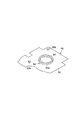
例えば、絶縁シートにおけるダンピング材は、複数個独立して設けられていればよく、その形状は、円柱形状に限らず任意の形状とすることができる。図7に示すように、第1ダンピング材60aは、スピンドルモータ13のコア部15の周囲に沿って延びた環状に形成してもよい。ダンピング材の数は必要に応じて増減可能であるとともに、その材質は必要に応じて種々選択可能である。また、PCB上に電子部品に当接する複数の第2ダンピング材は、互いに同一の厚さである必要はなく、当接する電子部品の厚さに応じて、互いに異なる厚さに形成してもよい。更に、ダンピング材は、シート本体のPCBと対向する表面に設ける構成としたが、シート本体の他方の表面上、あるいは両方の表面上に設けてもよい。
For example, the damping material in an insulating sheet should just be provided independently, and the shape can be made into arbitrary shapes not only in a cylindrical shape. As shown in FIG. 7, the first damping
HDDにおいて、磁気ディスクの枚数は1枚に限らず、必要に応じて増加可能である。この発明は、磁気ディスク装置に限らず、光ディスク装置等の他のディスク装置にも適用することができる。 In the HDD, the number of magnetic disks is not limited to one, and can be increased as necessary. The present invention can be applied not only to the magnetic disk device but also to other disk devices such as an optical disk device.
10…ベース、 11…底壁、 12a、12b…磁気ディスク、
13…スピンドルモータ、 40…PCB、 44…SOC、
42、43…透孔、 47…ショックセンサ、 50…絶縁シート、
56…シート本体、 60a…第1ダンピング材、 60b…第2ダンピング材。
10 ... Base, 11 ... Bottom wall, 12a, 12b ... Magnetic disk,
13 ... Spindle motor, 40 ... PCB, 44 ... SOC,
42, 43 ... through hole, 47 ... shock sensor, 50 ... insulating sheet,
56 ... sheet main body, 60a ... first damping material, 60b ... second damping material.
Claims (13)
絶縁物で形成され前記底壁の外面と対向して配置されたシート本体と、
前記シート本体上にそれぞれ独立して設けられた複数のダンピング材と、を備え、
前記ダンピング材は、前記モータの近傍に位置し前記プリント回路基板に当接した第1ダンピング材と、
前記プリント回路基板上の電子部品に当接した第2ダンピング材とを含んでいる絶縁シート。 A case having a bottom wall; a disc-shaped recording medium provided in the case; a motor provided on the bottom wall for holding and rotating the recording medium; and a plurality of electronic components mounted thereon. In the insulating sheet used for the disk device provided with a printed circuit board provided to face the outer surface of the bottom wall,
A sheet body formed of an insulator and disposed opposite the outer surface of the bottom wall;
A plurality of damping materials provided independently on the seat body, and
The damping material is a first damping material located in the vicinity of the motor and in contact with the printed circuit board;
An insulating sheet including a second damping material in contact with an electronic component on the printed circuit board.
前記ケース内に設けられたディスク状の記録媒体と、
前記底壁に設けられ前記記録媒体を保持および回転するモータと、
複数の電子部品が実装されているとともに前記底壁の外面に対向して取り付けられたプリント回路基板と、
前記底壁の外面とプリント回路基板との間に設けられた絶縁シートと、を備え、
前記絶縁シートは、絶縁物で形成され前記底壁の外面と対向して配置されたシート本体と、前記シート本体上にそれぞれ独立して設けられた複数のダンピング材と、を有し、前記ダンピング材は、前記モータの近傍に位置し前記プリント回路基板に当接した第1ダンピング材と、前記プリント回路基板上の電子部品に当接した第2ダンピング材とを含んでいるディスク装置。 A case with a bottom wall;
A disc-shaped recording medium provided in the case;
A motor provided on the bottom wall for holding and rotating the recording medium;
A printed circuit board on which a plurality of electronic components are mounted and attached facing the outer surface of the bottom wall;
An insulating sheet provided between the outer surface of the bottom wall and the printed circuit board,
The insulating sheet includes a sheet main body formed of an insulating material and disposed opposite to the outer surface of the bottom wall, and a plurality of damping materials provided independently on the sheet main body, and the damping The disk device includes: a first damping material positioned near the motor and contacting the printed circuit board; and a second damping material contacting the electronic component on the printed circuit board.
Priority Applications (4)
| Application Number | Priority Date | Filing Date | Title |
|---|---|---|---|
| JP2004107343A JP2005293717A (en) | 2004-03-31 | 2004-03-31 | Insulating sheet and disk device provided with the same |
| SG200502288A SG115835A1 (en) | 2004-03-31 | 2005-03-07 | Insulation sheet and disk device provided with the same |
| US11/082,034 US20050219738A1 (en) | 2004-03-31 | 2005-03-17 | Insulation sheet and disk device provided with the same |
| CNA2005100595836A CN1677552A (en) | 2004-03-31 | 2005-03-30 | Insulation sheet and disk device provided with the same |
Applications Claiming Priority (1)
| Application Number | Priority Date | Filing Date | Title |
|---|---|---|---|
| JP2004107343A JP2005293717A (en) | 2004-03-31 | 2004-03-31 | Insulating sheet and disk device provided with the same |
Publications (1)
| Publication Number | Publication Date |
|---|---|
| JP2005293717A true JP2005293717A (en) | 2005-10-20 |
Family
ID=35049997
Family Applications (1)
| Application Number | Title | Priority Date | Filing Date |
|---|---|---|---|
| JP2004107343A Pending JP2005293717A (en) | 2004-03-31 | 2004-03-31 | Insulating sheet and disk device provided with the same |
Country Status (4)
| Country | Link |
|---|---|
| US (1) | US20050219738A1 (en) |
| JP (1) | JP2005293717A (en) |
| CN (1) | CN1677552A (en) |
| SG (1) | SG115835A1 (en) |
Cited By (2)
| Publication number | Priority date | Publication date | Assignee | Title |
|---|---|---|---|---|
| US8885292B1 (en) | 2014-01-28 | 2014-11-11 | Kabushiki Kaisha Toshiba | Insulating member and disk device with the same |
| KR20160126746A (en) * | 2015-04-24 | 2016-11-02 | 시게이트 테크놀로지 엘엘씨 | Printed circuit board, and data storage device and electronic apparatus comprising the same |
Families Citing this family (6)
| Publication number | Priority date | Publication date | Assignee | Title |
|---|---|---|---|---|
| JP2005063577A (en) * | 2003-08-15 | 2005-03-10 | Hitachi Global Storage Technologies Netherlands Bv | Rotating disk storage device |
| JP2006294170A (en) * | 2005-04-13 | 2006-10-26 | Toshiba Corp | Disk unit |
| KR100665025B1 (en) * | 2005-07-18 | 2007-01-09 | 삼성전자주식회사 | Assembly and Shock Absorber for Installation of Disk Drives |
| US7786388B2 (en) * | 2007-10-24 | 2010-08-31 | Hitachi Global Storage Technologies Netherlands B.V. | Card insulator with provision for conformance to component height changes |
| US20100259852A1 (en) * | 2009-04-14 | 2010-10-14 | Purpose SAE Magnetics (HK) Ltd. | Hard disc drive assembly with PCB with IO and read/write connectors on the same end |
| US9318930B2 (en) * | 2013-08-13 | 2016-04-19 | Seagate Technology Llc | Component configured to stiffen an electric motor assembly |
Family Cites Families (16)
| Publication number | Priority date | Publication date | Assignee | Title |
|---|---|---|---|---|
| US5235482A (en) * | 1989-11-09 | 1993-08-10 | Rodime Plc | Magnetic disk drive incorporating a mechanically damped base |
| KR0124990B1 (en) * | 1993-12-01 | 1997-11-28 | 김광호 | Support device for mitigating vibration noise and external impact in a hard disk drive |
| US5757580A (en) * | 1996-11-27 | 1998-05-26 | Seagate Technology, Inc. | Constrain layer damping of a disc drive printed wiring assembly |
| US5958556A (en) * | 1996-12-19 | 1999-09-28 | Minnesota Mining And Manufacturing Company | Vibration damped and stiffened circuit articles |
| US6674608B1 (en) * | 1999-05-07 | 2004-01-06 | Seagate Technologies Llc | Damped protective cover to improve disc drive acoustics |
| US6735043B2 (en) * | 1999-05-07 | 2004-05-11 | Seagate Technology Llc | Disc drive protective cover to improve shock robustness |
| US6288866B1 (en) * | 1999-11-19 | 2001-09-11 | Western Digital Technologies, Inc. | Disk drive including a vibration damping system having a compressible foam and mass damper fixed adjacent to the outer surface of a printed circuit board for reducing noise and vibration |
| KR100396546B1 (en) * | 2000-12-21 | 2003-09-02 | 삼성전자주식회사 | Disk player, and turntable incorporating self-compensating dynamic balancer, clamper incorporating self-compensating dynamic balancer and spindle motor incorporating self compensating dynamic balancer adopted for disk player |
| US6672575B2 (en) * | 2001-06-12 | 2004-01-06 | Lord Corporation | Surface effect damper |
| US6961219B2 (en) * | 2001-08-31 | 2005-11-01 | 3M Innovative Properties Company | Disk drive head positioner with thin-film air-flow adjusting mechanism, thin film member and method of manufacturing |
| US6898051B2 (en) * | 2001-11-27 | 2005-05-24 | Seagate Technology Llc | Disc drive spindle motor having a damper on a bottom surface of the spindle motor |
| US6697217B1 (en) * | 2001-11-30 | 2004-02-24 | Western Digital Technologies, Inc. | Disk drive comprising a coating bonded to a printed circuit board assembly |
| US6969239B2 (en) * | 2002-09-30 | 2005-11-29 | General Electric Company | Apparatus and method for damping vibrations between a compressor stator vane and a casing of a gas turbine engine |
| DE10308095B3 (en) * | 2003-02-24 | 2004-10-14 | Infineon Technologies Ag | Electronic component with at least one semiconductor chip on a circuit carrier and method for producing the same |
| US6958884B1 (en) * | 2003-05-30 | 2005-10-25 | Western Digital Technologies, Inc. | Disk drive having an acoustic damping shield assembly with an acoustic barrier layer |
| KR100532461B1 (en) * | 2003-08-21 | 2005-12-01 | 삼성전자주식회사 | Disk drive having heat sinking apparatus |
-
2004
- 2004-03-31 JP JP2004107343A patent/JP2005293717A/en active Pending
-
2005
- 2005-03-07 SG SG200502288A patent/SG115835A1/en unknown
- 2005-03-17 US US11/082,034 patent/US20050219738A1/en not_active Abandoned
- 2005-03-30 CN CNA2005100595836A patent/CN1677552A/en active Pending
Cited By (3)
| Publication number | Priority date | Publication date | Assignee | Title |
|---|---|---|---|---|
| US8885292B1 (en) | 2014-01-28 | 2014-11-11 | Kabushiki Kaisha Toshiba | Insulating member and disk device with the same |
| KR20160126746A (en) * | 2015-04-24 | 2016-11-02 | 시게이트 테크놀로지 엘엘씨 | Printed circuit board, and data storage device and electronic apparatus comprising the same |
| KR102301649B1 (en) * | 2015-04-24 | 2021-09-10 | 시게이트 테크놀로지 엘엘씨 | Printed circuit board, and data storage device and electronic apparatus comprising the same |
Also Published As
| Publication number | Publication date |
|---|---|
| SG115835A1 (en) | 2005-10-28 |
| US20050219738A1 (en) | 2005-10-06 |
| CN1677552A (en) | 2005-10-05 |
Similar Documents
| Publication | Publication Date | Title |
|---|---|---|
| US8432641B1 (en) | Disk drive with multi-zone arm damper | |
| US8345387B1 (en) | Disk drive with transverse plane damper | |
| JP4886882B2 (en) | Head stack assembly and disk drive device having the same | |
| US11527262B2 (en) | Disk device having a multi-actuator assembly with a protective member attached to the tip of an actuator arm | |
| CN101159153A (en) | disk device | |
| US7889459B2 (en) | HDD and HDD stack assembly with head suspension having multiple combination parts and spacer | |
| JP2008287769A (en) | Disk unit | |
| JP2003173639A (en) | Recording and playback device | |
| JP2005293717A (en) | Insulating sheet and disk device provided with the same | |
| CN111653293B (en) | Disk device | |
| US7667926B2 (en) | Disk device | |
| JP2019169213A (en) | Disk device and assembly method of disk device | |
| JP2000076811A (en) | Magnetic disk drive | |
| JP4908615B2 (en) | Head suspension assembly and disk drive equipped with the same | |
| US7336447B2 (en) | Disk device with inertia arm retaining portion stepped up from top yoke | |
| JP3788865B2 (en) | Magnetic disk unit | |
| US20250336414A1 (en) | Disk device | |
| JP2012014794A (en) | Head gimbal assembly and disk device provided with the same | |
| JP4234634B2 (en) | Magnetic disk unit | |
| JP3464992B2 (en) | Disk unit | |
| JP4435247B2 (en) | Head stack assembly and disk drive device having the same | |
| JP2011123953A (en) | Disk device | |
| JPH11345474A (en) | Magnetic disk drive | |
| JP4309454B2 (en) | Head stack assembly and disk drive device having the same | |
| JP2003085938A (en) | Magnetic disk drive |