JP2008274254A - Phosphor, method for producing the same, phosphor-containing composition, light-emitting device, image display device, and illuminating device - Google Patents
Phosphor, method for producing the same, phosphor-containing composition, light-emitting device, image display device, and illuminating device Download PDFInfo
- Publication number
- JP2008274254A JP2008274254A JP2008091914A JP2008091914A JP2008274254A JP 2008274254 A JP2008274254 A JP 2008274254A JP 2008091914 A JP2008091914 A JP 2008091914A JP 2008091914 A JP2008091914 A JP 2008091914A JP 2008274254 A JP2008274254 A JP 2008274254A
- Authority
- JP
- Japan
- Prior art keywords
- phosphor
- light
- less
- emitting device
- emission
- Prior art date
- Legal status (The legal status is an assumption and is not a legal conclusion. Google has not performed a legal analysis and makes no representation as to the accuracy of the status listed.)
- Pending
Links
Images


Classifications
-
- C—CHEMISTRY; METALLURGY
- C09—DYES; PAINTS; POLISHES; NATURAL RESINS; ADHESIVES; COMPOSITIONS NOT OTHERWISE PROVIDED FOR; APPLICATIONS OF MATERIALS NOT OTHERWISE PROVIDED FOR
- C09K—MATERIALS FOR MISCELLANEOUS APPLICATIONS, NOT PROVIDED FOR ELSEWHERE
- C09K11/00—Luminescent, e.g. electroluminescent, chemiluminescent materials
- C09K11/08—Luminescent, e.g. electroluminescent, chemiluminescent materials containing inorganic luminescent materials
- C09K11/77—Luminescent, e.g. electroluminescent, chemiluminescent materials containing inorganic luminescent materials containing rare earth metals
- C09K11/7728—Luminescent, e.g. electroluminescent, chemiluminescent materials containing inorganic luminescent materials containing rare earth metals containing europium
- C09K11/7734—Aluminates
-
- C—CHEMISTRY; METALLURGY
- C04—CEMENTS; CONCRETE; ARTIFICIAL STONE; CERAMICS; REFRACTORIES
- C04B—LIME, MAGNESIA; SLAG; CEMENTS; COMPOSITIONS THEREOF, e.g. MORTARS, CONCRETE OR LIKE BUILDING MATERIALS; ARTIFICIAL STONE; CERAMICS; REFRACTORIES; TREATMENT OF NATURAL STONE
- C04B35/00—Shaped ceramic products characterised by their composition; Ceramics compositions; Processing powders of inorganic compounds preparatory to the manufacturing of ceramic products
- C04B35/01—Shaped ceramic products characterised by their composition; Ceramics compositions; Processing powders of inorganic compounds preparatory to the manufacturing of ceramic products based on oxide ceramics
- C04B35/16—Shaped ceramic products characterised by their composition; Ceramics compositions; Processing powders of inorganic compounds preparatory to the manufacturing of ceramic products based on oxide ceramics based on silicates other than clay
-
- C—CHEMISTRY; METALLURGY
- C04—CEMENTS; CONCRETE; ARTIFICIAL STONE; CERAMICS; REFRACTORIES
- C04B—LIME, MAGNESIA; SLAG; CEMENTS; COMPOSITIONS THEREOF, e.g. MORTARS, CONCRETE OR LIKE BUILDING MATERIALS; ARTIFICIAL STONE; CERAMICS; REFRACTORIES; TREATMENT OF NATURAL STONE
- C04B35/00—Shaped ceramic products characterised by their composition; Ceramics compositions; Processing powders of inorganic compounds preparatory to the manufacturing of ceramic products
- C04B35/01—Shaped ceramic products characterised by their composition; Ceramics compositions; Processing powders of inorganic compounds preparatory to the manufacturing of ceramic products based on oxide ceramics
- C04B35/44—Shaped ceramic products characterised by their composition; Ceramics compositions; Processing powders of inorganic compounds preparatory to the manufacturing of ceramic products based on oxide ceramics based on aluminates
-
- C—CHEMISTRY; METALLURGY
- C04—CEMENTS; CONCRETE; ARTIFICIAL STONE; CERAMICS; REFRACTORIES
- C04B—LIME, MAGNESIA; SLAG; CEMENTS; COMPOSITIONS THEREOF, e.g. MORTARS, CONCRETE OR LIKE BUILDING MATERIALS; ARTIFICIAL STONE; CERAMICS; REFRACTORIES; TREATMENT OF NATURAL STONE
- C04B35/00—Shaped ceramic products characterised by their composition; Ceramics compositions; Processing powders of inorganic compounds preparatory to the manufacturing of ceramic products
- C04B35/515—Shaped ceramic products characterised by their composition; Ceramics compositions; Processing powders of inorganic compounds preparatory to the manufacturing of ceramic products based on non-oxide ceramics
- C04B35/58—Shaped ceramic products characterised by their composition; Ceramics compositions; Processing powders of inorganic compounds preparatory to the manufacturing of ceramic products based on non-oxide ceramics based on borides, nitrides, i.e. nitrides, oxynitrides, carbonitrides or oxycarbonitrides or silicides
- C04B35/581—Shaped ceramic products characterised by their composition; Ceramics compositions; Processing powders of inorganic compounds preparatory to the manufacturing of ceramic products based on non-oxide ceramics based on borides, nitrides, i.e. nitrides, oxynitrides, carbonitrides or oxycarbonitrides or silicides based on aluminium nitride
-
- C—CHEMISTRY; METALLURGY
- C04—CEMENTS; CONCRETE; ARTIFICIAL STONE; CERAMICS; REFRACTORIES
- C04B—LIME, MAGNESIA; SLAG; CEMENTS; COMPOSITIONS THEREOF, e.g. MORTARS, CONCRETE OR LIKE BUILDING MATERIALS; ARTIFICIAL STONE; CERAMICS; REFRACTORIES; TREATMENT OF NATURAL STONE
- C04B35/00—Shaped ceramic products characterised by their composition; Ceramics compositions; Processing powders of inorganic compounds preparatory to the manufacturing of ceramic products
- C04B35/515—Shaped ceramic products characterised by their composition; Ceramics compositions; Processing powders of inorganic compounds preparatory to the manufacturing of ceramic products based on non-oxide ceramics
- C04B35/58—Shaped ceramic products characterised by their composition; Ceramics compositions; Processing powders of inorganic compounds preparatory to the manufacturing of ceramic products based on non-oxide ceramics based on borides, nitrides, i.e. nitrides, oxynitrides, carbonitrides or oxycarbonitrides or silicides
- C04B35/584—Shaped ceramic products characterised by their composition; Ceramics compositions; Processing powders of inorganic compounds preparatory to the manufacturing of ceramic products based on non-oxide ceramics based on borides, nitrides, i.e. nitrides, oxynitrides, carbonitrides or oxycarbonitrides or silicides based on silicon nitride
-
- C—CHEMISTRY; METALLURGY
- C04—CEMENTS; CONCRETE; ARTIFICIAL STONE; CERAMICS; REFRACTORIES
- C04B—LIME, MAGNESIA; SLAG; CEMENTS; COMPOSITIONS THEREOF, e.g. MORTARS, CONCRETE OR LIKE BUILDING MATERIALS; ARTIFICIAL STONE; CERAMICS; REFRACTORIES; TREATMENT OF NATURAL STONE
- C04B35/00—Shaped ceramic products characterised by their composition; Ceramics compositions; Processing powders of inorganic compounds preparatory to the manufacturing of ceramic products
- C04B35/515—Shaped ceramic products characterised by their composition; Ceramics compositions; Processing powders of inorganic compounds preparatory to the manufacturing of ceramic products based on non-oxide ceramics
- C04B35/58—Shaped ceramic products characterised by their composition; Ceramics compositions; Processing powders of inorganic compounds preparatory to the manufacturing of ceramic products based on non-oxide ceramics based on borides, nitrides, i.e. nitrides, oxynitrides, carbonitrides or oxycarbonitrides or silicides
- C04B35/597—Shaped ceramic products characterised by their composition; Ceramics compositions; Processing powders of inorganic compounds preparatory to the manufacturing of ceramic products based on non-oxide ceramics based on borides, nitrides, i.e. nitrides, oxynitrides, carbonitrides or oxycarbonitrides or silicides based on silicon oxynitride, e.g. SIALONS
-
- C—CHEMISTRY; METALLURGY
- C04—CEMENTS; CONCRETE; ARTIFICIAL STONE; CERAMICS; REFRACTORIES
- C04B—LIME, MAGNESIA; SLAG; CEMENTS; COMPOSITIONS THEREOF, e.g. MORTARS, CONCRETE OR LIKE BUILDING MATERIALS; ARTIFICIAL STONE; CERAMICS; REFRACTORIES; TREATMENT OF NATURAL STONE
- C04B35/00—Shaped ceramic products characterised by their composition; Ceramics compositions; Processing powders of inorganic compounds preparatory to the manufacturing of ceramic products
- C04B35/622—Forming processes; Processing powders of inorganic compounds preparatory to the manufacturing of ceramic products
- C04B35/626—Preparing or treating the powders individually or as batches ; preparing or treating macroscopic reinforcing agents for ceramic products, e.g. fibres; mechanical aspects section B
- C04B35/62605—Treating the starting powders individually or as mixtures
- C04B35/6261—Milling
- C04B35/6262—Milling of calcined, sintered clinker or ceramics
-
- H—ELECTRICITY
- H01—ELECTRIC ELEMENTS
- H01S—DEVICES USING THE PROCESS OF LIGHT AMPLIFICATION BY STIMULATED EMISSION OF RADIATION [LASER] TO AMPLIFY OR GENERATE LIGHT; DEVICES USING STIMULATED EMISSION OF ELECTROMAGNETIC RADIATION IN WAVE RANGES OTHER THAN OPTICAL
- H01S5/00—Semiconductor lasers
- H01S5/005—Optical components external to the laser cavity, specially adapted therefor, e.g. for homogenisation or merging of the beams or for manipulating laser pulses, e.g. pulse shaping
- H01S5/0087—Optical components external to the laser cavity, specially adapted therefor, e.g. for homogenisation or merging of the beams or for manipulating laser pulses, e.g. pulse shaping for illuminating phosphorescent or fluorescent materials, e.g. using optical arrangements specifically adapted for guiding or shaping laser beams illuminating these materials
-
- H—ELECTRICITY
- H01—ELECTRIC ELEMENTS
- H01S—DEVICES USING THE PROCESS OF LIGHT AMPLIFICATION BY STIMULATED EMISSION OF RADIATION [LASER] TO AMPLIFY OR GENERATE LIGHT; DEVICES USING STIMULATED EMISSION OF ELECTROMAGNETIC RADIATION IN WAVE RANGES OTHER THAN OPTICAL
- H01S5/00—Semiconductor lasers
- H01S5/10—Construction or shape of the optical resonator, e.g. extended or external cavity, coupled cavities, bent-guide, varying width, thickness or composition of the active region
- H01S5/18—Surface-emitting [SE] lasers, e.g. having both horizontal and vertical cavities
- H01S5/183—Surface-emitting [SE] lasers, e.g. having both horizontal and vertical cavities having only vertical cavities, e.g. vertical cavity surface-emitting lasers [VCSEL]
- H01S5/18386—Details of the emission surface for influencing the near- or far-field, e.g. a grating on the surface
-
- C—CHEMISTRY; METALLURGY
- C04—CEMENTS; CONCRETE; ARTIFICIAL STONE; CERAMICS; REFRACTORIES
- C04B—LIME, MAGNESIA; SLAG; CEMENTS; COMPOSITIONS THEREOF, e.g. MORTARS, CONCRETE OR LIKE BUILDING MATERIALS; ARTIFICIAL STONE; CERAMICS; REFRACTORIES; TREATMENT OF NATURAL STONE
- C04B2235/00—Aspects relating to ceramic starting mixtures or sintered ceramic products
- C04B2235/02—Composition of constituents of the starting material or of secondary phases of the final product
- C04B2235/30—Constituents and secondary phases not being of a fibrous nature
- C04B2235/32—Metal oxides, mixed metal oxides, or oxide-forming salts thereof, e.g. carbonates, nitrates, (oxy)hydroxides, chlorides
- C04B2235/3205—Alkaline earth oxides or oxide forming salts thereof, e.g. beryllium oxide
- C04B2235/3206—Magnesium oxides or oxide-forming salts thereof
-
- C—CHEMISTRY; METALLURGY
- C04—CEMENTS; CONCRETE; ARTIFICIAL STONE; CERAMICS; REFRACTORIES
- C04B—LIME, MAGNESIA; SLAG; CEMENTS; COMPOSITIONS THEREOF, e.g. MORTARS, CONCRETE OR LIKE BUILDING MATERIALS; ARTIFICIAL STONE; CERAMICS; REFRACTORIES; TREATMENT OF NATURAL STONE
- C04B2235/00—Aspects relating to ceramic starting mixtures or sintered ceramic products
- C04B2235/02—Composition of constituents of the starting material or of secondary phases of the final product
- C04B2235/30—Constituents and secondary phases not being of a fibrous nature
- C04B2235/32—Metal oxides, mixed metal oxides, or oxide-forming salts thereof, e.g. carbonates, nitrates, (oxy)hydroxides, chlorides
- C04B2235/3205—Alkaline earth oxides or oxide forming salts thereof, e.g. beryllium oxide
- C04B2235/3213—Strontium oxides or oxide-forming salts thereof
-
- C—CHEMISTRY; METALLURGY
- C04—CEMENTS; CONCRETE; ARTIFICIAL STONE; CERAMICS; REFRACTORIES
- C04B—LIME, MAGNESIA; SLAG; CEMENTS; COMPOSITIONS THEREOF, e.g. MORTARS, CONCRETE OR LIKE BUILDING MATERIALS; ARTIFICIAL STONE; CERAMICS; REFRACTORIES; TREATMENT OF NATURAL STONE
- C04B2235/00—Aspects relating to ceramic starting mixtures or sintered ceramic products
- C04B2235/02—Composition of constituents of the starting material or of secondary phases of the final product
- C04B2235/30—Constituents and secondary phases not being of a fibrous nature
- C04B2235/32—Metal oxides, mixed metal oxides, or oxide-forming salts thereof, e.g. carbonates, nitrates, (oxy)hydroxides, chlorides
- C04B2235/3205—Alkaline earth oxides or oxide forming salts thereof, e.g. beryllium oxide
- C04B2235/3215—Barium oxides or oxide-forming salts thereof
-
- C—CHEMISTRY; METALLURGY
- C04—CEMENTS; CONCRETE; ARTIFICIAL STONE; CERAMICS; REFRACTORIES
- C04B—LIME, MAGNESIA; SLAG; CEMENTS; COMPOSITIONS THEREOF, e.g. MORTARS, CONCRETE OR LIKE BUILDING MATERIALS; ARTIFICIAL STONE; CERAMICS; REFRACTORIES; TREATMENT OF NATURAL STONE
- C04B2235/00—Aspects relating to ceramic starting mixtures or sintered ceramic products
- C04B2235/02—Composition of constituents of the starting material or of secondary phases of the final product
- C04B2235/30—Constituents and secondary phases not being of a fibrous nature
- C04B2235/32—Metal oxides, mixed metal oxides, or oxide-forming salts thereof, e.g. carbonates, nitrates, (oxy)hydroxides, chlorides
- C04B2235/3217—Aluminum oxide or oxide forming salts thereof, e.g. bauxite, alpha-alumina
-
- C—CHEMISTRY; METALLURGY
- C04—CEMENTS; CONCRETE; ARTIFICIAL STONE; CERAMICS; REFRACTORIES
- C04B—LIME, MAGNESIA; SLAG; CEMENTS; COMPOSITIONS THEREOF, e.g. MORTARS, CONCRETE OR LIKE BUILDING MATERIALS; ARTIFICIAL STONE; CERAMICS; REFRACTORIES; TREATMENT OF NATURAL STONE
- C04B2235/00—Aspects relating to ceramic starting mixtures or sintered ceramic products
- C04B2235/02—Composition of constituents of the starting material or of secondary phases of the final product
- C04B2235/30—Constituents and secondary phases not being of a fibrous nature
- C04B2235/32—Metal oxides, mixed metal oxides, or oxide-forming salts thereof, e.g. carbonates, nitrates, (oxy)hydroxides, chlorides
- C04B2235/3224—Rare earth oxide or oxide forming salts thereof, e.g. scandium oxide
-
- C—CHEMISTRY; METALLURGY
- C04—CEMENTS; CONCRETE; ARTIFICIAL STONE; CERAMICS; REFRACTORIES
- C04B—LIME, MAGNESIA; SLAG; CEMENTS; COMPOSITIONS THEREOF, e.g. MORTARS, CONCRETE OR LIKE BUILDING MATERIALS; ARTIFICIAL STONE; CERAMICS; REFRACTORIES; TREATMENT OF NATURAL STONE
- C04B2235/00—Aspects relating to ceramic starting mixtures or sintered ceramic products
- C04B2235/02—Composition of constituents of the starting material or of secondary phases of the final product
- C04B2235/30—Constituents and secondary phases not being of a fibrous nature
- C04B2235/32—Metal oxides, mixed metal oxides, or oxide-forming salts thereof, e.g. carbonates, nitrates, (oxy)hydroxides, chlorides
- C04B2235/3262—Manganese oxides, manganates, rhenium oxides or oxide-forming salts thereof, e.g. MnO
-
- C—CHEMISTRY; METALLURGY
- C04—CEMENTS; CONCRETE; ARTIFICIAL STONE; CERAMICS; REFRACTORIES
- C04B—LIME, MAGNESIA; SLAG; CEMENTS; COMPOSITIONS THEREOF, e.g. MORTARS, CONCRETE OR LIKE BUILDING MATERIALS; ARTIFICIAL STONE; CERAMICS; REFRACTORIES; TREATMENT OF NATURAL STONE
- C04B2235/00—Aspects relating to ceramic starting mixtures or sintered ceramic products
- C04B2235/02—Composition of constituents of the starting material or of secondary phases of the final product
- C04B2235/30—Constituents and secondary phases not being of a fibrous nature
- C04B2235/38—Non-oxide ceramic constituents or additives
- C04B2235/3852—Nitrides, e.g. oxynitrides, carbonitrides, oxycarbonitrides, lithium nitride, magnesium nitride
- C04B2235/3865—Aluminium nitrides
-
- C—CHEMISTRY; METALLURGY
- C04—CEMENTS; CONCRETE; ARTIFICIAL STONE; CERAMICS; REFRACTORIES
- C04B—LIME, MAGNESIA; SLAG; CEMENTS; COMPOSITIONS THEREOF, e.g. MORTARS, CONCRETE OR LIKE BUILDING MATERIALS; ARTIFICIAL STONE; CERAMICS; REFRACTORIES; TREATMENT OF NATURAL STONE
- C04B2235/00—Aspects relating to ceramic starting mixtures or sintered ceramic products
- C04B2235/02—Composition of constituents of the starting material or of secondary phases of the final product
- C04B2235/30—Constituents and secondary phases not being of a fibrous nature
- C04B2235/38—Non-oxide ceramic constituents or additives
- C04B2235/3852—Nitrides, e.g. oxynitrides, carbonitrides, oxycarbonitrides, lithium nitride, magnesium nitride
- C04B2235/3873—Silicon nitrides, e.g. silicon carbonitride, silicon oxynitride
-
- C—CHEMISTRY; METALLURGY
- C04—CEMENTS; CONCRETE; ARTIFICIAL STONE; CERAMICS; REFRACTORIES
- C04B—LIME, MAGNESIA; SLAG; CEMENTS; COMPOSITIONS THEREOF, e.g. MORTARS, CONCRETE OR LIKE BUILDING MATERIALS; ARTIFICIAL STONE; CERAMICS; REFRACTORIES; TREATMENT OF NATURAL STONE
- C04B2235/00—Aspects relating to ceramic starting mixtures or sintered ceramic products
- C04B2235/02—Composition of constituents of the starting material or of secondary phases of the final product
- C04B2235/30—Constituents and secondary phases not being of a fibrous nature
- C04B2235/44—Metal salt constituents or additives chosen for the nature of the anions, e.g. hydrides or acetylacetonate
- C04B2235/444—Halide containing anions, e.g. bromide, iodate, chlorite
- C04B2235/445—Fluoride containing anions, e.g. fluosilicate
-
- H—ELECTRICITY
- H01—ELECTRIC ELEMENTS
- H01L—SEMICONDUCTOR DEVICES NOT COVERED BY CLASS H10
- H01L2224/00—Indexing scheme for arrangements for connecting or disconnecting semiconductor or solid-state bodies and methods related thereto as covered by H01L24/00
- H01L2224/01—Means for bonding being attached to, or being formed on, the surface to be connected, e.g. chip-to-package, die-attach, "first-level" interconnects; Manufacturing methods related thereto
- H01L2224/42—Wire connectors; Manufacturing methods related thereto
- H01L2224/44—Structure, shape, material or disposition of the wire connectors prior to the connecting process
- H01L2224/45—Structure, shape, material or disposition of the wire connectors prior to the connecting process of an individual wire connector
- H01L2224/45001—Core members of the connector
- H01L2224/4501—Shape
- H01L2224/45012—Cross-sectional shape
- H01L2224/45015—Cross-sectional shape being circular
-
- H—ELECTRICITY
- H01—ELECTRIC ELEMENTS
- H01L—SEMICONDUCTOR DEVICES NOT COVERED BY CLASS H10
- H01L2224/00—Indexing scheme for arrangements for connecting or disconnecting semiconductor or solid-state bodies and methods related thereto as covered by H01L24/00
- H01L2224/01—Means for bonding being attached to, or being formed on, the surface to be connected, e.g. chip-to-package, die-attach, "first-level" interconnects; Manufacturing methods related thereto
- H01L2224/42—Wire connectors; Manufacturing methods related thereto
- H01L2224/44—Structure, shape, material or disposition of the wire connectors prior to the connecting process
- H01L2224/45—Structure, shape, material or disposition of the wire connectors prior to the connecting process of an individual wire connector
- H01L2224/45001—Core members of the connector
- H01L2224/45099—Material
- H01L2224/451—Material with a principal constituent of the material being a metal or a metalloid, e.g. boron (B), silicon (Si), germanium (Ge), arsenic (As), antimony (Sb), tellurium (Te) and polonium (Po), and alloys thereof
- H01L2224/45138—Material with a principal constituent of the material being a metal or a metalloid, e.g. boron (B), silicon (Si), germanium (Ge), arsenic (As), antimony (Sb), tellurium (Te) and polonium (Po), and alloys thereof the principal constituent melting at a temperature of greater than or equal to 950°C and less than 1550°C
- H01L2224/45144—Gold (Au) as principal constituent
-
- H—ELECTRICITY
- H01—ELECTRIC ELEMENTS
- H01L—SEMICONDUCTOR DEVICES NOT COVERED BY CLASS H10
- H01L2224/00—Indexing scheme for arrangements for connecting or disconnecting semiconductor or solid-state bodies and methods related thereto as covered by H01L24/00
- H01L2224/01—Means for bonding being attached to, or being formed on, the surface to be connected, e.g. chip-to-package, die-attach, "first-level" interconnects; Manufacturing methods related thereto
- H01L2224/42—Wire connectors; Manufacturing methods related thereto
- H01L2224/47—Structure, shape, material or disposition of the wire connectors after the connecting process
- H01L2224/48—Structure, shape, material or disposition of the wire connectors after the connecting process of an individual wire connector
- H01L2224/4805—Shape
- H01L2224/4809—Loop shape
- H01L2224/48091—Arched
-
- H—ELECTRICITY
- H01—ELECTRIC ELEMENTS
- H01L—SEMICONDUCTOR DEVICES NOT COVERED BY CLASS H10
- H01L2224/00—Indexing scheme for arrangements for connecting or disconnecting semiconductor or solid-state bodies and methods related thereto as covered by H01L24/00
- H01L2224/01—Means for bonding being attached to, or being formed on, the surface to be connected, e.g. chip-to-package, die-attach, "first-level" interconnects; Manufacturing methods related thereto
- H01L2224/42—Wire connectors; Manufacturing methods related thereto
- H01L2224/47—Structure, shape, material or disposition of the wire connectors after the connecting process
- H01L2224/48—Structure, shape, material or disposition of the wire connectors after the connecting process of an individual wire connector
- H01L2224/481—Disposition
- H01L2224/48151—Connecting between a semiconductor or solid-state body and an item not being a semiconductor or solid-state body, e.g. chip-to-substrate, chip-to-passive
- H01L2224/48221—Connecting between a semiconductor or solid-state body and an item not being a semiconductor or solid-state body, e.g. chip-to-substrate, chip-to-passive the body and the item being stacked
- H01L2224/48245—Connecting between a semiconductor or solid-state body and an item not being a semiconductor or solid-state body, e.g. chip-to-substrate, chip-to-passive the body and the item being stacked the item being metallic
- H01L2224/48247—Connecting between a semiconductor or solid-state body and an item not being a semiconductor or solid-state body, e.g. chip-to-substrate, chip-to-passive the body and the item being stacked the item being metallic connecting the wire to a bond pad of the item
-
- H—ELECTRICITY
- H01—ELECTRIC ELEMENTS
- H01L—SEMICONDUCTOR DEVICES NOT COVERED BY CLASS H10
- H01L2924/00—Indexing scheme for arrangements or methods for connecting or disconnecting semiconductor or solid-state bodies as covered by H01L24/00
- H01L2924/15—Details of package parts other than the semiconductor or other solid state devices to be connected
- H01L2924/181—Encapsulation
-
- H—ELECTRICITY
- H01—ELECTRIC ELEMENTS
- H01L—SEMICONDUCTOR DEVICES NOT COVERED BY CLASS H10
- H01L33/00—Semiconductor devices with at least one potential-jump barrier or surface barrier specially adapted for light emission; Processes or apparatus specially adapted for the manufacture or treatment thereof or of parts thereof; Details thereof
- H01L33/48—Semiconductor devices with at least one potential-jump barrier or surface barrier specially adapted for light emission; Processes or apparatus specially adapted for the manufacture or treatment thereof or of parts thereof; Details thereof characterised by the semiconductor body packages
- H01L33/50—Wavelength conversion elements
- H01L33/501—Wavelength conversion elements characterised by the materials, e.g. binder
- H01L33/502—Wavelength conversion materials
-
- H—ELECTRICITY
- H01—ELECTRIC ELEMENTS
- H01S—DEVICES USING THE PROCESS OF LIGHT AMPLIFICATION BY STIMULATED EMISSION OF RADIATION [LASER] TO AMPLIFY OR GENERATE LIGHT; DEVICES USING STIMULATED EMISSION OF ELECTROMAGNETIC RADIATION IN WAVE RANGES OTHER THAN OPTICAL
- H01S5/00—Semiconductor lasers
- H01S5/30—Structure or shape of the active region; Materials used for the active region
- H01S5/32—Structure or shape of the active region; Materials used for the active region comprising PN junctions, e.g. hetero- or double- heterostructures
- H01S5/323—Structure or shape of the active region; Materials used for the active region comprising PN junctions, e.g. hetero- or double- heterostructures in AIIIBV compounds, e.g. AlGaAs-laser, InP-based laser
- H01S5/32308—Structure or shape of the active region; Materials used for the active region comprising PN junctions, e.g. hetero- or double- heterostructures in AIIIBV compounds, e.g. AlGaAs-laser, InP-based laser emitting light at a wavelength less than 900 nm
- H01S5/32341—Structure or shape of the active region; Materials used for the active region comprising PN junctions, e.g. hetero- or double- heterostructures in AIIIBV compounds, e.g. AlGaAs-laser, InP-based laser emitting light at a wavelength less than 900 nm blue laser based on GaN or GaP
Abstract
Description
本発明は、緑色又は青色の蛍光を発する蛍光体及びその製造方法と、その蛍光体を用いた蛍光体含有組成物及び発光装置、並びにその発光装置を用いた画像表示装置及び照明装置に関する。より詳しくは、近紫外光での励起においても高い発光強度が得られる緑色又は青色蛍光体と、その緑色又は青色蛍光体を用いた蛍光体含有組成物及び発光装置、並びにその発光装置を用いた画像表示装置及び照明装置に関する。 The present invention relates to a phosphor emitting green or blue fluorescence, a method for producing the same, a phosphor-containing composition and a light emitting device using the phosphor, and an image display device and an illumination device using the light emitting device. More specifically, a green or blue phosphor capable of obtaining high emission intensity even in excitation with near ultraviolet light, a phosphor-containing composition and a light emitting device using the green or blue phosphor, and the light emitting device were used. The present invention relates to an image display device and an illumination device.
照明用及びディスプレイの用途で必須な白色光は、光の加算混合原理により、青色、緑色、赤色の発光を組み合わせることによって得るのが一般的である。ディスプレイ用途の一分野であるカラー液晶表示装置用バックライトにおいては、色度座標上の広い範囲の色を効率よく再現するために、青色、緑色、赤色の各発光体は、出来るだけ発光強度が高いこと、色純度が良いことが望まれる。 The white light essential for lighting and display applications is generally obtained by combining blue, green and red light emission by the principle of additive mixing of light. In backlights for color liquid crystal display devices, a field of display applications, each of the blue, green, and red light emitters has as much light intensity as possible in order to efficiently reproduce a wide range of colors on the chromaticity coordinates. Highness and good color purity are desired.
最近、この3色の発光源として、半導体発光装置を使用する試みがなされている。
その方式としては、近紫外領域(300nm以上420nm以下の波長範囲)に発光ピークを有する半導体発光素子を光源として青色、緑色、赤色を発光させる方式と、青色領域(420nm以上500nm以下の波長範囲)に発光ピークを有する発光素子からの発光をそのまま青色として使用し、緑色及び赤色を蛍光体による波長変換で得る方式とが知られている。
Recently, an attempt has been made to use a semiconductor light emitting device as the light source of these three colors.
As the method, a method of emitting blue, green, and red light using a semiconductor light emitting element having a light emission peak in the near ultraviolet region (wavelength range of 300 nm to 420 nm) and a blue region (wavelength range of 420 nm to 500 nm). A method is known in which light emitted from a light-emitting element having a light emission peak is directly used as blue, and green and red are obtained by wavelength conversion using a phosphor.
青色、緑色、赤色の3色の中で、緑色は、人間の眼に対する視感度が特に高く、ディスプレイの全体の明るさに大きく寄与するため、他の2色に比べ、とりわけ重要である。
緑色の蛍光を発する蛍光体(以下適宜「緑色蛍光体」という。)としては、酸化物蛍光体、酸窒化物蛍光体等が知られている。
特に、酸化物蛍光体は製造が容易であり、製造コストも低いため、工業的には好ましいが、従来知られている緑色酸化物蛍光体は、近紫外発光の半導体発光素子による励起用の緑色蛍光体として用いるには、輝度等の点でまだ不十分であった。
Among the three colors of blue, green, and red, green is particularly important compared to the other two colors because it has particularly high visibility to human eyes and greatly contributes to the overall brightness of the display.
As phosphors emitting green fluorescence (hereinafter referred to as “green phosphors” as appropriate), oxide phosphors, oxynitride phosphors, and the like are known.
In particular, an oxide phosphor is industrially preferable because it is easy to manufacture and low in manufacturing cost, but a conventionally known green oxide phosphor is a green color for excitation by a semiconductor light emitting device emitting near ultraviolet light. It was still insufficient for use as a phosphor in terms of luminance and the like.
酸化物蛍光体の中でも、(Ba,Sr,Ca)MgAl10O17を母体結晶とする蛍光体(以下適宜「BAM系蛍光体」と略称する。)は、主に波長365nm以下の紫外線や電子線による励起用の蛍光体として開発されたものであるが、明るさや色度に優れ、緑色蛍光体として期待されている。
そこで、BAM系蛍光体に様々な変更を加えることにより、その特性を改善する試みがなされている。
Among oxide phosphors, phosphors having (Ba, Sr, Ca) MgAl 10 O 17 as a base crystal (hereinafter abbreviated as “BAM phosphor” as appropriate) are mainly ultraviolet rays and electrons having a wavelength of 365 nm or less. Although it was developed as a phosphor for excitation by rays, it has excellent brightness and chromaticity and is expected as a green phosphor.
Therefore, attempts have been made to improve the characteristics of the BAM phosphors by making various changes.
例えば、特許文献1には、蛍光ランプ用の蛍光体として、Ba0.6Al2O3:Eu2+,Mn2+或いは(Ba,Mg)O・nAl2O3:Eu2+ 2,Mn2+に、更に適当量の五酸化燐(P2O5)を固溶させた蛍光体が開示されている。
また、特許文献2には、蛍光ランプ用の蛍光体として、Ba0.6Al2O3:Eu2+,Mn2+或いは(Ba,Mg)O・nAl2O3:Eu2+ 2,Mn2+に、更に適当量の酸化ホウ素(Ba2O3)を固溶させた蛍光体が開示されている。
これらの文献には、更に、焼成前の蛍光体原料混合物に対し、フラックスとしてフッ化リチウム(LiF)、フッ化ナトリウム(NaF)、フッ化カリウム(KF)、フッ化アンモニウム(NH4F・HF)等のフッ化物を1〜5重量%混合することによって、発光効率の向上を図ることができる旨の記載がある。
For example, in Patent Document 1, Ba 0.6 Al 2 O 3 : Eu 2+ , Mn 2+ or (Ba, Mg) O.nAl 2 O 3 : Eu 2+ 2 , Mn 2+ is used as a phosphor for a fluorescent lamp. Furthermore, a phosphor in which an appropriate amount of phosphorus pentoxide (P 2 O 5 ) is dissolved is disclosed.
In these documents, lithium fluoride (LiF), sodium fluoride (NaF), potassium fluoride (KF), ammonium fluoride (NH 4 F · HF) are further used as a flux for the phosphor raw material mixture before firing. There is a description that the luminous efficiency can be improved by mixing 1 to 5% by weight of a fluoride.
一方、特許文献3には、蛍光ランプ用の蛍光体として、(M1 1−x,Eux)O・a(M2 1−y,Mny)O・(5.5−0.5a)Al2O3で表わされるアルミン酸塩蛍光体が開示されている。この文献には、更に、Euの含有量を特定範囲とすることにより、ランプ点灯中の色ずれや発光強度の低下を防止することができる旨の記載がある。
On the other hand, in
しかしながら、特許文献1及び特許文献2に記載の蛍光体は、ディスプレイ等の画像表示装置等の用途に用いるためには、Euの含有量が少なく、輝度が不足していた。
また、特許文献3に記載の蛍光体も、発光強度の低下防止や温度特性等の面で、まだまだ不十分であった。
However, the phosphors described in Patent Document 1 and
In addition, the phosphor described in
また、近紫外発光の半導体発光素子を励起光源として用いた発光装置を実現するためには、併用する蛍光体には、近紫外領域(特に波長400nm付近)における励起スペクトルの強度が高く、且つ、励起スペクトルの形状が平坦であることが求められる。しかし、上述の各文献に記載の蛍光体は、これらの励起スペクトル特性の面でも不十分であった。 In addition, in order to realize a light emitting device using a near-ultraviolet light emitting semiconductor light emitting element as an excitation light source, the phosphor used in combination has a high excitation spectrum intensity in the near ultraviolet region (particularly near a wavelength of 400 nm), and The shape of the excitation spectrum is required to be flat. However, the phosphors described in the above-mentioned documents are insufficient in terms of their excitation spectrum characteristics.
本発明は上述の課題に鑑みてなされたもので、その目的は、近紫外光で励起した場合に安定して高い発光強度及び輝度が得られるとともに、温度特性にも優れた蛍光体を提供するとともに、この蛍光体を用いた蛍光体含有組成物及び発光装置と、この発光装置を用いた画像表示装置及び照明装置を提供することである。 The present invention has been made in view of the above-described problems, and an object of the present invention is to provide a phosphor that can stably obtain high emission intensity and luminance when excited with near-ultraviolet light and has excellent temperature characteristics. In addition, a phosphor-containing composition and a light-emitting device using the phosphor, and an image display device and a lighting device using the light-emitting device are provided.
本発明者らは、上記課題に鑑み鋭意検討した結果、Euの含有率が高い蛍光体であって、アルカリ金属元素をEuが置換し得るサイト数に対し低い比率で含有する蛍光体が、近紫外光で励起した場合に安定して高い発光強度及び輝度を有するとともに、温度特性にも優れていること、また、1価の金属元素のハロゲン化物の共存下で蛍光体前駆体を焼成することにより、上述の蛍光体が得られることを見出し、本発明を完成させた。 As a result of intensive studies in view of the above problems, the present inventors have found that a phosphor having a high Eu content and containing an alkali metal element at a low ratio with respect to the number of sites where Eu can be substituted. Stable high emission intensity and brightness when excited with ultraviolet light, excellent temperature characteristics, and firing phosphor precursors in the presence of monovalent metal element halides Thus, the inventors have found that the above-mentioned phosphor can be obtained and completed the present invention.
即ち、本発明の要旨は、Eu(ユウロピウム)が置換し得るサイト数に対するEuの置換率が15%以上であり、アルカリ金属元素を含有し、且つ、Euが置換し得るサイト数に対するアルカリ金属元素の含有率が3%以下である結晶相を有することを特徴とする、蛍光体に存する(請求項1)。 That is, the gist of the present invention is that the substitution rate of Eu with respect to the number of sites that can be substituted by Eu (europium) is 15% or more, contains an alkali metal element, and contains the alkali metal element with respect to the number of sites that can be substituted by Eu. It exists in the fluorescent substance characterized by having the crystal phase whose content rate is 3% or less (Claim 1).
ここで、β−アルミナ構造を有することが好ましい(請求項2)。 Here, it is preferable to have a β-alumina structure.
また、380nm以上410nm以下の波長範囲の光で励起した場合に、470nm以上570nm以下の波長領域に発光ピークを有することが好ましい(請求項3)。 Further, when excited with light in the wavelength range of 380 nm to 410 nm, it preferably has an emission peak in the wavelength region of 470 nm to 570 nm.
また、380nm以上410nm以下の波長範囲の光で励起した場合に、420nm以上470nm以下の波長領域に発光ピークを有することが好ましい(請求項4)。 In addition, when excited with light in a wavelength range of 380 nm to 410 nm, it preferably has an emission peak in a wavelength region of 420 nm to 470 nm.
また、発光ピークの半値幅が60nm以下であることが好ましい(請求項5)。 Moreover, it is preferable that the half value width of a light emission peak is 60 nm or less.
また、酸化物蛍光体であって、蛍光体中のアニオンイオンを構成する元素全量に対する酸素の割合が40原子%以上であることが好ましい(請求項6)。 Moreover, it is an oxide fluorescent substance, It is preferable that the ratio of the oxygen with respect to the total amount of the element which comprises the anion ion in a fluorescent substance is 40 atomic% or more (Claim 6).
また、アルカリ土類金属アルミネートであることが好ましい(請求項7)。 Moreover, it is preferable that it is alkaline-earth metal aluminate (Claim 7).
また、Mn(マンガン)を更に含有することが好ましい(請求項8)。 Moreover, it is preferable to further contain Mn (manganese).
また、Mg(マグネシウム)を更に含有することが好ましい(請求項9)。 Further, it is preferable to further contain Mg (magnesium).
また、下記式[1]で表わされることが好ましい(請求項10)。
(1−a)Ba(1−b−c−d)SrbCacEudMg(1−e−f)ZneMnfAlgOh・(a)Ba(1−b’−c’−d’)Srb’Cac’Eud’Al11O17.5・Ai [1]
(但し、
Aは、少なくとも一種のアルカリ金属元素を表わし、
a、b、c、d、e、f、g、h、i、b’、c’、d’は、各々、
0≦a≦1、
0≦b<1、
0≦c<1、
0.1<d<1、
0≦e<1、
0≦f≦1、
9≦g≦11、
15.3≦h≦18.7
0<i≦0.03、
0≦b’<1、
0≦c’<1、
0.1<d’<1
を満たす数を表わす。)
Further, it is preferably represented by the following formula [1].
(1-a) Ba (1 -b-c-d) Sr b Ca c Eu d Mg (1-e-f) Zn e Mn f Al g O h · (a) Ba (1-b'-c ' -D ') Srb ' Cac ' Eu d' Al 11 O 17.5 · A i
(However,
A represents at least one alkali metal element;
a, b, c, d, e, f, g, h, i, b ′, c ′, d ′ are respectively
0 ≦ a ≦ 1,
0 ≦ b <1,
0 ≦ c <1,
0.1 <d <1,
0 ≦ e <1,
0 ≦ f ≦ 1,
9 ≦ g ≦ 11,
15.3 ≦ h ≦ 18.7
0 <i ≦ 0.03,
0 ≦ b ′ <1,
0 ≦ c ′ <1,
0.1 <d ′ <1
Represents a number that satisfies )
また、本発明の別の要旨は、蛍光体前駆体に対し、1価の金属元素のハロゲン化物が0重量%よりも多く、1重量%未満共存する状態で、焼成する工程を有することを特徴とする、蛍光体の製造方法に存する(請求項11)。 Further, another gist of the present invention is characterized in that the phosphor precursor has a step of firing in a state where a monovalent metal element halide is present in an amount of more than 0% by weight and less than 1% by weight. The present invention resides in a method for manufacturing a phosphor (claim 11).
ここで、前記1価の金属元素のハロゲン化物が、Na(ナトリウム)、K(カリウム)、及びLi(リチウム)からなる群より選ばれる一種以上の金属元素のハロゲン化物であることが好ましい(請求項12)。 The monovalent metal element halide is preferably a halide of one or more metal elements selected from the group consisting of Na (sodium), K (potassium), and Li (lithium). Item 12).
また、得られる蛍光体がアルカリ土類金属アルミネートであることが好ましい(請求項13)。 Moreover, it is preferable that the obtained phosphor is an alkaline earth metal aluminate (claim 13).
また、得られる蛍光体が上記[1]で表わされることが好ましい(請求項14)。 Moreover, it is preferable that the obtained phosphor is represented by the above [1].
また、本発明の別の要旨は、上述の蛍光体と、液状媒体とを含有することを特徴とする、蛍光体含有組成物に存する(請求項15)。 Another gist of the present invention resides in a phosphor-containing composition comprising the above-mentioned phosphor and a liquid medium (claim 15).
また、本発明の別の要旨は、第1の発光体と、該第1の発光体からの光の照射によって可視光を発する第2の発光体とを備え、該第2の発光体が上述の蛍光体を少なくとも1種以上、第1の蛍光体として含有することを特徴とする発光装置に存する(請求項16)。 Further, another gist of the present invention includes a first light emitter and a second light emitter that emits visible light when irradiated with light from the first light emitter, and the second light emitter is the above-mentioned. In the light-emitting device, at least one of the above phosphors is contained as the first phosphor (claim 16).
ここで、前記第2の発光体が、前記第1の蛍光体とは発光波長の異なる少なくとも1種以上の蛍光体を、第2の蛍光体として含有することが好ましい(請求項17)。 Here, it is preferable that the second phosphor includes at least one phosphor having a light emission wavelength different from that of the first phosphor as the second phosphor.
また、前記第1の発光体が300nm以上420nm以下の波長範囲に発光ピークを有し、前記第2の発光体が前記第2の蛍光体として、530nm以上780nm以下の波長範囲に発光ピークを有する少なくとも一種の蛍光体を含有することが好ましい(請求項18)。 The first light emitter has a light emission peak in a wavelength range of 300 nm to 420 nm, and the second light emitter has a light emission peak in a wavelength range of 530 nm to 780 nm as the second phosphor. It is preferable to contain at least one kind of phosphor (claim 18).
また、前記第1の発光体が300nm以上420nm以下の波長範囲に発光ピークを有し、前記第2の発光体が前記第2の蛍光体として、420nmより大きく490nm以下の波長範囲に発光ピークを有する少なくとも一種の蛍光体と、570nm以上780nm以下の波長範囲に発光ピークを有する少なくとも一種の蛍光体とを含有することも好ましい(請求項19)。 In addition, the first light emitter has a light emission peak in a wavelength range of 300 nm to 420 nm, and the second light emitter has a light emission peak in a wavelength range of greater than 420 nm and less than 490 nm as the second phosphor. It is also preferable to contain at least one kind of phosphor having at least one kind of phosphor having an emission peak in a wavelength range of 570 nm or more and 780 nm or less (claim 19).
また、前記第1の発光体が300nm以上420nm以下の波長範囲に発光ピークを有し、前記第2の発光体が前記第2の蛍光体として、500nmより大きく550nm以下の波長範囲に発光ピークを有する少なくとも一種の蛍光体と、570nm以上780nm以下の波長範囲に発光ピークを有する少なくとも一種の蛍光体とを含有することも好ましい(請求項20)。 The first light emitter has a light emission peak in a wavelength range of 300 nm to 420 nm, and the second light emitter has a light emission peak in a wavelength range of greater than 500 nm and less than 550 nm as the second phosphor. It is also preferable to contain at least one kind of phosphor having at least one kind of phosphor having an emission peak in a wavelength range of 570 nm or more and 780 nm or less (claim 20).
また、本発明の別の要旨は、上述の発光装置を光源として備えることを特徴とする、画像表示装置に存する(請求項21)。 According to another aspect of the present invention, there is provided an image display device comprising the above-described light emitting device as a light source (claim 21).
また、本発明の別の要旨は、上述の発光装置を光源として備えることを特徴とする、照明装置に存する(請求項22)。 Another gist of the present invention resides in an illuminating device comprising the above-described light emitting device as a light source (claim 22).
本発明によれば、近紫外光で励起した場合でも、安定して高い発光強度及び輝度が得られるとともに、温度特性にも優れた蛍光体を得ることができる。また、この蛍光体を含有する組成物を用いることにより、色ずれや発光強度の低下が少ない、優れた発光装置を得ることができる。この発光装置は、画像表示装置や照明装置の用途に好適に用いられる。 According to the present invention, even when excited by near-ultraviolet light, it is possible to stably obtain a high emission intensity and luminance, and to obtain a phosphor excellent in temperature characteristics. Further, by using a composition containing this phosphor, an excellent light emitting device with little color shift and lowering of emission intensity can be obtained. This light-emitting device is suitably used for an image display device or a lighting device.
以下、本発明を詳細に説明するが、本発明は以下の説明に限定されるものではなく、その要旨の範囲内において種々に変更して実施することができる。 Hereinafter, the present invention will be described in detail, but the present invention is not limited to the following description, and various modifications can be made within the scope of the gist of the present invention.
なお、本明細書中の蛍光体の組成式において、各組成式の区切りは読点(、)で区切って表わす。また、カンマ(,)で区切って複数の元素を列記する場合には、列記された元素のうち一種又は二種以上を任意の組み合わせ及び組成で含有していてもよいことを示している。但し、括弧内に併記される元素の合計は1モルである。例えば、「(Ba,Sr,Ca)Al2O4:Eu」という組成式は、「BaAl2O4:Eu」と、「SrAl2O4:Eu」と、「CaAl2O4:Eu」と、「Ba1−xSrxAl2O4:Eu」と、「Ba1−xCaxAl2O4:Eu」と、「Sr1−xCaxAl2O4:Eu」と、「Ba1−x−ySrxCayAl2O4:Eu」とを全て包括的に示しているものとする(但し、前記式中、0<x<1、0<y<1、0<x+y<1である。)。 In the composition formula of the phosphors in this specification, each composition formula is delimited by a punctuation mark (,). In addition, when a plurality of elements are listed separated by commas (,), one or two or more of the listed elements may be included in any combination and composition. However, the total of the elements shown in parentheses is 1 mol. For example, the composition formula “(Ba, Sr, Ca) Al 2 O 4 : Eu” is expressed by “BaAl 2 O 4 : Eu”, “SrAl 2 O 4 : Eu”, and “CaAl 2 O 4 : Eu”. If: the "Ba 1-x Sr x Al 2 O 4 Eu ": the "Ba 1-x Ca x Al 2 O 4 Eu ": a "Sr 1-x Ca x Al 2 O 4 Eu " "Ba 1-x-y Sr x Ca y Al 2 O 4: Eu " and all assumed to generically indicated (in the above formula, 0 <x <1,0 <y <1,0 <X + y <1).
[I.蛍光体]
〔I−1.蛍光体の特徴〕
<I−1−1.特定結晶相>
本発明の蛍光体は、Eu(ユウロピウム)が置換し得るサイト数に対するEuの置換率が15%以上であり、アルカリ金属元素を含有し、且つ、Euが置換し得るサイト数に対するアルカリ金属元素の含有率が3%以下である結晶相を有することを特徴とする。この特徴により、本発明の蛍光体は、近紫外光で励起した場合でも、安定して高い発光強度及び輝度が得られるとともに、温度特性にも優れたものとなる。
[I. Phosphor]
[I-1. (Features of phosphor)
<I-1-1. Specific crystal phase>
The phosphor of the present invention has a substitution rate of Eu of 15% or more with respect to the number of sites that can be substituted by Eu (europium), contains an alkali metal element, and contains alkali metal elements with respect to the number of sites that can be substituted by Eu. It has a crystal phase whose content is 3% or less. Due to this feature, the phosphor of the present invention can stably obtain high emission intensity and luminance even when excited by near ultraviolet light, and has excellent temperature characteristics.
具体的に、本発明の蛍光体が有する結晶相の、Eu(ユウロピウム)が置換し得るサイト数に対するEuの置換率(Euの数/サイト数)は、通常15%以上、好ましくは20%以上、より好ましくは25%以上である。このEuの置換率が低過ぎると、得られる蛍光体の輝度が十分に改善されない場合がある。Euの置換率の上限は制限されないが、Euの置換率が余りに高過ぎると発光強度の低下を招く場合があるので、通常70%以下、好ましくは60%以下、より好ましくは55%以下であることが望ましい。 Specifically, the substitution rate of Eu (the number of Eu / the number of sites) with respect to the number of sites that can be substituted by Eu (europium) in the crystalline phase of the phosphor of the present invention is usually 15% or more, preferably 20% or more. More preferably, it is 25% or more. If the Eu substitution rate is too low, the luminance of the obtained phosphor may not be sufficiently improved. The upper limit of the Eu substitution rate is not limited, but if the Eu substitution rate is too high, the emission intensity may be reduced, and is usually 70% or less, preferably 60% or less, more preferably 55% or less. It is desirable.
ここで、Euは付活元素であり、母体結晶中の元素を一部置換するものである。この場合の「Euが置換し得るサイト」とは、母体結晶において、六配位時2価の状態での半径が0.92Å以上である2価金属元素で占められているサイトを言う。上記2価金属元素の好ましい具体例としては、Ca,Sr及びBaが挙げられる。 Here, Eu is an activator element that partially replaces the element in the host crystal. The “site that can be substituted by Eu” in this case refers to a site occupied by a divalent metal element having a radius of 0.920.9 or more in the bivalent state in the hexacoordinate state in the host crystal. Preferable specific examples of the divalent metal element include Ca, Sr and Ba.
また、本発明の蛍光体が有する結晶相は、アルカリ金属元素を含有する。
アルカリ金属元素としては、例えばLi(リチウム)、Na(ナトリウム)、K(カリウム)、Rb(ルビジウム)、Cs(セシウム)、及びFr(フランシウム)が挙げられるが、Li、Na、及びKが好ましく、Na及びKが特に好ましい。なお、本発明の蛍光体が有する結晶相は、これらのアルカリ金属元素のうち、何れか一種のみを単独で含有していてもよく、二種以上を任意の組み合わせ及び比率で併有していてもよい。
The crystal phase of the phosphor of the present invention contains an alkali metal element.
Examples of the alkali metal element include Li (lithium), Na (sodium), K (potassium), Rb (rubidium), Cs (cesium), and Fr (francium), and Li, Na, and K are preferable. Na and K are particularly preferred. The crystalline phase of the phosphor of the present invention may contain only one of these alkali metal elements alone, and has two or more kinds in any combination and ratio. Also good.
本発明の蛍光体は、上述の通り、母体結晶にEuが置換し得るサイトを持つものであり、少なくともCa、Sr、及びBaの何れかを含むことが好ましく、より好ましくは少なくともSr及びBaの何れかを含むものであり、特に好ましくはBaを含むものである。この中でも、少なくともSrを含有すると、蛍光体の初期の輝度が高くなり、輝度の温度依存性が向上することになるので好ましい。なお、本発明の蛍光体が有する結晶相は、これらのアルカリ土類金属元素のうち、何れか一種のみを単独で含有していてもよく、二種以上を任意の組み合わせ及び比率で併有していてもよいが、このとき、Ca、Sr、及びBaの合計量に対するSr及びBaの割合は、30モル%以上が好ましく、より好ましくは60モル%以上、更に好ましくは90モル%以上である。この量が少な過ぎると、近紫外光励起下での発光強度が低下する場合がある。 As described above, the phosphor of the present invention has a site where Eu can be substituted on the base crystal, and preferably contains at least one of Ca, Sr and Ba, more preferably at least Sr and Ba. Any one of them is included, and Ba is particularly preferable. Among these, it is preferable to contain at least Sr because the initial luminance of the phosphor is increased and the temperature dependency of the luminance is improved. Note that the crystalline phase of the phosphor of the present invention may contain only one of these alkaline earth metal elements alone, and has two or more of them in any combination and ratio. In this case, the ratio of Sr and Ba to the total amount of Ca, Sr, and Ba is preferably 30 mol% or more, more preferably 60 mol% or more, and still more preferably 90 mol% or more. . If this amount is too small, the emission intensity under near-ultraviolet light excitation may decrease.
本発明の蛍光体が有する結晶相の、Euが置換し得るサイト数に対するアルカリ金属元素の含有率(アルカリ金属の数/サイト数)は、通常0%より大きく、好ましくは0.1%以上、より好ましくは0.2%以上、さらに好ましくは0.3%以上、特に好ましくは0.5%以上であり、また、通常3%以下、好ましくは2.6%以下、より好ましくは2.3%以下、さらに好ましくは2%以下、中でも好ましくは1.8%以下、特に好ましくは1.6%以下である。Euが置換し得るサイト数に対するアルカリ金属元素の含有率が低過ぎると、得られる蛍光体の温度特性が十分に改善されない場合がある。Euが置換し得るサイト数に対するアルカリ金属元素の含有率が高過ぎると、得られる蛍光体の発光強度が低下する場合がある。 In the crystalline phase of the phosphor of the present invention, the content of the alkali metal element with respect to the number of sites that can be substituted by Eu (number of alkali metals / number of sites) is usually greater than 0%, preferably 0.1% or more. More preferably 0.2% or more, further preferably 0.3% or more, particularly preferably 0.5% or more, and usually 3% or less, preferably 2.6% or less, more preferably 2.3. % Or less, more preferably 2% or less, particularly preferably 1.8% or less, particularly preferably 1.6% or less. If the content of the alkali metal element with respect to the number of sites that can be substituted by Eu is too low, the temperature characteristics of the obtained phosphor may not be sufficiently improved. If the content of the alkali metal element with respect to the number of sites that can be substituted by Eu is too high, the emission intensity of the obtained phosphor may be lowered.
さらに、本発明の蛍光体はアニオン元素としてFを含有しているものが好ましい。F元素の含有率としては、本発明の蛍光体が有する結晶相の、Euが置換し得るサイト数に対して、通常0%より大きく、好ましくは0.01%以上、より好ましくは0.05%以上、さらに好ましくは0.1%以上であり、また、通常10%以下、好ましくは5%以下、より好ましくは3%以下である。このF元素の含有量は、蛍光体製造に用いる原料やフラックスの種類にも依存するが、特に使用フラックスの種類の影響が大きく、フラックスとしてアルカリ金属フッ化物のみを用いる場合には上記含有率が1%以下となることがある。 Further, the phosphor of the present invention preferably contains F as an anionic element. The content of F element is usually greater than 0%, preferably 0.01% or more, more preferably 0.05, with respect to the number of sites that Eu can substitute in the crystalline phase of the phosphor of the present invention. % Or more, more preferably 0.1% or more, and usually 10% or less, preferably 5% or less, more preferably 3% or less. The content of this F element also depends on the raw material used in the phosphor production and the type of flux, but the influence of the type of flux used is particularly great. When only an alkali metal fluoride is used as the flux, the content is as follows. May be 1% or less.
本発明の蛍光体は、上述の特定の結晶相を有するものであれば、その他の特徴については制限されるものではないが、好ましくは以下に説明する特徴を有する。 The phosphor of the present invention is not limited as long as it has the specific crystal phase described above, but preferably has the characteristics described below.
<I−1−2.組成>
本発明の蛍光体は、その組成について、以下の特徴を有することが好ましい。
<I-1-2. Composition>
The phosphor of the present invention preferably has the following characteristics with respect to its composition.
本発明の蛍光体は、酸化物蛍光体であることが好ましい。この場合、本発明の蛍光体中における、アニオンイオンを構成する元素全量(例えば硫黄(S)、窒素(N)、酸素(O)及びハロゲン等)に対する酸素の割合(酸素/アニオンイオンを構成する元素全量)は、通常40原子%以上、好ましくは60原子%以上、より好ましくは80原子%以上、更に好ましくは90原子%以上、特に好ましくは100原子%である。アニオンイオンを構成する元素全量に対する酸素の割合が低過ぎると、発光ピーク強度の低下や発光ピーク半値幅の増大等の傾向が生じる場合がある。 The phosphor of the present invention is preferably an oxide phosphor. In this case, the ratio of oxygen to the total amount of elements (for example, sulfur (S), nitrogen (N), oxygen (O), halogen, etc.) constituting the anion ion in the phosphor of the present invention (oxygen / anion ion is constituted). The total amount of elements) is usually 40 atom% or more, preferably 60 atom% or more, more preferably 80 atom% or more, still more preferably 90 atom% or more, and particularly preferably 100 atom%. If the ratio of oxygen to the total amount of elements constituting the anion ion is too low, there may be a tendency such as a decrease in emission peak intensity and an increase in half-width of the emission peak.
本発明の蛍光体は、Al(アルミニウム)を更に含有することが好ましい。この場合、本発明の蛍光体中において、Alに対する、六配位時2価の状態での半径が0.92Å以上である2価金属元素全体の比率は、通常0モル%以上、好ましくは1.7モル%以上、より好ましくは8モル%以上、また、通常20モル%以下、好ましくは18モル%以下、より好ましくは12モル%以下である。
上記蛍光体として、具体的には、アルカリ土類金属アルミネートであることが好ましい。その好ましい具体例としては、母体結晶の組成として、BaMgAl10O17、Ba0.75Al11O17.25、BaMg2Al16O27、BaAl2O4、Ba4Al14O25等が挙げられる。
The phosphor of the present invention preferably further contains Al (aluminum). In this case, in the phosphor of the present invention, the ratio of the entire divalent metal element having a radius of 0.92% or more in the hexavalent state with respect to Al is usually 0 mol% or more, preferably 1 0.7 mol% or more, more preferably 8 mol% or more, and usually 20 mol% or less, preferably 18 mol% or less, more preferably 12 mol% or less.
Specifically, the phosphor is preferably an alkaline earth metal aluminate. Preferable specific examples thereof include BaMgAl 10 O 17 , Ba 0.75 Al 11 O 17.25 , BaMg 2 Al 16 O 27 , BaAl 2 O 4 , Ba 4 Al 14 O 25 and the like as the composition of the base crystal. It is done.
本発明の蛍光体は、緑色蛍光体として用いる場合には、Mn(マンガン)を更に含有することが好ましい。この場合、本発明の蛍光体中における、六配位時2価の状態での半径が0.92Å以上である2価金属元素全体に対するMnの比率は、通常0モル%以上、好ましくは10モル%以上、より好ましくは20モル%以上、また、通常70モル%以下、好ましくは60モル%以下、より好ましくは55モル%以下である。 The phosphor of the present invention preferably further contains Mn (manganese) when used as a green phosphor. In this case, in the phosphor of the present invention, the ratio of Mn to the entire divalent metal element having a radius of 0.92% or more in the hexavalent state is usually 0 mol% or more, preferably 10 mol. % Or more, more preferably 20 mol% or more, and usually 70 mol% or less, preferably 60 mol% or less, more preferably 55 mol% or less.
本発明の蛍光体は、Mg(マグネシウム)を更に含有することが好ましい。この場合、本発明の蛍光体中における、六配位時2価の状態での半径が0.92Å以上である2価金属元素全体に対するMgの比率は、通常0モル%以上、好ましくは20モル%以上、より好ましくは30モル%以上、また、通常190モル%以下、好ましくは90モル%以下、より好ましくは80モル%以下である。 The phosphor of the present invention preferably further contains Mg (magnesium). In this case, in the phosphor of the present invention, the ratio of Mg to the whole divalent metal element having a radius of 0.92% or more in the hexavalent state is usually 0 mol% or more, preferably 20 mol. % Or more, more preferably 30 mol% or more, and usually 190 mol% or less, preferably 90 mol% or less, more preferably 80 mol% or less.
特に、本発明の蛍光体は、下記式[1]で表わされる組成であることが好ましい。
(1−a)Ba(1−b−c−d)SrbCacEudMg(1−e−f)ZneMnfAlgOh・(a)Ba(0.75−b’−c’−d’)Srb’Cac’Eud’Al11O17.25・Ai [1]
(但し、Aは、少なくとも一種のアルカリ金属元素を表わし、
a、b、c、d、e、f、g、h、i、b’、c’、d’は、各々、
0≦a≦1、
0≦b<1、
0≦c<1、
0.1<d<1、
0≦e<1、
0≦f≦1、
9≦g≦11、
16≦h≦18、
0<i≦0.03、
0≦b’<1、
0≦c’<1、
0.1<d’<1
を満たす数を表わす。)
In particular, the phosphor of the present invention preferably has a composition represented by the following formula [1].
(1-a) Ba (1-b-c-d) Sr b Ca c Eu d Mg (1 -ef ) Zn e Mn f Al g O h · (a) Ba (0.75-b′- c′-d ′) Sr b ′ Ca c ′ Eu d ′ Al 11 O 17.25 · A i [1]
(However, A represents at least one alkali metal element,
a, b, c, d, e, f, g, h, i, b ′, c ′, d ′ are respectively
0 ≦ a ≦ 1,
0 ≦ b <1,
0 ≦ c <1,
0.1 <d <1,
0 ≦ e <1,
0 ≦ f ≦ 1,
9 ≦ g ≦ 11,
16 ≦ h ≦ 18,
0 <i ≦ 0.03,
0 ≦ b ′ <1,
0 ≦ c ′ <1,
0.1 <d ′ <1
Represents a number that satisfies )
式[1]中、Aは、アルカリ金属元素を表わす。アルカリ金属元素については、上述した通りである。 In the formula [1], A represents an alkali metal element. The alkali metal element is as described above.
「a」は、通常0以上、また、通常1以下、好ましくは0.4以下、より好ましくは0.2以下であり、特に好ましくは「a=0」である。 “A” is usually 0 or more, and usually 1 or less, preferably 0.4 or less, more preferably 0.2 or less, and particularly preferably “a = 0”.
「b」は、通常0以上、また、通常1未満、好ましくは0.55未満、より好ましくは0.5未満、更に好ましくは0.45未満である。 “B” is usually 0 or more, and usually less than 1, preferably less than 0.55, more preferably less than 0.5, and still more preferably less than 0.45.
「c」は、通常0以上、また、通常1未満、好ましくは0.5未満、より好ましくは0.45未満、更に好ましくは0.35未満である。 “C” is usually 0 or more, and usually less than 1, preferably less than 0.5, more preferably less than 0.45, and still more preferably less than 0.35.
「d」は、通常0.1より大きく、好ましくは0.15以上、より好ましくは0.2以上、さらに好ましくは0.25以上、また、通常1未満、好ましくは0.7以下、より好ましくは0.6以下、さらに好ましくは0.5以下である。 “D” is usually larger than 0.1, preferably 0.15 or more, more preferably 0.2 or more, further preferably 0.25 or more, and usually less than 1, preferably 0.7 or less, more preferably. Is 0.6 or less, more preferably 0.5 or less.
「e」は、通常0以上、また、通常1未満、好ましくは0.4以下、より好ましくは0.3以下、更に好ましくは0.15以下である。 “E” is usually 0 or more and usually less than 1, preferably 0.4 or less, more preferably 0.3 or less, and still more preferably 0.15 or less.
「f」は、通常0以上、好ましくは0より大きく、より好ましくは0.05以上、更に好ましくは0.1以上、特に好ましくは0.15以上、また、通常1以下、好ましくは0.7以下、より好ましくは0.6以下、更に好ましくは0.5以下である。 “F” is usually 0 or more, preferably greater than 0, more preferably 0.05 or more, still more preferably 0.1 or more, particularly preferably 0.15 or more, and usually 1 or less, preferably 0.7. Below, more preferably 0.6 or less, and still more preferably 0.5 or less.
「g」は、通常9以上、好ましくは9.5以上、また、通常11以下、好ましくは10.5以下であり、特に好ましくは「g=10」である。 “G” is usually 9 or more, preferably 9.5 or more, and usually 11 or less, preferably 10.5 or less, and particularly preferably “g = 10”.
「h」は、通常15.3以上、好ましくは16以上、また、通常18.7以下、好ましくは18以下であり、特に好ましくは「h=17」である。 “H” is usually 15.3 or more, preferably 16 or more, and usually 18.7 or less, preferably 18 or less, and particularly preferably “h = 17”.
「b’」は、通常0以上、また、通常1未満、好ましくは0.5未満、より好ましくは0.45未満である。 “B ′” is usually 0 or more, and usually less than 1, preferably less than 0.5, more preferably less than 0.45.
「c’」は、通常0以上、また、通常1未満、好ましくは0.5未満、より好ましくは0.45未満である。 “C ′” is usually 0 or more, and usually less than 1, preferably less than 0.5, more preferably less than 0.45.
「d’」は、通常、0.1より大きく、好ましくは0.15以上、より好ましくは0.2以上、さらに好ましくは0.25以上、また、通常1未満、好ましくは0.7以下、より好ましくは0.6以下、さらに好ましくは0.5以下である。 “D ′” is usually larger than 0.1, preferably 0.15 or more, more preferably 0.2 or more, further preferably 0.25 or more, and usually less than 1, preferably 0.7 or less, More preferably, it is 0.6 or less, More preferably, it is 0.5 or less.
「i」は、通常0より大きく、好ましくは0.001以上、より好ましくは0.002以上、さらに好ましくは0.003以上、特に好ましくは0.005以上、また、通常0.03以下、好ましくは0.026以下、より好ましくは0.023以下、さらに好ましくは0.02以下、中でも好ましくは0.018以下、特に好ましくは0.016以下である。 “I” is usually larger than 0, preferably 0.001 or more, more preferably 0.002 or more, further preferably 0.003 or more, particularly preferably 0.005 or more, and usually 0.03 or less, preferably Is 0.026 or less, more preferably 0.023 or less, still more preferably 0.02 or less, particularly preferably 0.018 or less, and particularly preferably 0.016 or less.
<I−1−3.結晶構造>
本発明の蛍光体は、β−アルミナ構造を有することが好ましい。
<I-1-3. Crystal structure>
The phosphor of the present invention preferably has a β-alumina structure.
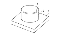
本発明の蛍光体の好ましい結晶構造であるβ−アルミナ構造の代表的な物質は、BaMgAl10O17である。BaMgAl10O17の結晶は六方晶の結晶系をとり、P63/mmcなる空間群をとり、BaOの層がAl2O3の層とMgAl2O4の層とでサンドイッチされた層状構造をとる。Eu2+、Sr2+、及びCa2+は、広い組成範囲でBa2+の格子位置を置換し得る。Mn2+とZn2+は、広い組成範囲でMg2+の格子位置を置換し得る。Mg2+サイトは4配位の酸素配位構造をとっており、この配位構造が作る結晶場が緑色発光に寄与していると考えられている。 A typical substance having a β-alumina structure, which is a preferred crystal structure of the phosphor of the present invention, is BaMgAl 10 O 17 . The BaMgAl 10 O 17 crystal has a hexagonal crystal system, a P6 3 / mmc space group, and a BaO layer sandwiched between an Al 2 O 3 layer and an MgAl 2 O 4 layer. Take. Eu 2+ , Sr 2+ , and Ca 2+ can replace the lattice position of Ba 2+ in a wide composition range. Mn 2+ and Zn 2+ can replace the lattice position of Mg 2+ in a wide composition range. The Mg 2+ site has a tetracoordinate oxygen coordination structure, and it is considered that the crystal field formed by this coordination structure contributes to green light emission.
BaMgAl10O17のMgをAlに、Baの一部をOに置換して得られるBa0.75Al11O17.25のEu付活物質は、青色蛍光体として知られており、BaMgAl10O17:Eu蛍光体と類似の発光特性を有し、互いに固溶して固溶体を形成することが知られている。以上の観点から、本発明の蛍光体の好ましい組成は、上記式[1]で表わされることになる。 Ba 0.75 Al 11 O 17.25 Eu-activating material obtained by substituting Mg of BaMgAl 10 O 17 with Al and a part of Ba with O is known as a blue phosphor, and BaMgAl 10 It has been known that it has a light emission characteristic similar to that of an O 17 : Eu phosphor and forms a solid solution by solid solution with each other. From the above viewpoint, the preferred composition of the phosphor of the present invention is represented by the above formula [1].
特に、本発明の蛍光体が上記式[1]で表わされる組成を有し、且つ、「a」が0又は1ではない場合、本発明の蛍光体は、Ba(1−b−c−d)SrbCacEudMg(1−e−f)ZneMnfAlgOhで表わされる項と、Ba(1−b’−c’−d’)Srb’Cac’Eud’Al11O17.5で表わされる項とを有することになるが、本発明の蛍光体は、これらの項が均一結晶相をなす固溶体であってもよく、また、これらの項からなる異なる結晶相の混合物であってもよい。 In particular, when the phosphor of the present invention has a composition represented by the above formula [1] and “a” is not 0 or 1, the phosphor of the present invention has Ba (1-bcd). ) Sr b Ca c Eu d Mg (1-ef) Zn e Mn f Al g O h and Ba (1-b′-c′-d ′) Sr b ′ Cac ′ Eu d ′ Having terms represented by Al 11 O 17.5 , the phosphor of the present invention may be a solid solution in which these terms form a uniform crystal phase, or different from these terms. It may be a mixture of crystalline phases.
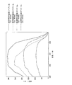
<I−1−4.発光スペクトル>
本発明の蛍光体は、緑色蛍光体又は青色蛍光体としての用途に鑑みて、380nm以上410nm以下の波長範囲の光、特に波長400又は405nmの光で励起した場合における発光スペクトルを測定した場合に、以下の特徴を有することが好ましい。
<I-1-4. Emission spectrum>
The phosphor of the present invention is used in the case of measuring an emission spectrum when excited by light in a wavelength range of 380 nm to 410 nm, particularly light having a wavelength of 400 or 405 nm, in view of the use as a green phosphor or a blue phosphor. It is preferable to have the following characteristics.
(I−1−4−1.発光ピーク波長)
本発明の蛍光体は、緑色蛍光体として使用する場合、上記波長範囲の光で励起して得られる発光スペクトルにおける発光ピーク波長λp(nm)が、通常470nm以上、好ましくは490nm以上、より好ましくは510nm以上、また、通常570nnm以下、好ましくは550nm以下、より好ましくは535nm以下の範囲に存在することが望ましい。発光ピーク波長λpが短過ぎると、発光色が緑色から逸脱し、青緑色となる傾向があり、発光ピーク波長λpが長過ぎると、発光色が緑色から逸脱し、黄緑色となる傾向がある。
(I-1-4-1. Emission peak wavelength)
When the phosphor of the present invention is used as a green phosphor, the emission peak wavelength λ p (nm) in the emission spectrum obtained by excitation with light in the above wavelength range is usually 470 nm or more, preferably 490 nm or more, more preferably Is preferably in the range of 510 nm or more, and usually 570 nm or less, preferably 550 nm or less, more preferably 535 nm or less. When the emission peak wavelength lambda p is too short, departing emission color from green, tend to be blue-green, the emission peak wavelength lambda p is too long, departing emission color from green, it tends to be yellowish green is there.
また、本発明の蛍光体は、青色蛍光体として使用する場合、上記波長範囲の光で励起して得られる発光スペクトルにおける発光ピーク波長λp(nm)が、通常420nm以上、好ましくは430nm以上、より好ましくは440nm以上、また、通常470nm以下、好ましくは465nm以下、より好ましくは460nm以下の範囲に存在することが望ましい。発光ピーク波長λpが短過ぎると、発光色が青色から逸脱し、紫色となる傾向があり、発光ピーク波長λpが長過ぎると、発光色が青色から逸脱し、青緑色となる傾向がある。 In addition, when the phosphor of the present invention is used as a blue phosphor, the emission peak wavelength λp (nm) in the emission spectrum obtained by excitation with light in the above wavelength range is usually 420 nm or more, preferably 430 nm or more. It is preferably 440 nm or more, and usually 470 nm or less, preferably 465 nm or less, more preferably 460 nm or less. If the emission peak wavelength λp is too short, the emission color tends to deviate from blue and becomes purple, and if the emission peak wavelength λp is too long, the emission color tends to deviate from blue and becomes blue-green.
(I−1−4−2.発光ピーク半値幅)
本発明の蛍光体は、上述の発光スペクトルにおける発光ピークの半値幅(full width at half maximum。以下適宜「FWHM」と略称する。)が、通常60nm以下、好ましくは55nm以下、より好ましくは40nm以下、更に好ましくは35nm以下、特に好ましくは30nm以下であることが好ましい。FWHMが広過ぎると、色純度が低下する場合がある。FWHMの下限は制限されないが、FWHMが狭過ぎると輝度が低下する場合があるので、通常3nm以上、好ましくは4nm以上であることが望ましい。
(I-1-4-2. Half width of emission peak)
In the phosphor of the present invention, the full width at half maximum (hereinafter referred to as “FWHM” as appropriate) of the emission peak in the above-mentioned emission spectrum is usually 60 nm or less, preferably 55 nm or less, more preferably 40 nm or less. More preferably, it is 35 nm or less, and particularly preferably 30 nm or less. If the FWHM is too wide, the color purity may decrease. The lower limit of the FWHM is not limited, but if the FWHM is too narrow, the luminance may decrease. Therefore, it is usually 3 nm or more, preferably 4 nm or more.
(I−1−4−3.緑色発光ピークに対する青色発光ピークの強度の割合)
また、本発明の蛍光体は、特にEu及びMnを併有する場合、主に緑色領域の発光を有する蛍光体(緑色蛍光体)となる。この場合、緑色の波長領域に存在する発光ピークに対して、他の波長領域(主に青色の波長領域)に存在する発光ピークが、十分に小さいことが好ましい。
(I-1-4-3. Ratio of intensity of blue emission peak to green emission peak)
Moreover, the phosphor of the present invention becomes a phosphor (green phosphor) mainly having light emission in the green region, particularly when both Eu and Mn are contained. In this case, it is preferable that the emission peak existing in the other wavelength region (mainly the blue wavelength region) is sufficiently smaller than the emission peak existing in the green wavelength region.
具体的には、発光スペクトルにおける、通常490nm以上、好ましくは510nm以上、また、通常550nnm以下、好ましくは535nm以下の領域に存在するピーク(緑色発光ピーク)に対する、通常420nm以上、好ましくは430nm以上、また、通常470nm以下、好ましくは465nm以下の領域に存在するピーク(青色発光ピーク)の強度の割合(緑色発光ピークの大きさを1とした場合の青色発光ピークの大きさ)が、通常0.15以下、好ましくは0.09以下、より好ましくは0.07以下、さらに好ましくは0.06以下、特に好ましくは0.05以下であることが望ましい。緑色発光ピークに対する青色発光ピークの強度の割合の値が大き過ぎると、緑色蛍光体としての性能が十分でなくなる場合がある。 Specifically, it is usually 420 nm or more, preferably 430 nm or more, with respect to a peak (green emission peak) that is usually 490 nm or more, preferably 510 nm or more, and usually 550 nnm or less, preferably 535 nm or less in the emission spectrum. In addition, the ratio of the intensity of the peak (blue emission peak) existing in the region of usually 470 nm or less, preferably 465 nm or less (blue emission peak magnitude when the green emission peak magnitude is 1) is usually 0.00. It is desirably 15 or less, preferably 0.09 or less, more preferably 0.07 or less, further preferably 0.06 or less, and particularly preferably 0.05 or less. If the value of the ratio of the intensity of the blue light emission peak to the green light emission peak is too large, the performance as a green phosphor may not be sufficient.
(I−1−4−4.発光スペクトルの測定)
本発明の蛍光体の発光スペクトルの測定は、例えば、励起光源として150Wキセノンランプを、スペクトル測定装置としてマルチチャンネルCCD検出器C7041(浜松フォトニクス社製)を備える蛍光測定装置(日本分光社製)を用いて行なうことができる。なお、発光スペクトルの測定は、温度25℃において行なうものとする。
(I-1-4-4. Measurement of emission spectrum)
The measurement of the emission spectrum of the phosphor of the present invention is performed, for example, by using a fluorescence measuring apparatus (manufactured by JASCO Corporation) equipped with a 150 W xenon lamp as an excitation light source and a multichannel CCD detector C7041 (manufactured by Hamamatsu Photonics) as a spectrum measuring apparatus. Can be used. The emission spectrum is measured at a temperature of 25 ° C.
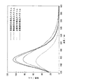
<I−1−5.励起スペクトル>
本発明の蛍光体は、励起スペクトルを測定した場合に、以下の特徴を有することが好ましい。
<I-1-5. Excitation spectrum>
The phosphor of the present invention preferably has the following characteristics when the excitation spectrum is measured.
(I−1−5−1.I(340)に対するI(400)の減少率)
本発明の蛍光体は、励起スペクトルにおける励起波長340nmでの発光強度I(340)と、励起波長400nmでの発光強度I(400)とが、下記式[2]を満たすことが好ましい。
0≦[{I(340)−I(400)}/I(340)]×100≦29 [2]
(I-1-5-1. Reduction rate of I (400) with respect to I (340))
In the phosphor of the present invention, the emission intensity I (340) at an excitation wavelength of 340 nm and the emission intensity I (400) at an excitation wavelength of 400 nm in the excitation spectrum preferably satisfy the following formula [2].
0 ≦ [{I (340) −I (400)} / I (340)] × 100 ≦ 29 [2]
本発明の蛍光体の励起スペクトルの極大点は、概ね波長340nm付近に存在する。即ち、上記式[2]は、励起スペクトルの極大点付近の励起スペクトル強度(I(340))に対する、波長400nmの励起スペクトル強度(I(400))の減少率が低いこと、惹いては、波長400nm付近の励起スペクトル強度が高いことを表わしている。波長400nm付近の励起スペクトル強度が高い蛍光体は、近紫外発光ダイオード(light emitting diode。以下適宜「LED」と略称する。)を励起光源として用いた場合の発光効率に優れるので好ましい。 The maximum point of the excitation spectrum of the phosphor of the present invention is approximately in the vicinity of a wavelength of 340 nm. That is, the above formula [2] has a low reduction rate of the excitation spectrum intensity (I (400)) at a wavelength of 400 nm with respect to the excitation spectrum intensity (I (340)) near the maximum point of the excitation spectrum. This indicates that the excitation spectrum intensity near the wavelength of 400 nm is high. A phosphor having a high excitation spectral intensity around a wavelength of 400 nm is preferable because it has excellent luminous efficiency when a near-ultraviolet light emitting diode (hereinafter referred to as “LED” as appropriate) is used as an excitation light source.
具体的に、上記式[2]における[{I(340)−I(400)}/I(340)]×100の値の上限は、小さければ小さいほど好ましいが、通常29以下、好ましくは26以下、より好ましくは23以下であることが望ましい。
一方、[{I(340)−I(400)}/I(340)]×100の値の下限は制限されないが、通常0以上である。
Specifically, the upper limit of the value of [{I (340) −I (400)} / I (340)] × 100 in the above formula [2] is preferably as small as possible, but is usually 29 or less, preferably 26. Below, it is desirable that it is 23 or less.
On the other hand, the lower limit of the value of [{I (340) −I (400)} / I (340)] × 100 is not limited, but is usually 0 or more.
(I−1−5−2.I(382)に対するI(390)の変化率)
また、本発明の蛍光体は、励起スペクトルにおける励起波長382nmでの発光強度I(382)と、励起波長390nmでの発光強度I(390)とが、下記式[3]を満たすことが望ましい。
0≦|[{I(382)−I(390)}/I(382)]|×100≦3.1 [3]
(Change rate of I (390) with respect to I-1-5-2.I (382))
In the phosphor of the present invention, it is desirable that the emission intensity I (382) at the excitation wavelength 382 nm and the emission intensity I (390) at the excitation wavelength 390 nm satisfy the following formula [3] in the excitation spectrum.
0 ≦ | [{I (382) −I (390)} / I (382)] | × 100 ≦ 3.1 [3]
上記式[3]は、波長382nmの励起スペクトル強度(I(382))に対する、波長390nmの励起スペクトル強度(I(390))の変化率が低いこと、惹いては、382nmから390nmにかけての波長範囲における励起スペクトルの形状が平坦であることを表わしている。この382nmから390nmにかけての波長範囲は、主に近紫外励起に用いられる励起波長である。よって、この波長範囲における励起スペクトルの形状が平坦な蛍光体は、近紫外LEDを励起光源として用いた場合に、発光強度の低下や色ずれが生じ難いので好ましい。 The above formula [3] indicates that the rate of change of the excitation spectrum intensity (I (390)) at the wavelength 390 nm is low with respect to the excitation spectrum intensity (I (382)) at the wavelength 382 nm, and that the wavelength from 382 nm to 390 nm. It represents that the shape of the excitation spectrum in the range is flat. This wavelength range from 382 nm to 390 nm is an excitation wavelength mainly used for near ultraviolet excitation. Therefore, a phosphor having a flat excitation spectrum in this wavelength range is preferable because a decrease in emission intensity and a color shift hardly occur when a near-ultraviolet LED is used as an excitation light source.
具体的に、上記式[3]における|[{I(382)−I(390)}/I(382)]|×100の値の上限は、小さければ小さいほど好ましいが、通常3.1以下、好ましくは2.5以下、より好ましくは2以下、更に好ましくは1.5以下であることが望ましい。
一方、|[{I(382)−I(390)}/I(382)]|×100の値の下限は制限されないが、通常0以上である。
Specifically, the upper limit of the value of | [{I (382) −I (390)} / I (382)] | × 100 in the above formula [3] is preferably as small as possible, but is usually 3.1 or less. Preferably, it is 2.5 or less, more preferably 2 or less, and still more preferably 1.5 or less.
On the other hand, the lower limit of the value of | [{I (382) −I (390)} / I (382)] | × 100 is not limited, but is usually 0 or more.
(I−1−5−3.励起スペクトルの測定)
本発明の蛍光体の励起スペクトルの測定は、例えば、励起光源として150Wキセノンランプを、スペクトル測定装置としてマルチチャンネルCCD検出器C7041(浜松フォトニクス社製)を備える蛍光測定装置(日本分光社製)を用いて行なうことができる。なお、励起スペクトルの測定は、温度25℃において行なうものとする。
(I-1-5-3. Measurement of excitation spectrum)
The excitation spectrum of the phosphor of the present invention is measured, for example, by using a fluorescence measuring apparatus (manufactured by JASCO Corporation) equipped with a 150 W xenon lamp as an excitation light source and a multichannel CCD detector C7041 (manufactured by Hamamatsu Photonics) as a spectrum measuring apparatus. Can be used. The excitation spectrum is measured at a temperature of 25 ° C.
<I−1−6.温度特性>
本発明の蛍光体は、波長405nmの光で励起して発光スペクトルを測定した場合に、以下の温度特性を有することが好ましい。
<I-1-6. Temperature characteristics>
The phosphor of the present invention preferably has the following temperature characteristics when the emission spectrum is measured by excitation with light having a wavelength of 405 nm.
(I−1−6−1.温度変化に対する輝度の安定性)
本発明の蛍光体は、20℃±5℃、60℃±5℃、100℃±5℃、135℃±10℃及び175℃±10℃における励起波長405nmでの輝度値を、順に「B(405) (20)」、「B(405) (60)」、「B(405) (100)」、「B(405) (135)」及び「B(405) (175)」とした場合に、下記式[4−1]〜[4−4]で表わされる関係を満たすことが好ましい。
0≦|[B(405) (60)−B(405) (20)]/B(405) (20)|×100≦8 [4−1]
0≦|[B(405) (100)−B(405) (20)]/B(405) (20)|×100≦8 [4−2]
0≦|[B(405) (135)−B(405) (20)]/B(405) (20)|×100≦8 [4−3]
0≦|[B(405) (175)−B(405) (20)]/B(405) (20)|×100≦8 [4−4]
(I-1-6-1. Luminance stability against temperature change)
Phosphor of the present invention, 20 ℃ ± 5 ℃, 60 ℃ ± 5 ℃, 100 ℃ ± 5 ℃, the luminance value at an excitation wavelength of 405nm at 135 ° C. ± 10 ° C. and 175 ° C. ± 10 ° C., in order "B ( 405) (20) "," B (405) (60) "," B (405) (100) "," B (405) (135) "and" B (405) (175) " It is preferable that the relationships represented by the following formulas [4-1] to [4-4] are satisfied.
0 ≦ | [B (405) (60) −B (405) (20) ] / B (405) (20) | × 100 ≦ 8 [4-1]
0 ≦ | [B (405) (100) −B (405) (20) ] / B (405) (20) | × 100 ≦ 8 [4-2]
0 ≦ | [B (405) (135) −B (405) (20) ] / B (405) (20) | × 100 ≦ 8 [4-3]
0 ≦ | [B (405) (175) −B (405) (20) ] / B (405) (20) | × 100 ≦ 8 [4-4]
上記式[4−1]〜[4−4]は、20℃±5℃における励起波長405nmでの輝度値(B(405) (20))に対する、60℃±5℃、100℃±5℃、135℃±10℃及び175℃±10℃における励起波長405nmでの輝度値(B(405) (60)、B(405) (100)、B(405) (135)、B(405) (175))の変化率が低いこと、惹いては、温度変化に対する輝度の安定性に優れていることを表わす。 The above formulas [4-1] to [4-4] are 60 ° C. ± 5 ° C. and 100 ° C. ± 5 ° C. with respect to the luminance value (B (405) (20) ) at an excitation wavelength of 405 nm at 20 ° C. ± 5 ° C. , 135 ° C. ± 10 ° C. and 175 ° C. ± 10 ° C. at the excitation wavelength of 405 nm (B (405) (60) , B (405) (100) , B (405) (135) , B (405) ( 175) It indicates that the change rate of) is low, and that the luminance stability with respect to temperature change is excellent.
具体的に、上記式[4−1]における|[B(405) (60)−B(405) (20)]/B(405) (20)|×100の値、上記式[4−2]における|[B(405) (100)−B(405) (20)]/B(405) (20)|×100の値、上記式[4−3]における|[B(405) (135)−B(405) (20)]/B(405) (20)|×100の値、及び、上記式[4−4]における|[B(405) (175)−B(405) (20)]/B(405) (20)|×100の値の上限は、何れも、通常8以下、好ましくは5以下、より好ましくは3以下であることが望ましい。
一方、これらの値の下限は制限されず、理想的には0である。
Specifically, the value of | [B (405) (60) −B (405) (20) ] / B (405) (20) | × 100 in the above equation [4-1], the above equation [4-2 ] | [B (405) (100) −B (405) (20) ] / B (405) (20) The value of | × 100, | [B (405) (135 ) in the above formula [4-3]. ) -B (405) (20) ] / B (405) (20) | values of × 100, and, in the formula [4-4] | [B (405 ) (175) -B (405) (20 )] / B (405) ( 20) | limit value × 100, any, usually 8 or less, preferably 5 or less, and more preferably 3 or less.
On the other hand, the lower limit of these values is not limited and is ideally 0.
(I−1−6−2.温度変化に対する発光強度の安定性)
本発明の蛍光体は、20℃±5℃、60℃±5℃、100℃±5℃、135℃±10℃及び175℃±10℃における励起波長405nmでの発光ピーク強度を、順に「I(405) (20)」、「I(405) (60)」、「I(405) (100)」、「I(405) (135)」及び「I(405) (175)」とした場合に、下記式[5−1]〜[5−4]で表わされる関係を満たすことが好ましい。
0≦|[I(405) (60)−I(405) (20)]/I(405) (20)|×100≦30 [5−1]
0≦|[I(405) (100)−I(405) (20)]/I(405) (20)|×100≦30 [5−2]
0≦|[I(405) (135)−I(405) (20)]/I(405) (20)|×100≦30 [5−3]
0≦|[I(405) (175)−I(405) (20)]/I(405) (20)|×100≦30 [5−4]
(I-1-6-2. Stability of emission intensity against temperature change)
The phosphor of the present invention has emission peak intensities at excitation wavelengths of 405 nm at 20 ° C. ± 5 ° C., 60 ° C. ± 5 ° C., 100 ° C. ± 5 ° C., 135 ° C. ± 10 ° C. and 175 ° C. ± 10 ° C. (405) (20) "," I (405) (60) "," I (405) (100) "," I (405) (135) "and" I (405) (175) " In addition, it is preferable that the relationships represented by the following formulas [5-1] to [5-4] are satisfied.
0 ≦ | [I (405) (60) −I (405) (20) ] / I (405) (20) | × 100 ≦ 30 [5-1]
0 ≦ | [I (405) (100) −I (405) (20) ] / I (405) (20) | × 100 ≦ 30 [5-2]
0 ≦ | [I (405) (135) −I (405) (20) ] / I (405) (20) | × 100 ≦ 30 [5-3]
0 ≦ | [I (405) (175) −I (405) (20) ] / I (405) (20) | × 100 ≦ 30 [5-4]
上記式[5−1]〜[5−4]は、20℃±5℃における励起波長405nmでの発光ピーク強度(I(405) (20))に対する、60℃±5℃、100℃±5℃、135℃±10℃及び175℃±10℃における励起波長405nmでの発光ピーク強度(I(405) (60)、I(405) (100)、I(405) (135)、I(405) (175))の変化率が低いこと、惹いては、温度変化に対する発光強度の安定性に優れていることを表わす。 The above formulas [5-1] to [5-4] are 60 ° C. ± 5 ° C. and 100 ° C. ± 5 for the emission peak intensity (I (405) (20) ) at an excitation wavelength of 405 nm at 20 ° C. ± 5 ° C. Emission peak intensities (I (405) (60) , I (405) (100) , I (405) (135) , I (405 ) ) (175) It indicates that the rate of change in () is low, and that the emission intensity is stable with respect to temperature changes.
具体的に、上記式[5−1]における|[I(405) (60)−I(405) (20)]/I(405) (20)|×100の値、上記式[5−2]における|[I(405) (100)−I(405) (20)]/I(405) (20)|×100の値、上記式[5−3]における|[I(405) (135)−I(405) (20)]/I(405) (20)|×100の値、及び、上記式[5−4]における|[I(405) (175)−I(405) (20)]/I(405) (20)|×100の値の上限は、何れも、通常30以下、好ましくは25以下、より好ましくは20以下であることが望ましい。
一方、これらの値の下限は制限されず、理想的には0である。
Specifically, the value of | [I (405) (60) −I (405) (20) ] / I (405) (20) | × 100 in the above formula [5-1], the above formula [5-2] ] | [I (405) (100) −I (405) (20) ] / I (405) (20) The value of | × 100, | [I (405) (135 ) in the above formula [5-3] ) -I (405) (20) ] / I (405) (20) | values of × 100, and, in the formula [5-4] | [I (405 ) (175) -I (405) (20 )] / I (405) ( 20) | limit value × 100, any, usually 30 or less, preferably 25 or less, and more preferably 20 or less.
On the other hand, the lower limit of these values is not limited and is ideally 0.
ここで、発光強度の変化率は、温度が高くなるほど大きくなるものであり、上記式[5−1]〜[5−4]のうち、通常、[5−4]の値が最も大きくなる。従って、特に[5−4]の式を満たすかどうかが高温安定性の点では重要である。更に、[5−3]の式においては、上限が15以下になっていることが好ましい。また、[5−1]及び[5−2]の式においては、上限が15以下になっていることが好ましく、10以下となっていることが更に好ましい。 Here, the change rate of the emission intensity increases as the temperature increases, and among the above formulas [5-1] to [5-4], the value of [5-4] is usually the largest. Therefore, whether or not the expression [5-4] is satisfied is particularly important in terms of high-temperature stability. Furthermore, in the formula [5-3], the upper limit is preferably 15 or less. In the formulas [5-1] and [5-2], the upper limit is preferably 15 or less, and more preferably 10 or less.
(I−1−6−3.温度特性の測定)
上記温度特性を測定する場合は、例えば、発光スペクトル装置として大塚電子製MCPD7000マルチチャンネルスペクトル測定装置、輝度測定装置として色彩輝度計BM5A、ペルチェ素子による冷却機構とヒーターによる加熱機構を備えたステージ及び光源として150Wキセノンランプを備える装置を用いて、下記手順で測定することができる。
(I-1-6-3. Measurement of temperature characteristics)
When measuring the temperature characteristics, for example, a MCPD7000 multi-channel spectrum measuring device manufactured by Otsuka Electronics as an emission spectrum device, a color luminance meter BM5A as a luminance measuring device, a stage and a light source provided with a cooling mechanism using a Peltier element and a heating mechanism using a heater Can be measured by the following procedure using a device equipped with a 150 W xenon lamp.
ステージに蛍光体のサンプルを入れたセルを載せ、温度を20℃から175℃までの範囲で段階的に変化させる。蛍光体の表面温度を確認し、次いで、光源から回折格子で分光して取り出した波長405nmの光で蛍光体を励起して、輝度値及び発光スペクトルを測定する。測定された発光スペクトルから、発光ピーク強度を求める。ここで、蛍光体の励起光照射側の表面温度の測定値は、放射温度計と熱電対による温度測定値を利用して補正した値を用いる。 A cell containing a phosphor sample is placed on the stage, and the temperature is changed stepwise in the range from 20 ° C to 175 ° C. After confirming the surface temperature of the phosphor, the phosphor is excited with light having a wavelength of 405 nm extracted from the light source with a diffraction grating, and a luminance value and an emission spectrum are measured. The emission peak intensity is obtained from the measured emission spectrum. Here, as the measured value of the surface temperature on the excitation light irradiation side of the phosphor, a value corrected using the measured temperature value by the radiation thermometer and the thermocouple is used.
<I−1−7.重量メジアン径>
本発明の蛍光体の重量メジアン径(D50)は、本発明の効果を著しく損なわない限り任意であるが、通常0.1μm以上、好ましくは0.5μm以上、また、通常30μm以下、好ましくは20μm以下の範囲であることが望ましい。重量メジアン径が小さ過ぎると、輝度が低下し、蛍光体粒子が凝集してしまう傾向がある。一方、重量メジアン径が大き過ぎると、塗布ムラやディスペンサー等の閉塞が生じる傾向がある。本発明の蛍光体の重量メジアン径は、例えばレーザー回折/散乱式粒度分布測定装置等の装置を用いて測定することができる。
<I-1-7. Weight median diameter>
The weight median diameter (D 50 ) of the phosphor of the present invention is arbitrary as long as the effect of the present invention is not significantly impaired, but is usually 0.1 μm or more, preferably 0.5 μm or more, and usually 30 μm or less, preferably A range of 20 μm or less is desirable. When the weight median diameter is too small, the luminance is lowered and the phosphor particles tend to aggregate. On the other hand, if the weight median diameter is too large, there is a tendency for coating unevenness and blockage of a dispenser or the like to occur. The weight median diameter of the phosphor of the present invention can be measured using an apparatus such as a laser diffraction / scattering particle size distribution measuring apparatus.
本発明の蛍光体のうち、特に上記一般式[1]で表わされる蛍光体に関しては、その蛍光体の1次粒子は通常六角柱であって、凝集の少ない単粒子となる。
この六角柱の柱の高さは結晶格子のc軸方向の厚みを表わすこととなるが、該c軸方向の平均厚みとしては、好ましくは2μm以上、より好ましくは2.5μm以上、さらに好ましくは3μm以上、中でも好ましくは3.3μm以上、特に好ましくは3.5μm以上である。該平均厚みの測定においては、通常、SEM(走査型電子顕微鏡)が用いられる。具体的には、SEM画像上の多数の1次粒子の六角柱は様々な方向を向いているので、観測される六角形の隣り合う3辺の長さ及び六角柱の高さから投射法の原理を用いて、実際の六角柱の高さを求めることとなる。
Among the phosphors of the present invention, in particular, with respect to the phosphor represented by the general formula [1], the primary particles of the phosphor are usually hexagonal columns and become single particles with little aggregation.
The height of the hexagonal column represents the thickness of the crystal lattice in the c-axis direction, and the average thickness in the c-axis direction is preferably 2 μm or more, more preferably 2.5 μm or more, and even more preferably. It is 3 μm or more, preferably 3.3 μm or more, particularly preferably 3.5 μm or more. In measuring the average thickness, SEM (scanning electron microscope) is usually used. Specifically, since the hexagonal cylinders of a large number of primary particles on the SEM image are directed in various directions, the projection method determines the length of the three adjacent sides of the hexagon and the height of the hexagonal cylinder. Using the principle, the actual height of the hexagonal column is obtained.
上記測定を行なう際には、通常10個以上、好ましくは30個以上、より好ましくは100個以上、更に好ましくは300個以上の粒子について測定を行なうことが望ましいが、実際に測定する個数は全結晶粒子に対する割合とも関連する。全ての粒子について測定を行なうのが理想的であるが、通常は、全粒子数に対して15%以上、好ましくは30%以上、より好ましくは50%以上、更に好ましくは80%以上となるような個数について測定すればよい。 When performing the above measurement, it is desirable to perform measurement on particles of usually 10 or more, preferably 30 or more, more preferably 100 or more, and still more preferably 300 or more. It is also related to the ratio to crystal grains. Ideally, the measurement should be performed for all particles, but it is usually 15% or more, preferably 30% or more, more preferably 50% or more, and even more preferably 80% or more based on the total number of particles. What is necessary is just to measure about a small number.
〔I−2.蛍光体の製造方法〕
本発明の蛍光体の製造方法は特に制限されないが、例えば、蛍光体を構成する各元素の原料を粉砕・混合し(粉砕・混合工程)、得られた混合物(これを以下「蛍光体前駆体」という場合がある。)を焼成する(焼成工程)ことにより製造することができる。
なお、以下の記載では、本発明の蛍光体を構成する各元素の原料を、その元素の原子記号に「源」を付して表わす。例えば、Alの原料は「Al源」と表わされる。また、これらの原料をまとめて「各元素の原料」という場合がある。
[I-2. (Method for producing phosphor)
The method for producing the phosphor of the present invention is not particularly limited. For example, the raw materials of each element constituting the phosphor are pulverized and mixed (pulverization / mixing step), and the resulting mixture (hereinafter referred to as “phosphor precursor”). Can be produced by firing (firing step).
In the following description, the raw material of each element constituting the phosphor of the present invention is represented by adding “source” to the atomic symbol of the element. For example, an Al raw material is represented as “Al source”. These raw materials may be collectively referred to as “raw materials for each element”.
<I−2−1.原料>
本発明の蛍光体の原料としては、蛍光体を構成する各元素の原料を用いる。使用する各元素の原料の組み合わせや比率は制限されず、目的とする蛍光体の組成に応じて適宜選択することができる。
<I-2-1. Raw material>
As a raw material of the phosphor of the present invention, a raw material of each element constituting the phosphor is used. The combination and ratio of the raw materials for each element to be used are not limited and can be appropriately selected according to the composition of the target phosphor.
本発明の蛍光体の製造に使用される各元素の原料の例としては、各元素の酸化物、水酸化物、炭酸塩、硝酸塩、硫酸塩、蓚酸塩、カルボン酸塩、ハロゲン化物等が挙げられる。これらの化合物の中から、複合酸化物への反応性や、焼成時における窒素酸化物(NOx)、硫黄酸化物(SOx)等の発生量の低さ等を考慮して、適宜選択すればよい。 Examples of raw materials for each element used in the production of the phosphor of the present invention include oxides, hydroxides, carbonates, nitrates, sulfates, oxalates, carboxylates, halides and the like of each element. It is done. From these compounds, it is appropriately selected in consideration of the reactivity to the composite oxide and the low generation amount of nitrogen oxide (NO x ) and sulfur oxide (SO x ) during firing. That's fine.
各元素の原料の具体例を、元素の種類毎に分けて列挙すると、以下の通りである。 Specific examples of raw materials for each element are listed as follows for each element type.
Al源の具体例としては、Al2O3、Al(OH)3、AlOOH、Al(NO3)3・9H2O、Al2(SO4)3、Al2Cl3等が挙げられる。中でもAl2O3、Al(NO3)3・9H2O等が好ましい。 Specific examples of the Al source include Al 2 O 3 , Al (OH) 3 , AlOOH, Al (NO 3 ) 3 .9H 2 O, Al 2 (SO 4 ) 3 , Al 2 Cl 3 and the like. Among them, Al 2 O 3, Al (NO 3) 3 · 9H 2 O and the like are preferable.
Ba源の具体例としては、BaO、Ba(OH)2・8H2O、BaCO3、Ba(NO3)2、BaSO4、Ba(OCO)2・2H2O、Ba(OCOCH3)2、BaCl2等が挙げられる。中でもBa(OH)2・8H2O、Ba(NO3)2、BaCO3等が好ましい。 Specific examples of the Ba source include BaO, Ba (OH) 2 .8H 2 O, BaCO 3 , Ba (NO 3 ) 2 , BaSO 4 , Ba (OCO) 2 .2H 2 O, Ba (OCOCH 3 ) 2 , BaCl 2, and the like. Of these, Ba (OH) 2 .8H 2 O, Ba (NO 3 ) 2 , BaCO 3 and the like are preferable.
Sr源の具体例としては、SrO、Sr(OH)2・8H2O、SrCO3、Sr(NO3)2、SrSO4、Sr(OCO)2・H2O、Sr(OCOCH3)2・0.5H2O、SrCl2等が挙げられる。中でもSrCO3、Sr(NO3)2、Sr(OH)2・8H2O等が好ましい。 Specific examples of the Sr source include SrO, Sr (OH) 2 .8H 2 O, SrCO 3 , Sr (NO 3 ) 2 , SrSO 4 , Sr (OCO) 2 .H 2 O, Sr (OCOCH 3 ) 2. 0.5H 2 O, SrCl 2 and the like can be mentioned. Of these, SrCO 3 , Sr (NO 3 ) 2 , Sr (OH) 2 .8H 2 O and the like are preferable.
Eu源の具体例としては、Eu2O3、Eu2(SO4)3、Eu2(OCO)6、EuCl2、EuCl3、EuF3、Eu(NO3)3・6H2O等が挙げられる。中でもEu2O3、EuF3、EuCl3等が好ましい。 Specific examples of the Eu source include Eu 2 O 3 , Eu 2 (SO 4 ) 3 , Eu 2 (OCO) 6 , EuCl 2 , EuCl 3 , EuF 3 , Eu (NO 3 ) 3 .6H 2 O and the like. It is done. Of these, Eu 2 O 3 , EuF 3 , EuCl 3 and the like are preferable.
Mn源の具体例としては、Mn(NO3)2・6H2O、MnO2、Mn2O3、Mn3O4、MnO、Mn(OH)2、MnCO3、Mn(OCOCH3)2・2H2O、Mn(OCOCH3)3・nH2O、MnCl2・4H2O等が挙げられる。中でもMnCO3、Mn(NO3)2・6H2O、MnO等が好ましい。 Specific examples of the Mn source include Mn (NO 3 ) 2 .6H 2 O, MnO 2 , Mn 2 O 3 , Mn 3 O 4 , MnO, Mn (OH) 2 , MnCO 3 , Mn (OCOCH 3 ) 2. 2H 2 O, Mn (OCOCH 3 ) 3 .nH 2 O, MnCl 2 .4H 2 O, and the like can be given. Of these, MnCO 3 , Mn (NO 3 ) 2 .6H 2 O, MnO and the like are preferable.
Mg源の具体例としては、Mg(OH)2、Mg(NO3)2・6H2O、Mg(OCOCH3)2・4H2O、MgCl2、MgCO3、塩基性炭酸マグネシウム、MgO、MgSO4、Mg(C2O4)・2H2O等が挙げられる。中でもMgCO3、塩基性炭酸マグネシウム、MgO等が好ましい。 Specific examples of the Mg source include Mg (OH) 2 , Mg (NO 3 ) 2 .6H 2 O, Mg (OCOCH 3 ) 2 .4H 2 O, MgCl 2 , MgCO 3 , basic magnesium carbonate, MgO, MgSO 4 , Mg (C 2 O 4 ) · 2H 2 O, and the like. Of these, MgCO 3 , basic magnesium carbonate, MgO and the like are preferable.
Ca源の具体例としては、CaO、Ca(OH)2、CaCO3、Ca(NO3)2・4H2O、CaSO4・2H2O、Ca(OCO)2・H2O、Ca(OCOCH3)2・H2O、CaCl2等が挙げられる。中でもCaCO3、Ca(NO3)2・4H2O、CaCl2等が好ましい。 Specific examples of the Ca source include CaO, Ca (OH) 2 , CaCO 3 , Ca (NO 3 ) 2 .4H 2 O, CaSO 4 .2H 2 O, Ca (OCO) 2 .H 2 O, and Ca (OCOCH). 3 ) 2 · H 2 O, CaCl 2 and the like. Of these, CaCO 3 , Ca (NO 3 ) 2 .4H 2 O, CaCl 2 and the like are preferable.
Zn源の具体例としては、ZnO、ZnF2、ZnCl2、Zn(OH)2、Zn(C2O4)・2H2O、ZnSO4・7H2O等が挙げられる。 Specific examples of the Zn source include ZnO, ZnF 2 , ZnCl 2 , Zn (OH) 2 , Zn (C 2 O 4 ) · 2H 2 O, ZnSO 4 · 7H 2 O, and the like.
これらの各元素の原料は、何れの元素についても、何れか一種を単独で用いてもよく、二種以上を任意の組み合わせ及び比率で併用してもよい。 As for the raw materials for these elements, any one of these elements may be used alone, or two or more may be used in any combination and ratio.
<I−2−2.粉砕・混合工程>
各元素の原料を粉砕・混合する手法は特に制限されないが、例としては、下記の(A)及び(B)として挙げられたような公知の手法を任意に用いることができる。また、これらの各種条件については、例えば、ボールミルにおいて2種の粒径の異なるボールを混合して用いる等、公知の条件が適宜選択可能である。
<I-2-2. Grinding and mixing process>
The method for pulverizing and mixing the raw materials of each element is not particularly limited, but as an example, known methods such as those listed below as (A) and (B) can be arbitrarily used. As for these various conditions, for example, known conditions such as mixing and using two kinds of balls having different particle diameters in a ball mill can be appropriately selected.
(A)ハンマーミル、ロールミル、ボールミル、ジェットミル等の乾式粉砕機、又は、乳鉢と乳棒等を用いる粉砕と、リボンブレンダー、V型ブレンダー、ヘンシェルミキサー等の混合機、又は、乳鉢と乳棒を用いる混合とを組み合わせ、各元素の原料等の原料を粉砕混合する乾式混合法。本手法においては、各元素の原料を粉砕してから混合してもよく、混合してから粉砕してもよく、更には粉砕と混合を同時に行なってもよい。 (A) Dry pulverizer such as hammer mill, roll mill, ball mill, jet mill, etc., pulverization using mortar and pestle, etc., mixer such as ribbon blender, V-type blender and Henschel mixer, or mortar and pestle A dry mixing method that combines mixing and pulverizing and mixing raw materials such as raw materials for each element. In this method, the raw materials of each element may be pulverized and mixed, mixed and then pulverized, or pulverization and mixing may be performed simultaneously.
(B)各元素の原料にエタノール等のアルコール系溶媒又は水等の溶媒又は分散媒を加え、媒体攪拌式粉砕機等の湿式粉砕機や、乳鉢と乳棒、蒸発皿と撹拌棒等を用いて粉砕・混合した後、水等の媒体中に加え混合することにより、溶液又はスラリーの状態とした上で、噴霧乾燥、加熱乾燥、又は自然乾燥等により乾燥させる湿式法。 (B) Add an alcoholic solvent such as ethanol or a solvent such as water or a dispersion medium to the raw materials of each element, and use a wet pulverizer such as a medium stirring pulverizer, a mortar and pestle, an evaporating dish and a stirring rod, etc. A wet method in which, after pulverization and mixing, the mixture is added to a medium such as water and mixed to form a solution or slurry, and then dried by spray drying, heat drying, or natural drying.
これらの粉砕・混合法の中でも、特に、発光中心イオンとなる元素の原料については、少量の化合物を全体に均一に混合、分散させることが望まれることから、液体媒体を用いる手法が好ましく、また、他の元素の原料についても全体に均一な混合が得られるという点から、(B)湿式法が好ましい。なお、湿式法の媒体(溶媒又は分散媒)としては、制限されるものではないが、水又はエタノール等が好ましい。
また、上記混合・粉砕時に、必要に応じて、蛍光体原料を篩いにかけても良い。この場合、各種市販の篩いを用いることが可能であるが、金属メッシュのものよりもナイロンメッシュ等の樹脂製のものを用いる方が、不純物混入防止の点で好ましい。
Among these pulverization / mixing methods, the method using a liquid medium is preferred because it is desired to mix and disperse a small amount of the compound uniformly, especially for the raw material of the element that becomes the luminescent center ion. From the point that uniform mixing can be obtained as a whole for the raw materials of other elements, the (B) wet method is preferable. In addition, although it does not restrict | limit as a medium (solvent or dispersion medium) of a wet method, Water or ethanol etc. are preferable.
In addition, the phosphor material may be sieved as necessary during the mixing and pulverization. In this case, various types of commercially available sieves can be used, but it is preferable to use a resin mesh such as a nylon mesh rather than a metal mesh in terms of preventing impurities from being mixed.
<I−2−3.焼成工程>
(I−2−3−1.焼成条件)
得られた混合物を、各蛍光体原料と反応性の低い材料からなるルツボ又はトレイ等の耐熱容器中に充填する。このような焼成時に用いる耐熱容器の材質としては、例えば、アルミナ、石英、窒化ホウ素、窒化珪素、炭化珪素、マグネシウム、ムライト等のセラミックス、白金、モリブデン、タングステン、タンタル、ニオブ、イリジウム、ロジウム等の金属、あるいは、それらを主成分とする合金、カーボン(グラファイト)などが挙げられる。ここで、石英製の耐熱容器は、比較的低温、すなわち、1200℃以下での熱処理に使用することができ、好ましい使用温度範囲は1000℃以下である。
<I-2-3. Firing step>
(I-2-3-1. Firing conditions)
The obtained mixture is filled in a heat-resistant container such as a crucible or a tray made of a material having low reactivity with each phosphor raw material. Examples of the material of the heat-resistant container used at the time of firing include ceramics such as alumina, quartz, boron nitride, silicon nitride, silicon carbide, magnesium, mullite, platinum, molybdenum, tungsten, tantalum, niobium, iridium, rhodium, and the like. Examples thereof include metals, alloys containing them as main components, and carbon (graphite). Here, the heat-resistant container made of quartz can be used for heat treatment at a relatively low temperature, that is, 1200 ° C. or less, and a preferable use temperature range is 1000 ° C. or less.
このような耐熱容器の例として、好ましくはアルミナ製、窒化ホウ素製、窒化珪素製、白金製、モリブデン製、タングステン製、タンタル製の耐熱容器が挙げられる。また、中でも耐熱容器としてはアルミナ製、窒化ホウ素製又はモリブデン製のものを用いることが好ましく、中でも窒素−水素環源雰囲気での焼成温度域で安定なアルミナ製のものがより好ましい。 Examples of such heat resistant containers are preferably heat resistant containers made of alumina, boron nitride, silicon nitride, platinum, molybdenum, tungsten, or tantalum. In particular, as the heat-resistant container, it is preferable to use a product made of alumina, boron nitride or molybdenum, and more preferably a product made of alumina which is stable in a firing temperature range in a nitrogen-hydrogen ring source atmosphere.
なお、蛍光体前駆体を前記耐熱容器内へ充填する際の充填率(以下、「耐熱容器内充填率」と称する。)は、焼成条件によっても異なるが、後述する後処理工程において焼成物を粉砕しにくくならない程度に充填すれば良く、通常10体積%以上、通常90体積%以下である。また、ルツボに充填された蛍光体前駆体は蛍光体原料の粒子同士の間に空隙率を有するため、蛍光体前駆体が充填された耐熱容器の容積100ml当たりに占める蛍光体原料自体の体積としては、通常10ml以上、好ましくは15ml以上、より好ましくは20ml以上であり、また、通常50ml以下、より好ましくは40ml以下、さらに好ましくは30ml以下である。 The filling rate when filling the phosphor precursor into the heat-resistant container (hereinafter referred to as “heat-resistant container filling rate”) varies depending on the firing conditions, but the fired product in the post-treatment step described later is used. What is necessary is just to fill to such an extent that it becomes difficult to grind | pulverize, and they are 10 volume% or more normally and 90 volume% or less normally. In addition, since the phosphor precursor filled in the crucible has a void ratio between the particles of the phosphor precursor, the volume of the phosphor precursor itself occupying per 100 ml of the heat resistant container filled with the phosphor precursor is Is usually 10 ml or more, preferably 15 ml or more, more preferably 20 ml or more, and usually 50 ml or less, more preferably 40 ml or less, still more preferably 30 ml or less.
また、一度に処理する蛍光体前駆体の量を増やしたいときは、昇温速度を減速する等、耐熱容器内に熱が均一に周るようにすることが好ましい。
また、耐熱容器を炉内に充填する際の充填率(以下適宜、「炉内充填率」と称する)は、炉内の耐熱容器間で熱が不均一にならない程度につめることが好ましい。
さらに、上記焼成において、焼成炉中の耐熱容器の数が多い場合には、例えば、上記の昇温速度を遅めにする等、各耐熱容器への熱の伝わり具合を均等にすることが、ムラなく焼成するためには好ましい。
またここで、蛍光体原料として金属炭酸塩を用いている場合には、脱離する二酸化炭素により焼成炉が傷まないよう、予備焼成を行い、少なくとも一部を金属酸化物に変換することが好ましい。
In addition, when it is desired to increase the amount of the phosphor precursor to be processed at a time, it is preferable that the heat surrounds uniformly in the heat-resistant container, for example, by decreasing the rate of temperature rise.
Further, it is preferable that the filling rate when filling the heat-resistant container into the furnace (hereinafter, referred to as “furnace filling ratio” as appropriate) is such that the heat does not become uneven between the heat-resistant containers in the furnace.
Furthermore, in the above baking, when the number of heat-resistant containers in the baking furnace is large, for example, to make the heat transfer to each heat-resistant container uniform, such as slowing the temperature increase rate, It is preferable for firing without unevenness.
Here, when a metal carbonate is used as the phosphor raw material, it is preferable to perform preliminary firing so that the calcining furnace is not damaged by the desorbed carbon dioxide, and at least a part thereof is converted to a metal oxide. .
焼成時の昇温過程においては、その一部で減圧条件下とすることが好ましい。具体的には、好ましくは室温以上であって、好ましくは1500℃以下、より好ましくは1200℃以下、更に好ましくは1000℃以下の温度となっているいずれかの時点において、減圧状態(具体的には通常10−2Pa以上0.1MPa未満の範囲)とすることが好ましい。中でも、系内を減圧下後で後述する不活性ガス又は還元性ガスを系内に導入し、その状態で昇温を行うことが好ましい。
このとき、必要に応じて、目的とする温度で1分以上、好ましくは5分以上、より好ましくは10分以上保持しても良い。保持時間は通常5時間以下、好ましくは3時間以下、より好ましくは1時間以下である。
In the temperature raising process at the time of firing, it is preferable that a part of the temperature is reduced. Specifically, at any time when the temperature is preferably room temperature or higher, preferably 1500 ° C. or lower, more preferably 1200 ° C. or lower, and still more preferably 1000 ° C. or lower, a reduced pressure state (specifically Is usually preferably in the range of 10 −2 Pa or more and less than 0.1 MPa. Among them, it is preferable to introduce an inert gas or a reducing gas, which will be described later, into the system after reducing the pressure in the system and raise the temperature in that state.
At this time, if necessary, the target temperature may be maintained for 1 minute or longer, preferably 5 minutes or longer, more preferably 10 minutes or longer. The holding time is usually 5 hours or less, preferably 3 hours or less, more preferably 1 hour or less.
焼成時の雰囲気は制限されないが、通常は大気、酸素、一酸化炭素、二酸化炭素、窒素、水素、アルゴン等のうち一種の気体又は二種以上の混合気体の雰囲気が用いられる。
焼成時の雰囲気は、各元素の原料となる酸化物、水酸化物、炭酸塩、塩基性炭酸塩、硝酸塩、硫酸塩、蓚酸塩、カルボン酸塩、ハロゲン化物等への反応性や、焼成時におけるNOx、SOx等の非発生性等を考慮してなされる。中でも、発光中心イオンの元素が発光に寄与するイオン状態(価数)を得るために必要な雰囲気を選択することが好ましい。
特に、本発明の蛍光体として2価のEu等を含有する蛍光体を製造する場合には、一酸化炭素、窒素、水素、アルゴン等の不活性若しくは還元雰囲気下が好ましいが、大気、酸素等の酸化雰囲気下も条件さえ選べば可能である。
一酸化炭素雰囲気による焼成は、例えば、グラファイト、カーボン等の炭素粉末又は炭素キューブ等を蛍光体原料近傍に設定して焼成することにより、或いは、一酸化炭素ガスを炉内に導入して焼成すること等により実施することができる。
Although the atmosphere at the time of baking is not restrict | limited, Usually, the atmosphere of 1 type gas or 2 or more types of mixed gases among air | atmosphere, oxygen, carbon monoxide, a carbon dioxide, nitrogen, hydrogen, argon etc. is used.
The atmosphere during firing is the reactivity to oxides, hydroxides, carbonates, basic carbonates, nitrates, sulfates, oxalates, carboxylates, halides, etc. that are the raw materials of each element, and during firing In consideration of non-generation of NO x , SO x, etc. Among them, it is preferable to select an atmosphere necessary for obtaining an ion state (valence) in which the element of the emission center ion contributes to light emission.
In particular, when producing a phosphor containing divalent Eu or the like as the phosphor of the present invention, an inert or reducing atmosphere such as carbon monoxide, nitrogen, hydrogen, argon, etc. is preferable, but air, oxygen, etc. Even under an oxidizing atmosphere, it is possible to select the conditions.
Firing in a carbon monoxide atmosphere is performed, for example, by setting carbon powder such as graphite or carbon, or carbon cube or the like in the vicinity of the phosphor material, or by introducing carbon monoxide gas into the furnace and firing. It is possible to implement it.
また、焼成を弱還元雰囲気で行う場合は、水素含有窒素を用いることが好ましい。この場合、電気炉内の酸素濃度を20ppm以下に下げることが好ましい。さらに、雰囲気中の水素含有量は1体積%以上が好ましく、2体積%以上がさらに好ましく、また、5体積%以下が好ましい。雰囲気中の水素の含有量は、高すぎると安全性が低下する可能性があり、低すぎると十分な還元雰囲気を達成できない可能性があるからである。
また、上記不活性ガス及び還元性ガスは昇温開始前に導入しても良いが、昇温途中に導入してもよいし、焼成温度到達時に導入を行っても良いが、昇温開始前又は昇温途中に導入するのが好ましい。
また、これらの不活性ガス及び還元性ガス流通下で焼成を行う場合には、通常、0.1リットル/分〜10リットル/分の流量の下、焼成が行われる。
Moreover, when baking is performed in a weak reducing atmosphere, it is preferable to use hydrogen-containing nitrogen. In this case, it is preferable to reduce the oxygen concentration in the electric furnace to 20 ppm or less. Furthermore, the hydrogen content in the atmosphere is preferably 1% by volume or more, more preferably 2% by volume or more, and preferably 5% by volume or less. This is because if the hydrogen content in the atmosphere is too high, the safety may decrease, and if it is too low, a sufficient reducing atmosphere may not be achieved.
Further, the inert gas and the reducing gas may be introduced before the start of the temperature rise, but may be introduced during the temperature rise or may be introduced when the firing temperature is reached. Or it is preferable to introduce in the middle of temperature rising.
In addition, when firing is performed under the flow of the inert gas and the reducing gas, the firing is usually performed at a flow rate of 0.1 liter / minute to 10 liter / minute.
焼成時の温度は、通常1200℃以上、好ましくは1400℃以上、より好ましくは1500℃以上、また、通常1750℃以下、好ましくは1700℃以下、より好ましくは1650℃以下の範囲である。焼成温度が低過ぎると結晶が充分に成長せず、粒径が小さくなり過ぎる場合がある一方で、焼成温度が高過ぎると結晶が過剰に成長してしまい、粒径が大きくなり過ぎる場合がある。 The temperature during firing is usually 1200 ° C. or higher, preferably 1400 ° C. or higher, more preferably 1500 ° C. or higher, and usually 1750 ° C. or lower, preferably 1700 ° C. or lower, more preferably 1650 ° C. or lower. If the firing temperature is too low, the crystals may not grow sufficiently and the particle size may become too small. On the other hand, if the firing temperature is too high, the crystals may grow excessively and the particle size may become too large. .
焼成時の圧力は、焼成温度等によっても異なるが、通常常圧以上である。 The pressure during firing varies depending on the firing temperature or the like, but is usually at or above normal pressure.
焼成時間は、焼成時の温度や圧力等によっても異なるが、通常0.5時間以上、好ましくは1時間以上である。また、焼成時間は長い方が良いが、通常100時間以下、好ましくは50時間以下、より好ましくは24時間以下、更に好ましくは12時間以下である。 The firing time varies depending on the temperature, pressure and the like during firing, but is usually 0.5 hours or longer, preferably 1 hour or longer. The firing time is preferably longer, but is usually 100 hours or shorter, preferably 50 hours or shorter, more preferably 24 hours or shorter, and further preferably 12 hours or shorter.
(I−2−3−2.フラックス)
本発明の製造方法では、上述の各元素の原料の混合物(蛍光体前駆体)の焼成時に、反応系にフラックスとして、1価の金属元素のハロゲン化物を所定の濃度で共存させることを特徴としている。1価の金属元素のハロゲン化物が所定の濃度で共存する条件下で蛍光体前駆体の焼成を行なうことにより、近紫外光で励起した場合でも、安定して高い発光強度及び輝度が得られるとともに、温度特性にも優れた蛍光体(本発明の蛍光体)を得ることができる。
(I-2-3-2. Flux)
The production method of the present invention is characterized in that a monovalent metal element halide is allowed to coexist at a predetermined concentration as a flux in the reaction system at the time of firing the above-mentioned mixture of raw materials of each element (phosphor precursor). Yes. By firing the phosphor precursor under the condition that a monovalent metal element halide coexists at a predetermined concentration, high emission intensity and brightness can be stably obtained even when excited by near ultraviolet light. In addition, a phosphor excellent in temperature characteristics (the phosphor of the present invention) can be obtained.
1価の金属元素(アルカリ金属元素)としては、K(カリウム)、Na(ナトリウム)、Li(リチウム)、Cs(セシウム)、及びRb(ルビジウム)等が挙げられる。中でもK、Na、及びLiが好ましく、K及びNaがより好ましい。
ハロゲン元素としては、フッ素(F)、塩素(Cl)、臭素(Br)、及びヨウ素(I)等が挙げられる。中でもF及びClが好ましく、Fがより好ましい。
Examples of monovalent metal elements (alkali metal elements) include K (potassium), Na (sodium), Li (lithium), Cs (cesium), and Rb (rubidium). Of these, K, Na, and Li are preferable, and K and Na are more preferable.
Examples of the halogen element include fluorine (F), chlorine (Cl), bromine (Br), and iodine (I). Of these, F and Cl are preferable, and F is more preferable.
1価の金属元素のハロゲン化物の具体例としては、KF(フッ化カリウム)、NaF(フッ化ナトリウム)、LiF(フッ化リチウム)、CsF(フッ化セシウム)、及びRbF(フッ化ルビジウム)等が挙げられる。中でも、KF、NaF、及びLiFが好ましく、KF及びNaFがより好ましい。これらの1価の金属元素のハロゲン化物は、何れか一種を単独で使用してもよく、二種以上を任意の組み合わせ及び比率で併用してもよい。 Specific examples of monovalent metal element halides include KF (potassium fluoride), NaF (sodium fluoride), LiF (lithium fluoride), CsF (cesium fluoride), and RbF (rubidium fluoride). Is mentioned. Among these, KF, NaF, and LiF are preferable, and KF and NaF are more preferable. Any one of these monovalent metal element halides may be used alone, or two or more thereof may be used in any combination and ratio.
1価の金属元素のハロゲン化物の使用量は、蛍光体前駆体に対する比率で、通常0重量%より多く、好ましくは0.05重量%以上、より好ましくは0.1重量%以上、更に好ましくは0.2重量%以上、中でも好ましくは0.25重量%以上、特に好ましくは0.30重量%以上、また、通常1重量%未満、好ましくは0.95重量%以下、より好ましくは0.9重量%以下とする。
但し、1価の金属元素のハロゲン化物に加えて、他の価数の金属元素のハロゲン化物(例えば、後述する2価及び3価の金属元素のハロゲン化物等)を併用する場合には、1価の金属元素のハロゲン化物の使用量がより少量であっても、上述の効果を得ることが可能である。
具体的には、蛍光体前駆体に対して多価(1価以外の価)の金属元素のハロゲン化物が0.15重量%以上共存する条件下で焼成を行なう場合、1価の金属元素のハロゲン化物の使用量は、蛍光体前駆体に対する比率で、通常0重量%より多く、好ましくは0.04重量%以上、より好ましくは0.08重量%以上、更に好ましくは0.13重量%以上、また、通常1重量%未満、好ましくは0.95重量%以下、より好ましくは0.9重量%以下である。
1価の金属元素のハロゲン化物の使用量が少な過ぎると、得られる蛍光体の発光効率が十分に改善されない場合がある。1価の金属元素のハロゲン化物の使用量が多過ぎると、得られる蛍光体の温度特性が低下する場合がある。
なお、二種類以上の1価の金属元素のハロゲン化物を併用する場合には、それらの合計使用量が上記範囲を満たすようにする。
The amount of the monovalent metal element halide used is usually more than 0% by weight, preferably 0.05% by weight or more, more preferably 0.1% by weight or more, and still more preferably, in a ratio to the phosphor precursor. 0.2 wt% or more, preferably 0.25 wt% or more, particularly preferably 0.30 wt% or more, and usually less than 1 wt%, preferably 0.95 wt% or less, more preferably 0.9 Less than wt%.
However, in addition to the monovalent metal element halide, when a halide of another valence metal element (for example, a divalent or trivalent metal element halide described later) is used in combination, Even if the amount of the valent metal element halide used is smaller, the above-described effects can be obtained.
Specifically, when firing is performed under a condition in which a halide of a multivalent (non-monovalent) metal element is present in an amount of 0.15% by weight or more with respect to the phosphor precursor, the monovalent metal element The amount of halide used is generally greater than 0% by weight, preferably 0.04% by weight or more, more preferably 0.08% by weight or more, and even more preferably 0.13% by weight or more, as a ratio to the phosphor precursor. Also, it is usually less than 1% by weight, preferably 0.95% by weight or less, more preferably 0.9% by weight or less.
If the amount of the monovalent metal element halide used is too small, the luminous efficiency of the resulting phosphor may not be sufficiently improved. If the amount of the monovalent metal element halide used is too large, the temperature characteristics of the resulting phosphor may deteriorate.
When two or more kinds of monovalent metal element halides are used in combination, the total use amount thereof should satisfy the above range.
本発明の製造方法では、上述のように、焼成工程において、1価の金属元素のハロゲン化物を、蛍光体前駆体に対して、従来よりも低い濃度で共存させることにより、近紫外光で励起した場合でも、安定して高い発光強度及び輝度が得られるとともに、温度特性にも優れた蛍光体(本発明の蛍光体)を得ることが可能となる。
このような効果が得られる理由は明らかではないが、本発明者らの推測に拠れば、結晶が良く成長することにより、励起スペクトルの強度が増大すること、及び/又は、1価の金属元素がBa又はMgのサイトの一部を置換することにより、格子欠陥量の変化が起こり、緑色発光までの各過程が促進されるためであろうと考えられる。この時、例えば1価の金属元素としてNaを使用した場合、中間生成物としてNaAlF4やNaBaF3等が生成し、効果を発揮している可能性がある。
In the production method of the present invention, as described above, in the firing step, the monovalent metal element halide is excited with near ultraviolet light by coexisting with the phosphor precursor at a lower concentration than before. Even in this case, it is possible to obtain a phosphor (the phosphor of the present invention) having stable and high emission intensity and brightness and excellent temperature characteristics.
The reason why such an effect is obtained is not clear, but according to the inventors' estimation, the crystal grows well, thereby increasing the intensity of the excitation spectrum and / or the monovalent metal element. It is considered that the substitution of a part of the Ba or Mg site causes a change in the amount of lattice defects and promotes each process up to green light emission. At this time, for example, when Na is used as the monovalent metal element, NaAlF 4 , NaBaF 3, or the like is generated as an intermediate product, which may be effective.
なお、本発明の製造方法では、蛍光体前躯体焼成時のフラックスとして、上述の1価の金属元素のハロゲン化物に加え、BaF2、MgF2等の2価の金属元素のハロゲン化物(好ましくは2価の金属元素のフッ素化物)や後述の3価の金属元素のハロゲン化物を併用してもよい。これらのハロゲン化物の種類は限定されない。 In the production method of the present invention, as a flux during firing of the phosphor precursor, in addition to the above-described monovalent metal element halide, a halide of a divalent metal element such as BaF 2 or MgF 2 (preferably A divalent metal element fluoride) or a trivalent metal element halide described below may be used in combination. The type of these halides is not limited.
上記3価の金属元素としては、La(ランタン)等の希土類元素、Y(イットリウム)、Al(アルミニウム)、Sc(スカンジウム)等が挙げられる。中でも、Alが好ましい。
3価の金属元素のハロゲン化物の例としては、AlF3(フッ化アルミニウム)、AlCl3(塩化アルミニウム)等が挙げられる。これらは何れか一種を単独で使用してもよく、二種以上を任意の組み合わせ及び比率で併用してもよい。
Examples of the trivalent metal element include rare earth elements such as La (lanthanum), Y (yttrium), Al (aluminum), and Sc (scandium). Among these, Al is preferable.
Examples of the trivalent metal element halide include AlF 3 (aluminum fluoride), AlCl 3 (aluminum chloride), and the like. Any of these may be used alone, or two or more of these may be used in any combination and ratio.
多価(1価以外の価)の金属元素のハロゲン化物を使用する場合、その使用量は、蛍光体前駆体に対する比率で、通常0重量%より多く、好ましくは0.05重量%以上、より好ましくは0.1重量%以上、更に好ましくは0.2重量%以上、また、通常15重量%以下、好ましくは10重量%以下、より好ましくは7重量%以下とすることが望ましい。多価の金属元素のハロゲン化物の使用量が多過ぎると、近紫外励起における発光効率の向上効果が却って得られない場合がある。なお、二種類以上の多価の金属元素のハロゲン化物を併用する場合には、それらの合計使用量が上記範囲を満たすようにする。 In the case of using a halide of a metal element having a multivalent value (a value other than monovalent), the amount used is usually greater than 0% by weight, preferably 0.05% by weight or more, as a ratio to the phosphor precursor. It is preferably 0.1% by weight or more, more preferably 0.2% by weight or more, and usually 15% by weight or less, preferably 10% by weight or less, more preferably 7% by weight or less. If the amount of the polyvalent metal element halide used is too large, the effect of improving the luminous efficiency in near ultraviolet excitation may not be obtained. In addition, when using together the halide of two or more types of polyvalent metal elements, those total usage-amount shall satisfy | fill the said range.
(I−2−3−3.多段焼成)
焼成工程において、固相反応をより進行させ、結晶性を向上させるために、多段階焼成の形態をとってもよい。具体的には、混合工程により得られた蛍光体前駆体を焼成した後(第一の焼成工程)、必要に応じて粉砕及び/又は洗浄等の処理を行った後で、再度焼成する(第二の焼成工程)という操作を1回以上行う。
(I-2-3-3. Multistage firing)
In the firing step, in order to further advance the solid-phase reaction and improve the crystallinity, it may take the form of multistage firing. Specifically, after the phosphor precursor obtained by the mixing step is fired (first firing step), after necessary treatments such as pulverization and / or washing, firing is again performed (first firing) The second baking step) is performed once or more.
このときの焼成条件としては、前述に記載と同様の範囲で適宜選択して行われる。ただし、連続した2つの焼成工程における焼成温度のうち、後段の焼成温度の方を高い温度とする工程を少なくとも1回以上有している方が、蛍光体の結晶成長が促進され、結晶性を高めることが可能になり好ましい。 The firing conditions at this time are appropriately selected within the same range as described above. However, among the firing temperatures in the two consecutive firing steps, the one having at least one step of setting the latter firing temperature to a higher temperature promotes the crystal growth of the phosphor and improves the crystallinity. This is preferable because it can be increased.
また、粉砕工程は、焼成物(即ち、焼成の結果得られたもの)が過大である場合にその焼成物を粉砕するために行う。粉砕の方法としては、特に限定されないが、例えば、蛍光体原料の混合工程の説明の項に記載した乾式粉砕方法及び湿式粉砕方法が使用できる。 In addition, the pulverization step is performed in order to pulverize the fired product when the fired product (that is, obtained as a result of the firing) is excessive. The pulverization method is not particularly limited, and for example, the dry pulverization method and the wet pulverization method described in the description of the mixing process of the phosphor raw material can be used.
洗浄工程は、焼成物に付着した不純物相などを除去することが好ましい場合に行われる。特に、第1回目の焼成工程の後及び/又は最後の焼成工程の前に行うのが効果的である。
洗浄は、例えば、脱イオン水等の水、エタノール等の有機溶剤、アンモニア水等のアルカリ性水溶液などで行うことができる。また、フラックス等の焼成物表面に付着した不純物相を除去し発光特性を改善するなどの目的のために、例えば、塩酸、硝酸、硫酸などの無機酸;又は、酢酸などの有機酸の水溶液を使用することもできる。この場合、酸性水溶液中で洗浄処理した後に、水で更に洗浄することが好ましい。
The cleaning step is performed when it is preferable to remove an impurity phase or the like attached to the fired product. In particular, it is effective to carry out after the first firing step and / or before the final firing step.
The washing can be performed, for example, with water such as deionized water, an organic solvent such as ethanol, or an alkaline aqueous solution such as ammonia water. In addition, for the purpose of removing the impurity phase adhering to the surface of the fired product such as flux and improving the light emission characteristics, for example, an inorganic acid such as hydrochloric acid, nitric acid or sulfuric acid; or an aqueous solution of an organic acid such as acetic acid is used. It can also be used. In this case, it is preferable to further wash with water after washing in an acidic aqueous solution.
洗浄の程度としては、洗浄後の焼成物を重量比で10倍の水に分散後、1時間静置して得られる上澄み液のpHが中性(pH5〜9程度)であることが好ましい。塩基性、又は酸性に偏っていると、後述の液体媒体等と混合するときに液体媒体等に悪影響を与えてしまう可能性があるためである。
As the degree of washing, it is preferable that the pH of the supernatant obtained by dispersing the washed product after washing in
また、上記洗浄の程度は、洗浄後の焼成物を重量比で10倍の水に分散後、1時間静置して得られる上澄み液の電気電導度でも表すことができる。前記電気伝導度は、発光特性の観点からは低いほど好ましいが、生産性も考慮すると通常10mS/m以下、好ましくは5mS/m以下、より好ましくは4mS/m以下となるまで洗浄処理を繰り返し行うことが好ましい。 The degree of washing can also be expressed by the electrical conductivity of a supernatant obtained by dispersing the fired product after washing in 10 times the weight ratio of water and allowing it to stand for 1 hour. The electrical conductivity is preferably as low as possible from the viewpoint of light emission characteristics, but in consideration of productivity, the washing treatment is repeated until it is usually 10 mS / m or less, preferably 5 mS / m or less, more preferably 4 mS / m or less. It is preferable.
電気伝導度の測定方法としては、当該焼成物の10重量倍の水中で所定時間、例えば10分間撹拌して分散させた後、1時間静置することにより、水よりも比重の重い焼成物粒子を自然沈降させ、このときの上澄み液の電気伝導度を東亜ディケーケー社製電気伝導度計「EC METER CM−30G」等を用いて測定すればよい。洗浄処理、及び電気伝導度の測定に用いる水としては、特に制限はないが、脱塩水又は蒸留水が好ましい。中でも特に電気伝導度が低いものが好ましく、通常0.0064mS/m以上、また、通常1mS/m以下、好ましくは0.5mS/m以下のものを用いる。なお、電気伝導度の測定は、通常、室温(25℃程度)にて行う。
As a method for measuring the electrical conductivity, calcined particles having a specific gravity heavier than water are obtained by stirring and dispersing in
なお、多段階焼成を行う場合、フラックスはどの焼成工程において混合してもよいが、特に第1回目の焼成工程及び/又は最後の焼成工程において用いるのが効果的である。また雰囲気等の焼成条件も、焼成工程ごとで変更してもよい。
さらに、上記焼成において、焼成炉中のルツボの数が多い場合には、例えば、上記の昇温速度を遅めにする等、各ルツボへの熱の伝わり具合を均等にすることが、ムラなく焼成するためには好ましい。
In addition, when performing multi-stage baking, the flux may be mixed in any baking process, but it is particularly effective to use it in the first baking process and / or the final baking process. Moreover, you may change baking conditions, such as atmosphere, for every baking process.
Furthermore, in the above firing, when the number of crucibles in the firing furnace is large, for example, the heat transfer rate to each crucible can be made uniform, for example, by slowing down the rate of temperature rise. It is preferable for firing.
<I−2−4.後処理>
蛍光体を製造する際には、上述した以外の工程を行うようにしてもよい。例えば、上述の焼成工程の加熱処理後は、必要に応じて、再加熱(アニール)工程、粉砕、洗浄、乾燥、分級処理等がなされる。
<I-2-4. Post-processing>
When manufacturing the phosphor, steps other than those described above may be performed. For example, after the heat treatment in the above-described firing step, a reheating (annealing) step, pulverization, washing, drying, classification treatment, and the like are performed as necessary.
再加熱工程は、焼成工程で得られた蛍光体に対して、焼成温度よりも低い温度で加熱処理する工程である。
再加熱工程における加熱処理温度としては、通常1200℃より低く、好ましくは1000℃以下、より好ましくは800℃以下であり、また、通常300℃以上、好ましくは400℃以上、より好ましくは500℃以上、特に好ましくは600℃以上である。
再加熱工程における加熱処理時の雰囲気、圧力、時間としては、焼成工程の項に記載したのと同様のものが挙げられる。
この再加熱工程を有することにより、さらに蛍光体結晶内にあるゆがみや欠陥を減少させ、蛍光体の結晶性を向上させることができると共に、蛍光体表面の改質や蛍光体の耐久性向上ができるものと考えられる。また、再加熱工程における加熱処理時の雰囲気を還元雰囲気とすることで、付活元素であるEuのうち、Eu3+の状態のものEu2+に変換しても良い。
なお、再加熱工程は、上記焼成工程後の蛍光体に対して行ってもよいし、後述の粉砕、洗浄、分級工程等を行った後の蛍光体に対して行っても良い。
The reheating process is a process in which the phosphor obtained in the firing process is heat-treated at a temperature lower than the firing temperature.
The heat treatment temperature in the reheating step is usually lower than 1200 ° C, preferably 1000 ° C or lower, more preferably 800 ° C or lower, and usually 300 ° C or higher, preferably 400 ° C or higher, more preferably 500 ° C or higher. Particularly preferably, the temperature is 600 ° C. or higher.
Examples of the atmosphere, pressure, and time during the heat treatment in the reheating step include the same as those described in the firing step.
By having this reheating step, distortion and defects in the phosphor crystal can be further reduced, the crystallinity of the phosphor can be improved, and the phosphor surface can be modified and the durability of the phosphor can be improved. It is considered possible. Alternatively, the atmosphere during the heat treatment in the reheating process may be reduced to Eu 2+ in the Eu 3+ state among Eu as the activating element by making the atmosphere at the time of heat treatment.
Note that the reheating step may be performed on the phosphor after the firing step, or may be performed on the phosphor after performing the below-described pulverization, washing, classification steps, and the like.
粉砕処理は、例えば、得られた蛍光体が所望の粒径になっていない場合に、焼成物に対して行う。粉砕処理方法としては、特に限定されない。例えば、蛍光体原料の混合工程の説明の項に記載した乾式粉砕方法及び湿式粉砕方法が使用できるが、生成した蛍光体結晶の破壊を抑え、二次粒子の解砕等の目的とする処理を進めるためには、例えば、アルミナ、窒化珪素、ZrO2、ガラス等の容器中にこれらと同様の材質又は鉄芯入りウレタン等のボールを入れてボールミル処理を10分〜24時間程度の間で行うのが好ましい。この場合、有機酸やヘキサメタリン酸などのアルカリリン酸塩等の分散剤を0.05〜2重量%用いても良い。 The pulverization process is performed on the fired product when the obtained phosphor does not have a desired particle size, for example. The pulverization method is not particularly limited. For example, the dry pulverization method and the wet pulverization method described in the description of the phosphor raw material mixing step can be used, but the destruction of the generated phosphor crystal is suppressed, and the intended treatment such as secondary particle crushing is performed. In order to proceed, for example, balls such as alumina, silicon nitride, ZrO 2 , glass, or the like, or balls such as iron cored urethane are placed and ball milling is performed for about 10 minutes to 24 hours. Is preferred. In this case, you may use 0.05-2 weight% of dispersing agents, such as alkali phosphates, such as organic acid and hexametaphosphoric acid.
洗浄処理は、例えば、第一の焼成工程と第二の焼成工程との間に行う洗浄工程と同様にして行うことができる。 The cleaning process can be performed, for example, in the same manner as the cleaning process performed between the first baking process and the second baking process.
分級処理は、例えば、水篩や水簸処理を行なう、或いは、各種の気流分級機や振動篩など各種の分級機を用いることにより行なうことができる。中でも、ナイロンメッシュによる乾式分級を用いると、重量メジアン径20μm程度の分散性の良い蛍光体を得ることができる。
また、ここで、水篩や水簸処理では、通常、水媒体中に0.1〜10重量%程度の濃度で蛍光体粒子を分散させる、また、蛍光体の変質を抑えるために、水媒体のpHを、通常4以上、好ましくは5以上、また、通常9以下、好ましくは8以下とする。また、上記のような重量メジアン径の蛍光体粒子を得るに際して、水篩及び水簸処理では、例えば50μm以下の粒子を得てから、30μm以下の粒子を得るといった、2段階での篩い分け処理を行う方が、作業効率と収率のバランスの点から好ましい。また、下限としては、通常1μm以上、好ましくは5μm以上のものを篩い分けるといった処理を行うのが好ましい。
The classification treatment can be performed, for example, by performing a water sieving or syrup treatment, or by using various classifiers such as various air classifiers or vibrating sieves. In particular, when dry classification using a nylon mesh is used, a phosphor with good dispersibility having a weight median diameter of about 20 μm can be obtained.
Here, in the water sieving or elutriation treatment, the aqueous medium is usually used to disperse the phosphor particles at a concentration of about 0.1 to 10% by weight in the aqueous medium and to suppress the deterioration of the phosphor. The pH is usually 4 or more, preferably 5 or more, and usually 9 or less, preferably 8 or less. Further, when obtaining phosphor particles having a weight median diameter as described above, in the water sieving and elutriation treatment, for example, particles of 50 μm or less are obtained, and then particles of 30 μm or less are obtained. Is preferable from the viewpoint of balance between working efficiency and yield. Moreover, as a minimum, it is preferable to perform the process of sieving a thing normally 1 micrometer or more, Preferably 5 micrometers or more.
なお、得られた本発明の蛍光体を用いて、後述の方法で発光装置を製造する際には、耐湿性等の耐候性を一層向上させるために、又は後述する発光装置の蛍光体含有部における樹脂に対する分散性を向上させるために必要に応じて、蛍光体の表面を異なる物質で被覆する等の表面処理を行っても良い。 In addition, when manufacturing the light emitting device by the method described later using the obtained phosphor of the present invention, in order to further improve the weather resistance such as moisture resistance or the phosphor containing part of the light emitting device described later In order to improve the dispersibility with respect to the resin, a surface treatment such as coating the surface of the phosphor with a different substance may be performed as necessary.
蛍光体の表面に存在させることのできる物質(以下適宜「表面処理物質」と称する。)としては、例えば、有機化合物、無機化合物、ガラス材料等が挙げられる。 Examples of the substance that can be present on the surface of the phosphor (hereinafter referred to as “surface treatment substance” as appropriate) include organic compounds, inorganic compounds, glass materials, and the like.
有機化合物としては、例えば、アクリル樹脂、ポリカーボネート、ポリアミド、ポリエチレン等の熱溶融性ポリマー、ラテックス、ポリオルガノシロキサン等が挙げられる。 Examples of the organic compound include hot-melt polymers such as acrylic resin, polycarbonate, polyamide, and polyethylene, latex, and polyorganosiloxane.
無機化合物としては、例えば、酸化マグネシウム、酸化アルミニウム、酸化珪素、酸化チタン、酸化ジルコニウム、酸化スズ、酸化ゲルマニウム、酸化タンタル、酸化ニオブ、酸化バナジウム、酸化硼素、酸化アンチモン、酸化亜鉛、酸化イットリウム、酸化ビスマス等の金属酸化物、窒化珪素、窒化アルミニウム等の金属窒化物、燐酸カルシウム、燐酸バリウム、燐酸ストロンチウム等のオルト燐酸塩、ポリリン酸塩、燐酸ナトリウムと硝酸カルシウムとの組合せのようなアルカリ金属及び/又はアルカリ土類金属の燐酸塩とカルシウム塩との組合せ、等が挙げられる。 Examples of inorganic compounds include magnesium oxide, aluminum oxide, silicon oxide, titanium oxide, zirconium oxide, tin oxide, germanium oxide, tantalum oxide, niobium oxide, vanadium oxide, boron oxide, antimony oxide, zinc oxide, yttrium oxide, and oxide. Metal oxides such as bismuth, metal nitrides such as silicon nitride and aluminum nitride, alkali phosphates such as orthophosphates such as calcium phosphate, barium phosphate and strontium phosphate, polyphosphates, combinations of sodium phosphate and calcium nitrate, and And / or combinations of alkaline earth metal phosphates and calcium salts.
ガラス材料としては、例えばホウ珪酸塩、ホスホ珪酸塩、アルカリ珪酸塩等が挙げられる。 Examples of the glass material include borosilicate, phosphosilicate, and alkali silicate.
これらの表面処理物質は、1種のみを用いてもよく、2種以上を任意の組み合わせ及び比率で併用してもよい。
また、上記式[1]で表わされる蛍光体の場合には、表面処理物質として燐酸カルシウムを用いることがより好ましい。
These surface treatment substances may be used alone or in combination of two or more in any combination and ratio.
In the case of the phosphor represented by the above formula [1], it is more preferable to use calcium phosphate as the surface treatment substance.
前記の表面処理により得られる本発明の蛍光体は、表面処理物質の存在が前提であるが、その態様は、例えば下記のものが挙げられる。
(i)前記表面処理物質が連続膜を構成して蛍光体表面を被覆する態様。
(ii)前記表面処理物質が多数の微粒子となって、蛍光体の表面に付着することにより蛍光体表面を被覆する態様。
The phosphor of the present invention obtained by the above surface treatment is premised on the presence of a surface treatment substance, and examples of the mode include the following.
(I) A mode in which the surface treatment substance constitutes a continuous film and covers the phosphor surface.
(Ii) A mode in which the surface treatment substance becomes a large number of fine particles and adheres to the surface of the phosphor to coat the phosphor surface.
蛍光体の表面への表面処理物質の付着量ないし被覆量は、本発明の効果を著しく損なわない限り任意であるが、蛍光体の重量に対して、通常0.1重量%以上、好ましくは1重量%以上、より好ましくは5重量%以上、更に好ましくは10重量%以上であり、通常50重量%以下、好ましくは30重量%以下、より好ましくは20重量%以下である。蛍光体に対する表面処理物質量が多過ぎると蛍光体の発光特性が損なわれる場合があり、少な過ぎると表面被覆が不完全となって、耐湿性、分散性の改善が見られない場合がある。 The adhesion amount or the coating amount of the surface treatment substance on the surface of the phosphor is arbitrary as long as the effect of the present invention is not significantly impaired, but is usually 0.1% by weight or more, preferably 1 with respect to the weight of the phosphor. % By weight or more, more preferably 5% by weight or more, further preferably 10% by weight or more, and usually 50% by weight or less, preferably 30% by weight or less, more preferably 20% by weight or less. If the amount of the surface treatment substance relative to the phosphor is too large, the light emission characteristics of the phosphor may be impaired. If the amount is too small, the surface coating may be incomplete, and the moisture resistance and dispersibility may not be improved.
また、表面処理により形成される表面処理物質の膜厚(層厚)は、本発明の効果を著しく損なわない限り任意であるが、通常10nm以上、好ましくは50nm以上であり、通常2000nm以下、好ましくは1000nm以下である。この膜厚が厚過ぎると蛍光体の発光特性が損なわれる場合があり、薄過ぎると表面被覆が不完全となって、耐湿性、分散性の改善が見られない場合がある。 Further, the film thickness (layer thickness) of the surface treatment substance formed by the surface treatment is arbitrary as long as the effects of the present invention are not significantly impaired, but is usually 10 nm or more, preferably 50 nm or more, and usually 2000 nm or less, preferably Is 1000 nm or less. If the film thickness is too thick, the light emission characteristics of the phosphor may be impaired. If the film thickness is too thin, the surface coating may be incomplete and the moisture resistance and dispersibility may not be improved.
表面処理の方法には特に限定は無いが、例えば下記のような金属酸化物(酸化珪素)による被覆処理法を挙げることができる。 The surface treatment method is not particularly limited, and examples thereof include a coating treatment method using a metal oxide (silicon oxide) as described below.
本発明の蛍光体をエタノール等のアルコール中に混合、攪拌し、更にアンモニア水等のアルカリ水溶液を混合、攪拌する。次に、加水分解可能なアルキル珪酸エステル、例えばテトラエチルオルト珪酸を混合、攪拌する。得られた溶液を3分間〜60分間静置した後、蛍光体表面に付着しなかった酸化珪素粒子を含む上澄みをスポイト等により除去する。次いで、アルコール混合、攪拌、静置、上澄み除去を数回繰り返した後、120℃〜150℃で10分〜5時間、例えば2時間の減圧乾燥工程を経て、表面処理蛍光体を得る。 The phosphor of the present invention is mixed and stirred in an alcohol such as ethanol, and an alkaline aqueous solution such as ammonia water is further mixed and stirred. Next, a hydrolyzable alkyl silicate such as tetraethylorthosilicate is mixed and stirred. The obtained solution is allowed to stand for 3 to 60 minutes, and then the supernatant containing silicon oxide particles that have not adhered to the phosphor surface is removed with a dropper or the like. Subsequently, after mixing alcohol, stirring, standing, and removing the supernatant several times, a surface-treated phosphor is obtained through a vacuum drying step at 120 ° C. to 150 ° C. for 10 minutes to 5 hours, for example, 2 hours.
蛍光体の表面処理方法としては、この他、例えば球形の酸化珪素微粉を蛍光体に付着させる方法(特開平2−209989号公報、特開平2−233794号公報)、蛍光体に珪素系化合物の被膜を付着させる方法(特開平3−231987号公報)、蛍光体微粒子の表面をポリマー微粒子で被覆する方法(特開平6−314593号公報)、蛍光体を有機材料、無機材料及びガラス材料等でコーティングする方法(特開2002−223008号公報)、蛍光体の表面を化学気相反応法によって被覆する方法(特開2005−82788号公報)、金属化合物の粒子を付着させる方法(特開2006−28458号公報)等の公知の方法を用いることができる。 Other methods for surface treatment of the phosphor include, for example, a method in which spherical silicon oxide fine powder is adhered to the phosphor (JP-A-2-209998, JP-A-2-233794), and a phosphor-based silicon compound. A method of attaching a film (Japanese Patent Laid-Open No. 3-231987), a method of coating the surface of phosphor fine particles with polymer fine particles (Japanese Patent Laid-Open No. 6-314593), a phosphor with an organic material, an inorganic material, a glass material, etc. A coating method (Japanese Patent Laid-Open No. 2002-223008), a method of coating a phosphor surface by a chemical vapor reaction method (Japanese Patent Laid-Open No. 2005-82788), and a method of attaching metal compound particles (Japanese Patent Laid-Open No. 2006-2006) No. 28458) can be used.
〔I−3.蛍光体の用途〕
本発明の蛍光体は、蛍光体を使用する任意の用途に用いることができるが、主に、各種の発光装置(後述する「本発明の発光装置」)に好適に用いることができる。
[I-3. (Use of phosphor)
The phosphor of the present invention can be used for any application using the phosphor, but can be suitably used mainly for various light-emitting devices (“light-emitting device of the present invention” described later).
本発明の蛍光体の発光色は、その組成等によって異なるが、Eu及びMnを併有する場合は通常、緑色蛍光体となり、Euを含有する場合は通常、青色蛍光体となる。 The emission color of the phosphor of the present invention varies depending on its composition and the like, but when it contains both Eu and Mn, it usually becomes a green phosphor, and when it contains Eu, it usually becomes a blue phosphor.
例えば、近紫外光を発する励起光源と、橙色乃至赤色の蛍光体(以下「橙色・赤色蛍光体」という。)と、青色乃至緑色の蛍光体(以下「青色・緑色蛍光体」という。)とを組み合わせて使用するとともに、青色・緑色蛍光体として本発明の蛍光体を単独で、或いは他の青色・緑色蛍光体と組み合わせて用いれば、白色発光装置を製造することができる。
また、近紫外光を発する励起光源と、黄色蛍光体と、青色・緑色蛍光体とを組み合わせて使用するとともに、青色・緑色蛍光体として本発明の蛍光体を単独で、或いは他の青色・緑色蛍光体と組み合わせて用いることによっても、白色発光装置を製造することができる。
For example, an excitation light source that emits near-ultraviolet light, an orange to red phosphor (hereinafter referred to as “orange / red phosphor”), and a blue to green phosphor (hereinafter referred to as “blue / green phosphor”). When the phosphor of the present invention is used alone or in combination with another blue / green phosphor as a blue / green phosphor, a white light emitting device can be manufactured.
In addition, an excitation light source that emits near-ultraviolet light, a yellow phosphor, and a blue / green phosphor are used in combination, and the phosphor of the present invention alone or other blue / green phosphor as a blue / green phosphor. A white light emitting device can also be manufactured by using it in combination with a phosphor.
これらの場合の発光色は、本発明の蛍光体や他の青色・緑色蛍光体の発光波長を調整することにより、好みの発光色にすることができるが、例えば、いわゆる擬似白色(例えば、青色LEDと黄色蛍光体を組み合わせた発光装置の発光色)の発光スペクトルと類似した発光スペクトルを得ることもできる。
更に、この白色発光装置に赤色蛍光体を組み合わせれば、赤色の演色性に極めて優れた発光装置や電球色(暖かみのある白色)に発光する発光装置を実現することができる。
The emission color in these cases can be changed to a desired emission color by adjusting the emission wavelength of the phosphor of the present invention and other blue / green phosphors. It is also possible to obtain an emission spectrum similar to the emission spectrum of the light emitting device combining the LED and the yellow phosphor.
Further, by combining a red phosphor with this white light emitting device, it is possible to realize a light emitting device that is extremely excellent in red color rendering and a light emitting device that emits light of a light bulb color (warm white).
その他にも、組み合わせる蛍光体の種類や使用割合を調整することで、様々な発光色の発光装置を製造することができる。発光装置の発光色としては白色に制限されず、必要に応じて黄色蛍光体(黄色の蛍光を発する蛍光体)、青色蛍光体、橙色・赤色蛍光体、緑色蛍光体等を組み合わせて、蛍光体の種類や使用割合を調整することにより、任意の色に発光する発光装置を製造することができる。こうして得られた発光装置を、画像表示装置の発光部(特に液晶用バックライトなど)や照明装置として使用することができる。 In addition, light emitting devices of various emission colors can be manufactured by adjusting the types and usage ratios of the phosphors to be combined. The emission color of the light-emitting device is not limited to white, and if necessary, a combination of yellow phosphor (phosphor that emits yellow fluorescence), blue phosphor, orange / red phosphor, green phosphor, etc. By adjusting the type and the use ratio, a light emitting device that emits light of any color can be manufactured. The light-emitting device thus obtained can be used as a light-emitting portion (particularly a liquid crystal backlight) or an illumination device of an image display device.
本発明の蛍光体は、励起波長340nmから400nmにかけての発光強度が安定であり(上記式[2]の特徴)、好ましくは励起波長382nmから390nmにかけての発光強度が安定である(上記式[3]の特徴)という特性を有することから、励起光源としてLED等の近紫外領域で発光する発光体を組み合わせることにより、発光効率の高い発光装置を製造することができる。また、励起光源として複数のLED光源を併用する場合でも、波長のずれによって発光色の色調や強度にむらを生じる可能性が少ない。従って、同じ発光色の発光装置を歩留り良く製造することが可能となる。 The phosphor of the present invention has stable emission intensity from the excitation wavelength of 340 nm to 400 nm (characteristic of the above formula [2]), and preferably has stable emission intensity from the excitation wavelength of 382 nm to 390 nm (the above formula [3] ], It is possible to manufacture a light emitting device with high luminous efficiency by combining a light emitter that emits light in the near ultraviolet region such as an LED as an excitation light source. Even when a plurality of LED light sources are used in combination as the excitation light source, there is little possibility of unevenness in the color tone and intensity of the emitted color due to wavelength shift. Therefore, a light emitting device having the same light emission color can be manufactured with a high yield.
[II.蛍光体含有組成物]
上述した本発明の蛍光体はいずれも、液体媒体と混合して用いることもできる。特に、本発明の蛍光体を発光装置等の用途に使用する場合には、これを液体媒体中に分散させた形態で用い、封止した後、熱や光によって硬化させて用いるのが好ましい。本発明の蛍光体を液体媒体中に分散させたものを、適宜「本発明の蛍光体含有組成物」と呼ぶものとする。
[II. Phosphor-containing composition]
Any of the phosphors of the present invention described above can be used by mixing with a liquid medium. In particular, when the phosphor of the present invention is used for applications such as a light emitting device, it is preferably used in a form dispersed in a liquid medium, sealed and then cured by heat or light. The phosphor of the present invention dispersed in a liquid medium will be referred to as “the phosphor-containing composition of the present invention” as appropriate.
[II−1.蛍光体]
本発明の蛍光体含有組成物に含有させる本発明の蛍光体の種類に制限は無く、上述したものから任意に選択することができる。また、本発明の蛍光体含有組成物に含有させる本発明の蛍光体は、1種のみであってもよく、2種以上を任意の組み合わせ及び比率で併用してもよい。更に、本発明の蛍光体含有組成物には、本発明の効果を著しく損なわない限り、本発明の蛍光体以外の蛍光体を含有させてもよい。
[II-1. Phosphor]
There is no restriction | limiting in the kind of fluorescent substance of this invention contained in the fluorescent substance containing composition of this invention, It can select arbitrarily from what was mentioned above. Moreover, the fluorescent substance of this invention contained in the fluorescent substance containing composition of this invention may be only 1 type, and may use 2 or more types together by arbitrary combinations and a ratio. Furthermore, the phosphor-containing composition of the present invention may contain a phosphor other than the phosphor of the present invention as long as the effects of the present invention are not significantly impaired.
[II−2.液体媒体]
本発明の蛍光体含有組成物に使用される液体媒体としては、該蛍光体の性能を目的の範囲で損なわない限りにおいて特に限定されない。例えば、所望の使用条件下において液状の性質を示し、本発明の蛍光体を好適に分散させるとともに、好ましくない反応を生じないものであれば、任意の無機系材料及び/又は有機系材料が使用できる。
[II-2. Liquid medium]
The liquid medium used in the phosphor-containing composition of the present invention is not particularly limited as long as the performance of the phosphor is not impaired within the intended range. For example, any inorganic material and / or organic material may be used as long as it exhibits liquid properties under the desired use conditions, suitably disperses the phosphor of the present invention, and does not cause an undesirable reaction. it can.
無機系材料としては、例えば、金属アルコキシド、セラミック前駆体ポリマー若しくは金属アルコキシドを含有する溶液をゾル−ゲル法により加水分解重合して成る溶液(例えばシロキサン結合を有する無機系材料)等を挙げることができる。 Examples of the inorganic material include a solution obtained by hydrolyzing a solution containing a metal alkoxide, a ceramic precursor polymer, or a metal alkoxide by a sol-gel method (for example, an inorganic material having a siloxane bond). it can.
有機系材料としては、例えば、熱可塑性樹脂、熱硬化性樹脂、光硬化性樹脂等が挙げられる。具体例を挙げると、ポリメタアクリル酸メチル等のメタアクリル樹脂;ポリスチレン、スチレン−アクリロニトリル共重合体等のスチレン樹脂;ポリカーボネート樹脂;ポリエステル樹脂;フェノキシ樹脂;ブチラール樹脂;ポリビニルアルコール;エチルセルロース、セルロースアセテート、セルロースアセテートブチレート等のセルロース系樹脂;エポキシ樹脂;フェノール樹脂;シリコーン樹脂等が挙げられる。 Examples of organic materials include thermoplastic resins, thermosetting resins, and photocurable resins. Specific examples include methacrylic resins such as polymethylmethacrylate; styrene resins such as polystyrene and styrene-acrylonitrile copolymers; polycarbonate resins; polyester resins; phenoxy resins; butyral resins; polyvinyl alcohols; Cellulose-based resins such as cellulose acetate butyrate; epoxy resins; phenol resins; silicone resins.
これらの中で特に照明など大出力の発光装置に本発明の蛍光体を用いる場合には、耐熱性や耐光性等を高めることを目的として、液体媒体として珪素含有化合物を使用することが好ましい。 Among these, in particular, when the phosphor of the present invention is used in a light-emitting device having a high output such as illumination, it is preferable to use a silicon-containing compound as a liquid medium for the purpose of improving heat resistance, light resistance and the like.
珪素含有化合物とは、分子中に珪素原子を有する化合物をいい、例えば、ポリオルガノシロキサン等の有機材料(シリコーン系材料)、酸化ケイ素、窒化ケイ素、酸窒化ケイ素等の無機材料、及びホウケイ酸塩、ホスホケイ酸塩、アルカリケイ酸塩等のガラス材料を挙げることができる。中でも、ハンドリングの容易さ等の点から、シリコーン系材料が好ましい。 The silicon-containing compound refers to a compound having a silicon atom in the molecule, for example, an organic material (silicone material) such as polyorganosiloxane, an inorganic material such as silicon oxide, silicon nitride, silicon oxynitride, and borosilicate. And glass materials such as phosphosilicate and alkali silicate. Among these, silicone materials are preferable from the viewpoint of ease of handling.
上記シリコーン系材料とは、通常、シロキサン結合を主鎖とする有機重合体をいい、例えば一般組成式(i)で表される化合物及び/またはそれらの混合物が挙げられる。
(R1R2R3SiO1/2)M(R4R5SiO2/2)D(R6SiO3/2)T(SiO4/2)Q・・・式(i)
一般組成式(i)において、R1からR6は、有機官能基、水酸基、水素原子からなる群から選択されるものを表す。なお、R1からR6は、同じであってもよく、異なってもよい。
また、上記式(i)において、M、D、T及びQは、各々0以上1未満の数であり、且つ、M+D+T+Q=1を満足する数である。
The silicone material usually refers to an organic polymer having a siloxane bond as a main chain, and examples thereof include a compound represented by the general composition formula (i) and / or a mixture thereof.
(R 1 R 2 R 3 SiO 1/2 ) M (R 4 R 5 SiO 2/2 ) D (R 6 SiO 3/2 ) T (SiO 4/2 ) Q Formula (i)
In the general composition formula (i), R 1 to R 6 represent those selected from the group consisting of organic functional groups, hydroxyl groups, and hydrogen atoms. R 1 to R 6 may be the same or different.
In the above formula (i), M, D, T, and Q are numbers that are 0 or more and less than 1, respectively, and that satisfy M + D + T + Q = 1.
該シリコーン系材料は、半導体発光素子の封止に用いる場合、液状のシリコーン系材料を用いて封止した後、熱や光によって硬化させて用いることができる。 When used for sealing a semiconductor light emitting device, the silicone material can be used after being sealed with a liquid silicone material and then cured by heat or light.
シリコーン系材料を硬化のメカニズムにより分類すると、通常、付加重合硬化タイプ、縮重合硬化タイプ、紫外線硬化タイプ、パーオキサイド架硫タイプなどのシリコーン系材料を挙げることができる。これらの中では、付加重合硬化タイプ(付加型シリコーン系材料)、縮合硬化タイプ(縮合型シリコーン系材料)、紫外線硬化タイプが好適である。以下、付加型シリコーン系材料、及び縮合型シリコーン系材料について説明する。 When silicone materials are classified according to the mechanism of curing, silicone materials such as an addition polymerization curing type, a condensation polymerization curing type, an ultraviolet curing type, and a peroxide vulcanization type can be generally cited. Among these, addition polymerization curing type (addition type silicone material), condensation curing type (condensation type silicone material), and ultraviolet curing type are preferable. Hereinafter, the addition type silicone material and the condensation type silicone material will be described.
付加型シリコーン系材料とは、ポリオルガノシロキサン鎖が、有機付加結合により架橋されたものをいう。代表的なものとしては、例えばビニルシランとヒドロシランとをPt触媒などの付加型触媒の存在下反応させて得られるSi−C−C−Si結合を架橋点に有する化合物等を挙げることができる。これらは市販のものを使用することができ、例えば付加重合硬化タイプの具体的商品名としては信越化学工業社製「LPS−1400」「LPS−2410」「LPS−3400」等が挙げられる。 The addition-type silicone material refers to a material in which a polyorganosiloxane chain is crosslinked by an organic addition bond. Typical examples include compounds having a Si—C—C—Si bond at the crosslinking point obtained by reacting vinylsilane and hydrosilane in the presence of an addition catalyst such as a Pt catalyst. As these, commercially available products can be used. Specific examples of addition polymerization curing type trade names include “LPS-1400”, “LPS-2410”, and “LPS-3400” manufactured by Shin-Etsu Chemical Co., Ltd.
一方、縮合型シリコーン系材料とは、例えば、アルキルアルコキシシランの加水分解・重縮合で得られるSi−O−Si結合を架橋点に有する化合物を挙げることができる。その具体例としては、下記一般式(ii)及び/又は(iii)で表わされる化合物、及び/又はそのオリゴマーを加水分解・重縮合して得られる重縮合物が挙げられる。 On the other hand, examples of the condensation type silicone material include a compound having a Si—O—Si bond obtained by hydrolysis and polycondensation of an alkylalkoxysilane at a crosslinking point. Specific examples thereof include polycondensates obtained by hydrolysis and polycondensation of compounds represented by the following general formula (ii) and / or (iii) and / or oligomers thereof.
Mm+XnY1 m−n (ii)
(式(ii)中、Mは、ケイ素、アルミニウム、ジルコニウム、及びチタンより選択される少なくとも1種の元素を表わし、Xは、加水分解性基を表わし、Y1は、1価の有機基を表わし、mは、Mの価数を表わす1以上の整数を表わし、nは、X基の数を表わす1以上の整数を表わす。但し、m≧nである。)
M m + X n Y 1 mn (ii)
(In formula (ii), M represents at least one element selected from silicon, aluminum, zirconium, and titanium, X represents a hydrolyzable group, and Y 1 represents a monovalent organic group. M represents one or more integers representing the valence of M, and n represents one or more integers representing the number of X groups, provided that m ≧ n.
(Ms+XtY1 s−t−1)uY2 (iii)
(式(iii)中、Mは、ケイ素、アルミニウム、ジルコニウム、及びチタンより選択される少なくとも1種の元素を表わし、Xは、加水分解性基を表わし、Y1は、1価の有機基を表わし、Y2は、u価の有機基を表わし、sは、Mの価数を表わす1以上の整数を表わし、tは、1以上、s−1以下の整数を表わし、uは、2以上の整数を表わす。)
(M s + X t Y 1 s-t-1) u Y 2 (iii)
(In the formula (iii), M represents at least one element selected from silicon, aluminum, zirconium, and titanium, X represents a hydrolyzable group, and Y 1 represents a monovalent organic group. Y 2 represents a u-valent organic group, s represents an integer of 1 or more representing the valence of M, t represents an integer of 1 or more and s−1 or less, and u is 2 or more. Represents an integer.)
また、縮合型シリコーン系材料には、硬化触媒を含有させてもよい。この硬化触媒としては、例えば、金属キレート化合物などを好適なものとして用いることができる。金属キレート化合物は、Ti、Ta、Zrの何れか1以上を含むものが好ましく、Zrを含むものが更に好ましい。なお、硬化触媒は、1種のみを用いてもよく、2種以上を任意の組み合わせ及び比率で併用してもよい。 Further, the condensation type silicone material may contain a curing catalyst. As this curing catalyst, for example, a metal chelate compound or the like can be suitably used. The metal chelate compound preferably contains one or more of Ti, Ta, and Zr, and more preferably contains Zr. In addition, only 1 type may be used for a curing catalyst and it may use 2 or more types together by arbitrary combinations and a ratio.
このような縮合型シリコーン系材料としては、例えば特開2007−112973号〜112975号公報、特開2007−19459号公報、及び、特願2006−176468号明細書に記載の半導体発光デバイス用部材が好適である。 Examples of such condensation type silicone materials include members for semiconductor light emitting devices described in JP-A Nos. 2007-112973 to 112975, JP-A No. 2007-19459, and Japanese Patent Application No. 2006-176468. Is preferred.
縮合型シリコーン系材料の中で、特に好ましい材料について、以下に説明する。
シリコーン系材料は、一般に半導体発光素子や素子を配置する基板及びパッケージ等との接着性が弱いことが課題とされるが、密着性が高いシリコーン系材料として、特に、以下の特徴〔1〕〜〔3〕のうち1つ以上を有する縮合型シリコーン系材料が好ましい。
Of the condensed silicone materials, particularly preferred materials will be described below.
Silicone-based materials generally have a problem of poor adhesion to semiconductor light-emitting elements, substrates on which the elements are arranged, packages, and the like, but as silicone-based materials having high adhesion, the following features [1] to A condensation type silicone material having one or more of [3] is preferred.
〔1〕ケイ素含有率が20重量%以上である。
〔2〕後に詳述する方法によって測定した固体Si−核磁気共鳴(NMR)スペクトルにおいて、下記(a)及び/又は(b)のSiに由来するピークを少なくとも1つ有する。
(a)ピークトップの位置がテトラメトキシシランを基準としてケミカルシフト−40ppm以上、0ppm以下の領域にあり、ピークの半値幅が0.3ppm以上、3.0ppm以下であるピーク。
(b)ピークトップの位置がテトラメトキシシランを基準としてケミカルシフト−80ppm以上、−40ppm未満の領域にあり、ピークの半値幅が0.3ppm以上5.0ppm以下であるピーク。
〔3〕シラノール含有率が0.1重量%以上、10重量%以下である。
[1] The silicon content is 20% by weight or more.
[2] The solid Si-nuclear magnetic resonance (NMR) spectrum measured by the method described in detail later has at least one peak derived from Si in the following (a) and / or (b).
(A) A peak whose peak top position is in a region where the chemical shift is −40 ppm or more and 0 ppm or less with respect to tetramethoxysilane, and the half width of the peak is 0.3 ppm or more and 3.0 ppm or less.
(B) A peak whose peak top position is in a region where the chemical shift is −80 ppm or more and less than −40 ppm with respect to tetramethoxysilane, and the half width of the peak is 0.3 ppm or more and 5.0 ppm or less.
[3] The silanol content is 0.1% by weight or more and 10% by weight or less.
本発明においては、上記の特徴〔1〕〜〔3〕のうち、特徴〔1〕を有するシリコーン系材料が好ましく、上記の特徴〔1〕及び〔2〕を有するシリコーン系材料がより好ましく、上記の特徴〔1〕〜〔3〕を全て有するシリコーン系材料が特に好ましい。
以下、上記の特徴〔1〕〜〔3〕について説明する。
In the present invention, among the above features [1] to [3], a silicone material having the feature [1] is preferable, a silicone material having the above features [1] and [2] is more preferable, Particularly preferred are silicone materials having all the features [1] to [3].
Hereinafter, the above features [1] to [3] will be described.
[II−2−1.特徴〔1〕(ケイ素含有率)]
本発明に好適なシリコーン系材料のケイ素含有率は、通常20重量%以上であるが、中でも25重量%以上が好ましく、30重量%以上がより好ましい。一方、上限としては、SiO2のみからなるガラスのケイ素含有率が47重量%であるという理由から、通常47重量%以下の範囲である。
[II-2-1. Feature [1] (silicon content)]
The silicon content of the silicone material suitable for the present invention is usually 20% by weight or more, preferably 25% by weight or more, and more preferably 30% by weight or more. On the other hand, the upper limit is usually in the range of 47% by weight or less because the silicon content of the glass composed solely of SiO 2 is 47% by weight.
なお、シリコーン系材料のケイ素含有率は、例えば以下の方法を用いて誘導結合高周波プラズマ分光(inductively coupled plasma spectrometry:以下適宜「ICP」と略する。)分析を行い、その結果に基づいて算出することができる。 The silicon content of the silicone-based material is calculated based on the result of inductively coupled plasma spectrometry (hereinafter abbreviated as “ICP” where appropriate) using, for example, the following method. be able to.
{ケイ素含有率の測定}
シリコーン系材料を白金るつぼ中にて大気中、450℃で1時間、次いで750℃で1時間、950℃で1.5時間保持して焼成し、炭素成分を除去した後、得られた残渣少量に10倍量以上の炭酸ナトリウムを加えてバーナー加熱し溶融させ、これを冷却して脱塩水を加え、更に塩酸にてpHを中性程度に調整しつつケイ素として数ppm程度になるよう定容し、ICP分析を行う。
{Measurement of silicon content}
Silicone material was baked in a platinum crucible in the air at 450 ° C. for 1 hour, then at 750 ° C. for 1 hour, and at 950 ° C. for 1.5 hours to remove the carbon component, and then a small amount of residue was obtained. Add more than 10 times the amount of sodium carbonate and heat with a burner to melt it, cool it, add demineralized water, and adjust the pH to neutral with hydrochloric acid to a few ppm as silicon. ICP analysis is performed.
[II−2−2.特徴〔2〕(固体Si−NMRスペクトル)]
本発明に好適なシリコーン系材料の固体Si−NMRスペクトルを測定すると、有機基の炭素原子が直接結合したケイ素原子に由来する前記(a)及び/又は(b)のピーク領域に少なくとも1本、好ましくは複数本のピークが観測される。
[II-2-2. Feature [2] (Solid Si-NMR Spectrum)]
When a solid Si-NMR spectrum of a silicone-based material suitable for the present invention is measured, at least one peak in the peak region of (a) and / or (b) derived from a silicon atom to which a carbon atom of an organic group is directly bonded, Preferably, a plurality of peaks are observed.
ケミカルシフト毎に整理すると、本発明に好適なシリコーン系材料において、(a)に記載のピークの半値幅は、分子運動の拘束が小さいために、全般に後述の(b)に記載のピークの場合より小さく、通常3.0ppm以下、好ましくは2.0ppm以下、また、通常0.3ppm以上の範囲である。
一方、(b)に記載のピークの半値幅は、通常5.0ppm以下、好ましくは4.0ppm以下、また、通常0.3ppm以上、好ましくは0.4ppm以上の範囲である。
When arranged for each chemical shift, in the silicone-based material suitable for the present invention, the half width of the peak described in (a) is generally less than the peak described in (b) described later because molecular motion is less restricted. It is smaller than the case, usually in the range of 3.0 ppm or less, preferably 2.0 ppm or less, and usually 0.3 ppm or more.
On the other hand, the full width at half maximum of the peak described in (b) is usually 5.0 ppm or less, preferably 4.0 ppm or less, and usually 0.3 ppm or more, preferably 0.4 ppm or more.
上記のケミカルシフト領域において観測されるピークの半値幅が大き過ぎると、分子運動の拘束が大きくひずみの大きな状態となり、クラックが発生し易く、耐熱・耐候耐久性に劣る部材となる場合がある。例えば、四官能シランを多用した場合や、乾燥工程において急速な乾燥を行い大きな内部応力を蓄えた状態などにおいて、半値幅範囲が上記の範囲より大きくなる。 If the half-value width of the peak observed in the chemical shift region is too large, the molecular motion is constrained and the strain becomes large, cracks are likely to occur, and the member may be inferior in heat resistance and weather resistance. For example, when a large amount of tetrafunctional silane is used, or when a large internal stress is accumulated by rapid drying in the drying process, the half width range becomes larger than the above range.
また、ピークの半値幅が小さ過ぎると、その環境にあるSi原子はシロキサン架橋に関わらないことになり、三官能シランが未架橋状態で残留する例など、シロキサン結合主体で形成される物質より耐熱・耐候耐久性に劣る部材となる場合がある。 In addition, if the half width of the peak is too small, Si atoms in the environment will not be involved in siloxane crosslinking, and heat resistance is higher than that of substances formed mainly from siloxane bonds, such as cases where trifunctional silane remains in an uncrosslinked state. -It may be a member inferior in weather resistance.
但し、大量の有機成分中に少量のSi成分が含まれるシリコーン系材料においては、−80ppm以上に上述の半値幅範囲のピークが認められても、良好な耐熱・耐光性及び塗布性能は得られない場合がある。 However, in a silicone material containing a small amount of Si component in a large amount of organic component, good heat resistance / light resistance and coating performance can be obtained even if the peak of the above-mentioned half width range is observed at -80 ppm or more. There may not be.
本発明に好適なシリコーン系材料のケミカルシフトの値は、例えば以下の方法を用いて固体Si−NMR測定を行い、その結果に基づいて算出することができる。また、測定データの解析(半値幅やシラノール量解析)は、例えばガウス関数やローレンツ関数を使用した波形分離解析等により、各ピークを分割して抽出する方法で行う。 The value of the chemical shift of the silicone material suitable for the present invention can be calculated based on the results of solid Si-NMR measurement using the following method, for example. In addition, analysis of measurement data (half-width or silanol amount analysis) is performed by a method of dividing and extracting each peak by, for example, waveform separation analysis using a Gaussian function or a Lorentz function.
{固体Si−NMRスペクトル測定及びシラノール含有率の算出}
シリコーン系材料について固体Si−NMRスペクトルを行う場合、以下の条件で固体Si−NMRスペクトル測定及び波形分離解析を行う。また、得られた波形データより、シリコーン系材料について、各々のピークの半値幅を求める。また、全ピーク面積に対するシラノール由来のピーク面積の比率より、全ケイ素原子中のシラノールとなっているケイ素原子の比率(%)を求め、別に分析したケイ素含有率と比較することによりシラノール含有率を求める。
{Solid Si-NMR spectrum measurement and silanol content calculation}
When performing a solid Si-NMR spectrum about a silicone type material, a solid Si-NMR spectrum measurement and waveform separation analysis are performed on condition of the following. Further, from the obtained waveform data, the half width of each peak is determined for the silicone material. Also, from the ratio of the peak area derived from silanol to the total peak area, the ratio (%) of silicon atoms that are silanols in all silicon atoms is obtained, and the silanol content is determined by comparing with the silicon content analyzed separately. Ask.
{装置条件}
装置:Chemagnetics社 Infinity CMX−400 核磁気共鳴分光装置
29Si共鳴周波数:79.436MHz
プローブ:7.5mmφCP/MAS用プローブ
測定温度:室温
試料回転数:4kHz
測定法:シングルパルス法
1Hデカップリング周波数:50kHz
29Siフリップ角:90゜
29Si90゜パルス幅:5.0μs
繰り返し時間:600s
積算回数:128回
観測幅:30kHz
ブロードニングファクター:20Hz
基準試料:テトラメトキシシラン
{Device conditions}
Apparatus: Chemagnetics Infinity CMX-400 Nuclear magnetic resonance spectrometer
29 Si resonance frequency: 79.436 MHz
Probe: 7.5 mmφ CP / MAS probe Measurement temperature: room temperature Sample rotation speed: 4 kHz
Measurement method: Single pulse method
1 H decoupling frequency: 50 kHz
29 Si flip angle: 90 °
29 Si 90 ° pulse width: 5.0 μs
Repeat time: 600s
Integration count: 128 Observation width: 30 kHz
Broadening factor: 20Hz
Reference sample: Tetramethoxysilane
シリコーン系材料については、512ポイントを測定データとして取り込み、8192ポイントにゼロフィリングしてフーリエ変換する。 For silicone-based materials, 512 points are taken as measurement data, zero-filled to 8192 points, and Fourier transformed.
{波形分離解析法}
フーリエ変換後のスペクトルの各ピークについてローレンツ波形及びガウス波形或いは両者の混合により作成したピーク形状の中心位置、高さ、半値幅を可変パラメータとして、非線形最小二乗法により最適化計算を行う。
なお、ピークの同定は、AIChE Journal, 44(5), p.1141, 1998年等を参考にする。
{Waveform separation analysis method}
For each peak of the spectrum after Fourier transform, optimization calculation is performed by a nonlinear least square method using the center position, height, and half width of the peak shape created by the Lorentz waveform and Gaussian waveform or a mixture of both as variable parameters.
For peak identification, refer to AIChE Journal, 44 (5), p.1141, 1998, etc.
[II−2−3.特徴〔3〕(シラノール含有率)]
本発明に好適なシリコーン系材料は、シラノール含有率が、通常0.1重量%以上、好ましくは0.3重量%以上、また、通常10重量%以下、好ましくは8重量%以下、更に好ましくは5重量%以下の範囲である。シラノール含有率を低くすることにより、シラノール系材料は経時変化が少なく、長期の性能安定性に優れ、吸湿・透湿性何れも低い優れた性能を有する。但し、シラノールが全く含まれない部材は密着性に劣るため、シラノール含有率に上記のごとく最適な範囲が存在する。
[II-2-3. Feature [3] (silanol content)]
The silicone material suitable for the present invention has a silanol content of usually 0.1% by weight or more, preferably 0.3% by weight or more, and usually 10% by weight or less, preferably 8% by weight or less, more preferably The range is 5% by weight or less. By reducing the silanol content, the silanol-based material has excellent performance with little change over time, excellent long-term performance stability, and low moisture absorption and moisture permeability. However, since a member containing no silanol is inferior in adhesion, there exists an optimum range for the silanol content as described above.
なお、シリコーン系材料のシラノール含有率は、例えば上記[II−2−2.特徴〔2〕(固体Si−NMRスペクトル)]の{固体Si−NMRスペクトル測定及びシラノール含有率の算出}の項において説明した方法を用いて固体Si−NMRスペクトル測定を行い、全ピーク面積に対するシラノール由来のピーク面積の比率より、全ケイ素原子中のシラノールとなっているケイ素原子の比率(%)を求め、別に分析したケイ素含有率と比較することにより算出することができる。 The silanol content of the silicone material is, for example, the above [II-2-2. The solid Si-NMR spectrum was measured using the method described in the section {Characteristic [2] (Solid Si-NMR spectrum)} {Solid Si-NMR spectrum measurement and silanol content calculation}. It can be calculated by obtaining the ratio (%) of silicon atoms that are silanols in all silicon atoms from the ratio of the peak area derived from and comparing with the silicon content analyzed separately.
また、本発明に好適なシリコーン系材料は、適当量のシラノールを含有しているため、通常は、デバイス表面に存在する極性部分にシラノールが水素結合し、密着性が発現する。極性部分としては、例えば、水酸基やメタロキサン結合の酸素等が挙げられる。 In addition, since the silicone-based material suitable for the present invention contains an appropriate amount of silanol, the silanol usually bonds with hydrogen at the polar portion present on the device surface, thereby exhibiting adhesion. Examples of the polar part include a hydroxyl group and a metalloxane-bonded oxygen.
また、本発明に好適なシリコーン系材料は、通常、適当な触媒の存在下で加熱することにより、デバイス表面の水酸基との間に脱水縮合による共有結合を形成し、更に強固な密着性を発現することができる。 In addition, the silicone material suitable for the present invention is usually heated in the presence of an appropriate catalyst to form a covalent bond by dehydration condensation with the hydroxyl group on the device surface, thereby exhibiting stronger adhesion. can do.
一方、シラノールが多過ぎると、系内が増粘して塗布が困難になったり、活性が高くなり加熱により軽沸分が揮発する前に固化したりすることによって、発泡や内部応力の増大が生じ、クラックなどを誘起する場合がある。 On the other hand, if there is too much silanol, the inside of the system will thicken and it will be difficult to apply, or it will become more active and solidify before the light-boiling components volatilize by heating, leading to increased foaming and internal stress. It may occur and induce cracks.
[II−3.液体媒体の含有率]
液体媒体の含有率は、本発明の効果を著しく損なわない限り任意であるが、本発明の蛍光体含有組成物全体に対して、通常50重量%以上、好ましくは75重量%以上であり、通常99重量%以下、好ましくは95重量%以下である。液体媒体の量が多い場合には特段の問題は起こらないが、半導体発光装置とした場合に所望の色度座標、演色指数、発光効率等を得るには、通常、上記のような配合比率で液体媒体を用いることが望ましい。一方、液体媒体が少な過ぎると流動性がなく取り扱い難くなる可能性がある。
[II-3. Content of liquid medium]
The content of the liquid medium is arbitrary as long as the effect of the present invention is not significantly impaired, but is usually 50% by weight or more, preferably 75% by weight or more, based on the entire phosphor-containing composition of the present invention. It is 99 weight% or less, Preferably it is 95 weight% or less. When the amount of the liquid medium is large, no particular problem occurs. However, in order to obtain a desired chromaticity coordinate, color rendering index, luminous efficiency, etc. in the case of a semiconductor light emitting device, it is usually at a blending ratio as described above. It is desirable to use a liquid medium. On the other hand, if there is too little liquid medium, there is a possibility that it will be difficult to handle due to lack of fluidity.
液体媒体は、本発明の蛍光体含有組成物において、主にバインダーとしての役割を有する。液体媒体は、一種のみを用いてもよいが、二種以上を任意の組み合わせ及び比率で併用してもよい。例えば、耐熱性や耐光性等を目的として珪素含有化合物を使用する場合は、当該珪素含有化合物の耐久性を損なわない程度に、エポキシ樹脂など他の熱硬化性樹脂を含有してもよい。この場合、他の熱硬化性樹脂の含有量は、バインダーである液体媒体全量に対して通常25重量%以下、好ましくは10重量%以下とすることが望ましい。 The liquid medium mainly serves as a binder in the phosphor-containing composition of the present invention. Only one type of liquid medium may be used, but two or more types may be used in any combination and ratio. For example, when a silicon-containing compound is used for the purpose of heat resistance, light resistance, etc., other thermosetting resins such as an epoxy resin may be contained to the extent that the durability of the silicon-containing compound is not impaired. In this case, the content of the other thermosetting resin is usually 25% by weight or less, preferably 10% by weight or less based on the total amount of the liquid medium as the binder.
[II−4.その他の成分]
なお、本発明の蛍光体含有組成物には、本発明の効果を著しく損なわない限り、蛍光体及び液体媒体以外に、その他の成分を含有させてもよい。また、その他の成分は、1種のみを用いてもよく、2種以上を任意の組み合わせ及び比率で併用してもよい。
[II-4. Other ingredients]
The phosphor-containing composition of the present invention may contain other components in addition to the phosphor and the liquid medium as long as the effects of the present invention are not significantly impaired. Moreover, only 1 type may be used for another component and it may use 2 or more types together by arbitrary combinations and a ratio.
[II−5.蛍光体含有組成物の利点]
本発明の蛍光体含有組成物によれば、本発明の蛍光体を所望の位置に容易に固定できる。例えば、本発明の蛍光体含有組成物を発光装置の製造に用いる場合、本発明の蛍光体含有組成物を所望の位置に成形し、液体媒体を硬化させれば、当該液体媒体で本発明の蛍光体を封止することができ、所望の位置に本発明の蛍光体を容易に固定することが可能となる。
[II-5. Advantages of phosphor-containing composition]
According to the phosphor-containing composition of the present invention, the phosphor of the present invention can be easily fixed at a desired position. For example, when the phosphor-containing composition of the present invention is used in the production of a light-emitting device, the phosphor-containing composition of the present invention is molded at a desired position and the liquid medium is cured. The phosphor can be sealed, and the phosphor of the present invention can be easily fixed at a desired position.
[III.発光装置]
次に、本発明の発光装置について説明する。
本発明の発光装置は、第1の発光体(励起光源)と、第1の発光体からの光の照射によって可視光を発する第2の発光体とを、少なくとも備えて構成される。
そして、第2の発光体が、本発明の蛍光体を少なくとも一種以上、第1の蛍光体として含有することを特徴とする。
また、第2の発光体が、第1の蛍光体とは発光波長の異なる少なくとも1種以上の蛍光体を、第2の蛍光体として含有することが好ましい。
本発明の発光装置は、具体的には、第1の発光体として後述するような励起光源を用い、第2の発光体として使用する蛍光体の種類や使用割合を調整し、公知の装置構成を任意にとることにより、任意の色に発光する発光装置を製造することができる。
[III. Light emitting device]
Next, the light emitting device of the present invention will be described.
The light-emitting device of the present invention includes at least a first light emitter (excitation light source) and a second light emitter that emits visible light when irradiated with light from the first light emitter.
And the 2nd light-emitting body contains at least 1 type or more of the fluorescent substance of this invention as 1st fluorescent substance, It is characterized by the above-mentioned.
In addition, it is preferable that the second phosphor includes at least one phosphor having a light emission wavelength different from that of the first phosphor as the second phosphor.
Specifically, the light-emitting device of the present invention uses an excitation light source as will be described later as the first light emitter, adjusts the type and proportion of the phosphor used as the second light emitter, and is a known device configuration By arbitrarily taking, a light emitting device that emits light in any color can be manufactured.
例えば、近紫外光を発する励起光源に、青色の蛍光を発する蛍光体(青色蛍光体)、緑色蛍光体及び赤色蛍光体を組み合わせることにより、白色発光装置を製造することができる。
また、このときの赤色蛍光体の種類や使用量比を調整することにより、赤色の演色性に極めて優れた発光装置や電球色(暖かみのある白色)に発光する発光装置を実現することもできる。
ここで、該白色発光装置の白色とは、JIS Z 8701により規定された、(黄みの)白、(緑みの)白、(青みの)白、(紫みの)白及び白の全てを含む意であり、このうち好ましくは白である。
For example, a white light emitting device can be manufactured by combining a phosphor emitting blue fluorescence (blue phosphor), a green phosphor, and a red phosphor with an excitation light source that emits near-ultraviolet light.
In addition, by adjusting the type and usage ratio of the red phosphor at this time, it is possible to realize a light emitting device that is extremely excellent in red color rendering and a light emitting device that emits light bulb color (warm white). .
Here, the white color of the white light emitting device is any of (yellowish) white, (greenish) white, (blueish) white, (purple) white and white defined by JIS Z 8701 Of these, white is preferred.
本発明の発光装置の発光スペクトルにおける緑色領域の発光ピークとしては、510nm〜535nmの波長範囲に発光ピークを有するものが好ましく、赤色領域の発光ピークとしては580nm〜680nmの波長範囲に発光ピークを有するものが好ましく、青色領域の発光ピークとしては430nm〜480nmの波長範囲に発光ピークを有するものが好ましく、黄色領域の発光ピークとしては540nm〜580nmの波長範囲に発光ピークを有するものが好ましい。 In the emission spectrum of the light emitting device of the present invention, the emission peak in the green region preferably has an emission peak in the wavelength range of 510 nm to 535 nm, and the emission peak in the red region has an emission peak in the wavelength range of 580 nm to 680 nm. Those having a light emission peak in the wavelength range of 430 nm to 480 nm as the light emission peak in the blue region are preferable, and those having a light emission peak in the wavelength range of 540 nm to 580 nm as the light emission peak in the yellow region are preferable.
なお、発光装置の発光スペクトルは、気温25±1℃に保たれた室内において、オーシャン オプティクス社製の色・照度測定ソフトウェア及びUSB2000シリーズ分光器(積分球仕様)を用いて20mA通電して測定を行うことができる。この発光スペクトルの380nm〜780nmの波長領域のデータから、JIS Z8701で規定されるXYZ表色系における色度座標として色度値(x,y,z)を算出できる。この場合、x+y+z=1の関係式が成立する。本明細書においては、前記XYZ表色系をXY表色系と称している場合があり、通常(x,y)で表記している。 Note that the emission spectrum of the light emitting device is measured by energizing 20 mA with a color / illuminance measurement software and USB2000 series spectroscope (integral sphere specification) manufactured by Ocean Optics in a room maintained at a temperature of 25 ± 1 ° C. It can be carried out. Chromaticity values (x, y, z) can be calculated as chromaticity coordinates in the XYZ color system defined by JIS Z8701 from data in the wavelength region of 380 nm to 780 nm of the emission spectrum. In this case, the relational expression x + y + z = 1 holds. In the present specification, the XYZ color system may be referred to as an XY color system, and is usually expressed as (x, y).
また、発光効率は、前述のような発光装置を用いた発光スペクトル測定の結果から全光束を求め、そのルーメン(lm)値を消費電力(W)で割ることにより求められる。消費電力は、20mAを通電した状態で、Fluke社のTrue RMS Multimeters Model 187&189を用いて電圧を測定し、電流値と電圧値の積で求められる。 The luminous efficiency is obtained by obtaining the total luminous flux from the result of the emission spectrum measurement using the light emitting device as described above, and dividing the lumen (lm) value by the power consumption (W). The power consumption is obtained by measuring the voltage using Fluke's True RMS Multimeters Model 187 & 189 while energizing 20 mA, and calculating the product of the current value and the voltage value.
また、本発明の発光装置は平均演色評価数(Ra)が、通常80以上のものであり、好ましくは90以上、より好ましくは95以上のものである。 The light emitting device of the present invention has an average color rendering index (Ra) of usually 80 or more, preferably 90 or more, more preferably 95 or more.
以下の記載では主に、本発明の蛍光体が緑色蛍光体である場合を例として、本発明の発光装置の好ましい構成について説明する。但し、本発明の発光装置は、この場合に制限されるものではない。本発明の蛍光体が青色蛍光体である場合にも、適切な第1の発光体及び第2の蛍光体と組み合わせることにより、本発明の発光装置を構成することが可能である。具体的には、以下の記載中の「緑色」という語及びそれに相当する部分と、「青色」という語及びそれに相当する部分とを置き換えればよい。 In the following description, a preferable configuration of the light emitting device of the present invention will be described mainly by taking as an example the case where the phosphor of the present invention is a green phosphor. However, the light emitting device of the present invention is not limited to this case. Even when the phosphor of the present invention is a blue phosphor, the light-emitting device of the present invention can be configured by combining with an appropriate first phosphor and second phosphor. Specifically, the word “green” and the corresponding portion in the following description may be replaced with the word “blue” and the corresponding portion.
〔III−1.第1の発光体〕
本発明の発光装置における第1の発光体は、後述する第2の発光体を励起する光を発光するものである。
[III-1. First luminous body]
The 1st light-emitting body in the light-emitting device of this invention light-emits the light which excites the 2nd light-emitting body mentioned later.
第1の発光体の発光波長は、後述する第2の発光体の吸収波長と重複するものであれば、特に制限されず、幅広い発光波長領域の発光体を使用することができる。通常は、近紫外領域から青色領域までの発光波長を有する発光体が使用され、具体的数値としては、通常300nm以上、好ましくは330nm以上、また、通常500nm以下、好ましくは480nm以下の発光波長を有する発光体が使用される。 The light emission wavelength of the first light emitter is not particularly limited as long as it overlaps with the absorption wavelength of the second light emitter described later, and a light emitter having a wide light emission wavelength region can be used. Usually, an illuminant having an emission wavelength from the near-ultraviolet region to the blue region is used, and specific values are usually 300 nm or more, preferably 330 nm or more, and usually 500 nm or less, preferably 480 nm or less. A luminescent material is used.
特に、第1の発光体としては、近紫外領域の発光波長を有する発光体(近紫外発光体)、具体的には、通常300nm以上、好ましくは360nm以上、また、通常420nm以下の発光波長を有する発光体を用いることが好ましい。第1の発光体として近紫外発光体を用いることにより、後述する第1の蛍光体である本発明の蛍光体が有する上述した効果、即ち、発光効率に優れるとともに、波長のずれによって発光色の色調や強度にむらを生じる可能性が少ない発光装置が実現されるという効果を、顕著に得ることが可能となる。 In particular, as the first illuminant, an illuminant having an emission wavelength in the near-ultraviolet region (near-ultraviolet illuminant), specifically, an emission wavelength of usually 300 nm or more, preferably 360 nm or more, and usually 420 nm or less. It is preferable to use a luminescent material having the same. By using a near-ultraviolet illuminant as the first illuminant, the above-mentioned effect of the phosphor of the present invention, which is the first phosphor described later, that is, excellent in luminous efficiency and emission color due to wavelength shift. The effect of realizing a light emitting device that is less likely to cause unevenness in color tone and intensity can be obtained remarkably.
この第1の発光体としては、一般的には半導体発光素子が用いられ、具体的には発光ダイオード(即ちLED。)や半導体レーザーダイオード(semiconductor laser diode。以下適宜「LD」と略称する。)等が使用できる。他には、有機エレクトロルミネッセンス発光素子、無機エレクトロルミネッセンス発光素子等も使用できる。但し、勿論これらに限るものではない。但し、第1の発光体としてはLED、特に近紫外発光LEDを用いることが好ましい。第1の発光体としてLED、特に近紫外発光LEDを用いることにより、後述する第1の蛍光体である本発明の蛍光体が有する上述した効果、即ち、波長のずれによって発光色の色調や強度にむらを生じる可能性が少ない発光装置が実現されるという効果を、顕著に得ることが可能となる。 As the first light emitter, a semiconductor light emitting element is generally used. Specifically, a light emitting diode (that is, LED) or a semiconductor laser diode (hereinafter abbreviated as “LD” as appropriate). Etc. can be used. In addition, an organic electroluminescence light emitting element, an inorganic electroluminescence light emitting element, etc. can be used. However, of course, it is not restricted to these. However, it is preferable to use an LED, particularly a near-ultraviolet LED as the first light emitter. By using an LED, particularly a near-ultraviolet LED, as the first light emitter, the above-described effects of the phosphor of the present invention, which is the first phosphor described later, that is, the color tone and intensity of the emitted color due to the wavelength shift The effect that a light-emitting device with less possibility of unevenness is realized can be remarkably obtained.
中でも、第1の発光体としては、GaN系化合物半導体を使用したGaN系LEDやLDが好ましい。なぜなら、GaN系LEDやLDは、この領域の光を発するSiC系LED等に比し、発光出力や外部量子効率が格段に大きく、前記蛍光体と組み合わせることによって、非常に低電力で非常に明るい発光が得られるからである。例えば、20mAの電流負荷に対し、通常GaN系LEDやLDはSiC系の100倍以上の発光強度を有する。GaN系LEDやLDにおいては、AlXGaYN発光層、GaN発光層、又はInXGaYN発光層を有しているものが好ましい。GaN系LEDにおいては、それらの中でInXGaYN発光層を有するものが発光強度が非常に強いので、特に好ましく、GaN系LDにおいては、InXGaYN層とGaN層の多重量子井戸構造のものが発光強度が非常に強いので、特に好ましい。
Among these, as the first light emitter, a GaN LED or LD using a GaN compound semiconductor is preferable. This is because GaN-based LEDs and LDs have significantly higher light emission output and external quantum efficiency than SiC-based LEDs that emit light in this region, and are extremely bright with very low power when combined with the phosphor. This is because light emission can be obtained. For example, for a current load of 20 mA, GaN-based LEDs and LDs usually have a
なお、上記においてX+Yの値は通常0.8〜1.2の範囲の値である。GaN系LEDにおいて、これら発光層にZnやSiをドープしたものやドーパント無しのものが発光特性を調節する上で好ましいものである。 In the above, the value of X + Y is usually a value in the range of 0.8 to 1.2. In the GaN-based LED, those in which the light emitting layer is doped with Zn or Si or those without a dopant are preferable for adjusting the light emission characteristics.
GaN系LEDはこれら発光層、p層、n層、電極、及び基板を基本構成要素としたものであり、発光層をn型とp型のAlXGaYN層、GaN層、又はInXGaYN層などでサンドイッチにしたヘテロ構造を有しているものが、発光効率が高く、好ましく、更にヘテロ構造を量子井戸構造にしたものが、発光効率が更に高く、より好ましい。
なお、第1の発光体は、1個のみを用いてもよく、2個以上を任意の組み合わせ及び比率で併用してもよい。
A GaN-based LED has these light-emitting layer, p-layer, n-layer, electrode, and substrate as basic components, and the light-emitting layer is an n-type and p-type Al X Ga Y N layer, GaN layer, or In X Those having a heterostructure sandwiched between Ga Y N layers and the like have high luminous efficiency, and those having a heterostructure having a quantum well structure further have high luminous efficiency and are more preferred.
Note that only one first light emitter may be used, or two or more first light emitters may be used in any combination and ratio.
〔III−2.第2の発光体〕
本発明の発光装置における第2の発光体は、上述した第1の発光体からの光の照射によって可視光を発する発光体であり、第1の蛍光体として前述の本発明の蛍光体(緑色蛍光体)を含有するとともに、その用途等に応じて適宜、後述する第2の蛍光体(橙色・赤色蛍光体、青色蛍光体、黄色蛍光体等)を含有する。また、例えば、第2の発光体は、第1及び第2の蛍光体を封止材料中に分散させて構成される。
[III-2. Second light emitter]
The second light emitter in the light emitting device of the present invention is a light emitter that emits visible light when irradiated with the light from the first light emitter, and the phosphor of the present invention (green) is used as the first phosphor. And a second phosphor (an orange / red phosphor, a blue phosphor, a yellow phosphor, etc.) to be described later. Further, for example, the second light emitter is configured by dispersing the first and second phosphors in a sealing material.
上記第2の発光体中に用いられる、本発明の蛍光体以外の蛍光体の組成には特に制限はないが、その例を挙げると、結晶母体となる、Y2O3、YVO4、Zn2SiO4、Y3Al5O12、Sr2SiO4等に代表される金属酸化物、Sr2Si5N8等に代表される金属窒化物、Ca5(PO4)3Cl等に代表されるリン酸塩及びZnS、SrS、CaS等に代表される硫化物、Y2O2S、La2O2S等に代表される酸硫化物等にCe、Pr、Nd、Pm、Sm、Eu、Tb、Dy、Ho、Er、Tm、Yb等の希土類金属のイオンやAg、Cu、Au、Al、Mn、Sb等の金属のイオンを付活元素又は共付活元素として組み合わせたものが挙げられる。 The composition of the phosphor other than the phosphor of the present invention used in the second light emitter is not particularly limited, but examples thereof include Y 2 O 3 , YVO 4 , and Zn that become a crystal matrix. 2 SiO 4 , Y 3 Al 5 O 12 , metal oxides typified by Sr 2 SiO 4 , metal nitrides typified by Sr 2 Si 5 N 8 , Ca 5 (PO 4 ) 3 Cl, etc. Ce, Pr, Nd, Pm, Sm, phosphoric acid such as ZnS, SrS, CaS, etc., oxysulfide such as Y 2 O 2 S, La 2 O 2 S, etc. A combination of rare earth metal ions such as Eu, Tb, Dy, Ho, Er, Tm, and Yb and metal ions such as Ag, Cu, Au, Al, Mn, and Sb as activators or coactivators. Can be mentioned.
結晶母体の好ましい例としては、例えば、(Zn,Cd)S、SrGa2S4、SrS、ZnS等の硫化物;Y2O2S等の酸硫化物;(Y,Gd)3Al5O12、YAlO3、BaMgAl10O17、(Ba,Sr)(Mg,Mn)Al10O17、(Ba,Sr,Ca)(Mg,Zn,Mn)Al10O17、BaAl12O19、CeMgAl11O19、(Ba,Sr,Mg)O・Al2O3、BaAl2Si2O8、SrAl2O4、Sr4Al14O25、Y3Al5O12等のアルミン酸塩;Y2SiO5、Zn2SiO4等の珪酸塩;SnO2、Y2O3等の酸化物;GdMgB5O10、(Y,Gd)BO3等の硼酸塩;Ca10(PO4)6(F,Cl)2、(Sr,Ca,Ba,Mg)10(PO4)6Cl2等のハロリン酸塩;Sr2P2O7、(La,Ce)PO4等のリン酸塩等を挙げることができる。 Preferred examples of the crystal matrix include sulfides such as (Zn, Cd) S, SrGa 2 S 4 , SrS, and ZnS; oxysulfides such as Y 2 O 2 S; (Y, Gd) 3 Al 5 O 12 , YAlO 3 , BaMgAl 10 O 17 , (Ba, Sr) (Mg, Mn) Al 10 O 17 , (Ba, Sr, Ca) (Mg, Zn, Mn) Al 10 O 17 , BaAl 12 O 19 , CeMgAl Aluminates such as 11 O 19 , (Ba, Sr, Mg) O.Al 2 O 3 , BaAl 2 Si 2 O 8 , SrAl 2 O 4 , Sr 4 Al 14 O 25 , Y 3 Al 5 O 12 ; Y Silicates such as 2 SiO 5 and Zn 2 SiO 4 ; Oxides such as SnO 2 and Y 2 O 3 ; Borates such as GdMgB 5 O 10 and (Y, Gd) BO 3 ; Ca 10 (PO 4 ) 6 ( F, Cl 2, (Sr, Ca, Ba , Mg) halophosphate such as 10 (PO 4) 6 Cl 2 ; can be exemplified Sr 2 P 2 O 7, the (La, Ce) phosphate PO 4, etc. etc. .
但し、上記の結晶母体及び付活元素又は共付活元素は、元素組成には特に制限はなく、同族の元素と一部置き換えることもでき、得られた蛍光体は近紫外から可視領域の光を吸収して可視光を発するものであれば用いることが可能である。 However, the crystal matrix and the activator element or coactivator element are not particularly limited in element composition, and can be partially replaced with elements of the same family, and the obtained phosphor is light in the near ultraviolet to visible region. Any material that absorbs and emits visible light can be used.
具体的には、蛍光体として以下に挙げるものを用いることが可能であるが、これらはあくまでも例示であり、本発明で使用できる蛍光体はこれらに限られるものではない。なお、以下の例示では、前述の通り、構造の一部のみが異なる蛍光体を、適宜省略して示している。 Specifically, the following phosphors can be used, but these are merely examples, and phosphors that can be used in the present invention are not limited to these. In the following examples, as described above, phosphors that differ only in part of the structure are omitted as appropriate.
<III−2−1.第1の蛍光体>
本発明の発光装置における第2の発光体は、第1の蛍光体として、少なくとも上述の本発明の蛍光体を含有する。本発明の蛍光体は、何れか1種を単独で使用してもよく、2種以上を任意の組み合わせ及び比率で併用してもよい。また、第1の蛍光体としては、本発明の蛍光体以外にも、本発明の蛍光体と同色の蛍光を発する蛍光体(同色併用蛍光体)を用いてもよい。通常、本発明の蛍光体は緑色蛍光体であるので、第1の蛍光体として、本発明の蛍光体と共に他種の緑色蛍光体を併用することができる。
<III-2-1. First phosphor>
The second light emitter in the light emitting device of the present invention contains at least the above-described phosphor of the present invention as the first phosphor. Any one of the phosphors of the present invention may be used alone, or two or more thereof may be used in any combination and ratio. In addition to the phosphor of the present invention, a phosphor that emits fluorescence of the same color as the phosphor of the present invention (same color combined phosphor) may be used as the first phosphor. Usually, since the phosphor of the present invention is a green phosphor, another type of green phosphor can be used in combination with the phosphor of the present invention as the first phosphor.
該緑色蛍光体としては、本発明の効果を著しく損なわない限り任意のものを使用することができる。
該緑色蛍光体として具体的には、例えば、破断面を有する破断粒子から構成され、緑色領域の発光を行なう(Mg,Ca,Sr,Ba)Si2O2N2:Euで表わされるユウロピウム付活アルカリ土類シリコンオキシナイトライド系蛍光体等が挙げられる。
Any green phosphor can be used as long as the effects of the present invention are not significantly impaired.
Specifically, the green phosphor is composed of, for example, fractured particles having a fractured surface, and emits a green region (Mg, Ca, Sr, Ba) with europium represented by Si 2 O 2 N 2 : Eu. Examples thereof include active alkaline earth silicon oxynitride phosphors.
また、その他の緑色蛍光体としては、Sr4Al14O25:Eu、(Ba,Sr,Ca)Al2O4:Eu等のEu付活アルミン酸塩蛍光体、(Sr,Ba)Al2Si2O8:Eu、(Ba,Mg)2SiO4:Eu、(Ba,Sr,Ca,Mg)2SiO4:Eu、(Ba,Sr,Ca)2(Mg,Zn)Si2O7:Eu、(Ba,Ca,Sr,Mg)9(Sc,Y,Lu,Gd)2(Si,Ge)6O24:Eu等のEu付活珪酸塩蛍光体、Y2SiO5:Ce,Tb等のCe,Tb付活珪酸塩蛍光体、Sr2P2O7−Sr2B2O5:Eu等のEu付活硼酸リン酸塩蛍光体、Sr2Si3O8−2SrCl2:Eu等のEu付活ハロ珪酸塩蛍光体、Zn2SiO4:Mn等のMn付活珪酸塩蛍光体、CeMgAl11O19:Tb、Y3Al5O12:Tb等のTb付活アルミン酸塩蛍光体、Ca2Y8(SiO4)6O2:Tb、La3Ga5SiO14:Tb等のTb付活珪酸塩蛍光体、(Sr,Ba,Ca)Ga2S4:Eu,Tb,Sm等のEu,Tb,Sm付活チオガレート蛍光体、Y3(Al,Ga)5O12:Ce、(Y,Ga,Tb,La,Sm,Pr,Lu)3(Al,Ga)5O12:Ce等のCe付活アルミン酸塩蛍光体、Ca3Sc2Si3O12:Ce、Ca3(Sc,Mg,Na,Li)2Si3O12:Ce等のCe付活珪酸塩蛍光体、CaSc2O4:Ce等のCe付活酸化物蛍光体、Eu付活βサイアロン等のEu付活酸窒化物蛍光体、BaMgAl10O17:Eu,Mn等のEu,Mn付活アルミン酸塩蛍光体、SrAl2O4:Eu等のEu付活アルミン酸塩蛍光体、(La,Gd,Y)2O2S:Tb等のTb付活酸硫化物蛍光体、LaPO4:Ce,Tb等のCe,Tb付活リン酸塩蛍光体、ZnS:Cu,Al、ZnS:Cu,Au,Al等の硫化物蛍光体、(Y,Ga,Lu,Sc,La)BO3:Ce,Tb、Na2Gd2B2O7:Ce,Tb、(Ba,Sr)2(Ca,Mg,Zn)B2O6:K,Ce,Tb等のCe,Tb付活硼酸塩蛍光体、Ca8Mg(SiO4)4Cl2:Eu,Mn等のEu,Mn付活ハロ珪酸塩蛍光体、(Sr,Ca,Ba)(Al,Ga,In)2S4:Eu等のEu付活チオアルミネート蛍光体やチオガレート蛍光体、(Ca,Sr)8(Mg,Zn)(SiO4)4Cl2:Eu,Mn等のEu,Mn付活ハロ珪酸塩蛍光体、M3Si6O9N4:Eu、M3Si6O12N2:Eu(但し、Mはアルカリ土類金属元素を表わす。)等のEu付活酸窒化物蛍光体等を用いることも可能である。 Other green phosphors include Eu-activated aluminate phosphors such as Sr 4 Al 14 O 25 : Eu, (Ba, Sr, Ca) Al 2 O 4 : Eu, and (Sr, Ba) Al 2. Si 2 O 8 : Eu, (Ba, Mg) 2 SiO 4 : Eu, (Ba, Sr, Ca, Mg) 2 SiO 4 : Eu, (Ba, Sr, Ca) 2 (Mg, Zn) Si 2 O 7 : Eu, (Ba, Ca, Sr, Mg) 9 (Sc, Y, Lu, Gd) 2 (Si, Ge) 6 O 24 : Eu-activated silicate phosphor such as Eu, Y 2 SiO 5 : Ce, Ce, Tb-activated silicate phosphors such as Tb, Sr 2 P 2 O 7 —Sr 2 B 2 O 5 : Eu-activated borate phosphate phosphors such as Eu, Sr 2 Si 3 O 8 -2SrCl 2 : Eu-activated halo silicate phosphor such as Eu, Zn 2 SiO 4: M such as Mn Activated silicate phosphors, CeMgAl 11 O 19: Tb, Y 3 Al 5 O 12: Tb -activated aluminate phosphors such as Tb, Ca 2 Y 8 (SiO 4) 6 O 2: Tb, La 3 Ga 5 SiO 14 : Tb-activated silicate phosphor such as Tb, (Sr, Ba, Ca) Ga 2 S 4 : Eu, Tb, Sm-activated thiogallate phosphor such as Eu, Tb, Sm, Y 3 (Al, Ga) 5 O 12 : Ce, (Y, Ga, Tb, La, Sm, Pr, Lu) 3 (Al, Ga) 5 O 12 : Ce-activated aluminate phosphor such as Ce, Ca 3 Sc 2 Si 3 O 12 : Ce, Ca 3 (Sc, Mg, Na, Li) 2 Si 3 O 12 : Ce activated silicate phosphor such as Ce, Ce activated oxide phosphor such as CaSc 2 O 4 : Ce, Eu-activated oxynitride phosphors such as Eu-activated β sialon BaMgAl 10 O 17: Eu, Eu such as Mn, Mn-activated aluminate phosphor, SrAl 2 O 4: Eu-activated aluminate phosphor such as Eu, (La, Gd, Y ) 2 O 2 S: Tb-activated oxysulfide phosphors such as Tb, LaPO 4 : Ce, Tb-activated phosphate phosphors such as Ce, Tb, and sulfide phosphors such as ZnS: Cu, Al, ZnS: Cu, Au, Al , (Y, Ga, Lu, Sc, La) BO 3: Ce, Tb, Na 2 Gd 2 B 2 O 7: Ce, Tb, (Ba, Sr) 2 (Ca, Mg, Zn) B 2 O 6: Ce, Tb activated borate phosphors such as K, Ce, Tb, Eu, Mn activated halosilicate phosphors such as Ca 8 Mg (SiO 4 ) 4 Cl 2 : Eu, Mn, (Sr, Ca, Ba ) (Al, Ga, in) 2 S 4: Eu activated thioaluminate such as Eu Light body and thiogallate phosphor, (Ca, Sr) 8 ( Mg, Zn) (SiO 4) 4 Cl 2: Eu, Eu such as Mn, Mn-activated halo silicate phosphor, M 3 Si 6 O 9 N 4 : Eu, M 3 Si 6 O 12 N 2 : Eu (where M represents an alkaline earth metal element). It is also possible to use Eu-activated oxynitride phosphors such as
また、緑色蛍光体としては、ピリジン−フタルイミド縮合誘導体、ベンゾオキサジノン系、キナゾリノン系、クマリン系、キノフタロン系、ナルタル酸イミド系等の蛍光色素、テルビウム錯体等の有機蛍光体を用いることも可能である。
以上例示した緑色蛍光体は、何れか一種を単独で使用してもよく、二種以上を任意の組み合わせ及び比率で併用してもよい。
In addition, as the green phosphor, it is also possible to use a pyridine-phthalimide condensed derivative, a benzoxazinone-based, a quinazolinone-based, a coumarin-based, a quinophthalone-based, a nartaric imide-based fluorescent dye, or an organic phosphor such as a terbium complex. is there.
Any of the green phosphors exemplified above may be used alone, or two or more may be used in any combination and ratio.
本発明の発光装置に使用される第1の蛍光体の発光ピーク波長λp(nm)は、通常500nmより大きく、中でも510nm以上、更には515nm以上、また、通常550nm以下、中でも542nm以下、更には535nm以下の範囲であることが好ましい。この発光ピーク波長λpが短過ぎると青味を帯びる傾向がある一方で、長過ぎると黄味を帯びる傾向があり、何れも緑色光としての特性が低下する場合がある。 The emission peak wavelength λ p (nm) of the first phosphor used in the light emitting device of the present invention is usually larger than 500 nm, especially 510 nm or more, more preferably 515 nm or more, and usually 550 nm or less, especially 542 nm or less, Is preferably in the range of 535 nm or less. While this emission peak wavelength lambda p is the color tends to be bluish green too short, tend to take on too long yellowish, both in some cases the characteristics of the green light decreases.
また、本発明の発光装置に使用される第1の蛍光体は、上述の発光スペクトルにおける発光ピーク半値幅(full width at half maximum。以下適宜「FWHM」と略称する。)が、通常10nm以上、好ましくは20nm以上、より好ましくは25nm以上、また、通常85nm以下、中でも75nm以下、更には70nm以下の範囲であることが好ましい。この半値幅FWHMが狭過ぎると発光強度が低下する場合があり、広過ぎると色純度が低下する場合がある。 The first phosphor used in the light emitting device of the present invention has an emission peak half width (full width at half maximum, hereinafter abbreviated as “FWHM” as appropriate) in the above-described emission spectrum, usually 10 nm or more. The thickness is preferably 20 nm or more, more preferably 25 nm or more, and usually 85 nm or less, particularly 75 nm or less, and more preferably 70 nm or less. If the full width at half maximum FWHM is too narrow, the emission intensity may decrease, and if it is too wide, the color purity may decrease.
また、本発明の発光装置に使用される第1の蛍光体は、外部量子効率が、通常60%以上、好ましくは70%以上のものであり、重量メジアン径は通常1μm以上、好ましくは5μm以上、より好ましくは10mμ以上であり、さらに好ましくは12μm以上であり、通常30μm以下、好ましくは25μm以下、より好ましくは20μm以下である。重量メジアン径が小さ過ぎると、輝度が低下し、蛍光体粒子が凝集してしまう傾向がある。一方、重量メジアン径が大き過ぎると、塗布ムラやディスペンサー等の閉塞が生じる傾向がある。 The first phosphor used in the light emitting device of the present invention has an external quantum efficiency of usually 60% or more, preferably 70% or more, and a weight median diameter is usually 1 μm or more, preferably 5 μm or more. More preferably, it is 10 mμ or more, more preferably 12 μm or more, usually 30 μm or less, preferably 25 μm or less, more preferably 20 μm or less. When the weight median diameter is too small, the luminance is lowered and the phosphor particles tend to aggregate. On the other hand, if the weight median diameter is too large, there is a tendency for coating unevenness and blockage of the dispenser to occur.
<III−2−2.第2の蛍光体>
本発明の発光装置における第2の発光体は、その用途に応じて、上述の第1の蛍光体以外にも蛍光体(即ち、第2の蛍光体)を含有していてもよい。この第2の蛍光体は、第1の蛍光体とは発光波長が異なる蛍光体である。通常、これらの第2の蛍光体は、第2の発光体の発光の色調を調節するために使用されるため、第2の蛍光体としては第1の蛍光体とは異なる色の蛍光を発する蛍光体を使用することが多い。上記のように、通常は第1の蛍光体として緑色蛍光体を使用するので、第2の蛍光体としては、例えば橙色・赤色蛍光体、青色蛍光体、黄色蛍光体等の緑色蛍光体以外の蛍光体を用いる。
<III-2-2. Second phosphor>
The second light emitter in the light emitting device of the present invention may contain a phosphor (that is, a second phosphor) in addition to the first phosphor described above, depending on the application. The second phosphor is a phosphor having an emission wavelength different from that of the first phosphor. Usually, since these second phosphors are used to adjust the color tone of light emitted from the second light emitter, the second phosphor emits fluorescence having a color different from that of the first phosphor. Often phosphors are used. As described above, since a green phosphor is usually used as the first phosphor, examples of the second phosphor include other than green phosphors such as orange / red phosphor, blue phosphor, and yellow phosphor. A phosphor is used.
本発明の発光装置に使用される第2の蛍光体の重量メジアン径は、通常1μm以上、好ましくは5μm以上、より好ましくは10μm以上、特に好ましくは12μm以上、また、通常30μm以下、好ましくは25μm以下、さらに好ましくは20μm以下の範囲である。重量メジアン径が小さ過ぎると、輝度が低下し、蛍光体粒子が凝集してしまう傾向がある。一方、重量メジアン径が大き過ぎると、塗布ムラやディスペンサー等の閉塞が生じる傾向がある。 The weight median diameter of the second phosphor used in the light emitting device of the present invention is usually 1 μm or more, preferably 5 μm or more, more preferably 10 μm or more, particularly preferably 12 μm or more, and usually 30 μm or less, preferably 25 μm. Hereinafter, the range is more preferably 20 μm or less. When the weight median diameter is too small, the luminance is lowered and the phosphor particles tend to aggregate. On the other hand, if the weight median diameter is too large, there is a tendency for coating unevenness and blockage of the dispenser to occur.
(III−2−2−1.橙色・赤色蛍光体)
第2の蛍光体として橙色・赤色蛍光体を使用する場合、当該橙色・赤色蛍光体は本発明の効果を著しく損なわない限り任意のものを使用することができる。この際、橙色・赤色蛍光体の発光ピーク波長は、通常570nm以上、好ましくは580nm以上、より好ましくは585nm以上、また、通常780nm以下、好ましくは700nm以下、より好ましくは680nm以下の波長範囲にあることが好適である。
また、橙色・赤色蛍光体の発光ピークの半値幅としては、通常1〜100nmの範囲であり、外部量子効率は、通常60%以上、好ましくは70%以上のものである。
(III-2-2-1. Orange and red phosphor)
When an orange / red phosphor is used as the second phosphor, any orange / red phosphor can be used as long as the effects of the present invention are not significantly impaired. At this time, the emission peak wavelength of the orange / red phosphor is usually in the wavelength range of 570 nm or more, preferably 580 nm or more, more preferably 585 nm or more, and usually 780 nm or less, preferably 700 nm or less, more preferably 680 nm or less. Is preferred.
The half-value width of the emission peak of the orange / red phosphor is usually in the range of 1 to 100 nm, and the external quantum efficiency is usually 60% or more, preferably 70% or more.
このような橙色・赤色蛍光体としては、例えば、赤色破断面を有する破断粒子から構成され、赤色領域の発光を行なう(Mg,Ca,Sr,Ba)2Si5N8:Euで表わされるユーロピウム賦活アルカリ土類シリコンナイトライド系蛍光体、規則的な結晶成長形状としてほぼ球形状を有する成長粒子から構成され、赤色領域の発光を行なう(Y,La,Gd,Lu)2O2S:Euで表わされるユーロピウム賦活希土類オキシカルコゲナイド系蛍光体等が挙げられる。 As such an orange / red phosphor, for example, europium represented by (Mg, Ca, Sr, Ba) 2 Si 5 N 8 : Eu composed of broken particles having a red fracture surface and emitting light in a red region. Activated alkaline earth silicon nitride-based phosphor, composed of growing particles having a substantially spherical shape as a regular crystal growth shape, and emits light in the red region (Y, La, Gd, Lu) 2 O 2 S: Eu And europium activated rare earth oxychalcogenide phosphors represented by the formula:
更に、特開2004−300247号公報に記載された、Ti、Zr、Hf、Nb、Ta、W、及びMoよりなる群から選ばれる少なくも1種類の元素を含有する酸窒化物及び/又は酸硫化物を含有する蛍光体であって、Al元素の一部又は全てがGa元素で置換されたアルファサイアロン構造をもつ酸窒化物を含有する蛍光体も、本発明において用いることができる。なお、これらは酸窒化物及び/又は酸硫化物を含有する蛍光体である。 Furthermore, an oxynitride and / or an acid containing at least one element selected from the group consisting of Ti, Zr, Hf, Nb, Ta, W, and Mo described in JP-A No. 2004-300247 A phosphor containing a sulfide and containing an oxynitride having an alpha sialon structure in which a part or all of the Al element is substituted with a Ga element can also be used in the present invention. These are phosphors containing oxynitride and / or oxysulfide.
また、そのほか、橙色・赤色蛍光としては、(La,Y)2O2S:Eu等のEu付活酸硫化物蛍光体、Y(V,P)O4:Eu、Y2O3:Eu等のEu付活酸化物蛍光体、(Ba,Mg)2SiO4:Eu,Mn、(Ba,Sr,Ca,Mg)2SiO4:Eu,Mn等のEu,Mn付活珪酸塩蛍光体、LiW2O8:Eu、LiW2O8:Eu,Sm、Eu2W2O9、Eu2W2O9:Nb、Eu2W2O9:Sm等のEu付活タングステン酸塩蛍光体、(Ca,Sr)S:Eu等のEu付活硫化物蛍光体、YAlO3:Eu等のEu付活アルミン酸塩蛍光体、Ca2Y8(SiO4)6O2:Eu、LiY9(SiO4)6O2:Eu、(Sr,Ba,Ca)3SiO5:Eu、Sr2BaSiO5:Eu等のEu付活珪酸塩蛍光体、(Y,Gd)3Al5O12:Ce、(Tb,Gd)3Al5O12:Ce等のCe付活アルミン酸塩蛍光体、(Mg,Ca,Sr,Ba)2Si5(N,O)8:Eu、(Mg,Ca,Sr,Ba)Si(N,O)2:Eu、(Mg,Ca,Sr,Ba)AlSi(N,O)3:Eu等のEu付活酸化物、窒化物又は酸窒化物蛍光体、(Mg,Ca,Sr,Ba)AlSi(N,O)3:Ce等のCe付活酸化物、窒化物又は酸窒化物蛍光体、(Sr,Ca,Ba,Mg)10(PO4)6Cl2:Eu,Mn等のEu,Mn付活ハロリン酸塩蛍光体、Ba3MgSi2O8:Eu,Mn、(Ba,Sr,Ca,Mg)3(Zn,Mg)Si2O8:Eu,Mn等のEu,Mn付活珪酸塩蛍光体、3.5MgO・0.5MgF2・GeO2:Mn等のMn付活ゲルマン酸塩蛍光体、Eu付活αサイアロン等のEu付活酸窒化物蛍光体、(Gd,Y,Lu,La)2O3:Eu,Bi等のEu,Bi付活酸化物蛍光体、(Gd,Y,Lu,La)2O2S:Eu,Bi等のEu,Bi付活酸硫化物蛍光体、(Gd,Y,Lu,La)VO4:Eu,Bi等のEu,Bi付活バナジン酸塩蛍光体、SrY2S4:Eu,Ce等のEu,Ce付活硫化物蛍光体、CaLa2S4:Ce等のCe付活硫化物蛍光体、(Ba,Sr,Ca)MgP2O7:Eu,Mn、(Sr,Ca,Ba,Mg,Zn)2P2O7:Eu,Mn等のEu,Mn付活リン酸塩蛍光体、(Y,Lu)2WO6:Eu,Mo等のEu,Mo付活タングステン酸塩蛍光体、(Ba,Sr,Ca)xSiyNz:Eu,Ce(但し、x、y、zは、1以上の整数を表わす。)等のEu,Ce付活窒化物蛍光体、(Ca,Sr,Ba,Mg)10(PO4)6(F,Cl,Br,OH):Eu,Mn等のEu,Mn付活ハロリン酸塩蛍光体、((Y,Lu,Gd,Tb)1−x−yScxCey)2(Ca,Mg)1−r(Mg,Zn)2+rSiz−qGeqO12+δ等のCe付活珪酸塩蛍光体、K2TiF6:Mn等を用いることも可能である。 In addition, as orange / red fluorescence, Eu-activated oxysulfide phosphors such as (La, Y) 2 O 2 S: Eu, Y (V, P) O 4 : Eu, Y 2 O 3 : Eu Eu-activated oxide phosphors such as (Ba, Mg) 2 SiO 4 : Eu, Mn, (Ba, Sr, Ca, Mg) 2 SiO 4 : Eu, Mn-activated silicate phosphors such as Eu and Mn Eu-activated tungstate fluorescence such as LiW 2 O 8 : Eu, LiW 2 O 8 : Eu, Sm, Eu 2 W 2 O 9 , Eu 2 W 2 O 9 : Nb, Eu 2 W 2 O 9 : Sm , Eu-activated sulfide phosphors such as (Ca, Sr) S: Eu, Eu-activated aluminate phosphors such as YAlO 3 : Eu, Ca 2 Y 8 (SiO 4 ) 6 O 2 : Eu, LiY 9 (SiO 4) 6 O 2 : Eu, (Sr, Ba, Ca) 3 SiO 5: Eu, r 2 BaSiO 5: Eu-activated silicate phosphors such as Eu, (Y, Gd) 3 Al 5 O 12: Ce, (Tb, Gd) 3 Al 5 O 12: Ce -activated aluminate phosphor such as Ce (Mg, Ca, Sr, Ba) 2 Si 5 (N, O) 8 : Eu, (Mg, Ca, Sr, Ba) Si (N, O) 2 : Eu, (Mg, Ca, Sr, Ba) ) AlSi (N, O) 3 : Eu-activated oxide such as Eu, nitride or oxynitride phosphor, (Mg, Ca, Sr, Ba) AlSi (N, O) 3 : Ce-activated such as Ce Oxide, nitride or oxynitride phosphor, (Sr, Ca, Ba, Mg) 10 (PO 4 ) 6 Cl 2 : Eu, Mn activated halophosphate phosphor such as Eu, Mn, Ba 3 MgSi 2 O 8: Eu, Mn, ( Ba, Sr, Ca, Mg) 3 (Zn, Mg) Si 2 O 8: Eu, Mn-activated silicate phosphors such as Eu and Mn, 3.5MgO · 0.5MgF 2 · GeO 2 : Mn-activated germanate phosphors such as Mn, Eu-activated acids such as Eu-activated α-sialon Nitride phosphor, (Gd, Y, Lu, La) 2 O 3 : Eu, Bi activated oxide phosphor such as Eu, Bi, (Gd, Y, Lu, La) 2 O 2 S: Eu, Bi Eu, Bi-activated oxysulfide phosphor such as (Gd, Y, Lu, La) VO 4 : Eu, Bi-activated vanadate phosphor such as Eu, Bi, SrY 2 S 4 : Eu, Ce, etc. Eu activated Ce phosphors, Ce activated sulfide phosphors such as CaLa 2 S 4 : Ce, (Ba, Sr, Ca) MgP 2 O 7 : Eu, Mn, (Sr, Ca, Ba, Mg, Zn) 2 P 2 O 7 : Eu, Mn-activated phosphate phosphor such as Eu, Mn, (Y, Lu) 2 WO 6 : Eu, Mo activated tungstate phosphor such as Eu, Mo, (Ba, Sr, Ca) x Si y N z : Eu, Ce (where x, y, z are integers of 1 or more) Represents. Eu, Ce-activated nitride phosphors such as (Ca, Sr, Ba, Mg) 10 (PO 4 ) 6 (F, Cl, Br, OH): Eu, Mn-activated halophosphoric acid such as Eu, Mn Salt phosphors, ((Y, Lu, Gd, Tb) 1-xy Sc x Ce y ) 2 (Ca, Mg) 1-r (Mg, Zn) 2 + r Si z-q Ge q O 12 + δ and other Ce An activated silicate phosphor, K 2 TiF 6 : Mn, or the like can also be used.
赤色蛍光体としては、β−ジケトネート、β−ジケトン、芳香族カルボン酸、又は、ブレンステッド酸等のアニオンを配位子とする希土類元素イオン錯体からなる赤色有機蛍光体、ペリレン系顔料(例えば、ジベンゾ{[f,f’]−4,4’,7,7’−テトラフェニル}ジインデノ[1,2,3−cd:1’,2’,3’−lm]ペリレン)、アントラキノン系顔料、レーキ系顔料、アゾ系顔料、キナクリドン系顔料、アントラセン系顔料、イソインドリン系顔料、イソインドリノン系顔料、フタロシアニン系顔料、トリフェニルメタン系塩基性染料、インダンスロン系顔料、インドフェノール系顔料、シアニン系顔料、ジオキサジン系顔料を用いることも可能である。 Examples of red phosphors include β-diketonates, β-diketones, aromatic carboxylic acids, red organic phosphors composed of rare earth element ion complexes having an anion such as Bronsted acid as a ligand, and perylene pigments (for example, Dibenzo {[f, f ′]-4,4 ′, 7,7′-tetraphenyl} diindeno [1,2,3-cd: 1 ′, 2 ′, 3′-lm] perylene), anthraquinone pigment, Lake pigments, azo pigments, quinacridone pigments, anthracene pigments, isoindoline pigments, isoindolinone pigments, phthalocyanine pigments, triphenylmethane basic dyes, indanthrone pigments, indophenol pigments, It is also possible to use a cyanine pigment or a dioxazine pigment.
以上の中でも、赤色蛍光体としては、(Ca,Sr,Ba)2Si5(N,O)8:Eu、(Ca,Sr,Ba)Si(N,O)2:Eu、(Ca,Sr,Ba)AlSi(N,O)3:Eu、(Sr,Ba)3SiO5:Eu、(Ca,Sr)S:Eu、(La,Y)2O2S:Eu又はEu錯体を含むことが好ましく、より好ましくは(Ca,Sr,Ba)2Si5(N,O)8:Eu、(Ca,Sr,Ba)Si(N,O)2:Eu、(Ca,Sr,Ba)AlSi(N,O)3:Eu、(Sr,Ba)3SiO5:Eu、(Ca,Sr)S:Eu又は(La,Y)2O2S:Eu、もしくはEu(ジベンゾイルメタン)3・1,10−フェナントロリン錯体等のβ−ジケトン系Eu錯体又はカルボン酸系Eu錯体を含むことが好ましく、(Ca,Sr,Ba)2Si5(N,O)8:Eu、(Sr,Ca)AlSiN3:Eu又は(La,Y)2O2S:Euが特に好ましい。 Among these, as red phosphors, (Ca, Sr, Ba) 2 Si 5 (N, O) 8 : Eu, (Ca, Sr, Ba) Si (N, O) 2 : Eu, (Ca, Sr , Ba) AlSi (N, O) 3 : Eu, (Sr, Ba) 3 SiO 5 : Eu, (Ca, Sr) S: Eu, (La, Y) 2 O 2 S: Eu or containing Eu complex More preferably, (Ca, Sr, Ba) 2 Si 5 (N, O) 8 : Eu, (Ca, Sr, Ba) Si (N, O) 2 : Eu, (Ca, Sr, Ba) AlSi (N, O) 3 : Eu, (Sr, Ba) 3 SiO 5 : Eu, (Ca, Sr) S: Eu or (La, Y) 2 O 2 S: Eu, or Eu (dibenzoylmethane) 3. Β-diketone Eu complex such as 1,10-phenanthroline complex or carboxylic acid E Preferably containing complexes, (Ca, Sr, Ba) 2 Si 5 (N, O) 8: Eu, (Sr, Ca) AlSiN 3: Eu or (La, Y) 2 O 2 S: Eu is particularly preferred .
また、以上例示の中でも、橙色蛍光体としては(Sr,Ba)3SiO5:Eu又は(Mg,Ca,Sr,Ba)AlSi(N,O)3:Ceが好ましい。 Moreover, among the above examples, (Sr, Ba) 3 SiO 5 : Eu or (Mg, Ca, Sr, Ba) AlSi (N, O) 3 : Ce is preferable as the orange phosphor.
(III−2−2−2.青色蛍光体)
第2の蛍光体として青色蛍光体を使用する場合、当該青色蛍光体は本発明の効果を著しく損なわない限り任意のものを使用することができる。この際、青色蛍光体の発光ピーク波長は、通常420nmより大きく、好ましくは430nm以上、より好ましくは440nm以上、また、通常490nm以下、好ましくは480nm以下、より好ましくは470nm以下、更に好ましくは460nm以下の波長範囲にあることが好適である。
また、青色蛍光体の発光ピークの半値幅としては、通常20nm以上80nm以下の範囲であり、外部量子効率は、通常60%以上、好ましくは70%以上のものである。
(III-2-2-2. Blue phosphor)
When a blue phosphor is used as the second phosphor, any blue phosphor can be used as long as the effects of the present invention are not significantly impaired. At this time, the emission peak wavelength of the blue phosphor is usually greater than 420 nm, preferably 430 nm or more, more preferably 440 nm or more, and usually 490 nm or less, preferably 480 nm or less, more preferably 470 nm or less, and even more preferably 460 nm or less. It is preferable to be in the wavelength range.
The half-value width of the emission peak of the blue phosphor is usually in the range of 20 nm or more and 80 nm or less, and the external quantum efficiency is usually 60% or more, preferably 70% or more.
このような青色蛍光体としては、規則的な結晶成長形状としてほぼ球形状を有する成長粒子から構成され、青色領域の発光を行なう(Mg,Ca,Sr,Ba)5(PO4)3(Cl,F):Euで表わされるユウロピウム賦活ハロリン酸カルシウム系蛍光体、規則的な結晶成長形状としてほぼ立方体形状を有する成長粒子から構成され、青色領域の発光を行なう(Ca,Sr,Ba)2B5O9Cl:Euで表わされるユウロピウム賦活アルカリ土類クロロボレート系蛍光体、破断面を有する破断粒子から構成され、青緑色領域の発光を行う(Sr,Ca,Ba)Al2O4:Eu又は(Sr,Ca,Ba)4Al14O25:Euで表わされるユウロピウム賦活アルカリ土類アルミネート系蛍光体等が挙げられる。 Such a blue phosphor is composed of growing particles having a substantially spherical shape as a regular crystal growth shape, and emits light in a blue region (Mg, Ca, Sr, Ba) 5 (PO 4 ) 3 (Cl , F): a europium activated calcium halophosphate phosphor represented by Eu, which is composed of grown particles having a substantially cubic shape as a regular crystal growth shape, and emits light in a blue region (Ca, Sr, Ba) 2 B 5 Europium-activated alkaline earth chloroborate phosphor represented by O 9 Cl: Eu, composed of fractured particles having a fracture surface, and emitting light in the blue-green region (Sr, Ca, Ba) Al 2 O 4 : Eu or Examples include (Sr, Ca, Ba) 4 Al 14 O 25 : Europium-activated alkaline earth aluminate-based phosphor represented by Eu.
また、そのほか、青色蛍光体としては、Sr2P2O7:Sn等のSn付活リン酸塩蛍光体、SrGa2S4:Ce、CaGa2S4:Ce等のCe付活チオガレート蛍光体、(Sr,Ca,Ba,Mg)10(PO4)6Cl2:Eu、(Ba,Sr,Ca)5(PO4)3(Cl,F,Br,OH):Eu,Mn,Sb等のEu付活ハロリン酸塩蛍光体、BaAl2Si2O8:Eu、(Sr,Ba)3MgSi2O8:Eu等のEu付活珪酸塩蛍光体、Sr2P2O7:Eu等のEu付活リン酸塩蛍光体、ZnS:Ag、ZnS:Ag,Al等の硫化物蛍光体、Y2SiO5:Ce等のCe付活珪酸塩蛍光体、CaWO4等のタングステン酸塩蛍光体、(Ba,Sr,Ca)BPO5:Eu,Mn、(Sr,Ca)10(PO4)6・nB2O3:Eu、2SrO・0.84P2O5・0.16B2O3:Eu等のEu,Mn付活硼酸リン酸塩蛍光体、Sr2Si3O8・2SrCl2:Eu等のEu付活ハロ珪酸塩蛍光体、SrSi9Al19ON31:Eu、EuSi9Al19ON31等のEu付活酸窒化物蛍光体、La1−xCexAl(Si6−zAlz)(N10−zOz)(ここで、x、及びyは、それぞれ0≦x≦1、0≦z≦6を満たす数である。)、La1−x−yCexCayAl(Si6−zAlz)(N10−zOz)(ここで、x、y、及びzは、それぞれ、0≦x≦1、0≦y≦1、0≦z≦6を満たす数である。)等のCe付活酸窒化物蛍光体等を用いることも可能である。
In addition, as the blue phosphor, Sn-activated phosphate phosphors such as Sr 2 P 2 O 7 : Sn, Ce-activated thiogallate phosphors such as SrGa 2 S 4 : Ce, CaGa 2 S 4 : Ce (Sr, Ca, Ba, Mg) 10 (PO 4 ) 6 Cl 2 : Eu, (Ba, Sr, Ca) 5 (PO 4 ) 3 (Cl, F, Br, OH): Eu, Mn, Sb, etc. Eu-activated halophosphate phosphors, BaAl 2 Si 2 O 8 : Eu, (Sr, Ba) 3 MgSi 2 O 8 : Eu-activated silicate phosphors such as Eu, Sr 2 P 2 O 7 : Eu, etc. Eu-activated phosphate phosphors, sulfide phosphors such as ZnS: Ag, ZnS: Ag, Al, Ce-activated silicate phosphors such as Y 2 SiO 5 : Ce, tungstate fluorescence such as CaWO 4 body, (Ba, Sr, Ca) BPO 5: Eu, M , (Sr, Ca) 10 ( PO 4) 6 · nB 2 O 3: Eu, 2SrO · 0.84P 2
また、青色蛍光体としては、例えば、ナフタル酸イミド系、ベンゾオキサゾール系、スチリル系、クマリン系、ピラリゾン系、トリアゾール系化合物の蛍光色素、ツリウム錯体等の有機蛍光体等を用いることも可能である。 In addition, as the blue phosphor, for example, naphthalic acid imide-based, benzoxazole-based, styryl-based, coumarin-based, pyrarizone-based, triazole-based compound fluorescent dyes, thulium complexes and other organic phosphors can be used. .
以上の例示の中でも、青色蛍光体としては、(Sr,Ca,Ba,Mg)10(PO4)6(Cl,F)2:Eu又は(Ba,Ca,Mg,Sr)2SiO4:Euを含むことが好ましく、(Sr,Ca,Ba,Mg)10(PO4)6(Cl,F)2:Eu又は(Ba,Ca,Sr)3MgSi2O8:Euを含むことがより好ましく、Sr10(PO4)6(Cl,F)2:Eu又はBa3MgSi2O8:Euを含むことがより好ましい。また、このうち照明用途及びディスプレイ用途としては(Sr,Ca,Ba,Mg)10(PO4)6Cl2:Euが特に好ましい。 Among the above examples, as the blue phosphor, (Sr, Ca, Ba, Mg) 10 (PO 4 ) 6 (Cl, F) 2 : Eu or (Ba, Ca, Mg, Sr) 2 SiO 4 : Eu And (Sr, Ca, Ba, Mg) 10 (PO 4 ) 6 (Cl, F) 2 : Eu or (Ba, Ca, Sr) 3 MgSi 2 O 8 : Eu is more preferable. , Sr 10 (PO 4 ) 6 (Cl, F) 2 : Eu or Ba 3 MgSi 2 O 8 : Eu is more preferable. Of these, (Sr, Ca, Ba, Mg) 10 (PO 4 ) 6 Cl 2 : Eu is particularly preferred for illumination and display applications.
(III−2−2−3.黄色蛍光体)
第2の蛍光体として黄色蛍光体を使用する場合、当該青色蛍光体は本発明の効果を著しく損なわない限り任意のものを使用することができる。この際、黄色蛍光体の発光ピーク波長は、通常530nm以上、好ましくは540nm以上、より好ましくは550nm以上、また、通常620nm以下、好ましくは600nm以下、より好ましくは580nm以下の波長範囲にあることが好適である。
また、黄色蛍光体の発光ピークの半値幅としては、通常60nm〜200nmの範囲であり、外部量子効率は、通常60%以上、好ましくは70%以上のものである。
(III-2-2-3. Yellow phosphor)
When a yellow phosphor is used as the second phosphor, any blue phosphor can be used as long as the effects of the present invention are not significantly impaired. At this time, the emission peak wavelength of the yellow phosphor is usually in the wavelength range of 530 nm or more, preferably 540 nm or more, more preferably 550 nm or more, and usually 620 nm or less, preferably 600 nm or less, more preferably 580 nm or less. Is preferred.
Further, the half-value width of the emission peak of the yellow phosphor is usually in the range of 60 nm to 200 nm, and the external quantum efficiency is usually 60% or more, preferably 70% or more.
このような黄色蛍光体としては、各種の酸化物系、窒化物系、酸窒化物系、硫化物系、酸硫化物系等の蛍光体が挙げられる。
特に、RE3M5O12:Ce(ここで、REは、Y、Tb、Gd、Lu、及びSmからなる群から選ばれる少なくとも1種類の元素を表わし、Mは、Al、Ga、及びScからなる群から選ばれる少なくとも1種類の元素を表わす。)やMa 3Mb 2Mc 3O12:Ce(ここで、Maは2価の金属元素、Mbは3価の金属元素、Mcは4価の金属元素を表わす。)等で表わされるガーネット構造を有するガーネット系蛍光体、AE2MdO4:Eu(ここで、AEは、Ba、Sr、Ca、Mg、及びZnからなる群から選ばれる少なくとも1種類の元素を表わし、Mdは、Si、及び/又はGeを表わす。)等で表わされるオルソシリケート系蛍光体、これらの系の蛍光体の構成元素の酸素の一部を窒素で置換した酸窒化物系蛍光体、AEAlSiN3:Ce(ここで、AEは、Ba、Sr、Ca、Mg及びZnからなる群から選ばれる少なくとも1種類の元素を表わす。)等のCaAlSiN3構造を有する窒化物系蛍光体等のCeで付活した蛍光体、(Mg,Ca,Sr,Ba)Si2O2N2:Eu等が挙げられる。
Examples of such yellow phosphors include various oxide-based, nitride-based, oxynitride-based, sulfide-based, and oxysulfide-based phosphors.
In particular, RE 3 M 5 O 12 : Ce (where RE represents at least one element selected from the group consisting of Y, Tb, Gd, Lu, and Sm, and M represents Al, Ga, and Sc. And M a 3 M b 2 M c 3 O 12 : Ce (where M a is a divalent metal element and M b is a trivalent metal element) , M c represents a tetravalent metal element) garnet phosphor having a garnet structure represented by like, AE 2 M d O 4: . Eu ( where, AE is, Ba, Sr, Ca, Mg , and An orthosilicate phosphor represented by at least one element selected from the group consisting of Zn, M d represents Si and / or Ge, and the like. Acid in which a part of Compound phosphor, AEAlSiN 3: Ce (., Where, AE is, Ba, Sr, Ca, represents at least one element selected from the group consisting of Mg and Zn) nitride having CaAlSiN 3 structures such as system Examples include phosphors activated by Ce such as phosphors, (Mg, Ca, Sr, Ba) Si 2 O 2 N 2 : Eu, and the like.
また、その他、黄色蛍光体としては、(Mg,Ca,Sr,Ba)Si2O2N2:EuCaGa2S4:Eu、(Ca,Sr)Ga2S4:Eu、(Ca,Sr)(Ga,Al)2S4:Eu等の硫化物系蛍光体、Cax(Si,Al)12(O,N)16:Eu等のSiAlON構造を有する酸窒化物系蛍光体等のEuで付活した蛍光体を用いることも可能である。 Other examples of the yellow phosphor include (Mg, Ca, Sr, Ba) Si 2 O 2 N 2 : EuCaGa 2 S 4 : Eu, (Ca, Sr) Ga 2 S 4 : Eu, (Ca, Sr) (Ga, Al) 2 S 4 : Sulfide-based phosphor such as Eu, Cax (Si, Al) 12 (O, N) 16 : Eu attached such as oxynitride-based phosphor having a SiAlON structure such as Eu It is also possible to use activated phosphors.
また、黄色蛍光体としては、例えば、brilliant sulfoflavine FF (Colour Index Number 56205)、basic yellow HG (Colour Index Number 46040) 、eosine (Colour Index Number 45380) 、rhodamine 6G (Colour Index Number 45160)等の蛍光染料等を用いることも可能である。 Examples of the yellow phosphor include fluorescent dyes such as brilliant sulfoflavine FF (Colour Index Number 56205), basic yellow HG (Colour Index Number 46040), eosine (Colour Index Number 45380), rhodamine 6G (Colour Index Number 45160), etc. Etc. can also be used.
(III−2−2−4.第2の蛍光体の組み合わせ)
上記第2の蛍光体としては、1種類の蛍光体を単独で使用してもよく、2種以上の蛍光体を任意の組み合わせ及び比率で併用してもよい。また、第1の蛍光体と第2の蛍光体との比率も、本発明の効果を著しく損なわない限り任意である。従って、第2の蛍光体の使用量、並びに、第2の蛍光体として用いる蛍光体の組み合わせ及びその比率等は、発光装置の用途等に応じて任意に設定すればよい。
(III-2-2-4. Combination of second phosphor)
As said 2nd fluorescent substance, 1 type of fluorescent substance may be used independently, and 2 or more types of fluorescent substance may be used together by arbitrary combinations and a ratio. Further, the ratio between the first phosphor and the second phosphor is also arbitrary as long as the effects of the present invention are not significantly impaired. Therefore, the amount of the second phosphor used, the combination of phosphors used as the second phosphor, and the ratio thereof may be arbitrarily set according to the use of the light emitting device.
本発明の発光装置において、以上説明した第2の蛍光体(橙色・赤色蛍光体、青色蛍光体等)の使用の有無及びその種類は、発光装置の用途に応じて適宜選択すればよい。例えば、本発明の発光装置を緑色発光の発光装置として構成する場合には、第1の蛍光体(緑色蛍光体)のみを使用すればよく、第2の蛍光体の使用は通常は不要である。 In the light emitting device of the present invention, the presence / absence and type of the second phosphor (orange / red phosphor, blue phosphor, etc.) described above may be appropriately selected according to the use of the light emitting device. For example, when the light emitting device of the present invention is configured as a green light emitting device, only the first phosphor (green phosphor) may be used, and the use of the second phosphor is usually unnecessary. .
一方、本発明の発光装置を白色発光の発光装置として構成する場合には、所望の白色光が得られるように、第1の発光体と、第1の蛍光体(緑色蛍光体)と、第2の蛍光体を適切に組み合わせればよい。具体的に、本発明の発光装置を白色発光の発光装置として構成する場合における、第1の発光体と、第1の蛍光体と、第2の蛍光体との好ましい組み合わせの例としては、以下の(i)〜(iii)の組み合わせが挙げられる。 On the other hand, when the light emitting device of the present invention is configured as a white light emitting device, the first light emitter, the first phosphor (green phosphor), and the first phosphor so as to obtain desired white light. The two phosphors may be combined appropriately. Specifically, examples of preferable combinations of the first light emitter, the first phosphor, and the second phosphor in the case where the light emitting device of the present invention is configured as a white light emitting device include the following: (I) to (iii) are included.
(i)第1の発光体として近紫外発光体(近紫外LED等;発光波長300nm〜420nm)を使用し、第1の蛍光体として緑色蛍光体(本発明の蛍光体等)を使用し、第2の蛍光体として青色蛍光体(通常は420nmより大きく490nm以下の範囲に発光ピークを有する)及び赤色蛍光体(通常は570nm以上780nm以下の範囲に発光ピークを有する)を併用する。この場合、青色蛍光体としては、(Mg,Ca,Sr,Ba)5(PO4)3(Cl,F):Euからなる群より選ばれる一種又は二種以上の青色蛍光体が好ましい。また、赤色蛍光体としては、K2TiF6:Mn、(Sr,Ca)AlSiN3:Eu及びLa2O2S:Euからなる群より選ばれる一種又は二種以上の赤色蛍光体が好ましい。中でも、近紫外LEDと、本発明の蛍光体と、青色蛍光体としてSr5(PO4)3Cl2:Euと、赤色蛍光体として(Sr,Ca)AlSiN3:Euとを組み合わせて用いることが好ましい。 (I) using a near-ultraviolet light emitter (near ultraviolet LED or the like; emission wavelength of 300 nm to 420 nm) as the first light emitter, and using a green phosphor (such as the phosphor of the present invention) as the first phosphor, As the second phosphor, a blue phosphor (usually having an emission peak in the range of greater than 420 nm and 490 nm or less) and a red phosphor (usually having an emission peak in the range of 570 nm to 780 nm) are used in combination. In this case, as the blue phosphor, one or more blue phosphors selected from the group consisting of (Mg, Ca, Sr, Ba) 5 (PO 4 ) 3 (Cl, F): Eu are preferable. The red phosphor is preferably one or two or more red phosphors selected from the group consisting of K 2 TiF 6 : Mn, (Sr, Ca) AlSiN 3 : Eu and La 2 O 2 S: Eu. Among them, a near ultraviolet LED, the phosphor of the present invention, Sr 5 (PO 4 ) 3 Cl 2 : Eu as a blue phosphor, and (Sr, Ca) AlSiN 3 : Eu as a red phosphor are used in combination. Is preferred.
(ii)第1の発光体として近紫外発光体(近紫外LED等;発光波長300nm〜420nm)を使用し、第1の蛍光体として青〜青緑色蛍光体(本発明の蛍光体等)を使用し、第2の蛍光体として黄色蛍光体(通常は530nm以上620nm以下の範囲に発光ピークを有する)及び/又は橙色・赤色蛍光体(通常は通常570nm以上780nm以下の範囲に発光ピークを有する)を併用する。この場合、黄色、橙色又は赤色蛍光体としては、Y3Al5O12:Ce、(Sr,Ca)AlSiN3:Ce、(Mg,Ca,Sr,Ba)Si2O2N2:Eu、Cax(Si,Al)12(O,N)16:Eu、(Sr,Ba)3SiO5:Eu、(Sr,Ca)AlSiN3:Euが好ましい。 (Ii) A near-ultraviolet illuminant (near-ultraviolet LED or the like; emission wavelength of 300 nm to 420 nm) is used as the first illuminant, and a blue to blue-green phosphor (such as the phosphor of the present invention) is used as the first phosphor. Used as a second phosphor, a yellow phosphor (usually having an emission peak in the range of 530 nm to 620 nm) and / or an orange / red phosphor (usually having an emission peak usually in the range of 570 nm to 780 nm) ). In this case, Y 3 Al 5 O 12 : Ce, (Sr, Ca) AlSiN 3 : Ce, (Mg, Ca, Sr, Ba) Si 2 O 2 N 2 : Eu, as yellow, orange or red phosphors Cax (Si, Al) 12 (O, N) 16 : Eu, (Sr, Ba) 3 SiO 5 : Eu, (Sr, Ca) AlSiN 3 : Eu are preferable.
また、本発明の蛍光体は、他の蛍光体と混合(ここで、混合とは、必ずしも蛍光体同士が混ざり合っている必要はなく、異種の蛍光体が組み合わされていることを意味する。)して用いることができる。特に、上記に記載の組み合わせで蛍光体を混合すると、好ましい蛍光体混合物が得られる。なお、混合する蛍光体の種類やその割合に特に制限はない。 In addition, the phosphor of the present invention is mixed with other phosphors (here, mixing does not necessarily mean that the phosphors need to be mixed with each other, but means that different types of phosphors are combined). ) Can be used. In particular, when phosphors are mixed in the combination described above, a preferable phosphor mixture is obtained. In addition, there is no restriction | limiting in particular in the kind and the ratio of the fluorescent substance to mix.
〔III−3.封止材料〕
本発明の発光装置において、上記第1及び/又は第2の蛍光体は、通常、封止材料である液体媒体に分散させて用いられる。
該液体媒体としては、前述の[II.蛍光体含有組成物]の項で記載したのと同様のものが挙げられる。
[III-3. Sealing material)
In the light emitting device of the present invention, the first and / or second phosphors are usually used by being dispersed in a liquid medium that is a sealing material.
Examples of the liquid medium include [II. Examples thereof are the same as those described in the section “Fluorescent substance-containing composition”.
また、該液体媒体は、封止部材の屈折率を調整するために、高い屈折率を有する金属酸化物となり得る金属元素を含有させることができる。高い屈折率を有する金属酸化物を与える金属元素の例としては、Si、Al、Zr、Ti、Y、Nb、B等が挙げられる。これらの金属元素は単独で使用されてもよく、2種以上が任意の組み合わせ及び比率で併用されてもよい。 The liquid medium can contain a metal element that can be a metal oxide having a high refractive index in order to adjust the refractive index of the sealing member. Examples of metal elements that give a metal oxide having a high refractive index include Si, Al, Zr, Ti, Y, Nb, and B. These metal elements may be used alone or in combination of two or more in any combination and ratio.
このような金属元素の存在形態は、封止部材の透明度を損なわなければ特に限定されず、例えば、メタロキサン結合として均一なガラス層を形成していても、封止部材中に粒子状で存在していてもよい。粒子状で存在している場合、その粒子内部の構造はアモルファス状であっても結晶構造であってもよいが、高屈折率を与えるためには結晶構造であることが好ましい。また、その粒子径は、封止部材の透明度を損なわないために、通常は、半導体発光素子の発光波長以下、好ましくは100nm以下、更に好ましくは50nm以下、特に好ましくは30nm以下である。例えばシリコーン系材料に、酸化珪素、酸化アルミニウム、酸化ジルコニウム、酸化チタン、酸化イットリウム、酸化ニオブ等の粒子を混合することにより、上記の金属元素を封止部材中に粒子状で存在させることができる。
また、上記液体媒体としては、更に、拡散剤、フィラー、粘度調整剤、紫外線吸収剤等公知の添加剤を含有していてもよい。
The presence form of such a metal element is not particularly limited as long as the transparency of the sealing member is not impaired. For example, even if a uniform glass layer is formed as a metalloxane bond, the metal element is present in a particulate form in the sealing member. It may be. When present in the form of particles, the structure inside the particles may be either amorphous or crystalline, but is preferably a crystalline structure in order to provide a high refractive index. Further, the particle diameter is usually not more than the emission wavelength of the semiconductor light emitting device, preferably not more than 100 nm, more preferably not more than 50 nm, particularly preferably not more than 30 nm so as not to impair the transparency of the sealing member. For example, by mixing particles of silicon oxide, aluminum oxide, zirconium oxide, titanium oxide, yttrium oxide, niobium oxide, etc. with a silicone-based material, the metal element can be present in the sealing member in the form of particles. .
The liquid medium may further contain known additives such as a diffusing agent, a filler, a viscosity modifier, and an ultraviolet absorber.
〔III−4.発光装置の構成(その他)〕
本発明の発光装置は、上述の第1の発光体及び第2の発光体を備えていれば、そのほかの構成は特に制限されないが、通常は、適当なフレーム上に上述の第1の発光体及び第2の発光体を配置してなる。この際、第1の発光体の発光によって第2の発光体が励起されて(即ち、第1及び第2の蛍光体が励起されて)発光を生じ、且つ、この第1の発光体の発光及び/又は第2の発光体の発光が、外部に取り出されるように配置されることになる。この場合、第1の蛍光体と第2の蛍光体とは必ずしも同一の層中に混合されなくてもよく、例えば、第1の蛍光体を含有する層の上に第2の蛍光体を含有する層が積層する等、蛍光体の発色毎に別々の層に蛍光体を含有するようにしてもよい。
[III-4. Configuration of light emitting device (others)]
The light-emitting device of the present invention is not particularly limited as long as it includes the first light-emitting body and the second light-emitting body described above. Usually, the first light-emitting body is formed on an appropriate frame. And a second light emitter. At this time, the second light emitter is excited by the light emission of the first light emitter (that is, the first and second phosphors are excited) to emit light, and the first light emitter emits light. And / or it arrange | positions so that light emission of a 2nd light-emitting body may be taken out outside. In this case, the first phosphor and the second phosphor are not necessarily mixed in the same layer. For example, the second phosphor is contained on the layer containing the first phosphor. For example, the phosphor may be contained in a separate layer for each color development of the phosphor, such as by laminating layers.
また、本発明の発光装置では、上述の励起光源(第1の発光体)、蛍光体(第2の発光体)及びフレーム以外の部材を用いてもよい。その例としては、前述の封止材料が挙げられる。該封止材料は、発光装置において、蛍光体(第2の発光体)を分散させる目的以外にも、励起光源(第1の発光体)、蛍光体(第2の発光体)及びフレーム間を接着する目的で用いたりすることができる。 In the light emitting device of the present invention, members other than the above-described excitation light source (first light emitter), phosphor (second light emitter), and frame may be used. Examples thereof include the aforementioned sealing materials. In addition to the purpose of dispersing the phosphor (second light emitter) in the light emitting device, the sealing material is provided between the excitation light source (first light emitter), the phosphor (second light emitter), and the frame. It can be used for the purpose of bonding.
〔III−5.発光装置の実施形態〕
以下、本発明の発光装置について、具体的な実施の形態を挙げて、より詳細に説明するが、本発明は以下の実施形態に限定されるものではなく、本発明の要旨を逸脱しない範囲において任意に変形して実施することができる。
[III-5. Embodiment of Light Emitting Device]
Hereinafter, the light-emitting device of the present invention will be described in more detail with reference to specific embodiments. However, the present invention is not limited to the following embodiments, and does not depart from the gist of the present invention. It can be implemented with arbitrary modifications.
本発明の発光装置の一例における、励起光源となる第1の発光体と、蛍光体を有する蛍光体含有部として構成された第2の発光体との位置関係を示す模式的斜視図を図1に示す。図1中の符号1は蛍光体含有部(第2の発光体)、符号2は励起光源(第1の発光体)としての面発光型GaN系LD、符号3は基板を表す。相互に接触した状態をつくるために、LD(2)と蛍光体含有部(第2の発光体)(1)とそれぞれ別個に作製し、それらの面同士を接着剤やその他の手段によって接触させてもよいし、LD(2)の発光面上に蛍光体含有部(第2の発光体)を成膜(成型)させてもよい。これらの結果、LD(2)と蛍光体含有部(第2の発光体)(1)とを接触した状態とすることができる。
FIG. 1 is a schematic perspective view showing a positional relationship between a first light emitter serving as an excitation light source and a second light emitter configured as a phosphor containing portion having a phosphor in an example of the light emitting device of the present invention. Shown in In FIG. 1, reference numeral 1 denotes a phosphor-containing portion (second light emitter),
このような装置構成をとった場合には、励起光源(第1の発光体)からの光が蛍光体含有部(第2の発光体)の膜面で反射されて外にしみ出るという光量損失を避けることができるので、装置全体の発光効率を良くすることができる。 When such an apparatus configuration is employed, the light loss is such that light from the excitation light source (first light emitter) is reflected by the film surface of the phosphor-containing portion (second light emitter) and oozes out. Therefore, the light emission efficiency of the entire device can be improved.
図2(a)は、一般的に砲弾型と言われる形態の発光装置の代表例であり、励起光源(第1の発光体)と蛍光体含有部(第2の発光体)とを有する発光装置の一実施例を示す模式的断面図である。該発光装置(4)において、符号5はマウントリード、符号6はインナーリード、符号7は励起光源(第1の発光体)、符号8は蛍光体含有樹脂部、符号9は導電性ワイヤ、符号10はモールド部材をそれぞれ指す。
FIG. 2A is a typical example of a light emitting device of a form generally referred to as a shell type, and has a light emission having an excitation light source (first light emitter) and a phosphor-containing portion (second light emitter). It is typical sectional drawing which shows one Example of an apparatus. In the light emitting device (4),
また、図2(b)は、表面実装型と言われる形態の発光装置の代表例であり、励起光源(第1の発光体)と蛍光体含有部(第2の発光体)とを有する発光装置の一実施例を示す模式的断面図である。図中、符号22は励起光源(第1の発光体)、符号23は蛍光体含有部(第2の発光体)としての蛍光体含有樹脂部、符号24はフレーム、符号25は導電性ワイヤ、符号26及び符号27は電極をそれぞれ指す。
FIG. 2B is a representative example of a light-emitting device in a form called a surface-mount type, and light emission having an excitation light source (first light emitter) and a phosphor-containing portion (second light emitter). It is typical sectional drawing which shows one Example of an apparatus. In the figure,
〔III−6.発光装置の用途〕
本発明の発光装置の用途は特に制限されず、通常の発光装置が用いられる各種の分野に使用することが可能であるが、色再現範囲が広く、且つ、演色性も高いことから、中でも照明装置や画像表示装置の光源として、とりわけ好適に用いられる。
[III-6. Application of light emitting device)
The application of the light-emitting device of the present invention is not particularly limited and can be used in various fields where ordinary light-emitting devices are used. However, since the color reproduction range is wide and the color rendering property is high, illumination is particularly important. It is particularly preferably used as a light source for a device or an image display device.
<III−6−1.照明装置>
本発明の発光装置を照明装置に適用する場合には、前述のような発光装置を公知の照明装置に適宜組み込んで用いればよい。例えば、図3に示されるような、前述の発光装置(4)を組み込んだ面発光照明装置(11)を挙げることができる。
<III-6-1. Lighting device>
When the light-emitting device of the present invention is applied to a lighting device, the above-described light-emitting device may be appropriately incorporated into a known lighting device. For example, a surface-emitting illumination device (11) incorporating the above-described light-emitting device (4) as shown in FIG. 3 can be mentioned.
図3は、本発明の照明装置の一実施形態を模式的に示す断面図である。この図3に示すように、該面発光照明装置は、内面を白色の平滑面等の光不透過性とした方形の保持ケース(12)の底面に、多数の発光装置(13)(前述の発光装置(4)に相当)を、その外側に発光装置(13)の駆動のための電源及び回路等(図示せず。)を設けて配置し、保持ケース(12)の蓋部に相当する箇所に、乳白色としたアクリル板等の拡散板(14)を発光の均一化のために固定してなる。 FIG. 3 is a cross-sectional view schematically showing one embodiment of the illumination device of the present invention. As shown in FIG. 3, the surface-emitting illumination device has a number of light-emitting devices (13) (described above) on the bottom surface of a rectangular holding case (12) whose inner surface is light-opaque such as a white smooth surface. The light emitting device (4) corresponds to the lid portion of the holding case (12) by arranging a power source and a circuit (not shown) for driving the light emitting device (13) on the outside thereof. A diffuser plate (14) such as a milky white acrylic plate is fixed at a location for uniform light emission.
そして、面発光照明装置(11)を駆動して、発光装置(13)の励起光源(第1の発光体)に電圧を印加することにより光を発光させ、その発光の一部を、蛍光体含有部(第2の発光体)としての蛍光体含有樹脂部における前記蛍光体が吸収し、可視光を発光しこれらの混色により演色性の高い発光が得られ、この光が拡散板(14)を透過して、図面上方に出射され、保持ケース(12)の拡散板(14)面内において均一な明るさの照明光が得られることとなる。 Then, the surface emitting illumination device (11) is driven to apply light to the excitation light source (first light emitter) of the light emitting device (13) to emit light, and part of the light emission is converted into the phosphor. The phosphor in the phosphor-containing resin part as the containing part (second light emitter) absorbs, emits visible light, and emits light with high color rendering properties by mixing these colors, and this light is diffused by the diffusion plate (14). And is emitted upward in the drawing, and illumination light with uniform brightness can be obtained within the surface of the diffusion plate (14) of the holding case (12).
<III−6−2.画像表示装置>
本発明の発光装置を画像表示装置の光源として用いる場合、その画像表示装置の具体的構成に制限は無いが、カラーフィルターとともに用いることが好ましい。本発明の発光装置を用いた画像表示装置(本発明の画像表示装置)を、例えば、カラー液晶表示素子を利用したカラー画像表示装置とする場合は、上記発光装置をバックライトとし、液晶を利用した光シャッターと赤、緑、青の画素を有するカラーフィルターとを組み合わせることにより、画像表示装置を構成することができる。
<III-6-2. Image display device>
When the light emitting device of the present invention is used as a light source of an image display device, the specific configuration of the image display device is not limited, but is preferably used with a color filter. When the image display device using the light emitting device of the present invention (image display device of the present invention) is, for example, a color image display device using a color liquid crystal display element, the light emitting device is used as a backlight and liquid crystal is used. An image display device can be configured by combining the optical shutter and a color filter having red, green, and blue pixels.
このときのカラーフィルター透過後の光による色再現範囲としては、NTSC比で、通常60%以上、好ましくは80%以上、より好ましくは90%以上、さらに好ましくは100%以上であり、通常150%以下である。
また、カラーフィルター全体からの透過光の量に対する、各カラーフィルターからの透過光の量(光の利用効率)としては、通常20%以上、好ましくは25%以上、より好ましくは28%以上、さらに好ましくは30%以上である。利用効率は高ければ高いほど好ましいが、赤、緑及び青の3つのフィルターを用いている関係上、通常33%以下となる。
The color reproduction range by light after passing through the color filter at this time is usually 60% or more, preferably 80% or more, more preferably 90% or more, more preferably 100% or more, and usually 150% in terms of NTSC ratio. It is as follows.
The amount of light transmitted from each color filter (light utilization efficiency) relative to the amount of light transmitted from the entire color filter is usually 20% or more, preferably 25% or more, more preferably 28% or more, Preferably it is 30% or more. The higher the utilization efficiency, the better, but it is usually 33% or less because of the use of three filters of red, green and blue.
以下、本発明について、実施例を用いて更に詳細に説明するが、本発明はその要旨を超えない限り、以下の実施例に限定されるものではない。 EXAMPLES Hereinafter, although this invention is demonstrated further in detail using an Example, this invention is not limited to a following example, unless the summary is exceeded.
[蛍光体の製造(実施例1)]
蛍光体原料として、炭酸バリウム(BaCO3)0.552g、酸化ユウロピウム(Eu2O3)0.211g、塩基性炭酸マグネシウム(Mg1モルあたりの質量93.17)0.261g、炭酸マンガン(MnCO3)0.138g及びα−アルミナ(Al2O3)2.038g、並びにフラックスとして、1価の金属元素のハロゲン化物であるフッ化カリウム(KF)0.015g(前記蛍光体原料の総秤取重量に対して0.47重量%)を秤取して使用した。
[Production of phosphor (Example 1)]
As phosphor materials, 0.552 g of barium carbonate (BaCO 3 ), 0.211 g of europium oxide (Eu 2 O 3 ), 0.261 g of basic magnesium carbonate (mass per mol of 93.17), manganese carbonate (MnCO 3 ) 0.138 g and α-alumina (Al 2 O 3 ) 2.038 g, and as a flux, 0.015 g of potassium fluoride (KF) which is a halide of a monovalent metal element (total weighing of the phosphor raw materials) 0.47% by weight) was weighed and used.
上述の蛍光体原料及びフラックスを乳鉢にて30分間混合し、アルミナ製の坩堝に充填した。焼成時に還元雰囲気を生じさせるため、坩堝の周囲の空間にビーズ状グラファイトを設置した。この蛍光体原料及びフラックスの混合物を、大気圧下、1550℃で2時間焼成した。得られた焼成物を塊砕することにより、蛍光体を得た。これを以下「実施例1の蛍光体」という。
得られた実施例1の蛍光体の組成式はBa0.7Eu0.3Mg0.7Mn0.3Al10O17であった。また、得られた実施例1の蛍光体について元素分析により各元素の含有比率を測定したところ、Euが置換し得るサイト数に対するK(カリウム)の含有量は1モル%であり、F(フッ素)の含有量は0.2モル%であった。なお元素分析は、上記蛍光体粉を乳鉢粉砕を行いながら塩酸洗浄し、その後、水洗とエタノール洗浄を行うことにより、表面付着物除去をしたものに対して行った。また、実施例1の蛍光体の物体色は、後述する比較例1及び比較例2の蛍光体に比べて、顕著な緑色を呈していた。
The phosphor raw material and flux described above were mixed in a mortar for 30 minutes and filled in an alumina crucible. In order to generate a reducing atmosphere during firing, beaded graphite was placed in the space around the crucible. This phosphor material and flux mixture was fired at 1550 ° C. for 2 hours under atmospheric pressure. The obtained fired product was crushed to obtain a phosphor. This is hereinafter referred to as “phosphor of Example 1”.
The composition formula of the obtained phosphor of Example 1 was Ba 0.7 Eu 0.3 Mg 0.7 Mn 0.3 Al 10 O 17 . Further, when the content ratio of each element of the obtained phosphor of Example 1 was measured by elemental analysis, the content of K (potassium) with respect to the number of sites that can be substituted by Eu was 1 mol%, and F (fluorine) ) Content was 0.2 mol%. The elemental analysis was performed on the phosphor powder, which was washed with hydrochloric acid while grinding the mortar, then washed with water and ethanol to remove surface deposits. Moreover, the object color of the phosphor of Example 1 exhibited a remarkable green color as compared with the phosphors of Comparative Examples 1 and 2 described later.
[蛍光体の準備(比較例1)]
市販品のEu,Mn付活バリウムマグネシウムアルミネート系蛍光体(化成オプトニクス社製LP−G3)を、比較例1の蛍光体として用いた。
[Preparation of phosphor (Comparative Example 1)]
A commercially available Eu, Mn-activated barium magnesium aluminate phosphor (LP-G3 manufactured by Kasei Optonix) was used as the phosphor of Comparative Example 1.
[蛍光体の製造(比較例2)]
実施例1の手順において、フラックスを使用しなかった他は、実施例1と同様の手順で蛍光体を得た。これを以下「比較例2の蛍光体」という。
[Manufacture of phosphor (Comparative Example 2)]
In the procedure of Example 1, a phosphor was obtained by the same procedure as in Example 1 except that no flux was used. This is hereinafter referred to as “phosphor of Comparative Example 2”.
[発光スペクトルの測定及び特性の算出(実施例1及び比較例1,2)]
実施例1及び比較例1,2の各蛍光体について、GaN系発光ダイオードの近紫外光領域の主波長である波長400nmの光で励起した場合の発光スペクトルを測定した。発光スペクトルを図4に示す。発光スペクトルは、励起光源として150Wキセノンランプを、スペクトル測定装置としてマルチチャンネルCCD検出器C7041(浜松フォトニクス社製)を備える蛍光測定装置(日本分光社製)を用いて測定した。励起光源からの光を焦点距離が10cmである回折格子分光器に通し、波長400nmの励起光のみを光ファイバーを通じて蛍光体に照射した。励起光の照射により蛍光体から発生した光を焦点距離が25cmである回折格子分光器により分光し、300nm以上800nm以下の波長範囲においてスペクトル測定装置により各波長の発光強度を測定し、パーソナルコンピュータによる感度補正等の信号処理を経て発光スペクトルを得た。なお、測定時には、受光側分光器のスリット幅を1nmに設定して測定を行なった。
[Measurement of emission spectrum and calculation of characteristics (Example 1 and Comparative Examples 1 and 2)]
About each fluorescent substance of Example 1 and Comparative Examples 1 and 2, the emission spectrum at the time of exciting with the light of wavelength 400nm which is the main wavelength of the near ultraviolet light region of a GaN-type light emitting diode was measured. The emission spectrum is shown in FIG. The emission spectrum was measured using a 150 W xenon lamp as an excitation light source and a fluorescence measuring device (manufactured by JASCO Corporation) equipped with a multichannel CCD detector C7041 (manufactured by Hamamatsu Photonics) as a spectrum measuring device. The light from the excitation light source was passed through a diffraction grating spectrometer having a focal length of 10 cm, and only the excitation light having a wavelength of 400 nm was irradiated to the phosphor through the optical fiber. The light generated from the phosphor by the irradiation of the excitation light is dispersed by a diffraction grating spectroscope having a focal length of 25 cm, the emission intensity of each wavelength is measured by a spectrum measuring device in a wavelength range of 300 nm to 800 nm, and a personal computer is used. An emission spectrum was obtained through signal processing such as sensitivity correction. During the measurement, the slit width of the light receiving side spectroscope was set to 1 nm and the measurement was performed.
測定された実施例1及び比較例1,2の各蛍光体の発光スペクトルから、発光ピーク波長、相対発光ピーク強度、及び、緑色発光ピークに対する青色発光ピークの強度の割合(%)を求めた。
相対発光ピーク強度は、比較例1の蛍光体の発光ピーク強度を100として表わした。
緑色発光ピークに対する青色発光ピークの強度の割合は、波長490nm以上560nm以下の領域に存在するピークを緑色発光ピークとし、波長420nm以上480nm以下の領域に存在するピークを青色発光ピークとし、緑色発光ピークを100としたときの青色発光ピークの強度として求めた。
得られた実施例1及び比較例1,2の各蛍光体の発光ピーク波長、相対発光ピーク強度、及び、緑色発光ピークに対する青色発光ピークの強度の割合(以下これらを纏めて「発光スペクトル特性」という場合がある。)を、下記の表1に示す。
From the measured emission spectra of the phosphors of Example 1 and Comparative Examples 1 and 2, the emission peak wavelength, the relative emission peak intensity, and the ratio (%) of the intensity of the blue emission peak to the green emission peak were determined.
The relative light emission peak intensity was expressed with the light emission peak intensity of the phosphor of Comparative Example 1 as 100.
The ratio of the intensity of the blue light emission peak to the green light emission peak is such that the peak present in the wavelength region of 490 nm to 560 nm is the green light emission peak, the peak existing in the wavelength region of 420 nm to 480 nm is the blue light emission peak, and the green light emission peak. Was determined as the intensity of the blue light emission peak when.
The emission peak wavelength, the relative emission peak intensity, and the ratio of the intensity of the blue emission peak to the green emission peak (hereinafter collectively referred to as “emission spectrum characteristics”) of the phosphors of Example 1 and Comparative Examples 1 and 2 thus obtained. Are shown in Table 1 below.
[励起スペクトルの測定及び特性の算出(実施例1及び比較例1,2)]
また、実施例1及び比較例1,2の各蛍光体について、励起スペクトルを測定した。励起スペクトルを図5に示す。励起スペクトルの測定は、室温下において、蛍光分光光度計F−4500型(株式会社日立製作所製)を用いて行なった。
[Measurement of excitation spectrum and calculation of characteristics (Example 1 and Comparative Examples 1 and 2)]
Moreover, the excitation spectrum was measured about each fluorescent substance of Example 1 and Comparative Examples 1 and 2. FIG. The excitation spectrum is shown in FIG. The excitation spectrum was measured using a fluorescence spectrophotometer F-4500 type (manufactured by Hitachi, Ltd.) at room temperature.
測定された実施例1及び比較例1,2の各蛍光体の励起スペクトルから、I(340)に対するI(400)の減少率(%)を、下記式[2’]に従って求めた。
[{I(340)−I(400)}/I(340)]×100 [2’]
ここで、I(340)及びI(400)は、それぞれ、励起スペクトルにおける励起波長340nm及び400nmでの発光強度を表わす。
From the measured excitation spectra of the phosphors of Example 1 and Comparative Examples 1 and 2, the reduction rate (%) of I (400) relative to I (340) was determined according to the following formula [2 ′].
[{I (340) -I (400)} / I (340)] × 100 [2 ′]
Here, I (340) and I (400) represent emission intensities at excitation wavelengths of 340 nm and 400 nm in the excitation spectrum, respectively.
また、実施例1及び比較例1,2の各蛍光体の励起スペクトルから、I(382)に対するI(390)の減少率(%)を、下記式[3’]に従って求めた。
|[{I(382)−I(390)}/I(382)]|×100 [3’]
ここで、I(382)及びI(390)は、それぞれ、励起スペクトルにおける励起波長382nm及び390nmでの発光強度を表わす。
Further, from the excitation spectra of the phosphors of Example 1 and Comparative Examples 1 and 2, the reduction rate (%) of I (390) with respect to I (382) was determined according to the following formula [3 ′].
| [{I (382) -I (390)} / I (382)] | × 100 [3 ′]
Here, I (382) and I (390) represent emission intensities at excitation wavelengths of 382 nm and 390 nm in the excitation spectrum, respectively.
上記手順で算出された、実施例1及び比較例1,2の各蛍光体の、I(340)に対するI(400)の減少率(%)、及び、I(382)に対するI(390)の減少率(%)(以下これらを纏めて「励起スペクトル特性」という場合がある。)を、下記の表1に示す。 The reduction rate (%) of I (400) with respect to I (340) and I (390) with respect to I (382) of the phosphors of Example 1 and Comparative Examples 1 and 2 calculated by the above procedure. The reduction rate (%) (hereinafter, these may be collectively referred to as “excitation spectrum characteristics”) is shown in Table 1 below.
[発光及び励起スペクトル特性に関する考察(実施例1及び比較例1,2)]

表1から、Euの含有量が比較的高く、且つ、フラックスとして比較的少量のKFを使用した実施例1の蛍光体は、市販品のEu,Mn付活バリウムマグネシウムアルミネート系蛍光体である比較例1の蛍光体、及び、Euの含有量が比較的高いものの、フラックスを使用しなかった比較例2の蛍光体と比べて、波長400nmの近紫外光で励起した場合における発光ピーク強度が高く、且つ、I(340)に対するI(400)の減少率、及び、I(382)に対するI(390)の変化率が特に小さいことが分かる。よって、実施例1の蛍光体は、近紫外光で励起した場合でも、安定して高い発光ピーク強度が得られるものと期待される。 From Table 1, the phosphor of Example 1 having a relatively high Eu content and a relatively small amount of KF as a flux is a commercially available Eu, Mn-activated barium magnesium aluminate phosphor. Compared with the phosphor of Comparative Example 1 and the phosphor of Comparative Example 2 that does not use flux although the content of Eu is relatively high, the emission peak intensity when excited with near-ultraviolet light having a wavelength of 400 nm is higher. It can be seen that the rate of decrease of I (400) with respect to I (340) and the rate of change of I (390) with respect to I (382) are particularly small. Therefore, the phosphor of Example 1 is expected to stably obtain a high emission peak intensity even when excited by near-ultraviolet light.
[蛍光体の製造(比較例3)]
実施例1の手順において、フラックスとして、1価の金属元素のハロゲン化物であるフッ化カリウム(KF)を使用せず、代わりに3価の金属元素のハロゲン化物であるフッ化アルミニウム(AlF3)を、上記蛍光体原料の総秤取重量に対して0.3重量%となるように秤取して使用した他は、実施例1と同様の手順で蛍光体を得た。これを以下「比較例3の蛍光体」という。
[Manufacture of phosphor (Comparative Example 3)]
In the procedure of Example 1, potassium fluoride (KF), which is a monovalent metal element halide, is not used as a flux. Instead, aluminum fluoride (AlF 3 ), which is a trivalent metal element halide, is used. The phosphor was obtained in the same procedure as in Example 1 except that it was used by weighing it to 0.3 wt% with respect to the total weight of the phosphor raw material. This is hereinafter referred to as “phosphor of Comparative Example 3”.
[温度特性の測定(実施例1及び比較例1,3)]
実施例1及び比較例1,3の各蛍光体について、波長405nmで励起した場合における輝度及び発光強度の温度依存性(以下、これらを纏めて「温度特性」という場合がある。)を測定した。
[Measurement of temperature characteristics (Example 1 and Comparative Examples 1 and 3)]
For each of the phosphors of Example 1 and Comparative Examples 1 and 3, the temperature dependence of luminance and emission intensity when excited at a wavelength of 405 nm (hereinafter, these may be collectively referred to as “temperature characteristics”) was measured. .
温度特性の測定は、発光スペクトル測定装置として大塚電子製MCPD7000マルチチャンネルスペクトル測定装置、輝度測定装置として色彩輝度計BM5A、ペルチェ素子による冷却機構とヒーターによる加熱機構を備えたステージ及び光源として150Wキセノンランプを備える装置を用いて、下記手順で行なった。 The temperature characteristics are measured using an Otsuka Electronics MCPD7000 multi-channel spectrum measurement device as an emission spectrum measurement device, a color luminance meter BM5A as a luminance measurement device, a stage equipped with a cooling mechanism using a Peltier element and a heating mechanism using a heater, and a 150 W xenon lamp as a light source. The following procedure was used.
ステージに蛍光体のサンプルを入れたセルを載せ、温度を20℃、60℃、100℃、135℃及び175℃と段階的に変化させ、蛍光体の表面温度を確認し、次いで、光源から回折格子で分光して取り出した波長405nmの光で蛍光体を励起して、輝度値及び発光スペクトルを測定した。測定された発光スペクトルから、発光ピーク強度を求めた。ここで、蛍光体の励起光照射側の表面温度の測定値としては、放射温度計と熱電対による温度測定値を利用して補正した値を用いた。 Place the cell containing the phosphor sample on the stage, change the temperature stepwise to 20 ° C, 60 ° C, 100 ° C, 135 ° C and 175 ° C, check the surface temperature of the phosphor, then diffract from the light source The phosphor was excited with light having a wavelength of 405 nm extracted by spectroscopy with a grating, and the luminance value and emission spectrum were measured. The emission peak intensity was determined from the measured emission spectrum. Here, as a measured value of the surface temperature on the excitation light irradiation side of the phosphor, a value corrected using a measured temperature value by a radiation thermometer and a thermocouple was used.
実施例1及び比較例1,3の各蛍光体における、波長405nmで励起した場合の輝度の温度依存性を下記の表2に、また、同じく発光強度の温度依存性を下記の表3に、それぞれ示す。 In the phosphors of Example 1 and Comparative Examples 1 and 3, the temperature dependence of luminance when excited at a wavelength of 405 nm is shown in Table 2 below, and the temperature dependence of emission intensity is also shown in Table 3 below. Each is shown.
[温度特性に関する考察(実施例1及び比較例1,3)]
表2及び表3から、Euの含有量が比較的高く、且つ、フラックスとして比較的少量のKFを使用した実施例1の蛍光体は、市販品のEu,Mn付活バリウムマグネシウムアルミネート系蛍光体である比較例1の蛍光体、及び、Euの含有量が比較的低く、且つ、フラックスとしてAlF3を使用した比較例3の蛍光体と比べて、波長405nmの近紫外光で励起した場合において、発光強度が高く、且つ、輝度及び発光ピーク強度の温度依存性が小さく、温度特性に優れていることが分かる。よって、実施例1の蛍光体は、近紫外光で励起を行なう励起光源と組み合わせた場合でも、色ずれや発光強度の低下が少ない、優れた発光装置を得ることができるものと期待される。 From Tables 2 and 3, the phosphor of Example 1 having a relatively high Eu content and a relatively small amount of KF as a flux is a commercially available Eu, Mn-activated barium magnesium aluminate-based fluorescence. When excited with near ultraviolet light having a wavelength of 405 nm as compared with the phosphor of Comparative Example 1 and the phosphor of Comparative Example 3 having a relatively low Eu content and using AlF 3 as a flux In FIG. 5, it can be seen that the emission intensity is high, the temperature dependence of the luminance and emission peak intensity is small, and the temperature characteristics are excellent. Therefore, the phosphor of Example 1 is expected to provide an excellent light-emitting device with little color shift and lowering of light emission intensity even when combined with an excitation light source that is excited by near-ultraviolet light.
[蛍光体の製造(実施例2〜6)]
実施例1の手順において、フラックスとしてフッ化カリウム(KF)を、以下の表4の「実施例2」〜「実施例6」の欄に示す重量となるように秤取して使用した他は、実施例1と同様の手順で蛍光体を得た。これを以下「実施例2〜6の蛍光体」という。
実施例2〜6の各蛍光体の蛍光体原料及びフラックスの組成を、実施例1の蛍光体の蛍光体原料及びフラックスの組成と併せて、以下の表4に示す。
[Manufacture of phosphors (Examples 2 to 6)]
In the procedure of Example 1, potassium fluoride (KF) was used as a flux except that it was weighed and used so as to have the weight shown in the columns of “Example 2” to “Example 6” in Table 4 below. A phosphor was obtained in the same procedure as in Example 1. This is hereinafter referred to as “phosphors of Examples 2 to 6”.
The phosphor materials and flux compositions of the phosphors of Examples 2 to 6 are shown in Table 4 below together with the phosphor materials and flux compositions of the phosphor of Example 1.
なお、後出の各表における[蛍光体原料の組成]の欄は、下記式[1’]における「a」〜「f」が各々表に示す数値で表わされるモル比となるように、各蛍光体原料を秤取したことを表わしている。
(1−a)Ba(1−b−c−d)SrbCacEudMg(1−e−f)ZneMnfAl10O17・(a)Ba(0.75−b’−c’−d’)Srb’Cac’Eud’Al11O17.25 [1’]
In addition, in the column of [phosphor raw material composition] in each of the following tables, each of “a” to “f” in the following formula [1 ′] has a molar ratio represented by the numerical values shown in the table. It shows that the phosphor material was weighed.
(1-a) Ba (1-b-c-d) Sr b Ca c Eu d Mg (1 -ef ) Zn e Mn f Al 10 O 17. (A) Ba (0.75-b′- c′-d ′) Sr b ′ Ca c ′ Eu d ′ Al 11 O 17.25 [1 ′]
[発光及び励起スペクトル特性の算出並びに考察(実施例2〜6)]
実施例2〜6の各蛍光体について、実施例1と同様の手順により、波長400nmで励起した場合の発光スペクトル、及び、励起スペクトルを測定し、発光スペクトル特性及び励起スペクトル特性を求めた。
実施例2〜6の各蛍光体の発光スペクトル特性及び励起スペクトル特性を、実施例1の蛍光体の発光スペクトル特性及び励起スペクトル特性と併せて、以下の表5に示す。
[Calculation and consideration of emission and excitation spectrum characteristics (Examples 2 to 6)]
For each of the phosphors of Examples 2 to 6, the emission spectrum and excitation spectrum when excited at a wavelength of 400 nm were measured by the same procedure as in Example 1, and the emission spectrum characteristics and excitation spectrum characteristics were determined.
The emission spectrum characteristics and excitation spectrum characteristics of the phosphors of Examples 2 to 6 are shown in Table 5 below together with the emission spectrum characteristics and excitation spectrum characteristics of the phosphor of Example 1.
表4,5から、実施例1〜6の蛍光体は、何れも発光スペクトル特性及び励起スペクトル特性に優れているものの、フラックスであるKFの使用量が少な過ぎても多過ぎても、発光スペクトル特性及び励起スペクトル特性が低下する傾向があることが分かる。よって、フラックスの使用量には適切な範囲が存在するものと推測される。 From Tables 4 and 5, although the phosphors of Examples 1 to 6 are all excellent in emission spectrum characteristics and excitation spectrum characteristics, the emission spectrum can be obtained regardless of whether the amount of flux KF used is too little or too much. It can be seen that the characteristics and the excitation spectrum characteristics tend to deteriorate. Therefore, it is presumed that there is an appropriate range for the amount of flux used.
[蛍光体の製造(実施例7〜9)]
実施例1の手順において、フラックスとしてフッ化カリウム(KF)及びフッ化アルミニウム(AlF3)を、下記の表6の「実施例7」〜「実施例9」の欄に示す重量となるように秤取して使用した他は、実施例1と同様の手順で蛍光体を得た。これを以下「実施例7〜9の蛍光体」という。
実施例7〜9の各蛍光体の蛍光体原料及びフラックスの組成を、実施例1の蛍光体の蛍光体原料及びフラックスの組成と併せて、下記の表6に示す。
[Manufacture of phosphors (Examples 7 to 9)]
In the procedure of Example 1, potassium fluoride (KF) and aluminum fluoride (AlF 3 ) are used as flux so as to have the weights shown in the columns of “Example 7” to “Example 9” in Table 6 below. A phosphor was obtained in the same procedure as in Example 1 except that it was weighed and used. This is hereinafter referred to as “phosphors of Examples 7 to 9”.
The phosphor materials and flux compositions of the phosphors of Examples 7 to 9 are shown in Table 6 below together with the phosphor materials and flux compositions of the phosphor of Example 1.
[発光及び励起スペクトル特性の算出並びに考察(実施例7〜9)]
実施例7〜9の各蛍光体について、実施例1と同様の手順により、波長400nmで励起した場合の発光スペクトル、及び、励起スペクトルを測定し、発光スペクトル特性及び励起スペクトル特性を求めた。
実施例7〜9の各蛍光体の発光スペクトル特性及び励起スペクトル特性を、実施例1の蛍光体の発光スペクトル特性及び励起スペクトル特性と併せて、下記の表7に示す。なお、実施例8の発光ピーク半値幅は、26.5nmであった。
[Calculation and consideration of emission and excitation spectral characteristics (Examples 7 to 9)]
About each fluorescent substance of Examples 7-9, the emission spectrum at the time of exciting by wavelength 400nm and an excitation spectrum were measured by the procedure similar to Example 1, and the emission spectrum characteristic and the excitation spectrum characteristic were calculated | required.
The emission spectrum characteristics and excitation spectrum characteristics of the phosphors of Examples 7 to 9 are shown in Table 7 below together with the emission spectrum characteristics and excitation spectrum characteristics of the phosphor of Example 1. In addition, the half value width of the light emission peak of Example 8 was 26.5 nm.
表6,7から、1価の金属元素のハロゲン化物であるKFに加え、3価の金属元素のハロゲン化物であるAlF3をフラックスとして併用することにより、KFを単独で使用した場合と比べて、発光スペクトル特性及び励起スペクトル特性が向上する傾向があることが分かる。 From Tables 6 and 7, in addition to KF, which is a halide of a monovalent metal element, AlF 3 which is a halide of a trivalent metal element is used as a flux, compared with the case where KF is used alone. It can be seen that the emission spectral characteristics and the excitation spectral characteristics tend to be improved.
[蛍光体の製造(実施例10〜13及び比較例4,5)]
実施例1の手順において、Sr源として炭酸ストロンチウム(SrCO3)を用いるとともに、各蛍光体原料を、下記の表8の「実施例10」〜「実施例13」、「比較例4」及び「比較例5」の欄に示すモル比に相当する量となるように秤取して使用し、また、フラックスとしてフッ化カリウム(KF)を、下記の表8の「実施例10」〜「実施例13」及び「比較例4」の欄に示す値となるように秤取して使用し、更に、実施例11〜13及び比較例5については、フッ化アルミニウム(AlF3)を、下記の表8の「実施例11」〜「実施例13」及び「比較例5」の欄に示す値となるように秤取して使用した他は、実施例1と同様の手順で蛍光体を得た。これを以下「実施例10〜13及び比較例4,5の蛍光体」という。
実施例10〜13及び比較例4,5の各蛍光体の蛍光体原料及びフラックスの組成を、実施例1の蛍光体の蛍光体原料及びフラックスの組成と併せて、下記の表8に示す。ここで、比較例4の蛍光体について、元素分析により各元素の含有比率を測定したところ、Euが置換し得るサイト数に対するK(カリウム)の含有量は5.6モル%であり、F(フッ素)の含有量は0.1モル%であった。
[Production of phosphors (Examples 10 to 13 and Comparative Examples 4 and 5)]
In the procedure of Example 1, strontium carbonate (SrCO 3 ) was used as the Sr source, and each phosphor raw material was changed to “Example 10” to “Example 13”, “Comparative Example 4” and “Comparative Example 4” in Table 8 below. It was weighed and used so as to be an amount corresponding to the molar ratio shown in the column of “Comparative Example 5”, and potassium fluoride (KF) was used as a flux in “Example 10” to “Implementation” in Table 8 below. It was weighed and used so as to have the values shown in the columns of “Example 13” and “Comparative Example 4”. Further, for Examples 11 to 13 and Comparative Example 5, aluminum fluoride (AlF 3 ) was used as follows. A phosphor was obtained by the same procedure as in Example 1 except that it was weighed and used so as to have the values shown in the columns of “Example 11” to “Example 13” and “Comparative Example 5” in Table 8. It was. This is hereinafter referred to as “phosphors of Examples 10 to 13 and Comparative Examples 4 and 5.”
The phosphor materials and flux compositions of the phosphors of Examples 10 to 13 and Comparative Examples 4 and 5 are shown in Table 8 below together with the phosphor materials and flux compositions of the phosphor of Example 1. Here, regarding the phosphor of Comparative Example 4, the content ratio of each element was measured by elemental analysis. As a result, the content of K (potassium) with respect to the number of sites that can be substituted by Eu was 5.6 mol%, and F ( The fluorine content was 0.1 mol%.
[発光及び励起スペクトル特性の算出並びに考察(実施例10〜13及び比較例4,5)]
実施例10〜13及び比較例4,5の各蛍光体について、実施例1と同様の手順により、波長400nmで励起した場合の発光スペクトル、及び、励起スペクトルを測定し、発光スペクトル特性及び励起スペクトル特性を求めた。
実施例10〜13及び比較例4,5の各蛍光体の発光スペクトル特性及び励起スペクトル特性を、実施例1の蛍光体の発光スペクトル特性及び励起スペクトル特性と併せて、下記の表9に示す。なお、実施例12の発光ピーク半値幅は、28.2nmであった。
[Calculation and Consideration of Luminescence and Excitation Spectrum Characteristics (Examples 10 to 13 and Comparative Examples 4 and 5)]
For each of the phosphors of Examples 10 to 13 and Comparative Examples 4 and 5, the emission spectrum and excitation spectrum when excited at a wavelength of 400 nm were measured by the same procedure as in Example 1, and the emission spectrum characteristics and excitation spectrum were measured. Characteristics were determined.
The emission spectrum characteristics and excitation spectrum characteristics of the phosphors of Examples 10 to 13 and Comparative Examples 4 and 5 are shown in Table 9 below together with the emission spectrum characteristics and excitation spectrum characteristics of the phosphor of Example 1. The emission peak half width of Example 12 was 28.2 nm.
表8,9から、組成中にSrを含有する系においても、焼成時にフラックスとして1価の金属元素のハロゲン化物であるKFを使用することにより、発光スペクトル特性及び励起スペクトル特性の向上効果が得られることが分かる。
また、1価の金属元素のハロゲン化物であるKFに加え、3価の金属元素のハロゲン化物であるAlF3をフラックスとして併用することにより、KFを単独で使用した場合と比べて、発光スペクトル特性及び励起スペクトル特性が更に向上する傾向がある。
特に、例えば実施例13から、AlF3をフラックスとして併用した場合には、KFの使用量が比較的少量であっても、発光スペクトル特性及び励起スペクトル特性の向上効果が得られることが分かる。
From Tables 8 and 9, even in a system containing Sr in the composition, the use of KF, which is a halide of a monovalent metal element, as a flux at the time of firing provides an effect of improving the emission spectrum characteristics and excitation spectrum characteristics. You can see that
In addition to KF which is a halide of a monovalent metal element, AlF 3 which is a halide of a trivalent metal element is used in combination as a flux, so that the emission spectrum characteristics are compared with the case where KF is used alone. And the excitation spectral characteristics tend to be further improved.
In particular, for example, from Example 13, it can be seen that when AlF 3 is used together as a flux, the effect of improving the emission spectrum characteristics and the excitation spectrum characteristics can be obtained even if the amount of KF used is relatively small.
[蛍光体の製造(実施例14〜17)]
実施例1の手順において、各蛍光体原料を、下記の表10の「実施例14」〜「実施例17」の欄に示すモル比に相当する量となるように秤取して使用し、また、フラックスとしてフッ化カリウム(KF)を使用せず、代わりに下記の表10の「実施例14」〜「実施例17」の欄に示す1価の金属元素のハロゲン化物を、表に示す値となるように秤取して使用し、更に、実施例17については更にフッ化アルミニウム(AlF3)を、下記の表10の「実施例17」の欄に示す値となるように秤取して併用した他は、実施例1と同様の手順で蛍光体を得た。これを以下「実施例14〜17の蛍光体」という。
実施例14〜17の各蛍光体の蛍光体原料及びフラックスの組成を、実施例1の蛍光体の蛍光体原料及びフラックスの組成と併せて、下記の表10に示す。
[Manufacture of phosphors (Examples 14 to 17)]
In the procedure of Example 1, each phosphor material was weighed and used so as to have an amount corresponding to the molar ratio shown in the columns of “Example 14” to “Example 17” in Table 10 below. In addition, potassium fluoride (KF) is not used as the flux, and instead, the monovalent metal element halides shown in the columns of “Example 14” to “Example 17” in Table 10 below are shown in the table. The sample was weighed so as to have a value, and for Example 17, aluminum fluoride (AlF 3 ) was further weighed so as to have the value shown in the column of “Example 17” in Table 10 below. The phosphor was obtained in the same procedure as in Example 1 except that the phosphor was used together. This is hereinafter referred to as “phosphors of Examples 14 to 17”.
The phosphor materials and flux compositions of the phosphors of Examples 14 to 17 are shown in Table 10 below together with the phosphor materials and flux compositions of the phosphor of Example 1.
[発光及び励起スペクトル特性の算出並びに考察(実施例14〜17)]
実施例14〜17の各蛍光体について、実施例1と同様の手順により、波長400nmで励起した場合の発光スペクトル、及び、励起スペクトルを測定し、発光スペクトル特性及び励起スペクトル特性を求めた。
実施例14〜17の各蛍光体の発光スペクトル特性及び励起スペクトル特性を、実施例1の蛍光体の発光スペクトル特性及び励起スペクトル特性と併せて、下記表11に示す。
[Calculation and Consideration of Luminescence and Excitation Spectrum Characteristics (Examples 14 to 17)]
For each of the phosphors of Examples 14 to 17, the emission spectrum and excitation spectrum when excited at a wavelength of 400 nm were measured by the same procedure as in Example 1, and the emission spectrum characteristics and excitation spectrum characteristics were determined.
The emission spectrum characteristics and excitation spectrum characteristics of the phosphors of Examples 14 to 17 are shown in Table 11 below together with the emission spectrum characteristics and excitation spectrum characteristics of the phosphor of Example 1.
表10,11から、フラックスとしてKF以外の1価の金属元素のハロゲン化物を使用した場合でも、発光スペクトル特性及び励起スペクトル特性の向上効果が得られることが分かる。 From Tables 10 and 11, it can be seen that even when a halide of a monovalent metal element other than KF is used as the flux, the effect of improving the emission spectrum characteristics and the excitation spectrum characteristics can be obtained.
[蛍光体の製造(実施例18)]
実施例1の手順において、各蛍光体原料を、下記の表12の「実施例18」の欄に示すモル比に相当する量となるように秤取して使用し、また、フラックスとしてフッ化カリウム(KF)を、下記の表12の「実施例18」の欄に示す値となるように秤取して使用した他は、実施例1と同様の手順で蛍光体を得た。これを以下「実施例18の蛍光体」という。
実施例18の各蛍光体の蛍光体原料及びフラックスの組成を、実施例1の蛍光体の蛍光体原料及びフラックスの組成と併せて、下記の表12に示す。
[Manufacture of phosphor (Example 18)]
In the procedure of Example 1, each phosphor raw material was weighed and used in an amount corresponding to the molar ratio shown in the column of “Example 18” in Table 12 below, and fluorinated as a flux. A phosphor was obtained in the same manner as in Example 1 except that potassium (KF) was used by weighing so that it had the value shown in the column of “Example 18” in Table 12 below. This is hereinafter referred to as “phosphor of Example 18”.
The phosphor material and flux composition of each phosphor of Example 18 are shown in Table 12 below together with the phosphor material and flux composition of the phosphor of Example 1.
[発光及び励起スペクトル特性の算出並びに考察(実施例18)]
実施例18の蛍光体について、実施例1と同様の手順により、波長400nmで励起した場合の発光スペクトル、及び、励起スペクトルを測定し、発光スペクトル特性及び励起スペクトル特性を求めた。
実施例18の各蛍光体の発光スペクトル特性及び励起スペクトル特性を、実施例1の蛍光体の発光スペクトル特性及び励起スペクトル特性と併せて、下記の表13に示す。
[Calculation and Consideration of Emission and Excitation Spectrum Characteristics (Example 18)]
For the phosphor of Example 18, the emission spectrum and excitation spectrum when excited at a wavelength of 400 nm were measured by the same procedure as in Example 1, and the emission spectrum characteristics and excitation spectrum characteristics were determined.
The emission spectrum characteristics and excitation spectrum characteristics of each phosphor of Example 18 are shown in Table 13 below together with the emission spectrum characteristics and excitation spectrum characteristics of the phosphor of Example 1.
表12,13から、組成中にMnを含有しない蛍光体においても、蛍光体前駆体の焼成時にフラックスとして1価の金属元素のハロゲン化物であるKFを使用することにより、発光スペクトル特性及び励起スペクトル特性の向上効果が得られることが分かる。 From Tables 12 and 13, even in a phosphor that does not contain Mn in the composition, emission spectrum characteristics and excitation spectrum can be obtained by using KF, which is a halide of a monovalent metal element, as a flux when firing the phosphor precursor. It turns out that the improvement effect of a characteristic is acquired.
[蛍光体の製造(実施例19〜24)]
実施例1の手順において、Eu源として酸化ユウロピウム(Eu2O3)及び/又はフッ化ユウロピウム(EuF3)を、下記の表14の「実施例19」〜「実施例24」の欄に示すモル比となるように秤取して使用し、各蛍光体原料を、下記の表15の「実施例19」〜「実施例24」の欄に示すモル比に相当する量となるように秤取して使用し、また、フラックスとしてフッ化ナトリウム(NaF)を、上記蛍光体原料の総秤取重量に対して0.47重量%となるように秤取して使用した他は、実施例1と同様の手順で蛍光体を得た。これを以下「実施例19〜24の蛍光体」という。
実施例19〜24の各蛍光体の蛍光体原料及びフラックスの組成を、実施例1の蛍光体の蛍光体原料及びフラックスの組成と併せて、下記の表15に示す。
[Manufacture of phosphors (Examples 19 to 24)]
In the procedure of Example 1, europium oxide (Eu 2 O 3 ) and / or europium fluoride (EuF 3 ) as Eu sources are shown in the columns of “Example 19” to “Example 24” in Table 14 below. The phosphor raw materials were weighed so as to have a molar ratio, and each phosphor material was weighed so as to have an amount corresponding to the molar ratio shown in the columns of “Example 19” to “Example 24” in Table 15 below. Examples were used except that sodium fluoride (NaF) was used as a flux and weighed 0.47% by weight with respect to the total weight of the phosphor material. A phosphor was obtained in the same procedure as in 1. This is hereinafter referred to as “phosphors of Examples 19 to 24”.
The phosphor material and flux composition of each phosphor of Examples 19 to 24 are shown in Table 15 below together with the phosphor material and flux composition of the phosphor of Example 1.
[発光及び励起スペクトル特性の算出並びに考察(実施例19〜24)]
実施例19〜24の各蛍光体について、実施例1と同様の手順により、波長400nmで励起した場合の発光スペクトル、及び、励起スペクトルを測定し、発光スペクトル特性及び励起スペクトル特性を求めた。
実施例19〜24の各蛍光体の発光スペクトル特性及び励起スペクトル特性を、実施例1の蛍光体の発光スペクトル特性及び励起スペクトル特性と併せて、下記表16に示す。
[Calculation and Consideration of Luminescence and Excitation Spectrum Characteristics (Examples 19 to 24)]
For each of the phosphors of Examples 19 to 24, the emission spectrum and excitation spectrum when excited at a wavelength of 400 nm were measured by the same procedure as in Example 1, and the emission spectrum characteristics and excitation spectrum characteristics were obtained.
The emission spectrum characteristics and excitation spectrum characteristics of the phosphors of Examples 19 to 24 are shown in Table 16 below together with the emission spectrum characteristics and excitation spectrum characteristics of the phosphor of Example 1.
表14〜16から、Eu源としてEu2O3及びEuF3の何れを用いた場合でも、フラックスであるNaFの使用による発光スペクトル特性及び励起スペクトル特性が向上しているが、特にEu2O3及びEuF3を組み合わせて使用した場合に、発光スペクトル特性及び励起スペクトル特性の向上効果が顕著に得られることが分かる。 From Tables 14 to 16, the light emission spectral characteristics and the excitation spectral characteristics were improved by using NaF as a flux when Eu 2 O 3 or EuF 3 was used as the Eu source. In particular, Eu 2 O 3 When EuF 3 is used in combination, the emission spectrum characteristics and the excitation spectrum characteristics can be significantly improved.
[温度特性の測定及び考察(実施例8,10)]
また、上述の実施例8及び実施例10の各蛍光体について、実施例1と同様の手順により、波長405nmで励起した場合における輝度及び発光強度の温度依存性を測定した。実施例1,8,10の各蛍光体について、蛍光体原料及びフラックスの組成を下記の表17に示す。また、波長405nmで励起した場合における輝度及び発光強度の温度依存性の測定結果を、それぞれ下記の表18及び表19に示す。
[Measurement and Consideration of Temperature Characteristics (Examples 8 and 10)]
Further, for each of the phosphors of Example 8 and Example 10 described above, the temperature dependency of the luminance and emission intensity when measured at a wavelength of 405 nm was measured by the same procedure as in Example 1. Table 17 below shows the composition of the phosphor raw material and the flux for each of the phosphors of Examples 1, 8, and 10. In addition, Table 18 and Table 19 below show the measurement results of the temperature dependence of luminance and emission intensity when excited at a wavelength of 405 nm, respectively.
表17〜19から、1価の金属元素のハロゲン化物であるKFに加え、3価の金属元素のハロゲン化物であるAlF3をフラックスとして併用した場合にも、KFを単独で用いた場合に比べると劣るものの、温度特性の向上効果が得られることが分かる。
また、組成中にSrを含有する蛍光体においては、1価の金属元素のハロゲン化物であるKFの使用により、輝度の温度依存性が極めて低くなり、温度特性が向上していることが分かる。
From Tables 17-19, in addition to KF which is a halide of a monovalent metal element, AlF 3 which is a halide of a trivalent metal element is used as a flux as compared with the case where KF is used alone. Although it is inferior, it turns out that the improvement effect of a temperature characteristic is acquired.
In addition, in the phosphor containing Sr in the composition, it can be seen that the use of KF which is a monovalent metal element halide makes the temperature dependence of luminance extremely low and improves the temperature characteristics.
[蛍光体の製造(実施例25,26、比較例6)]
蛍光体原料として、炭酸バリウム(BaCO3)、炭酸ストロンチウム(SrCO3)、酸化ユウロピウム(Eu3O3)、塩基性炭酸マグネシウム(Mg1モルあたりの質量93.17)、α−アルミナ(Al2O3)を、下記表20に示す組成となるように秤量して使用した。また、フラックスとしてフッ化ナトリウム(NaF)を、全蛍光体原料に対して0.8重量%となるように秤量して使用した。蛍光体原料を乳鉢にて30分間混合し、アルミナ製の坩堝に充填し、焼成炉にて1150℃で5時間焼成し、蛍光体前駆体を得た。得られた蛍光体前駆体に前記フラックスを加え、乳鉢にて30分間粉砕・混合し、得られた混合物をアルミナ製の坩堝に充填し、坩堝周囲の空間にビーズ状グラファイトを設置した状態で、窒素ガス下、1530℃で5時間焼成した。得られた焼成物を塊砕し、粒子分散処理を行ない、蛍光体を得た。これを以下「実施例25の蛍光体」という。
[Manufacture of phosphors (Examples 25 and 26, Comparative Example 6)]
As phosphor raw materials, barium carbonate (BaCO 3 ), strontium carbonate (SrCO 3 ), europium oxide (Eu 3 O 3 ), basic magnesium carbonate (mass per 1 mol of Mg 93.17), α-alumina (Al 2 O) 3 ) was weighed and used so as to have the composition shown in Table 20 below. Further, sodium fluoride (NaF) was weighed and used so as to be 0.8% by weight with respect to all phosphor raw materials. Phosphor raw materials were mixed for 30 minutes in a mortar, filled in an alumina crucible, and fired at 1150 ° C. for 5 hours in a firing furnace to obtain a phosphor precursor. The above-mentioned phosphor is added to the obtained phosphor precursor, pulverized and mixed in a mortar for 30 minutes, the obtained mixture is filled in an alumina crucible, and beaded graphite is installed in the space around the crucible, Firing was performed at 1530 ° C. for 5 hours under nitrogen gas. The obtained fired product was crushed and subjected to particle dispersion treatment to obtain a phosphor. This is hereinafter referred to as “phosphor of Example 25”.
また、実施例25の手順において、フラックスであるフッ化カリウム(KF)の使用量を、蛍光体原料の総秤取重量に対して0.60重量%とした他は、実施例25と同様の手順で蛍光体を得た。これを以下「実施例26の蛍光体」という。 Further, in the procedure of Example 25, the amount of potassium fluoride (KF) used as the flux was the same as that of Example 25 except that the amount used was 0.60% by weight with respect to the total weight of the phosphor raw material. The phosphor was obtained by the procedure. This is hereinafter referred to as “phosphor of Example 26”.
また、実施例25の手順において、フラックスとしてフッ化カリウム(KF)を使用せず、代わりにフッ化アルミニウム(AlF3)を、蛍光体原料の総秤取重量に対して0.60重量%となるように秤量して使用した他は、実施例25と同様の手順で蛍光体を得た。これを以下「比較例6の蛍光体」という。 Further, in the procedure of Example 25, potassium fluoride (KF) was not used as the flux, and instead aluminum fluoride (AlF 3 ) was 0.60% by weight with respect to the total weight of the phosphor raw material. A phosphor was obtained in the same manner as in Example 25 except that it was weighed and used. This is hereinafter referred to as “phosphor of Comparative Example 6”.
実施例25,26、比較例6の各蛍光体の蛍光体原料及びフラックスの組成を、下記の表20に示す。 The phosphor materials and flux compositions of the phosphors of Examples 25 and 26 and Comparative Example 6 are shown in Table 20 below.
[発光スペクトル特性の算出及び考察(実施例25,26、比較例6)]
実施例25,26、比較例6の各蛍光体について、励起波長を405nmに変更した他は、実施例1と同様の手順により、発光スペクトルを測定し、発光スペクトル特性及び励起スペクトル特性を求めた。その結果を下記表21に示す。
[Calculation and Consideration of Emission Spectrum Characteristics (Examples 25 and 26, Comparative Example 6)]
For each of the phosphors of Examples 25 and 26 and Comparative Example 6, the emission spectrum was measured by the same procedure as in Example 1 except that the excitation wavelength was changed to 405 nm, and the emission spectrum characteristics and the excitation spectrum characteristics were obtained. . The results are shown in Table 21 below.
表20,21から、フラックスとしてNaF及びKFを使用した実施例25,26の蛍光体は、フラックスとしてAlF3を使用した比較例6の蛍光体と比べて、青色光の発光強度が増加していることが分かる。 From Tables 20 and 21, the phosphors of Examples 25 and 26 using NaF and KF as the flux have an increased emission intensity of blue light compared to the phosphor of Comparative Example 6 using AlF 3 as the flux. I understand that.
[温度特性の測定及び考察(実施例25,26、比較例6)]
また、上述の実施例25,26、比較例6の各蛍光体について、実施例1と同様の手順により、波長405nmで励起した場合における輝度の温度依存性を測定した。得られた輝度の温度依存性の測定結果を、下記の表22に示す。
[Measurement and Consideration of Temperature Characteristics (Examples 25 and 26, Comparative Example 6)]
Further, for each of the phosphors of Examples 25 and 26 and Comparative Example 6 described above, the temperature dependence of the luminance when excited at a wavelength of 405 nm was measured by the same procedure as in Example 1. The measurement results of the temperature dependence of the obtained luminance are shown in Table 22 below.
表22から、フラックスとしてNaF及びKFを使用した実施例25,26の蛍光体は、フラックスとしてAlF3を使用した比較例6の蛍光体と比べて、輝度の温度依存性が低くなっていることが分かる。 From Table 22, it can be seen that the phosphors of Examples 25 and 26 using NaF and KF as the flux have lower luminance temperature dependency than the phosphor of Comparative Example 6 using AlF 3 as the flux. I understand.
[蛍光体の製造(実施例27)]
蛍光体原料として、炭酸バリウム(BaCO3)0.552g、酸化ユウロピウム(Eu2O3)0.211g、塩基性炭酸マグネシウム(Mg1モルあたりの質量93.17)0.261g、炭酸マンガン(MnCO3)0.138g及びα−アルミナ(Al2O3)2.038gを秤取して使用した。
[Manufacture of phosphor (Example 27)]
As phosphor materials, 0.552 g of barium carbonate (BaCO 3 ), 0.211 g of europium oxide (Eu 2 O 3 ), 0.261 g of basic magnesium carbonate (mass per mol of 93.17), manganese carbonate (MnCO 3 ) 0.138 g and α-alumina (Al 2 O 3 ) 2.038 g were weighed and used.
上述の蛍光体原料を乳鉢にて30分間混合した後、アルミナ製の坩堝に充填し、大気圧下、1200℃で5時間焼成した。得られた焼成物を塊砕し、この塊砕物に対しフラックスとして0.4重量%の量のAlF3を添加して混合したものをアルミナ製の坩堝に充填し、水素4体積%含有窒素ガスを流しながら弱還元雰囲気下、1450℃で5時間焼成した。 The phosphor materials described above were mixed in a mortar for 30 minutes, then filled in an alumina crucible, and fired at 1200 ° C. for 5 hours under atmospheric pressure. The obtained fired product is crushed, and 0.4% by weight of AlF 3 as a flux is added to the crushed product and mixed into an alumina crucible, and nitrogen gas containing 4% by volume of hydrogen is added. Was fired at 1450 ° C. for 5 hours in a weak reducing atmosphere.
得られた焼成物を塊砕し、この塊砕物に対して0.6重量%の量のKFを添加して混合したものをアルミナ製の坩堝に充填した。焼成時に坩堝の周囲の空間にビーズ状グラファイトを設置することで還元雰囲気下とし、大気圧下、1550℃で5時間焼成した。得られた焼成物を塊砕し、分級し、洗浄することにより、蛍光体を得た。これを以下「実施例27の蛍光体」という。 The obtained fired product was crushed, and an alumina crucible was filled with 0.6% by weight of KF added to the crushed product and mixed. A bead-like graphite was placed in the space around the crucible during firing to create a reducing atmosphere, and firing was performed at 1550 ° C. for 5 hours under atmospheric pressure. The obtained fired product was crushed, classified, and washed to obtain a phosphor. This is hereinafter referred to as “phosphor of Example 27”.
得られた実施例27の蛍光体の組成式はBa0.7Eu0.3Mg0.7Mn0.3Al10O17であった。また、得られた実施例27の蛍光体について、実施例1と同様に元素分析を行ったところ、Euが置換し得るサイト数に対するK(カリウム)の含有量は1.6モル%であり、F(フッ素)の含有量は1.7モル%であった。 The composition formula of the phosphor of Example 27 obtained was Ba 0.7 Eu 0.3 Mg 0.7 Mn 0.3 Al 10 O 17 . The obtained phosphor of Example 27 was subjected to elemental analysis in the same manner as in Example 1. As a result, the content of K (potassium) relative to the number of sites that can be substituted by Eu was 1.6 mol%. The content of F (fluorine) was 1.7 mol%.
[蛍光体の製造(実施例28)]
蛍光体原料として、炭酸バリウム(BaCO3)、酸化ユウロピウム(Eu2O3)、塩基性炭酸マグネシウム(Mg1モルあたりの質量93.17)、及びα−アルミナ(Al2O3)をそれぞれ重量にして0.552g、0.211g、0.373g、2.038g秤取して使用した。
[Manufacture of phosphor (Example 28)]
As phosphor materials, barium carbonate (BaCO 3 ), europium oxide (Eu 2 O 3 ), basic magnesium carbonate (mass of 93.17 per mol of Mg), and α-alumina (Al 2 O 3 ) are weighted, respectively. 0.552 g, 0.211 g, 0.373 g, and 2.038 g were weighed and used.
上述の蛍光体原料を乳鉢にて30分間混合した後、アルミナ製の坩堝に充填し、大気圧下、1200℃で5時間焼成した。得られた焼成物を塊砕し、アルミナ製の坩堝に充填し、水素4体積%含有窒素ガスを流しながら弱還元雰囲気下、1450℃で5時間焼成した。 The phosphor materials described above were mixed in a mortar for 30 minutes, then filled in an alumina crucible, and fired at 1200 ° C. for 5 hours under atmospheric pressure. The obtained fired product was crushed, filled in an alumina crucible, and fired at 1450 ° C. for 5 hours in a weak reducing atmosphere while flowing nitrogen gas containing 4% by volume of hydrogen.
得られた焼成物を塊砕し、この塊砕物対して、0.8重量%のKFを添加して混合したものをアルミナ製の坩堝に充填した。焼成時に坩堝の周囲の空間にビーズ状グラファイトを設置することで還元雰囲気下とし、大気圧下、1550℃で5時間焼成した。得られた焼成物を塊砕し、分級し、洗浄することにより、蛍光体を得た。これを以下「実施例28の蛍光体」という。 The obtained fired product was crushed, and 0.8% by weight of KF was added to and mixed with the crushed product, and the mixture was filled in an alumina crucible. A bead-like graphite was placed in the space around the crucible during firing to create a reducing atmosphere, and firing was performed at 1550 ° C. for 5 hours under atmospheric pressure. The obtained fired product was crushed, classified, and washed to obtain a phosphor. This is hereinafter referred to as “phosphor of Example 28”.
得られた実施例28の蛍光体の組成式はBa0.7Eu0.3MgAl10O17であった。また、得られた実施例28の蛍光体について、実施例1と同様に元素分析を行ったところ、Euが置換し得るサイト数に対するK(カリウム)の含有量は2.0モル%であり、F(フッ素)の含有量は0.3モル%であった。 The composition formula of the obtained phosphor of Example 28 was Ba 0.7 Eu 0.3 MgAl 10 O 17 . Further, when the elemental analysis was performed on the obtained phosphor of Example 28 in the same manner as in Example 1, the content of K (potassium) with respect to the number of sites that Eu could be substituted was 2.0 mol%, The content of F (fluorine) was 0.3 mol%.
[蛍光体の製造(実施例29)]
実施例28の手順において、大気圧下、1200℃で5時間焼成して得られた焼成物に対して、0.3重量%のKFを添加して混合したものを水素4体積%含有窒素ガス流下1450℃5時間の焼成に処した点と、さらにこのように水素4体積%含有窒素ガス流下で焼成して得られた焼成物に対し、0.8重量%のKFに変えて0.5重量%のKFを添加混合した点の他は、実施例28と同様の手順で蛍光体を得た。これを以下「実施例29の蛍光体」という。
[Manufacture of phosphor (Example 29)]
In the procedure of Example 28, nitrogen gas containing 4% by volume of hydrogen was prepared by adding 0.3% by weight of KF to the fired product obtained by firing at 1200 ° C. for 5 hours under atmospheric pressure. With respect to the calcined product obtained by calcining under flowing nitrogen at a flow of 1450 ° C. for 5 hours, and further by calcining under a nitrogen gas flow containing 4% by volume of hydrogen, 0.8% by weight of KF was changed to 0.5%. A phosphor was obtained by the same procedure as in Example 28, except that wt% KF was added and mixed. This is hereinafter referred to as “phosphor of Example 29”.
[蛍光体の準備(比較例7)]
実施例29の手順において、0.3重量%のKFを0.4重量%のAlF3とし、0.5重量%のKFを0.6重量%のAlF3とした他は、実施例29と同様の手順で蛍光体を得た。これを以下「比較例7の蛍光体」という。
[Preparation of phosphor (Comparative Example 7)]
The procedure of Example 29 was repeated except that 0.3% by weight KF was 0.4% by weight AlF 3 and 0.5% by weight KF was 0.6% by weight AlF 3. A phosphor was obtained by the same procedure. This is hereinafter referred to as “phosphor of Comparative Example 7”.
[蛍光体の準備(比較例8)]
市販品のEu付活バリウムマグネシウムアルミネート系蛍光体(化成オプトニクス社製LP−B4)を、比較例8の蛍光体として用いた。
[Preparation of phosphor (Comparative Example 8)]
A commercially available Eu-activated barium magnesium aluminate phosphor (LP-B4 manufactured by Kasei Optonics) was used as the phosphor of Comparative Example 8.
[発光スペクトルの測定及び特性の算出(実施例28、29、比較例7及び8)]
実施例28及び29並びに比較例7及び8の各蛍光体について、励起波長を405nmと変えた他は実施例1と同様の手順により、発光スペクトル及び励起スペクトルを測定した。発光スペクトルを図6に示し、励起スペクトルを図7に示し、また、発光スペクトル特性を下記表24に示す。
[Measurement of emission spectrum and calculation of characteristics (Examples 28 and 29, Comparative Examples 7 and 8)]
For each of the phosphors of Examples 28 and 29 and Comparative Examples 7 and 8, the emission spectrum and the excitation spectrum were measured in the same manner as in Example 1 except that the excitation wavelength was changed to 405 nm. The emission spectrum is shown in FIG. 6, the excitation spectrum is shown in FIG. 7, and the emission spectrum characteristics are shown in Table 24 below.
表24から、実施例28,29の蛍光体は、フラックスとしてAlF3を使用した比較例7の蛍光体や市販のEu付活バリウムマグネシウムアルミネート系蛍光体である比較例8の蛍光体よりも発光ピーク強度が顕著に高いことがわかる。 From Table 24, the phosphors of Examples 28 and 29 are more than the phosphor of Comparative Example 7 using AlF 3 as a flux and the phosphor of Comparative Example 8 which is a commercially available Eu-activated barium magnesium aluminate-based phosphor. It can be seen that the emission peak intensity is significantly high.
[温度特性の測定及び考察(実施例28及び比較例8)]
上述の実施例28及び比較例8の各蛍光体について、実施例1と同様の手順により、波長405nmで励起した場合における輝度の温度依存性を測定した。得られた輝度の温度依存性の測定結果を、下記の表25に示す。
[Measurement and Consideration of Temperature Characteristics (Example 28 and Comparative Example 8)]
For each of the phosphors of Example 28 and Comparative Example 8 described above, the temperature dependence of the luminance when excited at a wavelength of 405 nm was measured by the same procedure as in Example 1. The measurement results of the temperature dependence of the obtained luminance are shown in Table 25 below.
表25から、市販蛍光体の170℃における輝度の温度変化率が約15%に達するのに対し、本願の蛍光体は輝度変化率が非常に小さく、温度特性がより良いことがわかる。 From Table 25, it can be seen that the temperature change rate of the luminance at 170 ° C. of the commercially available phosphor reaches about 15%, whereas the phosphor of the present application has a very small luminance change rate and better temperature characteristics.
[蛍光体の実施例についてのまとめ]
以上、これまでの実施例の結果から、微量のアルカリ金属元素を含有させることにより、励起スペクトル特性や温度特性に優れた蛍光体が得られることがわかる。この理由としては、異価元素であるアルカリ金属元素によって、Euが置換しうるサイトであるBaやSrのサイトがわずかな量置換されることにより、該サイトの欠陥の量を調節しているためであると推測される。
[Summary of Examples of Phosphors]
As described above, it can be seen from the results of the examples so far that a phosphor having excellent excitation spectrum characteristics and temperature characteristics can be obtained by adding a trace amount of an alkali metal element. This is because the amount of defects at the sites is adjusted by substituting a slight amount of sites of Ba and Sr, which are sites that can be substituted by Eu, with an alkali metal element that is a heterovalent element. It is estimated that.
[蛍光体結晶のc軸方向の厚みの測定]
上記実施例のうち、実施例5、10、19、22及び28の蛍光体について、走査型電子顕微鏡(SEM)で観察し、観察されたSEM画像からc軸方向の厚みを求めた。具体的には、SEM画像上の全粒子数に対して17%である33個の単粒子から六角柱の高さを測定し、その平均値を求めた。結果を下記表26に示す。
[Measurement of c-axis thickness of phosphor crystal]
Among the examples described above, the phosphors of Examples 5, 10, 19, 22, and 28 were observed with a scanning electron microscope (SEM), and the thickness in the c-axis direction was determined from the observed SEM images. Specifically, the height of the hexagonal column was measured from 33 single particles, which is 17% of the total number of particles on the SEM image, and the average value was obtained. The results are shown in Table 26 below.
[緑色発光装置の製造(実施例30,31、比較例9)]
図2(b)に示す構成の表面実装型緑色発光装置を、以下の手順により作製した。なお、各構成要素のうち、図2(b)に対応する構成要素が描かれているものについては、適宜その符号を括弧書きにて示す。
第1の発光体(22)としては、C395−MB290−E0400(Cree製)近紫外発光ダイオードを用いた。この近紫外LED(22)を、フレーム(24)の凹部の底の電極(27)に、接着剤として銀ペーストを用いてダイボンディングした。この際、近紫外LED(22)で発生する熱の放熱性を考慮して、接着剤である銀ペーストは薄く均一に塗布した。150℃で30分間加熱し、銀ペーストを硬化させた後、近紫外LED(22)とフレーム(24)の電極(26)とをワイヤボンディングした。ワイヤ(25)としては、直径25μmの金線を用いた。
蛍光体含有部(23)の発光物質としては、緑色蛍光体である上記実施例21の蛍光体を用いた。この蛍光体と、シリコーン樹脂(東レダウ社製のJCR6101UP)とを混合して蛍光体スラリー(蛍光体含有組成物)を作製した。
得られた蛍光体スラリーを、上述のフレーム(24)の凹部に注入し、150℃で2時間加熱して硬化させ、蛍光体含有部(23)を形成し、表面実装型緑色発光装置を作製した。これを「実施例30の発光装置」とする。
[Manufacture of Green Light-Emitting Device (Examples 30 and 31, Comparative Example 9)]
A surface-mounting green light emitting device having the configuration shown in FIG. 2B was produced by the following procedure. In addition, about each component in which the component corresponding to FIG.2 (b) is drawn, the code | symbol is suitably shown in parenthesis.
As the first light emitter (22), a C395-MB290-E0400 (manufactured by Cree) near ultraviolet light emitting diode was used. This near-ultraviolet LED (22) was die-bonded to the electrode (27) at the bottom of the recess of the frame (24) using a silver paste as an adhesive. At this time, the silver paste as the adhesive was applied thinly and uniformly in consideration of the heat dissipation of the heat generated in the near ultraviolet LED (22). After heating at 150 ° C. for 30 minutes to cure the silver paste, the near-ultraviolet LED (22) and the electrode (26) of the frame (24) were wire-bonded. A gold wire having a diameter of 25 μm was used as the wire (25).
As the luminescent material of the phosphor-containing part (23), the phosphor of Example 21 which is a green phosphor was used. This phosphor and a silicone resin (JCR6101UP manufactured by Toray Dow Co., Ltd.) were mixed to prepare a phosphor slurry (phosphor-containing composition).
The obtained phosphor slurry is poured into the recess of the frame (24) and cured by heating at 150 ° C. for 2 hours to form the phosphor-containing part (23), thereby producing a surface-mount green light emitting device. did. This is referred to as “light-emitting device of Example 30”.
また、実施例30の手順において、実施例21の蛍光体の代わりに、実施例19の蛍光体を用いた他は、実施例30と同様の手順により表面実装型緑色発光装置を製造した。これを「実施例31の発光装置」とする。 Further, in the procedure of Example 30, a surface mount green light emitting device was manufactured by the same procedure as that of Example 30, except that the phosphor of Example 19 was used instead of the phosphor of Example 21. This is referred to as “light-emitting device of Example 31”.
また、実施例30の手順において、実施例21の蛍光体の代わりに、比較例1の蛍光体を用いた他は、実施例30と同様の手順により表面実装型緑色発光装置を製造した。これを「比較例9の発光装置」とする。 Further, in the procedure of Example 30, a surface-mount type green light emitting device was manufactured by the same procedure as Example 30 except that the phosphor of Comparative Example 1 was used instead of the phosphor of Example 21. This is referred to as “light-emitting device of Comparative Example 9”.
[発光装置の特性の測定及び考察(実施例30,31、比較例9)]
得られた実施例30,31、比較例9の発光装置について、以下の手順により各種特性の測定を行なった。25℃において、発光装置の近紫外LED(22)に0.076Wの電力で駆動し発光させた。発光装置からの全ての発光を積分球で受け、更に光ファイバーによって分光器に導き入れ、発光スペクトル、全放射束及び全光束を測定した。具体的には、気温25±1℃に保たれた室内において、オーシャン オプティクス社製の色・照度測定ソフトウェア及びHR2000シリーズ分光器(積分球仕様)を用いて0.076Wの電力で駆動し、測定を行なった。更に、全光束の値を全放射束の値で割り、発光効率(lm/W)を求めた。得られた結果を表27に示す。
[Measurement and Consideration of Characteristics of Light-Emitting Device (Examples 30 and 31, Comparative Example 9)]
With respect to the obtained light emitting devices of Examples 30 and 31 and Comparative Example 9, various characteristics were measured by the following procedure. At 25 ° C., the near-ultraviolet LED (22) of the light-emitting device was driven with 0.076 W of power to emit light. All the light emission from the light emitting device was received by an integrating sphere and introduced into a spectroscope by an optical fiber, and the emission spectrum, total radiant flux and total luminous flux were measured. Specifically, in a room maintained at a temperature of 25 ± 1 ° C, measurement is performed by driving with 0.076W power using color / illuminance measurement software and HR2000 series spectrometer (integral sphere specification) manufactured by Ocean Optics. Was done. Furthermore, the luminous efficiency (lm / W) was determined by dividing the total luminous flux value by the total radiant flux value. The results obtained are shown in Table 27.
表27から、実施例21,19の蛍光体を使用した実施例30,31の発光装置は、比較例1の蛍光体を使用した比較例9の発光装置と比べて、緑色光が非常に明るいことがわかる。 From Table 27, the light emitting devices of Examples 30 and 31 using the phosphors of Examples 21 and 19 have much brighter green light than the light emitting device of Comparative Example 9 using the phosphor of Comparative Example 1. I understand that.
[白色発光装置の製造]
白色発光装置を作製するために用いた第2の蛍光体はそれぞれ以下のようにして得た。
[Manufacture of white light emitting devices]
The 2nd fluorescent substance used in order to produce a white light-emitting device was obtained as follows, respectively.
[Ba1.39Sr0.46Eu0.15SiO4の製造(参考例1)]
製造される蛍光体の化学組成比がBa1.70Sr0.15Eu0.15SiO4となるように、蛍光体1モルに対する比で、BaCO3を1.7モル、SrCO3を0.15モル、Eu2O3を0.075モル、SiO2を1モルとなるように各蛍光体原料の粉末を秤量・混合した。
得られた混合物を、窒素雰囲気下で1100℃12時間焼成した後、粉砕して一次焼成粉末を得た。次に、一次焼成粉末をカーボン存在下、水素4体積%含有窒素ガス雰囲気下で1200℃6時間焼成後、粉砕し、二次焼成粉末を得た。これを1300℃2時間の条件でスチーマー処理して、Ba1.39Sr0.46Eu0.15SiO4を製造した。
[Production of Ba 1.39 Sr 0.46 Eu 0.15 SiO 4 (Reference Example 1)]
The ratio of the chemical composition of the phosphor to be produced is Ba 1.70 Sr 0.15 Eu 0.15 SiO 4. The ratio of BaCO 3 to 1.7 moles and SrCO 3 to 0.7 moles in a ratio to 1 mole of the phosphor. The phosphor raw material powders were weighed and mixed so that 15 mol, Eu 2 O 3 was 0.075 mol, and SiO 2 was 1 mol.
The obtained mixture was fired at 1100 ° C. for 12 hours in a nitrogen atmosphere and then pulverized to obtain a primary fired powder. Next, the primary fired powder was fired at 1200 ° C. for 6 hours in a nitrogen gas atmosphere containing 4% by volume of hydrogen in the presence of carbon and then pulverized to obtain a secondary fired powder. This was steamer-treated at 1300 ° C. for 2 hours to produce Ba 1.39 Sr 0.46 Eu 0.15 SiO 4 .
[Ca0.872Eu0.008Al0.88Si1.12N2.88O0.12の製造(参考例2)]
CaAlSiN3:EuにSi2N2Oを12%固溶させた蛍光体を製造した。すなわち、製造される蛍光体の化学組成比がEu0.008Ca0.872Al0.88Si1.12N2.88O0.12となるように、Eu2O3、Ca3N2、AlN、Al2O3及びSi3N4の各原料粉末を秤量・混合し、窒化ホウ素製のるつぼに充填した。ここで、粉末の秤量、混合の各工程は全て、水分1ppm以下酸素1ppm以下の窒素雰囲気を保持することができるグローブボックス中で操作を行った。
この原料混合物を焼成炉内を拡散ポンプで真空としてから室温から800℃まで昇温し、800℃で純度が99.999体積%の窒素を導入して圧力を0.92MPaとした。その後、1750℃まで昇温し、1750℃で10時間保持して行った。得られた混合物を、。この混合粉末を窒化ホウ素製のるつぼに入れて黒鉛抵抗加熱方式の電気炉にセットした。焼成の操作は、まず、焼成後、この得られた焼成体を粉砕して、Eu0.008Ca0.992−xAl1−xSi1+xN3−xOx(x=0.12)なる赤色蛍光体を得た。
[ Production of Ca 0.872 Eu 0.008 Al 0.88 Si 1.12 N 2.88 O 0.12 (Reference Example 2)]
A phosphor was produced by dissolving 12% Si 2 N 2 O in CaAlSiN 3 : Eu. That is, Eu 2 O 3 , Ca 3 N 2 so that the chemical composition ratio of the manufactured phosphor is Eu 0.008 Ca 0.872 Al 0.88 Si 1.12 N 2.88 O 0.12. , AlN, Al 2 O 3 and Si 3 N 4 raw material powders were weighed and mixed, and filled in a boron nitride crucible. Here, the powder weighing and mixing steps were all performed in a glove box capable of maintaining a nitrogen atmosphere with a moisture content of 1 ppm or less and oxygen of 1 ppm or less.
The raw material mixture was evacuated with a diffusion pump in the firing furnace and then heated from room temperature to 800 ° C., and nitrogen having a purity of 99.999 vol% was introduced at 800 ° C. to a pressure of 0.92 MPa. Thereafter, the temperature was raised to 1750 ° C. and held at 1750 ° C. for 10 hours. The resulting mixture. This mixed powder was placed in a boron nitride crucible and set in a graphite resistance heating type electric furnace. First, after firing, the obtained fired body was pulverized, and Eu 0.008 Ca 0.992-x Al 1-x Si 1 + x N 3-x O x (x = 0.12) A red phosphor was obtained.
[Sr9Eu1(PO4)6Cl2の製造(参考例3)]
SrCO3、SrHPO4及びEu2O3をモル比で2:6:0.5となるように秤量・混合し、大気下で1050℃5時間焼成した後、粉砕して一次焼成粉末を得た。続いて該焼成粉末にSrCl2をSrCO32モルに対して1モルとなる量分混合し、水素4体積%含有窒素ガス雰囲気下で920℃3時間焼成後、粉砕し、二次焼成粉末を得た。さらに該二次焼成粉末に、フラックスとしてSrCl2をSrCO32モルに対して1モルとなる量分混合し、水素4体積%含有窒素ガス雰囲気下、1050℃で5時間焼成後、粉砕して、Sr9Eu1(PO4)6Cl2なる青色蛍光体を得た。
[Production of Sr 9 Eu 1 (PO 4 ) 6 Cl 2 (Reference Example 3)]
SrCO 3 , SrHPO 4 and Eu 2 O 3 were weighed and mixed at a molar ratio of 2: 6: 0.5, calcined at 1050 ° C. for 5 hours in the atmosphere, and then pulverized to obtain a primary calcined powder. . Subsequently, SrCl 2 was mixed with the calcined powder in an amount of 1 mol with respect to 2 mol of SrCO 3 , calcined at 920 ° C. for 3 hours in a nitrogen gas atmosphere containing 4% by volume of hydrogen, and pulverized to obtain a secondary calcined powder. Obtained. Further, SrCl 2 as a flux was mixed with the secondary fired powder in an amount of 1 mole with respect to 2 moles of SrCO 3 , fired at 1050 ° C. for 5 hours in a nitrogen gas atmosphere containing 4% by volume of hydrogen, and then pulverized. A blue phosphor of Sr 9 Eu 1 (PO 4 ) 6 Cl 2 was obtained.
[Ca0.985Eu0.015AlSiN3の製造(参考例4)]
金属元素の仕込み組成比がCa0.985Eu0.015AlSi1.03となるようにCa3N2、AlN、Si3N4及びEuF3をそれぞれ秤量した。すなわち、Ca3N2(CERAC incorporated社製)を68.61g、AlN((株)トクヤマ社製)を57.37g、Si3N4(宇部興産(株)社製)を74.61g及びEuF3(信越化学工業(株)社製)を2.34g用いた。
これらの蛍光体原料の粉末をN2グローブボックス内でミキサーを用いて均一になるまで混合し、得られた混合物を、BN坩堝に充填し、軽く荷重を加えて充填物を圧縮成形した。これを抵抗加熱式真空加圧雰囲気熱処理炉(富士電波工業製)に内に設置し、<5×10⁻³Pa(即ち、5×10⁻³Pa未満)の減圧下、室温から800℃まで昇温速度10℃/minで真空加熱した。800℃に達したところで、その温度で維持して圧力が0.5MPaとなるまで高純度窒素ガス(99.9995%)を30分間で導入した。導入後、0.5MPaを保持しながら、さらに、昇温速度5℃/minで1800℃まで昇温し、その温度で3時間保持した後、室温まで放冷した。これにより、Ca0.985Eu0.015AlSiN3を得た。
[Production of Ca 0.985 Eu 0.015 AlSiN 3 (Reference Example 4)]
Ca 3 N 2 , AlN, Si 3 N 4 and EuF 3 were weighed so that the charged composition ratio of the metal element was Ca 0.985 Eu 0.015 AlSi 1.03 . That is, 68.61 g of Ca 3 N 2 (manufactured by CERAC incorporated), 57.37 g of AlN (manufactured by Tokuyama Corporation), 74.61 g of Si 3 N 4 (manufactured by Ube Industries, Ltd.) and EuF 3 (made by Shin-Etsu Chemical Co., Ltd.) 2.34g was used.
These phosphor raw material powders were mixed in a N 2 glove box using a mixer until uniform, and the resulting mixture was charged into a BN crucible, and a light load was applied to compress the filler. This was installed in a resistance heating type vacuum pressure atmosphere heat treatment furnace (manufactured by Fuji Denpa Kogyo Co., Ltd.), from room temperature to 800 ° C. under a reduced pressure of <5 × 10 −3 Pa (ie, less than 5 × 10 −3 Pa) Vacuum heating was performed at a temperature rising rate of 10 ° C./min. When the temperature reached 800 ° C., high-purity nitrogen gas (99.9995%) was introduced for 30 minutes until the pressure was 0.5 MPa while maintaining the temperature. After the introduction, while maintaining 0.5 MPa, the temperature was further increased to 1800 ° C. at a rate of temperature increase of 5 ° C./min, maintained at that temperature for 3 hours, and then allowed to cool to room temperature. As a result, Ca 0.985 Eu 0.015 AlSiN 3 was obtained.
[実施例32及び33:白色発光装置]
蛍光体含有樹脂部(22)において、使用する発光物質として、実施例28の青色蛍光体、参考例1及び2の各蛍光体を用いた以外は実施例30と同様の手順で発光装置を作製した。実施例32及び33では、発光装置の色温度がそれぞれ4000K又は2800Kとなるように下記表28に記載のように各蛍光体の混合量を変化させた。得られた白色発光装置の発光スペクトルをそれぞれ図8及び図9に示す。また、平均演色評価数(Ra)についても評価を行った。
[Examples 32 and 33: white light emitting device]
In the phosphor-containing resin part (22), a light-emitting device was produced in the same procedure as in Example 30, except that the blue phosphor of Example 28 and the phosphors of Reference Examples 1 and 2 were used as the light-emitting substances to be used. did. In Examples 32 and 33, the mixing amount of each phosphor was changed as described in Table 28 below so that the color temperature of the light emitting device was 4000K or 2800K, respectively. The emission spectra of the obtained white light emitting device are shown in FIGS. 8 and 9, respectively. Further, the average color rendering index (Ra) was also evaluated.
なお、平均演色評価数(Ra)は、8種類の色相に応じた8種類の演色評価数(R1〜R8)を発光スペクトルから計算し、その8個の評価数の平均値を求めることで算出できる。 The average color rendering index (Ra) is obtained by calculating eight color rendering indices (R 1 to R 8 ) corresponding to eight hues from the emission spectrum, and obtaining the average value of the eight evaluation indices. It can be calculated by
ここで、色温度が2800Kである市販の白色発光装置2種についての平均演色評価数を求めたところ、いずれもRa=91であったのに対し、本発明の青色蛍光体を用いた白色発光装置はRa=97であり、非常に演色性に優れていることがわかる。 Here, when the average color rendering index for two types of commercially available white light emitting devices having a color temperature of 2800 K was obtained, Ra = 91, whereas white light emission using the blue phosphor of the present invention was used. It can be seen that the apparatus has Ra = 97 and is very excellent in color rendering.
[実施例34:パワーチップ使用の白色発光装置]
以下の4点の他は実施例30と同様の手順で発光装置を作製した。
1)C395MB290−E400(Cree製)の代わりにパワーチップC395XB900(Cree社製)を用いた。
2)実施例27の緑色蛍光体、参考例3及び4の蛍光体、シリコーン樹脂(東レダウ社製のJCR6101UP)、硬化剤(ジャパンエポキシレジン社製のYLH1230)およびアエロジル(日本アエロジル社製のRY−200S)を混合して蛍光体スラリー(蛍光体含有組成物)を作製し、これを用いて蛍光体含有部(23)を形成した。なお、アエロジルの使用目的は蛍光体の樹脂中での沈降防止のためである。
3)蛍光体スラリーにおける蛍光体の混合量としては、シリコーン樹脂、硬化剤およびアエロジルの合計重量比(100)に対して、それぞれ実施例27の緑色蛍光体2.5重量%、参考例3の蛍光体17.6重量%及び参考例4の蛍光体1.1重量%とした。
4)蛍光体スラリーの硬化条件を、70℃で1時間、さらに140℃で3時間加熱するようにした。
[Example 34: White light emitting device using power chip]
A light emitting device was fabricated in the same procedure as in Example 30 except for the following four points.
1) A power chip C395XB900 (manufactured by Cree) was used instead of C395MB290-E400 (manufactured by Cree).
2) Green phosphor of Example 27, phosphors of Reference Examples 3 and 4, silicone resin (JCR6101UP manufactured by Toray Dow), curing agent (YLH1230 manufactured by Japan Epoxy Resin) and Aerosil (RY manufactured by Nippon Aerosil Co., Ltd.) -200S) was mixed to prepare a phosphor slurry (phosphor-containing composition), and this was used to form a phosphor-containing part (23). The purpose of using Aerosil is to prevent sedimentation of the phosphor in the resin.
3) The amount of phosphor mixed in the phosphor slurry was 2.5% by weight of the green phosphor of Example 27 and that of Reference Example 3 with respect to the total weight ratio (100) of the silicone resin, the curing agent and Aerosil. The phosphor was 17.6 wt% and the phosphor of Reference Example 4 was 1.1 wt%.
4) The phosphor slurry was cured at 70 ° C. for 1 hour and further at 140 ° C. for 3 hours.
得られた白色発光装置について、室温における発光スペクトルを測定した。測定された発光スペクトルを図10に示す。この発光スペクトルから、青色発光と緑色発光の発光ピークの半値幅が非常に狭いため発光は色純度が良く、また、赤色発光波長が660nm付近であることから発光は深みのある良好な赤色を呈しており、本発光装置がディスプレイ用として非常に良好であることがわかる。 About the obtained white light-emitting device, the emission spectrum in room temperature was measured. The measured emission spectrum is shown in FIG. From this emission spectrum, the half-value width of the emission peak of blue emission and green emission is very narrow, so the emission has good color purity, and since the red emission wavelength is around 660 nm, the emission shows a deep red color. It can be seen that this light-emitting device is very good for a display.
また、得られた白色発光装置について、耐久性試験を行った。具体的には、湿度10%未満、気温85℃という条件下の耐久性試験装置中で、その近紫外LEDに20mAの電流を通電して駆動し、発光させた。各駆動時間における相対輝度と色度座標値の値を測定した結果を下記表29に示す。 Moreover, the durability test was done about the obtained white light-emitting device. Specifically, in a durability test apparatus under conditions of a humidity of less than 10% and an air temperature of 85 ° C., the near-ultraviolet LED was driven by applying a current of 20 mA to emit light. Table 29 below shows the results of measurement of relative luminance and chromaticity coordinate values at each driving time.
パワーチップという発熱の大きい励起光源を用いている上、85℃という高温の環境下においても、本発明の蛍光体を緑色蛍光体として備え、更に、適切に選択された青色蛍光体と赤色蛍光体とを備えた白色発光装置は、995時間後もその輝度が維持され、かつ、色ずれを意味する色度座標値(CIEx及びy)の変化がほとんどおきていないことがわかる。 In addition to using an excitation light source that generates a large amount of heat such as a power chip, the phosphor of the present invention is provided as a green phosphor even under a high temperature environment of 85 ° C., and further appropriately selected blue phosphor and red phosphor It can be seen that the brightness of the white light emitting device having the above is maintained even after 995 hours, and the chromaticity coordinate values (CIEx and y) indicating color shift hardly change.
本発明の蛍光体の用途は特に制限されず、通常の蛍光体が用いられる各種の分野に使用可能であるが、近紫外光を用いて励起した場合でも高い発光強度が安定して得られるという特性を生かして、近紫外LED等の励起光源との組み合わせにより、長寿命且つ省エネルギーの発光装置を実現する目的に適している。
また、本発明の発光装置は、通常の発光装置が用いられる各種の分野に使用可能であるが、中でも画像表示装置や照明装置の光源としてとりわけ好適に用いられる。
The use of the phosphor of the present invention is not particularly limited and can be used in various fields where ordinary phosphors are used, but high emission intensity can be stably obtained even when excited using near-ultraviolet light. Taking advantage of its characteristics, it is suitable for the purpose of realizing a long-life and energy-saving light-emitting device by combining with an excitation light source such as a near-ultraviolet LED.
The light-emitting device of the present invention can be used in various fields where a normal light-emitting device is used, and among them, it is particularly preferably used as a light source for an image display device or a lighting device.
1:第2の発光体
2:面発光型GaN系LD(第1の発光体)
3:基板
4:発光装置
5:マウントリード
6:インナーリード
7:第1の発光体
8:蛍光体含有樹脂部
9:導電性ワイヤ
10:モールド部材
11:面発光照明装置
12:保持ケース
13:発光装置
14:拡散板
22:第1の発光体
23:蛍光体含有樹脂部(第2の発光体)
24:フレーム
25:導電性ワイヤ
26,27:電極
1: Second light emitter 2: Surface-emitting GaN-based LD (first light emitter)
3: Substrate 4: Light emitting device 5: Mount lead 6: Inner lead 7: First light emitter 8: Phosphor-containing resin part 9: Conductive wire 10: Mold member 11: Surface emitting illumination device 12: Holding case 13: Light-emitting device 14: Diffuser 22: First light emitter 23: Phosphor-containing resin part (second light emitter)
24: Frame 25:
Claims (22)
ことを特徴とする、蛍光体。 The substitution rate of Eu with respect to the number of sites that can be substituted by Eu (europium) is 15% or more, contains an alkali metal element, and the content of the alkali metal element with respect to the number of sites that can be substituted with Eu is 3% or less. A phosphor having a certain crystal phase.
ことを特徴とする、請求項1記載の蛍光体。 The phosphor according to claim 1, which has a β-alumina structure.
ことを特徴とする、請求項1又は請求項2に記載の蛍光体。 3. The phosphor according to claim 1, wherein the phosphor has an emission peak in a wavelength region of 470 nm to 570 nm when excited with light in a wavelength range of 380 nm to 410 nm.
ことを特徴とする、請求項1又は請求項2に記載の蛍光体。 3. The phosphor according to claim 1, wherein the phosphor has an emission peak in a wavelength region of 420 nm or more and 470 nm or less when excited with light in a wavelength range of 380 nm or more and 410 nm or less.
ことを特徴とする、請求項1〜4の何れか一項に記載の蛍光体。 The phosphor according to any one of claims 1 to 4, wherein the half-value width of the emission peak is 60 nm or less.
ことを特徴とする、請求項1〜5の何れか一項に記載の蛍光体。 The fluorescence according to any one of claims 1 to 5, wherein the phosphor is an oxide phosphor, and the ratio of oxygen to the total amount of elements constituting anion ions in the phosphor is 40 atomic% or more. body.
ことを特徴とする、請求項1〜6の何れか一項に記載の蛍光体。 The phosphor according to any one of claims 1 to 6, wherein the phosphor is an alkaline earth metal aluminate.
ことを特徴とする、請求項1〜7の何れか一項に記載の蛍光体。 The phosphor according to any one of claims 1 to 7, further comprising Mn (manganese).
ことを特徴とする、請求項1〜8の何れか一項に記載の蛍光体。 The phosphor according to any one of claims 1 to 8, further comprising Mg (magnesium).
(1−a)Ba(1−b−c−d)SrbCacEudMg(1−e−f)ZneMnfAlgOh・(a)Ba(0.75−b’−c’−d’)Srb’Cac’Eud’Al11O17.25・Ai [1]
(但し、
Aは、少なくとも一種のアルカリ金属元素を表わし、
a、b、c、d、e、f、g、h、i、b’、c’、d’は、各々、
0≦a≦1、
0≦b<1、
0≦c<1、
0.1<d<1、
0≦e<1、
0≦f≦1、
9≦g≦11、
15.3≦h≦18.7、
0<i≦0.03、
0≦b’<1、
0≦c’<1、
0.1<d’<1
を満たす数を表わす。)
ことを特徴とする、請求項1〜9の何れか一項に記載の蛍光体。 Represented by the following formula [1] (1-a) Ba (1-b-c-d) Sr b Ca c Eu d Mg (1-e-f) Zn e Mn f Al g O h · (a) Ba (0.75-b′-c′-d ′) Sr b ′ Ca c ′ Eu d ′ Al 11 O 17.25 · A i [1]
(However,
A represents at least one alkali metal element;
a, b, c, d, e, f, g, h, i, b ′, c ′, d ′ are respectively
0 ≦ a ≦ 1,
0 ≦ b <1,
0 ≦ c <1,
0.1 <d <1,
0 ≦ e <1,
0 ≦ f ≦ 1,
9 ≦ g ≦ 11,
15.3 ≦ h ≦ 18.7,
0 <i ≦ 0.03,
0 ≦ b ′ <1,
0 ≦ c ′ <1,
0.1 <d ′ <1
Represents a number that satisfies )
The phosphor according to any one of claims 1 to 9, wherein the phosphor is characterized.
ことを特徴とする、蛍光体の製造方法。 A method for producing a phosphor, comprising a step of firing in a state where a monovalent metal element halide is present in an amount of more than 0% by weight and less than 1% by weight with respect to the phosphor precursor.
ことを特徴とする、請求項11記載の蛍光体の製造方法。 The halide of the monovalent metal element is a halide of one or more metal elements selected from the group consisting of Na (sodium), K (potassium), and Li (lithium). 11. A method for producing a phosphor according to 11.
ことを特徴とする、請求項11又は請求項12に記載の蛍光体の製造方法。 The method for producing a phosphor according to claim 11 or 12, wherein the obtained phosphor is an alkaline earth metal aluminate.
(1−a)Ba(1−b−c−d)SrbCacEudMg(1−e−f)ZneMnfAlgOh・(a)Ba(0.75−b’−c’−d’)Srb’Cac’Eud’Al11O17.25・Ai [1]
(但し、
Aは、少なくとも一種のアルカリ金属元素を表わし、
a、b、c、d、e、f、g、h、i、b’、c’、d’は、各々、
0≦a≦1、
0≦b<1、
0≦c<1、
0.1<d<1、
0≦e<1、
0≦f≦1、
9≦g≦11、
15.3≦h≦18.7、
0<i≦0.03、
0≦b’<1、
0≦c’<1、
0.1<d’<1
を満たす数を表わす。)
ことを特徴とする、請求項11〜13の何れか一項に記載の蛍光体の製造方法。 Resulting phosphor is represented by the following [1] (1-a) Ba (1-b-c-d) Sr b Ca c Eu d Mg (1-e-f) Zn e Mn f Al g O h · (A) Ba (0.75-b′-c′-d ′) Sr b ′ Cac ′ Eu d ′ Al 11 O 17.25 · A i [1]
(However,
A represents at least one alkali metal element;
a, b, c, d, e, f, g, h, i, b ′, c ′, d ′ are respectively
0 ≦ a ≦ 1,
0 ≦ b <1,
0 ≦ c <1,
0.1 <d <1,
0 ≦ e <1,
0 ≦ f ≦ 1,
9 ≦ g ≦ 11,
15.3 ≦ h ≦ 18.7,
0 <i ≦ 0.03,
0 ≦ b ′ <1,
0 ≦ c ′ <1,
0.1 <d ′ <1
Represents a number that satisfies )
The method for producing a phosphor according to any one of claims 11 to 13, wherein the phosphor is produced.
ことを特徴とする、蛍光体含有組成物。 A phosphor-containing composition comprising the phosphor according to any one of claims 1 to 10 and a liquid medium.
該第2の発光体が、請求項1〜10の何れか一項に記載の蛍光体を少なくとも1種以上、第1の蛍光体として含有する
ことを特徴とする、発光装置。 A first light emitter, and a second light emitter that emits visible light by irradiation of light from the first light emitter,
A light emitting device, wherein the second light emitter contains at least one or more kinds of the phosphors according to any one of claims 1 to 10 as a first phosphor.
ことを特徴とする、請求項16記載の発光装置。 The light emitting device according to claim 16, wherein the second phosphor includes at least one phosphor having a light emission wavelength different from that of the first phosphor as the second phosphor. .
前記第2の発光体が、前記第2の蛍光体として、530nm以上780nm以下の波長範囲に発光ピークを有する少なくとも一種の蛍光体を含有する
ことを特徴とする、請求項17記載の発光装置。 The first light emitter has a light emission peak in a wavelength range of 300 nm or more and 420 nm or less;
The light emitting device according to claim 17, wherein the second phosphor includes at least one phosphor having an emission peak in a wavelength range of 530 nm or more and 780 nm or less as the second phosphor.
前記第2の発光体が、前記第2の蛍光体として、420nmより大きく490nm以下の波長範囲に発光ピークを有する少なくとも一種の蛍光体と、570nm以上780nm以下の波長範囲に発光ピークを有する少なくとも一種の蛍光体とを含有する
ことを特徴とする、請求項17記載の発光装置。 The first light emitter has a light emission peak in a wavelength range of 300 nm or more and 420 nm or less;
The second phosphor, as the second phosphor, is at least one phosphor having an emission peak in a wavelength range of greater than 420 nm and less than or equal to 490 nm, and at least one having an emission peak in a wavelength range of 570 nm to 780 nm or less. The light emitting device according to claim 17, further comprising:
前記第2の発光体が、前記第2の蛍光体として、500nmより大きく550nm以下の波長範囲に発光ピークを有する少なくとも一種の蛍光体と、570nm以上780nm以下の波長範囲に発光ピークを有する少なくとも一種の蛍光体とを含有する
ことを特徴とする、請求項17記載の発光装置。 The first light emitter has a light emission peak in a wavelength range of 300 nm or more and 420 nm or less;
The second phosphor as the second phosphor is at least one phosphor having an emission peak in a wavelength range of greater than 500 nm and not more than 550 nm, and at least one having an emission peak in a wavelength range of not less than 570 nm and not more than 780 nm. The light emitting device according to claim 17, further comprising:
ことを特徴とする、画像表示装置。 An image display device comprising the light-emitting device according to any one of claims 16 to 20 as a light source.
ことを特徴とする、照明装置。 An illumination device comprising the light-emitting device according to any one of claims 16 to 20 as a light source.
Priority Applications (1)
| Application Number | Priority Date | Filing Date | Title |
|---|---|---|---|
| JP2008091914A JP2008274254A (en) | 2007-03-30 | 2008-03-31 | Phosphor, method for producing the same, phosphor-containing composition, light-emitting device, image display device, and illuminating device |
Applications Claiming Priority (2)
| Application Number | Priority Date | Filing Date | Title |
|---|---|---|---|
| JP2007092852 | 2007-03-30 | ||
| JP2008091914A JP2008274254A (en) | 2007-03-30 | 2008-03-31 | Phosphor, method for producing the same, phosphor-containing composition, light-emitting device, image display device, and illuminating device |
Publications (2)
| Publication Number | Publication Date |
|---|---|
| JP2008274254A true JP2008274254A (en) | 2008-11-13 |
| JP2008274254A5 JP2008274254A5 (en) | 2011-05-19 |
Family
ID=39830975
Family Applications (1)
| Application Number | Title | Priority Date | Filing Date |
|---|---|---|---|
| JP2008091914A Pending JP2008274254A (en) | 2007-03-30 | 2008-03-31 | Phosphor, method for producing the same, phosphor-containing composition, light-emitting device, image display device, and illuminating device |
Country Status (4)
| Country | Link |
|---|---|
| US (1) | US20100090585A1 (en) |
| EP (1) | EP2141215A4 (en) |
| JP (1) | JP2008274254A (en) |
| WO (1) | WO2008123498A1 (en) |
Cited By (14)
| Publication number | Priority date | Publication date | Assignee | Title |
|---|---|---|---|---|
| JP2008208325A (en) * | 2007-01-30 | 2008-09-11 | Nichia Chem Ind Ltd | Alkali earth metal aluminate phosphor and fluorescent lamp using it |
| WO2011105571A1 (en) | 2010-02-26 | 2011-09-01 | 三菱化学株式会社 | Halophosphate phosphor and white light emitting device |
| WO2012114640A1 (en) | 2011-02-25 | 2012-08-30 | 三菱化学株式会社 | Halophosphate fluorescent body and white light emitting device |
| WO2013147195A1 (en) | 2012-03-30 | 2013-10-03 | 三菱化学株式会社 | Semiconductor light-emitting device, and illumination device |
| JP2014500890A (en) * | 2010-10-22 | 2014-01-16 | コーニンクレッカ フィリップス エヌ ヴェ | Luminescent substance and light emitting device having the luminescent substance |
| US9397276B2 (en) | 2014-10-17 | 2016-07-19 | Nichia Corporation | Light emitting device and resin composition |
| JPWO2014119313A1 (en) * | 2013-01-31 | 2017-01-26 | 株式会社東芝 | Light emitting device and LED bulb |
| US9559274B2 (en) | 2014-10-17 | 2017-01-31 | Nichia Corporation | Light emitting device and resin composition |
| US9670403B2 (en) | 2013-12-27 | 2017-06-06 | Nichia Corporation | Fluoride fluorescent material and method for producing the same |
| JP2018147929A (en) * | 2017-03-01 | 2018-09-20 | 豊田合成株式会社 | Light-emitting device |
| JP2019117838A (en) * | 2017-12-26 | 2019-07-18 | 日亜化学工業株式会社 | Light-emitting device |
| JP2019522078A (en) * | 2016-06-02 | 2019-08-08 | ゼネラル・エレクトリック・カンパニイ | Red light emitting phosphor and related devices |
| WO2021015004A1 (en) * | 2019-07-22 | 2021-01-28 | デンカ株式会社 | Fluorescent particle production method |
| US11034888B2 (en) | 2017-09-29 | 2021-06-15 | Nichia Corporation | Aluminate fluorescent material, light emitting device, and method for producing aluminate fluorescent material |
Families Citing this family (32)
| Publication number | Priority date | Publication date | Assignee | Title |
|---|---|---|---|---|
| US8491816B2 (en) | 2008-02-07 | 2013-07-23 | Mitsubishi Chemical Corporation | Semiconductor light emitting device, backlight, color image display device and phosphor to be used for them |
| EP2293353B1 (en) * | 2008-05-30 | 2019-02-27 | Kabushiki Kaisha Toshiba | White light led, and backlight and liquid crystal display device using the same |
| KR20100071602A (en) * | 2008-12-19 | 2010-06-29 | 삼성에스디아이 주식회사 | Nano phosphors, process for preparing same and display comprising nano phosphors |
| KR101450991B1 (en) * | 2010-05-13 | 2014-10-15 | 덴끼 가가꾸 고교 가부시키가이샤 | METHOD FOR PRODUCING β-SIALON, β-SIALON, AND PRODUCT USING SAME |
| EP2767572A4 (en) * | 2011-10-12 | 2015-09-30 | Ube Industries | Oxynitride fluorescent substance powder, silicon nitride powder for manufacturing same, and method for manufacturing same |
| EP2626401B1 (en) * | 2012-02-10 | 2016-10-05 | Rolex Sa | Novel long decay phosphors |
| KR102007373B1 (en) * | 2012-07-03 | 2019-08-06 | 삼성디스플레이 주식회사 | Method for manufacturing nano phosphors, light emitting diode and method for manufacturing light emitting diode |
| MY181973A (en) * | 2012-12-28 | 2021-01-15 | Shinetsu Chemical Co | Phosphor surface treatment method |
| US9698314B2 (en) | 2013-03-15 | 2017-07-04 | General Electric Company | Color stable red-emitting phosphors |
| US9580648B2 (en) | 2013-03-15 | 2017-02-28 | General Electric Company | Color stable red-emitting phosphors |
| TWI483902B (en) * | 2013-04-03 | 2015-05-11 | 國立臺灣大學 | Method for fabricating metal-ion-doped zinc sulfide and method for generating a warm white light by using the metal-ion-doped zinc sulfide |
| US9399732B2 (en) | 2013-08-22 | 2016-07-26 | General Electric Company | Processes for preparing color stable manganese-doped phosphors |
| TWI633171B (en) | 2013-12-13 | 2018-08-21 | 奇異電器公司 | Processes for preparing color stable manganese-doped complex fluoride phosphors |
| WO2015104056A1 (en) * | 2014-01-09 | 2015-07-16 | Statoil Petroleum As | Catalyst support and catalyst for fischer-tropsch synthesis |
| US10230022B2 (en) | 2014-03-13 | 2019-03-12 | General Electric Company | Lighting apparatus including color stable red emitting phosphors and quantum dots |
| CA2944454A1 (en) | 2014-04-01 | 2015-10-08 | The Research Foundation For The State University Of New York | Electrode materials for group ii cation-based batteries |
| US9385282B2 (en) | 2014-06-12 | 2016-07-05 | General Electric Company | Color stable red-emitting phosphors |
| US9376615B2 (en) | 2014-06-12 | 2016-06-28 | General Electric Company | Color stable red-emitting phosphors |
| US9567516B2 (en) | 2014-06-12 | 2017-02-14 | General Electric Company | Red-emitting phosphors and associated devices |
| US10563121B2 (en) * | 2014-06-12 | 2020-02-18 | Current Lighting Solutions, Llc | Red-emitting phosphors and associated devices |
| US9371481B2 (en) | 2014-06-12 | 2016-06-21 | General Electric Company | Color stable red-emitting phosphors |
| US9929319B2 (en) | 2014-06-13 | 2018-03-27 | General Electric Company | LED package with red-emitting phosphors |
| US10047286B2 (en) | 2014-10-27 | 2018-08-14 | General Electric Company | Color stable red-emitting phosphors |
| US9982190B2 (en) | 2015-02-20 | 2018-05-29 | General Electric Company | Color stable red-emitting phosphors |
| US10745616B2 (en) * | 2015-03-24 | 2020-08-18 | Merck Patent Gmbh | Phosphors and phosphor-converted LEDs |
| JP6620022B2 (en) * | 2016-01-15 | 2019-12-11 | デンカ株式会社 | Red phosphor and light emitting device |
| JP2018022844A (en) * | 2016-08-05 | 2018-02-08 | 日亜化学工業株式会社 | Light emitting apparatus and method of manufacturing the same |
| CN106281300B (en) * | 2016-08-09 | 2018-10-19 | 广东工业大学 | A kind of phosphate ability of reverse photochromism material and preparation method thereof |
| JP7034174B2 (en) * | 2017-11-28 | 2022-03-11 | 京セラ株式会社 | Light emitting device and lighting device |
| US20200325300A1 (en) * | 2019-04-12 | 2020-10-15 | The Government Of The United States Of America, As Represented By The Secretary Of The Navy | Fabrication of polymer nanocomposites for use as fiber laser claddings |
| CN114921244B (en) * | 2022-05-24 | 2023-07-04 | 营口理工学院 | Spindle rod-shaped MgAl 2 O 4 :Tb 3+ Fluorescent powder and preparation method thereof |
| CN115558493B (en) * | 2022-09-07 | 2023-08-01 | 湖南师范大学 | High-efficiency heat-stable divalent europium ion green-light fluorescent powder and preparation method and application thereof |
Citations (2)
| Publication number | Priority date | Publication date | Assignee | Title |
|---|---|---|---|---|
| JPS52144385A (en) * | 1976-05-27 | 1977-12-01 | Dainippon Toryo Co Ltd | Production of blue fuorescent substance |
| JPH0860147A (en) * | 1994-08-17 | 1996-03-05 | Mitsubishi Chem Corp | Aluminate fluorescent substance |
Family Cites Families (12)
| Publication number | Priority date | Publication date | Assignee | Title |
|---|---|---|---|---|
| TW353678B (en) * | 1994-08-17 | 1999-03-01 | Mitsubishi Chem Corp | Aluminate phosphor |
| TW567222B (en) * | 2000-04-11 | 2003-12-21 | Toshiba Corp | Phosphor for display and field-emission display |
| US6585911B2 (en) * | 2000-04-20 | 2003-07-01 | Osram Sylvania Inc. | Method of making a borate phosphor having a discrete particle morphology |
| JP4396016B2 (en) * | 2000-09-21 | 2010-01-13 | 三菱化学株式会社 | Aluminate phosphor, phosphor paste composition, and vacuum ultraviolet light-excited light emitting device |
| JP3447274B2 (en) * | 2001-02-22 | 2003-09-16 | 化成オプトニクス株式会社 | Method for producing aluminate phosphor |
| US7001537B2 (en) * | 2001-04-27 | 2006-02-21 | Kasei Optonix, Ltd. | Phosphor and its production process |
| DE10123236A1 (en) * | 2001-05-12 | 2002-11-14 | Philips Corp Intellectual Pty | Plasma screen with blue fluorescent |
| JP4165255B2 (en) * | 2002-04-30 | 2008-10-15 | 三菱化学株式会社 | LIGHT EMITTING DEVICE AND LIGHTING DEVICE USING THE SAME |
| US6830706B2 (en) * | 2002-11-21 | 2004-12-14 | Matsushita Electric Industrial Co., Ltd. | Stable blue phosphor for plasma display panel applications |
| JP4178049B2 (en) * | 2003-01-24 | 2008-11-12 | 花王株式会社 | Positively chargeable toner |
| US7390437B2 (en) * | 2004-08-04 | 2008-06-24 | Intematix Corporation | Aluminate-based blue phosphors |
| US7541728B2 (en) * | 2005-01-14 | 2009-06-02 | Intematix Corporation | Display device with aluminate-based green phosphors |
-
2008
- 2008-03-31 JP JP2008091914A patent/JP2008274254A/en active Pending
- 2008-03-31 EP EP08739454A patent/EP2141215A4/en not_active Withdrawn
- 2008-03-31 WO PCT/JP2008/056340 patent/WO2008123498A1/en active Application Filing
-
2009
- 2009-09-29 US US12/569,105 patent/US20100090585A1/en not_active Abandoned
Patent Citations (2)
| Publication number | Priority date | Publication date | Assignee | Title |
|---|---|---|---|---|
| JPS52144385A (en) * | 1976-05-27 | 1977-12-01 | Dainippon Toryo Co Ltd | Production of blue fuorescent substance |
| JPH0860147A (en) * | 1994-08-17 | 1996-03-05 | Mitsubishi Chem Corp | Aluminate fluorescent substance |
Cited By (16)
| Publication number | Priority date | Publication date | Assignee | Title |
|---|---|---|---|---|
| JP2008208325A (en) * | 2007-01-30 | 2008-09-11 | Nichia Chem Ind Ltd | Alkali earth metal aluminate phosphor and fluorescent lamp using it |
| WO2011105571A1 (en) | 2010-02-26 | 2011-09-01 | 三菱化学株式会社 | Halophosphate phosphor and white light emitting device |
| JP2014500890A (en) * | 2010-10-22 | 2014-01-16 | コーニンクレッカ フィリップス エヌ ヴェ | Luminescent substance and light emitting device having the luminescent substance |
| WO2012114640A1 (en) | 2011-02-25 | 2012-08-30 | 三菱化学株式会社 | Halophosphate fluorescent body and white light emitting device |
| EP2703469A1 (en) | 2011-02-25 | 2014-03-05 | Mitsubishi Chemical Corporation | Halophosphate phosphor and white light-emitting device |
| WO2013147195A1 (en) | 2012-03-30 | 2013-10-03 | 三菱化学株式会社 | Semiconductor light-emitting device, and illumination device |
| JPWO2014119313A1 (en) * | 2013-01-31 | 2017-01-26 | 株式会社東芝 | Light emitting device and LED bulb |
| US9670403B2 (en) | 2013-12-27 | 2017-06-06 | Nichia Corporation | Fluoride fluorescent material and method for producing the same |
| US9559274B2 (en) | 2014-10-17 | 2017-01-31 | Nichia Corporation | Light emitting device and resin composition |
| US9397276B2 (en) | 2014-10-17 | 2016-07-19 | Nichia Corporation | Light emitting device and resin composition |
| JP2019522078A (en) * | 2016-06-02 | 2019-08-08 | ゼネラル・エレクトリック・カンパニイ | Red light emitting phosphor and related devices |
| JP7036745B2 (en) | 2016-06-02 | 2022-03-15 | ゼネラル・エレクトリック・カンパニイ | Red light emitting phosphor and related equipment |
| JP2018147929A (en) * | 2017-03-01 | 2018-09-20 | 豊田合成株式会社 | Light-emitting device |
| US11034888B2 (en) | 2017-09-29 | 2021-06-15 | Nichia Corporation | Aluminate fluorescent material, light emitting device, and method for producing aluminate fluorescent material |
| JP2019117838A (en) * | 2017-12-26 | 2019-07-18 | 日亜化学工業株式会社 | Light-emitting device |
| WO2021015004A1 (en) * | 2019-07-22 | 2021-01-28 | デンカ株式会社 | Fluorescent particle production method |
Also Published As
| Publication number | Publication date |
|---|---|
| EP2141215A4 (en) | 2011-11-30 |
| EP2141215A1 (en) | 2010-01-06 |
| WO2008123498A1 (en) | 2008-10-16 |
| US20100090585A1 (en) | 2010-04-15 |
Similar Documents
| Publication | Publication Date | Title |
|---|---|---|
| JP2008274254A (en) | Phosphor, method for producing the same, phosphor-containing composition, light-emitting device, image display device, and illuminating device | |
| JP5315616B2 (en) | Light emitting device, white light emitter for backlight, and image display device | |
| JP5493258B2 (en) | Phosphor, method for manufacturing the same, and light emitting device | |
| JP5176665B2 (en) | Light emitting device, image display device, lighting device, and composite oxynitride | |
| JP4466757B2 (en) | Phosphor, phosphor-containing composition, light emitting device, lighting device, image display device, and nitrogen-containing compound | |
| US8277687B2 (en) | Phosphor and light-emitting device using same | |
| JP4466758B2 (en) | Phosphor and method for producing the same, phosphor-containing composition, light emitting device, lighting device, and image display device | |
| JP5200741B2 (en) | Crystalline silicon nitride and method for producing the same, and phosphor using the same, phosphor-containing composition, light emitting device, lighting device, image display device, sintered body, and pigment | |
| JP2008285662A (en) | Method for producing inorganic substance, phosphor, phosphor-including composition, emission device, illumination device, and image display device | |
| JP5092667B2 (en) | Light emitting device | |
| JP2009173905A (en) | Phosphor, method of manufacturing phosphor, phosphor-containing composition, and light emitting device | |
| JP2009263610A (en) | Phosphor and method for producing the same, crystalline silicon nitride and method for producing the same, phosphor-containing composition, light-emitting device using the phosphor, image display device, and illuminating device | |
| JP2009057554A (en) | Method for producing fluorescent material, fluorescent material obtained by the same, fluorescent material-containing composition using the fluorescent material, light emitting device, lighting device and image display device | |
| JP2009040918A (en) | Fluorescent substance and its production method, composition containing fluorescent substance, light emitting device, and image display and illuminating device | |
| JP2008095091A (en) | Fluorescent substance and its production method, fluorescent substance containing composition, light emitting device, image display device, and illuminating device | |
| JP2009030042A (en) | Phosphor, method for producing phosphor, phosphor-containing composition, and light-emitting device | |
| JP2010121068A (en) | Fluorophor and fluorophor-containing composition, and light-emitting device, illuminating device and image-displaying device each using the composition | |
| JP2009040944A (en) | Phosphor, phosphor-containing composition, light emitter, lighting apparatus, and image display device | |
| JP2009161576A (en) | Fluorescent substance and light emitting apparatus using it | |
| JP5590092B2 (en) | Phosphor, phosphor-containing composition, light emitting device, image display device and lighting device | |
| JP2008266410A (en) | Fluorescent substance, fluorescent substance-containing composition, manufacturing method of fluorescent substance, light emitting apparatus, image display device, and illuminating device | |
| JP2008174621A (en) | Phosphor, phosphor-containing composition, light-emitting device, image display device and illumination device | |
| JP2009203466A (en) | Fluorescent substance, composition containing fluorescent substance, light emitter, image display device, and illuminating device | |
| JP5251140B2 (en) | Phosphor, phosphor-containing composition, light emitting device, image display device, and illumination device | |
| JP2009126891A (en) | Oxide fluorophor and its production method, and fluorophor-containing composition, light-emitting device, image display device and illuminating device |
Legal Events
| Date | Code | Title | Description |
|---|---|---|---|
| A521 | Request for written amendment filed |
Free format text: JAPANESE INTERMEDIATE CODE: A523 Effective date: 20110331 |
|
| A621 | Written request for application examination |
Free format text: JAPANESE INTERMEDIATE CODE: A621 Effective date: 20110331 |
|
| A131 | Notification of reasons for refusal |
Free format text: JAPANESE INTERMEDIATE CODE: A131 Effective date: 20130507 |
|
| A02 | Decision of refusal |
Free format text: JAPANESE INTERMEDIATE CODE: A02 Effective date: 20131008 |